Embed Size (px)
DESCRIPTION
automobile
Citation preview
1
KONGU ENGINEERING COLLEGE (Autonomous)
PERUNDURAI, ERODE - 638 052
DEPARTMENT OF MECHANICAL ENGINEERING
AUTOMOBILE ENGINEERING
LABORATORY
MANUVAL
Name:_____________________________________________
Roll. No:___________________________________________
Section:___________________________________________
2
09ME706 AUTOMOBILE ENGINEERING LABORATORY
0 0 3 1
Objective:
To understand the various components of an automobile and its functions.
To gain the knowledge about transmission, suspension, steering and braking
systems.
LIST OF EXPERIMENTS:
1.Study of Automobile Components and its Functions.
2.Study of Petrol and Diesel Fuel Injection systems.
3.Dismantling and Assembly of Carburetors.
4.Dismantling and Assembly of Clutches.
5.Dismantling and Assembly of Gear Boxes.
6.Dismantling and Assembly of Differential.
7.Dismantling and Assembly of Brakes.
8.Dismantling and Assembly of Suspension.
9.Wheel alignment: measuring and adjustment of castor, camber, king-pin inclination,
toe-in and toe- out.
REFERENCES / MANUALS/SOFTWARE:
1. Kirpal Singh “Automobile Engineering”, Volume. I & II, 11th Edition, Standard
Publishers, New Delhi, 2008.
2. Crouse, William H and Anglin, Donald L. “Automotive Mechanism”, Ninth Edition,
Tata McGraw- Hill, New Delhi, 2003.

3
Name:_________________________________________ Roll No:____________
Ex.
No. Date Name of the Exercise Marks
Signature of
the staff

4
Ex.
No. Date Name of the Exercise Marks
Signature of
the staff
5
EX.NO: DATE: IDENTIFICATION AND APPLICATION OF MECHANIC’S TOOLS
Aim:
To identify the various mechanic’s tools and to study the applications of each tool. Introduction:
A good automobile shop must have equipment to undertake all types of fault finding and servicing jobs. The following is a list of tools and equipments, which are a must in the auto shop. 1. Screw driver:
These are used to tighten or loose the screw in the machine element. The main parts of screwdrivers are, 1. Handle which is a smooth and shaped properly for good grip. It is
usually made of wood on moulded plastics. 2. Blade made of hardened and tempered carbon steel or alloy steel for
strength. Blades are usually rounded, though occasionally square or rectangular sections are also used. The length sizes various from 40 mm to 250 mm or even more. The ends of the blades are formed in to flared tips for turning screw by fitting in to their head slots.
3. Screwdrivers are specified according to the length of the blade and width of the tip. Normally blade length of 45mm and 300mm and tips 3mm to10mm wide are available.
2. Spanners:
These are also called wrenches. These are used for tightening or loosening the nuts. These are made of high tensile or alloy steel and are drop forged & heat-treated. Their size in determined by the nuts or blots is fits. In the unified system used commonly, the spanners are marked with sign A/F followed by a number representing decimal equivalent of the nominal size across the flats of the hexagonal nuts or bolts. The following types of spanner are commonly used. 3. Ring Spanners:
The ring spanners also called box spanners. The end openings completely enclosed by the nuts and the bolt heads, for which they cannot slip and cause damage. Further the end holes in some ring spanners are twelve sides, because of which they can be used in restricted spaces.
6
7
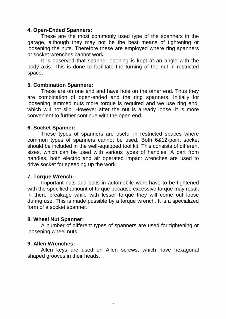
4. Open-Ended Spanners: These are the most commonly used type of the spanners in the
garage, although they may not be the best means of tightening or loosening the nuts. Therefore these are employed where ring spanners or socket wrenches cannot work.
It is observed that spanner opening is kept at an angle with the body axis. This is done to facilitate the turning of the nut in restricted space. 5. Combination Spanners:
These are on one end and have hole on the other end. Thus they are combination of open-ended and the ring spanners. Initially for loosening jammed nuts more torque is required and we use ring end, which will not slip. However after the nut is already loose, it is more convenient to further continue with the open end. 6. Socket Spanner:
These types of spanners are useful in restricted spaces where common types of spanners cannot be used. Both 6&12-point socket should be included in the well-equipped tool kit. This consists of different sizes, which can be used with various types of handles. A part from handles, both electric and air operated impact wrenches are used to drive socket for speeding up the work. 7. Torque Wrench:
Important nuts and bolts in automobile work have to be tightened with the specified amount of torque because excessive torque may result in there breakage while with lesser torque they will come out loose during use. This is made possible by a torque wrench. It is a specialized form of a socket spanner. 8. Wheel Nut Spanner:
A number of different types of spanners are used for tightening or loosening wheel nuts. 9. Allen Wrenches:
Allen keys are used on Allen screws, which have hexagonal shaped grooves in their heads.
8
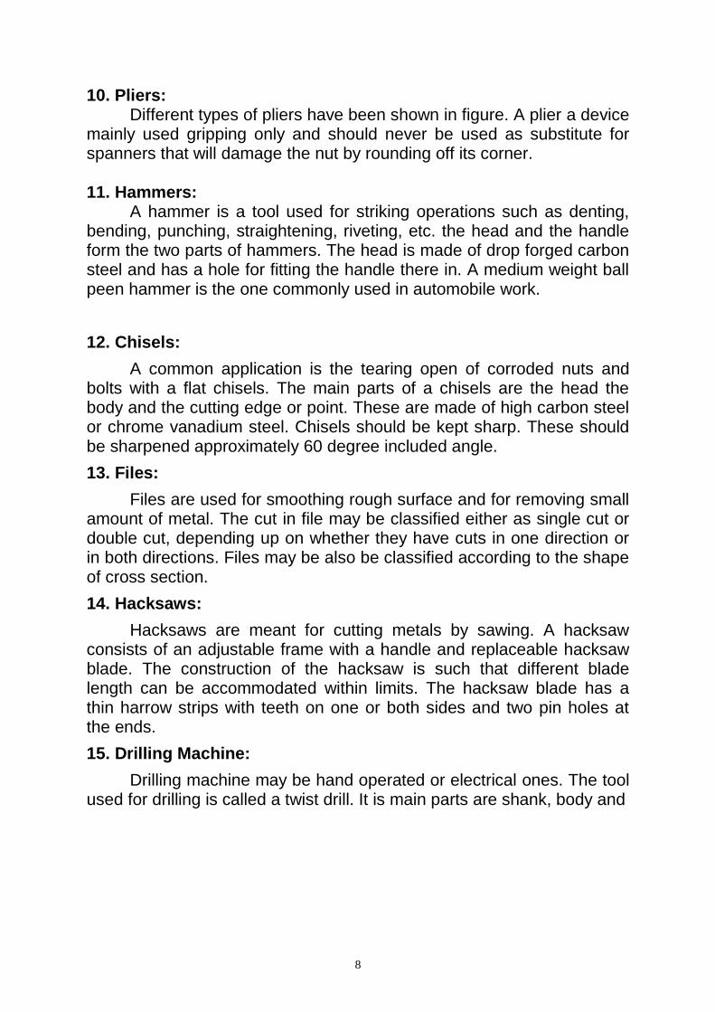
10. Pliers: Different types of pliers have been shown in figure. A plier a device
mainly used gripping only and should never be used as substitute for spanners that will damage the nut by rounding off its corner. 11. Hammers:
A hammer is a tool used for striking operations such as denting, bending, punching, straightening, riveting, etc. the head and the handle form the two parts of hammers. The head is made of drop forged carbon steel and has a hole for fitting the handle there in. A medium weight ball peen hammer is the one commonly used in automobile work.
12. Chisels:
A common application is the tearing open of corroded nuts and bolts with a flat chisels. The main parts of a chisels are the head the body and the cutting edge or point. These are made of high carbon steel or chrome vanadium steel. Chisels should be kept sharp. These should be sharpened approximately 60 degree included angle.
13. Files:
Files are used for smoothing rough surface and for removing small amount of metal. The cut in file may be classified either as single cut or double cut, depending up on whether they have cuts in one direction or in both directions. Files may be also be classified according to the shape of cross section.
14. Hacksaws:
Hacksaws are meant for cutting metals by sawing. A hacksaw consists of an adjustable frame with a handle and replaceable hacksaw blade. The construction of the hacksaw is such that different blade length can be accommodated within limits. The hacksaw blade has a thin harrow strips with teeth on one or both sides and two pin holes at the ends.
15. Drilling Machine:
Drilling machine may be hand operated or electrical ones. The tool used for drilling is called a twist drill. It is main parts are shank, body and
9
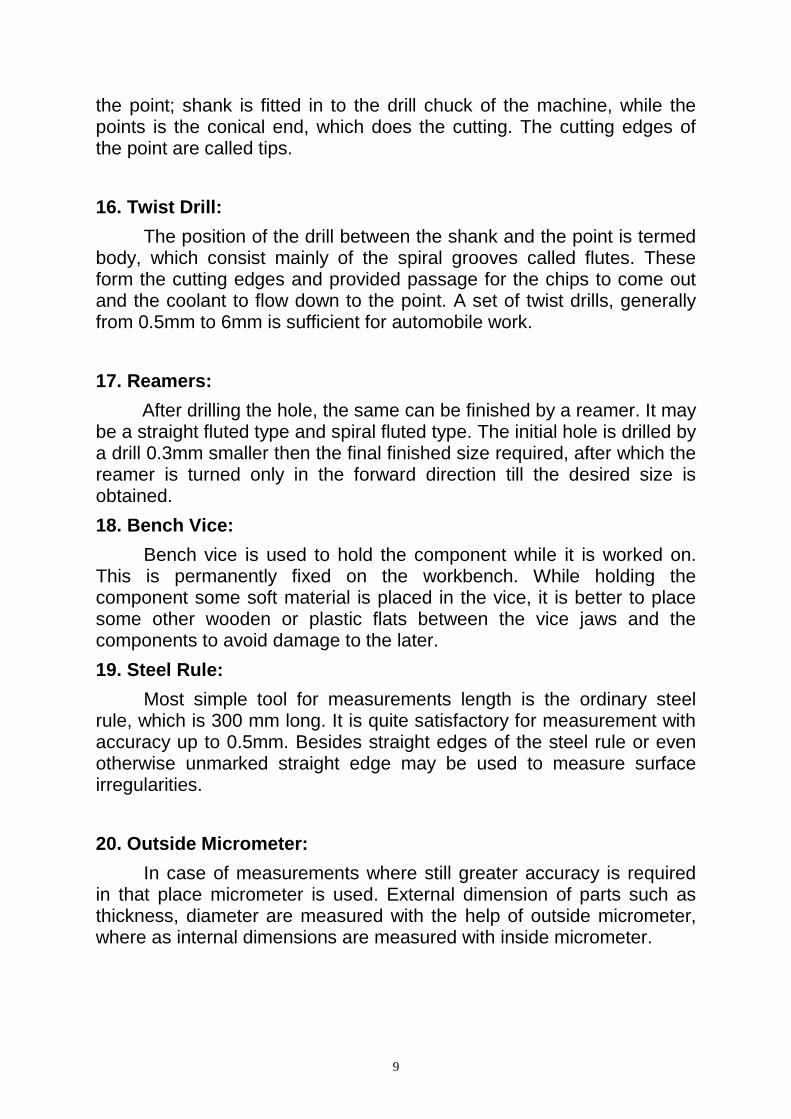
the point; shank is fitted in to the drill chuck of the machine, while the points is the conical end, which does the cutting. The cutting edges of the point are called tips.
16. Twist Drill:
The position of the drill between the shank and the point is termed body, which consist mainly of the spiral grooves called flutes. These form the cutting edges and provided passage for the chips to come out and the coolant to flow down to the point. A set of twist drills, generally from 0.5mm to 6mm is sufficient for automobile work.
17. Reamers:
After drilling the hole, the same can be finished by a reamer. It may be a straight fluted type and spiral fluted type. The initial hole is drilled by a drill 0.3mm smaller then the final finished size required, after which the reamer is turned only in the forward direction till the desired size is obtained.
18. Bench Vice:
Bench vice is used to hold the component while it is worked on. This is permanently fixed on the workbench. While holding the component some soft material is placed in the vice, it is better to place some other wooden or plastic flats between the vice jaws and the components to avoid damage to the later.
19. Steel Rule:
Most simple tool for measurements length is the ordinary steel rule, which is 300 mm long. It is quite satisfactory for measurement with accuracy up to 0.5mm. Besides straight edges of the steel rule or even otherwise unmarked straight edge may be used to measure surface irregularities.
20. Outside Micrometer:
In case of measurements where still greater accuracy is required in that place micrometer is used. External dimension of parts such as thickness, diameter are measured with the help of outside micrometer, where as internal dimensions are measured with inside micrometer.
10
21. Lifting Jacks:
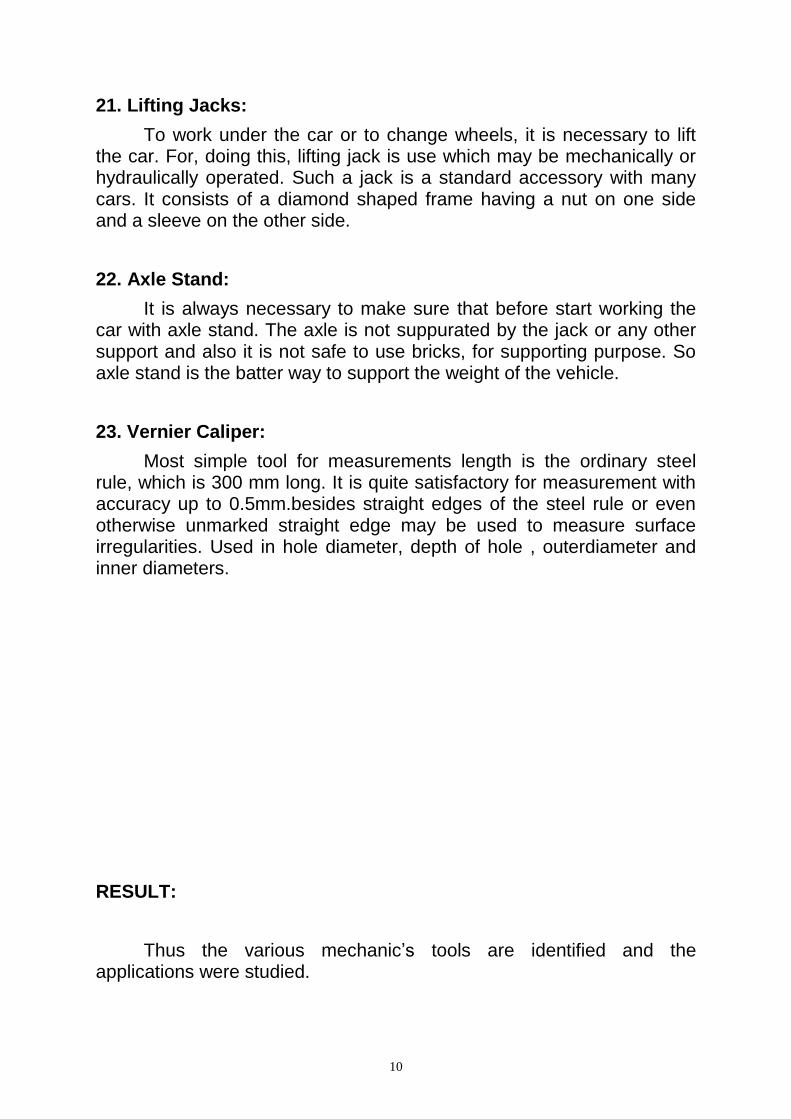
To work under the car or to change wheels, it is necessary to lift the car. For, doing this, lifting jack is use which may be mechanically or hydraulically operated. Such a jack is a standard accessory with many cars. It consists of a diamond shaped frame having a nut on one side and a sleeve on the other side.
22. Axle Stand:
It is always necessary to make sure that before start working the car with axle stand. The axle is not suppurated by the jack or any other support and also it is not safe to use bricks, for supporting purpose. So axle stand is the batter way to support the weight of the vehicle.
23. Vernier Caliper:
Most simple tool for measurements length is the ordinary steel rule, which is 300 mm long. It is quite satisfactory for measurement with accuracy up to 0.5mm.besides straight edges of the steel rule or even otherwise unmarked straight edge may be used to measure surface irregularities. Used in hole diameter, depth of hole , outerdiameter and inner diameters.
RESULT:
Thus the various mechanic’s tools are identified and the applications were studied.
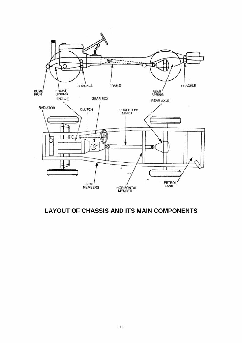
11
LAYOUT OF CHASSIS AND ITS MAIN COMPONENTS
12
Ex. No: Date:
STUDY OF AUTOMOBILE COMPONENTS AND ITS FUNCTIONS
AIM: To study the various auto components and function.
Layout of Chassis and its main Components:
The main components of the Chassis are given below
Frame: It is the base of the vehicle. Engine, clutch, gear box, rear axial etc
are mounted on the frame. Engine: The function of the heat engine is to convert the heat energy contained in the fuel into mechanical work.
Engines in which the combustion of fuel takes place inside the engines cylinder are known as internal combustion engines.
Ex: - Petrol, Diesel and Gas engines. Engines, in which the combustion of fuel takes place outside the engine cylinder, are known as external combustion engines.
Ex: - Steam engines.
Fuel Feed System: In Petrol Engine, the Petrol from the fuel tank reaches through the fuel pump, filter and carburettor to the engine cylinder. The fuel feed system consists of the following components:
1. Fuel Tank 2. Fuel Pump 3. Fuel Filter 4. Carburettor 5. In-take manifold 6. Fuel pipes or tubes 7. Gauge to indicate the fuel level in the fuel tank.
Function of Fuel feed System: 1. To store fuel in the tank. 2. To supply fuel to the engine in good condition i.e. the correct
quantity. 3. To indicate the fuel level in the tank.
13
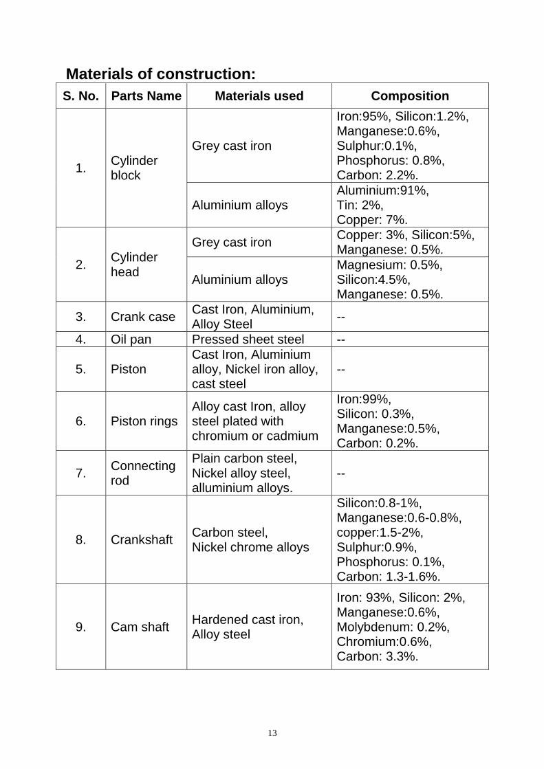
Materials of construction:
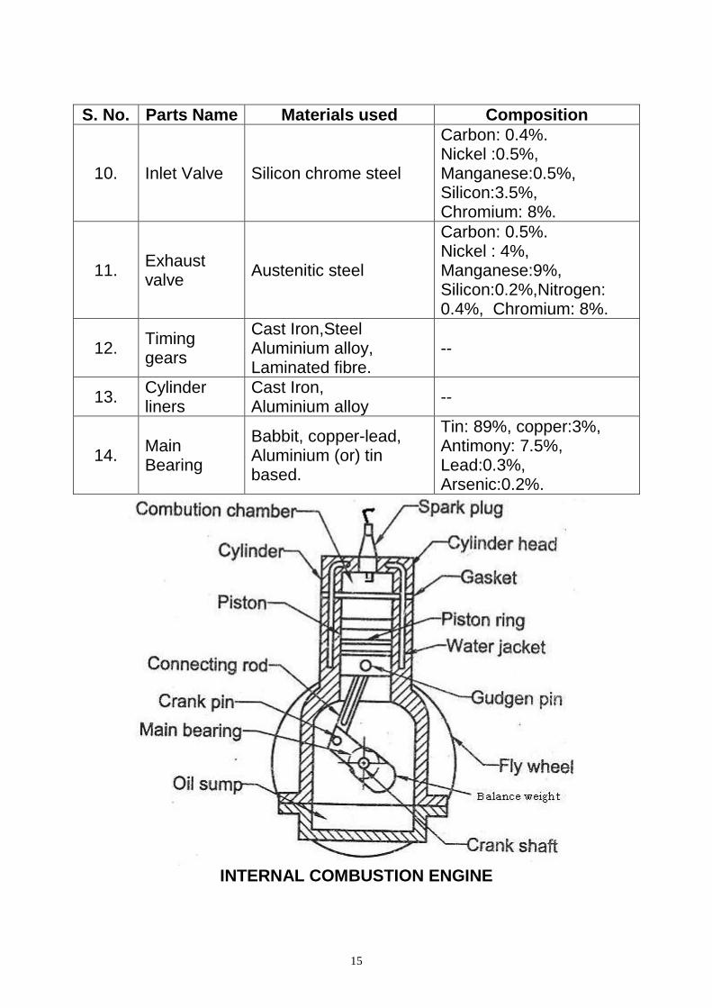
S. No. Parts Name Materials used Composition
1. Cylinder block
Grey cast iron
Iron:95%, Silicon:1.2%, Manganese:0.6%, Sulphur:0.1%, Phosphorus: 0.8%, Carbon: 2.2%.
Aluminium alloys Aluminium:91%, Tin: 2%, Copper: 7%.
2. Cylinder head
Grey cast iron Copper: 3%, Silicon:5%, Manganese: 0.5%.
Aluminium alloys Magnesium: 0.5%, Silicon:4.5%, Manganese: 0.5%.
3. Crank case Cast Iron, Aluminium, Alloy Steel
--
4. Oil pan Pressed sheet steel --
5. Piston Cast Iron, Aluminium alloy, Nickel iron alloy, cast steel
--
6. Piston rings Alloy cast Iron, alloy steel plated with chromium or cadmium
Iron:99%, Silicon: 0.3%, Manganese:0.5%, Carbon: 0.2%.
7. Connecting rod
Plain carbon steel, Nickel alloy steel, alluminium alloys.
--
8. Crankshaft Carbon steel, Nickel chrome alloys
Silicon:0.8-1%, Manganese:0.6-0.8%, copper:1.5-2%, Sulphur:0.9%, Phosphorus: 0.1%, Carbon: 1.3-1.6%.
9. Cam shaft Hardened cast iron, Alloy steel
Iron: 93%, Silicon: 2%, Manganese:0.6%, Molybdenum: 0.2%, Chromium:0.6%, Carbon: 3.3%.
14
Cooling System: During the combustion of air-fuel mixture enormous amount of heat is produced inside the engine cylinder. The temperature as high as 1500o to 2000o may be reached. It will break the lubricating film between the moving parts and may cause mechanical breakage C.F. the engine parts. Hence this temperature must be reduced to such a value, about 200oC to 250oC. Clutch:
Clutch is a device used in the transmission system of vehicle to engage and disengage the engine to the transmission. When the clutch is engaged the power flows from the engine to the rear wheels through the transmission system and the vehicle moves. When the clutch is disengaged, the power is not transmitted to the rear wheels and the vehicle is stops while the engine is running. The clutch is disengaged when starting the engine, when shifting gears, when the stopping the vehicle and when idling the engine. The clutch is engaged only when the vehicle is to move and it is kept engaged, when the vehicle is moving. The clutch also permits the gradual taking up of the load.
Types of Clutches: 1. Frictional Clutch a) Single Plate Clutch b) Multi Plate Clutch - wet type, dry type c) Cone clutch. 2. Centrifugal Clutch 3. Semi Centrifugal Clutch 4. Diaphragm Clutch 5. Hydraulic Clutch 6. Vacuum Clutch
7. Automatic Clutch (or) fluid flywheel or fluid coupling
Gear box:
The gear box is a device which is located between the clutch and the propeller shaft. It is used to transmit the power from clutch shaft to propeller shaft. When a vehicle is moving from rest it required more torque and less speed.
15
S. No. Parts Name Materials used Composition
10. Inlet Valve Silicon chrome steel
Carbon: 0.4%. Nickel :0.5%, Manganese:0.5%, Silicon:3.5%, Chromium: 8%.
11. Exhaust valve
Austenitic steel
Carbon: 0.5%. Nickel : 4%, Manganese:9%, Silicon:0.2%,Nitrogen: 0.4%, Chromium: 8%.
12. Timing gears
Cast Iron,Steel Aluminium alloy, Laminated fibre.
--
13. Cylinder liners
Cast Iron, Aluminium alloy
--
14. Main Bearing
Babbit, copper-lead, Aluminium (or) tin based.
Tin: 89%, copper:3%, Antimony: 7.5%, Lead:0.3%, Arsenic:0.2%.
INTERNAL COMBUSTION ENGINE
16
Similarly more torque is required at the time of hill climbing and accelerating the purpose of gear box is:
1. To provide high torque at the time of starting, accelerating, hill climbing and pulling the load.
2. To give more speed at the time of normal running. (Less torque)
3. To provide a natural position, so that engine transmits the power to clutch shaft, but propeller shaft remain idle.
4. To reverse the vehicle. The above are obtained by a set gears enclosed in a gear box and gear changing Mechanism. Types of gear boxes: 1. Sliding mesh gear box 2. Constant mesh gear box 3. Synchro-mesh gear box 4. Epicyelic gear box
Universal Joint: A universal joint is used where two shafts are connected at angle to transmit torque. The output of the gar box or main shaft, propeller shaft and final drive are not in one line and hence the connection between them is made by the universal joint. One universal joint is used to connect the main shaft and propeller shaft at required angle, other universal joint is used to connect the other end of the propeller and final drive with some angle. Thus the connection between the three shafts are flexible and at an angle with one another. Types of universal joint: 1) Non constant (or) variable velocity joint: a) Cross type (or) spider and yoke type (or) Hook's joint b) Pot type c) Flexible ring type d) Ball and turning type. 2) Constant velocity type: a) Tracta type b) Bendix type c) Rzeppa type
17
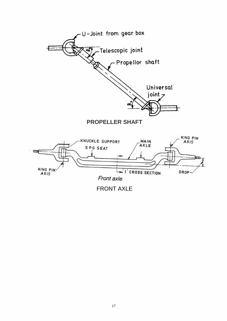
PROPELLER SHAFT
FRONT AXLE
18
Propeller Shaft: The propeller shaft transmits power from the gearbox to the rear
axle, accommodates change in length, and transmits motion at varying angles. It is connected between the gear box side universal joint and differential unit side universal joint.
Material of propeller shaft: The propeller shaft has to withstand the torsion stresses of the transmitting torque. But it should be light and well balanced so that vibrations will not occur at high speeds. So it should be made of a strong steel tube. Solid propeller shaft is also used. The propeller shaft may be in two section supported by a center bearings and coupled together by universal joint. This is for lengthy vehicle.
Differential:
The function of the differential is to allow each rear wheel to rotate at different speeds during turning but at the sometime transmit equal torque to each wheel when both wheels have equal traction. Front axle:
The front axle is used to carry the weight of the front part of the vehicle as well as to facilitate steering and absorb shocks due to road surface variation. It must be rigid and robust in construction. It is usually steel drop forging having 0.4% carbon steel or 1 to 3% Nickel steel. Functions:
1. It carries the hubs and the wheels. 2. It carries the weight of the front part of the vehicle. 3. It works as cushion through the spring which facilitates a
comfortable ride. 4. It controls the ride through shocks absorber fitted on H. It
carries the brake system. 5. It carries stub axle, king pin, Steering arm by which the vehicle
steers.
19
6. In case of four wheel drive it also transmits power to road
wheels. 7. It includes steering mechanism, braking mechanism and
suspension etc.. Rear axle:
The power from differential is transmitted to rear wheel by rear axle. Depending upon the methods of supporting the rear axle and mounting the rear wheels, the rear axles are classified into three types are:
1) Semi floating type 2) Three-quarter floating type 3) Full floating type
Functions of Rear Axle: As the rear axle is suspended from the body of the vehicle by
leaf springs attached to the axle housing. The rear axle performs several functions which are as under;-
1. Changing the direction of driveshaft rotation by 90 degrees to rotate the axle shafts.
2. Providing a final speed reduction between the drive shaft and the axle shafts through the final – drive gears or differential gears.
3. Providing differential action , so that one wheel can turn at a different speed as compared to the both wheel, when required,
4. Providing axle shafts or half shafts to drive the rear wheels. 5. Acting as a thrust and torque reaction member during
acceleration and breaking.
RESULT:
Thus the various auto components and function were studied.

20
FOUR STROKE PETROL ENGINE

21
EX.NO: DATE:
DISMANTLING AND ASSEMBLING OF FOUR STROKE PETROL ENGINE AND IDENTIFICATION OF PARTS
AIM:
To dismantle and assemble the given four stoke petrol engine and to identify the parts.
TOOLS REQUIRED:
1. Double end spanner set. 2. Ring end spanner set. 3. Box spanner set. 4. Hammer
5. Cutting plier. 6. Torque wrench 7. Feeler gauge 8. Screw driver 9. Emery paper
PROCEDURE:
1. Remove the connection from the battery 2. Remove the drain cock from the radiator and drain the water. 3. Remove the drain plug from the oil sump and drain the oil. 4. Remove the air cleaner, valve, carburettor, rock arm assembly, push rod, and
rocker arm lubrication tube. 5. Then loose the engine head bolts and remove the gaskets carefully. Then
remove the engine head and place it on a workbench. 6. Punch the valves and with the help of lock washer valve spring compressor
remove the valve spring, valve lock cup and remove the valves from the head. 7. Clean the valves, rocker arm, pushrod, tappet, valve guide, valve spring,
valve lock cup etc. if any parts are damaged replace it with new one. 8. After removing the carburettor from the engine body, dismantle all the parts
from the carburettor and clean it using petrol and compressed air. 9. Remove the inlet manifold and exhaust manifold from the engine block and
remove the gaskets carefully. 10. Clean the inlet manifold using petrol and remove the carbon from the exhaust
manifold with the help of wire brush and finally clean the manifold by kerosene.
11. Then assemble all the parts by reverse of dismantling procedure. And check timing and adjust the distributor for correct advance.
12. Then start the engine and correct the low speed screw, needle screw and fit the air filter.
RESULT:
Thus the given four-stroke petrol engine was dismantled, parts are identified and assembled.

22
FOUR STROKE DIESEL ENGINE

23
EX.NO: DATE:
DISMANTLING AND ASSEMBLING OF FOUR STROKE DIESEL ENGINE AND IDENTIFICATION OF PARTS
AIM:
To dismantle and assemble the given four stoke diesel engine and to identify the parts.
TOOLS REQUIRED:
1. Double end spanner set. 2. Ring end spanner set. 3. Box spanner set. 4. Hammer
5. Cutting plier. 6. Torque wrench 7. Feeler gauge 8. Screw driver 9. Emery paper
PROCEDURE:
1. Remove the connection from the battery 2. Remove the drain cock from the radiator and drain the water. 3. Remove the drain plug from the oil sump and drain the oil. 4. Remove the air cleaner, valve, fuel pump, injection pump, rocker arm
assembly, and Push rod. 5. Then loose the engine head bolts and remove the gaskets carefully.
Then remove the engine head and place it on a workbench. 6. Punch the valves and with the help of lock washer valve spring
compressor and remove the valve spring, valve lock cup and remove the valves from the head.
7. Then clean the valves, rocker arm, push rod, tappet, value guide, value spring, value lock cup etc. if any parts are damaged replace with new one.
8. Remove the injector from the engine body and dismantle all the parts from the injector and injection pump.
9. Clean the components using compressed air. 10. Remove the inlet manifold and exhaust manifold from the engine block,
and remove the gaskets carefully. 11. Clean the inlet manifold using petrol and remove the carbon from the
exhaust manifold with the help of wire brush and finally clean the manifold by kerosene.
12. Then assemble all the parts by reverse of dismantling procedure. And check timing and adjust the distributor for correct advance.
13. Then start the engine and correct the low speed screw, Needle screw and fit the air filter.
RESULT:
Thus the given four-stroke diesel engine was dismantled, parts are identified and assembled.
24
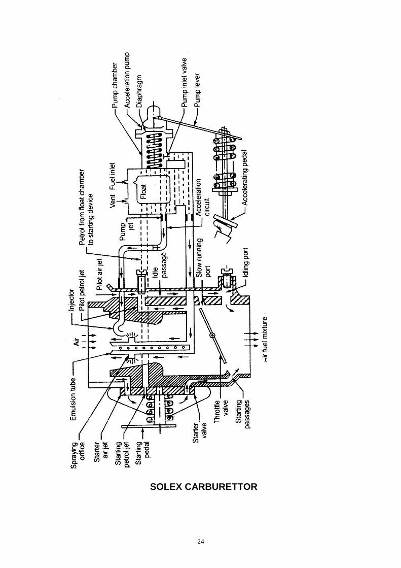
SOLEX CARBURETTOR
25
EX. NO: DATE: DISMANTLING, INSPECTING, OVERHAULING AND
ASSEMBLING OF SOLEX CARBURETTOR
AIM: To learn how to dismantle, clean, inspect, overhaul, and assemble the given Solex carburettor TOOLS AND EQUIPMENTS:
1. Double end spanner set. 2. Ring spanner set. 3. Box spanner set. 4. Hammer. 5. Screw driver. 6. Emery sheet. 7. Solex carburettor 8. carburettor tool kit
PROCEDURE:
1. Disconnect the fuel lines and remove the air cleaner.
2. Remove the carburettor and cover the manifold holes with proper
covering.
3. Remove the accelerator jet.
4. Remove the float chamber cover and then remove the pilot jet.
5. Clean the needle valve, acceleration pump and the non return valve by
petrol and test for,
Fuel leakage
Broken gasket
Proper vent in float chamber
Leakage in needle valve
Broken pump leather washer
6. Make sure the condition of the gasket while replacing.
7. Mount the carburettor in its place and re-connect the fuel lines and the
air cleaner
8. Start the vehicle and check its performance.
RESULT: Thus the Solex carburettor is dismantled, inspected, overhauled and assembled.
26
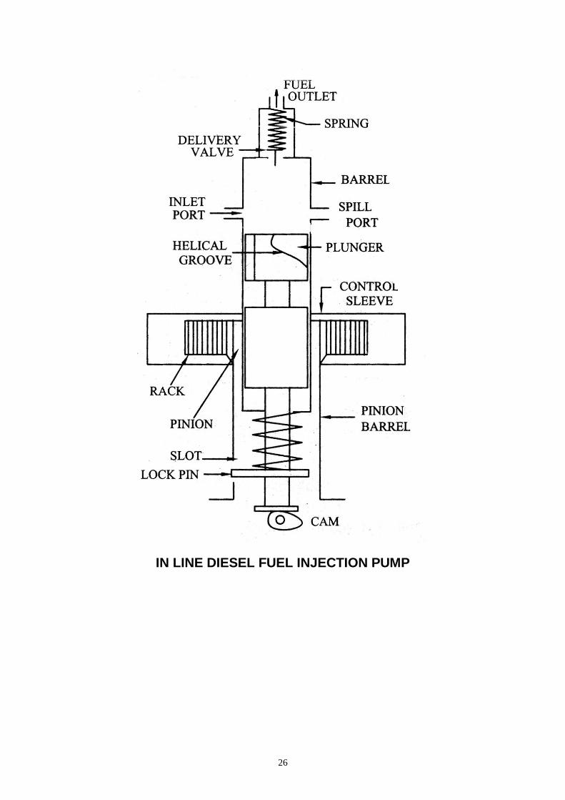
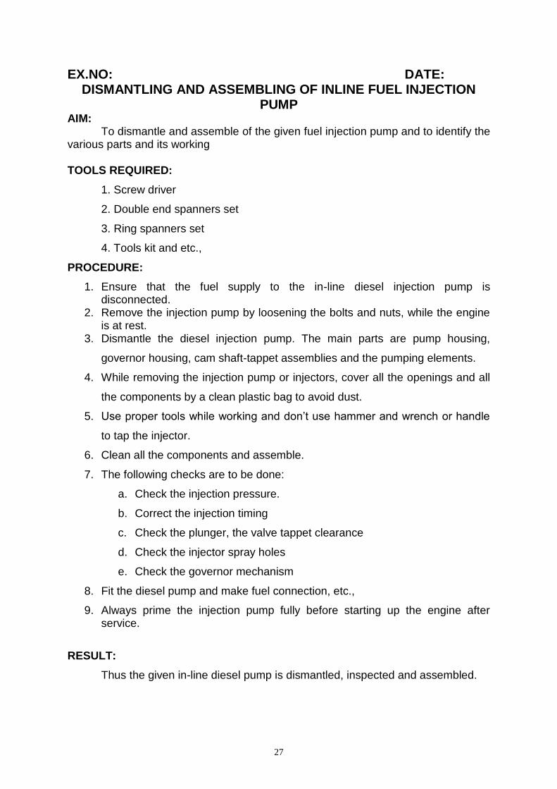
IN LINE DIESEL FUEL INJECTION PUMP
27
EX.NO: DATE: DISMANTLING AND ASSEMBLING OF INLINE FUEL INJECTION
PUMP
AIM: To dismantle and assemble of the given fuel injection pump and to identify the various parts and its working TOOLS REQUIRED:
1. Screw driver
2. Double end spanners set
3. Ring spanners set
4. Tools kit and etc.,
PROCEDURE:
1. Ensure that the fuel supply to the in-line diesel injection pump is disconnected.
2. Remove the injection pump by loosening the bolts and nuts, while the engine is at rest.
3. Dismantle the diesel injection pump. The main parts are pump housing,
governor housing, cam shaft-tappet assemblies and the pumping elements.
4. While removing the injection pump or injectors, cover all the openings and all
the components by a clean plastic bag to avoid dust.
5. Use proper tools while working and don’t use hammer and wrench or handle
to tap the injector.
6. Clean all the components and assemble.
7. The following checks are to be done:
a. Check the injection pressure.
b. Correct the injection timing
c. Check the plunger, the valve tappet clearance
d. Check the injector spray holes
e. Check the governor mechanism
8. Fit the diesel pump and make fuel connection, etc.,
9. Always prime the injection pump fully before starting up the engine after service.
RESULT:
Thus the given in-line diesel pump is dismantled, inspected and assembled.

28
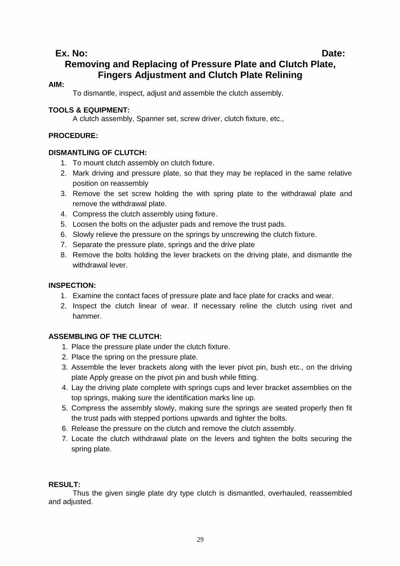
CLUTCH PLATE
SINGLE PLATE CLUTCH
29
Ex. No: Date: Removing and Replacing of Pressure Plate and Clutch Plate,
Fingers Adjustment and Clutch Plate Relining AIM: To dismantle, inspect, adjust and assemble the clutch assembly. TOOLS & EQUIPMENT: A clutch assembly, Spanner set, screw driver, clutch fixture, etc., PROCEDURE: DISMANTLING OF CLUTCH:
1. To mount clutch assembly on clutch fixture.
2. Mark driving and pressure plate, so that they may be replaced in the same relative
position on reassembly
3. Remove the set screw holding the with spring plate to the withdrawal plate and
remove the withdrawal plate.
4. Compress the clutch assembly using fixture.
5. Loosen the bolts on the adjuster pads and remove the trust pads.
6. Slowly relieve the pressure on the springs by unscrewing the clutch fixture.
7. Separate the pressure plate, springs and the drive plate
8. Remove the bolts holding the lever brackets on the driving plate, and dismantle the
withdrawal lever.
INSPECTION:
1. Examine the contact faces of pressure plate and face plate for cracks and wear.
2. Inspect the clutch linear of wear. If necessary reline the clutch using rivet and
hammer.
ASSEMBLING OF THE CLUTCH:
1. Place the pressure plate under the clutch fixture.
2. Place the spring on the pressure plate.
3. Assemble the lever brackets along with the lever pivot pin, bush etc., on the driving
plate Apply grease on the pivot pin and bush while fitting.
4. Lay the driving plate complete with springs cups and lever bracket assemblies on the
top springs, making sure the identification marks line up.
5. Compress the assembly slowly, making sure the springs are seated properly then fit
the trust pads with stepped portions upwards and tighter the bolts.
6. Release the pressure on the clutch and remove the clutch assembly.
7. Locate the clutch withdrawal plate on the levers and tighten the bolts securing the
spring plate.
RESULT: Thus the given single plate dry type clutch is dismantled, overhauled, reassembled and adjusted.

30
4-SPEED CONSTANT MESH GEAR BOX
A - Clutch shaft gear wheel
H,G,F & K - Main shaft gear wheel
B, C, D, E & I – Lay shaft gear wheel
J - Idler gear wheel
1,2 - Sliding Dog clutch
FIND OUT THE GEAR RATIO
To find out gear ratio using formula:
Gear ratio =gear drivingin teeth No.of
gear driven in teeth No.of
31
Ex.No: Date: DISMANTLING, INSPECTING AND ASSEMBLING OF CONSTANT
MESH GEAR BOX AND FINDING OUT THE GEAR RATIO AIM:
To dismantle, inspect and assemble the given Constant mesh gear box and
finding out the gear ratio
TOOLS & EQUIPMENT:
Constant mesh gear box, set of spanners, bearing puller, mallet, pliers, screw drivers
etc.,
PROCEDURE:
1. Disconnect battery terminals.
2. Remove front and rear propeller shaft bolts and removed propeller shaft to the
chassis frame.
3. Disconnect clutch assembly.
4. Disconnect speed o meter cable reverse indicator switch wiring connections.
5. Drain gear box trolley oil in a clean container.
6. Locate the gear box trolley under the gear box and unscrew clutch housing unit.
7. Check for natural position of selectors spindles, after remove selector casing unit.
8. Remove rear flange from main shaft.
9. Remove clutch shaft, ball bearing, main shaft, counter shaft, pinion wheel, dog
clutch and roller bearings from casing.
10. Clean all parts in kerosene.
11. To assemble counter shaft assembly.
12. To assemble main shaft, assembly.
13. Fit the 1st
gear, sliding dog clutch, reverse gear, pinion wheel, and thrust washer.
14. Fit 2nd
gear and 3rd
gear fixed dog clutch, and sliding dog clutch.
15. Fit 4th and 5
th fixed dog clutch and sliding dog clutch.
16. To check the individual gears end play measure the height difference between the
bush and the gear.
17. Check for free engagement of sliding dog clutches.
18. Check for free rotation of I, Reverse, II, III and IV gear wheel.
19. Fit the clutch shaft and ball bearing.
20. Fit the flange, and selector mechanism to clutch assembly, gear box casing.
21. Fill lubricating oil. Check for filly of lubricating oil up to required level.
22. Check for any oil leakage, noise and smooth running.
23. Fit the vehicle, Connect to Battery terminals.
24. Check for proper gear engagement for different in running condition.
RESULT:
Thus the constant mesh gear box is dismantled, inspected and reassembled.
32
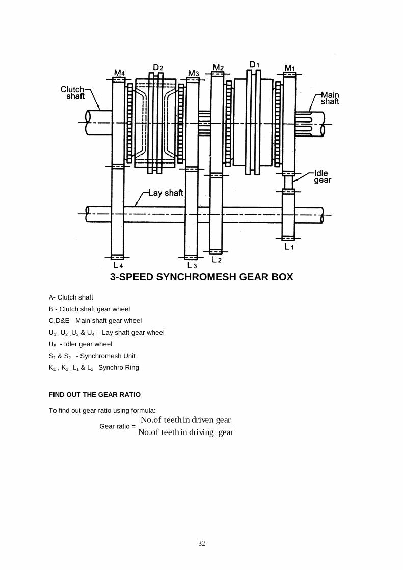
3-SPEED SYNCHROMESH GEAR BOX
A- Clutch shaft
B - Clutch shaft gear wheel
C,D&E - Main shaft gear wheel
U1 , U2 ,U3 & U4 – Lay shaft gear wheel
U5 - Idler gear wheel
S1 & S2 - Synchromesh Unit
K1 , K2 , L1 & L2 Synchro Ring
FIND OUT THE GEAR RATIO
To find out gear ratio using formula:
Gear ratio =gear drivingin teeth No.of
gear driven in teeth No.of

33
Ex.No: Date: DISMANTLING, INSPECTING AND ASSEMBLING OF
SYNCHROMESH GEAR BOX AND FINDING OUT THE GEAR RATIOS AIM: To dismantle, inspect and assemble the given Synchromesh gear box and finding out the gear ratios
TOOLS & EQUIPMENT: Synchromesh gear box, set of spanners, bearing puller, mallet, pliers, screw drivers etc.,
PROCEDURE:
1. Disconnect battery terminals. 2. Remove front and rear propeller shaft bolts and removed propeller shaft to the
chassis frame. 3. Disconnect clutch assembly. 4. Disconnect speed o meter cable reverse indicator switch wiring connections. 5. Drain gear box trolley oil in a clean container. 6. Locate the gear box trolley under the gear box and unscrew clutch housing unit. 7. Check for natural position of selectors spindles, after remove selector casing
unit. 8. Remove rear flange from main shaft. 9. Remove clutch shaft, ball bearing, main shaft, counter shaft, pinion wheel,
synchro ring, synchro body, synchro pack and roller bearings from casing. 10. Clean all parts in kerosene. 11. To assemble counter shaft assembly. 12. To assemble main shaft, assembly. 13. Fit the 1st gear, synchro mesh unit, reverse gear, pinion wheel, and thrust
washer. 14. Fit 2nd gear and 3rd gear fixed synchro mesh unit, and sliding dog clutch. 15. Fit 4th and 5th fixed dog clutch and synchro mesh unit. 16. To check the individual gears end play measure the height difference between
the bush and the gear. 17. Check for free engagement of synchro mesh units. 18. Check for free rotation of I, Reverse, II, III and IV gear wheel. 19. Fit the clutch shaft and ball bearing. 20. Fit the flange, and selector mechanism to clutch assembly, gear box casing. 21. Fill lubricating oil. Check for filly of lubricating oil up to required level. 22. Check for any oil leakage, noise and smooth running. 23. Fit the vehicle. 24. Connect to battery terminals. 25. Check for proper gear engagement for different in running condition.
RESULT: Thus the synchromesh gear box is dismantled, inspected and reassembled.
34
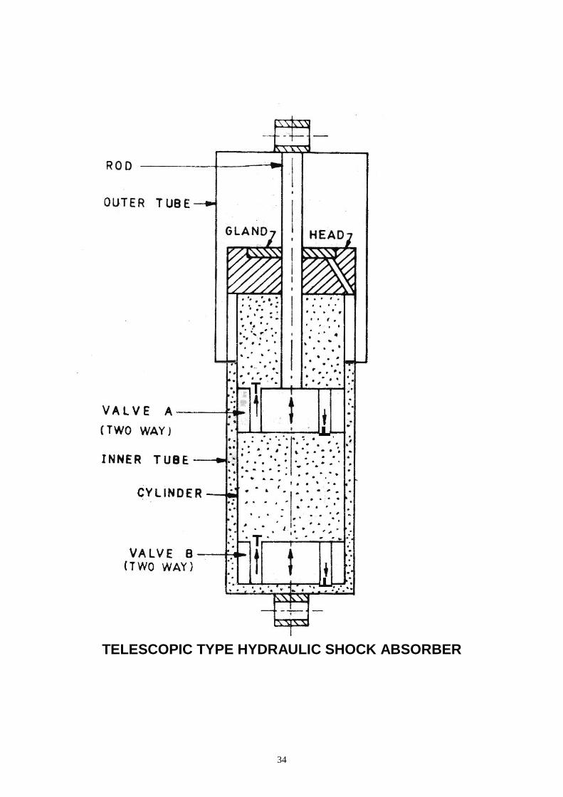
TELESCOPIC TYPE HYDRAULIC SHOCK ABSORBER
35
Ex.No: Date: REMOVING AND REFITTING OF SHOCK ABSORBER
AIM:
To remove and refit of shock absorber in given vehicle
TOOLS AND EQUIPMENTS:
Spanner sets, Screw jack, Vehicle.
PROCEDURE:
1. Screw jack is placed under the vehicle.
2. Jack up the vehicle.
3. Loosen the top and bottom bolts of shock absorber.
4. Remove the shock absorber from the suspension.
5. Clean the rubber bush and outer surface.
6. The bottom eye is fixed, and the top eye is pulled and pushed
several times.
7. Tightness must be felt
8. When there is true motion that the shock absorber is unfit for
further use. So, a new shock absorber of same capacity must be
refitted.
RESULT:
Thus the shock absorber is removed, checked and refitted.
36
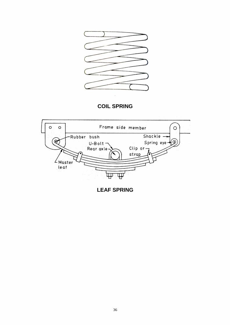
COIL SPRING
LEAF SPRING
37
Ex. No: Date: DISMANTLING AND ASSEMBLING OF LEAF AND COIL SPRING
AIM: To dismantle, inspect and assemble of leaf and coil spring
TOOLS AND EQUIPMENT: Spanner sets, Screw jack, horse, vehicle. PROCEDURE:
DISMANTLING AND ASSEMBLING OF LEAF SPRING:
1. Jack up the vehicle using screw jack. Horse stand is placed under the
axle for support.
2. The leaf spring assembly is removed from the chassis by loosing the
bolts at two ends and U bolt.. Remove the shackle, bush, pin.
3. All clips are removed. The spring plates are inspected separately for
any breakage.
4. Due to continuous use, the spring assembly gets sagged or gets
straightened.
5. Under these circumstances, the spring plate is hammered through out is
length by placing on a special fixture which will give designed cure. This
operation is called re-cambering of spring.
6. Proper lubricant is applied and then all springs are assembled.
7. When the shape of spring is different from one another, the opposite
spring must also be re-cambered.
DISMANTLING AND ASSEMBLING OF COIL SPRING:
1. Jack up the vehicle. The wheels are removed.
2. The shock absorber is removed.
3. Now, the upper and lower wish bone arms are free and so, the coil
spring can be removed easily.
4. The coil spring is tested on compressive load, if change in length is
found; it’s deviated from the manufactures specification. Spring is
replaced with new one.
5. Rubber pad is checked for any damage. Then refit the coil spring in
vehicle.
RESULT:
Thus the Leaf and Coil spring is dismantled, inspected and assembled.
38
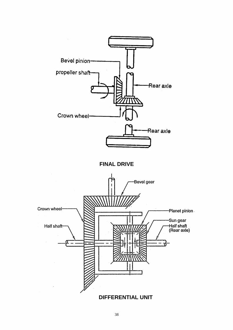
FINAL DRIVE
DIFFERENTIAL UNIT
39
Ex. No: Date: FINAL DRIVE AND DIFFERENTIAL UNITS
AIM: To Dismantle and assemble, inspect of final drive and differential units.
TOOLS AND EQUIPMENTS: Given is a differential unit and tools kit. PROCEDURE: 1. Drain the oil in the differential by removing the drain plug and remove the
half axle shaft. 2. Disconnect the propeller shaft. 3. Remove the differential bearing. 4. Remove the ring gear, pinion shaft and the gears. 5. Check the differential case for wear and the ring gear for run out. 6. Remove the front and rear bearing cups from the carrier and check the
bores. 7. Check and adjust the pinion depth & check and correct the pinion pre-load. 8. Install the differential case in the carrier. 9. Fill up the recommended oil in the housing. 10. Before connecting the unit with the axle shaft and propeller shaft, Check the following. a. Is sufficient lubricant of correct grade is in the casing. - b. Differential case bearing and pinion shaft bearing for wear: c. Sufficient backlash. d. Pinion gear and play.
a. Back lash adjustment of differential gears: The assembly of differential spider bevel gears & axle shaft gears should rotate freely without binding and the black lash between them should be in specification. To adjust the back lash select correct thrust washer thickness.
b. Tail pinion preload: Taper roller bearings of the tail pinion assembly have to be assembled with a preload to give a friction moment. The spacer rings are available in different thickness. Found the friction moment of bearings, compare with the specification and select correct spacer thickness.
c. Back lash adjustment: Using dial gauge find the back lash between crown wheel and tail pinion. If back lash less than the specification loosen the left adjusting ring and equally tighten the right one. If back lash greater than the specification loosen the right adjusting ring and equally tighten the left one. RESULT: Thus the given differential unit is dismantled, overhauled, reassembled and adjusted for backlash, correct teeth contact of crown and pinion.
40
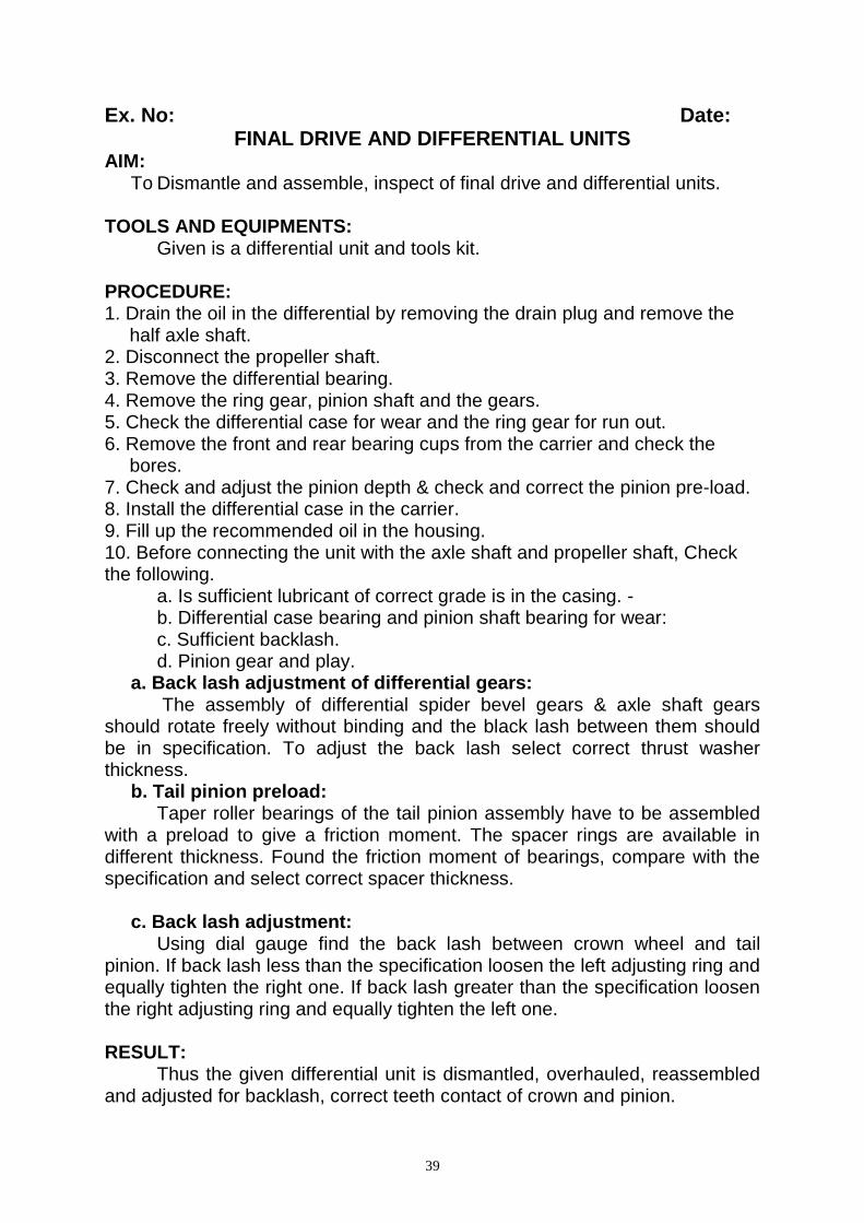
LAYOUT OF HYDRAULIC BRAKES
BLEEDING OF HYDRAULIC BRAKES

41
Ex. No: Date: OVERHAULING, ADJUSTING AND BLEEDING HYDRAULIC
BRAKING SYSTEM AIM: To dismantle, overhaul, adjust and bleed the hydraulic brake system. TOOLS AND EQUIPMENTS: Given is an auto vehicle with hydraulic brake system, tools kit, rubber tube, and bottle. PROCEDURE:
1. First to check the height of the brake pedal. It is normally lower than the clutch
pedal.
2. Start the engine, Depress the brake pedal and measure the clearance
between brake pedal and floor. It should be within the specification, if less
indicates the wear in rear brake shoe or air in the line.
3. If front brake is disc brake. Inspect the brake lining pad thickness, inner parts
of caliper brake, Brake disc thickness.
4. Inspect the master cylinder parts for wear or damage, replace if necessary.
Inspect master cylinder bore for coring or corrosion.
5. Inspect wheel cylinder parts for wear, cracks, corrosion or damage.
6. If rear is drum brake, Inspect the brake drum for cleanliness, check wear of its
braking surface, brake shoe lining thickness and spring damage or defective.
7. Normally rear brake has self- adjusting mechanism otherwise adjustment
mechanism is providing in the back plate for adjust the clearance between
brake shoe and drum.
BLEEDING OF HYDRAULIC BRAKING SYSTEM :
1. Check the master cylinder for the fluid level in the reservoir.
2. Check and clean the bleed valve.
3. Select one of the wheel cylinders which is far away from the master cylinder,
4. Connect one end of the rubber tube to the drain nipple and the other end to
the jar containing brake oil.
5. Press the brake pedal several times and open bleed valve to note whether air
bubbles are escaping while keeping the pedal pressed.
6. Close the valve and release the pedal.
7. Repeat the procedure until all the air present in the system is released.
8. Remove the tube and repeat the same for the other three wheel cylinders.
9. After the process is over, check the fluid level again and refill.
RESULT:
Thus the overhauling, bleeding and adjusting of the hydraulic brake are done.
42
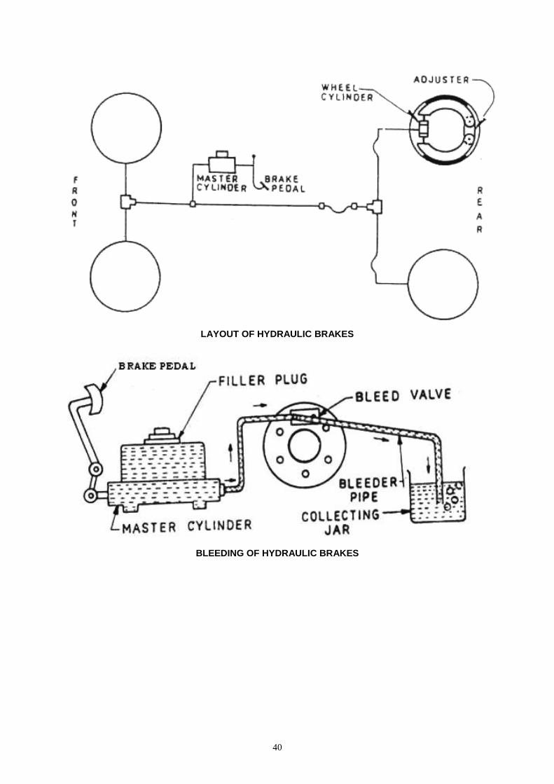
CASTER ANGLE CAMBER ANGLE
TOE
43
Ex. No: Date: WHEEL ALIGNMENT
AIM: To learn to check and correct the front wheel alignment TOOLS AND EQUIPMENT: Vehicle, tools kit and Wheel Alignment machine
PROCEDURE: The wheel alignment refers to the position of the wheel and steering mechanism that gives the vehicle the directional stability. It promotes eases of steering and reduces tyre ware to a minimum. It is very important to consider the following factors.
1. Factors pertaining to wheels (a) Balance of wheels (b) Brake adjustment (c) Inflation of tyre
2. Steering linkage 3. Steering geometry
(a) Primary (or) Adjustment angles (1) Camber angle (2) Caster angle
(3) Toe in and Toe out (b) Secondary (or) Diagnostic angles (1) Steering Axis Inclination (S.A.I) (2) Turning angle (or) Toe out on turns (3) Thrust angle (4) Included angle (5) Set back & Scrub radius 4. Suspension system
For proper wheel alignment it is necessary that camber angle, caster angle, toe in and toe out must be set properly. They should be with the specified limits according to the vehicle manufacturer.
1. Castor: The angle between the vertical line and the king pin centre line in plane of the wheel, when viewed from the side is called castor angle. The castor angle ranges from 2° to 8°. This helps the front wheel to maintain a straight a head position and to offset road crown. Incorrect castor may result pill to one side, instability and hard steering.
2. Camber: The angle between the centre line and the vertical line of the type, when viewed from the front of the vehicle is known as camber. Camber should not exceed 2°. The camber on modern vehicle is adjusted by means of shims or an eccentric cam in the control arm shaft.
3. Toe: This is the difference between the rear and front ends of the front wheel. Toe is measured in 3 to 5 mm.
RESULT: Thus the front wheel alignment is checked and corrected in the vehicle.
44
Disc Wheel Dynamic Balance Symbol
WHEEL SPECIFICATION:
Diameter of wheel : Width of wheel :
Added weight
Left side Right side

45
EXNO: DATE:
STATIC AND DYNAMIC BALANCING OF WHEEL AIM:
To balance the unbalanced wheel due to unbalanced force
distribution
TOOLS:
Balancing weights, Pin hammer, Cone, Measuring scale etc
MACHINE:
Wheel balancing machine
PROCEDURE:
(i) Dynamic balance:
1. Fix the wheel assembly in the mechanic spindle with correct cone
select the wheel assembly in the balancing mechanic.
2. Check the three following dimension’s.
a) Distance between the machine and to the wheel end.
b) Width of the rim.
c) Rim diameter in inches.
3. after checking the measurement feed it in the machine in a, b, c
Column’s respectively.
4. Switch on the machine make sure that the assembly is fitted tight
enough.
5. After attaining 100 rpm. The machine will come to rest showing, how
much weight should be added to the left and right side of wheel in
order to make it a balanced one side.
6. Rotate the wheel assembly, when the all height in the left or right
glow fix
7. It in the 12Hrs position and added the weight are specified.
8. Again switch on the machine for zero verification. Thus the wheel is
balanced
46
Static Balance Symbol
WHEEL SPECIFICATION: Diameter of wheel : Width of wheel :
Added weight
Left side Right side
47
(ii) Static Balance:
1. Fix the wheel assembly in the mechanic spindle with correct cone
select to the wheel assembly in the balancing mechanic.
2. Check the three following dimension’s.
a) Distance between the machine and to the first edge of the wheel
(al )
b) Distance between the machine and to the second edge of the
wheel ( aE )
c) Width of the rim.
d) Rim outside diameter in inches.( dl,)
e) Rim inside diameter in inches.( dE)
3. After checking the measurement feed it in the machine in a, b, c, d,
and e Column’s respectively.
4. Switch on the machine make sure that the assembly is fitted tight
enough.
5. After attaining 100 rpm. The machine will come to rest showing, how
much weight should be added to the left and right side of wheel in
order to make it a balanced one side.
6. Rotate the wheel assembly, when the all height in the left or right
glow fix
7. It in the 12Hrs position and added the weight are specified.
8. Again switch on the machine for zero verification. Thus the wheel is
balanced
RESULT: - Thus the given unbalanced wheel has been balanced and verified.
48
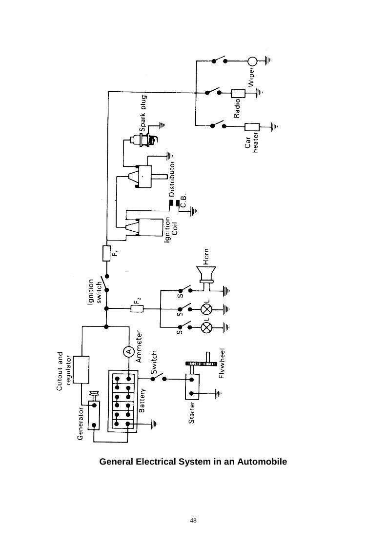
General Electrical System in an Automobile

49
Ex. NO: DATE:
STUDY OF GENERAL ELECTRICAL SYSTEM IN AN AUTOMOBILE
AIM:
To study the automobile electrical system.
INTRODUCTION:
Every automobile of today contains an electric power plant under its hood, which produces and stores electric energy that is delivered either at low voltage or in the form of high voltage. Electrical equipment fitted on automobiles is required to operate without failure for very long periods with little attention. Further, it is made to operate under widely varying climatic conditions. At times, the power delivered by the system may be about 40 to 50 times in excess of the normal output for short periods such as cold engine starting.
The automotive electric system is quite simple in spite of the fact that it plays an important and multifarious role in the operation of the present-day modern vehicle. A few fundamental rules of electrical behavior are the basis of its action, and any one who understands them can conveniently service the electric system.
The automotive electric system may be classified under five main headings:
1. The generation, storage and distribution systems
2. The starting system
3. The ignition system
4. The lighting system
5. The accessories
The last section includes devices like windscreen wipers, electric horns, signaling devices, electric petrol pumps, wind screen washers, etc.
1. Generation, storage and Distribution Systems:
a) Generator:
The generator is the primary source of electrical energy in a vehicle. It converts mechanical energy supplied by the engine into electrical energy. It will be sufficient to say for the time being that a generator consists of an armature, which rotates between the poles of magnets on a stationary yoke member. The generator used on most of the automobiles of today is 12-V alternating current (ac) or direct current (dc) unit. The ac unit is often called the alternator. The primary function of the generator is to recharge the battery. It also supplies current to other electric units provided on the vehicle when the engine is running. The generator is generally driven with the help of the engine fan- belt.
b) Battery:
The battery supplies electric current to operate the starting motor and ignition system when the engine is being started. It is often called the heart of the electrical system. The battery stores energy in a chemical form.
A chemical reaction takes place in side the battery when any electricity-consuming device like the starter, lights, etc. is connected to the battery, which produces a flow of current. The current that the battery can deliver is limited.
50
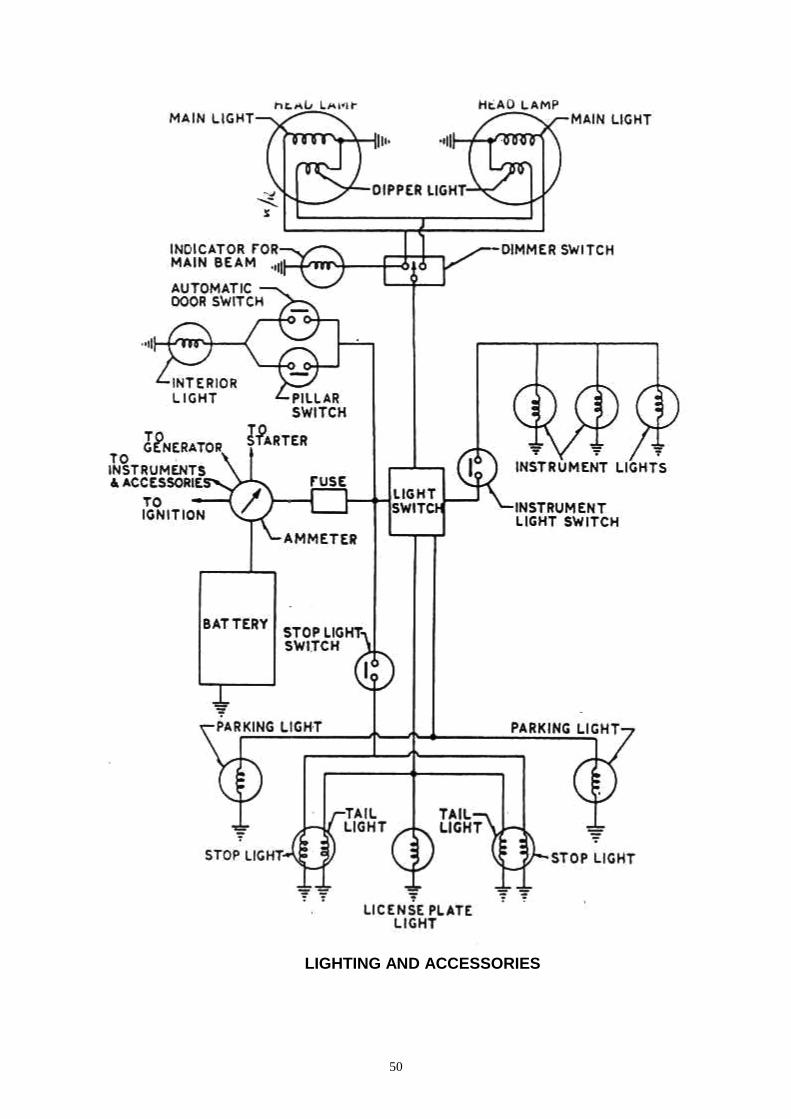
LIGHTING AND ACCESSORIES
51
If the current is not forced back in to the battery from some external source like the automobile generator, the battery would soon get discharged and it would not be in a position to deliver any more current.
Its main job in the automobile is to supply electric energy for cranking the engine and also to other electric units of the vehicle when the engine is not driving the generator, at a speed sufficient to produce the needed current. The battery also helps in balancing the voltage in the system.
c) Regulator:
There is also a regulator fitted on the automobile, which regulates the current produced by the generator. If there had been no regulator, The current produced by the generator would have been so much that it would have damaged the battery and other electrical units of the vehicle. High electric current is permitted to flow by the regulator when the battery is in a discharged condition or when the vehicle’s electric units are turned on. It helps in reducing the current produced by the generator when the battery is in a charged condition or when the electric units are switched off. It is essential to have some conducting path for distributing the electric energy from the source to the different points of utilizations. For this purpose, the generator and the battery are connected by means of conductors, and likewise the other units like the lamps, the starter, the horn, and the wipers. Etc. is connected to the battery.
2. Starting System:
In present-day automobiles, the method of starting the vehicle by hand has been replaced by that of the cranking motor. The cranking motor is a special kind of direct current electric motor. It is designed for intermittent service under great overload. It is of a high starting torque type and generally of the four-pole series type. It is clear that when the switch is closed. The current is directed to the cranking motor from the battery. The motor is provided with a pinion, which is made to mesh with a larger gear integral with the flywheel of the engine. The electric circuit is completed through earthed terminals, thus making the crankshaft of the engine to rotate until the engine starts. When the engine starts, the automatic device in the starter pinion disconnects the pinion from the flywheel gear ring when the starting switch is switched off.
3. Ignition System:
The ignition system plays an important role in the operation of petrol engines. It provides high voltage surges, from 4000 to 20000 V, at accurately timed intervals for the purpose of igniting the mixture of petrol and air compressed inside the cylinders of the engine. It may appear to be a simple matter but careful consideration will show that the duty of the ignition apparatus is quite different and exacting.
The electric ignition system is not deployed by diesel engines since the air temperature is sufficient at the end of the compression stroke to cause burning of the fuel, which is injected at that time. However, in the case of pre-combustion chamber diesel engines, it is essential to make use of special plugs known s glow plugs to heat the air at the time of starting the engine when it is cold.
Another method of igniting the petrol-air mixture is with the help of a magneto. It does not require battery current and therefore it does not need any special low-voltage circuit. The magneto generates its own low-voltage current. It produces the
52
high-voltage surges required for igniting the charge from this low-voltage current. It consists of an armature with windings, a permanent magnet and a contact breaker.
When the magneto shaft is rotated, it produces very rapid changes of magnetic flux linked with the armature windings resulting in a series of high-voltage surges. A succession of sparks is caused by these high-voltage surges. In the magneto, the basic source of energy is the permanent magnet. Since the spark energy is created by rotation, it is amply clear that this will increase with increase in speed. Spark energy actually increases rapidly from zero to medium speeds and then it remains fairly constant.
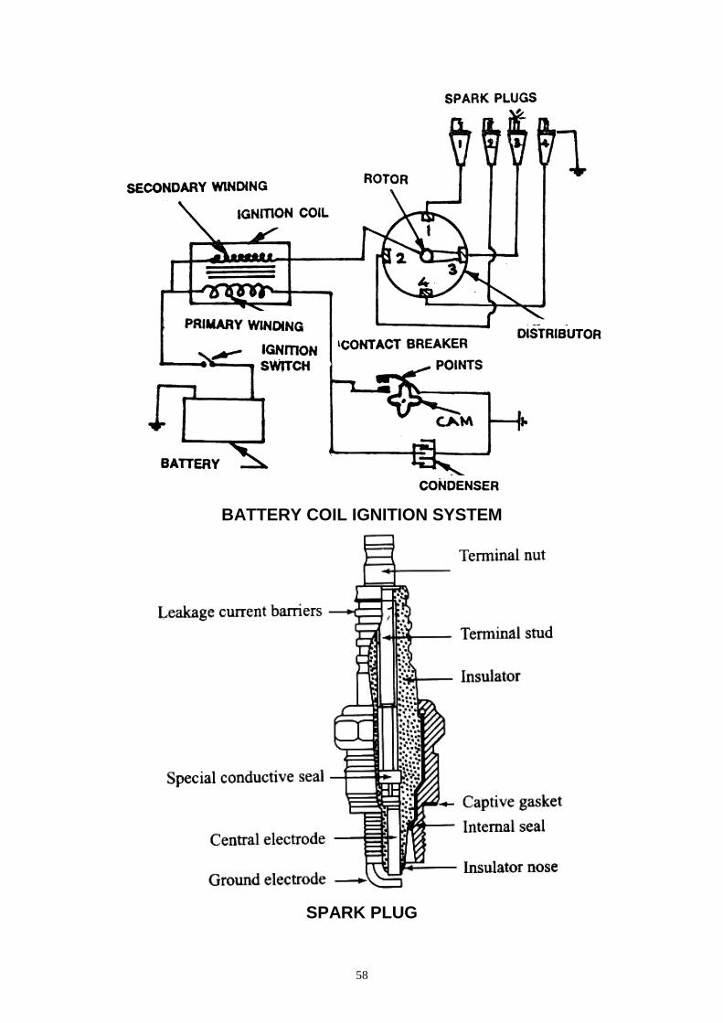
A simple circuit diagram of the coil ignition system. Battery B supplies a low voltage current via ammeter A and ignition switch S to the primary windings of the ignition coil. The ignition coil converts the low-voltage current of the battery to high-voltage current for producing sparks inside the cylinder to ignite the mixture. The current from the low-tension circuit of the ignition coil flows from the outlet terminal to the contact-breaker CB and then back to the battery through the earth. The contact-breaker CR is meant to make and break the low-voltage circuit every time a spark is required at the spark-plug electrodes.
The high-tension lead from the central terminal of the ignition coil is lead to the upper part of the distributor 1), which further distributes the high-tension current to each of the spark plugs in turn in case of a multi-cylinder engine. It is worth noting that the current consumption of the ignition coil is of the order of 3 5-4.5 A with a 12 V battery when the contact points are closed and the engine is at Test. The value falls to about one-half of these when the engine is running.
4. Lighting System:
The lighting system comprises the lamps used for warning purposes, the pilot lights, indicators and lights for illumination purposes The main lamps include the head-lamps, the tail and the number plate lamps, the direction-indicator lamps, the car panel and illumination lamps, the beam indicator lamp, the oil pressure warning lamp. Ignition warning lamp, etc,. The complete lighting circuit consists of a number of individual circuits for a single lamp or pair of lamps, each with its own switch, lives connection and earth connection. Seine of the accessories like the horn, the wiper, the car-heater and the radio are included in this diagram. They are all connected in parallel across the battery terminals. The battery supplies current through the ammeter to the lighting circuits. These circuits get their supply of current irrespective of whether the ignition switch is ON or OFF. In most automobiles they are protected by a single fuse F1 of 40-50 A capacity.
5. Accessories:
Some reference has been made to the various electrical accessories fitted in a vehicle in the section on the lighting system. The electrical components like the horn, the windscreen wipers, the radio, the car-heater, the electric pump, the oil pressure gauge, and the temperature gauge. The fuel level gauge, the ammeter, the impulse tachometer, the speedometer, etc., all fall under this section. Their detailed discussion will follow in subsequent chapters.
RESULT:
Thus the given service manual is studied.
53
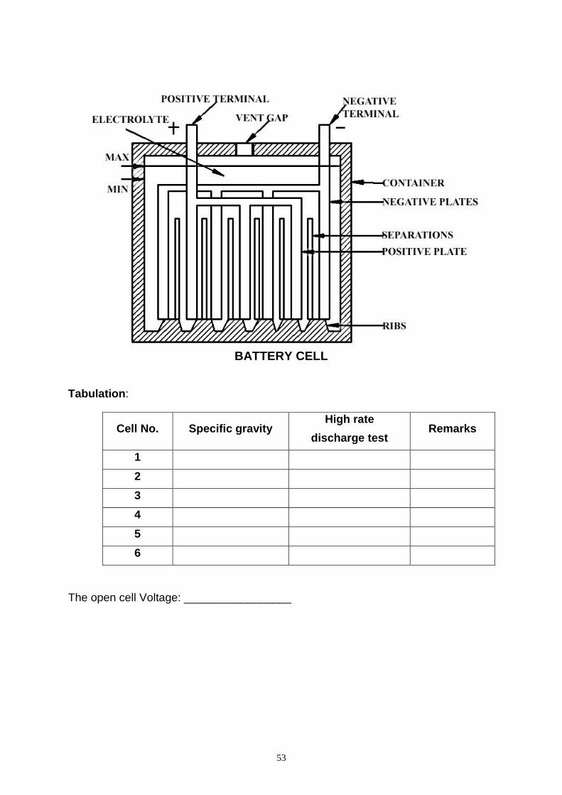
BATTERY CELL
Tabulation:
Cell No. Specific gravity High rate
discharge test Remarks
1
2
3
4
5
6
The open cell Voltage: _________________
54
EX. NO: DATE:
TESTING THE BATTERY
(Hydro meter test, open circuit voltage and high rate discharge testing)
AIM:
To test the given battery using specific gravity test, open circuit voltage and
high rate discharge test.
TOOLS & EQUIPMENT:
Set of spanners, screw drives cloth, high rate discharger, and hydrometer.
PROCEDURE:
a) Remove the battery form the car:
The battery terminals and boxes are cleaned well with distilled water. The battery connectors must be free form sulphate deposited. The connector bolt is removed and the terminal is removed. Heavenly blows should not be given on terminals, which lead to breakage of leg. After removing terminals the battery is transferred to work table. The filler caps are removed and cleaned in salt less water. Vent holes are also cleaned. Then all filler caps are cleaned is distilled water.
b) Inspection of electrolyte:
First of all filler caps are removed from the battery. Check the electrolyte level if it below with marking level adds distilled water.
c) Testing of battery:
A battery can be tested to as certain its condition by the following tests.
i) Specific gravity test:
When a fully charged battery is discharged, water is formed and so the specific gravity falls. The state of charge is proportional to specific gravity. It is checked by hydrometer syringe as shown in the figure. The hydrometer syringe is inserted into one cell and rubber bulb is pressed and released. Due to the vacuum in the syringe electrolyte will get filled up in the tube, mapping the lift with the electrolyte level. This float has marking provided on it, the syringe is lifted parallel to the eye and marking is noted, from the reading the state of charge of battery can be found out.
Battery condition Specific gravity
Fully charge 1.230
Half charge 1.220
Dead charge 1.150
55
ii) High rate discharge test:
The specific gravity will give correct reading as for as the battery is in good
condition. But when battery acid is happened to change specific gravity test shall
give wrong reading. Therefore high rate discharge test is conducted for each cell.
This test has a voltmeter fitted on its two pointed rods. In between rods a resistance
is also connected. Note the reading. The pointed ends of tester are pressed on the
terminals of each cell and the reading in voltmeter noted. The tester should not be
pressed for more than 5 seconds. For a good condition the reading must be
between 1.7V to1.9 V. If the reading is less, the fault must be investigated and made
it clear. If the difference of cell voltages of various cell should not be exceed 0.2V;
otherwise the battery may be taken to be defective.
iii) Open Voltage Test:
If the battery is just charged, the “Surface charge” must be removed from the
battery by running on the headlights for one minute, turning off, and waiting the for
about two minutes. Then connect the voltmeter to battery terminals. In case of 12V
battery, if the voltmeter reading is 12.6V, it is fully charged. If it is 12.2V it is half full
charged while below 11.9V it may be fully discharged. It has been observed that a
change of 0.01V of open circuit voltage is equivalent to a change of 0.010 in specific
gravity of the electrolyte.
RESULT:
Thus the specific gravity, high rate discharge test and open voltage test are done for the given battery.
56
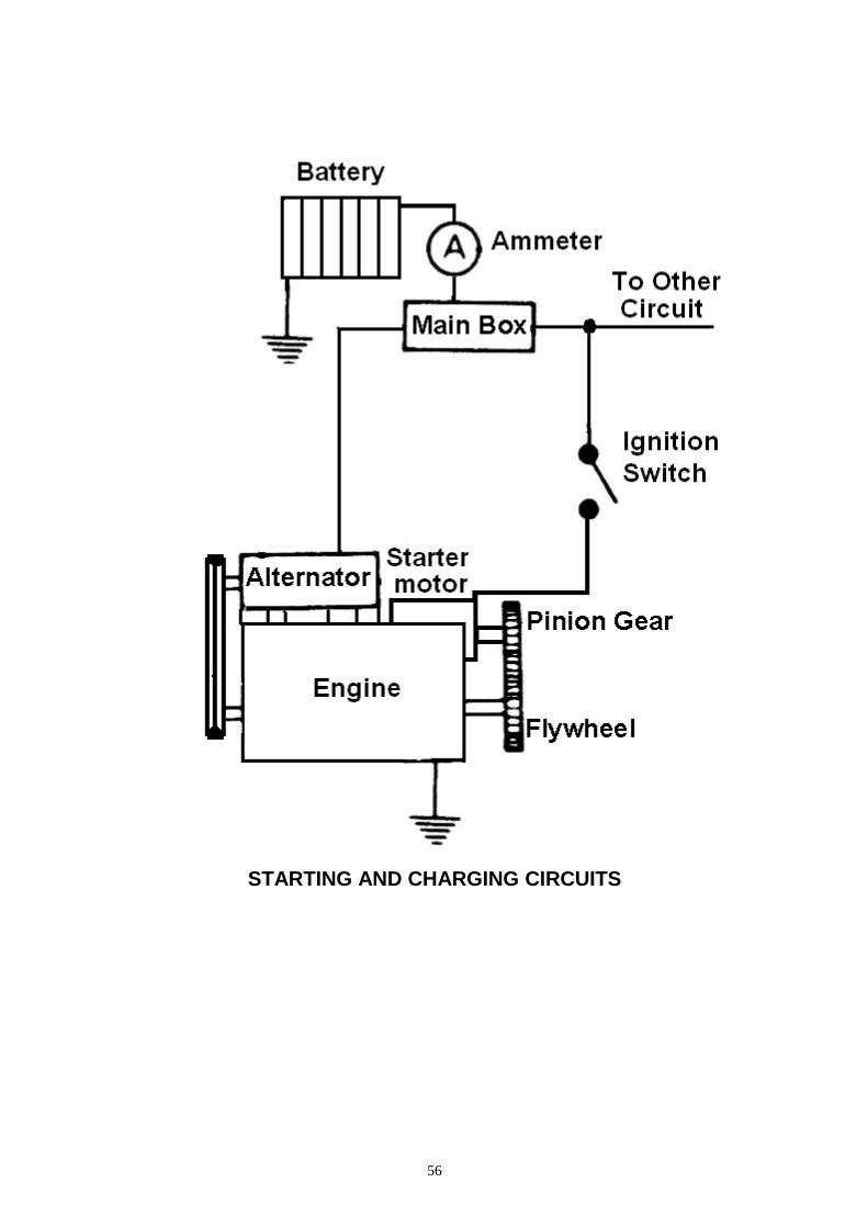
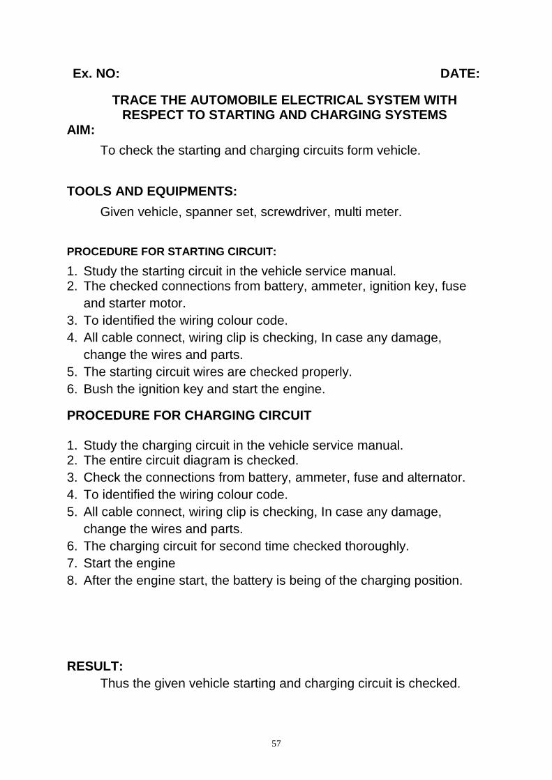
STARTING AND CHARGING CIRCUITS
57
Ex. NO: DATE:
TRACE THE AUTOMOBILE ELECTRICAL SYSTEM WITH RESPECT TO STARTING AND CHARGING SYSTEMS
AIM:
To check the starting and charging circuits form vehicle.
TOOLS AND EQUIPMENTS:
Given vehicle, spanner set, screwdriver, multi meter.
PROCEDURE FOR STARTING CIRCUIT:
1. Study the starting circuit in the vehicle service manual. 2. The checked connections from battery, ammeter, ignition key, fuse
and starter motor.
3. To identified the wiring colour code.
4. All cable connect, wiring clip is checking, In case any damage,
change the wires and parts.
5. The starting circuit wires are checked properly.
6. Bush the ignition key and start the engine.
PROCEDURE FOR CHARGING CIRCUIT 1. Study the charging circuit in the vehicle service manual. 2. The entire circuit diagram is checked.
3. Check the connections from battery, ammeter, fuse and alternator.
4. To identified the wiring colour code.
5. All cable connect, wiring clip is checking, In case any damage,
change the wires and parts.
6. The charging circuit for second time checked thoroughly.
7. Start the engine
8. After the engine start, the battery is being of the charging position.
RESULT:
Thus the given vehicle starting and charging circuit is checked.
58
BATTERY COIL IGNITION SYSTEM
SPARK PLUG
59
Ex. NO: DATE:
TRACE THE AUTOMOBILE ELECTRICAL SYSTEM WITH RESPECT TO BATTERY COIL IGNITION SYSTEM
AIM:
To learn various components of ignition system and dismantle, assemble of a distributor, set contact breaker points and service of spark plugs.
TOOLS AND EQUIPMENTS:
Petrol Engine, spanner set, screwdriver, multi meter, feeler gauge, vernier caliper, spark plug cleaner
PROCEDURE:
There are two basic circuits in battery ignition system.
a) Primary circuit
1) Battery
2) Primary winding of the ignition coil
3) Condenser and the contact breaker
b) Secondary circuit
1) Secondary winding of ignition coil
2) Distributor
3) Spark Plugs.
1) Ignition coil:
(i) Sparking performance test:
The purpose of this test is to see if the ignition coil is capable of producing high voltage surges forceful enough to fly good spark at the ignition coils at all times, particularly when its ignition temperature has raised to the normal operating level. Use of the electro tester is assumed for this test. With the ignition coil connected to the tester, let the spark fly across the three-needle gap. Continue of this testing for about three minutes so that the coil will get warm to simulate the normal operating condition. The coil may be deemed to be in good condition if the sparking is stable, without any misses. In the use of the electro tester for this purpose, do not enlarge the three-needle gap wider than 7mm.
2) Distributor
a) Distributor cap:
Leakage of high-tension energy for ignition shows up as misfiring in the engine. It occurs at any part of the high-tension line where insulation has failed or in a dirty distributor cap, that is, an internally dirty cap. A wider spark gap in the plug, a condition often found in poorly cared spark plugs, promotes the tendency of high-tension energy to find a short cut to ground. Cleanliness is very important for the distributor cap.
When a clean dry cloth, wipe off dust, if any and inspect for any damaged (scarred, scratched, or cracked) part of any part evidencing high-tension leakage inside the cap. Be sure to replace such parts.
60
b) Distributor Driven Gear:
Inspect the gear teeth for wear, and see if the backlash is normal or not. Excessive backlash can be told by turning the shaft back and forth, with its driven gear in mesh with driving gear. Mat-adjusted ignition timing is often due to excessive tooth wear in this gearing and, in such a case, can be corrected by replacing the driven gear.
c) Contact breaker point faces:
In the contact breaker, push the breaker arm with your fingertip just a little so that you can see the point faces. If the faces are oily, clean; if roughened, smoothen by grinding. In most cases, the point faces can be re-conditioned by grinding with a file or oilstone. Points worn beyond repair must be replaced, The illustration, below, tells what must be done in each case but the last one showing a pair of properly aligned, smooth faces. Wear or burning is hard to occur in the contact point whose point faces are in the condition labeled “good”.
d) Contact breaker gap and its setting:
The contact breaker gap should be between 0.35 to 0.45 mm. In case the gap is too small the spark is retarded. If the gap is too large the spark is advances. This gap s adjusted by using dial gauge or feeler gauge or dwell meter. The engine is cracked and distributor cap removed, till the breaker cap is maximum. The gap is then checked by means of feeler gauge. If it is not correct, the screws on the carrying stationary points are loosened by means of a screw driver and the plate adjusted so that the gap as measured by the feeler gauge is correct.
The dial gauge is clamped on the body of the distributor and the lever arm is made to rest on the moving arm at the back of the contact point. The engine is cranked so that gap is then reduced to zero. The dial gauge is then adjusted to bring the gauge pointer to zero position. The engine is cranked again to open the contact points to maximum gap size. The reading of the dial gauge is gives the gap size. It is adjusted, as already explained above. Dwell meter is an electronic instrument for measuring contact breaker point gap in terms of dwell. Dwell meters are connected to the negative side of the ignition coil to sense the opening and closing of the contact points. The other lead of dwell meter is usually connected to some good engine ground.
3) Spark Plug:
The sparking plug provides the gap across which the high-tension current jumps to give the spark for ignition of the petrol-air mixture. This gap should always be as recommended by the vehicle manufacturer.
a) Regular inspection and economical life:
A spark plug has a limited service life, deteriorating gradually, even if it is used correctly.
Its service life is shortened by incorrect selection, overheating and fouling from other than the spark plug itself. As a spark plug nears the end of its service life, its wastes fuel and loads the ignition system, causing deterioration in engine performance and increasing the pollution content of the exhaust gases. Regular inspection, every 5,000 km is recommended.
61
b) Cleaning procedure by spark plug cleaner:
i) Cleaning:
It is desirable to set up ground electrode using tool before cleaning. If spark plug is cleaned without setting up electrode, it cannot be cleaned enough because electrode makes a shadow on the insulator tip. If the insulator tip of the spark plug is wet or moist, it is better to clean it with gasoline and dry it before cleaning. Insert the firing end of the spark plug into the rubber adopter at the top of the cleaner down to the gasket seat. Lightly hold down on the plug terminal with the fingertip, and push down the button to blast the cleaning compounds onto the firing end. When the compressed air is released and sand blasting begins, rotate the fingertip so that the cleaning compounds will be distributed all over the firing end. Then push down the button for the air blast to remove the remaining cleaning compounds from the firing end.
ii) After treatment:
After cleaning, check for cracks on the firing end of the insulator. Cracks hidden by accumulated deposits some times appear after cleaning. Then, clean the thread and metal shell with a brass wire brush, and wipe the insulator at the top with clean and dry cloth.
iii) Reforming electrodes:
If centre electrode is worn out, the tip of centre electrode evenly to make a sharp edge. Be careful not to file too much off the centre electrode. Remove the shavings.
iv) Adjusting gap and replacing gasket:
Adjust the spark gap to the dimension specified by the engine manufacturer. If the gasket is deteriorated or lost, replace it with a new one. Gap adjustment is required when the gap grows over 0.2 mm more than the initial.
C) Installation:
Tighten the spark plug finger tight first, till the gasket reaches the cylinder head. Then screw about half -3/4 turn more with a plug wrench; if a new gasket attached, either excessive tightness or looseness will be a cause of trouble. Looseness sometimes, causes pre-ignition because heat cannot escape. On the other hand, excessive tightness damages the threads of both the cylinder head and spark plug.
RESULT:
The components in the ignition system are identified. Distributor and spark plugs are serviced.