Embed Size (px)
Citation preview

AutomationML Logic Description

2
Overview about AutomationML
AutomationMLEngineering data
CAEX IEC 62424 Top level format
Plant topology
information
•Plants
•Cells
•Components
•Attributes
•Interfaces
•Relations
•References
COLLADA
Geometry
Kinematics
PLCopen XML
Behaviour
Sequencing
Object A
Object A1
Object A2
InitInit
Step 1
End
Further XML Standard format
Further aspects of
engineering information
Object An
…

3
AutomationMLLogic data
AutomationML Internal Element
Logic information covered by AutomationML
Distinction between three types of information
„Sequencing“ of automation systems
„Behaviour“ of components
„Interlocking“ as description of necessary safety related conditions
One system component may contain each type of information
Behaviour
Sequencing
Interlocking
Robot
State 1
State 1.1
Event 1 / [Guard 1]
State 1.2
Event 2State 1.3
Event 3 / [Guard 3]
State 1.3
Event 2
State 2
State 3
Entrance Activity 2
Activity 3
Exit Activity 4
Event 4 / [Guard 5]
Guard 2 / Activity 1
HEvent 4 / [Guard 4]
Event 5
Event 6
[Guard 6]
C
[Guard 6.1]
[Guard 6.2]
Id Name
1 Handover to HTR002 0 4 4
2 Move to Lift Position 1 4 3 7
3 Lift skid 2 7 2 9
4 Lower skid 7 23 4 27
5 Move to end of 110HTR002 4 27 7 34
6 Initialise Robot 1 0 6 6
7 Execute Manufacturing Robot 1 3, 6 9 9 18
8 Postprocess Robot 1 7 18 4 22
9 Initialise Robot 2 6 6 4 10
10 Execute Manufacturing Robot 2 7, 9 18 5 23
11 Postprocess Robot 2 10 23 3 26
Sequence 2
Prede-
cessor
Start
time
End
time
Dura-
tion0 5 10 15 20 25 30 35 40 45 50 55 60 65 70 75 80 85
>=1
>=1
Var1
Var4
Var3
Var2
Var5&

4
Logic Information covered by AutomationML
Representative selection of model types
Behaviour: e.g. State Charts, Sequence Function Charts
Sequencing: e.g. Gantt, Impulse Diagrams, Sequence Function Charts
Interlocking: e.g. Logic Networks
Storage of logical information based on PLCopen XML
Usage of PLCopen XML Version 2
Sequencial Function Charts (SFC) for Sequencing and Behaviour
Function Block Diagrams (FBD) for Behaviour and Interlocking
Seamless integration into AutomationML top level format by
Referencing of PLCopen XML documents
Referencing of PLCopen XML variables
5
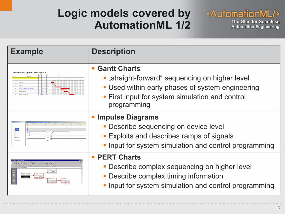
Logic models covered by AutomationML 1/2
Example Description
Gantt Charts
„straight-forward“ sequencing on higher level
Used within early phases of system engineering
First input for system simulation and control programming
Impulse Diagrams
Describe sequencing on device level
Exploits and describes ramps of signals
Input for system simulation and control programming
PERT Charts
Describe complex sequencing on higher level
Describe complex timing information
Input for system simulation and control programming
O PER ATIO N Seconds
D escription
<N r.> <Action>
1 Lower sk id 4,0 4,0
2 Stop L ift 1 4,0 1,0 5,0
3 U nlock Sk id 2 5,0 1,0 6,0
4 M ove to end of 110H TR 002 3 6,0 7,0 13,0
5 H andover to 120R F_002 over 120R FB001 4 13,0 12,0 25,0
6 M ove on 110H TR 002 4 13,0 5,0 18,0
7 M ove on 120R F_002 6 18,0 5,0 23,0
8 M ove on 120R FB001 7 23,0 2,0 25,0
9 M ove over to 120R F_003 5,7 25,0 6,0 31,0
Sequence diagram - Transport 2
System part
0 5 10 15 20 25 30 35 40 45 50 55 60 65 70 75 80 85

6
Logic models covered by AutomationML 2/2
Example Description
Sequence Function Charts (SFCs)
Describes sequencing and control implementations
Executable description
Near to PLC implementation
State Charts
Describes complex behaviour of mechatronical units
Not executable at PLC
required for virtual commissioning
Logic Networks
Describes interlocking information
Provides structures for state description
Near to PLC implementation
>=1
>=1
Var1
Var4
Var3
Var2
Var5&
State1
[Guard3]
[Guard2]
State3.2
State3.1
[Guard2] [Guard2]
State3
State2.2State2.1
State2
[Guard3]

7
Challenge transformation of
different logic models
IML
Transformation to
AutomationML
Logic Models PERT
Impulse
Gantt
…

8
History of PLCopen XML
1992 PLCopen was founded
One main activity is to develop and promote
the IEC 61131-3 standard
Other activities in the scope of function block
technologies, motion and safety
2002 Work of TC6 PLCopen XML started
Aim is the definition of a data exchange format for PLC programs
Uses XML as basis for the data format
2005 First Version of PLCopen XML was published
2008 Version V2.0 of PLCopen XML Specification
GlobalID Concept
Extension with user defined data possible
9
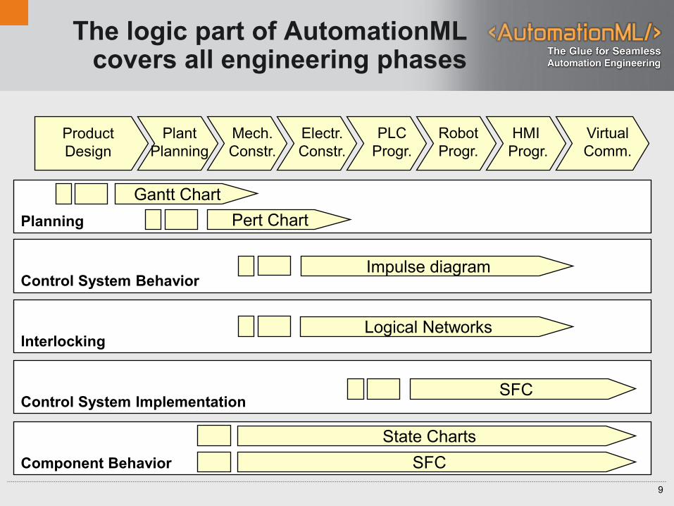
The logic part of AutomationML covers all engineering phases
Planning
Control System Behavior
Interlocking
Control System Implementation
Component Behavior
Product
Design
Plant
Planning
Mech.
Constr.
Electr.
Constr.
PLC
Progr.
Robot
Progr.
HMI
Progr.
Virtual
Comm.
Gantt Chart
Pert Chart
Impulse diagram
Logical Networks
SFC
State Charts
SFC
10
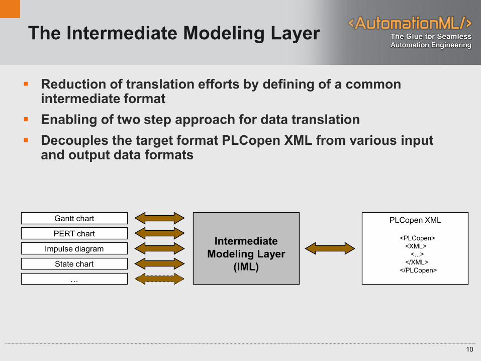
The Intermediate Modeling Layer
Reduction of translation efforts by defining of a common intermediate format
Enabling of two step approach for data translation
Decouples the target format PLCopen XML from various input and output data formats
Intermediate
Modeling Layer
(IML)
PERT chart
Impulse diagram
State chart
…
Gantt chart PLCopen XML
<PLCopen>
<XML>
<...>
</XML>
</PLCopen>
11
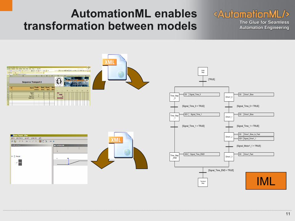
AutomationML enables transformation between models
[Signal_Motor1_1 = TRUE]
[Signal_Time_0 = TRUE]
[Signal_Time_1 = TRUE]
[Signal_Time_0 = TRUE]
[Signal_Time_1 = TRUE]
Drive1_0
D0 Drive1_Slow
Drive1_2
D0 Drive1_Slow_to_Fast
SD1 Signal_Drive1_1
Drive1_1
D0 Drive1_Slow
Drive1_3
D0 Drive1_FastTime_Step
_END
SD2 Signal_Time_ENDf
Time_Step
_1
SD1 Signal_Time_1
Time_Step
_0
D0 Signal_Time_0
[Signal_Time_END = TRUE]
Terminal
Step
Initial
Step
[TRUE]
IML
12
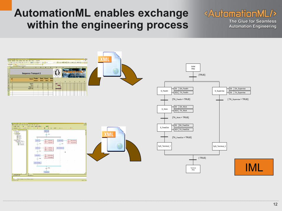
AutomationML enables exchange within the engineering process
[TA_FeedIn = TRUE]
[TA_Work = TRUE]
D0 DA_Supervise
D0 DA_FeedOut
D0 DA_Work
D0 DA_FeedIn
[ TRUE]
Terminal
Step
[TRUE]
SD2 TA_FeedIn
SD3 TA_Work
SD1 TA_FeedOut
[ TA_Supervise = TRUE]
D0 TA_SuperviseS_Supervise
S_FeedOut
S_Work
Initial
Step
SyS_Terminal_1 SyS_Terminal_2
S_FeedIn
[TA_FeedOut = TRUE]
IML

13
Interlocking with AutomationML
Interlocking information is used to describe states which:
Are prerequisite for special actions
Must not be violated during special actions
Require a stop of running actions
The interlocking description can be used for:
Safety information
Behaviour information of components
In combination with Sequencing and Behaviour information

14
Three levels of interlocking description
Level 1: Signal and component groups
Level 2: Boolean logic networks for signal groups
Level 3: Complex logic network elements
Emergency stop 1
Light guard 1
Emergency stop 2
Robot 2
Welding tool 1
Gate 1
Signal groupComponent
group
ANDVar1
Var3
Var2 interlockingSignal
POU 3
POU1
POU2
Min
Max
Temp
LIMIT_INT INT_TO_BOOLOut_POU2MN
IN
MX

15
Example: Sequence Planning for a Daimler real life cell (1/3)
Microsoft Excel, Logic CPF

16
Example: Sequence Planning for a Daimler real life cell (2/3)
AutomationML Logic Viewer

17
Example: Sequence Planning for a Daimler real life cell (3/3)
jPlan, Logic CPF
18
Summary AutomationML logic part
The logic description is an integrated part of AutomationML
Supports most used graphical models
Enables transformation of models from early Gantt charts to SFCs close to PLC code
The storage of logic information is based on PLCopen XML 2.0

19
Join AutomationML!
http://www.automationml.org


![ANDEROID MOBILE PHONE CONTROLLED … · Pin 7 = Logic 1 3. Pin 2 = Logic 0 and | Idle [No rotation] ... When microcontroller detects “A” the robot/robot car ... The programming](https://img.dokumen.tips/doc/110x75/5ac5045c7f8b9a220b8d1ff9/anderoid-mobile-phone-controlled-7-logic-1-3-pin-2-logic-0-and-idle-no.jpg)


![[ENG] Visual Logic Robot Programming](https://img.dokumen.tips/doc/110x75/577c78891a28abe05490454f/eng-visual-logic-robot-programming.jpg)