Embed Size (px)
Citation preview

TABLE OF CONTENTS
TABLE O
F CO
NTENTS
©2011 Maverick Performance, Inc. See inside rear cover of catalog or visit web site for limited warranty and venue provision.
Standard Shifter . . . . . . . . . . . . . . . . . . . . . . . . . . . . . . . . . . . . .2-3
Lockout Shifter . . . . . . . . . . . . . . . . . . . . . . . . . . . . . . . . . . . . . .4-5
Gate Plates . . . . . . . . . . . . . . . . . . . . . . . . . . . . . . . . . . . . . . . . .6-7
Shifter Accessories . . . . . . . . . . . . . . . . . . . . . . . . . . . . . . . . . . .8-9
Conversion Kits . . . . . . . . . . . . . . . . . . . . . . . . . . . . . . . . . . .10-11
Shifter Exploded Views . . . . . . . . . . . . . . . . . . . . . . . . . . . . . .12-13
Turbo-Hydro 400 Valve Body . . . . . . . . . . . . . . . . . . . . . . . . .14-16
C-6 Manual Valve Body . . . . . . . . . . . . . . . . . . . . . . . . . . . . . . . .17
C-4 Manual Valve Body . . . . . . . . . . . . . . . . . . . . . . . . . . . . . . . .18
Valve Body Separator Plates & Gaskets . . . . . . . . . . . . . . . . . . . .19
Powerglide Planetary Carrier . . . . . . . . . . . . . . . . . . . . . . . . .20-23
Planetary Carrier Gear Sets . . . . . . . . . . . . . . . . . . . . . . . . . .24-25
Extension Housing . . . . . . . . . . . . . . . . . . . . . . . . . . . . . . . . . . . .26
Housings & Shafts . . . . . . . . . . . . . . . . . . . . . . . . . . . . . . . . . . . .27
Powerglide Components . . . . . . . . . . . . . . . . . . . . . . . . . . . . . . .28
Powerglide Band Apply . . . . . . . . . . . . . . . . . . . . . . . . . . . . . . . .29
Powerglide Drive Assembly . . . . . . . . . . . . . . . . . . . . . . . . . .30-31
Turbo-Hydro 400 Accessories . . . . . . . . . . . . . . . . . . . . . . . . .32-33
Components . . . . . . . . . . . . . . . . . . . . . . . . . . . . . . . . . . . . . . . .34
Clutch Hydro Kit . . . . . . . . . . . . . . . . . . . . . . . . . . . . . . . . . . . . . .35
Clutch Flite Kit . . . . . . . . . . . . . . . . . . . . . . . . . . . . . . . . . . . . . . .36
Clutch C-6 Kit . . . . . . . . . . . . . . . . . . . . . . . . . . . . . . . . . . . . . . . .37
Components . . . . . . . . . . . . . . . . . . . . . . . . . . . . . . . . . . . . . . . .38
Shifter Installation Instructions . . . . . . . . . . . . . . . . . . . . . . . .39-51
Drive Assembly Installation Instructions . . . . . . . . . . . . . . . . . . . .52
Maverick offers a wide array of options that enable you to customize your purchase tobest suit your needs. You will see option numbers listed throughout this catalog. These are
intended to be used as a reference only. Option numbers apply to assemblies only.Individual parts must be ordered by part number, not option number.
STANDARD SHIFTER
2©2011 Maverick Performance, Inc. See inside rear cover of catalog or visit web site for limited warranty and venue provision.
OPTION 9103Universal Mount
Side PlatesOPTION 8258Switch Mount
Console
OPTION 8257Competition Shifter
SHIFTER
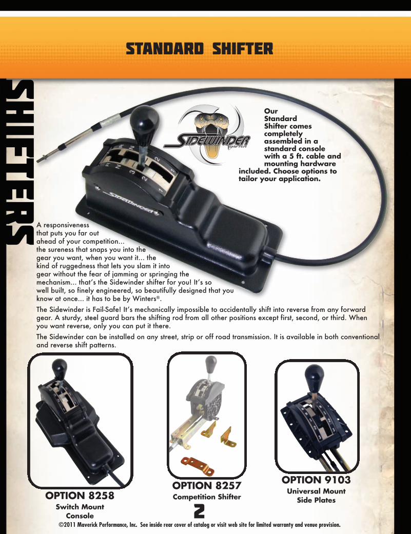
S A responsivenessthat puts you far outahead of your competition...the sureness that snaps you into thegear you want, when you want it... thekind of ruggedness that lets you slam it intogear without the fear of jamming or springing themechanism... that’s the Sidewinder shifter for you! It’s sowell built, so finely engineered, so beautifully designed that youknow at once... it has to be by Winters®.
The Sidewinder is Fail-Safe! It’s mechanically impossible to accidentally shift into reverse from any forwardgear. A sturdy, steel guard bars the shifting rod from all other positions except first, second, or third. Whenyou want reverse, only you can put it there.
The Sidewinder can be installed on any street, strip or off road transmission. It is available in both conventionaland reverse shift patterns.
OurStandardShifter comescompletelyassembled in astandard consolewith a 5 ft. cable andmounting hardware
included. Choose options totailor your application.

STANDARD SHIFTER
SHIFTERS
3©2011 Maverick Performance, Inc. See inside rear cover of catalog or visit web site for limited warranty and venue provision.
APPLICATION SHIFTER P/NTurbo-Hydro 400 Stock Shift Pattern (‘65 & Later) 107-1
Turbo-Hydro 400 Reverse Shift Pattern (‘65 & Later) 107-2
Turbo-Hydro 350 Stock Shift Pattern (‘69 & Later) 157-1
Turbo-Hydro 350 Reverse Shift Pattern (‘69 & Later) 157-2
700R4 & 4L60E Stock Shift Pattern 177-1
4L80E Stock Shift Pattern 187-1
Allison® LCT1000, 2000 & 2400 197-1
727 Torqueflite TF-8 Stock Shift Pattern (‘66 & Later) 207-1
American Motors Stock Shift Pattern (‘72 & Later) 207-1
727 Torqueflite TF-8 Reverse Shift Pattern (‘66 & Later) 207-2
American Motors Reverse Shift Pattern (‘72 & Later) 207-2
904 & 999 Torqueflite TF-6 Stock Shift Pattern 257-1
904 & 999 Torqueflite TF-6 Reverse Shift Pattern 257-2
Ford® C-6 Stock Shift Pattern (‘66 & Later) 307-1
Ford® C-6 Reverse Shift Pattern (‘66 & Later) 307-2
Ford® AODE & 4R70E Stock Shift Pattern 327-1
Ford® E4OD & 4R100 Stock Shift Pattern 337-1
Ford® C-4 Stock Shift Pattern (‘64 & Later) 357-1
Ford® C-4 Reverse Shift Pattern (‘64 & Later) 357-2
Powerglide Stock Shift Pattern 507-1
Powerglide Reverse Shift Pattern 507-2
Toyota® 607-1
DESCRIPTION OPTION P/NNot Assembled 8255
Competition Style 8257Switch Mount Console 8258
Safety Switch 8259
OPTIONS
See page 12 for componentsStock- Refers to PRN321 pattern
Reverse- Refers to PRN123 pattern
DESCRIPTION OPTION P/NCustom Logo 8260
Universal Mount 9103Cable Length 9110-XX
Substitute Gate Plate 9112-XXXX

LOCKOUT SHIFTER
4©2011 Maverick Performance, Inc. See inside rear cover of catalog or visit web site for limited warranty and venue provision.
OPTION 9103Universal Mount
Side PlatesOPTION 8258Switch Mount
Console
SHIFTER
S
OPTION 8257Competition Shifter
A responsivenessthat puts you far outahead of your competi-tion... the sureness that snaps youinto the gear you want, when you wantit... the kind of ruggedness that lets you slamit into gear without the fear of jamming or spring-ing the mechanism... that’s the Sidewinder shifter foryou! It’s so well built, so finely engineered, so beautifullydesigned that you know at once... it has to be by Winters®.
The Sidewinder is Fail-Safe! It’s mechanically impossible to accidentallyshift into reverse from any forward gear. A sturdy, steel guard bars the shifting rod from all other positionsexcept first, second, or third. When you want reverse, only you can put it there.
The Sidewinder can be installed on any street, strip or off road transmission. It is available in bothconventional and reverse shift patterns.
OurLockoutShifter featuresan extra mechanismthat must be pulled uptowards the knob in orderto shift in and out of thereverse and parkpositions.This shifter also includes a
safety switch that requires you to have theshifter in the park position in order tostart your vehicle.
These features satisfy sanctioningbody’s rules and regulations.

LOCKOUT SHIFTER
SHIFTERS
5©2011 Maverick Performance, Inc. See inside rear cover of catalog or visit web site for limited warranty and venue provision.
See page 13 for componentsStock- Refers to PRN321 pattern
Reverse- Refers to PRN123 pattern
APPLICATION SHIFTER P/NTurbo-Hydro 400 Stock Shift Pattern (‘65 & Later) 107-1B
Turbo-Hydro 400 Reverse Shift Pattern (‘65 & Later) 107-2B
Turbo-Hydro 350 Stock Shift Pattern (‘69 & Later) 157-1B
Turbo-Hydro 350 Reverse Shift Pattern (‘69 & Later) 157-2B
700R4 & 4L60E Stock Shift Pattern 177-1B
4L80E Stock Shift Pattern 187-1B
Allison® LCT1000, 2000 & 2400 197-1B
727 Torqueflite TF-8 Stock Shift Pattern (‘66 & Later) 207-1B
American Motors Stock Shift Pattern (‘72 & Later) 207-1B
727 Torqueflite TF-8 Reverse Shift Pattern (‘66 & Later) 207-2B
American Motors Reverse Shift Pattern (‘72 & Later) 207-2B
904 & 999 Torqueflite TF-6 Stock Shift Pattern 257-1B
904 & 999 Torqueflite TF-6 Reverse Shift Pattern 257-2B
Ford® C-6 Stock Shift Pattern (‘66 & Later) 307-1B
Ford® C-6 Reverse Shift Pattern (‘66 & Later) 307-2B
Ford® AODE & 4R70E Stock Shift Pattern 327-1B
Ford® E4OD & 4R100 Stock Shift Pattern 337-1B
Ford® C-4 Stock Shift Pattern (‘64 & Later) 357-1B
Ford® C-4 Reverse Shift Pattern (‘64 & Later) 357-2B
Powerglide Stock Shift Pattern 507-1B
Powerglide Reverse Shift Pattern 507-2B
Toyota® 607-1B
OPTIONSDESCRIPTION OPTION P/NNot Assembled 8255B
Competition Style 8257Switch Mount Console 8258
Custom Logo 8260Red Shift Knob 8261
DESCRIPTION OPTION P/NBlue Shift Knob 8262Universal Mount 9103
Cable Length 9110-XXSubstitute Gate Plate 9112-XXXX

GATE PLATES
SHIFTER
S
©2011 Maverick Performance, Inc. See inside rear cover of catalog or visit web site for limited warranty and venue provision.6
P
R
N
3
2
1
P
R
N
3
2
1
P
R
N
3
2
1
P
R
N
3
2
1
P
R
N
1
2
3
P
R
N
1
2
3
P
R
N
1
2
3
P
R
N
1
2
3
P
R
N
1
2
3
P
R
N
1
2
3
# DESCRIPTION P/N
1 Stock 1031
2 Reverse Pattern 1032
3 Rock Crawler Reverse Pattern 1032-1
4 Lockout Stock Pattern 1091
5 Lockout Reverse Pattern 1092
TURBO-HYDRO 400 & 350
1 2 3 4 5
1 2
TURBO-HYDRO 700R4, 4L60E, 4L80EALLISON® LCT1000, 2000 & 2400
# DESCRIPTION P/N
1 Stock 4013
2 Lockout Stock Pattern 4014
# DESCRIPTION P/N
1 Stock 6127
2 Reverse Pattern 6128
3 Lockout Stock Pattern 5583
4 Lockout Reverse Pattern 5584
POWERGLIDE
1 2 3 4
To Substitute Gate PlateAdd Option 9112-XXXX
to Shifter P/N.Example: P/N 107-1
9112-1032-1

GATE PLATES
SHIFTERS
7©2011 Maverick Performance, Inc. See inside rear cover of catalog or visit web site for limited warranty and venue provision.
P
R
N
3
2
1
P
R
N
1
2
3
P
R
N
1
2
3
P
R
N
1
2
3
P
R
N
1
2
3
P
R
N
3
2
1
P
R
N
3
2
1
P
R
N
3
2
1
P
R
N
1
2
3
P
R
N
1
2
3
1 2 3 4 5
# DESCRIPTION P/N
1 Stock 2027
2 Reverse Pattern 2028
3 Rock Crawler Reverse Pattern 2028-1
4 Lockout Stock Pattern 2091
5 Lockout Reverse Pattern 2092
P
R
N
3
2
1
P
R
N
3
2
1
P
R
N
3
2
1
P
R
N
3
2
1
P
R
N
1
2
3
P
R
N
1
2
3
P
R
N
1
2
3
P
R
N
1
2
3
P
R
N
1
2
3
P
R
N
1
2
3
1 2 3 4 5
# DESCRIPTION P/N
1 Stock 3014
2 Reverse Pattern 3015
3 Rock Crawler Reverse Pattern 3015-1
4 Lockout Stock Pattern 3091
5 Lockout Reverse Pattern 3092
727, 904 & 999 TORQUEFLITE TF-6 & TF-8 & AMERICAN MOTORS
FORD® C-6 & C-4
1 2
FORD® AODE, 4R70E, E4OD & 4R100
# DESCRIPTION P/N
1 Stock 3286
2 Lockout Stock Pattern 3287
To Substitute Gate PlateAdd Option 9112-XXXX
to Shifter P/N.Example: P/N 107-1
9112-1032-1

SHIFTER OPTIONS
SHIFTER
S
©2011 Maverick Performance, Inc. See inside rear cover of catalog or visit web site for limited warranty and venue provision.
Standard ConsoleP/N 5070
Switch Mount ConsoleP/N 1458Option 8258
Competition ShifterOption 8257
Console Mounted Dash Mounted
Universal Mount Shifter Side PlateP/N 6636-02
Option 9103
8
1
2
# DESCRIPTION P/N QTY1 Front Floor Mount Bracket 3088 22 Rear Floor Mount Bracket 3087 1
4”
2”
6 1/4”
15”
5 1/2” 7 3/4”

SHIFTER OPTIONS
©2011 Maverick Performance, Inc. See inside rear cover of catalog or visit web site for limited warranty and venue provision.
LENGTH P/N OPTIONLess Cable ------------- 9110-0
4 Foot 6014-48 9110-485 Foot (Standard) 6014-60 ------------
6 Foot 6014-72 9110-72
1
3
4
56
7
2
P/N 4712T (Standard Shaft)P/N 4712ST (Short Shaft)Option 9111T
Button Shifter Conversion KitsThese conversion kits feature a hollow shift shaft that provides the switch wires a convenient
path to the underside of the console.
# DESCRIPTION P/N QTY1 Aluminum Shift Knob 2100-02 12 “T” Style Shift Knob 2100-02T 13 Button 3573 14 Locknut 4668 15 Shaft, Standard, 5 3/8” 5941-02 15 Shaft, Short, 4 3/8” 5941-02S 16 #10-24 x 2 1/2” SHCS 7967 17 #10-24 Nylon Locknut 7968 1
Kit Includes:
9
P/N 4712 (Standard Shaft)P/N 4712S (Short Shaft)Option 9111
Available Cable LengthsOriginal style, heavy duty cables feature 1/4”-28” thread on both ends with 3” of travel.
SHIFTERS
LENGTH P/N OPTION8 Foot 6014-96 9110-9610 Foot 6014-120 9110-12012 Foot 6014-144 9110-14415 Foot 6014-180 9110-180

CONVERSION KITS & SAFETY SWITCH
SHIFTER
S
©2011 Maverick Performance, Inc. See inside rear cover of catalog or visit web site for limited warranty and venue provision.
46
5
5
6
3
2
1
# DESCRIPTION P/N QTY1 Contact Bracket 1087 12 Pal Nut 7951 13 Switch Bracket 1086 14 Safety Switch 1088 15 1/4-20 x 1/2” HHCS 7941 26 1/4” Flat Washer 7131 2
Kit Includes:
Safety SwitchKIT P/N 1089Option 8259Installed On ShifterThis safety switch operates in park only. Whenproperly installed, it requires the shifter to be in thepark position in order for the vehicle to be started.
SHIFTERP/N
GATEPLATE
HARDWAREKIT DECAL
107-1 1031 1095 6018-04107-2 1032 1095 6018-03157-1 1031 1595 6018-04157-2 1032 1595 6018-03177-1 4013 4095 6018-09187-1 4013 1495 6018-09197-1 4013 1195 6018-09207-1 2027 2095 6018-06207-2 2028 2095 6018-05257-1 2027 2795 6018-06257-2 2028 2795 6018-05307-1 3014 3095 6018-02307-2 3015 3095 6018-01327-1 3286 3495 6018-11337-1 3286 3395 6018-11357-1 3014 3595 6018-02357-2 3015 3595 6018-01507-1 6127 5595 6018-07507-2 6128 5595 6018-08
The Sidewinder Shifter can easily be converted from standard tolockout or visa-versa. Additionally, conversion to a different transmissionis easily accomplished by using Winters® gate plates and hardware kits.
Standard ShifterSHIFTERP/N
GATEPLATE
HARDWAREKIT DECAL
107-1B 1091 1095 6018-04107-2B 1092 1095 6018-03157-1B 1091 1595 6018-04157-2B 1092 1595 6018-03177-1B 4014 4095 6018-09187-1B 4014 1495 6018-09197-1B 4014 1195 6018-09207-1B 2091 2095 6018-06207-2B 2092 2095 6018-05257-1B 2091 2795 6018-06257-2B 2092 2795 6018-05307-1B 3091 3095 6018-02307-2B 3092 3095 6018-01327-1B 3287 3495 6018-11337-1B 3287 3395 6018-11357-1B 3091 3595 6018-02357-2B 3092 3595 6018-01507-1B 5583 5595 6018-07507-2B 5584 5595 6018-08
Lockout Shifter
10

LOCKOUT CONVERSION KIT
SHIFTERS
11©2011 Maverick Performance, Inc. See inside rear cover of catalog or visit web site for limited warranty and venue provision.
9
8
7
6
5
1
4
3
2
A. Remove old shaft and gate plate. Replace with new shifter shaft using #10-24 x 2 1/2” SHCS (#2) andlocknut (#3). DO NOT USE roll pin from old assembly.
B. Install new gate plate (#4).
C. Install lock-out sleeve assembly (#’s 5, 6, & 7). This sleeve must slide freely on the shifter shaft.
D. Install spring (#8) and then shifter knob (#9). After knob is in place, recheck the movement of the lock-outsleeve. It MUST slide freely on the shifter shaft.
APPLICATION KIT P/NTurbo-Hydro 350-400 Stock Shift Pattern 1490-01
Turbo-Hydro 350-400 Reverse Shift Pattern 1490-02Torqueflite 727, 904, 999 & American Motors Stock Shift Pattern 1490-03
Torqueflite 727, 904, 999 & American Motors Reverse Shift Pattern 1490-04Ford® C-4 & C-6 Stock Shift Pattern 1490-05
Ford® C-4 & C-6 Reverse Shift Pattern 1490-06Powerglide Stock Shift Pattern 1490-07
Powerglide Reverse Shift Pattern 1490-08Turbo-Hydro 700R4, 4L60E, 4L80E, Allison & Stock Shift Pattern 1490-09
Turbo-Hydro 700R4, 4L60E, 4L80E, Allison & Reverse Shift Pattern 1490-10Ford® AODE, 4R70E, E4OD, 4R100 Stock Shift Pattern 1490-11
Ford® AODE, 4R70E, E4OD, 4R100 Reverse Shift Pattern 1490-12
# DESCRIPTION P/N QTY1 Shifter Shaft 1097 12 #10-24 x 2 1/2” SHCS 7698 13 #10-24 Nylon Locknut 7968 14 Gate Plate 1
Turbo-Hydro Stock Pattern 1091Turbo-Hydro Reverse Pattern 1092
Torqueflite Stock Pattern 2091Torqueflite Reverse Pattern 2092
Ford® Stock Pattern 3091Ford® Reverse Pattern 3092
Ford® AODE & E4OD Stock Pattern 3287Turbo-Hydro 700R4 Stock Pattern 4014
Powerglide Stock Pattern 5583Powerglide Reverse Pattern 5584
5 Snap Ring 7670 16 Collar 1094 17 Lockout Sleeve 1093 18 Lockout Spring 1098 19 Shifter Knob (Specify Color) 1096 1
Kit Includes:
Black Knob Standard
Option 8261Red Knob
Option 8262Blue Knob
Converts Standard Shifter To Lockout Shifter

STANDARD SHIFTER EXPLODED VIEW
12©2011 Maverick Performance, Inc. See inside rear cover of catalog or visit web site for limited warranty and venue provision.
1
2
34
56
30
789
10
11
1213
19
20
22
14
23
24
29
25
28
31
2726
4
5621
14
10
15
17
18 20
19
1312
11
16
32
1334
3335
36
# DESCRIPTION P/N QTY1 Shifter Knob 2100 12 Shifter Shaft 5941 13 Nylon Bushing 7887 14 1/8” x 5/8” Roll Pin 7966 25 Detent Spring 1112 26 3/8” Detent Ball 7755 27 3/16” x 1 1/2” Roll Pin 7945 18 1/4” x 7/8” Rivet 7965 29 Cross Pin 6644 110 E-Clip 7671 211 Side Plate 6636 212 1/4” Int/Ext Tooth Lock Washer 7937 613 1/4-20 x 1/2” HHCS 7941 1014 Cable Control Side Plate 6648 215 Gate Plate See Pages 6-7 116 Gate Plate Retainer 6875 217 #10 Lock Washer 7128 418 #10-24 x 3/8” SHCS 7938 4
# DESCRIPTION P/N QTY19 Side Bracket 6643 220 Self-Clinching Nuts 7950 621 Clevis Pin 7888 122 Cotter Pin 7139 123 Clevis 6647 124 1/4-28 Jam Nut 7926 125 Cable See Page 9 126 #10-32 x 1/2” SHCS 7943 227 Cable Clamp 1312 128 Cable Clamp Shim 1313 129 #10-32 ESNA Lock Nut 7944 130 Shifter Shaft Housing 6637 131 Console 5070 132 Switch Mount Console 1458 133 Name Plate 6022 234 1/4” Washer 7131 4
35* Shifter Bracket (L Style) 3088 136* Shifter Bracket (U Style) 3087 1
* Optional Items
See page 3 for Kit Part Numbers
SHIFTER
S

LOCKOUT SHIFTER EXPLODED VIEW
SHIFTERS
13©2011 Maverick Performance, Inc. See inside rear cover of catalog or visit web site for limited warranty and venue provision.
# DESCRIPTION P/N QTY1 Shifter Knob 1096 12 Lockout Spring 1098 13 Lockout Sleeve 1093 14 Collar 1094 15 Snap Ring 7670 16 Shifter Shaft 1097 17 Nylon Bushing 7887 18 1/8” x 5/8” Roll Pin 7966 29 Detent Spring 1112 210 3/8” Detent Ball 7755 211 3/16” x 1 1/2” Roll Pin 7945 112 1/4” x 7/8” Rivet 7965 213 Cross Pin 6644 114 E-Clip 7671 215 Side Plate 6636 216 1/4” Int/Ext Tooth Lock Washer 7937 617 1/4-20 x 1/2” HHCS 7941 1218 Cable Control Side Plate 6648 219 Gate Plate See Pages 6-7 120 Gate Plate Retainer 6875 221 #10 Lock Washer 7128 422 #10-24 x 3/8” SHCS 7938 4
# DESCRIPTION P/N QTY23 Side Bracket 6643 224 Self-Clinching Nuts 7950 625 Clevis Pin 7888 126 Cotter Pin 7139 127 Clevis 6647 128 Contact Bracket 1087 129 1/4-28 Jam Nut 7926 130 Cable See Page 9 131 #10-32 x 1/2” SHCS 7943 232 Cable Clamp 1312 133 Cable Clamp Shim 1313 134 #10-32 ESNA Lock Nut 7944 135 Shifter Shaft Housing 6637 136 Safety Switch Bracket 1086 137 9/16” Pal Nut 7951 138 Safety Switch 1088 139 Console 5070 140 Switch Mount Console 1458 141 Name Plate 6022 242 1/4” Washer 7131 643* Shifter Bracket (U Style) 3087 144* Shifter Bracket (L Style) 3088 1
1
2
3
4
5
6
78
910
35
11
12
13
14
15
1617
42
17
23
24
26
18
27
29
28
34
30
33
3231
8
91025
18
14
19
21
22 24
23
1716
15
20
3837
36
1742
43
44
39
40
1742
41
* Optional Items
Shown Without Safety Switch (Page 10)See page 5 for Kit Part Numbers

TURBO-HYDRO 400 CONVERSION KIT
VALVE B
ODIES
14©2011 Maverick Performance, Inc. See inside rear cover of catalog or visit web site for limited warranty and venue provision.
Bottom - AP/N 1068
Separator PlateP/N 1048
Top - BP/N 1069
This hole must be in this gasket
This hole must be in this gasket Rectangular hole
RETAIN THIS CHECK BALL.REMOVE ALL OTHER CHECK BALLS.
Figure 1
Figure 2
B-Install P/N 1069 betweenseparator plate and transmission case.
KIT P/N 1082
A-Install P/N 1068 between valve body and separator plate.
DESCRIPTION P/N QTYTop Gasket 1069 1
Separator Plate 1048 1Bottom Gasket 1068 1Modulator Plug 1002 1Aluminum Plug 1028 1
Steel Plug 1027 1Manual Valve 1046 1
5/16” Ball 7398 1
Kit Includes:
Our redesigned valve body is intended for competition only —the shift pattern has been reversed to P R N 1 2 3.
1. The following parts should be removed from the transmission since their use is no longer necessary.A. Intermediate over-running band and apply servo partsB. Governor assemblyC. Governor supply tubesD. Replace the modulator with aluminum plug P/N 1002
(retain valve in bore).E. Remove all valve body check balls in case except one
shown in figure 1.F. Remove center lip seal in direct clutch packG. Park rod may be retained or removed at your option.
2. Punch out accumulator guide pin in valve body casting.3. Install furnished 5/16” ball, P/N 7398, in shortest governor
passage (closest to manual valve).4. Substitute modulator on side of transmission case
with modulator plug, P/N 1002 (furnished).5. Top and bottom valve body gaskets are different —
It is imperative that they be put in their proper positions.Compare to drawings below to make certain that holes noted are in gaskets supplied.Note the difference in figure 2. ‘B’ gasket must be installed between the main case and the separator plate.

TURBO-HYDRO 400 CONVERSION KIT
VALVE BODIES
15©2011 Maverick Performance, Inc. See inside rear cover of catalog or visit web site for limited warranty and venue provision.
Del
ete
thes
e part
s and
tap in
to it
's p
lace
,3
/8"
dia
. ro
d P
/N 1
02
7 (
furn
ishe
d),
so r
emain
ing p
art
s ca
n be
inst
alle
d.
* Reu
se d
eten
t sp
ace
r in
3-2
bor
e.
Rem
ove
this
spri
ng a
nd d
isca
rd r
etain
ing p
in.
Blo
ck t
he v
alv
e in
pos
ition
usi
ng
alu
min
um p
lug, P/
N 1
02
8 (
furn
ishe
d).
Subst
itute
manu
al v
alv
ew
ith P
/N 1
04
6 (
furn
ishe
d)
* Su
bst
itute
3-2
space
r w
ith r
emov
ed det
ent
space
r to
lim
it 3
-2 v
alv
e tr
ave
l. M
odif
ing le
ngth
may
be
requi
red.
*Gri
nd F
lat
on
2-3
Valv
e
Del
ete
valv
e &
spri
ng.
Reu
se s
pace
r in
3-2
bor
e*.
•Pu
nch
out
acc
umul
ato
r gui
de
pin
in v
alv
e body
cast
ing.
•In
stall
furn
ishe
d 5
/16”
ball,
P/N
7398
, in
sho
rtes
t gove
rnor
pass
age
(clo
sest
to m
anu
al v
alv
e).
•Sub
stitu
te m
odul
ato
r on
side
of tr
ans
mis
sion
case
with
modul
ato
r plu
g, P/
N 1
002
(fur
nish
ed).

TURBO-HYDRO 400 MANUAL VALVE BODY
VALVE B
ODIES
16©2011 Maverick Performance, Inc. See inside rear cover of catalog or visit web site for limited warranty and venue provision.
Note the difference: Gasket P/N 1069(square hole) MUST be installed between the maincase and separator plate.
P/N 1073
6
1
2
7
8
5
3
4
Installation Instructions —Turbo-Hydro Reverse Pattern Manual Shift Valve Body
This valve body replaces stock cast valve body without alteration except for removing all check balls in the case on all 1965 and later Turbo-Hydro 400 transmissions.
Note: It is necessary to use original manual valve in new aluminum valve body.
Caution: Make sure the manual valve has no scores or burrs on the outside surface that may mar the bore in the new aluminum valve body.
If nicks, burrs, or scores are present, use a fine oil stone tosmooth them so the valve slides through the bore smoothly.
Torque 5/16” bolts to 10 ft. lbs., Torque 1/4” bolts to 8 ft. lbs.
Remove vacuum line from modulator or replace modulatorwith Winters® P/N 1002, aluminum case plug. In either case, valve must be retained.
Suggested Internal Transmission Modifications1. Remove front over-run band.2. Remove middle lip seal in direct (high) clutch drum.3. Remove governor.4. Replace original reverse servo release spring and inner
piston with special band release spring (P/N 1006) available from Winters® to further enhance performance and durability of your Turbo-Hydro 400.
We suggest the use of type ‘F’ transmission fluid (Ford®).
When Winters® special release spring (P/N 1006) is used in servo,stock spring and accumulator piston must be removed.
When our spring is not used and the stock spring and accumulator are used in the stock position, the rings on the accumulator piston must be removed. Otherwise, a no reverse condition will exist at times.
Separator Plate P/N 1047Confirm that 1/8” holes havebeen drilled at arrows.
P/N 1069
P/N 1047
P/N 1073
P/N 1078
KIT P/N 1042
# DESCRIPTION P/N QTY1 Valve Body 1078 12 Bottom Gasket 1073 13 Separator Plate 1047 14 Top Gasket 1069 15 Aluminum Case Plug 1002 16 Steel Ball 7347 17 Ball Seat 5188 18 3/8-24 x 1/4” SS 7100 1
Kit Includes:
P/N 1069

The C-6 Competition Valve Body Kit is designed to replace perfectly, without alterations, the stock channel casting,gasket, and separator plate on all ‘68 and later valve bodies and also ‘67 GT series. This results in a manuallycontrollable reversed shift pattern (P R N 1 2 3).
Since the pressure regulator is the ONLY ACTIVE VALVE used in the stock main upper body (see figure 1), all othervalves may be optionally discarded or left in place as desired. Valve body may be returned to stock condition in the fu-ture by retaining valves.
The governor assembly and modulator are no longer needed. Their removal is optional as is the kickdown rod and leverassembly for passing gear.
Proper reinstallation of the converter check ball and spring is important. This is necessary whether the valve body isused with a conventional converter type transmission or clutch type transmission.
PLEASE NOTE: Two pressure regulator springs are furnished. The 2 1/2” long spring (P/N 3047) produces 135 p.s.i.oil pressure and is to be used on all street and strip transmissions. The 2 1/4” long spring (P/N 3048) produces 165p.s.i. oil pressure and is used on competition transmissions only. Fuel cars may install one or two 5/16” SAE flat washersbetween spring and retainer plate to further increase oil pressure to a maximum of 185 p.s.i. Installation of thesesprings will require removal of both the stock springs and regulator boost valve assembly.
NOTE: Because of our exclusive oil circuitry, excessive oil pressure is neither necessary nor desirable and has little ef-fect on shift response or shift feel.
No attempt to further modify the valve body should be made.
Band should be presoaked in type ‘F’ fluid at least two hours prior to installation. Correct band adjustment is 0ne (1) turn off.
While not absolutely essential, we recommend the use of the ‘F’ band apply lever Ford P/N C6AZ-7330E. Also, strutP/N C6AZ-7DO29A. Use servo assembly type ‘R’ (from Cobra Jet®) or type ‘H’ (police interceptor) where applicable.
C-6 MANUAL VALVE BODY
VALVE BODIES
Main Regulator Valve Plate
P/N 3047 2 1/2" (135 PSI)P/N 3048 2 1/4" (165 PSI)
3.080
1.531
.062
Spring
Figure 1Pressure Regulator Valve Assembly
Figure 2Bleed Hole
Position
-Caution-Check plate carefully to make sure thedimensioned bleed hole (.062) is drilled. This hole MUST be drilled as shown.
P/N 3023
KIT P/N 3040DESCRIPTION P/N QTY
Reg. Spring (135 PSI) 3047 1Reg. Spring (165 PSI) 3048 1
Gasket 3049 1Separator Plate 3023 1Channel Casting 3041 1
Kit Includes:
17©2011 Maverick Performance, Inc. See inside rear cover of catalog or visit web site for limited warranty and venue provision.

C-4 MANUAL VALVE BODY
VALVE B
ODIES
18©2011 Maverick Performance, Inc. See inside rear cover of catalog or visit web site for limited warranty and venue provision.
Manual Valve DetentPlunger and Spring Retainer
Upper Body
Main Regulator ValveLine Pressure CoastingBoost Valve
Manual ValveDown-Shift Valve
Retainer
Stop Pin
PlugThrottle Booster Valve
1
2
Repl
ace
with
pre
ssur
e re
gula
tor
spring
(P/N
350
2) p
rovi
ded.
•All items circled in number 1 can be removed from the upper control body.
•All items circled in number 2 are discarded and replaced with the pressure regulator spring P/N 3502, provided.
Refer to manufacturers manual for proper installation proceduresand tightening torques.
1965-66 Upper Control Valve Body Assembly(Line pressure coasting boost valve and spring not used in 1966)
2.8810
1.6984
.043 (#57)
-Caution-Check separator plate P/N 3505make sure the dimensioned bleedhole (.043) is drilled. This holeMUST be drilled as shown.
P/N 3505
KIT P/N 3540
DESCRIPTION P/N QTYRegulator Spring 3502 1Separator Plate 3505 1Channel Casting 3506 1
Kit Includes:
Instructions for P/N 3540 1965 or 1966C-4 Valve Body must be used.

SEPARATOR PLATES & GASKETS
VALVE BODIES
©2011 Maverick Performance, Inc. See inside rear cover of catalog or visit web site for limited warranty and venue provision.
2.8810
1.6984.043 (#57)
3.080
1.531.062
2.8810
1.6984.043 (#57)
3.080
1.531.062
2.8810
1.6984.043 (#57)
3.080
1.531.062
2.8810
1.6984.043 (#57)
3.080
1.531.062
C-6 Separator Plate P/N 3023
C-4 Separator Plate P/N 3505
2.8810
1.6984.043 (#57)
3.080
1.531.062
-Caution-Check plate carefullyto make sure thedimensioned bleedhole (.043) is drilled.This hole MUST bedrilled as shown.
-Caution-Check plate carefully to make sure thedimensioned bleed hole (.062) is drilled.This hole MUST be drilled as shown.
Turbo-Hydro 400 Separator Plate P/N 1047Manual Valve Body Only
2.8810
1.6984.043 (#57)
3.080
1.531.062
-Caution-Confirm that 1/8”
holes have beendrilled at arrows.
Turbo-Hydro 400 Bottom Gasket P/N 1068Conversion Kit Only
Turbo-Hydro 400 Top Gasket P/N 1069All Applications
Turbo-Hydro 400 Bottom Gasket P/N 1073Manual Valve Body Only
-Caution-Note these
two holes
Rectangularhole
-Caution-This hole
must be in this gasket
-Caution-This hole must
be in this gasket
Note: If holes are not as shown, Maverick shippedthe wrong part! Please let us make it right!
2.8810
1.6984.043 (#57)
3.080
1.531.062
Turbo-Hydro 400 Separator Plate P/N 1048Conversion Kit Only
-Caution-Does not have
1/8 holes likeP/N 1047.
Install betweentransmission caseand separator plate.
Install betweenvalve body andseparator plate.
19

POWERGLIDE - 1.76 RATIO HELICAL CUT
PLA
NETA
RY CA
RRIER
S
20©2011 Maverick Performance, Inc. See inside rear cover of catalog or visit web site for limited warranty and venue provision.
1
2
4
5
6
4A
3
7
8
9
10
8
7
11
12
13
15
14
16
17
8A
9
18
19
1
2
3
5
4
8
8
4A
20
We manufacture and assemblethese planetary carriers in-house
to assure the finest qualitymaterials and workmanship.
R.E.M® Finish AddOption 8218-PG
ASSEMBLY P/N 2979 (Long)
ASSEMBLY P/N 2979S (Short)
# DESCRIPTION P/N QTY1 12-24 x 1 1/4” Panhead Screw 8008 32 Shaft Retainer Plate 1926 13 Carrier Housing 1553 14 Link Washer 8615 3
4A Tab Washer 8616 65 Needle Bearing Set 7597 206 Planetary Gear (34 Tooth) 1558 37 Planetary Gear Shaft 2476 68 Washer, Needle Roller 2939 12
8A Spacer, Needle Roller 2938 39 Needle Bearing Set 7599 4010 Planetary Gear (21 Tooth) 1559 311 Sun Gear (34 Tooth) 1560 112 Thrust Washer 8600 1
Assembly Includes:# DESCRIPTION P/N QTY13 Pilot Bushing 7595 114 Output Shaft w/Flange 114 Standard Length 199914 Shorty Length 1999S15 3/8-16 x 1” BHCS 7878 616 Steel Reverse Internal Gear 1554 117 Flanged Sun Gear Assembly 117 Non Heat Treated 2958S17 Heat Treated 2958HT18 Flange Stamping 118 Non Heat Treated 196618 Heat Treated (Option 8248) 1966HT19 Flange Sun Gear (26 Tooth) 2094 120 Low Sun Gear Needle Thrust Brg. 8629 1

POWERGLIDE - 1.55 RATIO STRAIGHT CUT
21©2011 Maverick Performance, Inc. See inside rear cover of catalog or visit web site for limited warranty and venue provision.
1
2
4
5
6
4A
3
7
8
9
10
8
7
11
12
13
15
14
16
17
8A
9
18
19
1
2
3
5
4
8
8
4A
20
We manufacture and assemblethese planetary carriers in-house
to assure the finest qualitymaterials and workmanship.
R.E.M® Finish AddOption 8218-PG
ASSEMBLY P/N 2979-S155 (Long)
ASSEMBLY P/N 2979S-S155 (Short)
# DESCRIPTION P/N QTY1 12-24 x 1 1/4” Panhead Screw 8008 32 Shaft Retainer Plate 1926-155 13 Carrier Housing 1553-155 14 Link Washer 8615-155 3
4A Tab Washer 8616-155 65 Needle Bearing Set 7597 206 Planetary Gear (25 Tooth) 3140-155 37 Planetary Gear Shaft, .509” 2476-155 37 Planetary Gear Shaft, .590” 2476 38 Washer, Needle Roller 2939-155 68 Washer, Needle Roller 2939 6
8A Spacer, Needle Roller 2938-155 39 Needle Bearing Set 7597-155 4010 Planetary Gear (15/19 Tooth) 3141-155 311 Sun Gear (28 Tooth) 3142-155 1
Assembly Includes:# DESCRIPTION P/N QTY12 Thrust Washer 8600 113 Pilot Bushing 7595 114 Output Shaft w/Flange 114 Standard Length 1999-15514 Shorty Length 1999S-15515 3/8-16 x 1” BHCS 7878 616 Steel Reverse Internal Gear 3144-155 117 Flanged Sun Gear Assembly 117 Non Heat Treated 2958S-15517 Heat Treated 2958SHT-15518 Flange Stamping 118 Non Heat Treated 1966SS-15518 Heat Treated (Option 8248) 1966SSHT-15519 Flange Sun Gear (21 Tooth) 3143-155 120 Low Sun Gear Thrust Washer 8629 1
pla
netary carriers

POWERGLIDE - 1.80 RATIO STRAIGHT CUT
PLA
NETA
RY CA
RRIER
S
22©2011 Maverick Performance, Inc. See inside rear cover of catalog or visit web site for limited warranty and venue provision.
1
2
4
5
6
4A
3
7
8
9
10
8
7
11
12
13
15
14
16
17
8A
9
18
19
1
2
3
5
4
8
8
4A
20
We manufacture and assemblethese planetary carriers in-house
to assure the finest qualitymaterials and workmanship.
R.E.M® Finish AddOption 8218-PG
ASSEMBLY P/N 2979-S180 (Long)
ASSEMBLY P/N 2979S-S180 (Short)
# DESCRIPTION P/N QTY1 12-24 x 1 1/4” Panhead Screw 8008 32 Shaft Retainer Plate 1926 13 Carrier Housing 1553 14 Link Washer 8615 3
4A Tab Washer 8616 65 Needle Bearing Set 7597 206 Planetary Gear (25 Tooth) 3140 37 Planetary Gear Shaft 2476 68 Washer, Needle Roller 2939 12
8A Spacer, Needle Roller 2938 39 Needle Bearing Set 7599 4010 Planetary Gear (16 Tooth) 3141 311 Sun Gear (25 Tooth) 3142 112 Thrust Washer 8600 1
Assembly Includes:# DESCRIPTION P/N QTY13 Pilot Bushing 7595 114 Output Shaft w/Flange 114 Standard Length 199914 Shorty Length 1999S15 3/8-16 x 1” BHCS 7878 616 Steel Reverse Internal Gear 3144 117 Flanged Sun Gear Assembly 117 Non Heat Treated 2958S17 Heat Treated 2958SHT18 Flange Stamping 118 Non Heat Treated 1966SS18 Heat Treated (Option 8248) 1966SSHT19 Flange Sun Gear (20 Tooth) 3143 120 Low Sun Gear Needle Thrust Brg. 8629 1

POWERGLIDE - 1.82 RATIO STRAIGHT CUT
pla
netary carriers
23©2011 Maverick Performance, Inc. See inside rear cover of catalog or visit web site for limited warranty and venue provision.
1
2
4
5
6
4A
3
7
8
9
10
8
7
11
12
13
15
14
16
17
8A
9
18
19
1
2
3
5
4
8
8
4A
20
We manufacture and assemblethese planetary carriers in-house
to assure the finest qualitymaterials and workmanship.
R.E.M® Finish AddOption 8218-PG
ASSEMBLY P/N 2979-S182 (Long)
ASSEMBLY P/N 2979S-S182 (Short)
# DESCRIPTION P/N QTY1 12-24 x 1 1/4” Panhead Screw 8008 32 Shaft Retainer Plate 1926-182 13 Carrier Housing 1553-182 14 Link Washer 8615-182 3
4A Tab Washer 8616-182 65 Needle Bearing Set 7597 206 Planetary Gear (25 Tooth) 3140-182 37 Planetary Gear Shaft 2476 68 Washer, Needle Roller 2939 12
8A Spacer, Needle Roller 2938 39 Needle Bearing Set 7599 4010 Planetary Gear (16 Tooth) 3141-182 311 Sun Gear (28 Tooth) 3142-182 112 Thrust Washer 8600 1
Assembly Includes:# DESCRIPTION P/N QTY13 Pilot Bushing 7595 114 Output Shaft w/Flange 114 Standard Length 1999-18214 Shorty Length 1999S-18215 3/8-16 x 1” BHCS 7878 616 Steel Reverse Internal Gear 3144-182 117 Flanged Sun Gear Assembly 117 Non Heat Treated 2958-18217 Heat Treated 2958SHT-18218 Flange Stamping 118 Non Heat Treated 1966SS-18218 Heat Treated (Option 8248) 1966SSHT-18219 Flange Sun Gear (23 Tooth) 3143-182 120 Low Sun Gear Thrust Washer 4753 1

©2011 Maverick Performance, Inc. See inside rear cover of catalog or visit web site for limited warranty and venue provision.
ADVANTAGE SERIES - IMPORTED GEAR SETS
PLA
NETA
RY CA
RRIER
S
24
1
2
4
5
6
4A
3
7
8
9
10
8
7
11
12
13
15
14
16
17
8A
9
18
19
1
2
3
5
4
8
8
4A
20
R.E.M® Finish AddOption 8218-PG
ASSEMBLY P/N 2979A-S180 (Long)
ASSEMBLY P/N 2979AS-S180 (Short)
# DESCRIPTION P/N QTY1 12-24 x 1 1/4” Panhead Screw 8008 32 Shaft Retainer Plate 1926 13 Carrier Housing 1553 14 Link Washer 8615 3
4A Tab Washer 8616 65 Needle Bearing Set 7597 206 Planetary Gear (25 Tooth) 3140A 37 Planetary Gear Shaft 2476 68 Washer, Needle Roller 2939 12
8A Spacer, Needle Roller 2938 39 Needle Bearing Set 7599 4010 Planetary Gear (16 Tooth) 3141A 311 Sun Gear (25 Tooth) 3142A 112 Thrust Washer 8600 1
Assembly Includes:# DESCRIPTION P/N QTY13 Pilot Bushing 7595 114 Output Shaft w/Flange 114 Standard Length 199914 Shorty Length 1999S15 3/8-16 x 1” BHCS 7878 616 Steel Reverse Internal Gear 3144 117 Flanged Sun Gear Assembly 117 Non Heat Treated 2958S17 Heat Treated 2958SHT18 Flange Stamping 118 Non Heat Treated 1966SS18 Heat Treated (Option 8248) 1966SSHT19 Flange Sun Gear (20 Tooth) 3143A 120 Low Sun Gear Needle Thrust Brg. 8629 1
Cryogenics AddOption 8276-PG
MaverickPerformance isproud to introducethe Advantage line ofpowerglide planetary gears.These gear sets feature a 1.80ratio and straight cut design.Theyare not manufactured by MaverickPerformance but have been used by leadingperformance transmission assemblers aroundthe world for several years. They are dimensionallyaccurate and can be further enhanced by cryogenics(P/N 8276-PG), a standard procedure in themanufacturing of Maverick gears. The gear sets are backed by aone year warranty from the manufacturer. To further improve theperformance and life of the gear sets, consider the popular R.E.M. option (P/N 8218-PG) which polishesthe gear tooth to a mirror like finish to minimize friction and reduce the opportunity for stress cracks.

GEAR SETS
pla
netary carriers
25
Helical Cut Gear Sets
Straight Cut Gear Sets
9 Gear Set 9 Gear Set w/ Install KitDESCRIPTION P/N1.55:1 Ratio 2885-S155-91.80:1 Ratio 2885-S180-91.82:1 Ratio 2885-S182-9
Advantage Series 1.80:1 Ratio 2885A-S180-9
DESCRIPTION P/N1.55:1 Ratio 28869-S1551.80:1 Ratio 28869-S1801.82:1 Ratio 28869-S182
Advantage Series 1.80:1 Ratio 2886A9-S180
Install KitKIT P/N 8630-1
Washer KitKIT P/N 8630
©2011 Maverick Performance, Inc. See inside rear cover of catalog or visit web site for limited warranty and venue provision.
DESCRIPTION P/N1.76:1 Ratio 2885
8 Gear Set 8 Gear Set w/ Install Kit
9 Gear Set 9 Gear Set w/ Install Kit
DESCRIPTION P/N1.76:1 Ratio 2886
DESCRIPTION P/N1.76:1 Ratio 2885-9
DESCRIPTION P/N1.76:1 Ratio 2886-9
R.E.M® Finish AddOption 8218-PG
Cryogenics AddOption 8276-PG
Shot Peening AddOption 9115-PG

EXTENSION HOUSING
EXTEN
SION H
OUSIN
G
26©2011 Maverick Performance, Inc. See inside rear cover of catalog or visit web site for limited warranty and venue provision.
Heavy Duty Extension Housing KitP/N 4231Option 8228-PGHDGundrilled Output ShaftOption 80119-PGHDSlip Yoke with KitThis kit upgrades the Powerglide to efficiently handle some serious horsepower. Theoutput shaft has been enlarged up to 1 3/8” diameter with 32 Splines (Turbo 400). Thiskit allows for installation of the heavy duty shaft by boring and installing P/N 7515ABushing in your Powerglide case.
Will accept Mark Williams® Turbo 400 Slip Yoke.
1
2
3
4
5
6
7
# DESCRIPTION P/N QTY1 Extension Housing 2986HD 12 Output Shaft 1999HD 13 Oil Seal 8801 14 Retaining Ring 8355 1
Kit Includes:# DESCRIPTION P/N QTY5 Bearing 8688 16 Bushing 7515A 17 1350 Slip Yoke 3850-1350 1

HOUSINGS & SHAFTS
27©2011 Maverick Performance, Inc. See inside rear cover of catalog or visit web site for limited warranty and venue provision.
# DESCRIPTION P/N QTY1 12-24 x 1/4” Panhead Screw 8008 32 Shaft Retainer Plate 1926 13 Carrier Housing 13 Carrier Housing 15533 Aluminum Carrier Housing A15534 Output Shaft with Flange 14 Standard Length 19994 Advantage Series Standard Length 1999A4 Shorty Length 1999S5 3/8-16 x 1” BHCS 7878 6
HOUSINGS & SHAFTS
Aluminum Carrier Housing
P/N A1553Our Powerglide Planetary Carrier Housing ismade from billet aluminum. Accepts 1.76 and1.80 ratio gear sets.
DESCRIPTION P/NWinters® Housing, Winters® Long Shaft 2584Winters® Housing, Winters® Short Shaft 2584S
Advantage Series Housing, Advantage Long Shaft 2584AAdvantage Series Housing, Winters Short Shaft 2584AS
Aluminum Housing, Winters® Long Shaft A2584Aluminum Housing, Winters® Short Shaft A2584S
Aluminum Housing, Advantage Series Long Shaft A2584A
1
2
4
5
6
4A
3
7
8
9
10
8
7
11
12
13
15
14
16
17
8A
9
18
19
1
2
3
5
4
8
8
4A
20
Carrier housing availablein steel or aluminum*.
Assembly Includes:
Planetary Carrier Less GearsAccepts 1.76 and 1.80 ratio gear sets.
Heavy Duty Output Shaft AddOption 8178-XXSpecify length & spline.

POWERGLIDE COMPONENTS
POWER
GLID
E
28©2011 Maverick Performance, Inc. See inside rear cover of catalog or visit web site for limited warranty and venue provision.
Powerglide Aluminum Oil Pan AssemblyP/N 3964Assembly includes Reinforcing Flange and Plug.
Flange Reinforcing RingP/N 3974
Dip Stick AssemblyP/N 5474
Features a locking handle tosatisfy sanctioning body’s
rules and regulations.
DESCRIPTION P/NPowerglide, Stock 5690-01
Powerglide, Narrow, Circle Track 5690-02Powerglide, Oversize 5690-03
Turbo-Hydro 400, Trans Brake 5690-04
Use Turbo-Hydro 350/400 Torque Converter12 7/8” Overall Length
HyTuf® Spec Material P/N 2831VascoMax® Material P/N 2831V
P/N 5486 P/N 5486L
.972” O.D.30 Splines
.981” O.D.19 Splines.840” O.D.
30 Spline Powerglide Input Shaft
Powerglide Pump GearsMade from heat treated billet steel.

POWERGLIDE BAND APPLY
BAND A
PPLY
29©2011 Maverick Performance, Inc. See inside rear cover of catalog or visit web site for limited warranty and venue provision.
3
4
2
1
5
6
7
10
11
9
8
7
6
2
1
98
3
4
4
5
12
9
1
2
3
4
5
6
7
8
11
10
We offer two types of Servo/Band applypush start kits. P/N 5484 is manuallyactuated while P/N 2284 with a P/N 2482is hydraulically actuated.
Exercise care when removing theoriginal servo cover to insure that the bandapply strut does not fall out of place.
Carefully install Winters® cover assemblyapplying oil or petroleum jelly to the O’Ring.Make sure that the cover gasket is in placeand that all three bolts are started.
It is advisable to back off the bandadjusting screw several turns before finaltorquing the retaining bolts. Tighten theretaining bolts in a criss-cross pattern until thecover is tight. Torque to 15 ft lbs.
The band must now be re-adjusted to the factoryspecifications with the servo apply lever in a releasedposition.
The band apply lever should be used positively to insureminimum band slippage, otherwise, accelerated band wearwill result. However, excessive pressure can damage thetransmission.
Push start in NEUTRAL ONLY at a preferred starting speed of 2to 10 mph.
Use DOT 3brake fluid.
Manual Band Apply P/N 5484# DESCRIPTION P/N QTY1 Band Apply Cover 5422 12 3/8-16 x 1” 12pt 7735 13 O’Ring, Cover 7419 14 Snap Ring 7631 25 Pivot Sleeve 5615 16 3/8” Flatwasher 7151 27 3/8-16 x 1 1/4” HHCS 7107 28 O’Ring, Plunger 7421 29 Snap Ring 7616 210 Plunger 5620 111 Handle 5621 112 Handle Boot 2404 1
Assembly Includes:
Hydraulic Band ApplyP/N 2284# DESCRIPTION P/N QTY1 Band Apply Cover 5422 12 3/8-16 x 1” 12pt 7735 13 O’Ring, Cover 7419 14 Snap Ring 7631 25 Pivot Sleeve 5615 16 3/8” Flatwasher 7151 27 3/8-16 x 1 1/4” HHCS 7107 28 O’Ring, Plunger 7421 29 Snap Ring 7616 210 Plunger 5620 111 Handle 5621 1
Assembly Includes:
Hydraulic MasterCylinder P/N 2482# DESCRIPTION P/N QTY1 Master Cylinder Only 2379 12 Master Cylinder Handle 2382 13 1/4-20 x 3/4” BHCS 8037 24 Handle Boot 2404 15 Compression Fitting, Male 8042 16 1/8” NPT Hex Socket Plug 7772 17 1/4” Black Hose, 36” 2813 1
Rebuild Kit 2820
Assembly Includes:

POWERGLIDE DRIVE ASSEMBLY
DRIVE A
SSEMBLY
30©2011 Maverick Performance, Inc. See inside rear cover of catalog or visit web site for limited warranty and venue provision.
Winters® Powerglide Drive Assembly eliminates TorqueConverter. This assembly is made from 4340 billet steel and isprecision CNC machined to exacting tolerances.
P/N 5485 Chevy® Early (Large Bolt Pattern)P/N 5485A Chevy® Early (Large Bolt Pattern), Alum.P/N 6859 Chevy® Late (‘88 & up Bolt Pattern)P/N 5485B Ford® Small BlockP/N 5485C Mopar® 6-BoltP/N 5485D Not Drilled Crank Coupler
1
2
3
4
5
6
Multi-Stage Oil Pump/
Power Steering
Drive Sleeve
HTD Belt
1
2
34
5
6
1
2
3
4
5
6
Multi-Stage Oil Pump/
Power Steering
Drive Sleeve
HTD Belt
1
2
34
5
6
Powerglide Drive Assembly With HTD DriveP/N 2495 Chevy® Early (Large Bolt Pattern) HTD belt load is on the crankshaft,Not the drive sleeve.
Spacers (P/N 2484) are available in different thicknesses as required.
*Supersedes P/N 7710 in P/N 5485 & P/N 5485A.
Installation Instructions on page 52
# DESCRIPTION P/N QTY1 Crank Coupler 1
Early Chevy® 5420Early Chevy®, Aluminum 5420A
Late Chevy® 6833Ford® 1970
Mopar® 1969Not Drilled 5420-0
2 External Snap Ring 7614 13 Internal Snap Ring 7613 14 1 1/8” Expansion Plug 7712 15 7/16-20 x 1” 12pt 7739* 66 Drive Sleeve 5419-01 1
Assembly Includes:
*Supersedes P/N 7710.
# DESCRIPTION P/N QTY1 Crank Coupler 2446 12 Spacer 2484 13 Retaining Ring 7613 14 1 1/8” Expansion Plug 7712 15 Drive Sleeve 2463 16 7/16-20 x 1” 12pt 7739* 6
Assembly Includes:

POWERGLIDE DRIVE ASSEMBLY
©2011 Maverick Performance, Inc. See inside rear cover of catalog or visit web site for limited warranty and venue provision.
DRIVE ASSEM
BLY
31
Winters® Turbo-Hydro Drive Assembly eliminates TorqueConverter. This assembly is made from 4340 billet steel and isprecision CNC machined to exacting tolerances.
1
2
3
4
5
6
Multi-Stage Oil Pump/
Power Steering
Drive Sleeve
HTD Belt
1
2
34
5
6
*Supersedes P/N 7710 in P/N 6866 & P/N 6866A.
Installation Instructions on page 52
# DESCRIPTION P/N QTY1 Crank Coupler 1
Early Chevy® 5420Early Chevy®, Aluminum 5420A
Late Chevy® 6833Ford® 1970
Mopar® 1969Not Drilled 5420-0
2 External Snap Ring 7614 13 Internal Snap Ring 7613 14 1 1/8” Expansion Plug 7712 15 7/16-20 x 1” 12pt 7739* 66 Drive Sleeve 5419-02 1
Assembly Includes:
P/N 6866 Chevy® Early (Large Bolt Pattern)P/N 6866A Chevy® Early (Large Bolt Pattern), Alum.P/N 6886 Chevy® Late (‘88 & up Bolt Pattern)P/N 6866B Ford® Small BlockP/N 6866C Mopar® 6-BoltP/N 6866D Not Drilled Crank Coupler
Installation:Install stock flex plate & crank couplerto engine crank shaft. Torque bolts(P/N 7739) to factory specs. Indicate crank coupler (figure 2) to insure it is within + or - .002 run out (T.I.R. .004).Lubricate front pump & seal. Install drivesleeve into powerglide front pump. Installpowerglide to engine, turning drive sleeveto engage splines in crank flange is essential.
Caution: Make sure drive sleeve has 1/16" to 1/8” end play fore and aft movement before transmission retainingbolts are torqued. Moving external snapring (P/N 7614) or changing spacerthickness (P/N 2484) will accomplish this.
Flexplate
Crank
CRANK CRANK COUPLER
Torque bolts to factory specs.
0
10
20
30
50
4060
70
80
90
+_.002 (T.I.R. .004)Flex plate
Crank
Coupler
Flexplate
Crank
CRANK CRANK COUPLER
Torque bolts to factory specs.
0
10
20
30
50
4060
70
80
90
+_.002 (T.I.R. .004)Flex plate
Crank
Coupler
Note: Flange protruding from face ofO.E.M flex plate (figure 1). Check thatthe protrusion on the flex plate does notkeep crank coupler from seating againstface of flex plate. If interference occurs,machine away enough flex plate protru-sion to eliminate this problem. With crankcoupler installed and torqued to factoryspecs, indicate as shown (figure 2).
Do Not attempt to drawtransmission againstengine using bolts. If
transmission will not seatagainst engine without
force, contact your dealerfor assistance.
Fig. 1Fig. 2

TURBO-HYDRO 400
TURBO-H
YDRO 4
00
32©2011 Maverick Performance, Inc. See inside rear cover of catalog or visit web site for limited warranty and venue provision.
P/N 1070HyTuf® Spec Material
P/N 1070VVascoMax® Material
Turbo-Hydro 400 HD Input ShaftsFor Drag Racing
45º Chamfer
Radius
30Stock Splines
28Oversize Splines
Turbo-Hydro 400 Resplined Forward Clutch DrumP/N 1058 (labor only)
Double the torque capacity with 28 oversize splines. We take your stock drum, boreit and respline it. We can then install the 28 spline shaft of your choice.
These pieces eliminate the Turbo-Hydro’s weak spot from high horse power engines.
P/N 1070HDVascoMax® Material
Aluminum Turbo-Hydro 400Forward Clutch DrumP/N 4812 (with Hytuf® Spec Input Shaft)P/N 4812V (with VascoMax® Input Shaft)
• 5lbs 14oz - 3lbs 2oz lighter than stock with most of theweight removed at a 6 3/4” diameter.
• Hard Anodized Billet Aluminum Clutch Drum
• Heat Treated Steel Center Hub - 28 Splines at Center Hub
1.124” O.D.35 Splines
1.000” O.D..875” O.D.

TURBO-HYDRO 400
TURBO-H
YDRO 4
00
33©2011 Maverick Performance, Inc. See inside rear cover of catalog or visit web site for limited warranty and venue provision.
Turbo-Hydro 400Regulator SpringP/N 1005Heavy duty regulator spring forTurbo-Hydro 400 transmission. Boostsoil pressure to 175psi.
Turbo-Hydro 400Servo Release SpringP/N 1006Turbo-Hydro special rear band servorelease spring. This spring guaranteesfull band release when not in reverse,thus avoiding internal friction thru banddrag. Suggested for use in competitionbuilt transmissions.
Pump GearsP/N 2701-01Heat treated, stock configurationgears made from billet steel.
Intermediate ShaftP/N 4810HP/N 4810VReplacement intermediateshaft for Turbo-Hydro 400.Choose from Hytuf® Spec orVascoMax® Material
Manual ValveP/N 1046Manual valve to reverseshift pattern in Winters®
style Turbo-Hydro 400valve bodies.
Turbo-Hydro 400Case PlugP/N 1002Replaces modulator with valvebody conversion.

COMPONENTS
COMPONEN
TS
34©2011 Maverick Performance, Inc. See inside rear cover of catalog or visit web site for limited warranty and venue provision.
Torqueflite 8Regulator SpringP/N 2005For ultimate shift response and longevity. TF-8 specialregulator spring allows oil pressure to be raised frompresent high of approx. 115 psi. to a low of 120, ora high of 140 psi. with stock adjustment screw with-out shimming. Case reinforcing along pan or casegirdle a necessity with this spring.
C-6 Regulator SpringP/N 3047This spring allows for 135 psi oilpressure and is to be used on all streetand strip transmissions. This may befound in our Ford® C-6 Manual ValveBody Kit. It measures 2 1/2” long.
C-6 Regulator SpringP/N 3048
For competition transmissions only. Thispressure regulator spring allows for 165
psi. This spring may be found in ourFord® C-6 Manual Valve Body Kit. It
measures 2 1/4” long.
C-4 Regulator SpringP/N 3502
This pressure regulating spring is foundin our Ford® C-4 Manual Valve Body
Kit. When properly installed it createsthe correct amount of oil pressure for
your performance transmission.
Ford Style Motor PlateP/N 3829Small Block 164 Tooth
Ford Style Motor PlateP/N 3979Small Block 157 Tooth
ShimP/N 3827
P/N 3828-01P/N 3828
Couplers
Flex PlatesP/N 3826-157P/N 3826-164
FORD® TO POWERGLIDE APPLICATION

CLUTCH HYDRO KIT
CLUTCH H
YDRO
35©2011 Maverick Performance, Inc. See inside rear cover of catalog or visit web site for limited warranty and venue provision.
1
2
4
5
6
7
89
11
10
10
16
17
18
12
13
14
13
15
*Specify engine make and size when ordering parts.
Kits include complete easyto follow instructions.
Special OrderP/N 10510 Clutch Hydro to GM®
P/N 10520 Clutch Hydro to Mopar® ‘62 & LaterP/N 10540 Clutch Hydro to Ford®
# DESCRIPTION P/N QTY1 Pump Drive Spider 6050 12 Throwout Bearing 6052 13 Throwout Bearing Sleeve 1039 13 Throwout Bearing & Sleeve Assembly 10604 5/16-18 x 2 1/4” Cover Bolt 7125 85 5/16” Flatwasher 7127 86 Adapter Cover 1024* 17 Seal 7208 18 O’Ring 7407 19 Input Shaft & Drum Assembly 1063* 1
Kit Includes:# DESCRIPTION P/N QTY10 Drive Sleeve & Pump Hub Assembly 1062* 111 Roll Pin 7140 112 Snap Ring 7602 113 Bearing Races 7316-02 214 Thrust Bearing 7315 115 Snap Ring 7605 116 Snap Ring 7604 117 Needle Roller Bearing 7326 118 Seal 7207 1

CLUTCH FLITE KIT
CLUTCH
FLITE
36©2011 Maverick Performance, Inc. See inside rear cover of catalog or visit web site for limited warranty and venue provision.
Special OrderP/N 20510 Clutch Flite to Mopar® ‘62 & LaterP/N 20520 Clutch Flite to “392”P/N 20530 Clutch Flite to GM®
1
2
4
5
6
7
89
11
10
10
16
17
18
12
13
14
13
15
Kits include complete easyto follow instructions.
*Specify engine make and size when ordering parts.
# DESCRIPTION P/N QTY1 Pump Drive Spider 6050 12 Throwout Bearing & Sleeve Assembly 8680-01 14 5/16-18 x 2 1/4” Cover Bolt 7125 85 5/16” Flatwasher 7127 86 Adapter Cover 2001* 17 Seal 7208 18 O’Ring 7406 19 Input Shaft 2002* 110 Drive Sleeve & Pump Hub Assembly 2058* 1
Kit Includes:# DESCRIPTION P/N QTY11 Roll Pin 7140 112 Snap Ring 7602 113 Bearing Races 7316-02 214 Thrust Bearing 7315 115 Snap Ring 7605 116 Snap Ring 7604 117 Needle Roller Bearing 7326 118 Seal 7207 1

CLUTCH C-6 KIT
CLUTCH C-6
37©2011 Maverick Performance, Inc. See inside rear cover of catalog or visit web site for limited warranty and venue provision.
*Specify engine make and size when ordering parts.
Special OrderP/N 30510 Clutch C-6 to Big Block Ford®
P/N 30520 Clutch C-6 to Small Block Ford®
# DESCRIPTION P/N QTY1 Pump Drive Spider 6050 12 Throwout Bearing 6052 13 Throwout Bearing Sleeve 2036-02 13 Throwout Bearing & Sleeve Assembly 30254 5/16-18 x 2 1/4” Cover Bolt 7125 85 5/16” Flatwasher 7127 86 Adapter Cover 3013* 17 Seal 7208 18 O’Ring 7407 19 Input Shaft 3012* 1
Kit Includes:# DESCRIPTION P/N QTY10 Drive Sleeve & Pump Hub Assembly 3026* 111 Roll Pin 7140 112 Snap Ring 7602 113 Bearing Races 7316-02 214 Thrust Bearing 7315 115 Snap Ring 7605 116 Snap Ring 7604 117 Needle Roller Bearing 7326 118 Seal 7207 1
1
2
4
5
3
6
7
89
11
10
10
16
17
18
12
13
14
13
15
Kits include complete easyto follow instructions.

COMPONENTS
38©2011 Maverick Performance, Inc. See inside rear cover of catalog or visit web site for limited warranty and venue provision.
Flywheel Bolts
1 2
12 7/8” Diameter, 153 Tooth
P/N 2983Balance Plate400 EngineWill convert a 350cu. in. Chevy®standard flywheelto approximatelySmall Block Chevy®400 cu. in. balance.
P/N 2984Balance Plate454 EngineWill convert a 350cu. in. Chevy®standard flywheelto approximatelyBig Block Chevy®454 cu. in. balance.
P/N 2479D-1Counter WeightLate Chevy®,ExternalBalance
# DESCRIPTION STANDARDP/N
1 Flex Plate, Early Chevy®, 153 Tooth 62864
Flex Plate, Early Chevy®, Externally Balanced 153 Tooth 62865
2 Flex Plate, Late Chevy®, Externally Balanced 153 Tooth 62866
Flex Plate, Ford® Big Block 62867
Flex Plate, Ford® Small Block 62868
Flex Plate, Mopar® 6-Bolt 62869
Flex Plate, Mopar® 8-Bolt Hemi 62870
FLEX PLATES
DESCRIPTION P/N7/16-20 x .500” 8086-5007/16-20 x .675” 8086-6757/16-20 x .900” 8086-9007/16-20 x 1.00” 7739
Length
Slip Yokes
P/N 63830-1350
Turbo-Hydro 400 Slip Yokewith 32 splines. Accepts 1350 series U-Joint.
P/N ANGLE SPLINES SERIES BRG. SIZE LENGTH62221 20° 27 Inv. 1310 1 1/16” 4 7/8”62946 20° 27 Inv. 1310 1 1/16” 6”
62946-7 20° 27 Inv. 1310 1 1/16” 7”62946-8 20° 27 Inv. 1310 1 1/16” 8”
63830-1350 20° 32 Inv. 1350 1 3/16” 8 1/8”
COMPONEN
TS

SHIFTER INSTALLATION INSTRUCTIONS
INSTALLAT
ION
39©2011 Maverick Performance, Inc. See inside rear cover of catalog or visit web site for limited warranty and venue provision.
Detent Roller
and Spring
Assembly
Valve Body Bolt
5/16 USS Washer
A. Remove shifting mechanism fromtransmission.
B. Assemble ball joint, lockwasher,and nut, to the Winters® linkagearm, then remove nut and replacepresent arm with Winters® linkagearm. When arm is on thetransmission, it should bend intowards the pan with the ball jointon the inside.
C. Remove two pan bolts and installcable bracket. Ensure pan boltlength is adequate.
D. Plan location of console in carand cable route. Keeping bendsto a minimum will enhance theshift feel.
E. Drill 5/8” diameter hole in floorfor cable to exit. By inserting adrill or rod in hole and bendingthe sheet metal, you can obtain ahole that will allow the cable toenter and exit more smoothly.After feeding the cable through,secure console in position using screws as shown infigure 3, page 40.
F. Using screws, clamps, lockwasher, and nuts, attachcable to bracket as illustrated.
G. Attach quick-disconnect to ball joint on linkage arm. When console shift lever is in park position, thelinkage arm should be all the way forward.
H. Check adjustment in each gear. By loosening lock nut and screwing the quick-disconnect either in or out, corrective adjustments can be made.
Please Note: The shift feel of the Turbo-Hydro 400 transmission can begreatly enhanced by placing a 5/16” USS washer between the valvebody bolt and detent roller and spring assembly. To gain access to thisbolt the transmission fluid must be drained and the pan removed. Pleaseconsult factory service manual for removal instructions.
Turbo-Hydro 400
3
1
3
3
3
3
2
3
3
3
Hardware KitP/N 1095
# DESCRIPTION P/N1 Linkage Arm 10372 Cable Bracket 10363 Hardware Kit 6062
Kit Includes:

SHIFTER INSTALLATION INSTRUCTIONS
INSTA
LLATION
40©2011 Maverick Performance, Inc. See inside rear cover of catalog or visit web site for limited warranty and venue provision.
Turbo-Hydro 350
3
3 3
2 33
3
3
1
3
Hardware KitP/N 1595
# DESCRIPTION P/N1 Linkage Arm 10372 Cable Bracket 15003 Hardware Kit 6062
Kit Includes:
A. Remove shifting mechanism fromtransmission.
B. Assemble ball joint, lockwasher, and nut,to the Winters® linkage arm, thenremove nut and replace present armwith Winters® linkage arm.
C. Remove two pan bolts and install cablebracket. Ensure pan bolt length isadequate.
D. Plan location of console in car and cableroute. Keeping bends to a minimum willenhance the shift feel.
E. Drill 5/8” diameter hole in floor forcable to exit. By inserting a drill or rodin hole and bending the sheet metal, youcan obtain a hole that will allow thecable to enter and exit more smoothly. After feeding the cable through, secureconsole in position using screws asshown in figure 3.
F. Using screws, clamps, lockwasher, andnuts, attach cable to bracket asillustrated.
G. Attach quick-disconnect to ball joint onlinkage arm. When console shift lever isin park position, the linkage arm shouldbe all the way forward.
H. Check adjustment in each gear. Byloosening lock nut and screwing thequick-disconnect either in or out,corrective adjustments can be made. Ifadditional adjustment is necessary, asimilar arrangement within the consoleis provided.
Sheet Metal Sheet Metal
Illustrated to the right is a suggestion for tunnel-mount applications ofthe Winters® shifter. By bending a piece of sheet metal suitable for yourparticular application, a flat surface will be obtained allowing yourshifter to be securely fastened in the proper location. Make sure thesheet metal is of substantial gage thickness (18 or 20 ga.) orsecurely braced to minimize undesirable vibration.
Figure 3

SHIFTER INSTALLATION INSTRUCTIONS
INSTALLAT
ION
©2011 Maverick Performance, Inc. See inside rear cover of catalog or visit web site for limited warranty and venue provision.
Turbo-Hydro 700R4 & 4L60E
Hardware KitP/N 4095
# DESCRIPTION P/N1 Linkage Arm 40112 Cable Bracket 40123 Hardware Kit 6062
Kit Includes:
Sheet Metal Sheet Metal
Figure 3
A. Remove present shifting mechanism fromtransmission.
B. Assemble ball joint, lockwasher, andnut, to the Winters® linkage arm, thenremove nut and replace present armwith Winters® linkage arm. When arm ison the transmission, it should bend awayfrom the pan with the ball joint on theoutside.
C. Remove two pan bolts and install cablebracket. Ensure pan bolt length isadequate.
D. Plan location of console in car and cableroute. Keeping bends to a minimum willenhance the shift feel.
E. Drill 5/8” diameter hole in floor forcable to exit. By inserting a drill or rodin hole and bending the sheet metal,you can obtain a hole that will allow thecable to enter and exit more smoothly.After feeding the cable through, secureconsole in position using screws asshown in figure 3.
F. Using screws, clamps, lockwasher, andnuts, attach cable to bracket asillustrated.
G. Attach quick-disconnect to ball joint onlinkage arm. When console shift lever is inpark position, the linkage arm should be allthe way forward.
H. Check adjustment in each gear. Byloosening lock nut and screwing thequick-disconnect either in or out, correctiveadjustments can be made. If additionaladjustment is necessary, a similararrangement within the console is provided.
3
3
1
3
3
3 3
2
3
Illustrated to the right is a suggestion for tunnel-mount applications ofthe Winters® shifter. By bending a piece of sheet metal suitable for yourparticular application, a flat surface will be obtained allowing yourshifter to be securely fastened in the proper location. Make sure thesheet metal is of substantial gage thickness (18 or 20 ga.) orsecurely braced to minimize undesirable vibration. 41

SHIFTER INSTALLATION INSTRUCTIONS
INSTA
LLATION
©2011 Maverick Performance, Inc. See inside rear cover of catalog or visit web site for limited warranty and venue provision.
Turbo-Hydro 4L80E
Hardware KitP/N 1495
# DESCRIPTION P/N1 Linkage Arm 40112 Cable Bracket 49443 Hardware Kit 6062
Kit Includes:
Sheet Metal Sheet Metal
Figure 3
A. Remove present shifting mechanism fromtransmission.
B. Assemble ball joint, lockwasher, andnut, to the Winters® linkage arm, thenremove nut and replace present armwith Winters® linkage arm. When arm ison the transmission, it should bend awayfrom the pan with the ball joint on theoutside.
C. Remove two pan bolts and install cablebracket. Ensure pan bolt length isadequate.
D. Plan location of console in car and cableroute. Keeping bends to a minimum willenhance the shift feel.
E. Drill 5/8” diameter hole in floor forcable to exit. By inserting a drill or rodin hole and bending the sheet metal,you can obtain a hole that will allow thecable to enter and exit more smoothly.After feeding the cable through, secureconsole in position using screws asshown in figure 3.
F. Using screws, clamps, lockwasher, andnuts, attach cable to bracket asillustrated.
G. Attach quick-disconnect to ball joint onlinkage arm. When console shift lever is inpark position, the linkage arm should be allthe way forward.
H. Check adjustment in each gear. Byloosening lock nut and screwing thequick-disconnect either in or out, correctiveadjustments can be made. If additionaladjustment is necessary, a similararrangement within the console is provided.
3
3
1
3
3
3 3
2
3
Illustrated to the right is a suggestion for tunnel-mount applications ofthe Winters® shifter. By bending a piece of sheet metal suitable for yourparticular application, a flat surface will be obtained allowing yourshifter to be securely fastened in the proper location. Make sure thesheet metal is of substantial gage thickness (18 or 20 ga.) orsecurely braced to minimize undesirable vibration. 42

©2011 Maverick Performance, Inc. See inside rear cover of catalog or visit web site for limited warranty and venue provision.
SHIFTER INSTALLATION INSTRUCTIONS
A. Remove shifting mechanism fromtransmission.
B. Refer to appropriate transmission servicemanual for procedure to drain oil,remove oil pan and disassemble stockthrottle and manual levers.
C. Replace stock outer manual level withWinters® outer manual lever. Onapplications not using the throttle leverhookup, the provided cup plug must beinserted in the counterbore of theWinters® outer manual lever to preventfluid leakage.
D. Before re-assembling all parts to thetransmission, make sure the Winters®
outer manual lever will operate thru alldetent positions without interfering withany external transmission parts.
E. After all internal transmissioncomponents are re-assembled andbefore all pan bolts are tightened,attach Winters® cable bracket in positionwith the two left rear corner pan bolts.Ensure pan bolt length is adequate.
F. Plan location of console in car and cableroute. Keeping bends to a minimum willenhance shift feel.
G. Drill a 5/8” diameter hole in floor forcable to exit. By inserting a drill or rodin the hole and bending the sheet metal,you can obtain a hole that will allow thecable to enter and exit smoothly, seefigure 3 page 42.
H. Attach cable to cable bracket withprovided hardware.
I. Attach quick-disconnect end of cable toouter manual lever.
J. Check adjustment in each gear. Byloosening lock nut and screwing thequick-disconnect either in or out,corrective adjustments can be made.
Powerglide
6
5
4
21
3
77
Hardware KitP/N 5595
# DESCRIPTION P/N1 Inner Throttle Lever †2 Inner Manual Lever †3 Outer Manual Lever 61234 Outer Throttle Lever †5 Cup Lug 77636 Cable Bracket 61267 Hardware Package 6062
Kit Includes:
† Items marked are part of the transmission
43
INSTALLAT
ION

SHIFTER INSTALLATION INSTRUCTIONS
INSTA
LLATION
©2011 Maverick Performance, Inc. See inside rear cover of catalog or visit web site for limited warranty and venue provision.
Allison® LTC1000, 2000 & 2400
Hardware KitP/N 1195
# DESCRIPTION P/N1 Linkage Arm 40112 Cable Bracket 49773 Hardware Kit 6062
Kit Includes:
Sheet Metal Sheet Metal
Figure 3
A. Remove present shifting mechanism fromtransmission.
B. Assemble ball joint, lockwasher, andnut, to the Winters® linkage arm, thenremove nut and replace present armwith Winters® linkage arm. When arm ison the transmission, it should bend awayfrom the pan with the ball joint on theoutside.
C. Remove two rear cover bolts and installcable bracket. Ensure cover bolt lengthis adequate.
D. Plan location of console in car and cableroute. Keeping bends to a minimum willenhance the shift feel.
E. Drill 5/8” diameter hole in floor forcable to exit. By inserting a drill or rodin hole and bending the sheet metal,you can obtain a hole that will allow thecable to enter and exit more smoothly.After feeding the cable through, secureconsole in position using screws asshown in figure 3.
F. Using screws, clamps, lockwasher, andnuts, attach cable to bracket asillustrated.
G. Attach quick-disconnect to ball joint onlinkage arm. When console shift lever is inpark position, the linkage arm should be allthe way forward.
H. Check adjustment in each gear. Byloosening lock nut and screwing thequick-disconnect either in or out, correctiveadjustments can be made. If additionaladjustment is necessary, a similararrangement within the console is provided.
1
2
33
3
3
3
3
3
Illustrated to the right is a suggestion for tunnel-mount applications ofthe Winters® shifter. By bending a piece of sheet metal suitable for yourparticular application, a flat surface will be obtained allowing yourshifter to be securely fastened in the proper location. Make sure thesheet metal is of substantial gage thickness (18 or 20 ga.) orsecurely braced to minimize undesirable vibration. 44

SHIFTER INSTALLATION INSTRUCTIONS
©2011 Maverick Performance, Inc. See inside rear cover of catalog or visit web site for limited warranty and venue provision.
Toyota®
Hardware KitP/N 6027
# DESCRIPTION P/N1 Linkage Arm2 Cable Bracket3 Hardware Kit
Kit Includes:
Figure 3
A. Remove present shifting mechanism fromtransmission.
B. Assemble ball joint, lockwasher, andnut, to the Winters® linkage arm, thenremove nut and replace present armwith Winters® linkage arm. When arm ison the transmission, it should bend awayfrom the pan with the ball joint on theoutside.
C. Remove two pan bolts and install cablebracket. Ensure pan bolt length isadequate.
D. Plan location of console in car and cableroute. Keeping bends to a minimum willenhance the shift feel.
E. Drill 5/8” diameter hole infloor for cable to exit. Byinserting a drill or rodin hole and bend-ing the sheetmetal, youcan ob-
tain ahole that
will allow thecable to enter and
exit more smoothly.After feeding the cable
through, secure console in posi-tion using screws as shown in figure
3.
F. Using screws, clamps, lockwasher, andnuts, attach cable to bracket asillustrated.
G. Attach quick-disconnect to ball joint onlinkage arm. When console shift lever is inpark position, the linkage arm should be all
Illustrated to the right is a suggestion for tunnel-mount applications ofthe Winters® shifter. By bending a piece of sheet metal suitable for yourparticular application, a flat surface will be obtained allowing yourshifter to be securely fastened in the proper location. Make sure thesheet metal is of substantial gage thickness (18 or 20 ga.) orsecurely braced to minimize undesirable vibration.
INSTALLAT
ION
45
COMIN
G SO
ON

46©2011 Maverick Performance, Inc. See inside rear cover of catalog or visit web site for limited warranty and venue provision.
SHIFTER INSTALLATION INSTRUCTIONS
A. Remove shifting mechanism from transmission.
B. Before assembling parts on transmission,assemble ball joints to linkage arm andpivot arm as shown in figure 1using washers and nuts.
C. Assemble linkage arm ontransmission and tighten bolt.
D. Assemble pivot arm on transmis-sion by inserting pivot boltthrough transmission pad andtightening nut. The pivot arm canthen be secured to the pivot boltwith the spring washer, flatwasher, and cotter pin in positionas shown in figure 2.
E. Attach the connecting rod bypushing ends over the ball joints.
F. Attach the ball joint to the pivotarm using lockwasher and nut.
G. Remove two pan bolts and installcable bracket in position. Ensure pan bolt length isadequate.
H. Plan location of console in car and cable route.Keeping bends to a minimum will enhance the shiftfeel.
I. Drill 5/8” diameter hole in floor for cable to exit. Byinserting a drill or rod in hole and bending the sheetmetal, you can obtain a hole that will allow thecable to enter and exit more smoothly. After feed-ing the cable through, secure console in positionusing screws as shown in figure 3, page 42.
J. Using screws, clamps, lockwashers, and nutsattach cable to bracket as illustrated in figure 1.
K. Attach quick-disconnect to ball joint on pivot arm.
L. Check adjustment in each gear. By loosening locknut and screwing the quick-disconnect either in orout, corrective adjustments can be made. Ifadditional adjustment is necessary, a similararrangement within the console is provided.
727 Torqueflite TF-8 & American Motors
Hardware KitP/N 2095
# DESCRIPTION P/N1 Linkage Arm 20332 1/4-20 x 1 1/2” HHCS 71243 1/4” Washer 71304 1/4-20 Nut 71345 Ball Joint Assembly 20246 Pivot Arm 20357 Pivot Bolt 20348 Jam Nut 71379 Wave Washer 713810 Flat Washer 711411 Cotter Pin 713912 Hardware Kit 606213 Cable Bracket 2032
Kit Includes:
5
1
2
3
4
5
5
5
6
8
12
12
12
12
12
13
12
11
10
9
Figure 2
Figure 1
7
12
12
INSTA
LLATION

47©2011 Maverick Performance, Inc. See inside rear cover of catalog or visit web site for limited warranty and venue provision.
SHIFTER INSTALLATION INSTRUCTIONS
A. Remove shifting mechanism from transmission.
B. Before assembling parts on transmission, assembleball joints to linkage arm andpivot arm as shown in figure 1using washers and nuts.
C. Assemble linkage arm ontransmission and tighten bolt.
D. Assemble pivot arm on transmis-sion by inserting pivot bolt throughtransmission pad and tighteningnut.The pivot arm can then be se-cured to the pivot bolt with thespring washer, flat washer, andcotter pin in position as shown infigure 2
E. Attach the connecting rod bypushing ends over the ball joints.
F. Attach the ball joint to the pivotarm using lockwasher and nut.
G. Remove two pan bolts and install cable bracket inposition. Ensure pan bolt length is adequate.
H. Plan location of console in car and cable route.Keeping bends to a minimum will enhance the shiftfeel.
I. Drill 5/8” diameter hole in floor for cable to exit.By inserting a drill or rod in hole and bending thesheet metal, you can obtain a hole that will allowthe cable to enter and exit more smoothly. Afterfeeding the cable through, secure console inposition using screws as shown in figure 3, page 42.
J. Using screws, clamps, lockwashers, and nutsattach cable to bracket as illustrated in figure 1.
K. Attach quick-disconnect to ball joint on pivot arm.
L. Check adjustment in each gear. By loosening locknut and screwing the quick-disconnect either in orout, corrective adjustments can be made. Ifadditional adjustment is necessary, a similararrangement within the console is provided.
904 & 999 Torqueflite TF-6
Hardware KitP/N 2795
# DESCRIPTION P/N1 Linkage Arm 20332 1/4-20 x 1 1/2” HHCS 71243 1/4” Washer 71304 1/4-20 Nut 71345 Ball Joint Assembly 2024-016 Pivot Arm 20357 Pivot Bolt 20348 Jam Nut 71379 Wave Washer 713810 Flat Washer 711411 Cotter Pin 713912 Hardware Kit 606213 Cable Bracket 2050
Kit Includes:
5
1
2
3
4
5
5
5
6
8
12
12
12
12
12
13
12
11
10
9
Figure 2
Figure 1
7
12
12
INSTALLAT
ION

48©2011 Maverick Performance, Inc. See inside rear cover of catalog or visit web site for limited warranty and venue provision.
SHIFTER INSTALLATION INSTRUCTIONS
A. Remove shifting mechanism includingneutral start switch.
B. Assemble ball joint, lockwasher, and nut, tolinkage arm, then push the linkage arm onthe transmission linkage shaft until the armis flush with the shaft. By tightening screwand nut, the arm will be secured in it’sproper position (see figure 1).
C. Remove two pans bolts and install the cablebracket. Ensure pan bolt length is adequate.Plan location of console in car and establishcable route. Keeping bends to a minimumwill enhance the shift feel.
D. Drill 5/8” diameter hole in floor for cable toexit. By inserting a drill or rod in hole andbending the sheet metal, you can obtain ahole that will allow the cable to enter andexit more smoothly. After feeding the cablethrough, secure console in position usingscrews as shown in figure 3, page 49.
E. Using screws, clamps, lockwasher, and nuts,attach cable to bracket as illustrated.
F. Attach quick-disconnect to ball joint onlinkage arm.
H. Check adjustment in each gear. By looseninglock nut and screwing the quick-disconnecteither in or out, corrective adjustments canbe made.
Please Note: On some models of the Ford® C-6 transmission,the linkage shaft does not have a keyway to accept the Winters®
linkage arm. In this case the key must be ground off (2 places).Then with the transmission in park, mount the linkage arm on thelinkage shaft at an angle 80° to the bottom of the transmissionand tighten.
Figure 1
Ford® C-6
Hardware KitP/N 3095
# DESCRIPTION P/N1 Linkage Arm 30182 1/4-20 x 1 1/2” HHCS 71243 1/4” Washer 71304 1/4-20 Nut 71345 Cable Bracket 30176 Hardware Kit 6062
Kit Includes:
4
12
6
6
6
6
6
6
5
6
6
3
INSTA
LLATION

©2011 Maverick Performance, Inc. See inside rear cover of catalog or visit web site for limited warranty and venue provision.
SHIFTER INSTALLATION INSTRUCTIONS
Ford® C-4
Hardware KitP/N 3595
# DESCRIPTION P/N1 Linkage Arm 35032 1/4-20 x 1 1/2” HHCS 71243 1/4” Washer 71304 1/4-20 Nut 71345 Cable Bracket 35046 Hardware Kit 6062
Kit Includes:
A. Remove shifting mechanism fromtransmission including neutral startswitch.
B. Assemble ball joint, lockwasher,and nut, to the linkage arm, thenpush the linkage arm on the transmission linkage shaft until thearm is flush with the end of theshaft. By tightening screw and nutthe arm will be secured in its properposition.
C. Remove two rear servo bolts andinstall cable bracket. Ensure servobolt length is adequate.
D. Plan location of console in car andcable route. Keeping bends to aminimum will enhance the shift feel.
E. Drill 5/8” diameter hole in floor forcable to exit. By inserting a drill orrod in hole and bending the sheet metal, you can obtain a hole that will allowthe cable to enter and exit more smoothly.After feeding the cable through, secureconsole in position using screws as shown infigure 3.
F. Using screws, clamp, shim, lockwasher, andnuts, attach cable to bracket as illustrated.
G. Attach quick-disconnect to ball joint onlinkage arm.
H. Check adjustment in each gear. By looseninglock nut and screwing the quick-disconnecteither in or out, corrective adjustments canbe made.
Sheet Metal Sheet Metal
Illustrated to the right is a suggestion for tunnel-mount applications ofthe Winters® shifter. By bending a piece of sheet metal suitable for yourparticular application, a flat surface will be obtained allowing yourshifter to be securely fastened in the proper location. Make sure thesheet metal is of substantial gage thickness (18 or 20 ga.) orsecurely braced to minimize undesirable vibration.
Figure 3
2
1
3
46
6
6
6
65
6
6
6
6
49
INSTALLAT
ION

©2011 Maverick Performance, Inc. See inside rear cover of catalog or visit web site for limited warranty and venue provision.
SHIFTER INSTALLATION INSTRUCTIONS
Ford® AODE
Hardware KitP/N 3495
# DESCRIPTION P/N1 Linkage Arm 32482 Cable Bracket 32493 Hardware Kit 6062
Kit Includes:
Sheet Metal Sheet Metal
Figure 3
A. Remove present shifting mechanismfrom transmission.
B. Refer to appropriate transmissionservice manual for procedure to drainoil, remove oil pan and disassemblestock linkage arm and shaft.
C. Replace stock linkage arm and shaftwith Winters® linkage arm and shaft(P/N 3248). Use appropriateassembly procedures fromtransmission service manual.
D. Before re-assembling all parts to thetransmission, make sure the Winters®
linkage arm and shaft will operatethru all detent positions withoutinterfering with any externaltransmission parts.
E. Plan location of console in car andcable route. Keeping bends to aminimum will enhance the shift feel.
F. Drill 5/8” diameter hole in floor forcable to exit. By inserting a drill orrod in hole and bending the sheet metal, you canobtain a hole that will allow the cable to enter andexit more smoothly. After feeding the cablethrough, secure console in position using screws asshown in figure 3.
G. Using screws, clamps, lockwasher, and nuts, attachcable to bracket as illustrated.
H. Attach quick-disconnect to ball joint on linkage arm.When console shift lever is in park position, thelinkage arm should be all the way forward.
I. Check adjustment in each gear. By loosening locknut and screwing the quick-disconnect either in orout, corrective adjustments can be made. Ifadditional adjustment is necessary, a similararrangement within the console is provided.
Illustrated to the right is a suggestion for tunnel-mount applications ofthe Winters® shifter. By bending a piece of sheet metal suitable for yourparticular application, a flat surface will be obtained allowing yourshifter to be securely fastened in the proper location. Make sure thesheet metal is of substantial gage thickness (18 or 20 ga.)or securely braced to minimize undesirable vibration.
3
3 3
2
3
3
1
3
3
3
50
INSTA
LLATION

©2011 Maverick Performance, Inc. See inside rear cover of catalog or visit web site for limited warranty and venue provision.
SHIFTER INSTALLATION INSTRUCTIONS
A. Remove present shifting mechanism fromtransmission.
B. Refer to appropriate transmission servicemanual for procedure to drain oil,remove oil pan and disassemble stocklinkage arm and shaft.
C. Replace stock shaft with Winters® shaft(P/N 3721). Use appropriate assemblyprocedures from transmission servicemanual. Reinstall stock switch then attachWinters® linkage arm (P/N 3722) toWinters® shaft (P/N 3721) using linkageshaft nut (P/N 7766).
D. Before re-assembling all parts to thetransmission, make sure the Winters®
linkage arm and shaft will operate thruall detent positions without interferingwith any external transmission parts.
E. Plan location of console in car and cableroute. Keeping bends to a minimum willenhance the shift feel.
F. Drill 5/8” diameter hole in floor for cable toexit. By inserting a drill or rod in hole andbending the sheet metal, you can obtain ahole that will allow the cable to enter and exitmore smoothly. After feeding the cablethrough, secure console in position usingscrews as shown in figure 3, page 50.
G. Using screws, clamps, lockwasher, and nuts,attach cable to bracket as illustrated.
H. Attach clevis bracket (P/N 3724) to end ofcable using clevis nut (P/N 7926). Install endof cable to linkage arm using clevis pin (P/N8743) and clip (P/N 8744).
I. Check adjustment in each gear. By looseninglock nut and screwing the clevis bracket (P/N3724) either in or out, corrective adjustmentscan be made. If additional adjustment is necessary, a similar arrangement within theconsole is provided.
Ford® E4OD & 4R100
Hardware KitP/N 3395
# DESCRIPTION P/N1 Linkage Shaft 37212 Cable Bracket 37233 Hardware Kit 6062-14 Linkage Arm 37225 Clevis Bracket 37246 Clevis Pin 87437 Clevis Clip 87448 Linkage Shaft Nut 77669 Clevis Nut 7926
Kit Includes:
9
3 3
2
3
3
1
4
5
76
8
51
INSTALLAT
ION

DRIVE ASSEMBLY INSTALLATION INSTRUCTIONS
INSTA
LLATION
52©2011 Maverick Performance, Inc. See inside rear cover of catalog or visit web site for limited warranty and venue provision.
Proper installation of the crank coupler to the crank is important since crank coupler run out can cause drive sleeverun out in excess of .004 T.I.R. maximum (figure 2).
It is suggested that S.F.I. approved 153 tooth automatic flex plate and a compatible starter be used with yourpowerglide installation. Welding weights on a flex plate for crank balance is not recommended; however, drillingholes for balance is permissible. It is preferable for all crank balance to be done internally. Check the flex platebefore mounting it on the crank for nicks or high spots that would cause flex plate or crank coupler run out (figure 1).
After determining coupler bolts are the correct length, torque the crank coupler bolts evenly to factory specifications(figure 2).
Carefully install the drive sleeve in the transmission making sure that the input shaft splines and the pump gear drivelugs are compatible and properly engaged.
Also note: Dowel pins must extend out of the engine block enough to have good engagement in the transmission toproperly locate it on the engine. On engines using a block plate, new longer pins must be installed. Use care wheninstalling the pins to be sure that they are true and square. This is important, don’t ignore it.
Your transmission may now be installed on the engine. -DO NOT USE FORCE- If the transmission won’t mate againstthe block, check for the cause. If the transmission mates satisfactorily, only then do you install the retaining bolts andtorque to factory specifications.
Note the spiral lock snap ring in the rear radial groove through the splines on the drive sleeve. Moving this snap ringto another groove allows for lateral adjustment of the sleeve movement for the proper engagement of the drive pumpears in the transmission pump. Engine torque plate thickness will dictate which groove to use to limit the drive sleevemovement to the suggested 1/16” to 1/8” fore and aft travel.
Note: Check and consider crank shaft end play when determining if the drive sleeve movement is to specifications.Too much or too little drive sleeve end play will destroy the transmission front pump, so don’t take any chances.
When the transmission is bolted directly to the engine (i.e. when no block plate is used) the snap ring may have to bediscarded for proper sleeve adjustment.
Some Chevy® cranks for standard transmissions are not machined with the same bore dimensions as for automatics.If the pilot bushing in the stick crank affects proper sleeve lateral movement, corrections must be made to comply withthe master installation instructions. Sometimes shimming is necessary or the pilot bushing must be removed.Transmission life depends on proper installation.
Note: Flange protruding from face ofO.E.M flex plate (figure 1). Check thatthe protrusion on the flex plate doesnot keep crank coupler from seatingagainst face of flex plate. If interfer-ence occurs, machine away enoughflex plate protrusion to eliminate thisproblem. With crank coupler installedand torqued to factory specs, indicateas shown (Figure 2).
Do Not attempt to drawtransmission againstengine using bolts. If
transmission will not seatagainst engine without
force, contact your dealerfor assistance.
Figure 1Figure 2
Circle Track Applications
Flexplate
Crank
CRANK CRANK COUPLER
Torque bolts to factory specs.
0
10
20
30
50
4060
70
80
90
+_.002 (T.I.R. .004)Flex plate
Crank
Coupler
Flexplate
Crank
CRANK CRANK COUPLER
Torque bolts to factory specs.
0
10
20
30
50
4060
70
80
90
+_.002 (T.I.R. .004)Flex plate
Crank
Coupler


MAVERICK PERFORMANCE
MAVERICK PERFORMANCE
MAVERICK PERFORMANCE
www.maverickperformance.com
717-764-8017
717-764-8269
1580 Trolley Road York,PA 17408 USA
8:30 to 5:30 EST Monday - FridayHOURS
ADDRESS
PHONE
FAX
WEB
At Maverick Performance, our mission is to offer unsurpassedquality control and customer service. We also realize it is all for
naught if the product is not on the shelf. We want to be thecompany you like doing business with.
ORDER POLICY• Know your customer number• Order by part number• Maverick will not be responsible for incorrect orders placed by description only• Specify shipping instructions - otherwise use our discretion• Refused orders will have a $25.00 handling charge and applicable freight charges billed to the customers account • Special orders cannot be cancelled after the order is in process.
RETURN POLICYImportant: All returns must include a Return Authorization Number (RA #). The issuance of an RA# does not constitute aguarantee of credit or replacement. Credit, refund, or replacement will only be issued after an inspection and determinationat our discretion. No returns are accepted on special order merchandise, obsolete products, damaged, used, or alteredmerchandise.
All returned merchandise must include:• RA # clearly written on outside of boxes as well as:
- Customer number, name & phone number- Copy of invoice- Written explanation for cause of return- Whether the return is for credit, refund, or replacement
Returned merchandise is subject to the following restocking fees (except sellers error):- 1 to 90 days = 15%- 91 days to Six (6) months = 25%.
• No returns after 6 months• Returns must be freight pre-paid (except sellers error)• Return parts must be packaged properly to avoid damage in transit
•Shipping Damages Must Be Reported Immediately To Your Carrier•Shortage Claims Must Be Reported Immediately•Save Your Cartons

©2011 - Maverick Performance, Inc. All rights reserved. Maverick claims no responsibility for typographical errors.Contents of this catalog may not be reproduced without written permission.
BackgroundMaverick Performance, Inc., referred to herein as “Maverick”, manufactures parts and equipment which are purchasedby persons in various industries, who may install and use Maverick parts and equipment in applications which maynot be suitable for that Purchaser’s intended purpose. Purchaser understands, recognizes and acknowledges that allparts and equipment manufactured or sold by Maverick are exposed to many, varied and unforeseeable uses andconditions. As a consequence, Maverick can make no promise, warranty, affirmation or representation as to theperformance of its parts or equipment, nor does Maverick make any description of the parts or equipment sold toPurchaser, nor does Maverick make any description or affirmation of fact concerning any sample or model of parts orequipment except as specifically set forth in this Limited Warranty. As further consideration for Purchaser usingMaverick’s parts or equipment, Purchaser acknowledges that, due to differing conditions and circumstances underwhich all parts and equipment are installed and used, Purchaser is not relying on Maverick’s skill and judgment toselect or furnish the proper part or equipment. Purchaser expressly affirms that it is relying on its own expertise, skill,and judgment to select, purchase, and install parts or equipment which are suitably safe and durable for their intendedpurpose. Purchaser assumes all risks associated with the performance of Maverick’s parts.
Limited WarrantyMaverick warrants to Purchaser that any part or equipment manufactured by Maverick (“a Part”) will conform to thedescription of such Part contained in the catalog most recently published by Winters prior to the time of sale of suchpart or equipment to Purchaser (“the Description”). MAVERICK MAKES NO OTHER WARRANTY, EITHER EXPRESS ORIMPLIED WITH RESPECT TO ANY PART. MAVERICK EXPRESSLY DISCLAIMS ANY WARRANTY OF MERCHANTABILITY ORFITNESS FOR ANY PARTICULAR USE OR PURPOSE AND EXPRESSLY DISCLAIMS ANY WARRANTY AS TO PERFORMANCE OFANY PART. The liability of Maverick for breach of the foregoing warranty is limited to repair or replacement of any Partdetermined to fail to conform to its Description prior to installation and use. The burden of establishing that any Partfails to conform to its Description shall be upon Purchaser. In order to be entitled to repair or replacement of any Part,Purchaser must (i) inspect the Part upon receipt; and (ii) notify Maverick in writing of the defect PRIOR TO INSTALLA-TION OF THE PART. In no event shall Maverick be liable hereunder for any Part which has been installed. Purchaserassumes all risk relating to a Part once such Part is installed. MAVERICK SHALL NOT BE LIABLE FOR ANY CONSEQUEN-TIAL, SPECIAL OR INDIRECT DAMAGES (INCLUDING BUT NOT LIMITED TO LOST PROFITS) OR FOR LOSS OR DAMAGEDIRECTLY OR INDIRECTLY ARISING FROM THE USE OF A PART. Every claim under this Limited Warranty shall be deemedwaived unless made in writing within ninety (90) days of delivery of the Part by Maverick to Purchaser. Purchaseracknowledges that, due to the multiple uses of Parts, it is impossible for Maverick to predict the performance of anyParts once installed or the suitability of any Parts for any particular use. Purchaser expressly acknowledges itsobligation to inform all users (customers) of the above disclaimer.
Indemnity Against Third Party ClaimsPURCHASER HEREBY AGREES TO INDEMNIFY AND HOLD HARMLESS MAVERICK FROM AND AGAINST ANY AND ALLCLAIMS, LIABILITY, LOSS AND DAMAGES, INCLUDING ATTORNEYS FEES, MADE BY ANY THIRD PARTY AGAINST MAVERICKRELATING TO A PART OR THE USE OF ANY PART. Purchaser understands and agrees that no officer, director, employeeor agent of Maverick (including but not limited to any vendor, dealer, or distributor) has any authority to make anystatements contrary to the terms of this Limited Warranty. Maverick specifically disavows any statements contrary towhat is above written.
Choice of Law/VenueThis Limited Warranty shall be governed by and construed in accordance with the laws of the Commonwealth ofPennsylvania. Any legal action which may arise as a result of disputes, controversies, or claims arising out of orrelated to this Limited Warranty or the purchase or use of any Part shall be litigated exclusively in the Court ofCommon Pleas of York County, Pennsylvania or the United States District Court for the Middle District of Pennsylvania.
MiscellaneousThis writing constitutes the full, complete and final statement of Maverick’s Limited Warranty for Parts. All prior oraland written correspondence, test data, negotiations, representations, understandings and the like regarding Parts aremerged in this writing and extinguished by it. This Limited Warranty may not be altered, amended, extended ormodified except by a writing signed by the President or Vice President of Maverick. Maverick’s failure at any time toenforce any of the terms and conditions stated herein shall not constitute a waiver of any of the provisions herein. ThisLimited Warranty shall not be assigned by Purchaser. Maverick’s responsibility for merchandise shipped via commoncarrier ceases upon delivering the order to the carrier. Maverick is not responsible for merchandise lost or damaged intransit. Purchaser must file a claim with the delivery carrier for merchandise lost or damaged during transit. Maverickwill assist Purchaser by supplying any information necessary for submission of a claim. It is the responsibility of thePurchaser to comply with all laws and regulations, Federal, State and Local, governing resale of products sold byMaverick. NSF Charge: $38.00 per returned check/payment. Repayments must be by cashier check or money order.
On request, all parts in Maverick Performance, Inc. inventory and/or catalog are available in superstrength heat treated steel (300,000/350,000 P.S.I. tensile strength) @ extra cost and special order. Referto machinery handbook for strengths of other materials.
RACING IS A DANGEROUS SPORT THAT CAN RESULT IN SERIOUS INJURY OR DEATH. THE ULTIMATERESPONSIBILITY FOR PARTICIPANT AND VEHICLE SAFETY LIES WITH THE PARTICIPANT.
www.maverickperformance.com www.wintersperformance.com
LIMITED WARRANTY

MAVERICK PERFORMANCE1580 Trolley RoadYork,PA 17408 USAP: 717-764-8269F: 717-764-8017
www.maverickperformance.com