Embed Size (px)
Citation preview

ATS-34 Ver1.0
AUTOMATIC TRANSFER SWITCHCONTROLLER FOR DUAL GENERATORS
WITH REDUNDANT SYSTEM OPERATOR’S MANUAL

ATS-34Automatic Transfer Switch
______________________________________________________________________________________
2
TABLE OF CONTENTS Section Page
SECTOIN 1 : INTRODUCTION 1.1 Preliminary Comments and Safety Precautions .............................................................................. 3 1.2 Product Overview............................................................................................................................. 3 1.3 Functions / Features ........................................................................................................................ 3
SECTOIN 2 : OPERATION PANEL 2.1 General ............................................................................................................................................ 4 2.2 Display Window................................................................................................................................ 4 2.3 Operate Touch Buttons.................................................................................................................... 5 2.4 Panel LED Outputs .......................................................................................................................... 6
SECTOIN 3 : OPERATION 3.1 General ............................................................................................................................................ 7 3.2 AUTO Mode ..................................................................................................................................... 7 3.3 OFF Mode ........................................................................................................................................ 7 3.4 Bypass Mode ................................................................................................................................... 7 3.5 Programming Instruction.................................................................................................................. 7 3.6 Remote Communication Instruction................................................................................................. 8 3.7 Voltage Adjustment .......................................................................................................................... 9 3.8 Line by Line Programming Table ................................................................................................... 10 3.9 Specification Summary .................................................................................................................. 11
SECTOIN 4: INSTALLATION INSTRUCTIONS 4.1 General .......................................................................................................................................... 11 4.2 Panel Cut-Out ............................................................................................................................... 11 4.3 Unit Dimensions ........................................................................................................................... 12 4.4 Installation Reference .................................................................................................................... 12
SECTOIN 5 : TYPICAL WIRING
ATS-34 Automatic Transfer Switch
______________________________________________________________________________________
3
SECTOIN 1 : INTRODUCTION 1.1 Preliminary Comments and Safety
Precautions
This document covers installation, operation and maintenance of the ATS-34 Automatic Transfer Switch Controller. This manual is for the use of authorized and qualified personnel only.
WARNING
High voltage can kill.
1.2 Product Overview
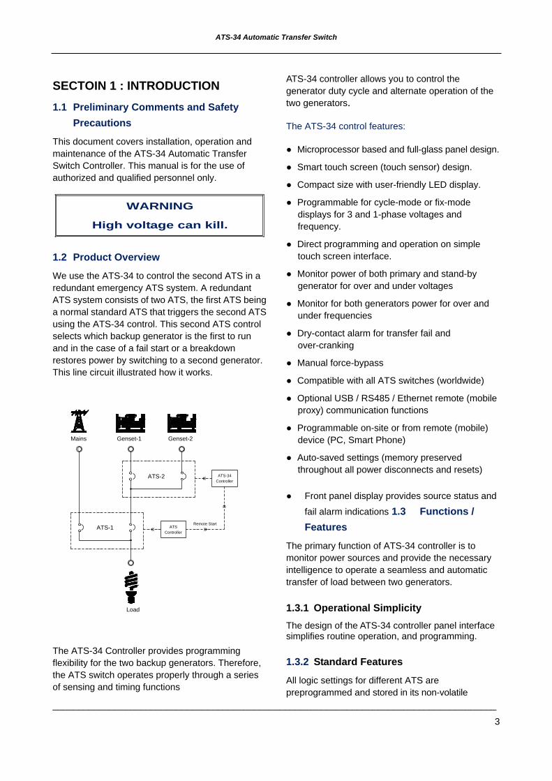
We use the ATS-34 to control the second ATS in a redundant emergency ATS system. A redundant ATS system consists of two ATS, the first ATS being a normal standard ATS that triggers the second ATS using the ATS-34 control. This second ATS control selects which backup generator is the first to run and in the case of a fail start or a breakdown restores power by switching to a second generator. This line circuit illustrated how it works.
The ATS-34 Controller provides programming flexibility for the two backup generators. Therefore, the ATS switch operates properly through a series of sensing and timing functions
ATS-34 controller allows you to control the generator duty cycle and alternate operation of the two generators.
The ATS-34 control features:
● Microprocessor based and full-glass panel design.
● Smart touch screen (touch sensor) design.
● Compact size with user-friendly LED display.
● Programmable for cycle-mode or fix-mode displays for 3 and 1-phase voltages and frequency.
● Direct programming and operation on simple touch screen interface.
● Monitor power of both primary and stand-by generator for over and under voltages
● Monitor for both generators power for over and under frequencies
● Dry-contact alarm for transfer fail and over-cranking
● Manual force-bypass
● Compatible with all ATS switches (worldwide)
● Optional USB / RS485 / Ethernet remote (mobile proxy) communication functions
● Programmable on-site or from remote (mobile) device (PC, Smart Phone)
● Auto-saved settings (memory preserved throughout all power disconnects and resets)
● Front panel display provides source status and
fail alarm indications 1.3 Functions / Features
The primary function of ATS-34 controller is to monitor power sources and provide the necessary intelligence to operate a seamless and automatic transfer of load between two generators.
1.3.1 Operational Simplicity The design of the ATS-34 controller panel interface simplifies routine operation, and programming.
1.3.2 Standard Features
All logic settings for different ATS are preprogrammed and stored in its non-volatile
Genset-1 Genset-2
Load
Mains
ATSController
ControllerATS-34
Remote StartATS-1
ATS-2

ATS-34Automatic Transfer Switch
______________________________________________________________________________________
4
random-access memory (NVRAM), this random-access memory retains its information when power is turned off. Activated feature set points are available for user adjustment.
Feature 1: Generator Duty Time Setting
You can program the ATS-34 for individual operating duty time for each generator. When the working generator times out, the ATS-34 starts the next generator and transfers the switch to that unit. (See lines 3 & 4)
Adjustable Duty Time range: 0 ~ 250 Hours
Feature 2: Transferring Time Delay
The ATS-34 controller provides a time delay when transferring from one generator to the other. Countdown begins when the standby source becomes available. (See line 5)
Adjustable time delay range: 0 ~ 250 sec
Feature 3: Time Delay Engine Cool-down
Controller permits the generator to run unloaded (cool down) after transferring to the other generator. Countdown starts when the transfer is completed. (See line 6)
Adjustable time delay range: 0 ~ 250 sec
Feature 4: Time Delay OFF Position
Time Delay on OFF stops the switch in the center OFF position (completely disconnected) before transferring to the other generator. (See line 7)
Adjustable time delay range: 0 ~ 99 sec
Feature 5: Under / Over voltage Sensing
The controller monitors the output voltage for both generators. You can set the working voltage window on lines 8, 9, 10, 11, 15, & 16
Adjustable Over voltage range: 110VAC ~ 500VAC
Adjustable Under voltage range: 80VAC ~ 470VAC
Feature 6: Under / Over frequency Sensing The controller also monitors the Hertz for each generator. (see line 12, 13, 14, 18, & 19)
Adjustable Over frequency range: 51Hz ~ 75Hz
Adjustable Under frequency range: 40Hz ~ 59Hz
SECTOIN 2: OPERATION PANEL 2.1 General
Familiarize yourself with ATS-34 hardware
● The Front Display Window
● The Touch Buttons and the
● Panel LEDs Display
2.2 Display Window
The ATS-34 controller has a four-digit, seven-segment display panel to monitor all parameters, setting and messages.
Presenting different actions on the display window:
● Dual generators voltage / Duty time / Parameter display
● Time delay countdown display
● Program setting parameter display
2.3 Operate Touch Buttons The front panel supports five sensitive capacitive touch and release buttons,

ATS-34 Automatic Transfer Switch
______________________________________________________________________________________
5
Using the buttons on the control
Icon Description Increase/Selection Touch Button● Press to increase value
● Press to select voltage
AUTO Touch Button● Press to engage AUTO
● Press to reset alarm
OFF Touch Button● Press OFF
● Press to enter program mode
Bypass Touch Button● Press to force a trabsfer
Decrease/Selection Touch Button● Press to decrease value
● Press for Volt / Duty / Freq display
2.3.1 Increase (▲) Button
When the ATS-34 controller is in AUTO, each touch of the up arrow (▲) changes the display to the next phase voltage reading
When in programming mode, each touch of the Increase (▲) key scrolls through all available parameters. When touching and releasing the increase (▲) button, the displayed parameter changes and increases in single units. The Increase (▲) button will continue to scroll when held down
2.3.2 Decrease (▼) Button
Under AUTO operate status, each touch of the decrease (▼) button will change the real parameter display between voltage, duty time and frequency.
When in programming mode, each touch of the decrease (▼) key will scroll through all available parameters. When touching and releasing the decrease (▼) button, the displayed parameter changes and decreased by one value at a time. The decrease (▼) button will continue to scroll if it is
pressed and held down
2.3.3 Auto Key
When selecting the AUTO key, the ATS-34 runs in automatic mode lighting the corresponding LED to indicate the selection. The controller automatically starts the generator, transfer and retransfers from source to source as commanded by the features supplied and the preprogrammed setting.
In AUTO, all anomaly are accompanied by its matching alarm output make sure all failures are corrected before touching the auto key to reset the alarm signal.
WARNING When any failure occurs at its duty time, the controller will shut down the engine, sound an alarm output and switch to the other generator. The failed engine will not start again unless the user manually resets the alarm output by touching the AUTO key.
2.3.4 Bypass Function Button
The Bypass button provides for a manual override of pre-programmed functions. When the ATS-34 is in AUTO, touching the Bypass key ignores the current timers and setting, and the controller will force-start the second generator and transfer the switch from the current working generator to the second generator. The Bypass function can be activated only in AUTO.
LEDs status under Bypass mode

ATS-34Automatic Transfer Switch
______________________________________________________________________________________
6
2.3.5 The OFF Key
Touching the OFF key, turns the ATS-34 OFF engaging a flashing red LED instantly disabling all functions.
However, in program mode, touching the off button allows the user to change to the next program line to set new parameters using the decrease (▼) or increase (▲) button.
2.4 Panel LED Outputs
Eight individual red LEDs and four blue LEDs bars are lit when performing or indicating a specific function.
Information concerning the LEDs output
Power available display for G1 and G2
Generator-1 Over Voltage
Generator-1 Under Voltage
Generator-1 Over Frequency
Generator-1 Under Frequency
Generator-2 Over Voltage
Generator-2 Under Voltage
Generator-2 Over Frequency
Generator-2 Under Frequency
ATS-34 Automatic Transfer Switch
______________________________________________________________________________________
7
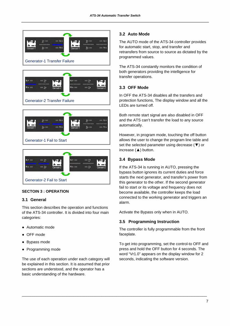
Generator-1 Transfer Failure
Generator-2 Transfer Failure
Generator-1 Fail to Start
Generator-2 Fail to Start
SECTOIN 3 : OPERATION
3.1 General
This section describes the operation and functions of the ATS-34 controller. It is divided into four main categories:
● Automatic mode
● OFF mode
● Bypass mode
● Programming mode
The use of each operation under each category will be explained in this section. It is assumed that prior sections are understood, and the operator has a basic understanding of the hardware.
3.2 Auto Mode
The AUTO mode of the ATS-34 controller provides for automatic start, stop, and transfer and retransfers from source to source as dictated by the programmed values.
The ATS-34 constantly monitors the condition of both generators providing the intelligence for transfer operations.
3.3 OFF Mode
In OFF the ATS-34 disables all the transfers and protection functions, The display window and all the LEDs are turned off.
Both remote start signal are also disabled in OFF and the ATS can’t transfer the load to any source automatically.
However, in program mode, touching the off button allows the user to change the program line table and set the selected parameter using decrease (▼) or increase (▲) button.
3.4 Bypass Mode
If the ATS-34 is running in AUTO, pressing the bypass button ignores its current duties and force starts the next generator, and transfer’s power from this generator to the other. If the second generator fail to start or its voltage and frequency does not become available, the controller keeps the load connected to the working generator and triggers an alarm.
Activate the Bypass only when in AUTO.
3.5 Programming Instruction The controller is fully programmable from the front faceplate.
To get into programming, set the control-to OFF and press and hold the OFF button for 4 seconds. The word “Vr1.0” appears on the display window for 2 seconds, indicating the software version.

ATS-34Automatic Transfer Switch
______________________________________________________________________________________
8
Now you are ready to start the line-by-line programming sequence. Press the OFF key to advance to the next programming line. To change each parameter, press the increase (▲) and decrease (▼) keys. When pressing and releasing the increase (▲) or decrease (▼) key, the displayed parameter can be increased or decreased by one. The Increase (▲) or decrease (▼) will continue to scroll if it is pressed and not released.
Always press the “OFF” button to advance to the next programming line or until the word “End” appears on the screen. To end and exit at any time, simply hold the “OFF” key for 4 seconds.
If you make an error or need to return to factory settings, stay or reenter programming mode and hold the AUTO keys down for 4 seconds, until the word “Au.Po” appears on the display confirming all settings are reset to factory. (See line by line programming table for ATS-34 factory settings.)
3.6 Remote Communication Instruction You can monitor and control the two gen-set on a remote PC using the optional USB / RS485 / Ethernet remote communication modules.
WARNING A remote start signal can activate the ATS-34 and the engines can start at anytime without warning. Place a “Danger” warning sign next
to each generator, STATING THAT THIS GENERATOR CAN START AT ANYTIME!”
also install a warning buzzer or a flash light. Unexpected engine starts can result in
serious injury or death. When performing service or maintenance, always disconnect
the remote start signal input.
A free App enables the customer to remotely monitor and operate the ATS or generators via portable mobile device. Operating software currently available for Apple iOS5.1 system or above and Android operating system. Free software can be downloaded from App Store or Google Play by simply key in “Kutai” and hit search.
KCU-01 – USB communication module
KCU-02 – RS-485 communications module
KCU-03 – Ethernet communications module
The corresponding program settings for ATS-34 installed with KCU-XX module includes item [22], [23] and [24]. Programming item [22] is a must. When Item [22] is set to "00", then the remote monitoring software is restricted to read information only whereas remote command is strictly forbidden.
If KCU-02 - RS485 communication module is installed, additional program setting on lines [23] and [25] are needed.
WARNING ATS-34 with KCU-02 module constitutes a
closed LAN network. Each controller address can be set from 1 to 99 and not to be repeated. Same transmission rate is a must!!
For more detail, information refers to the KCU-XX user manual.
The installation for the KCU-XX communication module on the ATS-34 controller is fairly simple.
Step 1: Remove cover on the back of the ATS-34.
Step 2: Plug in tighten the screw on the KCU-XX module to the ATS-34 PCB.

ATS-34 Automatic Transfer Switch
______________________________________________________________________________________
9
ATS-34Automatic Transfer Switch
______________________________________________________________________________________
10
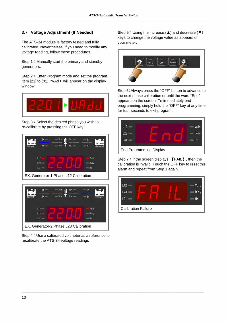
3.7 Voltage Adjustment (If Needed)
The ATS-34 module is factory tested and fully calibrated. Nevertheless, if you need to modify any voltage reading, follow these procedures.
Step 1:Manually start the primary and standby generators.
Step 2:Enter Program mode and set the program item [21] to (01). “VAdJ” will appear on the display window.
Step 3:Select the desired phase you wish to re-calibrate by pressing the OFF key.
EX. Generator-1 Phase L12 Calibration
EX. Generator-2 Phase L23 Calibration
Step 4:Use a calibrated voltmeter as a reference to recalibrate the ATS-34 voltage readings
Step 5:Using the increase (▲) and decrease (▼) keys to change the voltage value as appears on your meter.
Step 6:Always press the “OFF” button to advance to the next phase calibration or until the word “End” appears on the screen. To immediately end programming, simply hold the “OFF” key at any time for four seconds to exit program.
End Programming Display
Step 7:If the screen displays 【FAIL】, then the calibration is invalid. Touch the OFF key to reset this alarm and repeat from Step 1 again.
Calibration Failure

ATS-34 Automatic Transfer Switch
______________________________________________________________________________________
11
3.8 Line by Line Programming Table
ITEM DISCRIPTION VALUE FACTORY SETTING
1 ATS operating in 1 or 3-phase? 00 1Ø 01 3Ø 01
2 Select Switch type of ATS. See drawing on the back of this manual for different switch types
00) MCCB BTS type ATS ( single motor ) 01) Mot type ATS ( dual motors ) 02) Air circuit breaker ( ACB ) 03) Double throw type ( Single coil ) 04) Double throw type ( Dual coils ) 05) Kutai TS-xxx type ATS
00
3 Select the leading generator 00 G1 Priority 01 G2 Priority 02 Alternating Priority 02
4 Flip/flop - Relay Operation duty time 00 ~ 250 Hour ( 00 = No Relay operation) 08Hr
5 Time delay load transfer 00 ~ 250sec 10sec 6 Time delay engine cool-down 00 ~ 250 sec 30sec 7 Time delay ATS in OFF position 00 ~ 99 sec 5sec 8 Generator-1 over voltage setting 11 ~ 50 ( 110V ~ 500V ) 25 (250V) 9 Generator-1 under voltage setting 08 ~ 47 ( 80V ~ 470V ) 18 (180V)
10 Time delay if there is a problem with Generator-1 voltage output
00 ~ 99sec ( 00 = Without voltage monitor function )
10sec
11 Generator-1 over frequency setting 51 ~ 75Hz 65Hz 12 Generator-1 under frequency setting 40 ~ 59Hz 55Hz
13 Time delay if there is a problem with Generator-1 frequency output
00 ~ 99sec ( 00 = Without frequency monitor function )
10sec
14 Generator-2 over voltage setting 11 ~ 50 ( 110V ~ 500V ) 25 (250V) 15 Generator-2 under voltage setting 8 ~ 47 ( 80V ~ 470V ) 18 (180V)
16 Time delay if there is a problem with Generator-2 voltage output
00 ~ 99sec ( 00 = Without volt monitor function )
10sec
17 Generator-2 over frequency setting 51 ~ 75Hz 65Hz 18 Generator-2 under frequency setting 40 ~ 59Hz 55Hz
19 Time delay if there is a problem with Generator-2 frequency output
00 ~ 99sec ( 00 = Without frequency monitor function )
10sec
20 Display mode setting 00 Cyclic mode 01 Fix mode 00 21 Do you want to calibrate voltage reading? 00 NO 01 YES 00
22 Accept remote switch transfer operation (Include emergency stop) 00 NO 01 YES 00
23 KCU-02 module address 00 KCU-02 module restricted 01 ~ 99 00
24 KCU-02 module transmission rate 01 115200 02 57600 03 38400 04 19200 05 14400 06 9600 07 4800 08 2400 09 1200
03

ATS-34Automatic Transfer Switch
______________________________________________________________________________________
12
3.9 Specification Summary
PARAMETER SPECIFICATIONDC Power Supply Voltage 8~60VDC
AC Voltage Measurement Range 50 VAC to 510 VAC 50/60 HZ
Frequency Measurement Range 45HZ to 70HZ
Remote Start Contact 7A @ 250VAC Max
Generator-1 ON Contact 7A @ 250VAC Max
Generator-2 ON Contact 7A @ 250VAC Max
Operating Temperature -20°C ~ 70°C
Storage Temperature -30°C ~ 80°C
Operating Humidity Maximum 90% relative humidity
Weight 495 g ± 2%
SECTION 4: INSTALLATION INSTRUCTIONS
4.1 General
The designed of the ATS-34 controller is for front panel mounting.
4.2 Panel Cut-Out ( All Dimensions in MM. )

ATS-34 Automatic Transfer Switch
______________________________________________________________________________________
13
4.3 Unit Dimensions (mm)
4.4 Installation Reference
ª ¿½ è̈ ¾¤ ô± ø ± ±̈ î¾ ¹¶ }¤ Õ
± ±̈ î³ æ¤ ¸
- ±ª O
© T© w° U¬ [
Á ³µ ·
Á ³µ ·
© T© w° U¬ [

ATS-34 Automatic Transfer Switch
______________________________________________________________________________________
14
SECTION 5: TYPICAL WIRING 5.1 MCCB Type ATS Wiring Diagram (3P/4P)(220VAC)
MC
CB
TYP
E B
TSL2 LO
AD
L1N
L3
Genset-2
L3N L1L2
ATS
-34 Control U
nit
#NLS>>G
enerator-1 Auxiliary Sw
itch#ELS>>G
enerator-2 Auxiliary Sw
itch
Genset-1
L3N L1L2
ATS-34 Automatic Transfer Switch
______________________________________________________________________________________
15
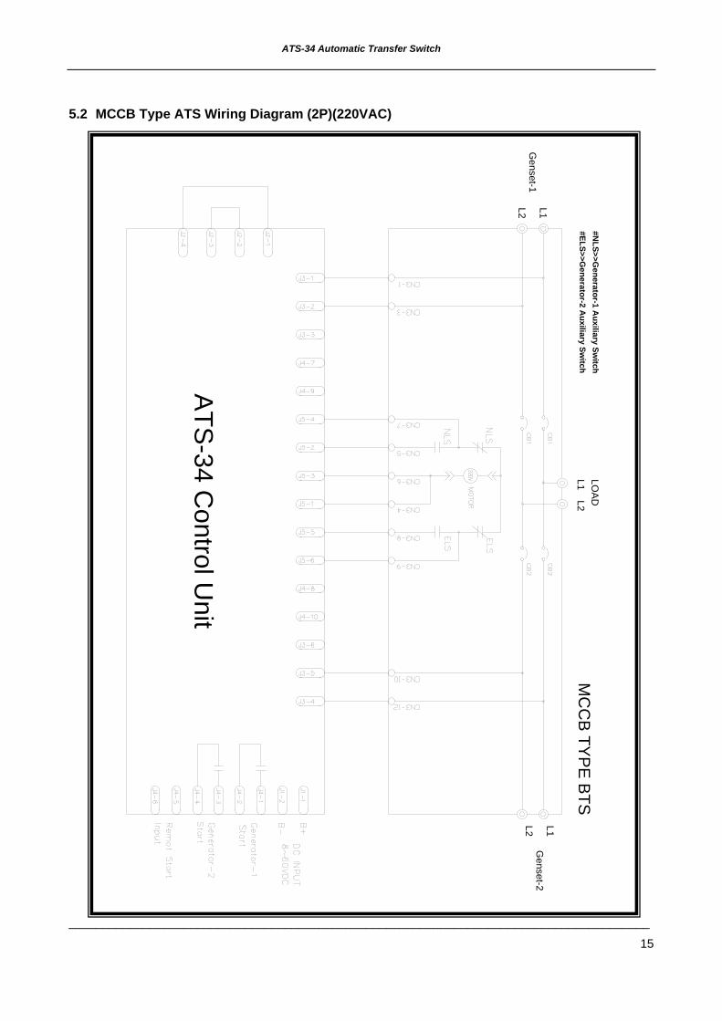
5.2 MCCB Type ATS Wiring Diagram (2P)(220VAC)
#ELS>>Generator-2 A
uxiliary Switch
#NLS>>G
enerator-1 Auxiliary Sw
itch
L2 L1G
enset-2
L1 LOA
DL2M
CC
B TY
PE
BTS
L2 L1G
enset-1
ATS
-34 Control U
nit

ATS-34 Automatic Transfer Switch
______________________________________________________________________________________
16
5.3 MOT Type ATS Wiring Diagram (3P/4P)(220VAC)
ATS
-34 Control U
nit
L2 LOA
D
L1N
L3
Genset-1
Genset-2
N L2L3 L1
A(O
n)
D(P
2)
B(O
ff)
N-M
OTO
R U
NIT
D(P2)
C(P
1)B
(Off)
A(O
n)
L3 L2N L1
E-M
OTO
R U
NITC
(P1)
MO
T TYPE B
TS#N
LS>>Generator-1 A
uxiliary Switch
#ELS>>Generator-2 A
uxiliary Switch

ATS-34 Automatic Transfer Switch
______________________________________________________________________________________
17
5.4 MOT Type ATS Wiring Diagram (2P)(220VAC)
ATS
-34 Control U
nit
#ELS>>Generator-2 A
uxiliary Switch
#NLS>>G
enerator-1 Auxiliary Sw
itchM
OT TY
PE
BTS
C(P
1)
E-M
OTO
R U
NIT
L1L2
A(O
n)B
(Off)
C(P
1)
D(P
2)
N-M
OTO
R U
NIT
B(O
ff)
D(P
2)
A(O
n)
L1L2G
enset-2G
enset-1
L1 LOA
DL2

ATS-34 Automatic Transfer Switch
______________________________________________________________________________________
18
5.5 Air Circuit Breaker Type ATS Wiring Diagram (3P/4P)(220VAC)
ATS
-34 Control U
nit
XF : ON
Coil
MX
1: Trip coil
MC
H: C
harging Alternator
L2 LOA
D
L1N
L3
Genset-2
Genset-1
L2N L3 L1
AC
B TY
PE
BTS
L3N L2 L1

ATS-34 Automatic Transfer Switch
______________________________________________________________________________________
19
5.6 Air Circuit Breaker Type ATS Wiring Diagram (2P)(220VAC)
ATS
-34 Control U
nit
L1L2
AC
B TYP
E BTS
L1L2G
enset-1G
enset-2
L1 LOADL2
MC
H: C
harging Alternator
MX
1: Trip coilX
F : ON
Coil

ATS-34 Automatic Transfer Switch
______________________________________________________________________________________
20
5.7 Single Coil Double Throw Type ATS Wiring Diagram (3P/4P)(220VAC)
#NLS>>G
enerator-1 Auxiliary Sw
itch#ELS>>G
enerator-2 Auxiliary Sw
itch
Genset-2
Genset-1
L3N
L1
LOAD
L2
L2 L1N L3
N L1L3 L2
1 CO
IL DO
UB
LE THR
OW
TYP
E
CS1
CS1
CS1
CS1
CS2
CS2
CS2
CS2
ATS
-34 Control U
nit

ATS-34 Automatic Transfer Switch
______________________________________________________________________________________
21
5.8 Single Coil Double Throw Type ATS Wiring Diagram (2P)(220VAC) #ELS>>G
enerator-2 Auxiliary Sw
itch#N
LS>>Generator-1 A
uxiliary Switch
1 CO
IL DO
UB
LE TH
RO
W TY
PE
L2 L1L1L2
L2
LOAD
L1
Genset-1
Genset-2
CS1
CS1
CS2
CS2
ATS
-34 Control U
nit

ATS-34 Automatic Transfer Switch
______________________________________________________________________________________
22
5.9 Dual Coil Double Throw Type ATS Wiring Diagram (3P/4P)(220VAC)
ATS
-34 Control U
nit
Genset-1
Genset-2
L2 LOA
D
L1N
L3
L3N L1L2
N L1L2L3
2 CO
ILS D
OU
BLE
THR
OW
TYP
E#N
LS>>Generator-1 A
uxiliary Switch
#ELS>>Generator-2 A
uxiliary Switch
CS1
CS1
CS1
CS1
CS2
CS2
CS2
CS2
ATS-34 Automatic Transfer Switch
______________________________________________________________________________________
23
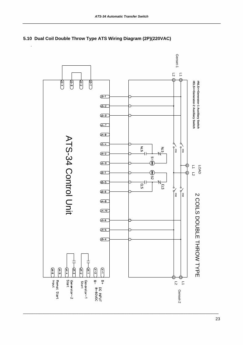
5.10 Dual Coil Double Throw Type ATS Wiring Diagram (2P)(220VAC)
ATS
-34 Control U
nit
#ELS>>Generator-2 A
uxiliary Switch
#NLS>>G
enerator-1 Auxiliary Sw
itch2 C
OILS
DO
UB
LE TH
RO
W TY
PE
L2 L1L2 L1
L1 LOA
DL2
Genset-2
Genset-1
CS1
CS1
CS2
CS2

ATS-34 Automatic Transfer Switch
______________________________________________________________________________________
24
5.11 KUTAI TS-XXX Type ATS Wiring Diagram (3P/4P)(220VAC)
ATS
-34 Control U
nit
L3L1
LOA
D
L2
E2E3 E1
KU
TAI TS3P125
CN1-4
CN1-12
CN1-8
CN1-3
YELLOW
ORANGE
RED/WHITE
GRAY
CS2
CS2
CS2
CS1
CS1
CS1
CN1-2
220VC
OIL
RED
CN1-10
CN1-6
CN1-11
ELS
CN1-9
NLS
BLACK
WHITE
PINK
BLUE
N2
N3
N1
CN1-1BROWN
CN1-5GREEN
#ELS>>Generator-2 A
uxiliary Switch
#NLS>>G
enerator-1 Auxiliary Sw
itch
Genset-1
Genset-2

ATS-34 Automatic Transfer Switch
______________________________________________________________________________________
25
5.12 KUTAI TS-XXX Type ATS Wiring Diagram (2P)(220VAC)
ATS
-34 Control U
nit
#NLS>>G
enerator-1 Auxiliary Sw
itch#ELS>>G
enerator-2 Auxiliary Sw
itch
GREEN CN1-5
BROWN CN1-1
N1
N2
BLUE
PINK
BLACK
NLS
ELS
CN1-11
CN1-6
CN1-10
RED
CO
IL220VCN1-2
CS1
CS1
CS2
CS2
ORANGE CN1-3
KU
TAI TS2P125
E1E2
L2
LOA
D
L1
GRAY
YELLOW
CN1-8
CN1-4
Genset-1
Genset-2

ATS-34 Automatic Transfer Switch
______________________________________________________________________________________
26
5.13 KME WN Type and AICHI WN type ATS Wiring Diagram (3P/4P)(220VAC)
ATS
-34 Control U
nit
Genset-2
Genset-1
L3N
L1
LOA
D
L2
N
KM
E W
N TY
PE B
TSA
ICH
I WN
-TYS
TYP
E B
TS
L2L3 L1
L3N L2 L1
#NLS>>G
enerator-1 Auxiliary Sw
itch#ELS>>G
enerator-2 Auxiliary Sw
itch
CS1
CS1
CS1
CS1
CS2
CS2
CS2
CS2

ATS-34 Automatic Transfer Switch
______________________________________________________________________________________
27
5.14 KME WN Type and AICHI WN type ATS Wiring Diagram (2P)(220VAC)
ATS
-34 Control U
nit AIC
HI W
N-TY
S TY
PE
BTS
KM
E W
N TYP
E B
TS
Genset-1
L1L2
L2LO
AD
L1
Genset-2
L1L2
#NLS>>G
enerator-1 Auxiliary Sw
itch#ELS>>G
enerator-2 Auxiliary Sw
itch
CS1
CS1
CS2
CS2

ATS-34 Automatic Transfer Switch
______________________________________________________________________________________
28
5.15 SOCOMEC ATyS-3S type ATS Wiring Diagram (3P/4P)(220VAC)
ATS
-34 Control U
nit
L2 LOA
D
L1N
L3
Genset-2
Genset-1
N L3 L1L2
L3 L1L2N
SO
CO
ME
C A
TyS-3S
TYP
E B
TS
CS1
CS1
CS1
CS1
CS2
CS2
CS2
CS2

ATS-34 Automatic Transfer Switch
______________________________________________________________________________________
29
5.16 SOCOMEC ATyS-3S type ATS Wiring Diagram (2P)(220VAC)
ATS
-34 Control U
nit
SO
CO
ME
C A
TyS-3S
TYP
E B
TS
L2 L1L2 L1
Genset-1
Genset-2
L1 LOA
DL2
CS1
CS1
CS2
CS2

ATS-34 Automatic Transfer Switch
______________________________________________________________________________________
30
5.17 SOCOMEC ATyS-3e type ATS Wiring Diagram (3P/4P)(220VAC)
ATS
-34 Control U
nit
SO
CO
ME
C A
TyS-3e TY
PE
BTS
L2 LOA
D
L1N
L3
Genset-2
Genset-1
N L2 L1L3
N L1L2L3C
S1
CS1
CS1
2 SC
1SC
CS2
CS2
CS2

ATS-34 Automatic Transfer Switch
______________________________________________________________________________________
31
5.18 SOCOMEC ATyS-3e type ATS Wiring Diagram (2P)(220VAC)
ATS
-34 Control U
nit
L2 L1L1L2
Genset-1
Genset-2
L1 LOA
DL2S
OC
OM
EC
ATyS
-3e TYP
E B
TSC
S1
CS1
CS2
CS2

ATS-34 Automatic Transfer Switch
______________________________________________________________________________________
32
5.19 SOCOMEC ATyS-6 type ATS Wiring Diagram (3P/4P)(220VAC)
ATS
-34 Control U
nit
L2 LOAD
L1N
L3
Genset-2
Genset-1
L1N L3 L2L1L3 L2N
SO
CO
ME
C A
TyS-6 TY
PE
BTS
CS1
CS1
CS1
2SC
1 SC
CS2
CS2
CS2

ATS-34 Automatic Transfer Switch
______________________________________________________________________________________
33
5.20 5.20 SOCOMEC ATyS-6 type ATS Wiring Diagram (2P)(220VAC)
ATS
-34 Control U
nit
L2 LOA
D
L1N
L3
Genset-2
Genset-1
L1L3N L2L1N L2L3
SO
CO
ME
C A
TyS-6e TY
PE
BTS
CS1
CS1
CS1
2SC
1SC
CS2
CS2
CS2

ATS-34 Automatic Transfer Switch
______________________________________________________________________________________
34
5.21 SOCOMEC ATyS-6e type ATS Wiring Diagram (3P/4P)(220VAC)
ATS
-34 Control U
nit
L2 LOA
D
L1N
L3
Genset-2
Genset-1
L1L3N L2L1N L2L3
SO
CO
ME
C A
TyS-6e TY
PE
BTS
CS1
CS1
CS1
2SC
1SC
CS2
CS2
CS2
ATS-34 Automatic Transfer Switch
______________________________________________________________________________________
35
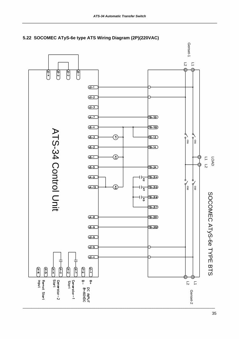
5.22 SOCOMEC ATyS-6e type ATS Wiring Diagram (2P)(220VAC)
ATS
-34 Control U
nit
SO
CO
ME
C A
TyS-6e TY
PE
BTS
L2
LOAD
L1
Genset-2
Genset-1
L1L2L1L2
CS1
CS1
CS2
CS2

ATS-34 Automatic Transfer Switch
______________________________________________________________________________________
36
5.23 MITSUBISHI MD type ATS Wiring Diagram (3P/4P)(220VAC)
ATS
-34 Control U
nit
L2 LOA
D
L1N
L3
Genset-2
Genset-1
L3N L1L2
MITSU
BISH
I MD
TYP
E B
TS
A1
E-M
OTO
R U
NIT
CB
A2
A1
BC
N-M
OTO
R U
NIT
A2
N L1L2L3
#NA
U>>G
enerator-1 Auxiliary Sw
itch#EA
U>>G
enerator-2 Auxiliary Sw
itch

ATS-34 Automatic Transfer Switch
______________________________________________________________________________________
37
5.24 MITSUBISHI MD type ATS Wiring Diagram (2P)(220VAC)
ATS
-34 Control U
nit
#EAU
>>Generator-2 A
uxiliary Switch
#NA
U>>G
enerator-1 Auxiliary Sw
itch
L2 L1
A2 N-M
OTO
R U
NIT
CB
A1
A2
BC
E-M
OTO
R U
NIT
A1
MITS
UB
ISHI M
D TY
PE
BTS
L2 L1G
enset-1G
enset-2
L1 LOADL2

ATS-34 Automatic Transfer Switch
______________________________________________________________________________________
38
5.25 MERLIN GERIN MCB type ATS Wiring Diagram (3P/4P)(220VAC)
ATS
-34 Control U
nit
L2 LOAD
L1N
L3
Genset-2
Genset-1
N L3 L2 L1
MC
H: C
harging Alternator
MG
MC
B TY
PE
BTS
XF : O
N C
oilM
X1: Trip coil
L2L3N L1

ATS-34 Automatic Transfer Switch
______________________________________________________________________________________
39
5.26 MERLIN GERIN MCB type ATS Wiring Diagram (2P)(220VAC)
ATS
-34 Control U
nit
L1L2
MX
1: Trip coilX
F : ON
Coil
MG
MC
B TY
PE
BTS
MC
H: C
harging Alternator
L1L2G
enset-1G
enset-2
L1 LOADL2
ATS-34 Automatic Transfer Switch
______________________________________________________________________________________
40
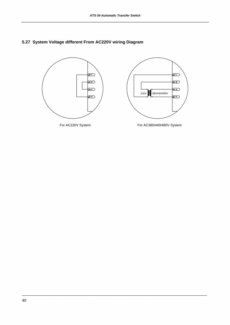
5.27 System Voltage different From AC220V wiring Diagram
For AC380/440/480V SystemFor AC220V System
220V 380/440/480V