Embed Size (px)
Citation preview
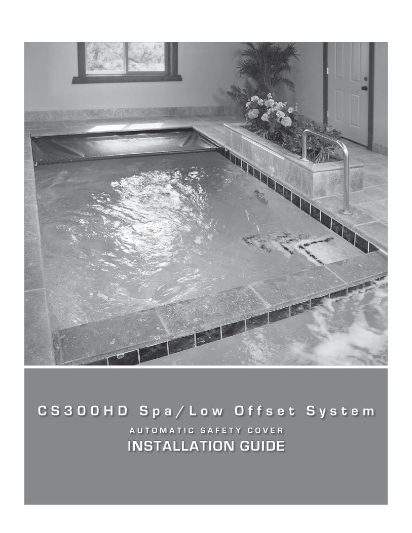
C S 3 0 0 H D S p a / L o w O f f s e t S y s t e mA U T O M A T I C S A F E T Y C O V E R
INSTALLATION GUIDE
Automatic Safety SpaCover
2
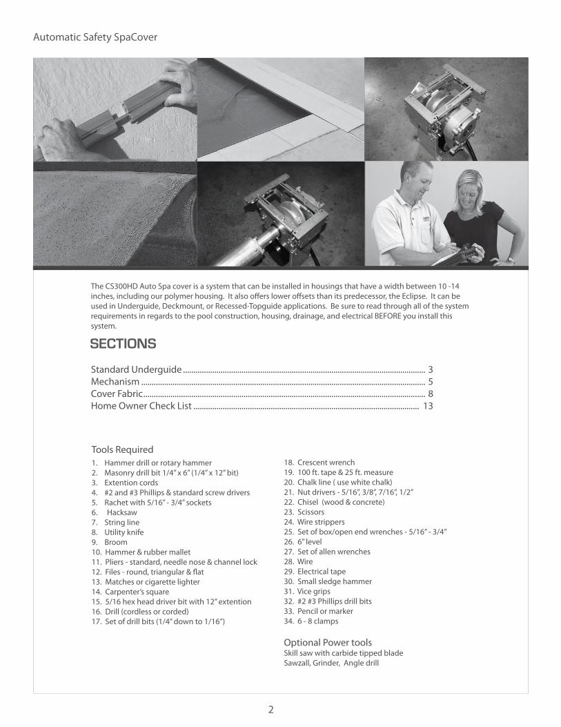
The CS300HD Auto Spa cover is a system that can be installed in housings that have a width between 10 -14 inches, including our polymer housing. It also offers lower offsets than its predecessor, the Eclipse. It can be used in Underguide, Deckmount, or Recessed-Topguide applications. Be sure to read through all of the system requirements in regards to the pool construction, housing, drainage, and electrical BEFORE you install this system.
SECTIONS
Standard Underguide .................................................................................................................... 3Mechanism ........................................................................................................................................ 5Cover Fabric ....................................................................................................................................... 8Home Owner Check List ............................................................................................................ 13
Tools Required1. Hammer drill or rotary hammer2. Masonry drill bit 1/4” x 6” (1/4” x 12” bit)3. Extention cords4. #2 and #3 Phillips & standard screw drivers5. Rachet with 5/16” - 3/4” sockets6. Hacksaw7. String line8. Utility knife9. Broom10. Hammer & rubber mallet11. Pliers - standard, needle nose & channel lock12. Files - round, triangular & flat13. Matches or cigarette lighter14. Carpenter’s square15. 5/16 hex head driver bit with 12” extention16. Drill (cordless or corded)17. Set of drill bits (1/4” down to 1/16”)
18. Crescent wrench19. 100 ft. tape & 25 ft. measure20. Chalk line ( use white chalk)21. Nut drivers - 5/16”, 3/8”, 7/16”, 1/2”22. Chisel (wood & concrete)23. Scissors24. Wire strippers25. Set of box/open end wrenches - 5/16” - 3/4”26. 6” level27. Set of allen wrenches28. Wire29. Electrical tape30. Small sledge hammer31. Vice grips32. #2 #3 Phillips drill bits33. Pencil or marker34. 6 - 8 clamps
Optional Power toolsSkill saw with carbide tipped bladeSawzall, Grinder, Angle drill

Installation Guide
3
STANDARD UNDERGUIDE
Step By Step Instructions Page/Step
Mounting the guides Standard Underguide mounting ...................4/6 Encapsulated Underguide mounting ..........4/7
4
Numbers in parenthesis refer to hardware shown on page 19.Step By Step Instructions
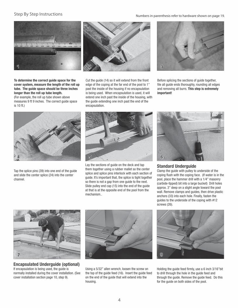
To determine the correct guide space for the cover system, measure the length of the roll up tube. The guide space should be three inches longer than the roll up tube length. (For example, the roll up tube shown above measures 9 ft 9 inches. The correct guide space is 10 ft.)
Cut the guide (14) so it will extend from the front edge of the coping at the far end of the pool to 1” past the inside of the housing if no encapsulation is being used. When encapsulation is used, it will extend one inch past the inside of the housing, with the guide extending one inch past the end of the encapsulation.
Before splicing the sections of guide together, file all guide ends thoroughly, rounding all edges and removing all burrs. This step is extremely important!
Tap the splice pins (39) into one end of the guide and slide the center splice (24) into the center channel.
Lay the sections of guide on the deck and tap them together using a rubber mallet so the center splice and splice pins interlock with each section of guide. It’s important that, the splice is tight together so there is not a gap from one guide to the next. Slide pulley end cap (15) into the end of the guide at that is at the opposite end of the pool from the mechanism..
Using a 5/32” allen wrench, loosen the screw on the top of the guide feed (16). Insert the guide feed on the end of the guide that will extend into the housing.
1 2 3
4 5
8
Standard Underguide Clamp the guide with pulley to underside of the coping flush with the coping face. (If water is in the pool, place the hammer drill with a 1/4” masonry (carbide-tipped) bit into a large bucket) Drill holes approx. 3” deep on a slight angle toward the pool wall. Remove clamps and guides, then drive plastic anchors (33) into each hole. Finally, fasten the guides to the underside of the coping with #12 screws (26).
Encapsulated Underguide (optional)If encapsulation is being used, the guide is normally installed during the cover installation. (See cover installation section page 10, step 9).
6
7
Holding the guide feed firmly, use a 6 inch 3/16”bit to drill through the hole in the guide feed and through the guide. Remove the guide feed. Do this for the guide on both sides of the pool.
9
Installation Guide
5
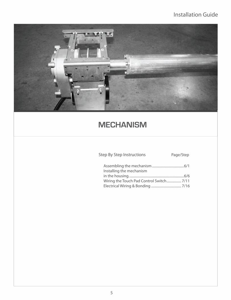
MECHANISM
Step By Step Instructions Page/Step
Assembling the mechanism .....................................6/1 Installing the mechanism in the housing. ...............................................................6/6 Wiring the Touch Pad Control Switch ................. 7/11 Electrical Wiring & Bonding ................................... 7/16

6
Step By Step Instructions Numbers in parenthesis refer to hardware shown on page 19.
Assembling the mechanism.Turn the motor and non-motor end upside down. This is done to appropriately attach the roll up tube and the mechanism mounting feet.
Attach the roll up tube to the non motor end of the mechansim using the 3/8” x 1 1/4” bolts (36) and lock washers (37) provided.
To attach the feet, first measure the distance from the bottom of the housing to the top of the track/encapsulation. (This will determine the height of the mechanism.)
Attach the mechanism feet to the mechanism approximately 1 inch less than the distance from the bottom of the housing to the top of the track/encapsulation. Use a 7/16 inch ratchet to tighten bolts. Tip: The roll up tube should be set as high as possible without allowing the cover rub on the lid brackets.
Installing the mechanism in the housing.Line up the mechanism with the track so the rope will come straight out and around the motor end the pulley. Tip: To help determine this, the water side bracket should measure 1 inch away from the outside of the track.
Center the tube in the housing. Tip: If the pool is not square, square up the mechanism with the track.
Attach the mechanism feet to the floor of the housing. Use the mounting hardware provided.
1 2 3
4 5 6
7 8 9
Raise the pulley brackets and the water side brackets level with the top of the encapsulation. Tighten the bolts for the brackets.
Attach the roll up tube to the motor end of the mechansim using the 3/8” x 1 1/4” bolts (36) and lock washers (37) provided.

7
Installation Guide
Continue connecting the power and directional wires to the pigtails on the controller using wire nuts.
13
Connect the ground wires from the power supply, the motor and the ground wire from the touch pad together using a wire nut.
12
Wiring the Touch Pad Control SwitchThe touch pad control switch will come with pigtails already inserted into the wire connecctions on the back of the touch pad. Note: Switch must be mounted in a position with a full view of the pool.
11
Attach the pulley brackets and water side brackets to the walls of the housing. Use the mounting hardware provided.Secure the cross braces together using the screws (27) and nylock nuts (29) provided.
10
16 Electrical Wiring & BondingThe system must be bonded to meet the National Electrical Code. Bond both guides to the mechanism by attaching a bonding lug to the guidefeed screw and running a #8 solid copper bond wire to the mechanism. Bond the lid to the mechanism by drilling a hole in the lid at either end of the lid and attaching a bonding lug in each position and bonding it to the mechanism. All brackets and any other metal over 4” long should likewise be bonded to the mechanism. There should be a bond wire from the equipment pad inside the housing. Attach this bond wire to the mechanism to complete the bonding requirement. Note: Builder is responsible to bring proper electrical lines, conduit and bonding to the mechanism. Electrical wiring diagram and details are shown above with instructions on the right.
Connect the touch pad by wiring the neutral wire from the power supply, the white wire from the motor and the neutral wire that is connected to the touch pad using a wire nut.
11
After wiring the control switch, if the cover is moving in the opposite direction than the button that is pressed, undo the wire nuts to the directional wires and reverse them.

Automatic Safety SpaCover
8
COVER FABRIC
Step by Step Instructions Page/Step
Installing the cover.......................................................9/1 Running the rope through the mechanism ........9/8 Attaching the guide feed. .....................................11/19 Guide Retainer Method .........................................11/23 Attaching the Ropes to the Rope Reel ............12/28 Pinning the cover to the roll-up tube. ..............12/30 Using the switch and operating the cover to open .....................................................12/33
9
Step By Step Instructions Installation Guide
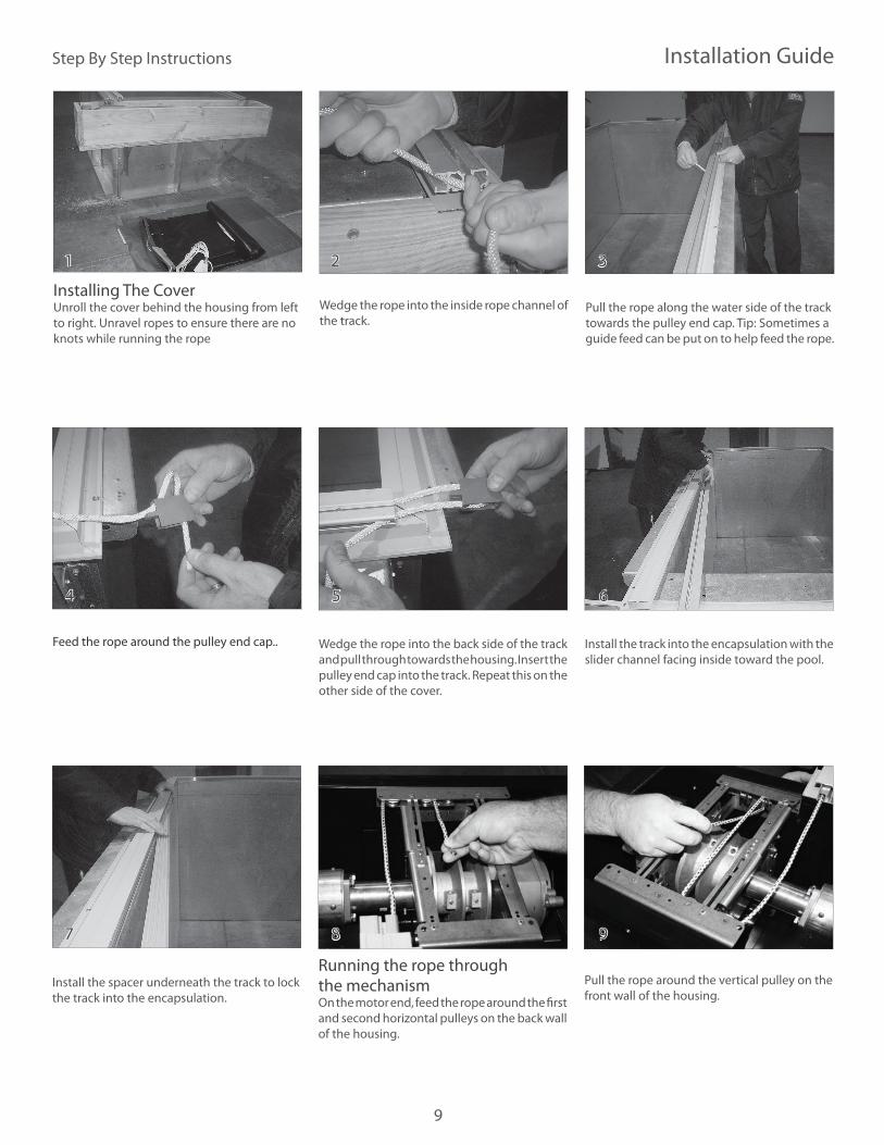
Installing The CoverUnroll the cover behind the housing from left to right. Unravel ropes to ensure there are no knots while running the rope
Wedge the rope into the inside rope channel of the track.
Pull the rope along the water side of the track towards the pulley end cap. Tip: Sometimes a guide feed can be put on to help feed the rope.
Feed the rope around the pulley end cap.. Wedge the rope into the back side of the track and pull through towards the housing. Insert the pulley end cap into the track. Repeat this on the other side of the cover.
Install the track into the encapsulation with the slider channel facing inside toward the pool.
Install the spacer underneath the track to lock the track into the encapsulation.
Running the rope through the mechanismOn the motor end, feed the rope around the first and second horizontal pulleys on the back wall of the housing.
Pull the rope around the vertical pulley on the front wall of the housing.
1 2 3
4 5 6
7 8 9

10
Step By Step Instructions Numbers in parenthesis refer to hardware shown on page 19.
On the non-motor end, feed the rope around the pulley of the non-motor end pulley bracket. Pull the rope through to the motor end.
Note: The cross brace for the non motor end is positioned close to the pulley to add support. It is normal for this to be on a slight angle.
Feed the non-motor end rope behind the first and second and third horizontal pulleys.
Pull the rope around the vertical pulley on the front wall of the housing.
Feed one side of the cover and slider into the track.
Pull the cover into the track so the leading edge loop is over the water.
Insert the leading edge tube into the loop of the cover. Install the other side of the cover and slider.
10 11 12
13 14 15
12
5 4
Insert the leading edge inserts into the leading edge tube.
Attach the leading edge insert to the slider by inserting the a screw (41) from the bottom of the slider. The screw will go through a punched hole in the cover, then into the leading edge insert. Secure using a 10-32 Nylock Nut. (29)
16 17
Install the black cap (10) over the top of the leading edge support bracket. Secure it in place by tightening the screws on the back side of the cap.
18

11
Step By Step Instructions Installation Guide
Pull the cover all the way open until the sliders stop against the guide feeds.
25
Attaching the guide feedUsing an allen wrench, loosen the allen bolt on the guide feed. Turn the top of the guide feed halfway to open. Install the guide feed around the rope and the webbing.
Turn guide feed back to closed over the rope and webbing then tighten the allen bolt.
Slide the guide feed onto the track with the flange inserted in the slider channel.
Drill a hole through the guide feed into the track for the attachment bolt.
19 20 21
22
Guide Retainer MethodWhen using encapsulation on the pool, extend it one inch into the cover housing. When cutting the cover guide to length, extend it one inch past the encapsulation.
Drill through the center of the encapsulation and guide. Insert a 10-32 x 1 3/4 screw (42) and nylock nut (29). This step is very important. This will prevent the guide from sliding into the cover housing duirng the operation of the cover system.
(If the encapsulaiton was cut flush to the inside of the housing, secure the track using a guide retainer bracket (23)).
31
Attach the bonding wire to the leading edge bar using a self tapping screw (32).
Leaving an extra 6-8 feet of extra rope length, pull on the ropes until the leading edge begins to move forward equally on both sides. Burn or wrap the rope with tape and cut to length.
26 27
23 24
12
Step By Step Instructions Numbers in parenthesis refer to hardware shown on page 19.
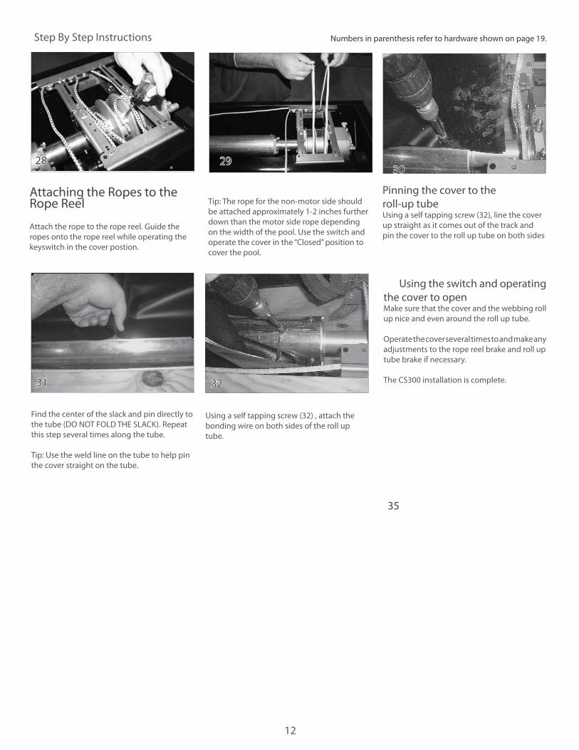
Attaching the Ropes to the Rope Reel
Attach the rope to the rope reel. Guide the ropes onto the rope reel while operating the keyswitch in the cover postion.
Tip: The rope for the non-motor side should be attached approximately 1-2 inches further down than the motor side rope depending on the width of the pool. Use the switch and operate the cover in the “Closed” position to cover the pool.
Pinning the cover to the roll-up tubeUsing a self tapping screw (32), line the cover up straight as it comes out of the track and pin the cover to the roll up tube on both sides
Find the center of the slack and pin directly to the tube (DO NOT FOLD THE SLACK). Repeat this step several times along the tube.
Tip: Use the weld line on the tube to help pin the cover straight on the tube.
Using a self tapping screw (32) , attach the bonding wire on both sides of the roll up tube.
Using the switch and operating the cover to open Make sure that the cover and the webbing roll up nice and even around the roll up tube.
Operate the cover several times to and make any adjustments to the rope reel brake and roll up tube brake if necessary.
The CS300 installation is complete.
30
31 32
35
32
28 29
Installation Guide
13
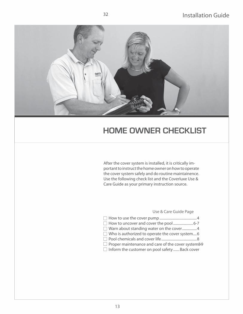
HOME OWNER CHECKLIST
After the cover system is installed, it is critically im-portant to instruct the home owner on how to operate the cover system safely and do routine maintainence. Use the following check list and the Coverluxe Use & Care Guide as your primary instruction source.
Use & Care Guide Page
How to use the cover pump .........................................4 How to uncover and cover the pool ......................6-7 Warn about standing water on the cover ................4 Who is authorized to operate the cover system ....6 Pool chemicals and cover life .......................................8 Proper maintenance and care of the cover system 8-9 Inform the customer on pool safety .......Back cover
32

14
Installation Checklist
GuidesqDoes the guide space measurement match how the cover system was ordered? qAll guide ends filed. This is extremely important qCover goes through the guide joints smoothly.qAll guide screws are tight and flush. qPulleys are flush against the end of the guide.qThe guidefeeds are snug against the guide qGuidefeeds bolted in and are tight.qStops installed.qAlignment pins and splices used when joining the guides, even in encapsulation.
MechanismqMechanism installed level in the box.qTube level in housing.qTube centered between the guides.qEnough clearance top, bottom, sides for the fabric. No rubbing of webbing on sides or bottom of box.qTube at the right height? The ideal location is to install the cover in the box so that the cover is coming off at as small an angle
as possible. This reduces stress on the mechanism and reduces wear on cover guides at the end of the track.qTube either centered in the box or positioned slightly more towards the back of the box, so that the cover is unlikely to rub on
the front of the box. qSystem mounted at right angle to the track.qRopes coming back straight out of the track. An excessive angle will cause wear on the cover guides at the end of the track.qRopes are not rubbing on any brackets or the deck.qRopes are run correctly (see page 15, steps 11-18). q8 feet of rope left on rope reel.qSystem bonded according to electrical code. Cover bonded to leading edge and roll-up tube.qTorque limiter adjusted for the pool (see page 18, steps 37-40). If mechanism is hydraulic, are both bypass valves set slightly
higher than necessary to run the cover?qRope loops installed on each lid bracket so rope cannot droop and snag on cover or lid brackets (see page 20, step 3)qMake sure the system is electrically bonded to meet the National Electrical Code.qMake sure there is adequate drainage from the housing.
CoverqFabric pinned to the take-up tube without pinned folds.qCover is bolted to the wheel assembly.qCover runs smoothly.qCover properly aligned when it closes or retracts. Note: An inch or two out of square is not uncommon and is not a concern as
it will not effect the operation of the cover. Because of the size of the fabric roll, and changes in operating conditions the cover may vary slightly in alignment as it is run.
qThe leading edge inserts move in and out freely the whole length of the pool.qFabric is pinned to the leading edge flush with the ends of the tube.qCover not rubbing in the housing as it rolls up.
Cover LidqAll sharp edges have been filedqAll areas where the lid is not flat on the deck been screwed down to eliminate any potential hazardsqThere is enough clearance between the lid brackets and the cover to avoid rubbing
Misc.qKey switch is in full view of the poolqCover pump tested by putting it in the water and operate it in front of homeownerqThe cover box is clean and clear of debris so that the drains are not easily cloggedqPool area cleaned upqHomeowner has been instructed (see page 21)

15
Installation GuideParts Reference
Mechanism Components
1
Misc. Hardware
Cover Fabric
Cover Lid Lid Support Bracket Cover Pump
2
17
22
20
9
6
8
5
Cover Guide
12
8
7
4 4
13
18 17 19
20
3
Topview
Sideview
3
15
14
21
16
1. E1058 CS300HD Tuck Under Motor2. A2341 Mechanism RT or UG (Right) A2331/ Mechanism RT or UG (Left)3. M8433 Mechanism Mounting Foot 4. M0311 Tube insert for 4” tube5. X0015 4’ aluminum roll-up tube6. A2349 Non-motor end assembly RT/UG (Right) A2339 Non-motor end assembly RT/UG (Left)7. A2469 Standard Touch Pad Control Switch8. A1100 Slider Assembly UG 403 & 801 for detachable ropes9. A0057 Leading edge insert assembly for 1” Flat LE10. M0012 Plastic End Cap for 1 inch flat LE11. X0717 1” Flat Aluminum leading edge12. Cover Cover fabric13. Rope .250 diameter (Length varies)14. A0614 403 underguide, 21’15. A0958 Pulley endcap assembly 403 & 801 UG16. A1884 Guide feed 2 piece SS UG17. X0004 Main Lid18. X0121 Motor End lid19. X0659 Non-motor end lid20. X0943 8” Lid hinge21. A1692 Standard cover lid bracket (set of 2)22. A0338 Little Giant cover pump & instructions
23. A0407 Underguide retainer bracket set
24. M0104 Guide splice UG 40325. E1086 Bonding lug ka-6u (for 1 wire)26. H0332 Screw PPSM 12 x 1-3/4 for UG STD (screw on guide)27. H0150 Parts kit cross brace joining screw28. H0152 Screw PPMS 10-32 x 1/229. H0176 Nut nylock 10-3230. H0075 Rope loop (black plastic)31. H0310 Screw PPSM 10 x 1/232. H0313 Screw HHWSM tek 10 x 1/2 SS33. H0324 Plastic anchor STD #1234. H0331 Screw HHWSM 12 x 1-1/2 w/slot35. H0294 Carriage bolt 1/4-20 x 3/436. H0096 Bolt HH 3/8-16 - 1-1/437. H0006 Split lock washer 3/838. E1098 Bonding wire39. H9630 Spring pin for guide alignment40. H0276 Nut Nylock 1/4-2041. H0130 Screw PFMS 10-32 x 142. H1099 Screw PPMS 10-32 1 3/443. X0651 Encapsulation 403 Gunite 21 ft.44. X0092 Spacer for Gunite encapsulation flange covers encapsulation to tile edge45. X0650 Encapsulation 403 vinyl liner 21 ft46. X0091 Spacer for encapsulated guide 801, 403 light grey 21 ft long ea.
The parts list at above is typical for most pools up to 20’ x 40’ and includes all parts neccesary to install the Coverluxe system,
however, parts will vary for longer or wider pools and according to your specific order.
911
27
37
30 31
34
28
33
36
26
29
32
35
38 39
24 2523
40
41 42 43
44 45 46
Parts List
10 10
© 2010 Coverstar Date: Jan. 2014 Ver: 1.1
L9947
Manufactured by COVERSTAR 1795 West 200 North Lindon,
UT 84042
QUESTIONS?
For questions about this installation guide, contact your independent distributor.