Embed Size (px)
Citation preview

Automatic milking systemMonobox
International Sample unit
Operation Manual / Installation Instructions / Parts List
(Original operating instructions)
7821-9001-005
01 July 2017
gea.com

7821-9001-00501 July 20172 / 98
Contents
1 Vorwort 12. . . . . . . . . . . . . . . . . . . . . . . . . . . . . . . . . . . . . . . . . . . . . . . . . . . . . . . . . . . . . . . . .
1.1 Informationen zur Anleitung 12. . . . . . . . . . . . . . . . . . . . . . . . . . . . . . . . . . . . . . . . . . . . . . . . . . . . . . . . . . . . . . . .
1.2 Herstelleranschrift 13. . . . . . . . . . . . . . . . . . . . . . . . . . . . . . . . . . . . . . . . . . . . . . . . . . . . . . . . . . . . . . . . . . . . . . . . .
1.3 Kundendienst 13. . . . . . . . . . . . . . . . . . . . . . . . . . . . . . . . . . . . . . . . . . . . . . . . . . . . . . . . . . . . . . . . . . . . . . . . . . . .
1.4 Konformitätserklärung 15. . . . . . . . . . . . . . . . . . . . . . . . . . . . . . . . . . . . . . . . . . . . . . . . . . . . . . . . . . . . . . . . . . . . .
1.5 Einbauerklärung 17. . . . . . . . . . . . . . . . . . . . . . . . . . . . . . . . . . . . . . . . . . . . . . . . . . . . . . . . . . . . . . . . . . . . . . . . . .
1.6 Erfolgreiches Melken 19. . . . . . . . . . . . . . . . . . . . . . . . . . . . . . . . . . . . . . . . . . . . . . . . . . . . . . . . . . . . . . . . . . . . . .
2 Sicherheit 21. . . . . . . . . . . . . . . . . . . . . . . . . . . . . . . . . . . . . . . . . . . . . . . . . . . . . . . . . . . . . . .
2.1 Sorgfaltspflicht des Betreibers 21. . . . . . . . . . . . . . . . . . . . . . . . . . . . . . . . . . . . . . . . . . . . . . . . . . . . . . . . . . . . . .
2.2 Erklärung der verwendeten Sicherheitssymbole 23. . . . . . . . . . . . . . . . . . . . . . . . . . . . . . . . . . . . . . . . . . . . . . .
2.3 Grundlegende Sicherheitshinweise 24. . . . . . . . . . . . . . . . . . . . . . . . . . . . . . . . . . . . . . . . . . . . . . . . . . . . . . . . . .
2.4 Personalqualifikation 25. . . . . . . . . . . . . . . . . . . . . . . . . . . . . . . . . . . . . . . . . . . . . . . . . . . . . . . . . . . . . . . . . . . . . .
2.5 Schutzeinrichtungen 26. . . . . . . . . . . . . . . . . . . . . . . . . . . . . . . . . . . . . . . . . . . . . . . . . . . . . . . . . . . . . . . . . . . . . . .
3 Beschreibung 27. . . . . . . . . . . . . . . . . . . . . . . . . . . . . . . . . . . . . . . . . . . . . . . . . . . . . . . . . . .3.1 Bestimmungsgemäße Verwendung 27. . . . . . . . . . . . . . . . . . . . . . . . . . . . . . . . . . . . . . . . . . . . . . . . . . . . . . . . . .
3.2 Veränderungen am Produkt 28. . . . . . . . . . . . . . . . . . . . . . . . . . . . . . . . . . . . . . . . . . . . . . . . . . . . . . . . . . . . . . . .
3.3 Aufbau des Produkts 28. . . . . . . . . . . . . . . . . . . . . . . . . . . . . . . . . . . . . . . . . . . . . . . . . . . . . . . . . . . . . . . . . . . . . .
3.4 Funktionsbeschreibung 28. . . . . . . . . . . . . . . . . . . . . . . . . . . . . . . . . . . . . . . . . . . . . . . . . . . . . . . . . . . . . . . . . . . .
3.5 Technische Daten 29. . . . . . . . . . . . . . . . . . . . . . . . . . . . . . . . . . . . . . . . . . . . . . . . . . . . . . . . . . . . . . . . . . . . . . . .
3.6 Werkseinstellung 30. . . . . . . . . . . . . . . . . . . . . . . . . . . . . . . . . . . . . . . . . . . . . . . . . . . . . . . . . . . . . . . . . . . . . . . . .
4 Transport 31. . . . . . . . . . . . . . . . . . . . . . . . . . . . . . . . . . . . . . . . . . . . . . . . . . . . . . . . . . . . . . .4.1 Besondere Personalqualifikation für den Transport 31. . . . . . . . . . . . . . . . . . . . . . . . . . . . . . . . . . . . . . . . . . . . .
4.2 Sicherheitshinweise für den Transport 31. . . . . . . . . . . . . . . . . . . . . . . . . . . . . . . . . . . . . . . . . . . . . . . . . . . . . . .
4.3 Abmessungen und Gewicht 31. . . . . . . . . . . . . . . . . . . . . . . . . . . . . . . . . . . . . . . . . . . . . . . . . . . . . . . . . . . . . . . .
4.4 Zulässige Vorrichtungen und Hilfsmittel für den Transport 33. . . . . . . . . . . . . . . . . . . . . . . . . . . . . . . . . . . . . . .
4.5 Transport 33. . . . . . . . . . . . . . . . . . . . . . . . . . . . . . . . . . . . . . . . . . . . . . . . . . . . . . . . . . . . . . . . . . . . . . . . . . . . . . . .
4.6 Lieferumfang 34. . . . . . . . . . . . . . . . . . . . . . . . . . . . . . . . . . . . . . . . . . . . . . . . . . . . . . . . . . . . . . . . . . . . . . . . . . . . .
4.7 Lagerbedingungen 35. . . . . . . . . . . . . . . . . . . . . . . . . . . . . . . . . . . . . . . . . . . . . . . . . . . . . . . . . . . . . . . . . . . . . . . .
4.8 Hinweise zur Entsorgung von Verpackungsmaterial 35. . . . . . . . . . . . . . . . . . . . . . . . . . . . . . . . . . . . . . . . . . . .
5 Montage 36. . . . . . . . . . . . . . . . . . . . . . . . . . . . . . . . . . . . . . . . . . . . . . . . . . . . . . . . . . . . . . . .5.1 Besondere Personalqualifikation für die Montage 36. . . . . . . . . . . . . . . . . . . . . . . . . . . . . . . . . . . . . . . . . . . . . .
5.2 Sicherheitshinweise für die Montage 36. . . . . . . . . . . . . . . . . . . . . . . . . . . . . . . . . . . . . . . . . . . . . . . . . . . . . . . . .
5.3 Montagevorbereitungen 38. . . . . . . . . . . . . . . . . . . . . . . . . . . . . . . . . . . . . . . . . . . . . . . . . . . . . . . . . . . . . . . . . . . .
5.4 Umgebungsvoraussetzungen für die Aufstellung 39. . . . . . . . . . . . . . . . . . . . . . . . . . . . . . . . . . . . . . . . . . . . . .
5.5 Transportsicherungen entfernen 39. . . . . . . . . . . . . . . . . . . . . . . . . . . . . . . . . . . . . . . . . . . . . . . . . . . . . . . . . . . .
5.6 Montage von . . . 40. . . . . . . . . . . . . . . . . . . . . . . . . . . . . . . . . . . . . . . . . . . . . . . . . . . . . . . . . . . . . . . . . . . . . . . . . .
5.7 Warnschilder und Warnaufkleber anbringen 41. . . . . . . . . . . . . . . . . . . . . . . . . . . . . . . . . . . . . . . . . . . . . . . . . .
5.8 Entsorgung von Montagematerial nach Abschluss der Montage 41. . . . . . . . . . . . . . . . . . . . . . . . . . . . . . . . .
6 Erste Inbetriebnahme 42. . . . . . . . . . . . . . . . . . . . . . . . . . . . . . . . . . . . . . . . . . . . . . . . . . . .6.1 Besondere Personalqualifikation für die erste Inbetriebnahme 42. . . . . . . . . . . . . . . . . . . . . . . . . . . . . . . . . . .
6.2 Sicherheitshinweise für die erste Inbetriebnahme 42. . . . . . . . . . . . . . . . . . . . . . . . . . . . . . . . . . . . . . . . . . . . . .
6.3 Grundlegende Einstellungen vornehmen 43. . . . . . . . . . . . . . . . . . . . . . . . . . . . . . . . . . . . . . . . . . . . . . . . . . . . .
6.4 Kontrollen vor dem ersten Start 43. . . . . . . . . . . . . . . . . . . . . . . . . . . . . . . . . . . . . . . . . . . . . . . . . . . . . . . . . . . . .
6.5 Erster Start 44. . . . . . . . . . . . . . . . . . . . . . . . . . . . . . . . . . . . . . . . . . . . . . . . . . . . . . . . . . . . . . . . . . . . . . . . . . . . . . .
6.6 Kontrollen nach dem ersten Start 44. . . . . . . . . . . . . . . . . . . . . . . . . . . . . . . . . . . . . . . . . . . . . . . . . . . . . . . . . . . .
6.7 Übergabe an den Betreiber 45. . . . . . . . . . . . . . . . . . . . . . . . . . . . . . . . . . . . . . . . . . . . . . . . . . . . . . . . . . . . . . . . .
7 Bedienung 46. . . . . . . . . . . . . . . . . . . . . . . . . . . . . . . . . . . . . . . . . . . . . . . . . . . . . . . . . . . . . .7.1 Besondere Personalqualifikation für die Bedienung 46. . . . . . . . . . . . . . . . . . . . . . . . . . . . . . . . . . . . . . . . . . . .
7.2 Sicherheitshinweise für die Bedienung 46. . . . . . . . . . . . . . . . . . . . . . . . . . . . . . . . . . . . . . . . . . . . . . . . . . . . . . .
7.3 Arbeitsplätze des Bedienpersonals 48. . . . . . . . . . . . . . . . . . . . . . . . . . . . . . . . . . . . . . . . . . . . . . . . . . . . . . . . . .
7.4 Beschreibung der Bedienelemente 48. . . . . . . . . . . . . . . . . . . . . . . . . . . . . . . . . . . . . . . . . . . . . . . . . . . . . . . . . .
7.5 Bedienen 48. . . . . . . . . . . . . . . . . . . . . . . . . . . . . . . . . . . . . . . . . . . . . . . . . . . . . . . . . . . . . . . . . . . . . . . . . . . . . . . .

7821-9001-00501 July 2017
3 / 98
8 Funktionsstörungen 49. . . . . . . . . . . . . . . . . . . . . . . . . . . . . . . . . . . . . . . . . . . . . . . . . . . . .
8.1 Besondere Personalqualifikation für die Behebung von Störungen 49. . . . . . . . . . . . . . . . . . . . . . . . . . . . . . .
8.2 Sicherheitshinweise für die Behebung von Störungen 49. . . . . . . . . . . . . . . . . . . . . . . . . . . . . . . . . . . . . . . . . .
8.3 Störungsmeldungen und Hilfen zur Beseitigung 50. . . . . . . . . . . . . . . . . . . . . . . . . . . . . . . . . . . . . . . . . . . . . . .
8.4 Mögliche Störungen und Hilfen zur Beseitigung 51. . . . . . . . . . . . . . . . . . . . . . . . . . . . . . . . . . . . . . . . . . . . . . .
9 Wartung 52. . . . . . . . . . . . . . . . . . . . . . . . . . . . . . . . . . . . . . . . . . . . . . . . . . . . . . . . . . . . . . . . .
9.1 Besondere Personalqualifikation für die Wartung 52. . . . . . . . . . . . . . . . . . . . . . . . . . . . . . . . . . . . . . . . . . . . . .
9.2 Sicherheitshinweise für die Wartung 52. . . . . . . . . . . . . . . . . . . . . . . . . . . . . . . . . . . . . . . . . . . . . . . . . . . . . . . . .
9.3 Inspektionen und vorbeugende Instandhaltung 55. . . . . . . . . . . . . . . . . . . . . . . . . . . . . . . . . . . . . . . . . . . . . . . .
10 Außerbetriebnahme 56. . . . . . . . . . . . . . . . . . . . . . . . . . . . . . . . . . . . . . . . . . . . . . . . . . . . . .
10.1 Besondere Personalqualifikation für die Außerbetriebnahme 56. . . . . . . . . . . . . . . . . . . . . . . . . . . . . . . . . . . .
10.2 Sicherheitshinweise für die Außerbetriebnahme 56. . . . . . . . . . . . . . . . . . . . . . . . . . . . . . . . . . . . . . . . . . . . . . .
10.3 Vorübergehende Außerbetriebnahme 57. . . . . . . . . . . . . . . . . . . . . . . . . . . . . . . . . . . . . . . . . . . . . . . . . . . . . . . .
10.4 Endgültige Außerbetriebnahme / Entsorgung 57. . . . . . . . . . . . . . . . . . . . . . . . . . . . . . . . . . . . . . . . . . . . . . . . .
11 Ersatzteile 58. . . . . . . . . . . . . . . . . . . . . . . . . . . . . . . . . . . . . . . . . . . . . . . . . . . . . . . . . . . . . . .
12 Anhang 59. . . . . . . . . . . . . . . . . . . . . . . . . . . . . . . . . . . . . . . . . . . . . . . . . . . . . . . . . . . . . . . . .
12.1 Fachbegriffe 59. . . . . . . . . . . . . . . . . . . . . . . . . . . . . . . . . . . . . . . . . . . . . . . . . . . . . . . . . . . . . . . . . . . . . . . . . . . . .
12.2 Abkürzungen 59. . . . . . . . . . . . . . . . . . . . . . . . . . . . . . . . . . . . . . . . . . . . . . . . . . . . . . . . . . . . . . . . . . . . . . . . . . . . .
12.3 Kurzanleitung / Wartungshinweise für den Bediener 60. . . . . . . . . . . . . . . . . . . . . . . . . . . . . . . . . . . . . . . . . . . .

Preface
About this manual
7821-9001-00501 July 20174 / 98
1 Preface
1.1 About this manual
The manufacturer reserves the right to make changes due to technicaldevelopments in the data and images given in this manual.
Reproductions, translations and copies of any kind, including extracts, requirewritten authorisation from the manufacturer.
The abbreviations, units, technical terms, special names or industry-specificterminology used in this manual are explained in greater detail in the Appendix.
These instructions are part of the supply.
● They should be kept close at hand and remain with the equipment even if theequipment is sold.
● This manual is not subject to an amendment service. The most recent versionat any time can be obtained through the technical dealer or directly from themanufacturer.
● This manual has a modular structure and is intended exclusively for thementioned product.For more information on the product and its components, please refer to thecorresponding documents and manuals.This applies, in particular, to the safety instructions!

Preface
About this manual
7821-9001-00501 July 2017
5 / 98
Necessary documents
● Instructions on components connected with the product:(not a complete list):
Part no. Description
7821-90 . . -000 "Monobox" operating instructions
7160-90 . . -531 DairyManagementSystem ”DairyPlan C21”

Preface
About this manual
7821-9001-00501 July 20176 / 98
Pictograms used
Note
The signalling word indicates information that is important for the productand environment.
This pictogram indicates a special tool required for installation.
!A correction bar in the margin indicates changes to the previous edition.The character string ”!!” in the search field of the PDF document locatesthe correction bar.
This pictogram refers to another document or section.
If a manual number is given, the middle 4 digits indicate the language, as follows:
Language Language Language
-9000- German -9013- Dutch -9032- Serbian
-9001- English (UnitedKingdom)
-9015- English (NorthAmerican)
-9034- Slovak
-9002- French (France) -9016- Polish -9035- Chinese
-9003- Italian -9018- Japanese -9036- Lithuanian
-9004- Romanian -9021- Danish -9038- Portuguese (Brazil)
-9005- Spanish (Spain) -9022- Hungarian -9039- French (Canada)
-9007- Swedish -9023- Czech -9040- Latvian
-9008- Norwegian -9024- Finnish -9041- Estonian
-9009- Russian -9025- Croatian -9043- Spanish (CentralAmerica)
-9010- Greek -9027- Bulgarian
-9012- Turkish -9029- Slovene
All of the above languages may not be available.
Preface
Customer services
7821-9001-00501 July 2017
7 / 98
1.2 Manufacturer's address
GEA Farm Technologies GmbH
Siemensstraße 25-27
D-59199 Bönen
+49 (0) 2383 / 93-70
+49 (0) 2383 / 93-80
www.gea.com
1.3 Customer services
Authorised Technical Dealer
If necessary, please contact your nearest authorized technical dealer.
There is a comprehensive dealer Internet search function on our website at thefollowing address:
www.gea.com
European Contact Information:
GEA Farm Technologies GmbH
Siemensstraße 25-27
D-59199 Bönen
+49 (0) 2383 / 93-70
+49 (0) 2383 / 93-80
www.gea.com
US Contact Information:
GEA Farm Technologies, Inc.
1880 Country Farm Dr.
Naperville, IL 60563
+1 630 369 - 8100
+1 630 369 - 9875
www.gea.com

Preface
Declaration of incorporation for incomplete machinery
7821-9001-00501 July 20178 / 98
1.4 Declaration of incorporation for incomplete machinery
in accordance with EC Machinery Directive 2006/42/EC, Annex II 1. B
Manufacturer: GEA Farm Technologies GmbH
Siemensstraße 25-27
D-59199 Bönen
We, as manufacturer, declare in sole responsibility that the incomplete machinery
Name: Automatic milking system
Model: Monobox
Type: International Sample unit
complies with the following provisions of the above-mentioned Directive:According to Annex I, the following points are fulfilled. .1.1.5, 1.3.1, 1.3.7, 1.3.8, 1.4.1, 1.4.2, 1.5.13, 1.6.1, 1.6.2, 1.7.1
Relevant ECRegulations:
2006/42/EC EC Machinery Directive2014/30/EU EMC Directive
Applied harmonizedstandards, in particular:
DIN EN ISO 12100:2011-03 Safety of machinery - General principles for design- Risk assessment and risk reduction
DIN EN 61000-6-2:2011-06 Electromagnetic compatibility (EMC) - Part 6-2:Generic standards - Immunity for industrialenvironments
DIN EN 61000-6-3:2011-09 Electromagnetic compatibility (EMC) - Part 6-3:Generic standards - Emission standard forresidential, commercial and light-industrialenvironments
Remarks: We also declare that the special technical documentation for this machine has beencreated in accordance with Annex VII, Part A and we obligate to provide these uponreasoned request from the individual national authorities by data transfer.
Authorized person for compiling and handing overtechnical documentation:
Josef SchröerGEA Farm Technologies GmbHSiemensstraße 25-27D-59199 Bönen� +49 (0) 2383 / 93-70
Bönen,20. June 2017
Jörg Krämer(Managing Director)
Holger Siegwarth(Head of Product Development -Dairy Farming)
Safety
The owner of this product must ensure compliance with the following requirements
7821-9001-00501 July 2017
9 / 98
2 Safety
2.1 The owner of this product must ensure compliance with the following requirements
The product has been designed and constructed taking account of a potential riskanalysis and after careful selection of the compliant harmonized standards andother technical specifications. It therefore ensures a maximum level of safety.
This safety can only be achieved in practice on the farm however when all of thenecessary measures have been taken. It is part of the farmer's obligation of careto plan these measures and check that they are carried out.
The owner must ensure the following:
● Anyone performing work or activities relating to this product must carefully readsthe instructions (especially the safety instructions and warnings) and signs toconfirm that they have understood them and will act in accordingly!
● The manual must always be available, in a legible and complete condition, atthe place where the product is used.
● All persons who carry out work on the product must be able to consult themanual at any time.
● The instructions given in the section on "Basic Safety Instructions" must befollowed.
● The legal requirements are observed.
● Operating instructions must be developed for and specially adapted to theconditions of the farm to take account of all aspects of safety.
● The product may only be used for its intended purpose.
● The product may only be used if it is in perfect working condition. The safetydevices especially must be checked regularly to ensure they are working.
● The computer and the software installed on it must be installed and operatedin accordance with the specifications.
● A working data backup system must be available.Only use computers which are in perfect working condition.
● Work should only be carried out by suitably qualified persons.
● The personnel is regularly instructed in all relevant matters of safety at work andprotection of the environment and is familiar with the manual, particularly thesafety instructions it contains.
● To start with, operating personnel who require training may only operate theequipment under the supervision of an experienced person. Their successfulcompletion of training is to be confirmed in writing.
● Safety signs, plates and decals, which are attached to the product, must bereplaced immediately if they become illegible or lost!
● Unauthorized persons (e.g. children) are not allowed in hazardous areas andshould not have access to cleaning agents or disinfectants.

Safety
Basic safety instructions
7821-9001-00501 July 201710 / 98
2.2 Explanation of safety symbols
The safety symbols draw attention to the importance of the adjacent text.
The design of the warnings is based on ISO 3864-2 and ANSI535.6.
Safety symbols and signalling words
Warning!
The signalling word indicates an immediate danger that could lead to loss oflife or serious physical injury.
Attention!
The signalling word indicates hazardous situations that could lead todamage to property.
2.3 Basic safety instructions
Note
There are warnings about specific residual dangers in the correspondingchapters.
● There are risks involved in the operation and maintenance of equipment fordairy farms. For your own safety, read and follow the operating manual carefully(especially the section entitled ”Safety information”)!
● The chapter on "Technical data" gives the permissible working conditions(pressure ranges, temperature ranges, airflow quantities etc.) and these mustbe observed!
● Do not open or dismantle devices (risk of injury)!
● Do not remove any protective devices (risk of injury)!
● When working with cleaning and disinfecting agents observe the notes ondangers and protective measures (risk of caustic burns)!
● Also observe the safety and warning instructions given in the operating manualsfor the milking system.
● Always keep the control cabinet / all electricity supply units / electrical controlunits closed. Access is only permitted to authorized personnel with a key orspecial tool.
● Protect live and high-voltage components against moisture. Do not use wateror high-pressure cleaners on these electrical products!
Safety
Safety guard� and devices
7821-9001-00501 July 2017
11 / 98
2.4 Personnel qualification
Everyone who performs work or activities in connection with the product mustcarefully read and understand the manual and then act accordingly.
● Only use trained or briefed personnel!
In addition, special qualifications are required for the following activities:● Installation● Commissioning● Operation● Troubleshooting● repairs
Note
Work that requires special qualifications is described in the relevantchapters!
2.5 Safety guard� and devices
● Cover plate, protective cover
● Safety symbols, warnings, warning signs and labels

Description
Product Changes
7821-9001-00501 July 201712 / 98
3 Description
3.1 Intended Use
The product described has been designed for use in agricultural (mainly milkproducing) environments.
The international sampling device is to be used exclusively for automatic milksampling in MIone and Monobox automatic milking systems with Metatron milkmeters.
Applications which are not listed here are not part of the intended use and aretherefore considered as improper use!
The manufacturer/supplier is not liable for any resulting damage. The user alonebears the risk.
Correct use also includes reading the instructions and observing the inspection andmaintenance conditions.
● We would specifically like to point out that parts or accessories not supplied byourselves and setting instructions not provided by the manufacturer/supplierare not checked or released by us either.
● The installation or use of products from other manufacturers may affect thespecified properties of the original parts and lead to injury to people andanimals.
● The manufacturer does not accept any liability for injury to people or animals,or damage to the product, caused by the use of products from othermanufacturers.
3.2 Product Changes
Unauthorised product changes may have a negative impact on the service life orfunction of the product.
Any modifications not described in the product documentation are deemed to beprohibited.
For safety reasons, do not carry out any unauthorized changes!
Scheduled modifications must be approved in writing by the manufacturer.
Unauthorised modifications of the product will void the warranty and may invalidatethe Manufacturer's Declaration or Declaration of Incorporation.

!!!
!!!
Description
Design of the equipment
7821-9001-00501 July 2017
13 / 98
3.3 Design of the equipment
Milk sampling device
Sampling equipment in the lidThis area contains all of the sampling electronics, themotors, the electromagnetic crimp valve and hosepump, the chain, chain holder, etc. (see next page)
Bottle rack positioning deviceThis device can be used to position the bottle rackcorrectly.
Bottle rack80 x 15 ml to 35 ml sample bottles can beplaced in different racks.
Sampling caseThis case contains all of the accessories for thesampling device.
Sample tank unitThe sample tank is connected to the milk meter.Once the milk sample has been collected, air is letinto the tank to mix the milk. A sample is then takenfrom the tank through the sampling tube.The tank is then ventilated and the milk is drawn intothe milk line.
Sampling caseThis case contains all of the accessories for thesampling device.
Air intake valve

Description
Design of the equipment
7821-9001-00501 July 201714 / 98
Sampling equipment in the lid
Chain with nozzleThe nozzle is positioned over thesample bottle with the chain.
Chain tensionersUsed to maintain the correct chaintension.
Chain link nozzleThe chain link nozzle closes thechain and fills the sample bottles.
Limit switchThe limit switch stops thechain motor when the fillingnozzle reaches the startposition.
Electromagnetic
crimp valve (mixing
valve)When this valve is actuated,the sample in the sample tankis mixed by atmospheric air.
Hose pumpThe pump pumps a smallamount of milk into the drainchannel to rinse the hosebefore the sample is placed inthe sample bottle.
Chain motorBrings the nozzle contained inthe chain to the correctposition.
Sampling device electronicsThe whole sampling process iscontrolled by its own CPU.
Description
How the System Works
7821-9001-00501 July 2017
15 / 98
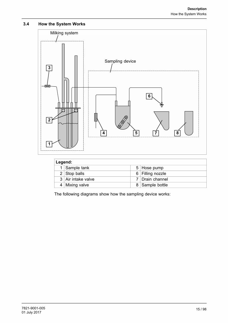
3.4 How the System Works
Milking system
Sampling device
1
2
3
4 5
6
7 8
Legend:
1 Sample tank 5 Hose pump
2 Stop balls 6 Filling nozzle
3 Air intake valve 7 Drain channel
4 Mixing valve 8 Sample bottle
The following diagrams show how the sampling device works:

Description
How the System Works
7821-9001-00501 July 201716 / 98
3.4.1 Mix sample
● During the milking process the sample tank is filled with about 2.5% of the actualmilk produced.
● After milking, atmospheric air flows through the open mixing valve and mixesthe sample in the sample tank.
3.4.2 Draw sample
● The hose pump (turning 100%) draws the sample out of the sample tank.

Description
How the System Works
7821-9001-00501 July 2017
17 / 98
3.4.3 Rinse lines with milk
● The hose pump (turning 60%) pumps the first part of the sample into the drainchannel.
3.4.4 Position filling nozzle
● The filling nozzle is positioned over the next sample bottle.

Description
How the System Works
7821-9001-00501 July 201718 / 98
3.4.5 Fill sample bottle
● The hose pump (turning 60%) fills the sample bottle with the sample.
3.4.6 Drain lines
● atmospheric air flows in through the open mixing valve and drains the intakeline.
● The hose pump (turning 60-100%) also drains the pressure line.
Description
How the System Works
7821-9001-00501 July 2017
19 / 98
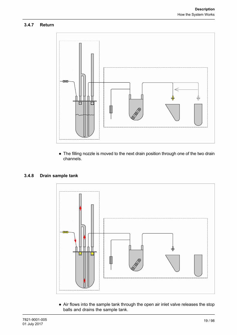
3.4.7 Return
● The filling nozzle is moved to the next drain position through one of the two drainchannels.
3.4.8 Drain sample tank
● Air flows into the sample tank through the open air inlet valve releases the stopballs and drains the sample tank.

Description
Technical Data
7821-9001-00501 July 201720 / 98
3.5 Technical Data
Geometric data
Dimensions(width x height x depth)
650 x 530 x 240
Weight of the case(without bottle rack)
24,5 kg
Electrical data
Electrical Connection 24 V DC
Manufacturer's plate
The rating plate is placed on the side of thesampling device.

Transport
Safety instructions for transport
7821-9001-00501 July 2017
21 / 98
4 Transport
Attention!
Women who are pregnant may not lift the sample case!The sample case weighs 24.5 kg. In accordance with Article 4.2.1 of theMaternity Protection Act pregnant women are not permitted to carry out workthat involves lifting, moving or transporting loads that exceed 10 kg withoutmechanical aids.► When possible, the case should be carried or moved by two persons.
There are handles on both of the short sides. Maintain a healthy posturewhen lifting and carrying. Keep your spine straight (study the illustration)
rightwrong
Attention!
The case contains sensitive items. Do not throw it!► Always place the case on the floor gently!
4.1 Safety instructions for transport
Read the ”Safety” section as well.
Special transport hazards:
● Projecting sharp edges may cause injury.
● If parts are stacked too high, the stack can become unstable and collapse.
● The highly inflammable packaging material represents a fire hazard - nakedflames and smoking prohibited!

Transport
Transport
7821-9001-00501 July 201722 / 98
4.2 Transport
The cable and hose must be stowed in the space provided in the bottle rack toensure they are not damaged during storage or transport.
Transport requirements:
● The two drain channels must go into thepositions provided.- The rear drain channel in the
positioning device- The front drain channel in the wall of
the box
● The sampling hose and connectingcable must be placed behind thepositioning device in the box.
Attention!
Trapped lines
The lines must not get trapped when the sampler is closed.
● The plug on the connecting cable mustbe fed through the positioning device tothe back.
● Alternatively, the plug may be fastenedto the positioning device with a cable tie.
● A bottle rack can also be transported inthe sampler.
Note
Not recommended! The total weight will then be more than 25 kg.
Transport
Transport
7821-9001-00501 July 2017
23 / 98
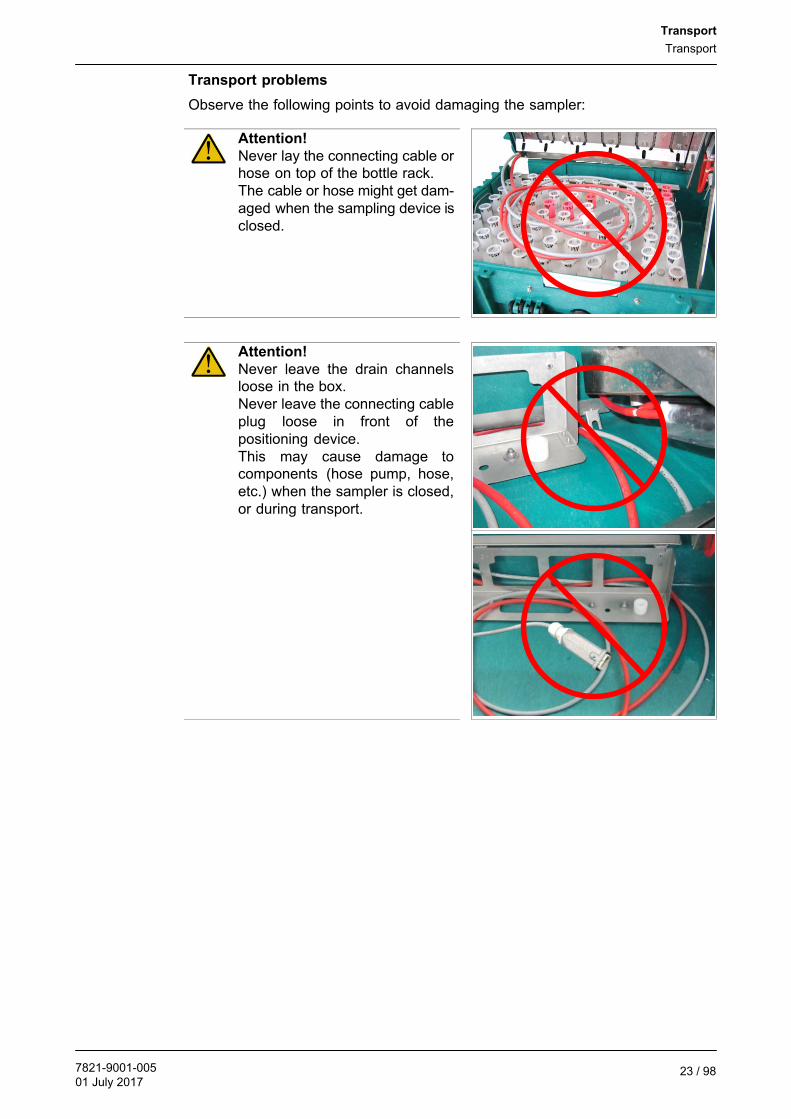
Transport problems
Observe the following points to avoid damaging the sampler:
Attention!
Never lay the connecting cable orhose on top of the bottle rack.The cable or hose might get damaged when the sampling device isclosed.
Attention!
Never leave the drain channelsloose in the box.Never leave the connecting cableplug loose in front of thepositioning device.This may cause damage tocomponents (hose pump, hose,etc.) when the sampler is closed,or during transport.

Transport
Information on disposing of packing material
7821-9001-00501 July 201724 / 98
4.3 Delivery
Check the goods supplied against the packing list enclosed for completeness anddamage.
2
4
3
1
Legend:
1 Milk sampling device2 Sample tank unit
3 Operating manual with installation instructions
4 Bottle rack to hold up to 80 sample bottles(Option)
4.4 Storage conditions
It is recommended that the device is stored in a dry, dust-free and frost-freeenvironment.
Please note!
The sampling device should be kept clean to extend its service life.
4.5 Information on disposing of packing material
After unpacking, the packing material must be handled properly and disposed ofcarefully in accordance with the valid local regulations on waste disposal andutilization.

Sampling device
Safety instructions for sampling
7821-9001-00501 July 2017
25 / 98
5 Sampling device
5.1 Special personnel qualification required for sampling
Sampling may only be carried out by specially qualified personnel in accordancewith the safety instructions.
Excellent knowledge of working with the automatic milking system and MView userinterface is needed to carry out sampling.
See also the section on ”Personnel qualification”.
5.2 Safety instructions for sampling
To prevent damage to property and/or life-threatening injury to personnel, thefollowing must always be observed:
● Use the product for its intended purpose only.
● Taking the wrong action when there is a fault may cause damage - so familiarizeyourself with the instructions on what to do if there is a fault.
Read the ”Safety” section as well.
Special risks involved in sampling:
● Incorrect use may lead to serious damage to property and/or life-threateninginjury to people.
Before taking samples, ensure you are familiar with:
● the operating and control elements,
● The equipment included
● The method of operation
● The immediate surroundings
Carry out the following checks before every start:
● Check and make sure that all media are suitable, connected and present.
● Check the product for any visible damage; immediately repair the fault found(noting the personnel qualification required) or contact the specialist dealer - theproduct may only be used if it is in perfect condition.
● Check and make sure that there are no objects or materials in the working areaif they are not necessary for operation.
During sampling:
● No safety equipment may be removed or taken out of operation duringsampling.
● Operating personnel should make sure that no unauthorized personnel are inthe working area.
Sampling device
Description of the operating elements
7821-9001-00501 July 201726 / 98
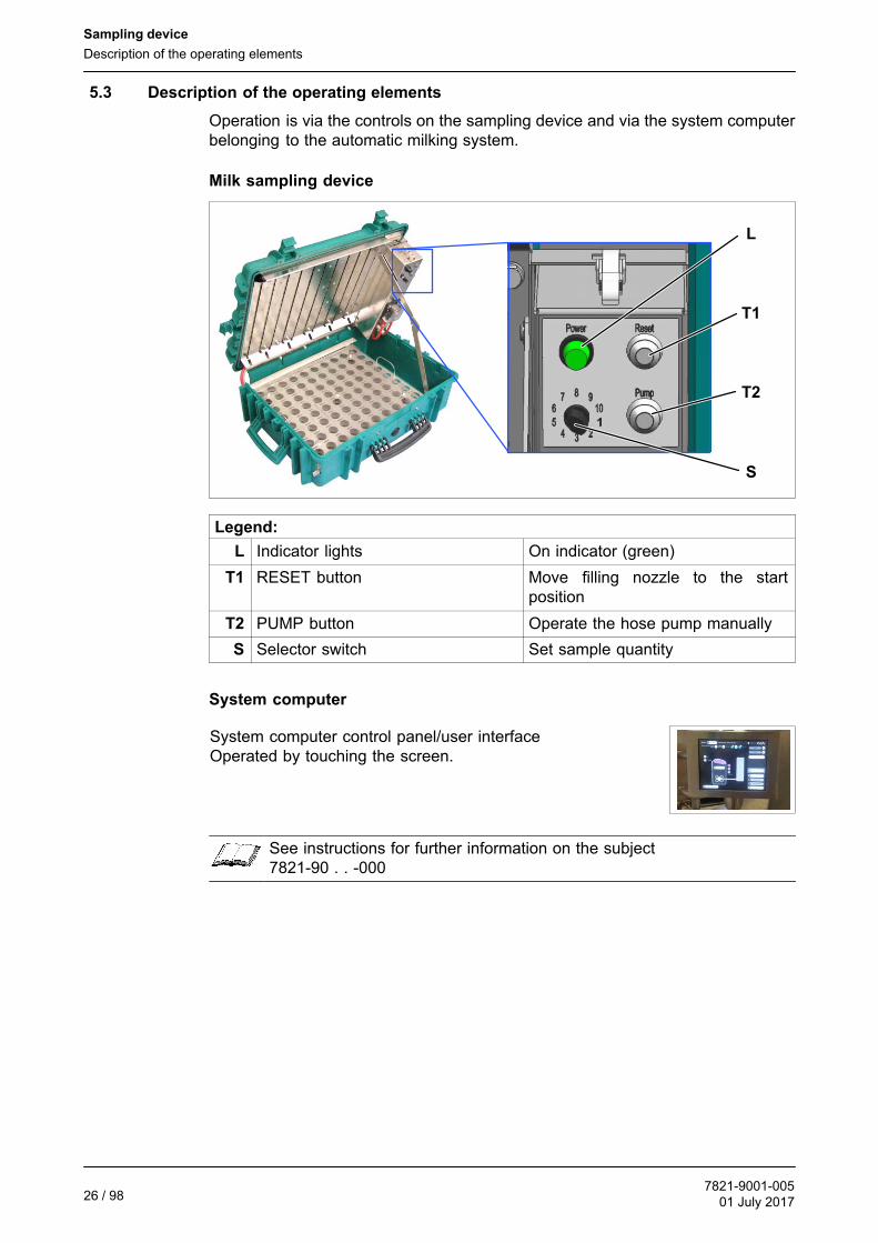
5.3 Description of the operating elements
Operation is via the controls on the sampling device and via the system computerbelonging to the automatic milking system.
Milk sampling device
T1
T2
L
S
Legend:
L Indicator lights On indicator (green)
T1 RESET button Move filling nozzle to the startposition
T2 PUMP button Operate the hose pump manually
S Selector switch Set sample quantity
System computer
System computer control panel/user interfaceOperated by touching the screen.
See instructions for further information on the subject7821-90 . . -000

Sampling device
Prepare for sampling
7821-9001-00501 July 2017
27 / 98
5.4 Overview of the steps involved in the sampling process
Warning!
Risk of crushing
There is a danger of being trapped between moving and stationary parts.► Standing in the danger area is strictly forbidden.
The following steps must be performed to ensure successful sampling. Detailedinformation on the individual steps is given below:
Prepare for sampling
● Stop automatic operation● Set up and connect the sampling device● Settings on the user interface of the automatic milking system
Take samples
● Start automatic operation● Note the box data
Interrupt sampling
● Stop automatic operation● Stop sampling● Change the bottle rack● Resume sampling● Resume automatic operation
End sampling
● Stop automatic operation● Stop sampling● Create the sample file● Transfer the sample bottles● Start the system clean● Disconnect and remove the sampling device● Resume automatic operation
5.5 Prepare for sampling
Note
Connect the sampling device to the automatic milking system before thesystem clean so that the milk-carrying parts of the installation can be cleanedagain before sampling.
Note
Milking boxes that are assigned to a common group of animals should carryout sampling together.It is important that the sampling processes begin at the same time.

Sampling device
Prepare for sampling
7821-9001-00501 July 201728 / 98
5.5.1 Stop automatic operation
Note
The system waits until a wash or milking process thatis still in progress ends before the milking box isblocked. This can be seen from the graphicanimation on the button.
LOCK BOX+++

Sampling device
Prepare for sampling
7821-9001-00501 July 2017
29 / 98
5.5.2 Set up and connect the sampling device
Set up the sampling device
Note
One sampling device is required for each milking box.
The sampling device is drained through theinternal drain channels.
● Set up the sampling device horizontallyor with a slight incline.
Slope
Set the sample quantity (depends on the capacity of the sample bottles)
The correct volumes for filling the 15 ml to 35 ml bottles must be set with the selectorswitch.
Note
The sample quantities actually filled may differ from the values given in thetable. They depend upon:● correct hose lengths● vacuum level● amount of wear on the hose pump
Sampling device
Prepare for sampling
7821-9001-00501 July 201730 / 98
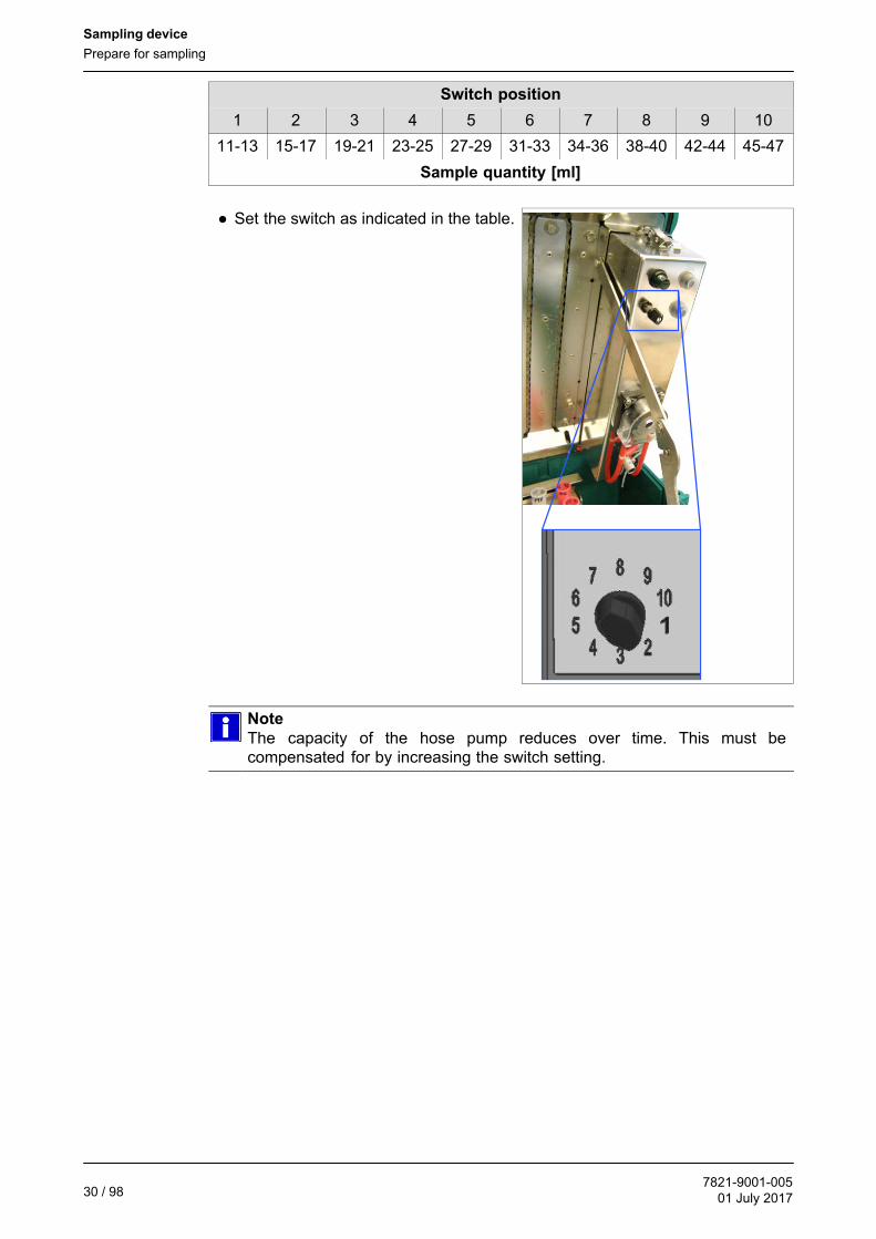
Switch position
1 2 3 4 5 6 7 8 9 10
11-13 15-17 19-21 23-25 27-29 31-33 34-36 38-40 42-44 45-47
Sample quantity [ml]
● Set the switch as indicated in the table.
Note
The capacity of the hose pump reduces over time. This must becompensated for by increasing the switch setting.

!!!
Sampling device
Prepare for sampling
7821-9001-00501 July 2017
31 / 98
Assemble the sample tank
The sample tank must be assembledbefore it is installed.
1
2
Attention!
Sample suction error
If the ball catch (1) is not seated properly under the lid, the balls do not blockthe holes in the lid properly when the sample is being sucked from the tank.► Check that the ball catch is seated properly(1).● Loosen the nuts, if necessary (2)● Align the ball catch and retighten the nuts(1, 2)
● Fit Y-hose connectors.

Sampling device
Prepare for sampling
7821-9001-00501 July 201732 / 98
● Fit hose and intake tube.
● Taper the intake tube at the bottom sothat it cannot attach itself to the bottomof the tank.
● Fit the hose and sealing ring to theintake tube so that the end of the hosecannot attach itself to the tank!
● Place tank on the cover and fasten.
Note
The arrow on the plug must be pointing up for sampling.

Sampling device
Prepare for sampling
7821-9001-00501 July 2017
33 / 98
Fit the sample tank in the milking system (Metatron)
The sample tank must be connected to themilk meter, air inlet valve and samplingdevice.
To connect the sample tank, remove thecover of the milking stall module and usethe chain snap hook to hang it on the eyebolt of the end frame, as shown (1,2,3,4).
1 2
3 4
Sampling device
Prepare for sampling
7821-9001-00501 July 201734 / 98
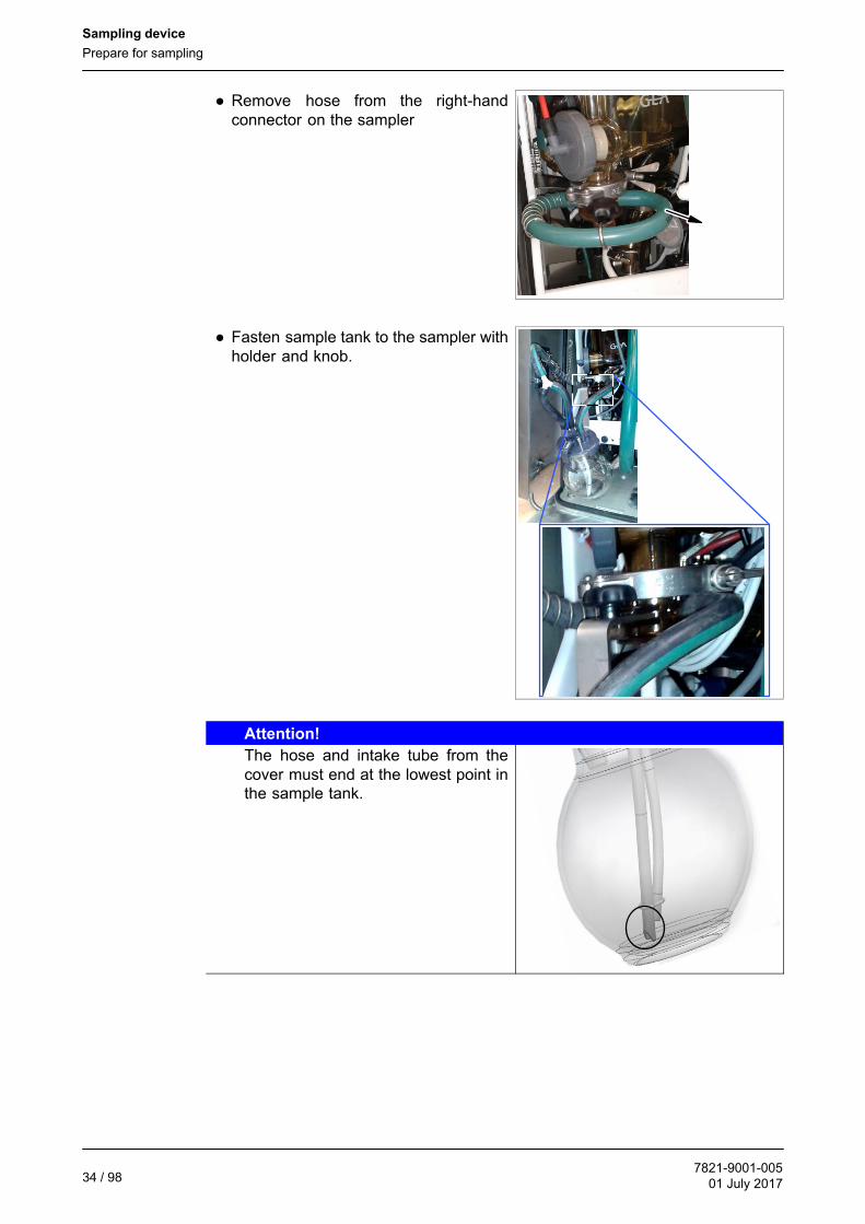
● Remove hose from the right-handconnector on the sampler
● Fasten sample tank to the sampler withholder and knob.
Attention!
The hose and intake tube from thecover must end at the lowest point inthe sample tank.
Sampling device
Prepare for sampling
7821-9001-00501 July 2017
35 / 98
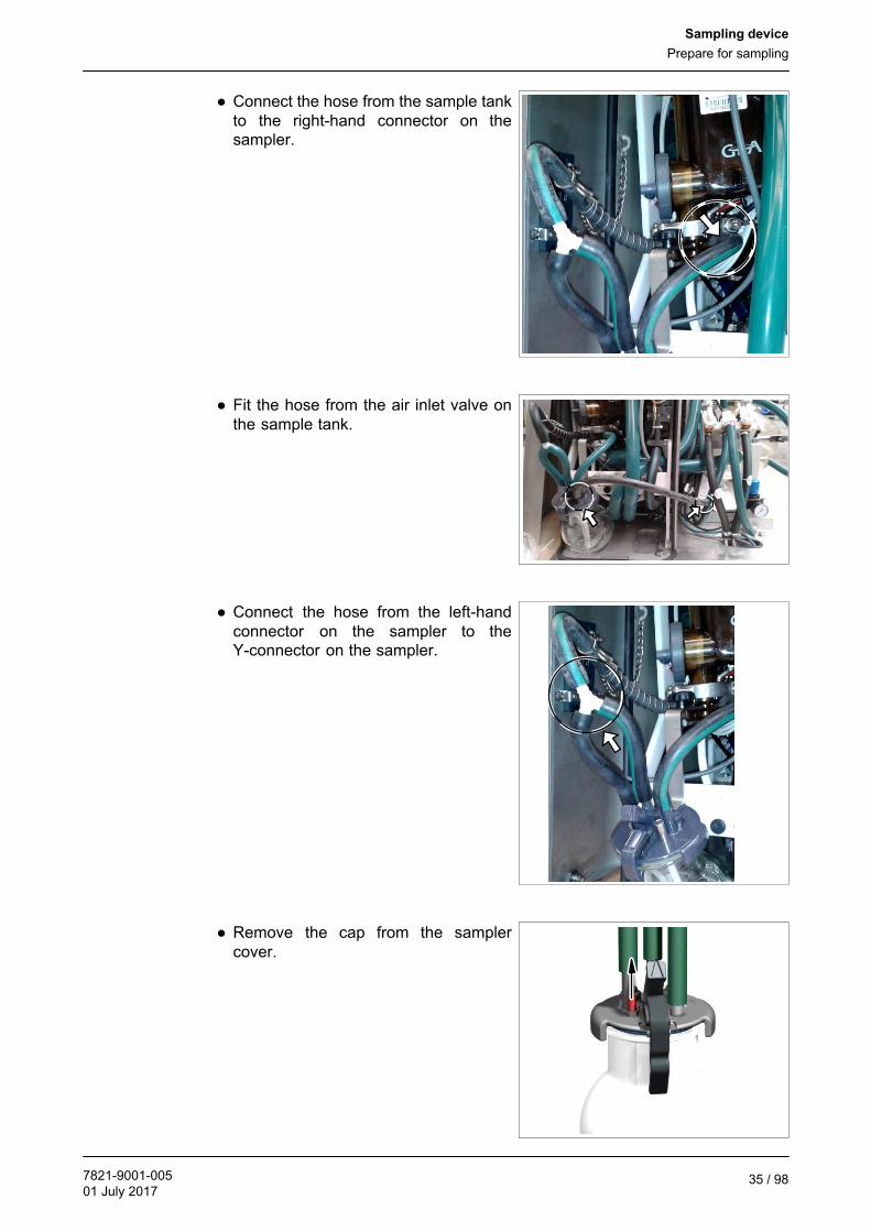
● Connect the hose from the sample tankto the right-hand connector on thesampler.
● Fit the hose from the air inlet valve onthe sample tank.
● Connect the hose from the left-handconnector on the sampler to theY-connector on the sampler.
● Remove the cap from the samplercover.

Sampling device
Prepare for sampling
7821-9001-00501 July 201736 / 98
● Connect the sampling tube on thesampling device to the sample tank.
Note
The sampling device's operating times are adapted to the original length ofthe sampling hose.Do not change the length of the hose!

Sampling device
Prepare for sampling
7821-9001-00501 July 2017
37 / 98
Insert the bottle rack
Before sampling begins, the drain channelsmust be fitted and a bottle rack inserted.
● Push the front drain channel onto theside of the case.
● Place the bottle rack in the positioningdevice.
Attention!
Make sure the bottle rack is theright way round.Note numbering!
Note
The bottle rack can only be inserted or removed without the rear drainchannel fitted.
Sampling device
Prepare for sampling
7821-9001-00501 July 201738 / 98
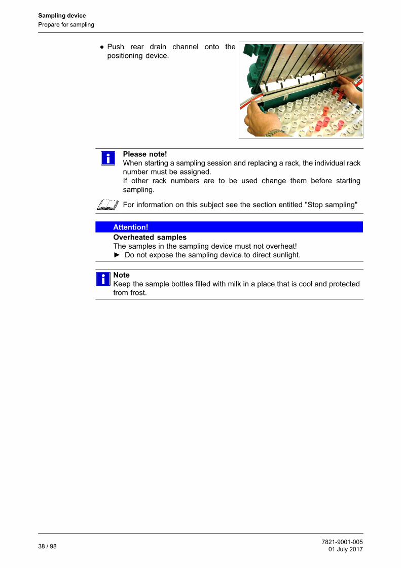
● Push rear drain channel onto thepositioning device.
Please note!
When starting a sampling session and replacing a rack, the individual racknumber must be assigned.If other rack numbers are to be used change them before startingsampling.
For information on this subject see the section entitled "Stop sampling"
Attention!
Overheated samples
The samples in the sampling device must not overheat!► Do not expose the sampling device to direct sunlight.
Note
Keep the sample bottles filled with milk in a place that is cool and protectedfrom frost.

Sampling device
Prepare for sampling
7821-9001-00501 July 2017
39 / 98
Connect the cable to the automatic milking system
The sampling device receives the electricity it needs from the automatic milkingsystem.
● Connect the 5-pole connector of thesampling case connection cable to theconnector of the monobox.
- The green indicator lamp on thesampling device will light.
● Press the "RESET" button.
- The filling nozzle will be heardmoving to the start position.
● Close the sampler cover.

Sampling device
Prepare for sampling
7821-9001-00501 July 201740 / 98
5.5.3 Settings on the user interface of the automatic milking system
Entering settings:
● Open menu item
1. Activate the Spanner symbol switch
- Sampling tab-> Start sampling+++START SAMPLING+++
2. To start sampling in MView.
● Enter the following settings:- Number of sample bottles per
bottle rack- Number of samples per animal- Boxes involved- Number of the bottle rack
● The right-hand screen must be filledout
Sampling then starts and the status is shown on the Box page.
SAMPLING MODE (40 /
80)+++
See instructions for further information on the subject7821-90 . . -001

Sampling device
Interrupt sampling
7821-9001-00501 July 2017
41 / 98
5.6 Take samples
Please note!
Carry out a system clean before starting sampling so that the milk-carryingparts of the installation can be cleaned once again.
For information on this subject see the section entitled "Cleaning"
5.6.1 Start automatic operation
Start sampling
● Open the menu item "Unlock box"+++UNLOCK BOX+++
Please note!
● If a cow produces less than 2 kg of milk (e.g. if the cluster isinadvertently removed), the data is not recorded and a sample is nottaken.
● If the teat cups are being attached manually during sampling, wait forat least one minute after the cow has left the box before attaching thecluster to the next cow.The sampling cycle does not start until the cluster has been removedand takes about one minute.
● A message is generated when all of the sample bottles in the samplingdevice have been filled.
5.6.2 Note the box data
Note the following data so that the data export can be checked:
● Sampling start time
● ID of the first cow in each box
5.7 Interrupt sampling
To change a bottle rack, sampling must be interrupted for the corresponding milkingbox.
5.7.1 Stop automatic operation
● Open the menu item "Lock box"+++LOCK BOX+++
Note
The system waits until a wash or milking process thatis still in progress ends before the milking box isblocked. This can be seen from the graphicanimation on the button.
LOCK BOX+++
5.7.2 Change the bottle rack
● Change bottle rack

Sampling device
Interrupt sampling
7821-9001-00501 July 201742 / 98
- Open the sampler cover.
- Remove the rear drain channel from the positioning device.
- Replace bottle rack.
- Push rear drain channel onto the positioning device.
- Press the "RESET" button.(the filling nozzle will be heard moving to the start position)
- Close the sampler cover.
● Enter the number of the new bottle rack.
- Press the button for entering anew rack number
- Enter the rack number
5.7.3 Resume automatic operation
● Open the menu item "Unlock box"+++UNLOCK BOX
Sampling device
End sampling
7821-9001-00501 July 2017
43 / 98
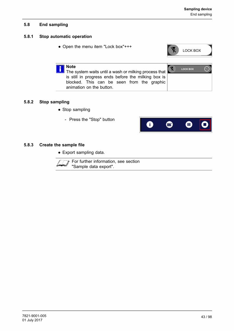
5.8 End sampling
5.8.1 Stop automatic operation
● Open the menu item "Lock box"+++LOCK BOX
Note
The system waits until a wash or milking process thatis still in progress ends before the milking box isblocked. This can be seen from the graphicanimation on the button.
LOCK BOX
5.8.2 Stop sampling
● Stop sampling
- Press the "Stop" button
5.8.3 Create the sample file
● Export sampling data.
For further information, see section"Sample data export".

Sampling device
End sampling
7821-9001-00501 July 201744 / 98
5.8.4 Transfer the sample bottles
The sample bottles in the bottle rack arefilled in this order at each individual milkingbox.
The sample bottles are assigned to the individual cows in the same order when thedata is exported.
Attention!
Incorrect sequencing when transferring the sample bottles to the laboratoryunit can result in incorrect test results!► When transferring the sample bottles to the laboratory unit, make sure
that the same order also corresponds to the order of examination in thelaboratory!
● Open the sampler cover.
● Transfer the sample bottles to thelaboratory unit.
- 1 → 1- 2 → 2- 3 → 3- ...
Example:Dutch laboratory unit
● Close the sampler cover.

Sampling device
End sampling
7821-9001-00501 July 2017
45 / 98
5.8.5 Start the system clean
The sampling device is cleaned with the short clean and the system clean.
This means that scheduled system cleans are performed even when a samplingsession is running.
Warning!
Risk of scalding
Hot steam generated during the main system clean can cause scalding if thedevice cover is left open!► Do not open the cover during the main system clean.
Note
It is not necessary to remove the bottle rack before the system cleanbegins.
Once sampling has been completed, start a system clean to clean the samplingdevice.
● Start system clean
Note
It is not necessary to remove the bottle rack before the system clean begins.

Sampling device
Displaying information about the current sampling process
7821-9001-00501 July 201746 / 98
5.8.6 Disconnect and remove the sampling device
Note
The red suction hose should be disconnected from the lid of the sample tankat the end of the system clean and placed in a vessel containing hot water.The pump in the sampling case should then be run manually for about 1minute. In this way, residual milk is flushed from the suction hose.
Once the system clean has ended, the sampling devices must be removed from allof the boxes.
● Carry out the steps described for setting up and connecting the device, but inreverse order.
Note
The sample tank unit remains with the sampling device.It is used to carry out measurements on that sampling device.
To extend its service life, the sampling device should be kept clean and itshould be stored in a dry place at room temperature.
5.8.7 Resume automatic operation
● Open the menu item "Unlock box"+++UNLOCK BOX
● Switch entry gates to all milking boxes to automatic mode.
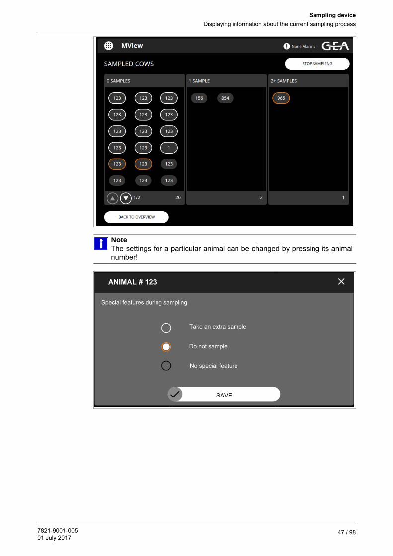
5.9 Displaying information about the current sampling process
The Info button (i) can be used to displayadditional information about the actualsampling.
The following information is displayed:
● The number of samples taken from each animal
● Whether an animal is excluded from the sampling process (orange border)
● Whether an additional sample should be taken from a particular animal (whiteborder)
Sampling device
Displaying information about the current sampling process
7821-9001-00501 July 2017
47 / 98
Note
The settings for a particular animal can be changed by pressing its animalnumber!
ANIMAL # 123
Special features during sampling
Take an extra sample
Do not sample
No special feature
SAVE

Sampling device
Clean
7821-9001-00501 July 201748 / 98
5.10 Clean
The milk-carrying parts of the installation are cleaned fully automatically by theautomatic milking system.
Note
Carry out cleaning directly before and after sampling.
Cleaning is performed with the individual phases of the system clean (pre-rinse,main clean and final rinse) and also with the short clean.
Warning!
Risk of scalding by hot cleaning solution!
Hot steam generated during the main system clean can cause scalding if thedevice cover is left open!► Do not open the cover during the main system clean.
● The hose pump runs several times for approximately 1 minute and remainsstationary briefly.
● The mixing valve opens and the hoses are drained by the incoming air.
Please note!
The red suction hose should bedisconnected from the lid of thesample tank at the end of thesystem clean and placed in avessel containing hot water. Thepump in the sampling case shouldthen be operated using the"Pump" button for about 1 minuteto flush residual milk from thesuction hose.
Also clean the sampling device manually, inside and out, after each session.
● Never clean electrical equipment with water or similar fluids.
Attention!
Damage can be caused if fluid gets in!
Protect any electrically conductive components from the effects of moisture.► Do not clean the sampling device with a high pressure cleaner or jet of
water!
● Clean the sampling equipment in the case lid with a damp cloth and then wipedry.
● Clean the plastic case and the stainless steel components in the bottom of thecase with a brush or sponge and warm cleaning solution.Next wipe with a clean, damp cloth and then wipe dry.
Note
Empty bottle racks and the drain channels can be cleaned in a dish washer.
Sample data export
7821-9001-00501 July 2017
49 / 98
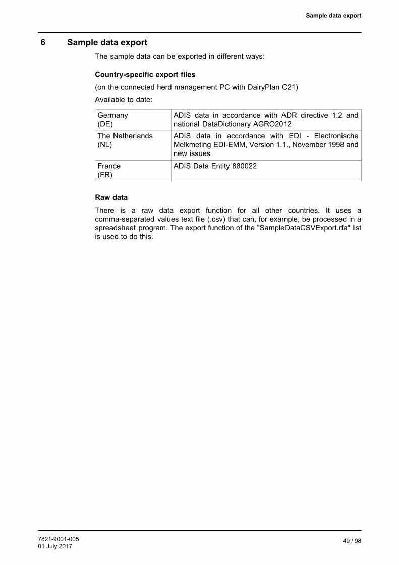
6 Sample data export
The sample data can be exported in different ways:
Country-specific export files
(on the connected herd management PC with DairyPlan C21)
Available to date:
Germany(DE)
ADIS data in accordance with ADR directive 1.2 andnational DataDictionary AGRO2012
The Netherlands(NL)
ADIS data in accordance with EDI - ElectronischeMelkmeting EDI-EMM, Version 1.1., November 1998 andnew issues
France(FR)
ADIS Data Entity 880022
Raw data
There is a raw data export function for all other countries. It uses acomma-separated values text file (.csv) that can, for example, be processed in aspreadsheet program. The export function of the "SampleDataCSVExport.rfa" listis used to do this.

Sample data export
To call up the program
7821-9001-00501 July 201750 / 98
6.1 To call up the program
Note
A country-specific sample data export can only be started on the herdmanagement PC.The IPC in the Monobox is only a display screen for MView. The animal datais on the HM-PC.
6.1.1 Sample data export for Germany (DE)
The sample data export is started on the herd management PC.
If the HM-D program module has been purchased (not obligatory for exportingsample data but necessary for importing milk control results, exporting controlmessages, etc.):
● Call up from the DP menu("Datenaustausch", "LKV-KopplungDeutschland" ["Data exchange", LKVconnection Germany"].
● Start the application DPMiko.
If it is not in the DPMenu, start the program DPMiko.exe directly from the DairyPlaninstallation folder with Windows Explorer or set up a link to DPMiko.exe and use thatto start the program later.
● In DPMiko select the button "Datenexport MIOne" [MIOne data export].
Note
The button is also used for the Monobox!

Sample data export
To call up the program
7821-9001-00501 July 2017
51 / 98
● Start the application "Robotermilchmengen_an_LKV" (based onDPRequest.exe).

Sample data export
To call up the program
7821-9001-00501 July 201752 / 98
6.1.2 Sample data export for Holland (NL)
The sample data export is started on the herd management PC.
Note
Make sure that "DPMenue_NL" is active in the DP menu ("M" button on theright next to the menus).
● Start sample data export with"Monstername Export" from the"Monstername" menu.
6.1.3 Sample data export for France (FR)
The sample data export is started on the herd management PC.
At this time it is not possible to call up from the DP menu.
Alternatively, a link file, with the name "lancerFR_Export_Donnees_Echantillonnage.lnk" is copied into the DairyPlan installationdirectory during installation.This file can be dragged from the DairyPlan directory onto the desktop so that it canbe used as a shortcut.
● Call up the application from the link as follows:
<DP-Installationspfad>\DPRequest.exe Export_Donnees_Echantillonnage /IS /NatFR
Note
This link only works if the DairyPlan program is installed in the directory"C:\DairyPln".This is the standard installation path on the herd management PC.Otherwise adjust the DP installation path in the link file "Properties".

Sample data export
To call up the program
7821-9001-00501 July 2017
53 / 98
6.1.4 Raw data export
The export format is a simple list of values. It is used for countries that do not definea specific format. This comma-separated values text file (.csv) can, for example, befurther processed using a spreadsheet program.
Note
Do not use the raw data export for countries that have a specially definedexport format; always use the country-specific sample data export.
Open the "SampleDataCSVExport.rfa" DairyPlan list from theDairyPlan folder to export the raw data.
Example:"C:\DairyPln\FactOrig\DE\SampleDataCSVExport.rfa"
1. The following data must be entered:● milking parlour number● sampling begin date● sampling begin time● sampling end date● sampling end time
2. The displayed data can then be exported using the menu.
● To do this, open the "File" menu and then the "Direct Transfer" submenu.
3. A text file containing the raw data is then stored in the DairyPlan folder.This file name is "SampleDataCSVExport <Date>.txt"
Example:"SampleDataCSVExport 170303 1345.txt" for a file that was created on 3.3.2017at 13:45.

Sample data export
Program execution
7821-9001-00501 July 201754 / 98
6.2 Program execution
If a country-specific sample data export is specified:
Another DPRequest application is started depending on the language set:
Germany(DE)
Robotermilchmengendaten_an_LKV
The Netherlands(NL)
ExportMonstername
France(FR)
Export_Donnees_Echantillonnage
The sequence is very similar. Only the fields that have to be completed for thecountry in question are shown.
If no country-specific sample data export is specified:
Use the raw data export.

Sample data export
Program execution
7821-9001-00501 July 2017
55 / 98
6.2.1 DPRequest application main dialogue
Enter the following:
● Farm number that should be included in the data.
● Restricted to groups or second group number (described in German as an"Abrechnungseinheit" "AE" - "accounting unit") if data is not to be sent for alllactating cows.
Please note!
If samples were taken from all the animals in a herd, these fields must beleft empty.
● Name of the target file. The following are pre-set:- DE: DPADISproben.ads- NL: MELKCTRL.EMM- FR: Export_Donnees_Echantillonnage.ads
Please note!
The name can be changed and a path can also be entered.
Example:A USB flash drive is displayed as drive "E".⇒ E:\DPADISproben090723.ads
If a path is not entered, the file will be saved in the DairyPlan installationdirectory (generally "C:\DairyPln").
Example (DE):
● Press the "OK" button to create the data and call up the next step.

Sample data export
Program execution
7821-9001-00501 July 201756 / 98
6.2.2 Farm data dialogue box
Depending on the language set, different fields are displayed that have to becompleted:
DE NL FR
● Farm number(Same value as in the main dialogue box, check. This farm"registration number" should generally be entered withoutany spaces. If necessary, check with the LKV or controlcentre.)
� � �
● Type of farm number(Ask the relevant LKV or control centre if necessary.)
�
● Second farm name(give the name that is to be included in the export data.)
�
● Postal code �
● Town / Address � �
● Telephone number �
● Data centre(code numbers and name are offered for the data centre.Only the code number is included in the data. If another datacentre has to be given, find the corresponding code numberand enter directly in the field).
�
● Laboratory(code numbers and name are offered for the laboratory.Only the code number is included in the data. If anotherlaboratory has to be given, find the corresponding codenumber and enter directly in the field)
�
� Field is displayed

Sample data export
Program execution
7821-9001-00501 July 2017
57 / 98
Example (DE):
Example (NL):
● Press the "Next" button ["Weiter"] to call up the next step.

Sample data export
Program execution
7821-9001-00501 July 201758 / 98
6.2.3 MLP (milk yield test) settings dialogue box (DE only)
Details have to be entered on the milk yield test:
● Test method (who performed the test)
● Test diagram (usually "S", occasionally also special solutions which are notlisted)
● Test interval (how often testing is performed)
● Milking frequency (always "R" for milking with a robot)
Note
The exact details should be agreed with the relevant control centre.
Example (DE):
● Press the "Next" button ["Weiter"] to call up the next step.

Sample data export
Program execution
7821-9001-00501 July 2017
59 / 98
6.2.4 Dialogue for single milking and sample export
There are two time periods for which data can be exported:
1. Export individual milkings for the period between the previous and the
present sampling (the sample bottle number is exported as zero)+++
(time period between the end of the previous official sampling and thebeginning of the current sampling)
Most control centres use milking data from this time to establish a yield assessment.To ensure that these data do not include any sample bottle or sample box numbersthat come from other sampling operations (for health monitoring for example) andmight confuse the control centre computer, these data are exported in DairyPlanso that there are always zeros for the sample numbers.
Only the start of this time period (date and time) is entered, this corresponds to theend of the previous sampling.The end of the time period is calculated based on the start of the time period in thefollowing section.
Note
Remove the tick if no data are to be exported from this period.
2. Export individual milkings from sampling with sample bottle numbers
(enter the date and time)+++
(time period of the actual sampling)
Single milk output data, with the bottle and box numbers saved, are exported here.
● Enter the beginning and end of the time period (date and time.
Example (DE):

Sample data export
Program execution
7821-9001-00501 July 201760 / 98
Example (NL):
Example (FR):
Attention!
Compare the bottle numbers
The bottle numbers for the animals and the numbers on the bottles in thesample box must correspond.► Use the display screen to check carefully.

Sample data export
Program execution
7821-9001-00501 July 2017
61 / 98
The functions of the data display buttons are described below.
● Print a sample data document.+++
Start the process by clicking on the corresponding button (below date/time ofthe sampling period).
Note
The printed sample data document is added to the sample box (or bottlerack) and is sent with it to the laboratory.The sender of the samples and the number of boxes and bottles can be takenfrom the printed document.

Sample data export
Program execution
7821-9001-00501 July 201762 / 98
Milk dry animals and colostrum cows+++
(only for sample data export Germany)
If this function is activated, a segment is added to the data which registers the dryand colostrum animals with the LKV.These data are taken from the sampling data for conventional dairy farms and isreferred to as "Entity 880033" by the data centres.
Note
Not all computer centres can process this data for a milking robot.Check in advance whether your data centre can read the data entity 880033from a farm that uses robots.
Attention!
Data about dry animals and colostrum cows can only be created on thesampling day.► If data is reported at a later date, omit the data entity 880033 because the
program only exports the dry cows and colostrum animals that arecurrently in the data set.
● Start data export with the "OK" button.

Sample data export
Program execution
7821-9001-00501 July 2017
63 / 98
"Anzeige Betrieb + allgemeine Daten" button ["Display farm + general data]
(DE and NL only)
This button can be used to display the data to be exported (general details of thefarm or herd):
● Click on the button.
● "DPList" will open in a separate window.
Example (DE):
Display data that are to be sent to the control centre as "Entity 880001Betriebsdaten" (farm data).
Example (NL):
Display data that are to go to the control centre as "Entity 204008 GebeurtnisBedrifsgegevens" (farm data) and "Entity 204010 Gebeurtnis Registratie" (list ofanimals on the farm).

Sample data export
Program execution
7821-9001-00501 July 201764 / 98
"Daten anzeigen" button ["display data"] for both time periods.
This button can be used to display the rows of data for the corresponding period:
● Click on the button.
● "DPList" will open in a separate window.
Example (DE):
Displays data that are to be transmitted as "Entity 880022 Einzelgemelke" (singlemilk output).
Note
The ear marker numbers of all animals for which data will be exported mustbe clearly entered as a 15-figure number.
Example (NL):
Display data that are to be transmitted as "Entity 204250 Gebeurtnis MonsternameKoe".

Sample data export
Program execution
7821-9001-00501 July 2017
65 / 98
Note
For France, the data are transmitted in an amended form of the German"Entity 880022".
Note
The (1st) period after the end of the previous sampling (usually severalweeks) may be too large to be able to display all of the rows of data in theDPList screen.To check all of the rows of data, use DPList to export the data ("File" menu,"Transfer file") to an ASCII file or an Excel table.(see DPList program for the exact process)If the computer has a printer installed, alternatively all of the pages can beviewed with "File" and "Page view".
Attention!
Data processing error caused by unofficial samplings
There must be a zero for all of the sample box and bottle numbers for theperiod after the end of the previous sampling.This is important because unofficial samplings may interfere with theprocessing of the data in the laboratory.► The number of bottle numbers listed must be the same as the number of
sample bottles filled.
"Additional Data Milk Control" button (NL only)
For exporting data in Holland, it is possible to mark individual, conspicuous animals(sick animals for example) with a specific code.Although that code will then be in all of the single milk output rows for that animal.It is not possible to enter it only for specific single outputs.
The code is entered with the program in "Details", "Letztes Gemelk" ["Last Milking"]dialogue page in the field "Zusatzcode (PRLMU)" ["Additional code"].
A screen showing the animals with a code can be called up with the buttondescribed here:
● Click on the button.
● "DPList" will open in a separate window.
Note
The exact codes can be obtained from the relevant control centre.
Sample data export
Program execution
7821-9001-00501 July 201766 / 98
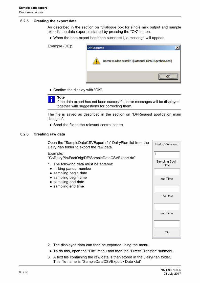
6.2.5 Creating the export data
As described in the section on "Dialogue box for single milk output and sampleexport", the data export is started by pressing the "OK" button.
● When the data export has been successful, a message will appear.
Example (DE):
● Confirm the display with "OK".
Note
If the data export has not been successful, error messages will be displayedtogether with suggestions for correcting them.
The file is saved as described in the section on "DPRequest application maindialogue".
● Send the file to the relevant control centre.
6.2.6 Creating raw data
Open the "SampleDataCSVExport.rfa" DairyPlan list from theDairyPlan folder to export the raw data.
Example:"C:\DairyPln\FactOrig\DE\SampleDataCSVExport.rfa"
1. The following data must be entered:● milking parlour number● sampling begin date● sampling begin time● sampling end date● sampling end time
2. The displayed data can then be exported using the menu.
● To do this, open the "File" menu and then the "Direct Transfer" submenu.
3. A text file containing the raw data is then stored in the DairyPlan folder.This file name is "SampleDataCSVExport <Date>.txt"

Sample data export
Program execution
7821-9001-00501 July 2017
67 / 98
Example:"SampleDataCSVExport 170303 1345.txt" for a file that was created on 3.3.2017at 13:45.
The following data fields will be exported:
- Barn number (cowNr)- Ear marker number (earTag)- Milking box number (boxNr)- Date of milking (date)
The date is shown according to the language (in the order Day/Month/Year).- Time of milking (time)- Quantity of milk from this milking (yield)
The decimal marker (point or comma) is shown according to the language.- Box number (rackNr)- Bottle number (bottle)
Note
The first row lists the abbreviated designations of the data fields.The values are separated from each other by a semicolon.
Example:
cowNr;earTag;boxNr;date;time;yield;rackNr;bottle3;276000579311111;2;12.01.09;7:34;16,42;12345;15;276000579611112;5;12.01.09;8:04;21,85;12345;2
● Send the file to the relevant control centre.

Operating faults
Safety Instructions for Troubleshooting
7821-9001-00501 July 201768 / 98
7 Operating faults
If necessary, please contact your nearest authorized technical dealer.
7.1 Special personnel qualification required for troubleshooting
Troubleshooting may only be performed by specially qualified personnel inaccordance with the safety instructions.
They must be trained in operating and setting up the sampler, have experience ofworking with it and must have read and understood this manual.
See also the section on ”Personnel qualification”.
7.2 Safety Instructions for Troubleshooting
To prevent damage to property and/or life-threatening injury to personnel, thefollowing must always be observed:
● First of all, prevent the product from being restarted accidentally.
● Ensure that safe disconnection can be carried out by a second person at anytime.
Read the ”Safety” section as well.
Special dangers involved in troubleshooting:
● If energy sources are switched on unintentionally this may lead to seriousdamage to property and/or life-threatening injuries to people and animals.
● Electrostatic processes may damage electronic components.
Attention!
Electrostatic discharge!
Circuit boards can be damaged by electrostatic discharge.► Avoid electrostatic charge (e.g. from clothing) and only touch the edges
of circuit boards.

!!!
Operating faults
Possible faults and troubleshooting help
7821-9001-00501 July 2017
69 / 98
7.3 Possible faults and troubleshooting help
Malfunction Possible cause Solution
Green indicator lampdoes not come on
Cable not connected
Faulty LED
Check and connectcorrectly if necessary
Replace LED
No sample in the samplebottle
Sampling hose is notconnected correctly, or isblocked, kinked or torn
Check and replace ifdamaged
Hose pump defective Replace faulty parts
Crimp valve and/or airinlet hose for mixingopen
Check and replace anydefective parts
Too much or too littlesample in the samplebottle
Sampling hose is thewrong length
Use the original length
Wrong switch position Reset the quantity
To little sample in thesample bottle
Reducing hose pumpcapacity
Sampling hose (red) iskinked
Readjust the quantitywith the switch
Replace the hose of thehose pump
Adjust the samplinghose until it is no longerkinked
Air inlet hose for mixingis leaking
Check and replace ifdamaged
Suction hose (red) iscaseated
Disconnect the suctionhose from the tank andhold it in a vesselcontaining hot water; runthe pump manually forone minute to flush thehose.
Different samplevolumes in samplebottles
Suction hose(transparent) is suckingitself onto the tank.
Push the suction hose inthe tank up to the lidnozzle and attach it tothe draw tube using asealing ring
Sample is missing thesample bottle
Chain and/or chainsprockets are worn out
Limit switch is beingpassed
The encoder of the drivemotor is faulty
Replace faulty parts
Check and adjust thelimit switch trigger point
Check the encoder, andreplace the motor, ifnecessary
Operating faults
Possible faults and troubleshooting help
7821-9001-00501 July 201770 / 98
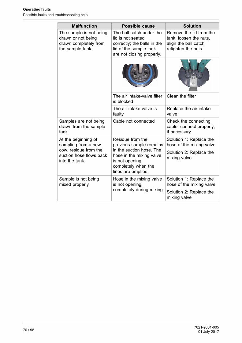
SolutionPossible causeMalfunction
The sample is not beingdrawn or not beingdrawn completely fromthe sample tank
The ball catch under thelid is not seatedcorrectly; the balls in thelid of the sample tankare not closing properly.
Remove the lid from thetank, loosen the nuts,align the ball catch,retighten the nuts.
The air intake-valve filteris blocked
Clean the filter
The air intake valve isfaulty
Replace the air intakevalve
Samples are not beingdrawn from the sampletank
Cable not connected Check the connectingcable, connect properly,if necessary
At the beginning ofsampling from a newcow, residue from thesuction hose flows backinto the tank.
Residue from theprevious sample remainsin the suction hose. Thehose in the mixing valveis not openingcompletely when thelines are emptied.
Solution 1: Replace thehose of the mixing valve
Solution 2: Replace themixing valve
Sample is not beingmixed properly
Hose in the mixing valveis not openingcompletely during mixing
Solution 1: Replace thehose of the mixing valve
Solution 2: Replace themixing valve

Maintenance
Safety instructions for maintenance
7821-9001-00501 July 2017
71 / 98
8 Maintenance
If necessary, please contact your nearest authorized technical dealer.
8.1 Special personnel qualification required for maintenance work
Maintenance work may only be performed by specially qualified personnel inaccordance with the safety instructions.
They must be trained in operating and setting up the sampler, have experience ofworking with it and must have read and understood this manual.
See also the section on ”Personnel qualification”.
8.2 Safety instructions for maintenance
To prevent damage to property and/or life-threatening injury to personnel, thefollowing must always be observed:
● Only use original spare parts / original wearing parts / original accessories.In the case of products by other manufacturers it cannot be ensured that theyhave been designed and produced from the point of view of loads and safety.
● All of the steps involved in the maintenance work must be worked through in theorder specified.
● The maintenance work specified in the instructions (adjustment, cleaning,lubrication, inspection, etc.) must be performed at the times specified.
● Maintenance work should only be performed with the tools envisaged for thispurpose.
● Also note the special information in this manual for the individual components.
● Only use the operating media specified.
● Immediately replace any components that are not in perfect condition.
Read the ”Safety” section as well.
Before carrying out maintenance work, make sure of the following:
● Before performing any work on electrical installations or equipment(components, housing, etc.) switch off all power supplies and make sure theycannot be switched back on again. Put up a sign warning against switching themback on again.
● all components have cooled to room temperature

Maintenance
Safety instructions for maintenance
7821-9001-00501 July 201772 / 98
Special risks involved in maintenance work:
● Serious damage to property might occur if incorrect replacement or wearingparts are installed.
● If energy sources are switched on unintentionally, this may lead to seriousbodily injury or damage to property.
● Electronic components may be damaged by electrostatic processes.
Note
Only touch the edge of the printed circuit board and avoid static caused forexample by clothing.
On completion of the maintenance work, check that:
● The installation values set before the work was performed have not beenchanged by the work (see settings report).
● all screwed connections that were loosened earlier have been tightened.
● All safety devices, guards, tank covers, etc. that were removed previously havebeen put back correctly.
● All safety equipment is working perfectly again.
● Have all of the tools, materials and other equipment that were used beenremoved from the working area again?
● Operation has been checked after maintenance work has been completed orparts replaced. Produce a full test report if necessary.

Maintenance
Inspections and preventive maintenance
7821-9001-00501 July 2017
73 / 98
8.3 Inspections and preventive maintenance
Interval*(samples filled)
Description Action
After every session Milk sampling device Clean thoroughly inside and out
every six months(7500-9000)
Hose pump hose replace
once a year(15000-18000)
All hoses, wearing parts replace
Filling positionCheck and adjust limit switch ifnecessary
every 3 years(45000-60000)
Chain, driving pinion, chainsprockets
Check, replace if necessary
Hose pump replace
* Period of constant use (several times a week)
Carry out regular checks on electrical equipment:
● Tighten any loose connections
● Replace damaged lines or cables immediately
● Close off any cable openings that are not being used
8.3.1 Replacing wearing parts on the sample tank
Wearing parts come together in a set ofreplacement parts.
● Replace wearing parts
7161-9904-070
8.3.2 Replacing the hose pump hose
Replace the hose every year to ensure reliable operation.
Attention!
Only replace the hose when the hose pump is off.
Attention!
Only replace the hose when the hose pump is off.► Switch off the hose pump before replacing the hose.
● Pull the hose out from the hose pump.

!!!
Maintenance
Inspections and preventive maintenance
7821-9001-00501 July 201774 / 98
● Undo the three screws in the housingcover.
● Remove the housing cover form thehose pump.
● Take the hose out of the housing cover.
● Insert a new hose in the housing cover.
● Screw the housing cover onto the hose pump.
Attention!
Not fitting the housing cover properly can damagethe hose or cause fluctuation of the pump output.► Make sure that the housing cover is positioned
correctly between the guide marks (x)!- The housing cover must be flush x
● Reconnect the hoses to the outside of the hose pump.
The pump can now be used again.

Maintenance
Inspections and preventive maintenance
7821-9001-00501 July 2017
75 / 98
Note
After replacing the hose, reset the sample quantities required on the unit andcarry out a trial run.

Maintenance
Inspections and preventive maintenance
7821-9001-00501 July 201776 / 98
8.3.3 Replacing the chain and sprockets
The chain comes correctly pre-tensioned from the factory.
It is not necessary to re-tension the chain because of the very slight wear.
As a rule the chain will not have to be changed for several years.
Warning!
Danger from automatic start
The conveyor chain can start to move when work is being carried out.There is a risk of crushing and electric shock.► Disconnect the cable from the power supply before starting the work.
● Undo the four screws holding thesampling equipment in the lid.
● Turn the sampling equipment out of thelid so that the chain is on top.
● Loosen the threaded pin on thesprocket (drive) with a spanner.
● Place a spanner on the square of thechain tensioner and loosen the chain.

Maintenance
Inspections and preventive maintenance
7821-9001-00501 July 2017
77 / 98
● Remove the sprocket from the driveshaft.
● Replace any defective parts (e.g. chain or sprockets).
● Place sprocket with chain on the drive shaft, loosening the chain with thespanner.
● Turn the sprocket until the threaded pinis pointing towards the flat surface of thedrive shaft.
● Position the sprocket at the requiredheight on the drive shaft.
= =
● Tighten the threaded pin on thesprocket (drive) with a spanner.
● Re-assemble the sampling device.

Maintenance
Inspections and preventive maintenance
7821-9001-00501 July 201778 / 98
8.3.4 Checking and adjusting the limit switch trigger point
The trigger point may change over time and therefore has to be checked regularly.
● Connect the cable to the automatic milking system.
● Press the "RESET" button.
- The filling nozzle will be heard moving to the start position.
● Open the catch on the top of the cover.
● Briefly press the button on the right ofthe electronic card.
- The filling nozzle moves oneposition further.
● Check the nozzle's first filling position.
- The filling positions are marked bynotches.
● Press the "RESET" button.
- The filling nozzle moves back to the start position.

Maintenance
Inspections and preventive maintenance
7821-9001-00501 July 2017
79 / 98
● Press and hold down the button on theright of the electronic card.
- The filling nozzle travels to position41.
● Check the nozzle's filling position.
- The deviation may not be more than +/- 1.5 mm.
If the first filling position is not correct:
Warning!
Danger from automatic start
The conveyor chain can start to move when work is being carried out.There is a risk of crushing and electric shock.► Disconnect the cable from the power supply before starting the work.
● Take the sampling device out of the lidas described in "Replacing the chainand sprocket" and turn over.
- The limit switch is accessible.
● Change the position of the limit switchso that the filling nozzle is exactly on themarking for the first filling position.
● Re-assemble the sampling device.
● Check the nozzle's first filling position again as described above.
decommissioning
Final decommissioning/disposal
7821-9001-00501 July 201780 / 98
9 decommissioning
Decommissioning may only be performed by specially qualified personnel inaccordance with the safety instructions.
See also the section on ”Personnel qualification”.
9.1 Safety instructions for decommissioning
To prevent damage to property and/or life-threatening injury to personnel, thefollowing must always be observed:
● All of the steps involved in the decommissioning work must be worked throughin the order specified.
● First of all, make the operating area for decommissioning completely safe.
● Make sure that operating media are disposed of without harming theenvironment.
Read the ”Safety” section as well.
Special risks during initial commissioning:
● Leaking lubricants, solvents, preservatives, .... can cause injury if they comeinto direct contact with the skin.
● Components which have not been removed correctly may fall off or twist.
● Exposed sharp-edged components/tools/.... may cause injury.
9.2 Temporary decommissioning
● Stop sampling.
To extend its service life, the sampling device should be kept clean and it shouldbe stored in a dry place at room temperature.
9.3 Final decommissioning/disposal
You are strongly advised to contact the supplier if the system is to bedecommissioned.
● Stop sampling.
● Take components out of the automatic milking system.(in the reverse order as described in the section entitled ?Prepare forsampling?)
After final decommissioning, handle all components properly and dispose of themin accordance with valid local regulations on waste disposal and utilisation.
Note
The system contains components (metals, electrical components, plastics,etc.) which are not biodegradable.

Spare Parts
Milk sampling device
7821-9001-00501 July 2017
81 / 98
10 Spare Parts
10.1 Milk sampling device
Item Part no. Description
7801-2503-000Milk sampling device
(without bottle rack)MIone Metatron
0020 7801-2187-070 Bracket, complete
0030 7821-2503-000 Sampler complete
0040 0019-5575-300 Saucer-head screw M8x25
0050 0026-1345-300 washer 8,4
0060 0019-9101-300 Cheesehead screw M4x20
0070 Milk sampling device MIone Interrior
0080 7800-0025-657 Cover holder
0090 7800-0025-663 Distance bush M8x56
0100 0019-6901-300 Hexagon head bolt M8x16
0120 0026-0439-300 washer 8,4x24x2
0130 7800-0025-678 Lock washer 7
0150 7801-1268-020 Drain channel, welded Duo Compact II
0160 7801-1268-000 Drain channel, welded rear
0170 0019-9100-300 Cheesehead screw M4x16
0180 0026-0429-300 washer 5,3x15x1,2
0190 0026-1362-300 washer 4,3
0200 0013-0310-300 Hexagon Head Nut M4
0210 0019-6845-300 Hexagon head bolt M6x25
0220 0026-0922-300 washer 6,4x18x1,6
0230 0013-0294-300 Hexagon Head Nut M6
See corresponding parts list/drawing for further breakdown of components.

Spare Parts
Milk sampling device
7821-9001-00501 July 201782 / 98
10.1.1 Sampler complete
Item Part no. Description
7821-2503-000 Sampler complete
0020 7821-5588-000 Box D128x163 - 1L
0030 Cover for sampler complete
0040 x 0018-0380-848 x Pipe (170 mm)8x1(available by the metre)
0050 0018-4376-898 x tube (160 mm)4x1,5(available by the metre)
0060 7021-7106-058x Milk hose, silicone
8,5x3,75(x25.000) Sil gn
0070 7021-7106-050 8,5x3,75x225 Sil gn
0160 0018-5324-820 Y-hose connector 10
0170 7021-7106-058 Milk hose, silicone (110 mm)8,5x3,75(x25.000) Sil gn
0180 7021-7106-058 Milk hose, silicone (120 mm)
0190 0026-2249-890 Cap 4x15
0200 0007-1974-700 Sealing ring 10x2
x - Wear part, see section on ”Maintenance” for maintenance interval
Included in set of spare parts (7821-9905-030).
See corresponding parts list/drawing for further breakdown of components.

Spare Parts
Milk sampling device
7821-9001-00501 July 2017
83 / 98
Cover for sampler complete
120
50 60 20 100 40 30
70
90
130
110
160
150 170
Item Part no. Description
7821-2758-000 Cover for sampler complete
0020 7161-2298-010 Guide piece
0030 7161-5566-000 Lever
0040 7161-1467-000 x Sealing panel 36x20xø4
0050 0007-2060-700 x Sealing ring 66x6
0060 0007-1818-700 x Sealing ring 9x2
0070 0013-0311-300 Hexagon Head Nut M5
0090 7821-2084-230 Bracket 93,1x114,3x20 T3
0100 7161-6708-000 Plug completeø12 Metatron(with 110, 130)
0110 0007-2509-700 x Sealing ring 8x2
0120 0026-1508-890 Ball 12mm
0130 0007-1974-700 x Sealing ring 10x2
0150 0013-0276-300 Hexagon Head Nut M6
0160 7801-4807-000 connector RMS
0170 7051-2045-000 hose connector
- 7821-9905-030 Set of spare parts
x - Wear part, see section on ”Maintenance” for maintenance interval
Included in set of spare parts (7821-9905-030).
See corresponding parts list/drawing for further breakdown of components.

Spare Parts
Milk sampling device
7821-9001-00501 July 201784 / 98
Clip complete
10
20
40
Item Part no. Description
7161-3270-000 Clip complete
0010 7161-2097-140 Clamp øo69x17
0020 7161-2653-000 Clamp 55xø4
0040 0007-3239-890 x Sealing ring25 Tri-Clampøo50,5xøi25,3
x - Wear part, see section on ”Maintenance” for maintenance interval
Included in set of spare parts (7821-9905-030).

Spare Parts
Milk sampling device
7821-9001-00501 July 2017
85 / 98
Set of spare parts
20
30
40
70
60
50
10, 80, 90,
100, 150
120
130
140
110
Item Part no. Description
7821-9905-030 Set of spare parts
0010 7021-7106-060 Milk sampler hose, silicone 8,5x3,75x320 Sil gn
0020 0007-3239-890 Sealing ring D1in Tri-Clamp Sil
0030 0007-2509-700 Sealing ring 8 X 2
0040 0007-1974-700 Sealing ring 10x2
0050 7161-1467-000 Sealing panel 36x20xD4
0060 0007-2060-700 Sealing ring 66 x 6
0070 0007-1818-700 Sealing ring 9 x 2
0080 7021-7106-058 Milk sampler hose, silicone 8,5x3,75(x25.000) Silgn (210 mm)
0090 7021-7106-058 Milk sampler hose, silicone 8,5x3,75(x25.000) Silgn (110 mm)
0100 7021-7106-058 Milk sampler hose, silicone 8,5x3,75(x25.000) Silgn (120 mm)
0110 0018-4376-898 tube ID4xOD7(xL25.000)Sil tp (160 mm)
0120 0018-0380-848 Pipe OD8xID6 Pla na (170mm)
0130 0026-2249-890 Cap ID4 Pla rd
0140 0018-5324-820 Y-hose connector OD10x90Deg Pla
0150 7021-7106-050 Milk sampler hose, silicone 8,5x3,75x225 Sil gn
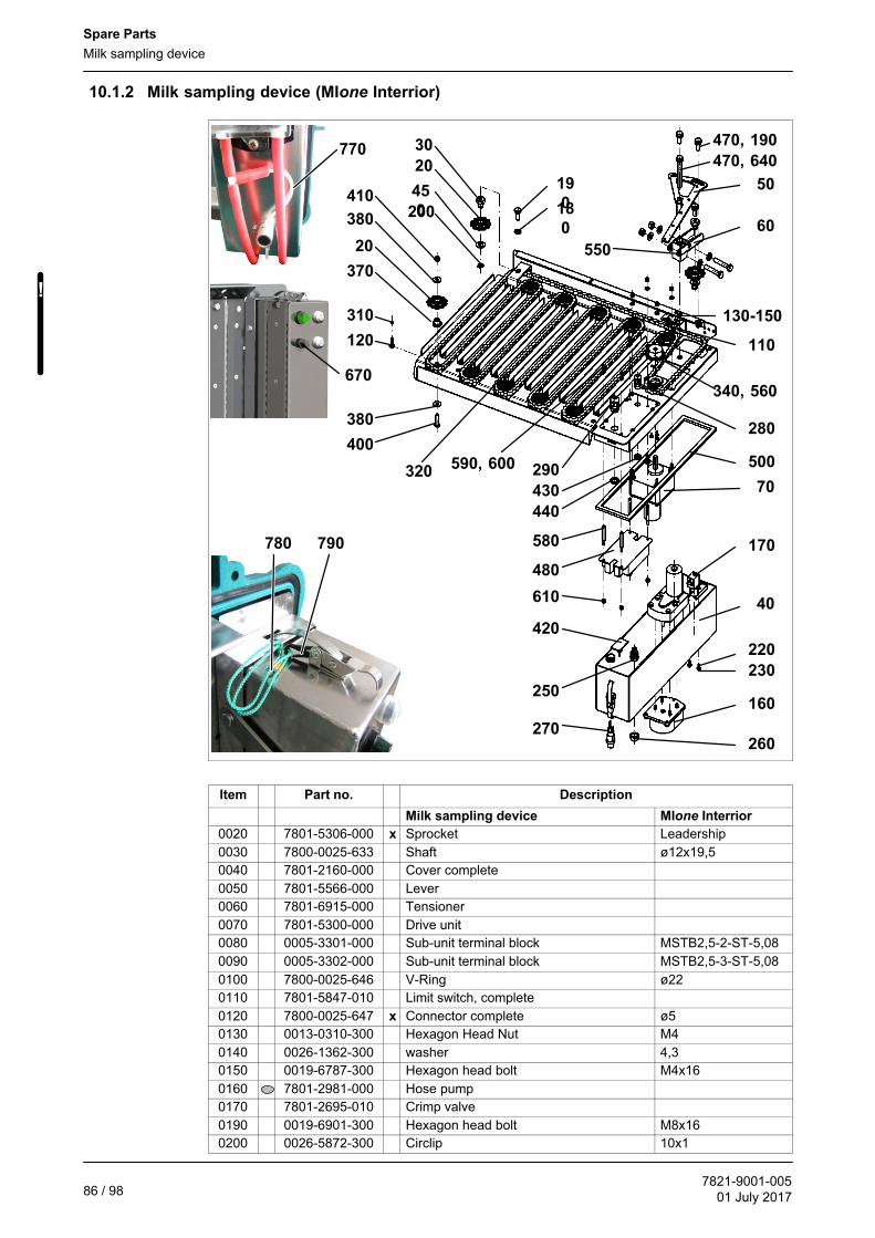
!!!
Spare Parts
Milk sampling device
7821-9001-00501 July 201786 / 98
10.1.2 Milk sampling device (MIone Interrior)
20
30
40
70
110120
130-150
160
170
18
0200
220
230
250
260270
280
290
310
320
340, 560
370
20
380
400
380
420
430
440
45
0
470, 190
470, 640
480
500
550
580
590, 600
610
4105019
0
60
780 790
770
670
Item Part no. Description
Milk sampling device MIone Interrior
0020 7801-5306-000 x Sprocket Leadership
0030 7800-0025-633 Shaft ø12x19,5
0040 7801-2160-000 Cover complete
0050 7801-5566-000 Lever
0060 7801-6915-000 Tensioner
0070 7801-5300-000 Drive unit
0080 0005-3301-000 Sub-unit terminal block MSTB2,5-2-ST-5,08
0090 0005-3302-000 Sub-unit terminal block MSTB2,5-3-ST-5,08
0100 7800-0025-646 V-Ring ø22
0110 7801-5847-010 Limit switch, complete
0120 7800-0025-647 x Connector complete ø5
0130 0013-0310-300 Hexagon Head Nut M4
0140 0026-1362-300 washer 4,3
0150 0019-6787-300 Hexagon head bolt M4x16
0160 7801-2981-000 Hose pump
0170 7801-2695-010 Crimp valve
0190 0019-6901-300 Hexagon head bolt M8x16
0200 0026-5872-300 Circlip 10x1

Spare Parts
Milk sampling device
7821-9001-00501 July 2017
87 / 98
0210 0026-1380-840 washer 5,3
0220 7800-0005-264 cylindrical head screw M8x70
0230 7800-0002-841 cylindrical head screw M3x12
0240 0013-0311-300 Hexagon Head Nut M5
0250 0005-0135-890 push button 0,7A / 250V / 1S
0260 0005-3381-700 Sealing cap 18
0270 0005-3768-880 Illuminated pushbutton complete green
0280 0005-4485-900 Cable Screw-Joint M12x1,5x3-7
0290 0005-4486-900 Cable Screw-Joint M16x1,5x5-10
0300 0013-0291-300 Hexagon Head Nut M8
0310 7800-0004-304 Circlip 5
0320 7801-4617-000 x Chain 12,7x404=5130,8mm
0340 0019-6307-400 Threaded pin M6x8
0370 7800-0025-653 Shaft ø12x12,5
0380 0026-0922-300 washer 6,4x18x1,6
0400 0019-6845-300 Hexagon head bolt M6x25
0410 0013-0294-300 Hexagon Head Nut M6
0420 7801-9047-040 Electronic card sample quantity
0430 0013-0129-630 Nut M12x1,5 SW15
0440 0013-0130-630 Nut M16x1,5 SW19
0450 0026-1348-300 washer 10,5
0460 0019-1026-300 oval head screw A4x8
0470 0026-1345-300 washer 8,4
0480 7801-9047-030 Electronic card CPU
0490 0005-8001-100 Blanking cap HAN 3A-AK-QB
0500 0004-3079-828 Sealing strip 9x2
0510 7801-6933-010 Cable, complete Connection
0520 7801-6933-020 Cable, complete Hose pump
0550 7800-0025-601 Support buffer 20x40x45
0560 7800-0025-609 x Sprocket Drive unit
0580 7800-0007-492 Distance bush M4x35x9
0590 0019-6077-300 cylindrical head screw M4x10
0600 0026-1362-840 washer 4,3
0610 0013-0310-300 Hexagon Head Nut M4
0620 0019-6910-300 Hexagon head bolt M8x45
0630 0013-0295-300 Hexagon Head Nut M3
0640 7801-2456-000 Bearing bush
0650 0026-0439-300 washer 8,4x24x2
0660 7801-5026-020 Bushing
0670 7801-2914-000 Turning knob
0680 7800-0025-022 x Silicone tubeø 3x8(available by themetre)
0690 0026-1382-300 washer 6,4
0700 0018-6276-820 T-Hose connector 4
0710 0005-4343-000 Sub-unit terminal block MC 1,5 / 5-ST-3,81
0720 0005-4341-000 Sub-unit terminal block MC 1,5 / 3-ST-3,81
0730 0019-6841-300 Hexagon head bolt M6x16
0740 0005-3536-900 Cable tie 145x3
0750 0005-1299-060 light emitting diode 28 V AC/DC, BA9s
0760 7051-2479-190 gasket 16x22x1
0770 7801-7106-010 x Silicone tubeøi 1 / øo 3(available by themetre)
0780 7161-2492-000 Tension relief
0790 7161-2281-020 Hook 32x10x3
x - Wear part, see section on ”Maintenance” for maintenance interval
See corresponding parts list/drawing for further breakdown of components.
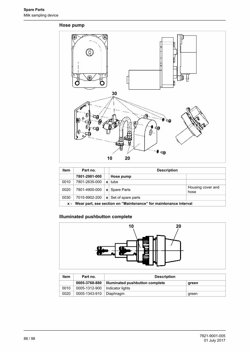
Spare Parts
Milk sampling device
7821-9001-00501 July 201788 / 98
Hose pump
10 20
30
Item Part no. Description
7801-2981-000 Hose pump
0010 7801-2635-000 x tube
0020 7801-4900-000 x Spare PartsHousing cover andhose
0030 7015-9902-200 x Set of spare parts
x - Wear part, see section on ”Maintenance” for maintenance interval
Illuminated pushbutton complete
10 20
Item Part no. Description
0005-3768-880 Illuminated pushbutton complete green
0010 0005-1312-900 Indicator lights
0020 0005-1343-910 Diaphragm green

Spare Parts
Bottle racks
7821-9001-00501 July 2017
89 / 98
Cable, complete
6030, 70 40
Item Part no. Description
7801-6933-010 Cable, complete Connection
0030 0005-1773-040 Connector housing HAN 3A-M20
0040 0005-4486-900 Cable Screw-Joint M16x1,5x5-10
0060 0005-4465-900 reduction M20x1,5 - M16x1,5
0070 0005-1773-030 Connector insert HAN 4A-M
10.2 Bottle racks
9000
Item Part no. Description
9000
7801-6451-000 Bottle rack DE / CH / JP / PL
7801-6451-010 Bottle rack NL (new) / USA
7801-6451-020 Bottle rack NL (old)
7801-6451-030 Bottle rack SE
7801-6451-040 Bottle rack DK
7801-6451-050 Bottle rack FR
7801-6451-060 Bottle rack LT / USA
7801-6451-070 Bottle rack NO
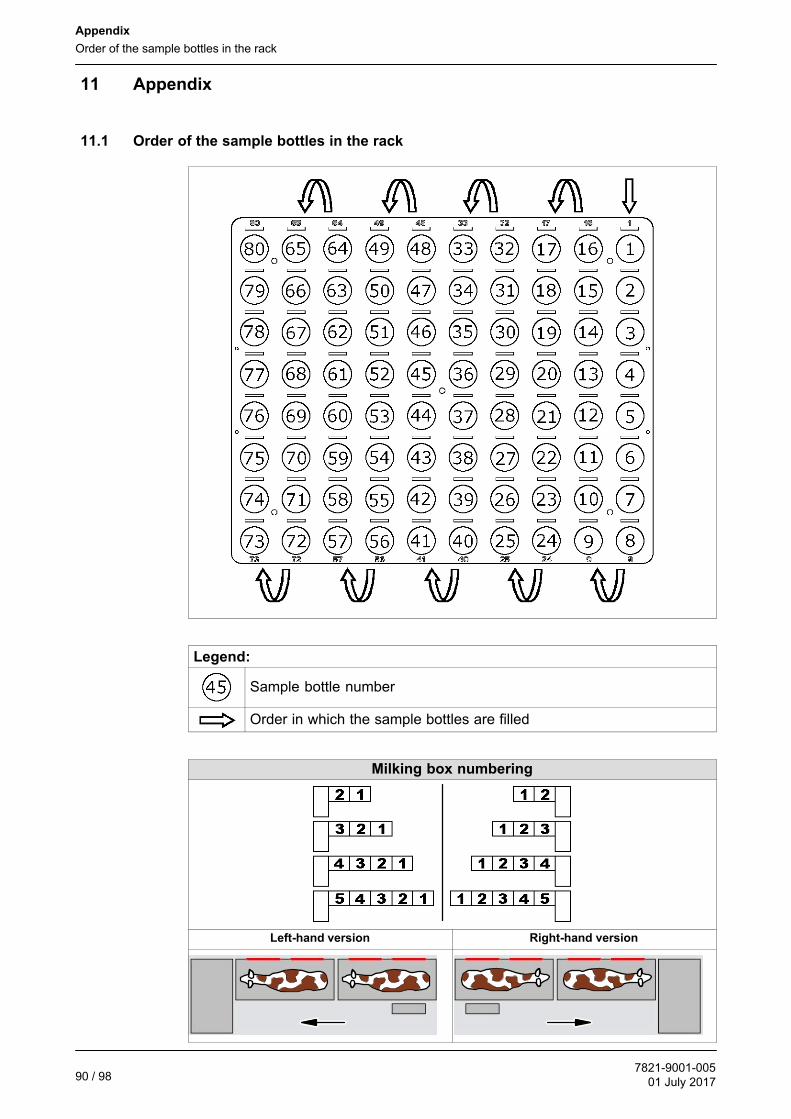
Appendix
Order of the sample bottles in the rack
7821-9001-00501 July 201790 / 98
11 Appendix
11.1 Order of the sample bottles in the rack
Legend:
Sample bottle number
Order in which the sample bottles are filled
Milking box numbering
Left-hand version Right-hand version

Appendix
Pin assignment
7821-9001-00501 July 2017
91 / 98
11.2 Terminal diagram for the CUP electronic card
7801-9047-030
1
2
3
4
Legend:
1 Valve
2 pump
3 Motor
4 Limit switch
11.3 Pin assignment
Legend:
UB 24V voltage monitoring (OUT)
SC Sample/Clean Signal (IN)
PE Earth, green/yellow (Protection Earth)
(1) Electrical Requirements
(2) dimensions
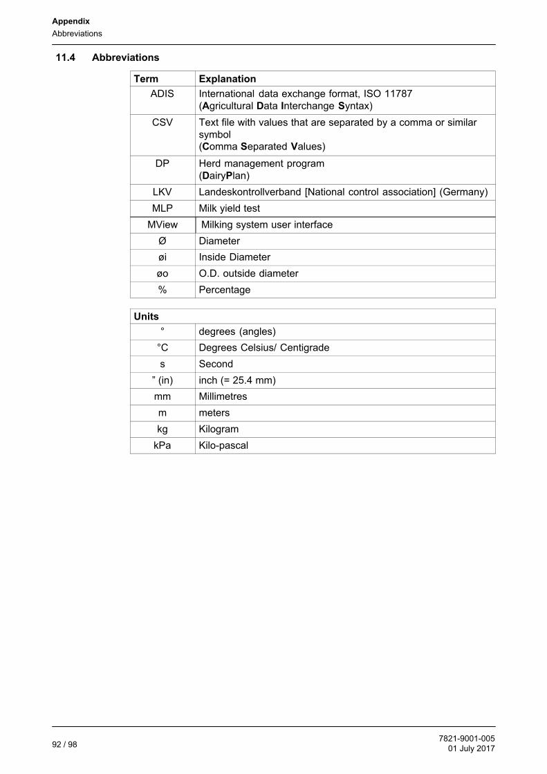
Appendix
Abbreviations
7821-9001-00501 July 201792 / 98
11.4 Abbreviations
Term Explanation
ADIS International data exchange format, ISO 11787(Agricultural Data Interchange Syntax)
CSV Text file with values that are separated by a comma or similarsymbol(Comma Separated Values)
DP Herd management program(DairyPlan)
LKV Landeskontrollverband [National control association] (Germany)
MLP Milk yield test
MView Milking system user interface
Ø Diameter
øi Inside Diameter
øo O.D. outside diameter
% Percentage
Units
° degrees (angles)
°C Degrees Celsius/ Centigrade
s Second
” (in) inch (= 25.4 mm)
mm Millimetres
m meters
kg Kilogram
kPa Kilo-pascal

Appendix
Quick guide
7821-9001-00501 July 2017
93 / 98
11.5 Quick guide
11.5.1 Start sampling
Stop automatic operation
● Open the menu item "Lock box"+++LOCK BOX
- Wait until the animals have left the milking boxes.
Set up and connect the sampling device
Set up the sampling device
● Place the bottle rack in the positioningdevice.

Appendix
Quick guide
7821-9001-00501 July 201794 / 98
Fit the sample tank in the milking system (Metatron)
● Connect the sampling tube on thesampling device to the sample tank.
Connect the cable to the automatic milking system
● Connect the 5-pole connector of thesampling case connection cable to theconnector of the monobox.
- The green indicator lamp on thesampling device will light.
● Press the "RESET" button.
- The filling nozzle will be heardmoving to the start position.

Appendix
Quick guide
7821-9001-00501 July 2017
95 / 98
Settings on the user interface of the automatic milking system
Starting sampling on the Mview.
● Enter the following settings:- Number of sample bottles per
bottle rack- Number of samples per animal- Boxes involved- Bottle rack number
- Enter the rack number
Starting sampling on the Mview.
● The following settings are possible:
Unlocking the milking box
● Open the menu item "Unlock box"+++UNLOCK BOX
Note the box data
Note the following data so that the data export can be checked:
● Sampling start time
● ID of the first cow in each box

Appendix
Quick guide
7821-9001-00501 July 201796 / 98
11.5.2 End of sampling
Stop automatic operation
Locking the milking box
● Open the menu item "Lock box"+++LOCK BOX
● Close entry gates to all milking boxes.- Wait until the animals have left the milking boxes.
Stop sampling
● Stop sampling
SAMPLING MODE (40 / 80)
Create the sample file
● Export sampling data.
For further information, see section"Sample data export".
Start the system clean
● Start system clean
Disconnect and remove the sampling device
● Carry out the steps described for setting up and connecting the device, but inreverse order.
Resume automatic operation
Unlocking the milking box
● Open the menu item "Unlock boxUNLOCK BOX

Appendix
Quick guide
7821-9001-00501 July 2017
97 / 98

Appendix
Quick guide
7821-9001-00501 July 201798 / 98
GEA Deutschland
GEA Farm Technologies GmbH
Siemensstraße 25-27 � +49 (0) 2383 / 93-70 [email protected]
D-59199 Bönen � +49 (0) 2383 / 93-80 gea.com
We live our values.
Excellence • Passion • Integrity • Responsibility • GEA-versity
GEA Group is a global engineering company with multi-billion euro sales and operations in more than 50countries. Founded in 1881, the company is one of the largest providers of innovative equipment and processtechnology. GEA Group is listed in the STOXX® Europe 600 index.