Embed Size (px)
Citation preview
Automatic guidance system for tractors in fruit farming
Martin Holpp1), Lorenz Dürr1)
1) Agroscope FAT Tänikon, Swiss Federal Research Station for Agricultural Economics and Engineering,
Tänikon CH-8356 Ettenhausen, Switzerland, Tel. +41 52 368 31 31, E-mail [email protected]
Introduction
Tractors frequently have to be steered in an exact straight line and along rows. This is
particularly applicable to fruit farming work, and requires a high degree of concentration
which often leaves no capacity for the checking of tractor-mounted implements and crops.
Automatic guidance systems reduce driver stress and allow more relaxed working and a
more efficient use of machines and resources.
GPS-based guidance systems have limitations when reception is poor or steering has to be
guided by the actual crop. This is the case in orchards, for example, where the trees and hail
protection netting interfere with reception. The plants then have to be scanned directly by
sensors and the tractor guided alongside. (Fig. 1)
Fig 1: left: apple orchard, right: berry orchard
For universal use, an automatic guidance system should be suitable for applications in fruit
farming, viticulture and arable farming, must be easy to retrofit and to move from one tractor
to another, and should have a reasonable cost-performance ratio.
Methods
In the initial development stage a control system was designed for fruit farming jobs and
mounted to an experimental tractor.
The components making up the control system are distance sensors, steering angle sensor,
steering drive, software controller and remote control.
Distance sensors
Fruit trees are planted in straight rows. Although the foliage is not uniform, the trunks make a
good guiding line for orientation. Some fruit tree trunks are only 2.5 cm in diameter and can
be about 0.5-2 m apart, depending on the type of fruit. At a driving speed of 7.2 km/h or 2
m/s, there is 12.5 ms in which to detect a tree. A DataSensor S80 rapid laser sensor (500 Hz
scanning frequency) with a wide range (up to 4 m) is used for detection. Several readings are
thus taken for each tree and the mean value is calculated.
Trunks cannot be scanned in berry orchards, but the foliage is uniform and makes a good
guiding line. Green leaves do not reflect enough red light from the laser sensor, so an
Baumer ultrasonic sensor UNDK50 (range 0.5-2.5 m) is used here.
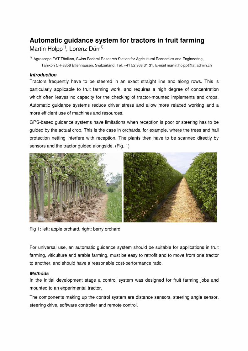
Both sensors are mounted to the front hydraulics of the tractor with powerful magnets and
can be used alternately. (Fig. 2, left)
Fig. 2: left: distance sensors (top: ultrasonic; bottom: laser), right: steering angle sensor
Steering angle sensor
Various sensors to determine the steering angle were tested. A rotary potentiometer
mechanically linked to the steering knuckle of the steering axle was unreliable in operation.
Alternatively, the steering angle could be determined using the stroke of the hydraulic
steering cylinder. The distance to a reflector plate at the piston end is measured by a sensor
on the cylinder and converted into the steering angle. The laser sensor used initially was
sensitive to sunlight and was exchanged for an Baumer UNDK20 ultrasonic sensor (range
60-400 mm). (Fig.2, right)

Steering drive
The aim was to make the steering drive as simple and uniform as possible and not to
interfere with the steering hydraulics.
This was realised by means of a motor via a wheel-and-disc drive acting directly on the
steering wheel. The drive is mounted to a hinged spring-steel rocker and can be swung out
of the way when not in use. (Fig. 3)
Fig 3: Steering drive: working position (left), turned off (right)
Steering control
Automatic control is assured by DASYlab control software via interface cards on a tablet PC
(Fig 4).
Fig 4 left: Tablet PC with interface box, right: Dasylab software
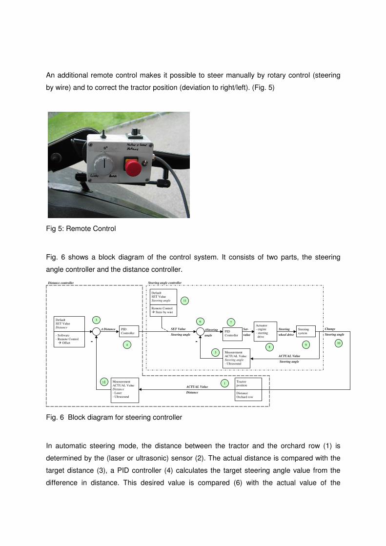
An additional remote control makes it possible to steer manually by rotary control (steering
by wire) and to correct the tractor position (deviation to right/left). (Fig. 5)
Fig 5: Remote Control
Fig. 6 shows a block diagram of the control system. It consists of two parts, the steering
angle controller and the distance controller.
Change
Steering angle
Steering
wheel drive
Set-
value
∆Steering
angle
SET Value
Steering angle
∆ Distance
Default SET Value
Distance
- Software
- Remote Control
� Offset
PID
Controller
Measurement
ACTUAL Value
Distance
- Laser
- Ultrasound
Actuator - engine
- steering
drive
Measurement
ACTUAL Value Steering angle
- Ultrasound
Steering
system
Tractor position
ACTUAL Value
Steering angle
ACTUAL Value
Distance
- -
PID
Controller
Remote Control
� Steer by wire
Default
SET Value
Steering angle
Steering angle controller
21
3 7 6
5
4
1
9 8
11
0
10
Distance
Orchard row
Distance controller
Fig. 6 Block diagram for steering controller
In automatic steering mode, the distance between the tractor and the orchard row (1) is
determined by the (laser or ultrasonic) sensor (2). The actual distance is compared with the
target distance (3), a PID controller (4) calculates the target steering angle value from the
difference in distance. This desired value is compared (6) with the actual value of the

steering angle (5), another PID controller (7) calculates the set value for the engine control
(8) on the basis of the difference in steering angle. The steering drive turns the steering
wheel (9), thus changing the steering angle (10) and the distance of the tractor from the
orchard row (1).
In manual steering mode, the distance controller is turned off and the desired steering angle
value is set and regulated directly by the remote control (11).
Results
Tree trunks of ≥2.5 cm in diameter and trees up to 1 m apart were reliably detected with the
laser sensor at a speed of up to 1.5 m/s. The tractor could be driven past foliage at up to 1.5
m/s with the ultrasonic sensor. The accuracy of the system was measured by a DataSensor
S80 laser sensor on the drawbar and was approx. +/- 10 cm. (Fig 7 & 8)
Fig 7 left: Measuring control accuracy with a laser sensor in a trial with wooden stakes,
right: laser sensor for distance control in the rear hydraulics
All the components can be moved quickly from one tractor to another, only the mountings are
permanently fixed to the vehicle.
The flexible design of the controller allows additional sensors such as GPS, mechanical
probes or camera systems to be fitted, and the range of application to be extended to other
crops.

Figure 8: Results of control accuracy with a laser sensor:
2 speed versions in 5 repetitions:
s02-s06=1 ms-1
; s09-s17=1.5 ms-1
; = wooden stakes
Conclusion
The system concept meets present-day requirements for an automatic guidance system.
Further development will focus on the optimisation of control algorithms and the integration of
further sensors. The aim is to support alternative mechanical measures for the control of
weeds such as rumex obtusifolius L. in grassland, and for hoeing in row crops and arable
crops.