Embed Size (px)
Citation preview

EUROGRAPHICS 2005 / M. Alexa and J. Marks(Guest Editors)
Volume 24 (2005), Number 3
Automatic Generation of Structure PreservingMultiresolution Models
Martin Marinov Leif Kobbelt
Computer Graphics Group, RWTH Aachen, Germany
AbstractWe are proposing a multiresolution representation which uses a subdivision surface as a smooth base surfacewith respect to which a high resolution mesh is defined by normal displacement. While this basic representation isquite straightforward, our actual contribution lies in the automatic generation of such a representation. Given ahigh resolution mesh, our algorithm is designed to derive a subdivision control mesh whose structure is properlyadjusted and aligned to the major geometric features. This implies that the control vertices of the subdivisionsurface not only control globally smooth deformations but in addition that these deformations are meaningful inthe sense that their support and shape correspond to the characteristic structure of the input mesh. This is achievedby using a new decimation scheme for general polygonal meshes (not just triangles) that is based on face merginginstead of edge collapsing. A face-based integral metric makes the decimation scheme very robust such that wecan obtain extremely coarse control meshes which in turn allow for deformations with large support.
Categories and Subject Descriptors (according to ACM CCS):I.3.5 [Computer Graphics]: Curve, surface, solid, and object representations. Modeling packages.
1. Introduction
Due to the availability of reasonably priced 3D scanningequipment the need for shape modeling techniques whichenable the flexible modification of (unstructured) high res-olution 3D models becomes more and more evident. Ide-ally such techniques should be independent from the actualtessellation of the mesh and they should provide handlesthrough which the user can control the shape in a flexibleand intuitive way. Due to the high complexity of the scannedmeshes, necessary for representing the edited model witha certain precision, multiresolution modeling techniques re-sort to a coarse, low frequency representation (base domain)of the input geometry, so that the designer can efficiently de-scribe the editing operations. Such an approach imposes arestriction on the used base-domain: it has to represent thestructure of the model as close as possible, so that a modifi-cation expressed with respect to it propagates in an intuitivefashion to the edited mesh.
On the other hand, the ability to simplify the base do-main such that just the very basic features of the object arepresent, allows large scale, almost global modifications to beperformed. In addition, such modeling framework has to be
flexible, permitting the designer to change the desired con-trol resolution at any point, i.e., it needs to be progressive.Finally, the automatic generation of such a representationis highly desirable, especially in a production environment,since the costs associated with a reverse engineering/rapidprototyping cycle depend mostly on the amount of manualwork (time) required. In this paper we propose a modelingframework in conjunction with a simplification algorithm,which conform to these requirements and provide an easy touse, flexible tool-set for editing polygonal meshes.
1.1. Contributions
Our first contribution is a new simplification scheme forpolygonal meshes (Section 2) which generates a progressivesequence of coarser versions of the input mesh M adjustedand aligned to the major geometric features. The algorithmis specifically designed to overcome difficulties arising whenM is decimated to extremely coarse resolutions and providesvalid, non-folding, two-manifold polygonal meshes approx-imating the structure of the model (Fig. 2). The schemeis guided by two major principles: minimizing the integralL2/L2,1 error for all faces (this provides the relation to theinput surface) and guaranteeing that each face is injectively
c© The Eurographics Association and Blackwell Publishing 2005. Published by BlackwellPublishing, 9600 Garsington Road, Oxford OX4 2DQ, UK and 350 Main Street, Malden,MA 02148, USA.

M. Marinov & L. Kobbelt / Automatic Generation of Structure Preserving Multiresolution Models
Figure 1: From left to right: a) A tessellated CAD model as input. b) The model simplified to 24 faces. c) A correspondingCatmull-Clark surface with 44 control points. d) Using c) as a base domain of our multiresolution model allows us to performseveral large-scale modifications on the original mesh (represented as a normal displacement field). Notice that moving acontrol point leads to a “meaningful” deformation because the coarse control mesh captures the global structure of the model.
projectable to a plane (this weakly controls the quality of in-dividual faces). As already observed in [CSAD04], the inte-gral L2/L2,1 metric leads to a very robust and faithful align-ment of the geometric clusters to the major anisotropic fea-tures of the surface. Even if we run a greedy procedure forthe simplification instead of a global Lloyd-relaxation, wecan still exploit the same effect and hence obtain polygonalmeshes which reliably capture the shape and structure of theinput geometry very well. The additional injectivity condi-tion prevents the polygonal faces (= clusters) from degener-ating while not affecting the alignment properties.
Next we propose an elegant two-scale framework (Section3), which allows for modeling of an arbitrary input meshby simply moving control points as in [ZSS97]. The low-frequency, base domain for performing the modification is asmooth (almost everywhere) C2 subdivision surface S (Fig.1). We take advantage of several properties of our simplifi-cation scheme, which is used to produce the control meshof the subdivision surface: Since the user is able to browsethe sequence of fine-to-coarse representations of M, a de-sired domain surface S is available at any level of detail.The control points are placed at intuitive locations and themesh faces are aligned with the anisotropy of the input sur-face, hence the support of the modification corresponding toa control point movement is naturally defined and adjustedwith the structure of the model. Also, refining the controlmesh is not constrained to a uniform refinement of a fixedbase domain, but is completely irregular and new degreesof freedom are placed adaptively in accordance to the em-ployed approximation metric. Since our simplification algo-rithm operates natively with general polygonal faces, bothCatmull-Clark [CC78] and Loop [Loo87] surfaces are sup-ported. We focus on the former because quad-dominant con-trol lattices are more relevant for CAD applications.
1.2. Related work
Simplification: Numerous techniques exist for simplifyingthe complexity of a polygonal mesh, most of them are guidedby a specific approximation metric, sometimes augmentedby a quality measure for the produced elements. Greedymesh decimation schemes, such as the one we present, are
among the most popular methods. Partitioning through a re-peated vertex collapsing was proposed by [SZL92, Hop96,GH97, KLS96]. The dual technique, face clustering, wasemployed for a high level description of the input geom-etry by [KT96, GWH01, LPRM02]. Face clustering in thecontext of mesh generation was specifically explored in[She01, CSAD04, BMRJ04]. A global optimization tech-nique for mesh simplification was proposed in [HDD∗93].
With the sole exception of [CSAD04, BMRJ04], all ofthese techniques target at triangle mesh generation. How-ever, quad-dominant meshes are required for producinghigh-quality Catmull-Clark subdivision surfaces. Moreover,none of them is able to produce extremely coarse artifact-free meshes required for global, structure aligned deforma-tions. Our simplification scheme is designed to overcomeexactly these issues: it produces extremely coarse, structure-preserving, polygonal and artifacts-free meshes.
Modeling: We restrict our survey of free-form modelingtechniques to approaches similar to ours, i.e., surface ori-ented methods. Direct polygonal mesh modeling was pro-posed by [WW94]. In [ZSS97], an input mesh is convertedto a multiresolution Loop surface and deformations are per-formed interactively by transforming degrees of freedomon different levels of detail. In [LLS01], an arbitrary meshis converted into a multiresolution Catmull-Clark surface,however, the user has to predefine the base control mesh. Torepresent the input mesh without resampling, these methodsemploy local frame encoding using multiple levels of detail.
In contrast to them, variational techniques for polygonalmesh modeling [KCVS98, BK04] use single level of detailto encode the fine scale geometry solely as normal displace-ments (without resampling). Our approach is positioned in-between these two paradigms: we use a subdivision sur-face to control the deformation, but a single fine scale isrepresented as normal displacements. However, unlike dis-placed subdivision surfaces [LMH00], we do not require re-sampling of the input geometry and hence avoid aliasingand other under-sampling artifacts. Recently, several alterna-tive ways for performing modeling operations on polygonalmeshes were proposed in [YZX∗04, SLCO∗04, LSCO∗04].
c© The Eurographics Association and Blackwell Publishing 2005.
M. Marinov & L. Kobbelt / Automatic Generation of Structure Preserving Multiresolution Models
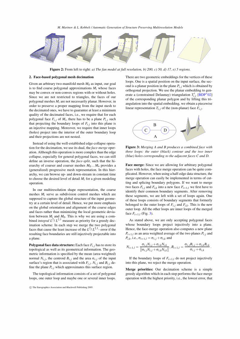
Figure 2: From left to right: a) The fan model at full resolution, b) 200, c) 50, d) 17, e) 5 regions.
2. Face-based polygonal mesh decimation
Given an arbitrary two-manifold mesh M0 as input, our goalis to find coarse polygonal approximations Mi whose facesmay be convex or non-convex regions with or without holes.Since we are not restricted to triangles, the faces of ourpolygonal meshes Mi are not necessarily planar. However, inorder to preserve a proper mapping from the input mesh tothe decimated ones, we have to guarantee at least a minimumquality of the decimated faces, i.e., we require that for eachpolygonal face Fi, j of Mi, there has to be a plane Pi, j suchthat projecting the boundary loops of Fi, j into this plane isan injective mapping. Moreover, we require that inner loops(holes) project into the interior of the outer boundary loopand their projections are not nested.
Instead of using the well-established edge-collapse opera-tion for the decimation, we use its dual, the face-merge oper-ation. Although this operation is more complex than the edgecollapse, especially for general polygonal faces, we can stilldefine an inverse operation, the face-split, such that the hi-erarchy of coarser and coarser meshes M0 ...Mn provides a(generalized) progressive mesh representation. In this hier-archy, we can browse up- and down-stream in constant timeto choose the desired level of detail Mi for a given modelingoperation.
In our multiresolution shape representation, the coarsemeshes Mi serve as subdivision control meshes which aresupposed to capture the global structure of the input geome-try at a certain level of detail. Hence, we put more emphasison the global orientation and alignment of the coarse edgesand faces rather than minimizing the local geometric devia-tion between Mi and M0. This is why we are using a com-bined integral L2/ L2,1 measure as priority for a greedy dec-imation scheme: In each step we merge the two polygonalfaces that cause the least increase of the L2/ L2,1- error if theresulting face boundaries are still injectively projectable intoa plane.
Polygonal face data structure: Each face Fi, j has to store itstopological as well as its geometrical information. The geo-metric information is specified by the mean (area-weighted)normal Ni, j , the centroid Bi, j and the area σi, j of the inputsurface’s region that is associated with Fi, j. Ni, j and Bi, j de-fine the plane Pi, j which approximates this surface region.
The topological information consists of a set of polygonalloops, one outer loop and maybe one or several inner loops.
There are two geometric embeddings for the vertices of theseloops. One is a spatial position on the input surface, the sec-ond is a planar position in the plane Pi, j which is obtained byorthogonal projection. We use the planar embedding to gen-erate a (constrained Delaunay) triangulation T ′
i, j [BDP∗02]of the corresponding planar polygon and by lifting this tri-angulation into the spatial embedding, we obtain a piecewiselinear representation Ti, j of the (non-planar) face Fi, j.
Figure 3: Merging A and B produces a combined face withthree loops: the outer (black) contour and the two inner(blue) holes corresponding to the adjacent faces C and D.
Face merge: Since we are allowing for arbitrary polygonalfaces with holes, the face merge operation can be quite com-plicated. However, when using a half-edge data structure, themerge operation can easily be implemented in terms of cut-ting and splicing boundary polygons. If we want to mergetwo faces Fi, j and Fi,k into a new face Fi+1,l we first have toidentify their common boundary segments. After removingthese segments, we are left with a set of loops again. Oneof these loops consists of boundary segments that formerlybelonged to the outer loops of Fi, j and Fi,k. This is the newouter loop. All the other loops are inner loops of the mergedface Fi+1,l (Fig. 3).
As stated above, we are only accepting polygonal faceswhose boundary loops project injectively into a plane.Hence, the face-merge operation also computes a new planePi+1,l as an area weighted average of the two planes Pi, j andPi,k, i.e., σi+1,l = σi, j + σi,k and
Ni+1,l =σi, jNi, j + σi,kNi,k
∥
∥σi, jNi, j + σi,kNi,k∥
∥
, Bi+1,l =σi, jBi, j + σi,kBi,k
σi, j + σi,k.
If the boundary loops of Fi+1,l do not project injectivelyinto this plane, we reject the merge operation.
Merge priorities: Our decimation scheme is a simplegreedy algorithm which in each step performs the face mergeoperation with the highest priority, i.e., the lowest error, that
c© The Eurographics Association and Blackwell Publishing 2005.

M. Marinov & L. Kobbelt / Automatic Generation of Structure Preserving Multiresolution Models
Figure 4: From left to right: a) A scanned (high genus) technical part. b) On a coarse level the complete right side is pusheddown and the left side is extended. c) Switching to a finer scale, we round a sharp corner using the additional controls.
does not violate the injectivity criterion. Each merge opera-tion is potentially followed by a number of valence two ver-tex removals. Then the priorities are updated and the nextmerge operation is selected.
Similarly to [CSAD04] we base our error measure on acombined integral L2/ L2,1- metric. In order to estimate itsvalue for a given (merged) face Fi+1,l , we integrate the L2
deviation of the lifted CDT Ti+1,l with respect to the proxyplane Pi+1,l : Let d0, d1, d2 be the distances from the verticesof a triangle t ∈ Ti, j ∪ Ti,k from the plane Pi+1,l . The integralL2 error of Pi+1,l with respect to t is:
L2(t,Pi+1,l) =16
(d20 + d2
1 + d22 + d0d1 + d0d2 + d1d2) |t|
as shown in [CSAD04]. Finally we estimate the total L2 errorfor the face Fi, j as:
L2(Fi+1,l) = ∑t∈Ti, j
L2(t,Pi+1,l)+ ∑t∈Ti,k
L2(t,Pi+1,l) .
The L2,1 deviation is estimated by computing an areaweighted sum of the deviation between the normals beforeand after the merge:
L2,1(Fi+1,l) = σi, j ·∥
∥Ni, j −Ni+1,l∥
∥
2+σi,k ·
∥
∥Ni,k −Ni+1,l∥
∥
2.
Notice that both error measures are only approximations tothe true errors with respect to the original input mesh M0.However, since the integral has a low-pass filtering effectanyway and since we never noticed a significant differencein the quality of the resulting coarse meshes Mi when usingthe true measure, we decided to use the approximate mea-sure which can be evaluated much more efficiently, in con-stant time.
Since a weighted sum of the two error measures is notscale independent, we rather combine the two measures bymultiplying them so that the L2,1 metric acts as a weightingfactor for the L2 metric and vice-versa:
E(Fi+1,l) =[
1 + L2(Fi+1,l)]
·[
1 + L2,1(Fi+1,l)]
. (1)
Contour decimation: The face-merge operation does notremove any vertices from Mi. Hence we need a second op-eration to actually reduce the geometrical complexity. In our
algorithm, this operation is simply removing the valence twovertices that appear after several faces have been merged(Fig 5).
Figure 5: To decimate the contours of the merged regions weremove all excess valence two vertices.
For closed meshes, we decimate every valence two vertexvk as soon as it appears. For meshes with boundary we haveto take some error measure into account in order to preservethe shape of the input surface’s boundary. As there is onlyone face incident to a boundary valence two vertex, we sim-ply compute the corresponding L2 error integral in closedform by
L2(vk) =13
∥
∥v j − vl∥
∥d2 ,
where v j and vl are the two adjacent vertices to vk and d isthe orthogonal distance of vk to the edge v jvl . The L2,1 errorvanishes because the face normal does not change after thevertex removal, hence E(vk) = 1 + L2(vk).
In any case, in order to prevent fold-overs in non-convexfaces or in faces with holes, we allow removing any vk onlyif the injectivity criterion is true for the adjacent faces afterthe removal. Moreover, in order to avoid inconsistencies inthe mesh Mi+1, the removal operator is permitted only if theedge (v j,vl) did not already exist in the mesh Mi.
Performance considerations: The most time consumingstep in the decimation procedure is the construction of theCDT Ti, j after every merge or removal operation. The Ti, j isnecessary to evaluate the approximate L2/L2,1 error mea-sures. The complexity of this step grows like O(m logm)with the valence m of the polygonal face Fi, j. This can leadto performance problems in flat surface regions where theerror measure (1) is very small and faces with very high va-lence can occur. In order to avoid these pathological config-urations, we add another criterion to the decimation schemewhich prefers low valence faces. However, this criterion hasto be designed in such a way that it does not influence the
c© The Eurographics Association and Blackwell Publishing 2005.

M. Marinov & L. Kobbelt / Automatic Generation of Structure Preserving Multiresolution Models
decimation scheme in regions where the error measure (1)has non-vanishing values.
Consequently, we add two more factors (1 + ε(m− 4)2)and (1 + ε ∑q(αq − π/2)2) with some small weight coeffi-cient ε to the combined error measure (1) where m is the facevalence and αq are the inner angles at the vertices incidentto the removed boundary segment(s) shared by Fi, j and Fi,k.These two factors penalize high valences and non-regularinner angles. However, due to the small weight coefficientε these factors can influence a greedy decision only if theother factors are close to constant and hence they act like a“tie-break”. Note that these penalty terms are not meant toenforce the quality of the mesh elements in general — weneed them only to prevent uncontrolled growth of the CDTscomputation time in regions where the input mesh is nearlyplanar.
3. Multiresolution modeling
Subdivision control mesh generation: Once the input meshM0 is simplified to the coarsest possible level Ml , the user isable to browse the resulting hierarchy and choose a level ofdetail (an intermediate mesh) Mi which we use to define thebase domain for subsequent modeling operations. We con-vert the selected Mi into a proper subdivision control meshLi defining a (limit) surface Si. For Catmull-Clark surfaces,we have to construct Li in a way that guarantees fair limitsurfaces. In particular this means that we have to avoid non-convex faces and faces with high valence and that we preferquad-dominant meshes. Since we do not want to insert addi-tional vertices, we have to find a convex partitioning withoutSteiner points for each face Fi, j. This partitioning has to beapplied to the planar embedding of Fi, j and is then liftedto its spatial embedding. The convex partitioning algorithmsavailable in the literature [HM83, KS98] do not provide therequired solution since they do not take the valence of thegenerated convex faces into account.
Suppose Γ is some convex partitioning of a polygonalface Fi, j. We define a score function ω for every cell f ∈ Γ:ω( f ) = 0 if val( f ) = 4, ω( f ) = 1 if val( f ) = 5, ω( f ) = 2if val( f ) = 3 and ω( f ) = ∞ otherwise. Valence 5 cells arepreferred due to the better quality of the subdivision limitsurface compared to valence 3 cells. The score of the com-plete partitioning Γ is defined as ω(Γ) = ∑ f∈Γ ω( f ).
We are interested in finding a partition Γ which minimizesω(Γ). The already computed CDT Ti, j of Fi, j exhibits angleoptimality with respect to the choice of available diagonalsin the planar embedding of Fi, j. Hence, similarly to [HM83]we restrict our convex partitioning to diagonals existing inTi, j . Since the number of vertices in Fi, j is usually small,a brute force approach with branch caching rapidly finds theoptimal Γ by simply checking all possible decompositions. IfFi, j happens to have higher valence than a certain threshold(20 vertices), we fix several diagonals from Ti, j in order to
split Fi, j into a few smaller polygons and run the brute-forcealgorithm on each of them.
Normal displacement: In order to represent the input meshM0 as a normal displacement of the subdivision limit sur-face Si, we need to find for every vertex vk ∈ M0 a foot-pointSi(tk) on the surface Si such that the displacement vectorvk − Si(tk) is orthogonal to the tangent plane of Si at Si(tk).Since there is no analytical solution to this problem, we firsthave to generate some initial estimate rk for tk and then itera-tively improve this estimate by an exact closest point searchon Si [MK04]. The convergence of the closest point searchdepends on the quality of the initial estimate rk. Hence, wegenerate these estimates by computing a global parameteri-zation of M0 which uses the subdivision control mesh Li as adomain. Notice that our conversion procedure from Mi to Liis based on a convex partitioning of the planar embedding ofeach face Fi, j. As a consequence, all we have to do is to mapthis partitioning back onto the input mesh M0 and then com-pute an individual parametrization for each of the resultingpatches (Fig. 7).
Figure 7: Left: The Rocker Arm model simplified to 5 re-gions. Middle: The global map corresponding to this resolu-tion (visualized as normal map). Right: The correspondingclusters.
More precisely: Since the decimated faces Fi, j have beengenerated by face-merging, there is a unique surface patchCi, j on M0 which is associated with Fi, j. In particular, theboundary of the patch Ci, j is associated with the planarembedding of the boundary of Fi, j. The diagonals used inthe convex partitioning of Fi, j can be mapped to shortestpaths (inside Ci, j) between the corresponding vertices of M0.These shortest paths are easily computed by Dijkstra’s algo-rithm. If several diagonals are adjacent to the same bound-ary vertex of Fi, j then we might have to locally refine M0in order to keep the shortest paths disjoint (Fig. 8). Afterwe have fixed the parameterization of all vertices of Ci, jmapped to the edges of the convex partitioning of the pa-rameter domain Γ, we setup a sparse linear system for eachcell to compute the parameterization of the remaining ver-tices using Floater’s mean value weights [Flo03]. Then forevery vk ∈ M0 we improve the initial parameter value rk by
c© The Eurographics Association and Blackwell Publishing 2005.

M. Marinov & L. Kobbelt / Automatic Generation of Structure Preserving Multiresolution Models
Figure 6: From left to right: a) The bunny model simplified to 14 regions. b) The corresponding control mesh and its first levelCatmull-Clark subdivision. c) Using b) large scale modifications are applied to the back and the head. d) A finer resolution (83regions) is selected. e) The new control vertices are used to alter the ears.
iteratively updating it towards the exact foot-point parametervalue tk [MK04].
Figure 8: Close-up view on a parameterization around thehole of the Rocker arm model. The map constraints are setupon the blue lines. Note the vertices (red points) refining M0so that disjoint vertex paths corresponding to the diagonalsof the domain partition are possible.
Two-scale model: We define the two-scale model Qi whichrepresents the vertex positions of the original input mesh M0as normal displacements Di with respect to Si. More pre-cisely, Qi is the collection of the following entities: the sub-division surface Si (base scale), the parameter values tk ofthe foot-points of the vertices of M0 on Si (parameteriza-tion) and the normal displacements dk such that
vk = Si(tk)+ dk ·Ni(ti) , (2)
where vk ∈M0 and Ni(tk) is the normal of Si at tk (fine scale).
Editing: By moving control vertices of the control mesh Li,the user deforms the two-scale model Qi in a region definedby the resolution of Li, i.e., in the region corresponding to thesupport of the respective subdivision basis functions. Sinceour decimation scheme produces structure-aligned meshesMi, the distribution of subdivision control vertices as well asthe shape of the corresponding basis function’s support arewell-adapted to the shape features of the underlying inputsurface. In this sense, our automatically generated multires-olution representation allows modifications which align tothe geometric structure of the input model M0.
Note that while initially the two-scale model Qi representsthe geometry of the of the input mesh M0, any subsequent
deformations are implicitly encoded by the (modified) posi-tions of the control points of Li. Hence, the deformed posi-tions of the fine scale vertices can be always computed byevaluating (2).
Resolution change: If another modification should be madeon a different scale, i.e., another level of detail M j is chosenby the designer, we first convert M j to a subdivision con-trol mesh L j as before. Since the current two-scale model Qimight have been deformed, we first propagate this deforma-tion on the new model Q j . To do that, we simply obtain thevertex positions of the fine scale vertices vk by evaluating(2). Note that since every control vertex of L j correspondsto a fine scale vertex (our decimation procedure is a sub-sampling process) the control vertices of L j are implicitlyshifted to their new (possibly deformed) positions. Accord-ingly the new normal displacements D j are computed withrespect to the new base surface S j (Fig. 4, 6).
4. Results
We tested our algorithm on various models, with empha-sis on CAD objects: Fig. 1, 2, 4. Recall that our simplifi-cation scheme discards the best possible merge operation interms of approximation error, if its result does not meet theminimum requirement of injective projection as specified inSection 2. Not surprisingly, this approach leads to a slightlysuboptimal approximation quality when compared to estab-lished methods such as [GH97] and [CSAD04]. However,we trade a small increase of the approximation error for thepossibility to generate much coarser meshes which are stillconsistent (Fig. 9).
In fact the initial prototype of our modeling frame-work used [CSAD04] to generate low complexity (control)meshes. However, since we did not find a way to produceunconditionally artifact-free meshes using this method, wedeveloped the presented simplification algorithm. We inten-tionally avoided dependence of any user-specified parame-ters, hence our decimation is fully automatic and not a “trialand error” experience. The decimation stops when there areno more possible valid simplification steps to be performed.
When compared to previous approaches, our modeling
c© The Eurographics Association and Blackwell Publishing 2005.

M. Marinov & L. Kobbelt / Automatic Generation of Structure Preserving Multiresolution Models
The fan model simplified to 36 triangles
The car model simplified to 92 triangles
Figure 9: From left to right: a) [GH97], b) [CSAD04], c) our result. The QEM decimationproduces acceptable meshes, but important features are smoothed out. On the other side theVSA meshes capture precisely the geometry structure, however at so coarse level of detail,exhibit artifacts and fold-overs. These issues can be resolved using more proxies, but at theexpense of additional triangles. Our algorithm preserves the structure of the original models,without introducing any artifacts, even on such low resolutions.
Figure 10: Michelangelo’sDavid simplified by ourmethod (395 vertices, 481convex faces, 235 quads).
framework exhibits several advantages. Switching to finerlevels in the hierarchy is not constrained to dyadic points asfor multiresolution subdivision surfaces [ZSS97]. Thereforeless degrees of freedom are necessary to control the surfacelocally, which in turn allows for more natural modificationsusing fewer controls (Fig. 11). Note that a dyadic refinementof a current (sub) set of control vertices is still straightfor-ward, in case one needs it at all. Also the support of the mod-ification is intuitive, since the control faces are adjusted tothe structure of the mesh. In addition, our framework is con-ceptually simpler since only plain subdivision surfaces areused, instead of the more complex multiresolution subdivi-sion surfaces [Zor97]. Compared to [LMH00], the advantageof our approach is that we do not have to re-sample the inputmesh and hence avoid alias artifacts. The supplemental videoprovided with the paper demonstrates editing operations onthe fan model and the car model using our framework.
Figure 11: From left to right: a) A scanned male head. b) Anintermediate base Catmull-Clark surface. c) The final resultafter several modifications. Note the new position of the leftear - it was moved by just translating a few control verticesof b). On a finer resolution, both of the ears were bended.
Beside modeling, the coarse meshes produced by our sim-plification technique can be exploited in a number of differ-ent applications, e.g., re-sampling and approximation. Forexample the control mesh on Fig. 6b has 25 vertices and23 faces (9 quads, 7 pentagons, 7 triangles) and still cap-tures the global shape of the bunny including the most prob-lematic region: its ears. The mesh subdivided once usingCatmull-Clark subdivision consists of 92 faces, all quads,i.e., its complexity is 60% of the coarsest control mesh ofthe bunny model presented in [BMRJ04]. On the other side,the finer control meshes which our method produces are notparticularly optimal with respect to the number of extraor-dinary control vertices. However, this was never a problemin practice, since for our purposes C1 continuity is fullysufficient. Also, with the availability of techniques improv-ing the surface smoothness in vicinity of extraordinary ver-tices [Loo04], this issue becomes less and less relevant forother applications as well.
Timings: For most models our simplification algorithm per-forms in-between the QEM simplification and the VSA ap-proach. Despite the greedy nature of the algorithm, the con-struction of a CDT in every simplification step increases thecomputation cost considerably. Our “prototype” implemen-tation takes about 3min for producing the simplification ofFig. 10, starting with a mesh consisting of 413K triangles.The simplification times for the Rocker Arm (80K faces),the car model (60K faces) and the fan model (13K faces) arerespectively 34sec, 26sec and 6sec. The computation timerequired for the parameterization of the input mesh on abase domain (including the normal displacement computa-tion) depends not only on the complexity of the input model,
c© The Eurographics Association and Blackwell Publishing 2005.

M. Marinov & L. Kobbelt / Automatic Generation of Structure Preserving Multiresolution Models
but also on the coarseness of the base mesh. Hence, it variesbetween several seconds for low complexity input meshes(4sec for the technical part in Fig. 4 — 18K faces) and a fewminutes for dense models parameterized over very coarsebase domains, e.g., 1min for the bunny (74K faces) over thedomain in Fig. 6b. Timing are taken on P4, 2.8GHz system.
5. Future work
One of the possible directions for improving our work iscombining a uniform and an irregular refinement [GKSS02]to build automatically a hierarchy which more closely con-forms to the standard for a CAD model, i.e., large regularpatches cover feature-less regions of the surface. Anotherinteresting route is topology removal. In fact, by introduc-ing an additional operator, our decimation is able to reducethe input topology in certain cases, however for now we didnot investigate that direction any further.
References
[BDP∗02] BOISSONNAT J.-D., DEVILLERS O., PION S., TEIL-LAUD M., YVINEC M.: Triangulations in CGAL. Comput.Geom. Theory Appl. 22 (2002), 5–19.
[BK04] BOTSCH M., KOBBELT L.: An intuitive framework forreal-time freeform modeling. ACM Transactions on Graphics 23,3 (Aug. 2004), 630–634.
[BMRJ04] BOIER-MARTIN I., RUSHMEIER H., JIN J.: Parame-terization of triangle meshes over quadrilateral domains. In Proc.of the Symposium on Geometry Processing (2004).
[CC78] CATMULL E., CLARK J.: Recursively generated B-splinesurfaces on arbitrary topological meshes. Computer Aided Geo-metric Design 10, 6 (Sep 1978), 350–355.
[CSAD04] COHEN-STEINER D., ALLIEZ P., DESBRUN M.:Variational shape approximation. ACM Transactions on Graph-ics 23, 3 (Aug. 2004), 905–914.
[Flo03] FLOATER M. S.: Mean value coordinates. ComputerAided Geometric Design 20, 1 (Mar. 2003), 19–27.
[GH97] GARLAND M., HECKBERT P. S.: Surface simplificationusing quadric error metrics. In Proc. of SIGGRAPH 97 (Aug.1997), pp. 209–216.
[GKSS02] GUSKOV I., KHODAKOVSKY A., SCHRÖDER P.,SWELDENS W.: Hybrid meshes: multiresolution using regularand irregular refinement. In Proc. of the Symposium on Comput.Geometry (2002), pp. 264–272.
[GWH01] GARLAND M., WILLMOTT A., HECKBERT P. S.: Hi-erarchical face clustering on polygonal surfaces. In 2001 ACMSymposium on Interactive 3D Graphics (Mar. 2001), pp. 49–58.
[HDD∗93] HOPPE H., DEROSE T., DUCHAMP T., MCDONALD
J., STUETZLE W.: Mesh optimization. In Proc. of SIGGRAPH93 (Aug. 1993), pp. 19–26.
[HM83] HERTEL S., MEHLHORN K.: Fast triangulation of sim-ple polygons. In Proc. of the FCT-Conference on Fundamentalsof Computation Theory (1983), pp. 207–218.
[Hop96] HOPPE H.: Progressive meshes. In Proc. of SIGGRAPH96 (Aug. 1996), pp. 99–108.
[KCVS98] KOBBELT L., CAMPAGNA S., VORSATZ J., SEIDEL
H.-P.: Interactive multi-resolution modeling on arbitrary meshes.In Proc. of SIGGRAPH 98 (July 1998), pp. 105–114.
[KLS96] KLEIN R., LIEBICH G., STRASSER W.: Mesh reduc-tion with error control. In IEEE Visualization ’96 (Oct. 1996),pp. 311–318.
[KS98] KEIL M., SNOEYINK J.: On the time bound for convexdecomposition of simple polygons. In Proc. of the CanadianConference on Comput. Geometry (1998).
[KT96] KALVIN A. D., TAYLOR R. H.: Superfaces: Polygonalmesh simplification with bounded error. IEEE Comput. Graph.Appl. 16, 3 (1996), 64–77.
[LLS01] LITKE N., LEVIN A., SCHRÖDER P.: Fitting subdi-vision surfaces. In IEEE Visualization 2001 (October 2001),pp. 319–324.
[LMH00] LEE A., MORETON H., HOPPE H.: Displaced subdi-vision surfaces. In Proc. of SIGGRAPH 00 (2000), pp. 85–94.
[Loo87] LOOP C.: Smooth subdivision surfaces based on trian-gles. Master’s thesis, University of Utah, 1987.
[Loo04] LOOP C.: Second order smoothness over extraordinaryvertices. In Proc. of the Symposium on Geometry Processing(2004).
[LPRM02] LÉVY B., PETITJEAN S., RAY N., MAILLOT J.:Least squares conformal maps for automatic texture atlas gen-eration. ACM Transactions on Graphics 21, 3 (July 2002), 362–371.
[LSCO∗04] LIPMAN Y., SORKINE O., COHEN-OR D., LEVIN
D., RÖSSL C., SEIDEL H.-P.: Differential coordinates for inter-active mesh editing. In Proc. of Shape Modeling International(2004), pp. 181–190.
[MK04] MARINOV M., KOBBELT L.: Optimization techniquesfor approximation with subdivision surfaces. In ACM Symposiumon Solid Modeling and Applications (2004), pp. 113–122.
[She01] SHEFFER A.: Model simplification for meshing usingface clustering. Computer Aided Design 33 (2001), 925–934.
[SLCO∗04] SORKINE O., LIPMAN Y., COHEN-OR D., ALEXA
M., RÖSSL C., SEIDEL H.-P.: Laplacian surface editing. InProc. of the Symposium on Geometry processing (2004), pp. 179–188.
[SZL92] SCHROEDER W. J., ZARGE J. A., LORENSEN W. E.:Decimation of triangle meshes. In Proc. of SIGGRAPH 92 (July1992), vol. 26, pp. 65–70.
[WW94] WELCH W., WITKIN A.: Free-form shape design usingtriangulated surfaces. In Proc. of SIGGRAPH 94 (July 1994),pp. 247–256.
[YZX∗04] YU Y., ZHOU K., XU D., SHI X., BAO H., GUO B.,SHUM H.-Y.: Mesh editing with poisson-based gradient fieldmanipulation. ACM Transactions on Graphics 23, 3 (Aug. 2004),644–651.
[Zor97] ZORIN D.: Subdivision and Multiresolution Surface Rep-resentations. PhD thesis, Caltech, Pasadena, California, 1997.
[ZSS97] ZORIN D., SCHRÖDER P., SWELDENS W.: Interactivemultiresolution mesh editing. In Proc. of SIGGRAPH 97 (Aug.1997), pp. 259–268.
c© The Eurographics Association and Blackwell Publishing 2005.