Embed Size (px)
Citation preview

Automatic generation of control sequences for manufacturing systemsbased on partial order planning techniques
L. Castillo* , J. Fdez-Olivares, A. Gonza´lez
Departamento de Ciencias de la Computacio´n e Inteligencia Artificial, E.T.S. Ingenierı´a Informatica, Universidad de Granada, 18071 Granada, Spain
Received 20 April 1998; received in revised form 25 July 1999; accepted 5 August 1999
Abstract
This work presents an approach for the application of artificial intelligence planning techniques to the automatic generation of controlsequences for manufacturing systems. These systems have some special features that must be considered in the planning process, but thereare difficulties when the usual models of action are used to deal with these features. In this work, a specialized interval-based model of actionis defined by extending the classic model ofstrips giving it more expressiveness so that it is able to deal with these features. In consequence,a specialized planning algorithm for this model of action, calledmachine, is defined based on a general partial order planning scheme, and itis able to obtain control sequences for manufacturing systems. These control sequences are actually the control program skeleton and may beeasily translated into real control programs expressed as GRAFCET charts.q 2000 Elsevier Science Ltd. All rights reserved.
Keywords: Partial order AI planning; Model of action; Manufacturing systems; Sequential control program
1. Introduction
One of the most appealing aspects of artificial intelli-gence planning techniques [1–4] is the strong similarityboth between the process of planning and the one ofprogramming and between the concept of plan and theone of algorithm. Although there was significant interestand work carried out in the beginning under the generaltopic of automated program synthesis [5–7] very littleadvance seems to have been produced since then. Perhapsthe problem of the automatic building of programs is toodifficult to be faced from a general viewpoint and researchshould have been focused on more specific domains.
In this sense, the domain of manufacturing systems isbecoming an area of growing interest for researchers fromthe field of artificial intelligence planning systems providinga more constrained domain of study. The design of thesequential control program for a manufacturing system isa difficult task which is traditionally carried out byengineers, but artificial intelligence planning techniquesare proving to be very useful [8,9], allowing for an error-free, fast and low-cost building process of these controlprograms. Furthermore, a new area of study called process
planning [10–12] has emerged from the application ofplanning techniques to machining procedures.
The advantages of such systems are clear. First of all,whenever the knowledge used by these systems is guaran-teed to be correct, the use of planning techniques would alsoguarantee that final plans are also correct and free ofmistakes or harmful interactions. Secondly, the time takento obtain plans would always be lower than the time taken toobtain the control program by hand, so these systems wouldachieve a considerable saving of engineering time. And inthird place, if, for some reason, the manufacturing systemchanges, then, instead of modifying the control program byhand, increasing the probability of introducing mistakes, thecontrol program would be completely rewritten taken intoaccount the new changes in a completely new controlprogram.
However, the results obtained are not as realistic as onecould expect because either the plan obtained does not havethe necessary level of detail, that is, there are actions whichare essential for the execution of the control program andthey are missing, or the plan is only focused in a small partof the overall manufacturing system.
The goal of this work is twofold, on the one hand, thedesign of a planning system which obtains plans at a suffi-ciently low level of detail so that it can be considered as acontrol program which will be called a control sequence. Acontrol sequence is an intermediate representation mechan-ism used by the planning system, but it contains the
Artificial Intelligence in Engineering 14 (2000) 15–30
0954-1810/00/$ - see front matterq 2000 Elsevier Science Ltd. All rights reserved.PII: S0954-1810(99)00025-4
www.elsevier.com/locate/aieng
* Corresponding author. Tel.:134-958-24-4019; fax:134-958-24-3317.E-mail addresses:[email protected] (L. Castillo), faro@decsai.
ugr.es (J. Fdez-Olivares), [email protected] (A. Gonza´lez).

necessary knowledge such that it can be easily translatedinto a sequential control program expressed as a GRAFCETchart [13] or a lower representation as a Petri net [14]. Onthe other hand, to extend these plans to the whole of amanufacturing system, including both transport and trans-formation operations, in order to obtain more realistic andcomplete plans, closer to what an engineer would call thecontrol program for a manufacturing system.
It is known that classic planning systems lack the neces-sary expressivity to solve real world problems and that thissubject has been widely studied [15–18]. However, thereare some features of manufacturing systems, which are diffi-cult to deal with even when using these models of action.Therefore, a specialized model of action, which is explainedin detail in Ref. [19] and, in consequence, a specializedplanning scheme, will be presented which takes thesefeatures into account in order to obtain more realisticresults.
This work is structured as follows. In Section 2, thesespecial features and their motivation are presented. Thenext sections are devoted to explaining how both the basicmodel of action ofstrips [20] and a general partial orderplanning scheme [21] may be extended in order to deal withthese features, configuring a specialized planning schemecalledmachine. The last sections show some experimentalresults and how some other interesting features should beincluded in this planning scheme.
2. Description of manufacturing systems
A manufacturing system is the set of processes, machinesand factories where raw products are transformed intohigher value manufactured products. Fig. 1 shows a toymanufacturing system, which will be used to introduce theproblem. It is composed of two tanks, a heater, a mixer, twovalves and a pump.
These transformations are carried out by the devices ofthe manufacturing system. The devices in Fig. 1 are theheater, the mixer, the valves and the pump. The operation
of every device is defined by a finite state automata wherethe states of the automata represent all the conditions inwhich the device is intended to be, and every transitionfrom one state to another represents an action of the device.For example, the automata, which describe the operation ofValve2 in Fig. 1, would be the one shown in Fig. 2. Hence,every action of every device implies both a transformationin the manufacturing system and a change of state in thedevice.
There are many representations for a control program fora manufacturing system like, for example, GRAFCET,Ladder or Petri nets [13,14], but for our purposes, the neces-sary level of detail to describe a control program is a controlsequence. A control sequence is an ordered sequence ofactions, i.e. a precedence graph, with all of the actions ofdevices needed to transform raw products into manufac-tured ones. The knowledge embedded in a control sequenceis sufficient to reason about the behavior of a controlprogram, therefore, aforementioned representations maybe considered as lower level representations or extensionsof a control sequence.1 For example, a possible controlsequence to heat and carry the water fromTank1 toTank2 could be like the one shown in Fig. 3.
Apparently, a sequence of actions like this could havebeen generated by any of the state of the art planners,however it has some interesting features that makes it diffi-cult to obtain mainly due to some inherent features of manu-facturing domains which must be taken into account. Let ussee these features.
2.1. Actions as intervals
Every action of every device executes as usual, but it issomehowactive, that is, it will maintain its effects, until thenext change of state in the automata of the device. Forexample, let us consider the actionTurnOn-Mixer . It isexecuted in the sequence and the water will becomeagitated, but it will be active until the execution ofTurn-Off-Mixer . Therefore, it seems reasonable to consideractions as intervals instead of as isolated points in thesequence, as in classical planners. This is the interval inwhich the action maintains its effects and it is consideredto be active. Some of these effects will disappear after thisinterval and others will remain. We will call this interval itsinterval of execution. For example, the interval of executionfor the action TurnOn-Mixer would be [TurnOn–Mixer , TurnOff–Mixer ].
There are many approaches in the literature that consideractions as intervals, for example, Refs. [15,18,22,23]. Insome of them, the end of this interval is defined by theachievement of all of its effects and in the others the endof the interval has an implicit relation with the action itself(for example, a known duration). However, none of these
L. Castillo et al. / Artificial Intelligence in Engineering 14 (2000) 15–3016
Fig. 1. A simple manufacturing system.
Fig. 2. The automata which describes the operation ofValve2 .

conceptions adequately fit in this problem. For example, letus consider the action of openingValve1 . It achieves itseffects at some point before the starting ofPump and itcontinues active until the shutting ofValve1 , later in thesequence, that is its interval of execution is [Open–Valve1 , Shut–Valve1 ]. This shows that the intervalof an action is neither defined by the achievement of itseffects (it is later) nor has a fixed relation with it, but thatit is active while there is no change of state in the device,that is, until the execution of another action that produces achange of state. If such an action does not exist, then theaction will continue active until the end of the sequence.
This is an important feature of the devices in a manufac-turing system. One can plan the execution of an action andthe action will execute, but it will continue active, and itseffects maintained, if no change of state is produced. If theend of the interval of execution of an action depends on theexecution of another action then, it depends on the processof planning itself, that is, the end of the interval will havealso to be planned.
2.2. Requirements during the actions
The second one, and very much related to the former, isthat, if actions are to be considered as intervals instead of aspoints, then the requirements which must hold in order toguarantee a correct execution of an action should also takeinto account this interval. That is, in addition to classicalpreconditions, as conditions which must holdbefore theaction, it is necessary to define some kind ofsimultaneousrequirementsas conditions which must holdduring theinterval of execution of the action. These requirements area form of theduringrelation in Ref. [15]. For example, let usconsider the actionTurnOn-Pump . It requires the valvesto be open before the pumping starts, but it is also necessaryfor them to remain open until the end of pumping, that is,during the interval of execution defined as [TurnOn–Pump, TurnOff–Pump ]. This kind of requirement isalso present in the literature. Simultaneous requirementsalso appear in Ref. [18] and later in an application byKlein et al. [24], but the difference here is that the intervalwhich defines the protection for thesesimultaneous require-mentsdoes not end with the achievement of the effects of theaction, but rather while the action is active, that is until
the next change of state produced by the execution ofanother action.
If actions are not considered as explained above, it isdifficult to guarantee that valves should be openduringthe interval of execution of the pump, that is, in the interval[TurnOn-Pump , TurnOff-Pump ], or that the watershould be in agitation during the heating of the water orthat Valve1 should be closed during the agitation of thewater.
2.3. Safe states
Finally, if one thinks about the example from a causalviewpoint, then a strictly correct sequence would have alsobeen the one shown in Fig. 4 because there is nothing thattells the devices to be off once the water is hot and it is inTank2 .
However, the truth is that there aresafe statesin theautomata which describe the operation of devices and thatthese states must be reached by every device before the endof the sequence. Actions needed to reach these safe statesare essential for the execution of the control sequence andthey are missing in the sequence in Fig. 4, so the correctsequence is actually the one shown in Fig. 3. One way tointroduce this feature in the process for the building ofsequences could just be by including these safe states inthe goal of the problem. Although this achieves a safestate for every device it seems too global, that is, it maybe difficult to decide the point in the sequence in which thedevice reaches a safe state, or even if it would be necessaryto use the same device later in the sequence and return it to asafe state. It seems that this decision is specific to eachaction that does not leave it in a safe state. Therefore, theneed to leave the device in a safe state can be modeled as alater requirement of some actions, that is, as a condition thatmust holdafter the action. In the example of the valve, thesafe state is the one in which the valve remains shut, so theneed to shut it as soon as possible could be modeled like alater requirement of the action which opens the valve.
In summary, these are the basic features which must betaken into account in order to reason about the actions thattake place in a manufacturing system, and in consequence,to obtain sequences like the one shown in Fig. 3. Basically,actions are considered as intervals in which they maintain
L. Castillo et al. / Artificial Intelligence in Engineering 14 (2000) 15–30 17
Fig. 3. A small control sequence.
Fig. 4. An alternative control sequence.

their effects. As seen before, considering actions as intervalsinstead of as points is not a new feature. However, the end ofthese intervals comes from the execution of another actionand, in consequence, it depends on the process of planningitself, or in other words, the end of the intervals of theactions must also be planned. In addition to this, newtypes of requirements are needed in order to both adequatelyguarantee this interval and to leave devices in a safe statebefore the end of a sequence.
These are very distinguishing features which do not fitadequately either into known models of action whichconsider actions as a point in a sequence, or in otherswhich consider actions as intervals, making the sequencein Fig. 3 very difficult to obtain. Therefore, the followingmodel for actions and plans has been defined.
3. A model for actions and plans
The model of action needed to deal with the previousfeatures may be obtained by extending the basic model ofstrips [20] in order to give devices a higher importance andto allow for the new types of requirements. A more detaileddescription of this model of action may be found in Ref.[19].
Every device in a manufacturing system is represented asanagentwhose operation is described by a finite state auto-mata. Thus, every agent has aset of statesE, which describeall the possible conditions in which it is intended to be, and aset of actionsA, each of which describes a transformationas well as a change of state in the agent. Additionally, anagent has a nameN, which must be unique,a set of vari-ablesV, which are used to represent the objects related tothe operation of the agent (like for instance products, chemi-cals, interconnection points between agents or constants)anda set of codesignation constraintsC defined on the setof variables, which define the set of valid values for everyvariable.
Agent� kN;E;V;C;Al
Everyactionof every agent is defined by a uniquenameN, a set of effects, which is represented by means of anaddition listADD, and adeletion listDEL of literals thatrepresent the transformation made by the action, and a set ofrequirements, divided into a list ofprevious requirementsANT, that must hold before the action, a list ofsimulta-neous requirementsDUR which must hold during the inter-val of execution of the action and a list oflater requirementsPOST, that must hold after the action.
Action� kN;ADD;DEL;ANT;DUR;POSTl
Example 1. This example roughly shows howValve2seen previously could be described by this model (using aLisp-based notation).
(AGENT(N Valve2)(E OPEN SHUT)(V ?SOURCE ?IN ?OUT ?CHEM)(C (?SOURCE NIL) (?IN (PUMP)) (?OUT(TANK2)) (?CHEM NIL))(A
(ACTION (N Open-Valve2)(ADD (STATE Valve2 OPEN) (OPEN-FLOW ?CHEM ?SOURCE ?OUT))(DEL (STATE Valve2 SHUT))(ANT (STATE Valve2 SHUT)(OPEN-FLOW ?CHEM ?SOURCE ?IN)(CONTAINS?CHEM ?SOURCE))(DUR (OPEN-FLOW ?CHEM ?SOURCE?IN))(POST (STATE Valve2 SHUT)))
(ACTION (N Shut-Valve2)…))
)
As may be seen, the interval of execution of an action ofan agent does not need to be included in its definitionbecause it does not depend on the action itself but on thedecision to include another action of the same agent thatchanges the state reached by the former action. Actually, theinterval of execution of an action is defined during the build-ing process of the sequence.
The description of the problems that appear in a manu-facturing system consists of a set of transformations, whichmust be made on raw products in order to obtain the manu-factured ones. Although most of the manufacturingprocesses are quite complex, in this paper only simple trans-formations are considered; however, they are expressiveenough to show the main difficulties during the buildingprocess of a control sequence. Thus, a problemP �kD;I;Gl is defined by the following components.
Domain. A domainD is a knowledge-based model of themanufacturing system and it is divided into a set ofagents, which represents the set of devices, their opera-tion and their interconnections described by this model ofaction, and a set of axioms, which describe facts whichare always true.Initial . The initial stateI is a conjunction of literals,which describe the initial state of both the manufacturingsystem and the raw products.Goal. A goalG is a conjunction of literals, which describethe transformation, needed to obtain manufacturedproducts from raw ones.
3.1. Plans
The solution to these problems consists in an ordered
L. Castillo et al. / Artificial Intelligence in Engineering 14 (2000) 15–3018

sequence of actions of the agents of the domain, whichachieves the goal starting from the specified initial state.This can be called a control sequence or an operationprocedure [25], but in this paper, it will also be called a plan.
Example 2. Let us consider the manufacturing systemshown in Fig. 5.
The set of agents and their actions are shown in Table 1.For example, the agent calledPUMP2is a pump, and it maybe either connected with the actionONPUMP2or discon-nected with the actionOFFPUMP2. The set of actions of thevalves has been abbreviated.
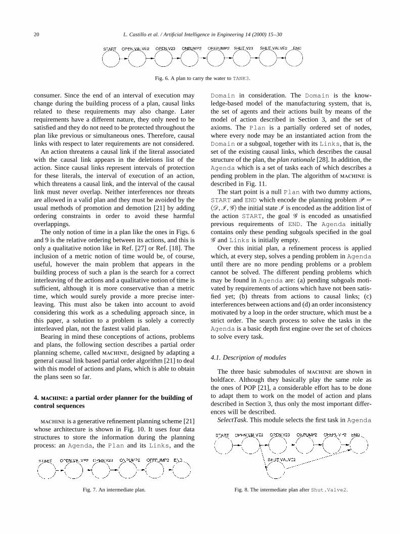
Let us suppose that the initial state shows the valvesclosed, and the pumps off. Then, Fig. 6 shows a plan tocarry the water toTANK3, where START and END aretwo dummy actions defined with the same meaning as inSNLP [26] or UCPOP [21].
This is only a structural description of what we consider aplan, the following explains in detail the semantics behindthis conception of plan.
3.2. The semantics of plans
Actions have an interval of execution, but this interval isdefined between every two consecutive actions in the planof the same agent, thus it may change during the buildingprocess of the plan as actions are included in the plan. Let usconsider the plan shown in Fig. 7 as an intermediate stepduring the building process of the overall plan forExample 2.
One may see that the actionOpen.Valve2 willexecute beforeOpen.V23 , but it will continue active
until the end of the plan. Thus, its interval of executionis [Open.Valve2 , END]. Now let us consider that theaction Shut.Valve2 is included in the plan obtainingthe plan as shown in Fig. 8.
This action produces a change of state inValve2 thataffect the state reached byOpen.Valve2 , so the intervalof execution for Open.Valve2 is revised and rede-fined as [Open.Valve2 , Shut.Valve2 ]. At once,the interval of execution ofShut.Valve2 appearsas [Shut.Valve2 , END].
Although actions have an interval of execution, this inter-val is not previously defined by the action itself but itdepends on the building process of a plan. This featurewill be very important during the building process of theplan.
Concurrent execution of several actions is somethingnatural in manufacturing systems and it is straightforwardlymodeled in the plan. Actions whose intervals of executionoverlap are concurrently executing. Let us consider thesequence in Fig. 6: the intervals of execution ofOpen.Valve2 , Open.V23 andOnPump2overlap. Thismeans that there is a moment (just beforeOffPump2 ) inwhich the three actions are executing concurrently, that is,the three actions are simultaneously active.
Although the examples seen so far show a total order ofactions, plans can have a partial order structure. A partialorder is used not only as a least commitment strategy torepresent a class of total order plans, but also to representpossible concurrency. For example, let us consider again themanufacturing system shown in Fig. 5. A plan to carryACID from TANK1 to TANK4 and WATERfrom TANK2to TANK3could be the one shown in Fig. 9. The fact thatboth branches of the program are unordered means thatthere is no commitment between them and, therefore, theintervals of execution of actions in both branches couldpossibly overlap, that is, they could possibly executeconcurrently.
An immediate consequence of the possibility of con-current execution of actions is that if the intervals of twoactions can possibly overlap, then both actions should notinterfere, that is, they must not have any opposite effect.This will be called aninterference.
Causal links[21,26] are also considered in the plan. Theydefine intervals of protection for the literals that appear inthe requirements lists of an action, which have beenpreviously solved by another action. The actions whichthese literals belong to are calledconsumersand the actionswhich solve them are calledproducers(in terms of Ref.[21]). Since there are three lists of requirements of differentnature, the interval which defines a causal link can differdepending on the type of requirement. The causal link asso-ciated with a previous requirement is defined from theproducer of the literal until the consumer. When the require-ment is a simultaneous one, then the causal link must bedefined during the entire execution interval of the action,that is, from the producer until the end of the interval of the
L. Castillo et al. / Artificial Intelligence in Engineering 14 (2000) 15–30 19
Fig. 5. An alternative manufacturing system.
Table 1The set of agents in Fig. 5
Type of device Agents Actions
Pumps PUMP1 ONPUMP1, OFFPUMP1PUMP2 ONPUMP2, OFFPUMP2
Valves Valve1 , V13, V14Valve2 , V23, V24
Open.Valve1 , Shut.Valve1 ,Open.V13 , etc.
consumer. Since the end of an interval of execution maychange during the building process of a plan, causal linksrelated to these requirements may also change. Laterrequirements have a different nature, they only need to besatisfied and they do not need to be protected throughout theplan like previous or simultaneous ones. Therefore, causallinks with respect to later requirements are not considered.
An action threatens a causal link if the literal associatedwith the causal link appears in the deletions list of theaction. Since causal links represent intervals of protectionfor these literals, the interval of execution of an action,which threatens a causal link, and the interval of the causallink must never overlap. Neither interferences nor threatsare allowed in a valid plan and they must be avoided by theusual methods of promotion and demotion [21] by addingordering constraints in order to avoid these harmfuloverlappings.
The only notion of time in a plan like the ones in Figs. 6and 9 is the relative ordering between its actions, and this isonly a qualitative notion like in Ref. [27] or Ref. [18]. Theinclusion of a metric notion of time would be, of course,useful, however the main problem that appears in thebuilding process of such a plan is the search for a correctinterleaving of the actions and a qualitative notion of time issufficient, although it is more conservative than a metrictime, which would surely provide a more precise inter-leaving. This must also be taken into account to avoidconsidering this work as a scheduling approach since, inthis paper, a solution to a problem is solely a correctlyinterleaved plan, not the fastest valid plan.
Bearing in mind these conceptions of actions, problemsand plans, the following section describes a partial orderplanning scheme, calledmachine, designed by adapting ageneral causal link based partial order algorithm [21] to dealwith this model of actions and plans, which is able to obtainthe plans seen so far.
4. machinemachine: a partial order planner for the building ofcontrol sequences
machine is a generative refinement planning scheme [21]whose architecture is shown in Fig. 10. It uses four datastructures to store the information during the planningprocess: anAgenda , the Plan and its Links , and the
Domain in consideration. TheDomain is the know-ledge-based model of the manufacturing system, that is,the set of agents and their actions built by means of themodel of action described in Section 3, and the set ofaxioms. ThePlan is a partially ordered set of nodes,where every node may be an instantiated action from theDomain or a subgoal, together with itsLinks , that is, theset of the existing causal links, which describes the causalstructure of the plan, theplan rationale[28]. In addition, theAgenda which is a set of tasks each of which describes apending problem in the plan. The algorithm ofmachine isdescribed in Fig. 11.
The start point is a nullPlan with two dummy actions,STARTandENDwhich encode the planning problemP �kD;I;Gl the initial stateI is encoded as the addition list ofthe actionSTART, the goalG is encoded as unsatisfiedprevious requirements ofEND. The Agenda initiallycontains only these pending subgoals specified in the goalG andLinks is initially empty.
Over this initial plan, a refinement process is appliedwhich, at every step, solves a pending problem inAgendauntil there are no more pending problems or a problemcannot be solved. The different pending problems whichmay be found inAgenda are: (a) pending subgoals moti-vated by requirements of actions which have not been satis-fied yet; (b) threats from actions to causal links; (c)interferences between actions and (d) an order inconsistencymotivated by a loop in the order structure, which must be astrict order. The search process to solve the tasks in theAgenda is a basic depth first engine over the set of choicesto solve every task.
4.1. Description of modules
The three basic submodules ofmachine are shown inboldface. Although they basically play the same role asthe ones of POP [21], a considerable effort has to be doneto adapt them to work on the model of action and plansdescribed in Section 3, thus only the most important differ-ences will be described.
SelectTask. This module selects the first task inAgenda
L. Castillo et al. / Artificial Intelligence in Engineering 14 (2000) 15–3020
Fig. 6. A plan to carry the water toTANK3.
Fig. 7. An intermediate plan. Fig. 8. The intermediate plan afterShut.Valve2 .

in order to solve it. Tasks inAgenda are ordered using thefollowing scheme: first, order inconsistency, then inter-ferences, threats and subgoals. Order inconsistency is thefirst one because it has no solution and it always leads tobacktracking. Subgoals are the last ones because they aredelayed until all the interferences and threats are solved. Inaddition to this, subgoals are also ordered amongst them bytheir relative ordering in such a way that subgoals closest toSTARTare solved before the furthest ones.
HowToDoIt?This module analyzes a selected task fromtheAgenda and it builds a list with all the possible choicesto solve it. An inconsistent order has no solution, so the listwill be empty. The choices to solve interferences and threats
are the known methods of promotion or demotion, nonde-terministically. Subgoals are literals, which may be solved ifthey unify either with the axioms or with a literal in theaddition list of an existing action in the plan or a new actionfrom the Domain . Since this process is based on a mostgeneral unifying algorithm, the codesignation constraintsdefined on the variables of the agents play an importantrole by rejecting undesirable unifications and thus,making the list of choices smaller and the search processfaster.
DoIt. This module applies one of the existing choices inthe list built byHowToDoIt?to solve a problem, that is, ittries to solve the problem. This is the most important
L. Castillo et al. / Artificial Intelligence in Engineering 14 (2000) 15–30 21
Fig. 9. A plan to carryACID from TANK1 to TANK4andWATERfrom TANK2 to TANK3.
Fig. 10. The architecture ofmachine.

submodule ofmachine. Let us see how the differentproblems inAgenda are solved.
1. An order inconsistency has no solution. The order rela-tion between the nodes ofPlan must be a strict order. If,for some reason, an order constraint is added and theresulting order relation is not strict, that is, it contains aloop, then the search process will backtrack to look for adifferent plan.
2. Pending subgoals are solved either by an axiom or byreusing a previously existing action in the plan or by anew action from the domain. If a subgoal is solved by anaxiom, then it disappears fromPlan , otherwise, thefollowing process is followed. Subgoals related to simul-taneous and previous requirements are solved by produ-cers, which must be before the consumer action, and laterrequirements are solved by producers which must beafter the consumer. If an existing action inPlan isreused, then it is adequately ordered in relation to theconsumer and a causal link is added toLinks to protectit. The inclusion of a new action inPlan to solve apending subgoal implies the following tasks.
3. First, it is adequately ordered with respect to the consu-mer, all of its requirements are added as pendingsubgoals inAgenda and the new causal link is addedto Links .
4. Secondly, when a new action is included inPlan , theend of its interval of execution is unknown, so, bydefault, it is assumed that its end is the dummy actionEND. However, the true end of all of the actions in theplan is continuously searched as shown in the intermedi-ate plans in Figs. 7 and 8. Since the end of the interval ofan action implies a change of state in the agent whichcarries out the action, every time an action solves asubgoal of change of state for its own agent then theend of the interval of this action has been found, and itis updated inPlan and in the causal links ofLinksrelated to this interval.
5. Thirdly, if new interferences or threats have appeared,then they are added toAgenda also as pending tasks.
6. Interferences and threats are found when there is harmfuloverlapping between the intervals of execution of actionsand the intervals defined by a causal link as explained inSection 3. Promotions and demotions to solve
interferences and threats are not applied between actionsbut between their intervals of execution. When an actionis promoted (or demoted) over another action, it ispromoted over all its interval of execution, not only theaction.
Example 3. Let us consider the intermediate plan shownin Fig. 8. If the actionShut.Valve2 interferes with theactionOnPump2, then its promotion will be over the inter-val of execution of OnPump2 defined by [OnPump2,OffPump2 ], that is,Shut.Valve2 will be ordered afterOffPump2 .
However,machine can delay the solution of some threatsand interferences for a later moment in the resolutionprocess. The reason is that, as mentioned before, not all ofthe intervals of the actions inPlan are known, some ofthem are known and some of them will be known as pendingsubgoals are solved. Therefore, if a threat or an interferenceis related to an undefined interval then it should be delayeduntil the end of the involved intervals are known. In order todo that, these kinds of threats and interferences are orderedin Agenda after pending subgoals giving them less priority.Later, if the solution of some of these subgoals finds the endof some of these problematic intervals,Plan andLinkswill be updated and the threat or interference will be back atthe beginning ofAgenda and, so, solved appropriately.
Example 4. Let us consider again the intermediateplan shown in Fig. 8. One of the simultaneous require-ments of the action OnPump2 could be (STATEVALVE2 OPEN), i.e. thatValve2 must be open duringits interval of execution [OnPump2, OffPump2 ]. Thisrequirement would have been satisfied by the actionOpen.Valve2 so there would be a causal link toprotect the literal (STATE VALVE2 OPEN) in the inter-val I1 � �Open:Valve2 ;OffPump2 �.
The actionShut.Valve2 , whose interval of executionis I2 � �Shut :Valve2 ;END�, violates this requirementand, even more, its interval of executionI2 could possibly
L. Castillo et al. / Artificial Intelligence in Engineering 14 (2000) 15–3022
Fig. 11. The algorithm ofmachine.

overlap with the interval of protectionI1 of the causal linkproducing a possible threat which must be solved by reor-dering I1 and I2 by promotion or demotion. However, thefact that the end ofI2 is the actionENDmeans that, untilnow, the end ofI2 is unknown and demotion is not possibleyet, therefore this threat should be delayed until it is known,in order to guarantee a correct choice between promotion ordemotion.
If Valve2 were used again in the plan, the end of thisinterval will become known and the threat solved. Howeveractually, this intervalI2 will be the same even when all thesubgoals have been solved. Only then, when there are nomore pending tasks inAgenda , this threat will be solved bypromoting I2 after I1, because demotingI2 before I1 willproduce an order inconsistency.
This is also a least commitment heuristic which couldmore or less say the following: “I don’t try to solve aproblem if it is not sharply defined”.
When there are no pending problems inAgenda ,machine ends with success, thus it guarantees that all ofthe subgoals have been solved and that the final plan, i.e. the
control sequence, is free of any possible harmful interactionbetween its actions like for example interferences or threats.
The examples seen so far are very simple, they have onlybeen used to introduce the problem and they would havealso been generated correctly by hand. That is, all of thesubgoals would have been solved and the final controlsequence would be free of any possible harmful interactionbetween its actions like for example interferences or threats.However, in real size complex manufacturing systems, likethe one shown in Section 5, where there could be manydevices executing concurrently, the generation of a controlsequence which achieves the goal and that is free of inter-ferences and threats becomes an important problem. Whenthere are no pending problems inAgenda , machine endswith success and it guarantees that all of the subgoals havebeen solved and that the final control sequence has neitherinterferences nor threats.
5. Experimental results
machine has been implemented in COMMON LISP andhas been tested using the problems shown throughout thispaper. It found the correct plan, i.e. control sequence, for allof them and its behavior is shown in Table 2. As it has beenseen in Section 2, manufacturing systems and the desiredfinal plan have some very distinguishing features whichmake known planning systems very difficult to apply. Dueto this difficulty, this section does not show how other well-known planners could have behaved on these problems,even if they were able to solve them at the desired levelof detail. We hope the problems presented in this work areexpressive enough to overcome this problem.
L. Castillo et al. / Artificial Intelligence in Engineering 14 (2000) 15–30 23
Table 2Some experimental results
Plan Generated nodes Explored nodes Time (s) Size of plan
Fig. 3 56 39 11 12Fig. 6 38 30 5 8Fig. 9 69 51 16 14Fig. 13 217 144 374 40
Fig. 12. A real world manufacturing system.

This table also includes the results of a real-size manu-facturing problem, which is described in detail below. Thefinal result of machine is a control sequence, it is notexactly a control program but it has the necessary level ofdetail to be considered as such. Furthermore, in Refs.[29,30] we show in detail how these control sequencesmay be translated into Petri nets [14] and GRAFCET charts[13], as true representations for a control program, and veryuseful tools in the design and modeling of manufacturingsystems. The GRAFCET charts translated from theproblems shown in Table 2 appear in Appendix A.
5.1. A real size problem
The manufacturing system is shown in Fig. 12 and the listof agents is shown in Table 3.
The problem consists in adding an ingredient (initiallycontained inADDITIVE-1 ) to the milk initially containedin MILK-TANK and then proceed to bottle the mixture. Theplanning problemP � kD;I;Gl is defined as follows.
• D. The knowledge based model of this manufacturingsystem has four axioms, 24 agents (valves, pumps,mixers, steam heaters, conveyor belts and a bottler) and48 different actions, a small part of which are the follow-ing.
(AXIOMS (OPEN-FLOW ?CHEM ?X ?X)(CONTAINS STEAM BOILER)
(CONTAINS BOTTLES BOTTLES-STORAGE)(OPEN-FLOW BOTTLES BOTTLES-STORAGEBELT2)
)(AGENT (N SV) (E ON OFF) (V ?SRC ?IN ?OUT?CHEM)
(C (?SRC (BOILER)) (?IN (BOILER))(?OUT (P2)) (?CHEM NIL))(A
(ACTION (N OPEN-SV)(AD (STATE SV ON) (OPEN-FLOW ?CHEM?SRC ?OUT)
(OPENING-FLOW ?CHEM ?SRC ?OUTSV)
)(SUP (STATE SV OFF))(ANT (CONTAINS ?CHEM ?SRC) (OPEN-
FLOW ?CHEM ?SRC ?IN) (STATE SVOFF))(DUR (OPEN-FLOW ?CHEM ?SRC ?IN))(POST (STATE SV OFF))
)(ACTION (N SHUT-SV) (AD (STATE SVOFF))
(SUP (STATE SV ON) (OPENING-FLOW?CHEM ?SRC ?OUT SV)
(OPEN-FLOW ?CHEM ?SRC ?OUT))(ANT (OPENING-FLOW ?CHEM ?SRC?OUT SV) (STATE SV ON)) (DUR)(POST)
)))(AGENT (N ST1) (E ON OFF) (V ?SRC ?IN ?OUT?CHEM)
(C (?SRC (BOILER)) (?IN (P2)) (?OUT(HEAT1)) (?CHEM NIL))(A
(ACTION (N OPEN-ST1)(AD (STATE ST1 ON) (OPEN-FLOW?CHEM ?SRC ?OUT)
(OPENING-FLOW ?CHEM ?SRC ?OUTST1)
)(SUP (STATE ST1 OFF))(ANT (CONTAINS ?CHEM ?SRC) (OPEN-FLOW ?CHEM ?SRC ?IN) (STATE ST1OFF))(DUR (OPEN-FLOW ?CHEM ?SRC ?IN))(POST (STATE ST1 OFF))
)(ACTION (N SHUT-ST1) (AD (STATE ST1OFF))
(SUP (STATE ST1 ON) (OPENING-FLOW?CHEM ?SRC ?OUT ST1)
(OPEN-FLOW ?CHEM ?SRC ?OUT))(ANT (OPENING-FLOW ?CHEM ?SRC?OUT ST1) (STATE ST1 ON)) (DUR)(POST)
)))(AGENT (N AP) (E ON OFF) (V ?SRC ?DST?ADDITIVE ?BASE)
(C (?SRC (RTANK)) (?DST (TANK2))(?ADDITIVE NIL) (?BASE NIL))(A
(ACTION (N AP-ON)(AD (STATE AP ON) (ADDED ?BASE?ADDITIVE) (FLOW ?ADDITIVE ?SRC?DST)
(FLOWING ?ADDITIVE ?SRC ?DST AP))(SUP (STATE AP OFF) (CONTAINS?ADDITIVE ?SRC))
L. Castillo et al. / Artificial Intelligence in Engineering 14 (2000) 15–3024
Table 3The set of agents in the manufacturing system shown in Fig. 12
Type of device Agents
Pumps MP, EP, B1, AP, BPValves MV, MV2, EV, V1,
V2, SV, ST1, ST2,AV, AS1, AS2, VB2
Mixers Mix1, Mix2Steam heaters Heat1, Heat2Conveyor belts Belt-1, Belt-2Bottler Bottler

L.
Ca
stilloe
ta
l./
Artificia
lInte
llige
nce
inE
ng
ine
erin
g1
4(2
00
0)
15
–3
025
Fig. 13. The control sequence.

(ANT (TEMP ?BASE HIGH) (CONTAINS?BASE ?DST) (CONTAINS ?ADDITIVE?SRC)
(OPEN-FLOW ?ADDITIVE ?SRC ?DST)(STATE AP OFF)
)(DUR (TEMP ?BASE HIGH) (CONTAINS?BASE ?DST) (MIX ?BASE ?DST)
(OPEN-FLOW ?ADDITIVE ?SRC?DST)
)(POST (STATE AP OFF))
)(ACTION (N AP-OFF) (AD (STATE APOFF))
(SUP (STATE AP ON) (FLOWING?ADDITIVE ?SRC ?DST AP)
(FLOW ?ADDITIVE ?SRC ?DST))(ANT (FLOWING ?ADDITIVE ?SRC?DST AP) (STATE AP ON)) (DUR)(POST)
)))(AGENT (N BELT1) (E ON OFF) (V ?SRC ?DST?SOLID)
(C (?SRC (ADDITIVE1 ADDITIVE2)) (?DST(RTANK)) (?SOLID NIL))(A
(ACTION (N BELT1-ON)(AD (STATE BELT1 ON) (CONTAINS?SOLID ?DST) (FLOW ?SOLID ?SRC?DST)
(FLOWING ?SOLID ?SRC ?DST BELT1))(SUP (STATE BELT1 OFF) (CONTAINS?SOLID ?SRC))(ANT (CONTAINS ?SOLID ?SRC)(OPEN-FLOW ?SOLID ?SRC BELT1)
(STATE BELT1 OFF))(DUR (OPEN-FLOW ?SOLID ?SRCBELT1)) (POST (STATE BELT1 OFF))
)(ACTION (N BELT1-OFF) (AD (STATEBELT1 OFF))
(SUP (STATE BELT1 ON) (FLOWING?SOLID ?SRC ?DST BELT1)
(FLOW ?SOLID ?SRC ?DST))(ANT (FLOWING ?SOLID ?SRC ?DSTBELT1) (STATE BELT1 ON)) (DUR)(POST)
)))• I. All the agents in the system are off, there is milk in
MILK-TANK , there is steam in theBoiler and theingredient is inADDITIVE-1 .
• G. The goal is only expressed as(added ingredientmilk)(bottled milk) although it involves manyintermediate actions such as moving the milk and theingredient, heating it, mixing the ingredient, proceedingto feed the bottler with both bottles and mixture. All theseintermediate actions are motivated by the differentrequirements of other actions, all of them trying tosolve the goal.
The control sequence obtained bymachine is shownin Fig. 13 where the upper line of the sequence showsthe main body of the sequence and how, as the differentstages of the sequences are completed, the different agentsare turned off in parallel without interfering with thedevelopment of the main sequence. It can be seen thatthe mixture process will take place inTANK2. The mainsequence shows how the milk is pumped intoTank1and, at once, the ingredient is carried intoRTANK. Then,the milk is heated inTANK1(if we suppose that there is notany drop in temperature, this decision is completelycorrect), pumped intoTANK2, the ingredient is added andmixed and, finally,BOTTLERand BELT-2 complete theprocess.
L. Castillo et al. / Artificial Intelligence in Engineering 14 (2000) 15–3026
Fig. 14. GRAFCET charts for the sequences in (a) Fig. 3, (b) Fig. 6 and (c)Fig. 9.
L. Castillo et al. / Artificial Intelligence in Engineering 14 (2000) 15–30 27
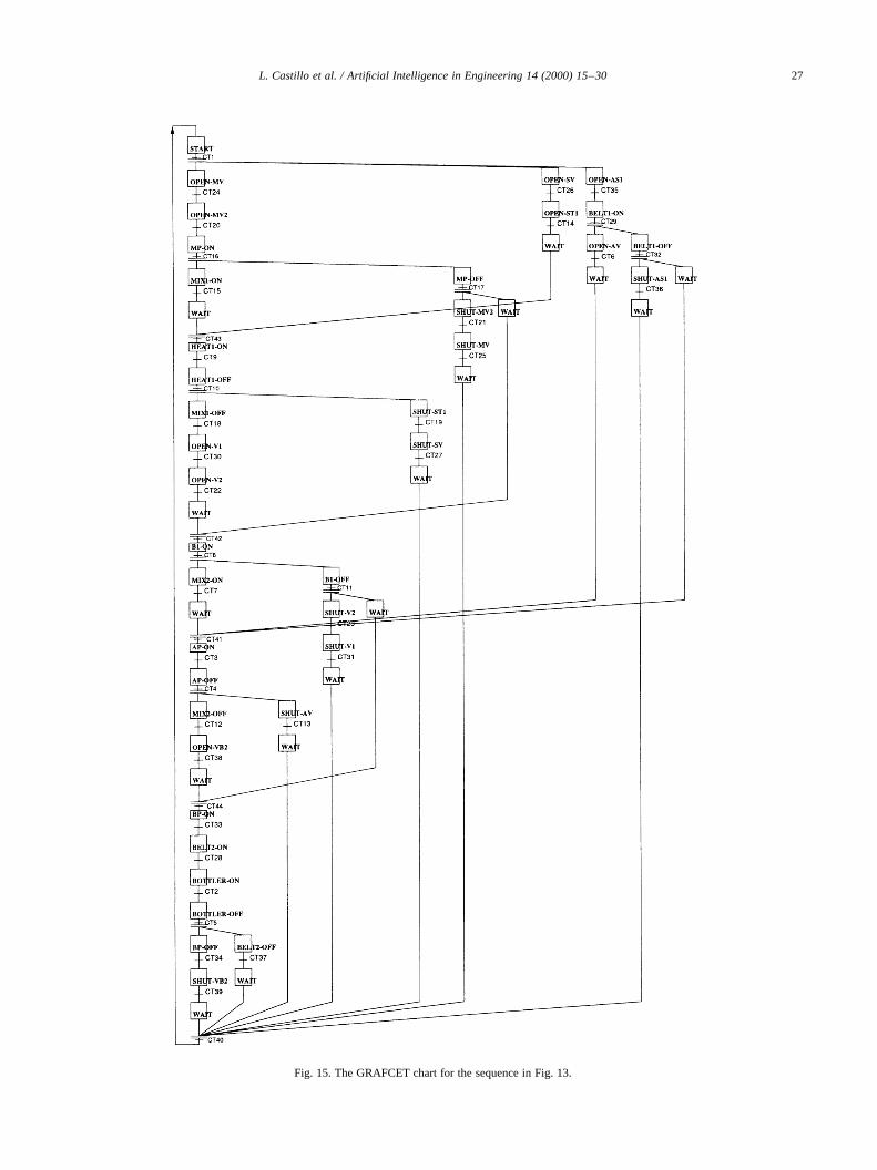
Fig. 15. The GRAFCET chart for the sequence in Fig. 13.

6. Conclusions and extensions
This work has been motivated by the need to apply arti-ficial intelligence planning techniques to the design ofcontrol programs for manufacturing systems, allowing foran error-free, fast and low cost building process for suchcontrol programs. This need has shown that the domain ofmanufacturing systems has some basic properties whichmust be taken into account in order to ensure correct reason-ing about the actions which take place in such a domain, andto ensure a sufficiently low level of detail in the final plan.Since these features do not adequately fit into known modelsof action, an effort has been made to extend both the basicmodel of action ofstrips [20] and a basic partial orderplanning scheme [21] to deal with these features. Thefinal result is the planning system presented in this paper,calledmachine, which is able to obtain control sequencesfor manufacturing systems.
Although machine has been tested successfully onseveral problems it can only be considered as a step forwardin the resolution of the problems which appear in manufac-turing systems. The reason is that this is a very rich domainwith many problems of different natures, which should betaken into account by an autonomous problem solver.However, the core of the problem solver is actually a plan-ning system and all of these problems may be built likefolders or extensions over this planning core, configuringan integrated planning system similar to OPlan-2 [31] orSIPE [28]. Some of the important problems, which wehope to deal with in the near future, are the following:
• Perhaps the most important problem is the inclusion of ametric time in order to both quantify the intervals ofactions and allow for the representation of gradualachievement of effects along this interval. In realproblems, these intervals are not perfectly quantified
L. Castillo et al. / Artificial Intelligence in Engineering 14 (2000) 15–3028
Table 4Logic formulae of triggering conditions for the GRAFCET in Fig. 15
CT1 (STATE MP OFF)∧ (STATE MV OFF)∧ (STATE MV2OFF) ∧ (STATE EP OFF) ∧ (STATE EV OFF) ∧ (STATEMIX1 OFF) ∧ (STATE HEAT1 OFF)∧ (STATE SVOFF) ∧ (STATE ST1 OFF) ∧ (STATE ST2 OFF) ∧ (STATEV1 OFF) ∧ (STATE B1 OFF) ∧ (STATE V2 OFF) ∧ (STATEHEAT2 OFF)∧ (STATE MIX2 OFF) ∧ (STATE AVOFF) ∧ (STATE AP OFF) ∧ (STATE AS1 OFF) ∧ (STATEAS2 OFF) ∧ (STATE BELT1 OFF) ∧ (STATE VB2OFF) ∧ (STATE BP OFF) ∧ (STATE BOTTLEROFF) ∧ (STATE BELT2 OFF) ∧ (CONTAINS MILK MILK-TANK) ∧ (TEMP MILK LOW)∧ (CONTAINS ENZYMEENZYME-TANK)∧ (CONTAINS FLOURADDITIVE1) ∧ (CONTAINS COCA_ADDITIVE1)
CT2 (STATE BOTTLER ON)∧ (BOTTED MILK)CT3 (STATE AP ON)∧ (ADDED MILK COCOA)∧ (FLOW
COCOA RTANK TANK2)∧ (FLOWING COCOA RTANKTANK2 AP)
CT4 (STATE AP OFF)CT5 (STATE BOTTLER OFF)CT6 (STATE AV ON)∧ (OPEN-FLOW COCOA RTANK
TANK2) ∧ (OPENING-FLOW COCOA RTANK TANK2 AV)CT7 (STATE MIX2 ON) ∧ (MIX MILK TANK2) ∧ (MIXING MILK
MIX2)CT8 (STATE B1 ON)∧ (CONTAINS MILK TANK2) ∧ (FLOW
MILK TANK1 TANK2)∧ (FLOWING MILK TANK1 TANK2B1)
CT9 (STATE HEAT1 ON)∧ (TEMP MILK HIGH)CT10 (STATE HEAT1 OFF)CT11 (STATE B1 OFF)CT12 (STATE MIX2 OFF)CT13 (STATE AV OFF)CT14 (STATE ST1 ON) ∧ (OPEN-FLOW STEAM BOILER
HEAT1) ∧ (OPENING-FLOW STEAM BOILER HEAT1 ST1)CT15 (STATE MIX1 ON) ∧ (MIX MILK TANK1) (MIXING MILK
MIX1)CT16 (STATE MP ON)∧ (CONTAINS MILK TANK1) ∧ (FLOW
MILK MILK-TANK1) ∧ (FLOWING MILK MILK-TANKTANK1 MP)
CT17 (STATE MP OFF)CT18 (STATE MIX1 OFF)CT19 (STATES ST1 OFF)CT20 (STATE MV2 ON)∧ (OPEN-FLOW MILK MILK-TANK
TANK1) ∧ (OPENING-FLOW MILK MILK-TANK TANK1MV2)
CT21 (STATE MV2 OFF)CT22 (STATE V2 ON) ∧ (OPEN-FLOW MILK TANK1
TANK2) ∧ (OPENING-FLOW MILK TANK1 TANK2 V2)CT23 (STATE V2 OFF)CT24 (STATE MV ON)∧ (OPEN-FLOW MILK-TANK
P1) ∧ (OPENING-FLOW MILK MILK-TANK P1 MV)CT25 (STATE MV OFF)CT26 (STATE SV ON)∧ (OPEN-FLOW STEAM BOILER
P2) ∧ (OPENING-FLOW STEAM BOILER P2 SV)CT27 (STATE SV OFF)CT28 (STATE BELT2 ON)∧ (CONTAINS BOTTLES
BOTTLER)∧ (FLOW BOTTLES-STORAGEBOTTLER)∧ (FLOWING BOTTLES BOTTLES-STORAGEBOTTLER BELT2)
CT29 (STATE BELT1 ON)∧ (CONTAINS COCOARTANK)∧ (FLOW COCOA ADDITIVE1RTANK)∧ (FLOWING COCOA ADDITIVE1 RTANK BELT1)
CT30 (STATE V1 ON) ∧ (OPEN-FLOW MILK TANK1B1) ∧ (OPENING-FLOW MILK TANK1 B1 V1)
CT31 (STATE V1 OFF)
Table 4 (continued)
CT32 (STATE BELT1 OFF)CT33 (STATE BP ON)∧ (CONTAINS MILK BOTTLER)∧ (FLOW
MILK TANK2 BOTTLER)∧ (FLOWING MILK TANK@BOTTLER BP)
CT34 (STATE BP OFF)CT35 (STATE AS1 ON)∧ (OPEN-FLOW COCOA ADDITIVE1
BELT1) ∧ (OPENING-FLOW COCOA ADDITIVE1 BELT1AS1)
CT36 (STATE AS1 OFF)CT37 (STATE BELT2 OFF)CT38 (STATE VB2 ON)∧ (OPEN-FLOW MILK TANK2
BOTTLER)∧ (OPENING-FLOW MILK TANK2 BOTTLERVB2)
CT39 (STATE VB2 OFF)CT40 TRUECT41 TRUECT42 TRUECT43 TRUECT44 TRUE

and they may be vague. Time map managers [22,23]seem to be very promising in this task.
• Manufactured products are really complex and aclassic conjunctive goal is not enough to deal withcomplex goals. It is necessary to define behavioralgoals as anordered set of transformations on rawproducts, this is known as arecipe. At present,machinedoes work with goals whose literals have a partial orderstructure, but this will be dealt with in a forthcomingpaper.
• In these domains, there are what could be called proce-dures: complex problems which can be decomposed intoan ordered sequence of smaller subproblems. The plan-ning system must know these procedures and it must alsoknow how to work with them. This problem pointsdirectly to HTN techniques [32].
• The control programs seen in this paper are intended towork in an open loop manner, that is, with no feedbackfrom the environment. Real control programs havefeedback from sensors in the environment and the plan-ning system must be able to include the informationsupplied by these sensors in the planning process. Thisseems to be the most challenging problem because itimplies both:
(a) The ability of the planning system to adapt itsbehavior to the different ways in which sensorsmay appear. Case-based and analogical techniquesseem very promising in this task because they alsoseem to be the techniques used by humans in thesame role.(b) The ability to include some kind of conditionalbehavior in the plan because the information givenby sensors is not always available at planning time.
• And finally, although machine has been tested suc-cessfully on the examples seen throughout this work,the search engine may be improved in order to facemore complex problems. At present we have developeda best first engine formachine, more in accordancewith the state of the art planners, but usual heuristicfunctions to guide the search [33,34] seem to givevery little information and the search process is tooslow. However, this will also be dealt in a forthcomingwork.
Acknowledgements
This work has been supported by the CICYT underproject TIC95-0453.
Appendix A. The final control programs
Control sequences obtained bymachine contain suffi-cient knowledge to be easily translated into lower levelrepresentations such as Petri nets or GRAFCET charts.This knowledge is the order relation between the actionsand the lists of requirements and effects of every action in
the sequence, which may be used as triggering conditions.2
Although the translation process and some interesting prop-erties are explained in detail in Ref. [29], Figs. 14 and 15illustrate the final translations to GRAFCET charts of thecontrol sequences in Table 2. These charts are actually avalid representation for a control program for a manufactur-ing system and they may be implemented in most knowncontrol systems. It may be seen that the main difference withrespect to the control sequences is the inclusion of synchron-ization stages in the GRAFCET (the stages named asWAIT).
References
[1] Allen JF, Hendler J, Tate A. Readings in planning. Los Altos, CA:Morgan-Kaufmann, 1990.
[2] McDermott D. Regression planning. Int J Intell Syst 1991;6:357–416.[3] McDermott D, Hendler J. Planning: what is, what it could be, an
introduction to the special issue on planning and scheduling. ArtificialIntell 1995;76:1–16.
[4] Nilsson NJ. Principles of artificial intelligence. Tioga Publishing, 1980.[5] Green C. Application of theorem proving to solving. IJCAI
1969;741–7.[6] Manna Z, Waldinger RJ. Knowledge and reasoning in program
synthesis. Artificial Intell 1975;6:175–208.[7] Waldinger RJ. Constructing programs automatically using theorem
proving. PhD thesis, Carnegie-Mellon University, 1969.[8] Aylett R, Petley G, Chung P, Soutter J, Rushton A. Planning and
chemical plan operation procedure synthesis: a case study. In: FourthEuropean Conference on Planning, 1997. p. 41–53.
[9] Klein I, Jonsson P, Backstrom C. Tractable planning for an assemblyline. In: Ghallab M, Milani A, editors. New directions in AI planning.IOS Press, 1996. p. 313–24.
[10] Gil Y. A specification of manufacturing processes for planning. Tech-nical Report CMU-CS-91-179, Carnegie Mellon University, 1991.
[11] Nau D, Gupta SK, Regli WC. AI planning versus manufacturing-operation planning: a case study. IJCAI-95 1995;1670–6.
[12] Park SC, Gervasio MT, Shaw MJ, DeJong GF. Explanation-basedlearning for intelligent process planning. IEEE Trans Systems, Man& Cybernetics 1993;23(6):1597–616.
[13] Gruver WA, Boudreaux JC. Intelligent manufacturing: programmingenvironments for CIM. London: Springer, 1993.
[14] Peterson JL. Petri nets theory and the modeling of systems. Engle-wood Cliffs, NJ: Prentice-Hall, 1981.
[15] Allen JF. Towards general theory of action and time. ArtificialIntelligence 1984;23:123–54.
[16] Pednault E. ADL: exploring the middle ground between STRIPS andthe situation calculus. Knowledge Representation, 1989.
[17] Penberthy JS, Weld DS. UCPOP: a sound, complete, partial orderplanner for ADL. In: Third International Conference on Principlesof Knowledge Representation and Reasoning, 1992. p. 103–14.
[18] Sandewall E, Ronnquist R. A representation of action structures.AAAI-86 1986;89–97.
[19] Castillo L, Gonza´lez A. MACHINE: A model of action for multi-agent domains. In: European Conference on Planning ECP-97, 1997.Electronically available at http://decsai.ugr.es/~1cv.
L. Castillo et al. / Artificial Intelligence in Engineering 14 (2000) 15–30 29
2 machine also obtains detailed descriptions of these triggering condi-tions. However, to avoid an excessive lengthening of the paper, only thedescription of the real size problem is included in Table 4. Every literal inthe table could be represented as a logical variable which can be imple-mented either as an input of the control system (when the informationprovided by the variable comes from a sensor in the manufacturing system)or as an internal or timed variable of such control system.

[20] Fikes RE, Nilsson NJ. STRIPS: A new approach to the application oftheorem proving to problem solving. Artificial Intell 1971;2:189–208.
[21] Weld D. An introduction to least commitment planning. AI Magazine1994;15(4).
[22] Dean T, McDermott D. Temporal database management. ArtificialIntelligence 1987;32:1–55.
[23] Rutten E, Hertzberz J. Temporal planner� nonlinear planner1 timemap manager. Artificial Intell Commun 1993;6:18–26.
[24] Klein I, Lindskog P, Backstrom C. Automatic creation of sequentialcontrol schemes in polynomial time. Technical Report LiTH-ISY-I-1430, Linkoping Univeristy, 1993.
[25] Soutter J. An integrated architecture for operating proceduresynthesis. PhD thesis, Loughborough University, 1996.
[26] McAllester D, Rosenblitt D. Systematic nonlinear planning. AAAI-911991;634–9.
[27] Allen JF. An interval-based representation of temporal knowledge. In1981;IJCAI-81:221–6.
[28] Wilkins DE. Practical planning: extending the classical AI planningparadigm. Los Altos, CA: Morgan Kaufmann, 1988.
[29] Castillo L, Fdez-Olivares J, Gonza´lez A. Intelligent planning ofGrafcet charts. Technical Report DECSAI-990109, University ofGranada, 1999.
[30] Castillo L, Fdez-Olivares J, Gonza´lez A. A three-level knowledgebased system for the generation of live and safe petri nets for manu-facturing systems. J Intell Manufact 1999, in press.
[31] Tate A, Drabble D, Dalton J. The use of condition types to restrictsearch in an AI planner. AAAI-94 1994;1129–34.
[32] Erol K, Hendler J, Nau D. UMCP: a sound and complete procedurefor hierarchical task-network planning. AIPS-94 1994.
[33] Gerevini A, Schubert L. Accelerating partial-order planners: sometechniques for effective search control and pruning. J Artificial IntellRes 1996;95–137.
[34] Pollack ME, Joslin D, Paolucci M. Flaw selection strategies forpartial-order planning. J Artificial Intell Res 1997;6:223–62.
L. Castillo et al. / Artificial Intelligence in Engineering 14 (2000) 15–3030