Embed Size (px)
Citation preview

© 2016, IJCSE All Rights Reserved 14
International Journal of Computer Sciences and Engineering International Journal of Computer Sciences and Engineering International Journal of Computer Sciences and Engineering International Journal of Computer Sciences and Engineering Open Access Research Paper Volume-4, Special Issue-7, Dec 2016 ISSN: 2347-2693
Automatic Feedback Control of A DC Motor Using PWM With P-
Controller
M. S. Mazinder1, S. Ahmed, S. Devya, P.K Bordoloi, T Roy
Department of Applied Electronics and Instrumentation Engineering, GIMT Guwahati, Guwahati, Assam, India
P. K. Brahma
Department of CSE and IT, GIMT Guwahati, Guwahati, Assam, India
Available online at: www.ijcseonline.org
Abstract: An automatic feedback control system has been developed to regulate the speed of a dc motor by using PWM
with P-controller. The voltage applied to the motor can be controlled by controlling the PWM duty cycle. The principle
involved is armature voltage control of speed of a dc motor at varying load conditions. Adapting close-loop control
system gives a better and more precise operating condition of a motor under varying load conditions which is often met
in practical situations. Comparison of the output voltage with the reference value is carried out with the help of a
feedback circuit which includes a P-Controller. It determines the deviation and generates a control signal to reduce the
deviation to a small value. Other types of controller, namely PI and PID, are envisaged as a part of future work.
Keywords- Automatic feedback control, Multi-vibrator, PWM technique, Duty cycle, Speed control, P-controller, Motor
Driver.
1. INTRODUCTION
The drive systems used in industrial applications require
high performance, reliability and variable speed. Electrical
drives have the advantage of ease of controllability. The
speed control of dc motor is very crucial in applications
where loading conditions are fluctuating in nature. Speed
control of dc motor could be achieved using mechanical or
electrical techniques. In the past, speed control of DC drive
was mostly mechanical requiring large-size hardware to
implement. In contrast an electrical/electronic system
results in a more compact reliable and accurate control.
Fig.1. Closed loop negative feedback system
Automatic control is the regulation of processes without
human intervention. In a feedback control loop (as shown in
figure 1), a comparator compares the measured value of a
process with a desired set value, resulting in an error signal
to change the input to the process in such a way that the loop
control provides better accuracy, as well as better transient-
and steady-state response. Some important applications of
feedback control systems are in: Rolling mills, Paper mills,
Mine windows, Hoists, Machine tools, Printing presses,
Textile mills, Excavators and Cranes. Fractional horse-
power dc drives are widely employed for positioning and
tracking.
In this work, an automatic feedback control on a dc motor
has been implemented on a Motor-generator pair employed
for electrical loading. A feedback control system for a dc
motor using the PWM technique has been built for this
purpose. . It is desired to obtain a drive that will maintain the
desired speed (at close tolerance) at varying load/torque
conditions at the driving shaft. The DC motor is an
important part of equipments in many industrial applications
requiring variable speed and load characteristics due to its
ease of controllability. Pulse Width Modulation (PWM)
technique offers many advantages in controlling the speed of
dc motors. PWM signal is a method for generating an analog
signal using digital source. PWM consists of two main
components that define its behavior: a duty cycle and a
frequency [1].
Many works on speed control of dc machine using PWM
has been done. A recent paper has been presented in the
study of D.C motor speed control through Pulse Width
International Journal of Computer Sciences and Engineering Vol.-4(7), Dec 2016, ISSN: 2347-2693
© 2016, IJCSE All Rights Reserved 15
Modulation implemented by MATLAB Simulation. In this
paper it has presented the realization of the speed control by
using Pulse Width Modulation. PWM is generated using
microcontroller 8051 and to drive the motor. H-bridge is
used which is made up of four MOSFETs. Precise control of
low torque DC motor is obtained by using simple and
inexpensive hardware. This paper shows that accurate and
precise control of small DC motors can be done effectively
and efficiently without using complicated circuitry and
costly components [2]. A PWM control based on LM324 [3]
was used to control the speed of a DC motor in both forward
and reverse directions, from fully OFF to fully ON state . As
it runs in switch mode, it is quite efficient. The proposed
system offers many advantages such as simple structure, low
cost, accurate, quite efficient, lightweight, small volume,
and bi-directional speed control. PWM-based speed control
of DC motor through RS232 interfaced with PC was used to
control the speed of a dc geared motor [4]. PWM-based
automatic closed loop speed control of DC Motor using
microcontroller [5] have been used. The implementation of
the work was done using ATmega8L microcontroller for
speed control of DC motor fed by a DC chopper. The
chopper is driven by a high-frequency PWM signal.
Controlling the PWM duty-cycle is equivalent to controlling
the motor terminal voltage, which in turn adjusts directly the
motor speed. The speed control of dc motor using
microcontroller (PIC 16F72) with PWM have been
investigated [6]. It is a closed-loop real-time control system,
where optical encoder is coupled to the motor shaft to
provide the feedback speed signal to controller. PWM
technique is used where its signal is generated in
microcontroller. The PWM signal is sent to motor driver
(using H bridge built with IGBT switches) to vary the
voltage supply to the motor to maintain constant speed.
2. SCHEMATIC BLOCK DIAGRAM
The schematic block diagram of the system is given bellow:
Fig.2. Schematic block diagram
The constituent blocks are described in the following
sections:
2.1 PWM Generator Circuit
PWM generator circuit controls the duty-cycle of the applied
voltage at the motor terminals. The main circuit components
of the PWM generator circuits are as described below-
2.1.1 Astable Pulse Generator
In an Astable multivibrator, both coupling networks provide
ac coupling through coupling capacitors. Each amplifier
stage provides phase shift of 1800 in the midband so as to
provide an overall phase shift of 3600 or 0
0 and thus a
positive feedback. The circuit therefore oscillates, provided
that the total loop gain is equal to or greater than unity. It
has no stable state. The two states of operation of astable
multivibrator are quasi-stable (temporary) states. The astable
multivibrator, therefore, makes successive transitions from
one quasi-state to the other one after a predetermined time
interval, without the aid of an external triggering signal. The
periodic time depends upon circuit time constant and
parameters.
This is a classical circuit that has been used for many years
for generating pulse waveforms.
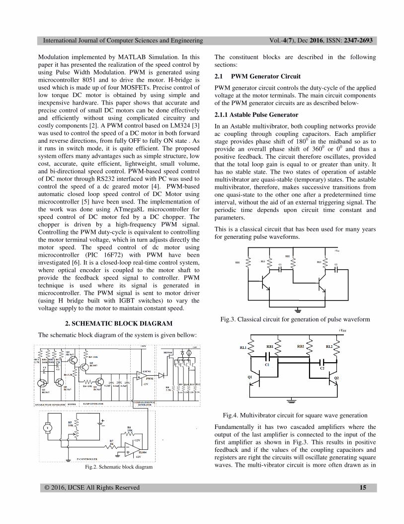
Fig.3. Classical circuit for generation of pulse waveform
Fig.4. Multivibrator circuit for square wave generation
Fundamentally it has two cascaded amplifiers where the
output of the last amplifier is connected to the input of the
first amplifier as shown in Fig.3. This results in positive
feedback and if the values of the coupling capacitors and
registers are right the circuits will oscillate generating square
waves. The multi-vibrator circuit is more often drawn as in

International Journal of Computer Sciences and Engineering Vol.-4(7), Dec 2016, ISSN: 2347-2693
© 2016, IJCSE All Rights Reserved 16
Fig.4.When oscillating one transistor turns on (saturated)
while the other turns off and after some time the situation
reverses and the on off process continues indefinitely.
Obviously this will raise a square waveform with a fixed
frequency and duty cycle. The output waveform appears at
either of the collector terminals.
2.1.2 Buffer Circuit
Fig.5: Buffer circuit
A Buffer circuit used is basically an emitter follower. It is
also a negative feedback circuit. This circuit exhibits large
input impedance, small output impedance, and a voltage
gain of approximately unity. The output voltage tends to be
in phase with the input voltage-hence the term follower.
When input signal Vs is applied to the base, the resulting
emitter current, Ie develops an output voltage Vout equal to
IeRe across the emitter resistance Re. This voltage opposes
the ac signal voltage Vs as it is in phase opposition to Vs.
Then it provides a negative current feedback. Moreover, this
voltage (Vout) feedback to the input is proportional to the
emitter current hence this circuit is called a negative current
feedback circuit. The frequency of oscillation is given
approximately by
�� � 0.65���
� � 0.65���
�� � 1�� � �
Providing Vcc>>0.7 and that RB1C2>>RL1C1 and
RB2C1>>RL2C1
2.1.3 Ramp Generator
Fig.6. Ramp Generator
This comprises of two transistors Q1 and Q2. The PNP
transistor has a capacitor as a collector load. Now when the
base of Q2 goes low, on applying a low pulse (i.e. a zero
voltage signal), the transistor turns on and the emitter
voltage becomes approximately 0.7V above ground.
Therefore the current through the resistor R (and hence the
emitter current) is equal to
���� � 0.7� ��
This is also equal (approximately) to the collector current IC
which is constant and independent of the collector voltage.
The collector circuit behaves like a constant current source.
The voltage across the capacitor C is given by
�� � 1�� ���
Here, I=Ic, which is constant
Therefore, �� � ��� � �
This equation for Vc generates a ramp waveform. The
slope depends upon Ic /C. The transistor Q1 switches off,
when the base voltage becomes low. But when the input
voltage changes to high, Q1 turns on (and Q2 turns off)
effectively shorting the capacitor C so that Vc goes to zero
(equal to VCE (Sat)).
The resultant waveform is shown in Fig.7
Fig. 7. Resultant waveform of Ramp Generator
2.1.4 Comparator Pulse Width Generator
Fig. 8. Comparator
The circuit that generates width controllable pulses is build
around a comparator. A comparator is a simple differential
amplifier with high gain (ideally infinite). It basically has

International Journal of Computer Sciences and Engineering Vol.-4(7), Dec 2016, ISSN: 2347-2693
© 2016, IJCSE All Rights Reserved 17
two inputs and one output. The output voltage is equal to the
amplification of the voltage difference between the two
inputs and because the gain of the amplifier is very high, a
small difference between (ideally zero) the inputs, the output
to swing to the positive supply voltage or the negative
supply voltage (w.r.t. ground). One of the inputs is marked
as inverting and the other as non-inverting w.r.t. the output
voltage. If the non-inverting input is more positive w.r.t. to
the inverting input the output will go positive and conversely
if the inverting input is more positive w.r.t. the non-inverting
input, the output will swing towards the negative supply.
Now if V1, the non-inverting input to the comparator is a
time-varying ramp waveform and V2 is a fixed voltage (less
the peak value of the ramp), then it is possible to generate
the waveform (at the output of the comparator) as shown in
Fig. 9.
Fig.9. Comparator output
2.1.5 Motor Driver Circuit
A Darlington pair circuit is used as a Motor Driver circuit.
The current gain provided by the Darlington pair is of the
order of few thousands. This circuit is used for driving the
motor for the following reasons:
1. Input impedance is β2Re whereas that of the emitter
follower is βRe.
2. Current gain is β2, whereas that of emitter follower is β.
3. Voltage gains of the two are identical.
3. SYSTEM LOADING AND THE FEEDBACK
CIRCUIT
3.1 Electrical Load
The controlled PWM output is fed to the motor terminals of
the motor-generator set and thus controlling the PWM duty
cycle is equivalent to controlling the motor terminal voltage.
The principle involved is armature voltage control of speed
of a dc motor. The generator which is coupled to the motor
converts the mechanical power into electrical power and that
electrical power is used for electrical loading.
3.2 PWM Generator
The operation of the PWM circuit is discussed in Section 2.1
The hardware components are briefly described in the
following sections:
3.3. Power Supplies
3.3.1 Main Circuit Supply
A step-down transformer is used in the power supply which
converts the 230V ac supply to 12V ac. The ac voltage is
converted into ±12V dc using rectifier circuit for the other
circuit applications.
3.3.2 Supply Providing Floating Ground
Five AA batteries of 1.5V each are connected in series to
build a power supply of 7.5V for tacho-generator supply
providing a floating ground.
3.3.3 Supply for M-G Set in Electrical Loading
For electrical loading, two Lead-Acid batteries of 12V dc
each are connected in series to drive the Motor-Generator
set.
3.4 Motor-Generator set
Motor
A 12V PMDC motor is used in the circuit. It is driven by a
motor driver circuit giving PWM output. It is coupled to a
dc generator and the assembly is mounted on a wooden base.
Generator
A PMDC machine of voltage rating of 12V is used as a
generator. It is coupled to the motor and is used for electrical
loading of the motor.
3.5. Feedback (Tacho) Generator
A 12V PMDC motor is used as a feedback generator. It is
also mounted on the base and is coupled to the shaft of the
M-G set through a belt-pulley arrangement. The speed ratio
NTG/NM =4.4.
3.6 Controller
Controller generates a control signal to the final control
element depending upon the deviation between the set point
and the measured value of the controlled variable. In this
work a Proportional (P) controller is used [7].
3.6.1 .Proportional Controller [P]
A Proportional control system is a type of linear feedback
control system. In Proportional controllers, the output c(t)
and the error e(t) are related by
���� � �
Taking Laplace transform of Eq.(1), we have,
��!�"�!� � �

International Journal of Computer Sciences and Engineering Vol.-4(7), Dec 2016, ISSN: 2347-2693
© 2016, IJCSE All Rights Reserved 18
The steady state error (ess) is given by
#$$ � %�&
4. EXPERIMENTAL RESULTS
Fig. 10. Speed vs. output power
The Fig.10 shows the graph between speed and output
power without feedback and, with feedback plus controller.
It is observed that when the load power varies from 0W to
1.82W, the speed of the motor varies from 1894 rpm to 657
rpm. And when the load power varies from 0W to 9.22W,
the speed of the motor will show a lesser variation from
1898 rpm to 1873 rpm i.e. feedback system gives a better
control of speed at varying loads compared to an open-loop
system and introduction of the P – type controller in the
feedback loop gives better speed regulation of the motor
Fig.11. Plot between generator output and speed at different gains of the
controller
The Fig.11 shows the graph between speed vs load current
for an automatic feedback control of a dc motor using pwm
with p-controller for gain 20, gain 10 and gain 5. It is
observed that the speed variation is under an optimal level
with gain 10. Increasing the gain of the controller upto a
certain level improves the speed regulation. Excessive gain,
on the other hand, deteriorates the speed regulations.
5. CONCLUSIONS
The work involves conceptualization, planning and
development of a PWM control of dc motor using feedback
that incorporates a controller (P-type).
All the electronic functional blocks in the system have been
organized, built and independently tested to ensure correct
and reliable performance. All the blocks are finally
integrated to build up the control system.
The system has been tested for varying load conditions. The
observations and results obtained have been analyzed to
arrive at the following conclusions.
1. PWM control of a d.c motor gives a simple and
convenient method of speed control preferably at higher
duty cycles.
2. A feedback system gives a better control of speed at
varying loads compared to an open-loop system.
3. Introduction of the P – type controller in the feedback
loop gives better speed regulation of the motor.
4. Increasing the gain of the controller up to a certain level
improves the speed regulation. Excessive gain, on the other
hand, deteriorates the speed regulation.
REFERENCES
[1]http://digital.ni.com/public.nsf/allkb/294E67623752
656686256DB800508989 [2] Mohd Samsul Islam and V.K Tripathi,”A Study of D.C
Motor Speed Control through Pulse Width Modulation
Implemented by MATLAB Simulation” International
Journal of Advanced Research in Computer and
Communication Engineering, Vol. 5, Issue 6, June 2016
[3] J. A. Mohammed, “Pulse Width Modulation for DC
Motor Control Based on LM324”, Eng. &Tech.
Journal, Vol. 31,Part (A), No.10, pp. 1882-1896, 2013
[4] J. S. Chauhan and S. Semwal, “Microcontroller Based
Speed Control of DC Geared Motor through RS-232
Interface with PC”, International Journal of
Engineering Research and Applications (IJERA), ISSN:
2248-9622, vol. 3, Issue 1, January –February 2013,
pp.778-783.
[5] A. K. Dewangan, N. Chakraborty, S. Shukla and V.
Yadu, “PWM Based Automatic Closed Loop Speed
Control of DC Motor”,International Journal of
Engineering Trends and Technology, vol. 3, Issue 2, pp.
110-112, 2012.
[6] S. Shrivastava, J. Rawat and A. Agrawal, “Controlling
DC Motor using Microcontroller (PIC16F72) with
PWM”, International Journal of Engineering Research,
vol.1, Issue 2, pp. 45-47
500
700
900
1100
1300
1500
1700
1900
0 5 10
SP
EE
D (
RP
M)
POWER (W)
Without
feedback
With
feedback
plus
controller
1350
1550
1750
0 1 2
SP
EE
D (
RP
M)
POWER (W)
Gain 20 Gain 10 Gain 5

International Journal of Computer Sciences and Engineering Vol.-4(7), Dec 2016, ISSN: 2347-2693
© 2016, IJCSE All Rights Reserved 19
[7] Surekha Bhanot, Process Control Principles and
Applications, 1st ed., vol. 1, Publisher- Oxford
University Press, 2008, pp.53
ABBREVIATION
1. M-G set: Motor-Generator Set.
2. P-Controller: Proportional Controller.
3. PI-Controller: Proportional-Integral Controller.
4. PID Controller: Proportional-Integral-Derivative
Controller.
5. PMDC: Permanent Magnet Direct Current.
6. PWM: Pulse Width Modulation.
BIOGRAPHIES
APPENDIX A
A.1. PCB FABRICATION
The fabrication of the PCB for the
controlling circuit is done at the
Network Analysis laboratory of the Department. The PCB
consists of the rectifier circuit, PWM controlling circuit and
P-Controller circuit.
The following procedure has been followed for fabrication
of the PCB:
Step 1: The layout of the PCB has been prepared by using
the EXPRESS PCB software.
Step 2: The layout is printed on a transparent sheet.
Step 3: The image is transferred from the transparent sheet
to a silk screen.
Step 4: The image is next transferred from the silk screen to
the copper clade board.
Step 5: The copper plate is next treated in a Ferric Chloride
(FeCl3) solution to obtain the final PCB.
Fig.A1: Image of the PCB on the silk screen
Fig.A2: Front view of the assembled PCB
A.2. OVERALL CIRCUITRY OF THE PROJECT
Fig.A3: Showing the overall hardware and circuitry of the
project
Mayuri Sarmah Mazinder did her B.E in
Applied Electronics and Instrumentation
Engineering in 2015 and currently pursuing
her M.Tech degree in Instrumentation and
Control Engineering from GIMT Guwahati,
Assam
Sohail Ahmed did his B.E in Applied
Electronics and Instrumentation Engineering
from GIMT Guwahati, Assam in 2015
Suditree Devya did her B.E in Applied
Electronics and Instrumentation Engineering
from GIMT Guwahati, Assam in 2015
Prof. P K Brahma was the Former Director of
GIMT Guwahati. He did his
M.S. (Electrical Engineering), University
of Califfornia, Berkeley. Currently, he is the
Guest Faculty of the Dept. of CSE at GIMT
Guwahati.
Tridib Roy is the Lab Technician in Applied
Electronics, Assam. He has worked in
different electronic companies and has
rich experience in handling various
types of electronic equipments.
Prof. P K Bordoloi is a Senior Professor in
the Dept. of AEI Engineering at GIMT
Guwahati. He did his Ph.D from Manchester
University, UK and has 40 years of teaching
experience in various institutions of Assam.


![HyperSlides: Dynamic Presentation Prototyping · content [21]; mobile “crowd” feedback during delivery 47]; and automatic feedback on speech during rehearsal [20]. works have](https://img.dokumen.tips/doc/110x75/5f0fa8ad7e708231d44540e2/hyperslides-dynamic-presentation-prototyping-content-21-mobile-aoecrowda-feedback.jpg)
![Resolver Feedback - Omega Series Digital - High …1].pdfINSTALLATION & OPERATION MANUAL Resolver Feedback - Omega Series Digital - High Bandwidth PWM Brushless Servo Amplifiers …](https://img.dokumen.tips/doc/110x75/5ade4f637f8b9ad66b8b5422/resolver-feedback-omega-series-digital-high-1pdfinstallation-operation.jpg)


![AutoFDO: Automatic Feedback-Directed Optimization for ... · Optimization; D.4 [Performance of Systems]: Design Stud-ies General Terms Performance Keywords Feedback Directed Optimization,](https://img.dokumen.tips/doc/110x75/5f16bee3b8c3fb06592f0a08/autofdo-automatic-feedback-directed-optimization-for-optimization-d4-performance.jpg)


