Embed Size (px)
Citation preview

Automatic Extraction of Three Dimensional Prismatic Machining
Features from CAD Model B.V. Sudheer Kumar*, C.S.P. Rao**
*Research Scholar, Dept. of Mechanical Engineering, NIT Warangal, A.P, India-506021
[email protected] **Professor, Dept. of Mechanical Engineering, NIT Warangal, A.P, India-506021
Abstract
Machining features recognition provides the necessary
platform for the computer aided process planning
(CAPP) and plays a key role in the integration of
computer aided design (CAD) and computer aided
manufacturing (CAM). This paper presents a new
methodology for extracting features from the
geometrical data of the CAD Model present in the form
of Virtual Reality Modeling Language (VRML) files.
First, the point cloud is separated into the available
number of horizontal cross sections. Each cross section
consists of a 2D point cloud. Then, a collection of
points represented by a set of feature points is derived
for each slice, describing the cross section accurately,
and providing the basis for a feature-extraction. These
extracted manufacturing features, gives the necessary
information regarding the manufacturing activities to
manufacture the part. Software in Microsoft Visual
C++ environment is developed to recognize the
features, where geometric information of the part is
extracted from the CAD model. By using this data, an
output file i.e., text file is generated, which gives all the
machinable features present in the part. This process
has been tested on various parts and successfully
extracted all the features.
1. Introduction
The term feature does not imply the same meaning
in different engineering disciplines. This has resulted in
several ambiguous definitions for feature. A feature, in
Computer Aided Design (CAD) software, can be called
a region of a part with some interesting geometric or
topological patterns. This meaning can refer to all sorts
of information, such as for example, shape, functional
or manufacturing information. Although many types of
features have been investigated, the most common type
of feature is the form feature, which contains both
shape information and parametric information.
Examples of form features common in many shape
models are round holes, slots, steps and pockets.
Features can also be used to represent manufacturing
information of the part. Different manufacturing
domains require different feature representations. Some
of the properties that need to be encoded by features are
assembly method, manufacturing process and
tolerances. A manufacturing feature can be defined as a
form feature, but not necessarily vice versa. Among
manufacturing features, the ones received extensive
attention is the machining features. A machining
feature can be regarded as the volume swept by a
cutting tool. In this sense, it is always a negative
(subtracted) volume, in contrast with form features that
are sometimes positive (added) volumes.
Feature data in a CAD model can be represented
either as a collection of surfaces or volumes. Surface
features are naturally used for example to describe
manufacturing tolerances or locating surfaces in fixture
design. Volumetric features on the other hand, are used
in process planning since manufacturing information
(particularly in machining) is better portrayed
volumetrically.
Most of the parts can be interpreted in terms of
machining features i.e., holes, steps, slots and pockets.
Computer Aided Process Planning (CAPP) will use
these features to generate manufacturing instructions to
produce the part. Jung Hyun Han [4] made a survey on
feature recognition and merits of several algorithms of
feature recognition i.e. graph pattern matching, cell
based decomposition, convex hull decomposition and
Hint based reasoning etc. Mike Pratt and William C.
Regli [3] gave an overview on the three major
algorithmic approaches for feature recognition and
B V Sudheer Kumar et al, International Journal of Computer Science & Communication Networks,Vol 1(3), 285-296
285
ISSN:2249-5789
mentioned several drawbacks of them. In the graph-
based algorithms, the part is represented by a graph
data structure, and is searched for particular patterns for
features. The volumetric decomposition approach
decomposes the volume of the part to be manufactured
into a set of intermediate volumes and then manipulates
the volumes to produce features. The hint-based
reasoning starts from a minimal indispensable portion
of a feature's boundary which should be present in the
part, and performs extensive geometric reasoning. Joshi
and Chang [5] developed a graph named the Attribute
Adjacency Graph (AAG) to represent features in which
each face of the part is represented as a node, and each
edge or face adjacency is represented as an arc.
Sashikumar Venkataraman [6] presented a graph based
frame work for feature recognition. The feature
recognition step involved finding similar sub graphs in
the part graph. The novelty of this framework lied in
the usage of a rich set of attributes to recognize a wide
range of features efficiently. W.F. Lu [7] gave an
approach to recognize features from a data exchanged
part model. A litany of algorithms for the identification
of design and machining features are proposed. Emad
S. Abouel Nasr [8] discussed a methodology for
extracting manufacturing features from CAD system.
The system takes a neutral file in Initial Graphics
Exchange Specification (IGES) format as input and
translates the information in the file to manufacturing
information. The boundary (B-rep) geometrical
information of the part is then analyzed by a feature
recognition program that is created specifically to
extract the features from the geometrical information
based on a geometric reasoning approach.
The basic role of the CAD is to precisely define the
geometry of the product, as it is critical to all the
subsequent activities in the product life cycle. In most
of the cases parts are designed in separate CAD
environments, which have no direct link with
manufacturing. Different CAD packages use different
types of database structures to store the information of
the part in a CAD file. In this paper CATIA V5R16 is
used for modeling the part. However other CAD soft
wares, which have an option to convert CAD data, file
into Virtual Reality Modeling Language (VRML)
format can also be used. After developing the CAD
model VRML file will be generated.
2. Virtual Reality Modeling Language
VRML, sometimes pronounced vermal, is an
acronym for the Virtual Reality Modeling Language.
Technically speaking, VRML is neither virtual reality
nor a modeling language. Virtual reality typically
implies an immersive 3D experience (such as a head-
mounted display) and 3D input devices (such as digital
gloves). VRML neither requires nor precludes
immersion. Furthermore, a true modeling language
would contain much richer geometric modeling
primitives and mechanisms. VRML provides a bare
minimum of geometric modeling features and contains
numerous features far beyond the scope of a modeling
language [17].
VRML can most easily be seen as a 3D interchange
format that supports common features such as
hierarchical transformations, light sources, geometry,
animations, visual effects, material properties and
texture mapping. VRML has been designed to be an
analog to the commonly used HTML, in that it is a
multi-platform language for publishing web content in
a relatively simple and straight-forward way.
2.1. The structure of VRML [18]
A VRML file consist of the following main sections
2.1.1. Header
The header of the file tells the VRML parser that the
file is an actual VRML file of a certain version, along
with the file´s encoding type. It has the following
format:
#VRML V2.0 utf8 [optional comment] <line
terminator>
2.1.2. Scene Graph
The scene graph contains nodes which describe
objects and their properties. It contains hierarchically
grouped geometry to provide an audio-visual
representation of objects, as well as nodes that
participate in the event generation and routing
mechanism.
2.1.3. Prototypes
A Prototype is a node type created by the user by
providing extensions to the standard set of nodes. A
prototype can be seen as the struct data type in ANSI C,
or as a macro.
2.1.4. Event Routes
Some VRML nodes generate events in response to
environmental changes or user interaction. Event routes
provide the creator of a scene means of catching these
B V Sudheer Kumar et al, International Journal of Computer Science & Communication Networks,Vol 1(3), 285-296
286
ISSN:2249-5789

events and route them into other nodes that respond to
these events.
2.1.5. Script Nodes
Script nodes are nodes used to catch and process
events from other nodes. By using Scripts, more
advanced functions can be achieved, rather than just the
sheer passing of messages that is done by the event
routing.
2.2. The VRML browser [19]
The VRML files created are interpreted and
presented by the browser. The browser can be either a
stand-alone application or a plug-in for an ordinary web
browser such as Internet Explorer. The browser
presents the geometry of the VRML scene graph along
with means of interacting, navigating and exploring the
virtual world.
The main components of the browser are the Parser,
the Scene graph and the Presentation modules. The
Parser reads the VRML file and constructs the
hierarchical structure of transformations and geometry
nodes comprising the scene graph from this
information. The presentation module renders the scene
graphically and audibly back to the user.
3. Development of Feature Recognition
Module from CAD Model
The part modeled using the CAD forms the basis for
the extraction of the features. .In this paper CATIA
V5R16 is used for modeling the component. The output
file is generated in the VRML format. Software has
been developed using the Visual C++ which can extract
the geometrical entities like surfaces, edges and
vertices.
The IndexedFaceSets of VRML file provide the
information, such as sets of coordinate points, color
values and normal vectors to identify faces, edges and
vertices. Then the automatic feature extraction
algorithm extracts all the details of the prismatic
features present. The details include type of feature,
location of the feature and necessary dimensions related
to the feature. The major features considered in this
paper are holes, steps, slots, islands and pockets. An
output file (text file) will be generated, which contains
the list of features with dimensions. The Feature
Recognition Module is clearly explained with examples
in the following section.
3.1. Feature extraction methodology
The CAD model has been developed using “CATIA
V5R16” software. From the developed CAD model
Virtual Reality Modeling Language (VRML) file is
generated. This serves as necessary input file for
feature extraction. Any CAD software, which is having
the provision of generating the VRML file can be used
for generating the model. The shape node of VRML
file contains two inner nodes, namely Appearance and
geometry IndexedFaceSet. Among those two, the
geometry IndexedFaceSets will provide the necessary
geometrical information, such as coordinate point sets
to identify faces (surfaces), edges (lines) and vertices
(points).
From the VRML file, all the points (vertices) have to
be identified.
All the lines (edges) have to be defined from the
previously identified points.
In any VRML file, the height of the object will be
measured along Y-axis, hence the y coordinate
difference of the top plane and bottom plane always
indicates the height of the part.
The point cloud is then divided into number of
horizontal planes. The number of planes will be exactly
equal to the number of different y coordinate values.
3.1.1. Hole
The hole of the CAD model in VRML file has been
represented by circular top face, circular bottom face
and two semicircular lateral surfaces. The semicircular
lateral surfaces are used to identify the diameter, x and
z coordinates of the center. The top and bottom points
of the semi circular lateral surface can be segregated
into two sets based on y coordinate value.
Procedure to find the diameter: Consider the two sets
separately, and find minimum x value and maximum x
value. The diameter can be obtained directly as the
difference of these two values.
Procedure to find the center X coordinate: the x
coordinate of the center can be obtained as the average
of minimum and maximum x values.
Procedure to find the center Z coordinate: the z
coordinate of either minimum x or maximum x can be
considered as the center Z coordinate.
B V Sudheer Kumar et al, International Journal of Computer Science & Communication Networks,Vol 1(3), 285-296
287
ISSN:2249-5789

Through Hole: if two circles with same center and
diameter, present on top and bottom planes, it indicates
presence of a through hole feature. The height of the
hole is same as the height of the part
Blind Hole: if two circles with same center and
diameter, present on top and intermediate planes, it
indicates presence of a blind hole feature. The height of
the hole is same as the difference of y coordinates of
the two planes on which the two circles are present.
Stepped Hole: if four circles are identified with same
center, and two circles with diameter D1 and the other
two with diameter D2, the height of the step1 is same
as the difference of y coordinates of the two planes on
which the two circles are present and the height of the
step2 is same as the difference of y coordinates of the
two planes on which these two circles are present.
If the sum of heights of step1 and step2 is equal to the
height of the part, the feature is stepped through hole,
else stepped blind hole
3.1.1. Blind slot The corner points on the planes F1 (top plane) and F7
(bottom plane) have to be compared considering F7 as
reference. If all the four corner points are present, and
one of the edges of top plane should have two
discontinuous lines, and the points of the top plane
except corner points should be matched with the points
of an intermediate plane, then it indicates presence of
blind slot.
Fig 1 Schematic Diagram Showing Blind Slot
The dimensions can be calculated as below.
The depth can be calculated s the distance between the
edges E9 and E7.
The length can be calculated as the distance between
the edges E11 and E8.
The width can be calculated as the distance between the
edges E10 and E13.
3.1.2. Slot
The corner points on the planes F1 (top plane) and F7
(bottom plane) have to be compared considering F7 as
reference. If all the four corner points are present, and
two opposite edges of top plane should have two
discontinuous lines, and the points of the top plane
except corner points should be matched with the points
of an intermediate plane, then it indicates presence of a
slot.
The dimensions can be calculated as below.
The depth can be calculated as the distance between the
edges E3 and E6.
The length is equal to the length of the object.
The width can be calculated as the distance between the
edges E3 and E12.
Fig 2 Schematic Diagram Showing Slot
3.1.3. Blind step
The corner points on the planes F1 (top plane) and F7
(bottom plane) have to be compared considering F7 as
reference. If any one corner is missing, and the
remaining three corner points are present, it indicates
presence of blind step at the missing corner point. In
B V Sudheer Kumar et al, International Journal of Computer Science & Communication Networks,Vol 1(3), 285-296
288
ISSN:2249-5789

the above figure the corner point exactly above V11 or
V9 is missing.
The dimensions can be calculated as below.
The depth can be calculated as the distance between the
edges (E4 and E10) or (E5 and E11)
The length can be calculated as the distance between
the edges E11 and E12.
The width can be calculated as the distance between the
edges E10 and E13.
Fig 3 Schematic Diagram Showing Blind Step
Horizontal step: Compare the edges of top plane (F1)
with the bottom reference plane (F7). If any horizontal
edge is missing, it indicates the presence of horizontal
step
The depth can be calculated as the distance between the
edges E3 and E6.
The length can be calculated as the distance between
the edges E6 and E9.
The width is equal to the width of the object.
Vertical step: Verify all the four vertical edges of the
part. If any vertical edge is missing, it indicates the
presence of vertical step.
The depth is equal to the height of the object.
The length can be calculated as the distance
The width can be calculated as the distance between the
edges E9 and E8.
Fig 4 Schematic Diagram Showing Horizontal Step
Fig 5 Schematic Diagram Showing Vertical Step
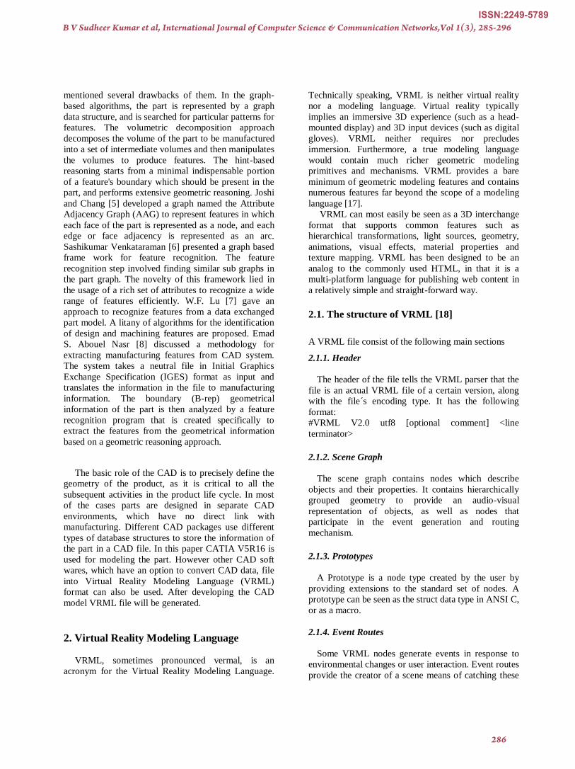
3.1.4. Pocket
Pocket: Verify all the four edges of the top plane with
respect to bottom plane edges. If all the edges are
found, and if the vertices on plane F1 except the corner
points are present on any one of the intermediate
planes, it indicates the presence of pocket.
The depth can be calculated as the distance between the
edges E6 and E11
The length can be calculated as the distance between
the edges E5 and E8.
B V Sudheer Kumar et al, International Journal of Computer Science & Communication Networks,Vol 1(3), 285-296
289
ISSN:2249-5789
The width can be calculated as the distance between the
edges E6 and E7.
Fig 6 Schematic Diagram Showing Pocket
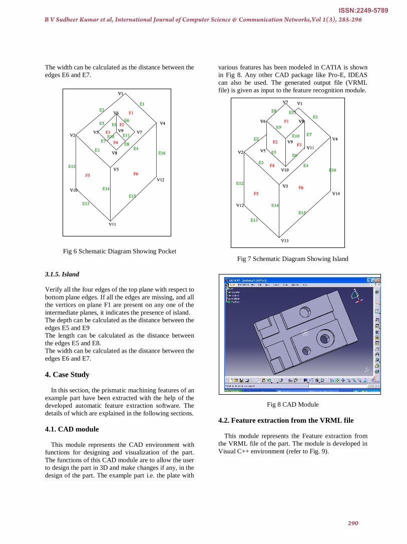
3.1.5. Island
Verify all the four edges of the top plane with respect to
bottom plane edges. If all the edges are missing, and all
the vertices on plane F1 are present on any one of the
intermediate planes, it indicates the presence of island.
The depth can be calculated as the distance between the
edges E5 and E9
The length can be calculated as the distance between
the edges E5 and E8.
The width can be calculated as the distance between the
edges E6 and E7.
4. Case Study
In this section, the prismatic machining features of an
example part have been extracted with the help of the
developed automatic feature extraction software. The
details of which are explained in the following sections.
4.1. CAD module
This module represents the CAD environment with
functions for designing and visualization of the part.
The functions of this CAD module are to allow the user
to design the part in 3D and make changes if any, in the
design of the part. The example part i.e. the plate with
various features has been modeled in CATIA is shown
in Fig 8. Any other CAD package like Pro-E, IDEAS
can also be used. The generated output file (VRML
file) is given as input to the feature recognition module.
Fig 7 Schematic Diagram Showing Island
Fig 8 CAD Module
4.2. Feature extraction from the VRML file
This module represents the Feature extraction from
the VRML file of the part. The module is developed in
Visual C++ environment (refer to Fig. 9).
B V Sudheer Kumar et al, International Journal of Computer Science & Communication Networks,Vol 1(3), 285-296
290
ISSN:2249-5789

Fig 9 The Feature Recognition Module in the Visual
C++ environment.
The coordinates are grouped so that they represent the
features altogether. The function of the feature
extraction module is to extract the coordinates which
represent the features present in the part from the
VRML file generated form the CAD module. The
VRML file is converted into text file which has the list
of features.
This output is given as input for the next module.
The following file shows the output file for the given
problem.
OUTPUT
Below are the circles identified
Center (x:y:z): (30.000000 : 0.000000 : -30.000000) ,
Diameter : 20.000000
Center (x:y:z): (-20.000000 : 0.000000 : -40.000000) ,
Diameter : 18.000000
Center (x:y:z): (10.000000 : 10.000000 : 40.000000) ,
Diameter : 24.000000
Center (x:y:z): (30.000000 : 30.000000 : -30.000000) ,
Diameter : 20.000000
Center (x:y:z): (30.000000 : 30.000000 : -30.000000) ,
Diameter : 40.000000
Center (x:y:z): (10.000000 : 40.000000 : 40.000000) ,
Diameter : 24.000000
Center (x:y:z): (-20.000000 : 40.000000 : -40.000000) ,
Diameter : 18.000000
Center (x:y:z): (30.000000 : 40.000000 : -30.000000) ,
Diameter : 40.000000
Blind Hole
Center of the hole is 10.000000 : 40.000000
Height of the hole is 30.000000
Diameter of the hole is 24.000000
Center (x,y,z) - Diameter
(10.000000:10.000000:40.000000) - 24.000000
Center (x,y,z) - Diameter
(10.000000:40.000000:40.000000) - 24.000000
Through Hole
Center of the hole is -20.000000 : -40.000000
Height of the hole is 40.000000
Diameter of the hole is 18.000000
Center (x,y,z) - Diameter
(-20.000000:0.000000:-40.000000) - 18.000000
Center (x,y,z) - Diameter
(-20.000000:40.000000:-40.000000) - 18.000000
Stepped Hole
Center of the hole is 30.000000 : -30.000000
Height of the hole is 30.000000
Diameter of the hole is 20.000000
Center (x,y,z) - Diameter
(30.000000:0.000000:-30.000000) - 20.000000
Center (x,y,z) - Diameter
(30.000000:30.000000:-30.000000) - 20.000000
Center (x,y,z) - Diameter
(30.000000:30.000000:-30.000000) - 40.000000
Center (x,y,z) - Diameter
(30.000000:40.000000:-30.000000) - 40.000000
Before processing for steps below are the planes
identified.
Vertices of Plane 40.000000
Boundaries (x,z) (Min, Max) -- (70.000000:-
100.000000), (-60.000000:60.000000)
Non vertex Points are 20
vertex (x:z): 70.000000 : 60.000000
vertex (x:z): 70.000000 : 20.000000
vertex (x:z): 70.000000 : -60.000000
vertex (x:z): 70.000000 : 0.000000
vertex (x:z): -40.000000 : -60.000000
vertex (x:z): -40.000000 : 0.000000
vertex (x:z): -40.000000 : 20.000000
vertex (x:z): -40.000000 : 60.000000
vertex (x:z): -60.000000 : 60.000000
vertex (x:z): -60.000000 : -60.000000
vertex (x:z): -60.000000 : 0.000000
vertex (x:z): -60.000000 : 20.000000
vertex (x:z): -70.000000 : 60.000000
vertex (x:z): -70.000000 : 40.000000
vertex (x:z): -80.000000 : -30.000000
B V Sudheer Kumar et al, International Journal of Computer Science & Communication Networks,Vol 1(3), 285-296
291
ISSN:2249-5789

vertex (x:z): -80.000000 : -60.000000
vertex (x:z): -100.000000 : 40.000000
vertex (x:z): -100.000000 : -30.000000
vertex (x:z): -100.000000 : 0.000000
vertex (x:z): -100.000000 : 20.000000
Vertex Points are 0
Vertices of Plane 25.000000
Boundaries (x,z) (Min, Max) -- (-70.000000:-
100.000000), (40.000000:60.000000)
Non vertex Points are 4
vertex (x:z): -70.000000 : 40.000000
vertex (x:z): -70.000000 : 60.000000
vertex (x:z): -100.000000 : 40.000000
vertex (x:z): -100.000000 : 60.000000 -- BOUNDARY
Vertex Points are 1
Vertices of Plane 22.000000
Boundaries (x,z) (Min, Max) -- (70.000000:-
100.000000), (-60.000000:60.000000)
Non vertex Points are 12
vertex (x:z): 70.000000 : 20.000000
vertex (x:z): 70.000000 : 0.000000
vertex (x:z): -40.000000 : -60.000000
vertex (x:z): -40.000000 : 0.000000
vertex (x:z): -40.000000 : 20.000000
vertex (x:z): -40.000000 : 60.000000
vertex (x:z): -60.000000 : -60.000000
vertex (x:z): -60.000000 : 60.000000
vertex (x:z): -60.000000 : 0.000000
vertex (x:z): -60.000000 : 20.000000
vertex (x:z): -100.000000 : 0.000000
vertex (x:z): -100.000000 : 20.000000
Vertex Points are 0
Vertices of Plane 20.000000
Boundaries (x,z) (Min, Max) -- (-80.000000:-
100.000000), (-60.000000:-30.000000)
Non vertex Points are 4
vertex (x:z): -80.000000 : -60.000000
vertex (x:z): -80.000000 : -30.000000
vertex (x:z): -100.000000 : -60.000000 --
BOUNDARY
vertex (x:z): -100.000000 : -30.000000
Vertex Points are 1
Vertices of Plane 18.000000
Boundaries (x,z) (Min, Max) --
(100.000000:70.000000), (-60.000000:60.000000)
Non vertex Points are 4
vertex (x:z): 100.000000 : -60.000000 -- BOUNDARY
vertex (x:z): 100.000000 : 60.000000 -- BOUNDARY
vertex (x:z): 70.000000 : 60.000000
vertex (x:z): 70.000000 : -60.000000
Vertex Points are 2
Vertices of Plane 0.000000
Boundaries (x,z) (Min, Max) --
(100.000000:100.000000), (-60.000000:60.000000)
Non vertex Points are 2
vertex (x:z): 100.000000 : -60.000000 -- BOUNDARY
vertex (x:z): 100.000000 : 60.000000 -- BOUNDARY
Vertex Points are 2
No Step on the right side
No Step on the bottom side
No Step on the top side
After processing for Max Z steps
Below are the Planes identified
Vertices of Plane 40.000000
Boundaries (x,z) (Min, Max) -- (70.000000:-
100.000000), (-60.000000:60.000000)
Non vertex Points are 20
vertex (x:z): 70.000000 : 60.000000
vertex (x:z): 70.000000 : 20.000000
vertex (x:z): 70.000000 : -60.000000
vertex (x:z): 70.000000 : 0.000000
vertex (x:z): -40.000000 : -60.000000
vertex (x:z): -40.000000 : 0.000000
vertex (x:z): -40.000000 : 20.000000
vertex (x:z): -40.000000 : 60.000000
vertex (x:z): -60.000000 : 60.000000
vertex (x:z): -60.000000 : -60.000000
vertex (x:z): -60.000000 : 0.000000
vertex (x:z): -60.000000 : 20.000000
vertex (x:z): -70.000000 : 60.000000
vertex (x:z): -70.000000 : 40.000000
vertex (x:z): -80.000000 : -30.000000
vertex (x:z): -80.000000 : -60.000000
vertex (x:z): -100.000000 : 40.000000
vertex (x:z): -100.000000 : -30.000000
vertex (x:z): -100.000000 : 0.000000
vertex (x:z): -100.000000 : 20.000000
Vertex Points are 0
Vertices of Plane 25.000000
Boundaries (x,z) (Min, Max) -- (-70.000000:-
100.000000), (40.000000:60.000000)
Non vertex Points are 4
vertex (x:z): -70.000000 : 40.000000
vertex (x:z): -70.000000 : 60.000000
vertex (x:z): -100.000000 : 40.000000
vertex (x:z): -100.000000 : 60.000000 -- BOUNDARY
Vertex Points are 1
Vertices of Plane 22.000000
Boundaries (x,z) (Min, Max) -- (70.000000:-
100.000000), (-60.000000:60.000000)
Non vertex Points are 12
vertex (x:z): 70.000000 : 20.000000
vertex (x:z): 70.000000 : 0.000000
vertex (x:z): -40.000000 : -60.000000
vertex (x:z): -40.000000 : 0.000000
vertex (x:z): -40.000000 : 20.000000
vertex (x:z): -40.000000 : 60.000000
B V Sudheer Kumar et al, International Journal of Computer Science & Communication Networks,Vol 1(3), 285-296
292
ISSN:2249-5789

vertex (x:z): -60.000000 : -60.000000
vertex (x:z): -60.000000 : 60.000000
vertex (x:z): -60.000000 : 0.000000
vertex (x:z): -60.000000 : 20.000000
vertex (x:z): -100.000000 : 0.000000
vertex (x:z): -100.000000 : 20.000000
Vertex Points are 0
Vertices of Plane 20.000000
Boundaries (x,z) (Min, Max) -- (-80.000000:-
100.000000), (-60.000000:-30.000000)
Non vertex Points are 4
vertex (x:z): -80.000000 : -60.000000
vertex (x:z): -80.000000 : -30.000000
vertex (x:z): -100.000000 : -60.000000 --
BOUNDARY
vertex (x:z): -100.000000 : -30.000000
Vertex Points are 1
Vertices of Plane 18.000000
Boundaries (x,z) (Min, Max) --
(70.000000:70.000000), (-60.000000:60.000000)
Non vertex Points are 2
vertex (x:z): 70.000000 : -60.000000 -- BOUNDARY
vertex (x:z): 70.000000 : 60.000000 -- BOUNDARY
Vertex Points are 2
Vertices of Plane 0.000000
Boundaries (x,z) (Min, Max) --
(70.000000:100.000000), (-60.000000:60.000000)
Non vertex Points are 2
vertex (x:z): 100.000000 : -60.000000 -- BOUNDARY
vertex (x:z): 100.000000 : 60.000000 -- BOUNDARY
Vertex Points are 2
No steps in the plane 40.000000
Before processing for Blind Steps
No Blind Step on the Bottom Left Corner
No Blind Step on the Bottom Left Corner
No steps in the plane 40.000000
Before processing for Slots
START OF THROUGH SLOT
X, Y, Z co ordinates in terms of Range (MIN , MAX)
X co ordinate is -40.000000 60.000000
Y co ordinate is 22.000000 40.000000
Z co ordinate is -60.000000 60.000000
X, Y, Z co ordinates in terms of vertices
-40.000000 40.000000 -60.000000
-60.000000 40.000000 -60.000000
-60.000000 40.000000 -60.000000
-40.000000 40.000000 -60.000000
-40.000000 22.000000 -60.000000
-60.000000 22.000000 -60.000000
-60.000000 22.000000 60.000000
-40.000000 22.000000 60.000000
<------------------END--------------->
START OF BLIND SLOT
X, Y, Z co ordinates in terms of Range (MIN , MAX)
X co ordinate is -60.000000 -100.000000
Y co ordinate is 22.000000 40.000000
Z co ordinate is 0.000000 20.000000
X, Y, Z co ordinates in terms of vertices
-60.000000 40.000000 0.000000
-100.000000 40.000000 0.000000
-100.000000 40.000000 20.000000
-60.000000 40.000000 20.000000
-60.000000 22.000000 0.000000
-100.000000 22.000000 0.000000
-100.000000 22.000000 20.000000
-60.000000 22.000000 20.000000
<------------------END--------------->
START OF BLIND SLOT
X, Y, Z co ordinates in terms of Range (MIN , MAX)
X co ordinate is 70.000000 -40.000000
Y co ordinate is 22.000000 40.000000
Z co ordinate is 0.000000 20.000000
X, Y, Z co ordinates in terms of vertices
70.000000 40.000000 0.000000
-40.000000 40.000000 0.000000
-40.000000 40.000000 20.000000
70.000000 40.000000 20.000000
70.000000 22.000000 0.000000
-40.000000 22.000000 0.000000
-40.000000 22.000000 20.000000
70.000000 22.000000 20.000000
<------------------END--------------->
START OF BLIND STEP
X, Y, Z co ordinates in terms of Range (MIN , MAX)
X co ordinate is -70.000000 -100.000000
Y co ordinate is 25.000000 40.000000
Z co ordinate is 40.000000 60.000000
X, Y, Z co ordinates in terms of vertices
-70.000000 40.000000 40.000000
-100.000000 40.000000 40.000000
-100.000000 40.000000 60.000000
-70.000000 40.000000 60.000000
-70.000000 25.000000 40.000000
-100.000000 25.000000 40.000000
-100.000000 25.000000 60.000000
-70.000000 25.000000 60.000000
<------------------END--------------->
START OF BLIND STEP
X, Y, Z co ordinates in terms of Range (MIN , MAX)
B V Sudheer Kumar et al, International Journal of Computer Science & Communication Networks,Vol 1(3), 285-296
293
ISSN:2249-5789

X co ordinate is -80.000000 -100.000000
Y co ordinate is 20.000000 40.000000
Z co ordinate is -60.000000 -30.000000
X, Y, Z co ordinates in terms of vertices
-80.000000 40.000000 -60.000000
-100.000000 40.000000 -60.000000
-100.000000 40.000000 -30.000000
-80.000000 40.000000 -30.000000
-80.000000 20.000000 -60.000000
-100.000000 20.000000 -60.000000
-100.000000 20.000000 -30.000000
-80.000000 20.000000 -30.000000
<------------------END--------------->
START OF THROUGH STEP
X, Y, Z co ordinates in terms of Range (MIN , MAX)
X co ordinate is 100.000000 70.000000
Y co ordinate is 18.000000 40.000000
Z co ordinate is -60.000000 60.000000
X, Y, Z co ordinates in terms of vertices
100.000000 40.000000 -60.000000
70.000000 40.000000 -60.000000
70.000000 40.000000 60.000000
100.000000 40.000000 60.000000
100.000000 18.000000 -60.000000
70.000000 18.000000 -60.000000
70.000000 18.000000 60.000000
100.000000 18.000000 60.000000
<------------------END--------------->
After processing for Slots
Below are the Planes identified
Vertices of Plane 40.000000
Boundaries (x,z) (Min, Max) –
(70.000000:-100.000000), (-60.000000:60.000000)
Non vertex Points are 4
vertex (x:z): -100.000000 : -60.000000
vertex (x:z): -100.000000 : 60.000000
vertex (x:z): 70.000000 : -60.000000
vertex (x:z): 70.000000 : 60.000000
Vertex Points are 2
Vertices of Plane 25.000000
Boundaries (x,z) (Min, Max) –
(-70.000000:-100.000000), (40.000000:60.000000)
Non vertex Points are 1
vertex (x:z): -100.000000 : 60.000000 -- BOUNDARY
Vertex Points are 1
Vertices of Plane 22.000000
Boundaries (x,z) (Min, Max) –
(70.000000:-100.000000), (-60.000000:60.000000)
Non vertex Points are 0
Vertex Points are 0
Vertices of Plane 20.000000
Boundaries (x,z) (Min, Max) –
(-80.000000:-100.000000), (-60.000000:-30.000000)
Non vertex Points are 1
vertex (x:z): -100.000000 : -60.000000
Vertex Points are 1
Vertices of Plane 18.000000
Boundaries (x,z) (Min, Max) --
(70.000000:70.000000), (-60.000000:60.000000)
Non vertex Points are 2
vertex (x:z): 70.000000 : -60.000000 -- BOUNDARY
vertex (x:z): 70.000000 : 60.000000 -- BOUNDARY
Vertex Points are 2
Vertices of Plane 0.000000
Boundaries (x,z) (Min, Max) --
(70.000000:100.000000), (-60.000000:60.000000)
Non vertex Points are 2
vertex (x:z): 100.000000 : -60.000000 -- BOUNDARY
vertex (x:z): 100.000000 : 60.000000 -- BOUNDARY
Vertex Points are 2
5. Conclusions
This paper proposes a novel approach towards the
integration of CAD and CAPP. The geometrical data
obtained from a CAD model is utilized to extract the
three dimensional features. A program in Visual C++
environment is being used to extract the features from
VRML file. The list of features can be obtained in an
output text file By using this approach manufacturing
feature recognition of components can be done using
VRML file format.
References
[1] Nafis Ahmad, and A.F.M. Anwarul Haque.,
“Manufacturing feature recognition of parts Using
DXF file”, 4th International Conference on
Mechanical Engineering, December 2001, Dhaka,
Bangladesh. pp. 111-115.
[2] T. Dereli, and H. I. Filiz, “Optimization of Process
Planning functions by Genetic algorithm”,
Computers and Industrial Engineering, 1999, Vol.
36, pp. 281-308.
[3] Mike Pratt and William C. Regli, “Manufacturing
Feature Recognition from Solid Models: A Status
Report”, IEEE transactions on robotics and
automation, 2000, vol. 16, no. 6, pp. 782-796.
[4] Jung Hyun Han, “Survey on Feature Research,
Institute for Robotics and Intelligent systems”,
USC, USA, 1996. (Technical report IRIS-96-346)
[5] S. Joshi, and T. C. Chang, “Graph Based
Heuristics for Recognition of Machined Features
B V Sudheer Kumar et al, International Journal of Computer Science & Communication Networks,Vol 1(3), 285-296
294
ISSN:2249-5789

from 3D Solid Model”, Computer Aided Design,
1988, Vol. 20, pp. 58-66.
[6] Sashikumar Venkataraman, “A Graph based Frame
work for Feature recognition”, ACM 2001 1-
58113-366-9/01/06, 2001.
[7] W.F. Lu, “An approach to identify design and
manufacturing features from data exchanged part
model”, Computer-Aided Design, 2003, Vol. 35,
pp. 979–993.
[8] Emad S. Abouel Nasr, “A new methodology for
extracting manufacturing features from CAD
system”, Computers & Industrial Engineering,
2006, Vol. 51, pp. 389–415.
[9] Murata Tadao, “Petri Nets: Properties, Analysis
and applications”. IEEE Transactions on Electrical
Engineering and Computer Science, 1989.
[10] K. Srihari, and C. R. Emerson, “Petri nets in
dynamic process planning”, Computers &
Industrial Engineering, 1990, Vol. 19, pp. 447–
451.
[11] J. A. Cecil, C. R. Emerson, K. Srihari, “A review
of Petri net applications in process planning”,
International Journal of Advanced Manufacturing
Technology, 1992 , Vol. 7, pp. 168–177.
[12] P. Xirouchakis and D. Kiritsis, “A generic Petri net
model for disassembly planning processes”,
presented at TMCE’96, Budapest, 1996
[13] D. Kiritsis and M. Porchet, “A generic Petri net
model for dynamic process planning and sequence
optimization”. Adv. Engineering Software, 1996,
Vol. 25, No. 1, pp. 61–71.
[14] D. Kiritsis, K. P. Neuendorf, and P. Xirouchakis,
“Petri net techniques for process planning cost
estimation”, Advances in Engineering Software,
1999, Vol. 30, pp, 375–387.
[15] J. M. Usher, and R. O. Bowden, “The application
of genetic algorithms to operation sequencing for
use in computer-aided process planning”,
Computers & Industrial Engineering, 1996, Vol.
30, No.4, pp. 999-1013.
[16] H.B.Marri, A. Gunasekaran, and R. J. Grieve,
“Computer aided process planning: A state of art
survey”, International journal of Manufacturing
Technology, 1998, Vol. 14, pp. 261-268.
[17] Ramesh Naidu Ande, “Integrated VRML, JAVA,
XML and HTML in a web based tool”, SCSC,
2004.
[18] Don Brutzman, “The Virtual Reality Modeling
Language and Java, Communications of the
ACM”, 1998, vol. 41 no. 6, pp. 57-64.
[19] Kian-Huat Tan, Tze Leong Yew, and Kurt
Gramoll, “Understanding Machine Operations and
Manufacturing using VRML”, Am. Soc. of
Engineering Educ, (ASEE) 1999 Conf., June 20 -
23, Charlotte, NC, 1999.
[20] Anil Sawhney, Andre Mund, and Jennifer Marble,
“Simulation of the Structural Steel Erection
Process”, Proceedings of the 31st Winter
Simulation Conference, 1999.
[21] WD Version 0.9.0, “Software and Systems
Engineering – High-level Petri Nets Part 2:
Transfer Format”, International Standard ISO/IEC
15909-2 June 23, 2005.
B V Sudheer Kumar et al, International Journal of Computer Science & Communication Networks,Vol 1(3), 285-296
295
ISSN:2249-5789

APPENDIX-A: Solid Model of the Part Used to Extract the Features
B V Sudheer Kumar et al, International Journal of Computer Science & Communication Networks,Vol 1(3), 285-296
296
ISSN:2249-5789


