Embed Size (px)
Citation preview

Automatic Blood Pressure Monitor
1WMPD4000206J 1303

© 2013 A&D Company, Limited All rights reserved. No part of this publication may be reproduced, transmitted, transcribed, or translated into any language in any form by any means without the written permission of A&D Company, Limited. The contents of this manual and the specifications of the instrument covered by this manual are subject to change for improvement without notice.
i
WARNING DEFINITIONS The warnings described in this manual have the following meanings:
WARNING Important information to alert you to a situation that might cause injury and/or damage to your property if instructions are not followed.
CAUTION Important information to alert you to a situation that might cause minor injury and/or damage to your property if instructions are not followed.
Note Important information that helps users operate the device.

ii
COMPLIANCE Compliance with the European Directive 93/42/EEC for Medical Products This device conforms to the following requirements: European Directive 93/42/EEC for Medical Products
act; Medical Products Act; European Standards for Electrical Equipment EN 60601-1 (General Safety
Provisions), EN 60601-1-2 and EN 55011 (Electromagnetic Compatibility); European Standards
pertaining to Non Invasive Blood Pressure Instruments EN 1060-1(General Requirements), EN 1060-3
(Supplementary Requirements for Electromechanical Blood Pressure Measuring Systems).
This is evidenced by the mark of conformity accompanied by the reference number of a designated authority.
This device was designed for use by adults only.
Compliance with the Australian EMC Frame Work This device conforms to the following requirements: EMC Emission Standard for Industrial, Scientific and
Medical Equipment AS/NZS 2064-1997, EMC Generic Immunity standard AS/NZS 4252.1-1994. This is
evidenced by the C-Tick label.
Environment for use The device is for use in offices, sports facilities, and hospitals (waiting rooms), etc.
NOTE This device does not have the function of automatic cycling measurement. Therefore, a part of this device does not conform to IEC60601-2-30.

iii
SAFETY PRECAUTIONS WARNING
Grounding To avoid electrical shock, connect the power cable to an electrical outlet having a ground terminal for grounding the device.
Fuse To avoid a fire hazard, use only a fuse of the proper type, voltage and current rating as specified on the rear panel. Never bypass a fuse by shorting across the fuse holder and connectors.
Service Internal service or adjustment to this device should be performed by a qualified person only. Do not disassemble or modify the device
Device failure If a device failure occurs, promptly stop using it. Have the patient remove their arm from the device and secure the patient’s safety. Turn the power off and disconnect the power cable from the electrical outlet. Affix a notice such as “Out of Order” and “Do Not Use” on the device. Ask the nearest dealer for services
To interpret blood pressure measurements Only a trained medical professional is qualified to interpret the blood pressure measurements. No device can replace regular medical checkups by a doctor. A doctor should verify the blood pressure measurements before making adjustments to medication.
If the device gets wet because of a liquid spill If the device gets wet, promptly stop using it. Have the patient remove their arm from the device and secure the patient’s safety. Turn the power off and disconnect the power cable from the electrical outlet. Affix a notice such as “Out of Order” and “Do Not Use” on the device. Ask the nearest dealer for service.
CAUTION
In case of emergency Press the EMERGENCY STOP switch located on the front of the device. This will release the air in the arm cuff so that the arm can be removed easily. It also operates if there is a power failure.
To stop the operation at any time Press the START/STOP switch located on the display panel. The quick exhaust will release the air in the arm cuff and the arm cuff will become loose.
Maintenance/Inspection Check all functions periodically. Ask the nearest dealer for this inspection. Do not disassemble or modify the device. If using the device for the first time after an extended period of storage, check the device for proper operation.

iv
GENERAL PRECAUTIONS Obey the following precautions for safe and correct usage. Precautions unique to the TM-2655/TM-2655P appear on the relevant pages in this manual. Read the manual thoroughly before use. When installing and storing the device
Install or store the device away from moisture. Do not install or store the device where the device may be badly affected by extreme temperature,
humidity, direct sunlight, draft, dust, salinity or sulfur content in the air. Do not install or store the device where chemicals, and corrosive or explosive gases are stored or
present. Install or store the device in a secure, level and stable location. Install or store the device where adequate power is provided. (Where a medical 3P electrical outlet
is provided.) Before use
Check to make sure the device operates safely and accurately. Check all cables for proper connection. When other electrical equipment is used nearby, at the same time, a diagnostic error or dangerous
situation may occur. Check all connections to make sure they do not interfere with each other. When telemeters are used, check that mutual interference will not cause a problem.
During use Check the patient and the device during use. If medical or operational problems are found in the device or the patient, stop using the device
immediately, check the status of the patient and take proper action. Do not use the device during MRI scanning. Do not use the device on a patient using a heart-lung machine. High frequency interference by electrosurgery or energy discharged by a defibrillator may damage
the device. Follow the precautions described in the manual for each device. Do not use a cellular telephone near the device. It could affect the device’s operation. The personal computer and medical equipment connected to the device are not allowed to be in the
patient area. The personal computer used must conform to IEC60950
After use
Follow the predetermined procedure to return the operation switches to their original positions, and then turn off the power.
Do not forcibly pull out the cables. Hold the connector with your hand when disconnecting the cable.
Keep the device clean and in proper operating condition so that it can be used without problem during the next operation.
Clean the accessories and arrange them before storage.
Environmental protection Remove the built-in lithium battery from the device when the device is to be disposed of. This device, any part of, and the built-in lithium battery are not treated as ordinary household waste,
and must be disposed of according to the applicable regulations.

1
CONTENTS
WARNING DEFINITIONS....................................................................................................... I
COMPLIANCE....................................................................................................................... II
SAFETY PRECAUTIONS..................................................................................................... III
GENERAL PRECAUTIONS ................................................................................................. IV
CONTENTS........................................................................................................................... 1
1. INTRODUCTION ............................................................................................................... 3
1-1 Features.......................................................................................................................................................3 1-2 Unpacking and Inspection ...........................................................................................................................4 1-3 Specifications...............................................................................................................................................5
2. PART NAMES ................................................................................................................... 6
2-1 Main Unit......................................................................................................................................................6 2-2 Rear Panel ................................................................................................................................................7 2-3 Symbols .......................................................................................................................................................7
3. INSTALLATION................................................................................................................. 9
4. OPERATION.................................................................................................................... 10
5. SETTING THE CLOCK ................................................................................................... 12
5-1 Clock Adjustment Mode.............................................................................................................................12 5-2 A Setting Example......................................................................................................................................12
6. INSTALLING THE PRINTER PAPER.............................................................................. 14
7. SETTING THE FUNCTIONS ........................................................................................... 16
7-1 Function Setting Mode...............................................................................................................................16 7-2 Description of the Functions ......................................................................................................................17 7-3 Printing Samples........................................................................................................................................18
8. COMMUNICATION SPECIFICATIONS ........................................................................... 19
8-1 Channel 1 : Miniature 8-pin DIN ................................................................................................................19 8-2 Channel 2: D-sub 9-pin..............................................................................................................................20

2
9. MAINTENANCE
9-1 Replacing the Arm Cuff Cover .................................................................................................................. 21 9-2 Replacing the Fuses ................................................................................................................................. 22 9-3 Checking the Counter ............................................................................................................................... 22
Displaying the counter................................................................................................................................. 22 Resetting the counter .................................................................................................................................. 23 Printing the counter graph........................................................................................................................... 23
9-4 Error Codes .............................................................................................................................................. 23 9-5 Maintenance ............................................................................................................................................. 23 9-6 Cleaning.................................................................................................................................................... 23 9-7 Options and Consumables ....................................................................................................................... 24
10. TROUBLESHOOTING...................................................................................................25
11. EXTERNAL DIMENSIONS.............................................................................................26
APPENDIX: EMC INFORMATION.......................................................................................27
3
1.INTRODUCTION
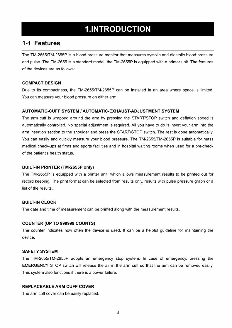
1-1 Features
The TM-2655/TM-2655P is a blood pressure monitor that measures systolic and diastolic blood pressure
and pulse. The TM-2655 is a standard model; the TM-2655P is equipped with a printer unit. The features
of the devices are as follows:
COMPACT DESIGN Due to its compactness, the TM-2655/TM-2655P can be installed in an area where space is limited.
You can measure your blood pressure on either arm.
AUTOMATIC-CUFF SYSTEM / AUTOMATIC-EXHAUST-ADJUSTMENT SYSTEM The arm cuff is wrapped around the arm by pressing the START/STOP switch and deflation speed is
automatically controlled. No special adjustment is required. All you have to do is insert your arm into the
arm insertion section to the shoulder and press the START/STOP switch. The rest is done automatically.
You can easily and quickly measure your blood pressure. The TM-2655/TM-2655P is suitable for mass
medical check-ups at firms and sports facilities and in hospital waiting rooms when used for a pre-check
of the patient’s health status.
BUILT-IN PRINTER (TM-2655P only) The TM-2655P is equipped with a printer unit, which allows measurement results to be printed out for
record keeping. The print format can be selected from results only, results with pulse pressure graph or a
list of the results.
BUILT-IN CLOCK The date and time of measurement can be printed along with the measurement results.
COUNTER (UP TO 999999 COUNTS) The counter indicates how often the device is used. It can be a helpful guideline for maintaining the
device.
SAFETY SYSTEM The TM-2655/TM-2655P adopts an emergency stop system. In case of emergency, pressing the
EMERGENCY STOP switch will release the air in the arm cuff so that the arm can be removed easily.
This system also functions if there is a power failure.
REPLACEABLE ARM CUFF COVER The arm cuff cover can be easily replaced.
4
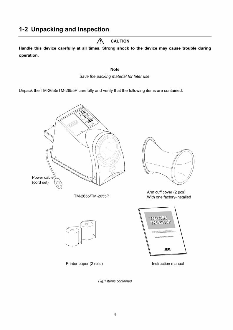
1-2 Unpacking and Inspection
CAUTION Handle this device carefully at all times. Strong shock to the device may cause trouble during operation.
Note Save the packing material for later use.
Unpack the TM-2655/TM-2655P carefully and verify that the following items are contained.
Fig.1 Items contained

5
1-3 Specifications Table 1 Specifications
Performance specifications
General
Power supply 120VAC 60 Hz (For USA area) 230VAC 50 Hz (For Europe area) (factory-preset)
Power consumption Approx. 40VA
Protection against electrical shock Class I , Type B
Display LED
EMC EN 60601-1-2
Blood pressure measurement
Blood pressure measuring method Oscillometric method
Pressure detection method Capacitance type pressure transducer
Pressure range 0 – 300 mmHg
Accuracy Pressure: ±3 mmHg Pulse rate: ±5%
Measurement range Blood pressure: 10 – 280 mmHg Pulse rate: 30 – 200 bpm
Pressurizing method Micro pump
Air pressure control method Rubber valve, ceramic valve
Rapid air exhaust system Electromagnetic valve
Safety mechanism The electromagnetic valve is released when approx. 320 mmHg or greater is detected.
Communications functions Serial output: RS232C level
Environment specifications
Operating temperature and humidity 10 to 40°C, 85%RH or less, non condensing
Storage/transporting temperature and humidity -20 to 60°C, 95%RH or less, non condensing
Physical specifications
Overall dimensions 245(W) X 322(H) X 390(D) mm
Weight Approx. 9 kg

6
2. PART NAMES
2-1 Main Unit
Fig.2 TM-2655/TM-2655P whole view
Note The printer unit is available only for the TM-2655P. The human sensor area appears the same for both models, but it functions only for the TM-2655P.
The illustration above is not to scale.
7
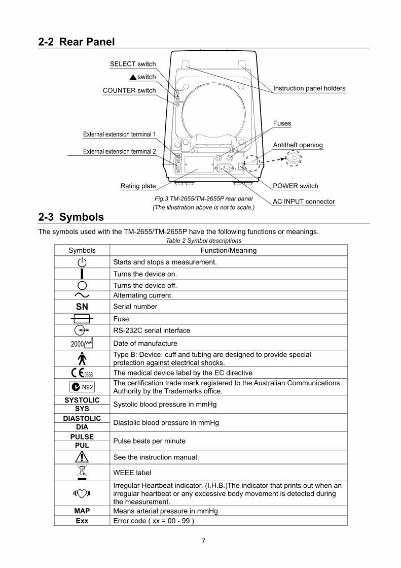
2-2 Rear Panel
Fig.3 TM-2655/TM-2655P rear panel (The illustration above is not to scale.)
2-3 Symbols The symbols used with the TM-2655/TM-2655P have the following functions or meanings.
Table 2 Symbol descriptions
Symbols Function/Meaning
Starts and stops a measurement.
Turns the device on.
Turns the device off. Alternating current
Serial number
Fuse
RS-232C serial interface
Date of manufacture
Type B: Device, cuff and tubing are designed to provide special protection against electrical shocks.
The medical device label by the EC directive
The certification trade mark registered to the Australian Communications Authority by the Trademarks office.
SYSTOLIC SYS Systolic blood pressure in mmHg
DIASTOLIC DIA Diastolic blood pressure in mmHg
PULSE PUL Pulse beats per minute
See the instruction manual.
WEEE label
Irregular Heartbeat indicator. (I.H.B.)The indicator that prints out when an irregular heartbeat or any excessive body movement is detected during the measurement.
MAP Means arterial pressure in mmHg Exx Error code ( xx = 00 - 99 )

8
What is An Irregular Heartbeat? The TM-2655P provides a blood pressure and pulse rate measurement even when an irregular heartbeat occurs. An irregular heartbeat is defined as a heartbeat that varies by 25% from the average of all heartbeats during the blood pressure measurement. It is important that you are relaxed, remain still and do not talk during measurements.
Note We recommend that a physician should examine the patient if the logo appears on the printout or request a second reading. It is possible for an Irregular Heartbeat ( ) to occur if a patient moves position or engages in conversation during a reading so care should be taken to eliminate the possibility of these events recurring.

9
3.INSTALLATION Follow the procedure below to install the TM-2655/TM-2655P.
1. To ensure that the TM-2655/TM-2655P works properly, install the device in an environment where:
The temperature range is from 10°C to 40°C (50°F to 104°F).
The humidity is less than 85% (non condensing).
It is away from water, dust, chemicals, and corrosive or explosive gases.
It is not exposed to direct sunlight.
2. Place the TM-2655/TM-2655P on a table solid enough to support its weight.
3. Adjust the height of the chair and table so that the arm insertion section is at the user’s heart level.
Fig.4 Proper installation
4. Use the power cable provided with the device to connect between the AC INPUT connector and an electrical outlet.
Using the anti-theft opening, secure the device to the table with a solid chain.
Fig.5 Power cable connection
Note Be sure to use the correct voltage for the power source.

10
4. OPERATION 1. Turn on the POWER switch located on the rear panel.
When the POWER switch is turned on, all of the display symbols will appear for several seconds. Then;
(TM-2655) “0” (zero) appears in the SYSTOLIC pressure display, indicating that the device is ready for measurement.
(TM-2655P) The human sensor functions for three minutes. When it does not detect a person, “ . “ (dot) appears in the SYSTOLIC pressure display, indicating that the device is ready for measurement.
Fig.6 POWER switch and Note SYSTOLIC display (TM-2566)
Please do not press the START/STOP switch when you turn on the power switch. Pressing and holding the START/STOP switch while all of the LED indicators are illuminated, will cause the device to enter the internal inspection mode.
2. Take off your jacket.
If you wear a thick jacket, take it off for a better measurement.
Note Wearing a thick jacket may cause a faint pulse, and result in a measurement error.
3. Adjust the height of the chair and table.
Adjust the height of the chair and table so that the arm insertion section is at your heart level.
4. Insert your arm into the arm insertion section.
Note Be sure to insert your arm to the shoulder.
5. Press the START/STOP switch to start measurement.
6. The cuff will be pressurized automatically up to the
predetermined pressure. Refer to “7-2 Description of the Functions” for details.
7. When pressurization is complete, the automatic exhaust mechanism will gradually reduce the pressure in the cuff. Just relax and remain still.
Fig.7 Proper posture
Fig.8 Measuring procedure
11
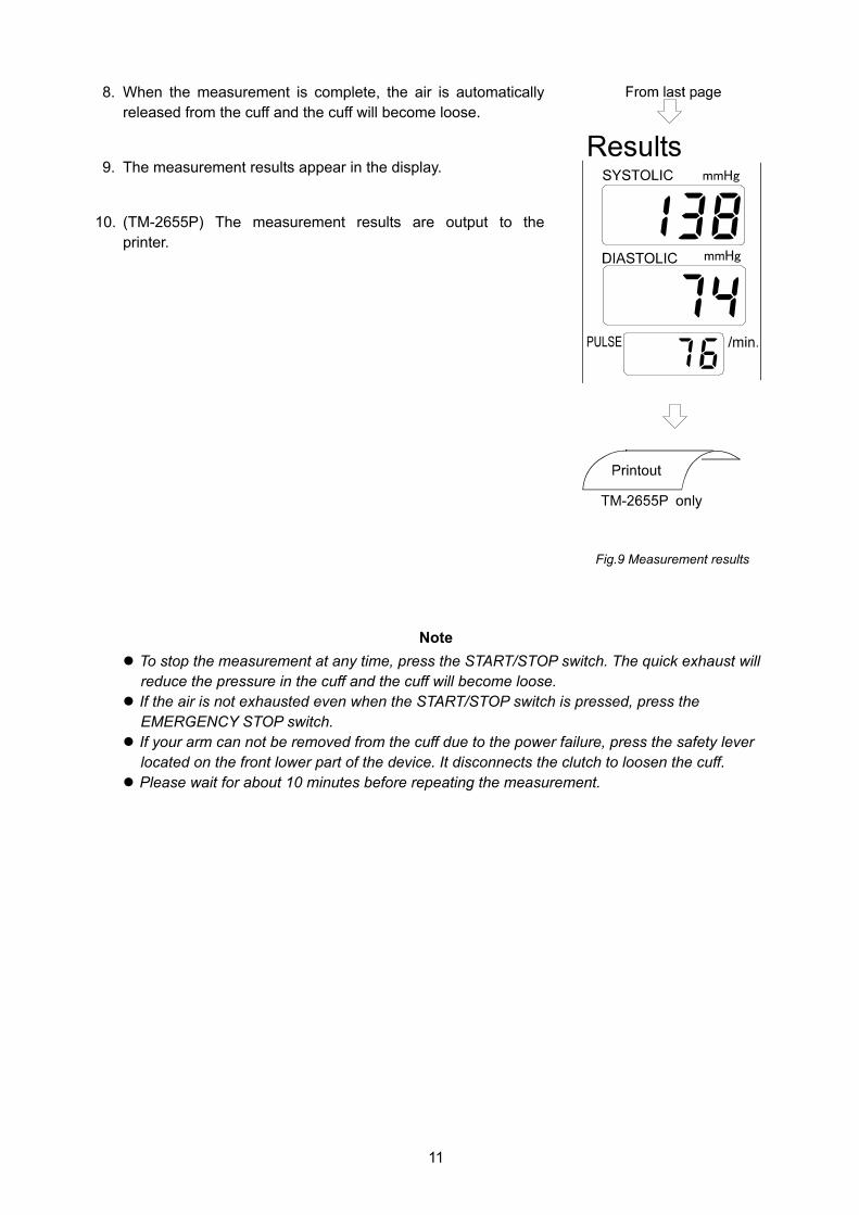
8. When the measurement is complete, the air is automatically released from the cuff and the cuff will become loose.
9. The measurement results appear in the display.
10. (TM-2655P) The measurement results are output to the printer.
Fig.9 Measurement results
Note To stop the measurement at any time, press the START/STOP switch. The quick exhaust will reduce the pressure in the cuff and the cuff will become loose.
If the air is not exhausted even when the START/STOP switch is pressed, press the EMERGENCY STOP switch.
If your arm can not be removed from the cuff due to the power failure, press the safety lever located on the front lower part of the device. It disconnects the clutch to loosen the cuff. Please wait for about 10 minutes before repeating the measurement.

12
5.SETTING THE CLOCK
5-1 Clock Adjustment Mode The clock is set in the clock adjustment mode. The clock adjustment mode display and switches used are
as shown below:
Fig.10 Switches for setting the clock and the clock adjustment mode display
Table 3 Switches for setting the clock
SELECT switch (1) Press to enter the clock adjustment mode.
(2) (In the clock adjustment mode) Press to select the unit to be adjusted. The selected unit flashes. Each time the switch is pressed, the flashing unit changes: from “Year” to “Month”, “Date”, “Hours”, and “Minutes”.
(3) Press to quit the clock adjustment mode.
switch Press to change the flashing digit(s).
5-2 A Setting Example The following is the procedure to adjust the clock to 14:07, April 20, 2001.
1. Press the SELECT switch to make the SYSTOLIC display flash.
2. Press the switch to display “01” for 2001.
3. Press the SELECT switch to make the DIASTOLIC display flash.
4. Press the switch to display “4” for April.
5. Press the SELECT switch to make the PULSE display flash.
6. Press the switch to display “20”.
7. Press the SELECT switch to make the hours section of the TIME display flash.

13
8. Press the switch to display “14”.
9. Press the SELECT switch to make the minutes section of the TIME display flash.
10. Press the switch to display “07”.
11. Press the SELECT switch to return to the measurement mode.
Note If no operation is performed for one minute, while setting the minutes section and for five seconds while setting the others, the settings performed so far will be confirmed and the device will return to the measurement mode.
The clock can be set up to December 31, 2091.

14
6. INSTALLING THE PRINTER PAPER (This chapter is applicable only to the TM-2655P.)
With the power turned on, install the printer paper as follows:
1. Cut the top end of the printer paper with scissors. If the end is not smooth, it may cause a paper jam or damage the printer head.
2. Press lightly on the center of the printer cover to open the cover.
3. Raise the lever located on the right side of the printer.
Set the lever to the up position (2) of the figure . The insertion of the printer paper is enabled.
4. Insert the printer paper into the paper feed slot as shown. The paper is fed automatically.
5. Press the PAPER FEED switch to feed the paper by about 10
cm. Confirm that the paper is fed straight. If not, re-install the paper because it may cause a paper jam.
Printer cover
Raise the lever to the up position (2) .
Lever
PAPER FEED switch
Paper feed slot
15
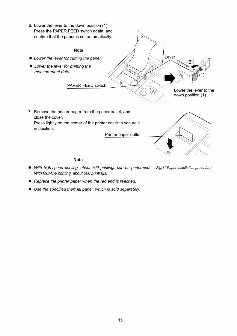
6. Lower the lever to the down position (1) . Press the PAPER FEED switch again, and confirm that the paper is cut automatically.
Note
Lower the lever for cutting the paper.
Lower the lever for printing the measurement data.
7. Remove the printer paper from the paper outlet, and close the cover. Press lightly on the center of the printer cover to secure it in position.
Note
With high-speed printing, about 700 printings can be performed. With four-line printing, about 500 printings.
Replace the printer paper when the red end is reached.
Use the specified thermal paper, which is sold separately.
Printer paper outlet
Lower the lever to the down position (1) .
Lever
PAPER FEED switch
Fig.11 Paper installation procedure

16
7. SETTING THE FUNCTIONS
7-1 Function Setting Mode The TM-2655/TM-2655P is provided with various functions, which allow the user to set the device to suit
the user’s requirements. The functions are set in the function setting mode. The function setting mode
display and switches used are as shown below:
Fig.12 Switches for setting the function and the function setting mode display
Table 4 Switches for setting the functions
switch and SELECT switch Hold down the switch and press the SELECT switch to enter the function setting mode.
COUNTER switch Press to select the function to set.
switch Press to select the function parameter.
1. Hold down the switch and press the SELECT switch. “f01” appears in the SYSTOLIC pressure
display. This indicates that the monitor is now in the function setting mode.
2. Press the COUNTER switch to select the function number to set. Each time the switch is pressed, the function number changes: from “f01” to “f02” to “f03”.
3 Press the switch to select the function parameter.
4. When the settings are complete, turn the power off and turn it on again. The settings are saved.

17
7-2 Description of the Functions Table 5 Functions
No. Function SYSTOLIC display
DIASTOLIC display
Description
F01 f01 off Not available.
off No printing
1 High-speed printing
2 4-line printing
3 4-line printing
4 Graph printing
F02 f02
5 Table printing
off No bit pattern printing F03
Printer setting
(See “7-3 Printing Samples” for what each method printing looks like.)
TM-2655P only f03
on Bit pattern printing
999 The results remain in the display unless another operation is performed.
5 Displays the results for 5 seconds.
10 Displays the results for 10 seconds.
F04 Displaying time f04
20 Displays the results for 20 seconds.
1 Terminals 1 and 2 to a PC
2 Terminal 1 to a PC Terminal 2 to a card reader
3 Terminal 1 to a scale Terminal 2 to a PC
F05 External connection
Ff05
4 N.A.
au Automatic pressurization
160 Pressurizes the cuff up to 160 mmHg.
180 Pressurizes the cuff up to 180 mmHg.
F06
Pressurization Ff06
200 Pressurizes the cuff up to 200 mmHg.
120 1200 bps
240 2400 bps
480 4800 bps
F07 Channel 1 baud rate
Ff07
960 9600 bps
120 1200 bps
240 2400 bps
480 4800 bps
F08 Channel 2 baud rate
Ff08
960 9600 bps
F09 Ff09 H9 Not available.
off Does not detect a human presence. F10 Human sensor Ff10
on Detects a human presence.
off Does not output the results automatically.
F11 Automatic external output
Ff11
on Outputs the results automatically.

18
7-3 Printing Samples
High-speed printing Graph printing
4-line printing
Table printing Bit pattern printing
Fig.13 Printing samples
Note
Bit pattern printing is available only for the TM-2655P. With this format, some items such as the company name can be printed. For details, contact your nearest dealer. When detecting an irregular heart beat(I.H.B), is printed.

19
8. COMMUNICATION SPECIFICATIONS The TM-2655/TM-2655P is equipped with two RS-232C channels. Various settings for each channel are available in the function setting mode. Refer to “7-2 Description of the Functions” for details.
8-1 Channel 1 : Miniature 8-pin DIN CAUTION
The personal computer and medical equipment connected to the device are not allowed to be in the patient area.
The personal computer used must conform to IEC60950
Specifications Table 6 Channel 1 specifications
Standard Conforms to EIA RS-232C Transmission Asynchronous, half-duplex Baud rate 1200, 2400, 4800, 9600 bps (Can be changed in the function setting mode “F07”.)Data bits 8 bits Parity bit None Stop bits 1 bit Code ASCII
Equipment available for connection
Channel 1: Scales, and automatic weight and height scales manufactured by A&D Channel 2: Personal computer
Pin assignment
Pin No. Signal name Description 1 TXD Send data 2 RXD Receive data 3 RTS Ready to send 4 - Used internally 5 CTS Clear to send 6 GND Signal ground 7 - Used internally 8 - Used internally
Fig.14 Pin assignment Cable connection between the device and a personal computer TM-2655/TM-2655P Personal computer
Fig.15 Cable connection diagram
Note Do not use pins 4, 7, and 8. They are used by the device.

20
8-2 Channel 2: D-sub 9-pin CAUTION
The personal computer and medical equipment connected to the device are not allowed to be in the patient area.
The personal computer used must conform to IEC60950
Specifications Table 7 Channel 2 specifications
Standard Conforms to EIA RS-232C Transmission Asynchronous, half-duplex Baud rate 1200, 2400, 4800, 9600 bps (Can be changed in the function setting mode “F08”.)Data bits 8 bits Parity bit None Stop bits 1 bit Code ASCII
Equipment available for connection Channel 1: Personal computer Channel 2: Card reader
Pin assignment Pin No. Signal name Direction Description
1 - - - 2 RXD In Receive data 3 TXD Out Send data 4 DTR Out Data terminal ready 5 GND - Signal ground 6 DSR In Data set ready 7 RTS Out Ready to send 8 CTS In Clear to send 9 - - -
Fig.16 Pin assignment
Cable connection between the device and a personal computer TM-2655/TM-2655P Personal computer
Fig.17 Cable connection diagram
Note The protocol depends on the equipment connected.

21
9. MAINTENANCE
9-1 Replacing the Arm Cuff Cover Replace the arm cuff cover as follows:
1. Locate the cover at the bottom of the arm insertion section. Slide the cover downward to open it. A screw is exposed.
Using the screwdriver, loosen the screw and remove the front frame.
2. Remove the four screws on the rear panel to remove the armrest and the rear panel.
3. Remove the front vinyl ring of the arm cuff cover from the groove. Remove the rear vinyl ring of the arm cuff cover from the groove. Pull out the arm cuff cover.
Note The vinyl rings will be used to support the new arm cuff cover.
4. Place a new arm cuff cover in the arm cuff area. Secure the front and rear vinyl rings of the arm cuff cover in the groove. Smooth the cover cloth near the grooves.
5. Replace the rear panel, the armrest, and the front frame in the reversed order of removal. Slide the cover upward to secure it in position.
Note The arm cuff cover is a consumable. Purchase it separately. Remove the vinyl rings from the old arm cuff and install them in the new arm cuff cover. The vinyl rings are not included with the optional arm cuff cover.
Fig.18 Arm cuff replacing procedure

22
9-2 Replacing the Fuses
Replace the fuses as follows: 1. Remove the caps of both fuse holders located on the rear
panel.
2. Replace both fuses with new ones.
3. Re-install the fuse holder caps.
Fig.19 Fuse holders
Note Use only fuses of the proper type, voltage and current rating as specified on the rear panel, and that conform to IEC60127.
9-3 Checking the Counter
The TM-2655/TM-2655P is equipped with a counter function, which indicates how many times the device
has measured blood pressure. The counter data remains in memory even after the power is turned off.
Use the counter function to check the frequency of the device use or as the guideline for a periodic
cleaning Displaying the counter Press the COUNTER switch. The counter data appears in the
SYSTOLIC and DIASTOLIC displays for about 5 seconds.
Note Do not keep the COUNTER switch pressed. It will reset the counter data to zero. Ex. The measurement count at the figure is 2382 times.
The number of more than 1000 is displayed.
The number of less than 1000 is displayed.
The symbol is displayed at checking the counter.

23
Resetting the counter Hold down the COUNTER switch for 4 seconds or more.
The counter data will be reset to zero.
Printing the counter graph Press and hold the COUNTER switch, press the PAPER FEED
switch to display the current measurement count. Total : The total measurement count of the product.
Weekly Count : The count for last one week.
Monthly Count : The count for last one year. Note1:The Total can not be reset by pressing the COUNTER switch.
Note2:When the print selection is "OFF", the counter graph is not printed.
9-4 Error Codes Table 9 Error codes
Error code Description
pe The printer paper has run out. Install a new roll of printer paper.
HU The printer head is up. Lower the lever and lock the printer paper in position.
err A measurement error has occurred. Refer to “10. Troubleshooting”.
9-5 Maintenance Do not open the device. It uses delicate electronic components and an intricate air unit that could be damaged.
If you can not fix the problem using the troubleshooting instructions, request service from your supplier or from
the A&D service group. The A&D service group will provide technical information, spare parts and units to
authorized suppliers.
The technical testing procedures, which should be done at least every two years, can be performed either by
the manufacturer or by an authorized repair service in accordance with the regulations governing
manufacturing of medical products.
9-6 Cleaning
CAUTION Never immerse the TM-2655/TM-2655P in water for cleaning, that may damage the electronic
parts inside.
Never use thinner or a strong detergent for cleaning, that may discolor or deform the plastic case and display panel.
Fig.20 COUNTER switch

24
Housing case Clean the case gently using a soft cloth moistened with water and mild detergent or alcohol.
Display panel Clean the display gently so as not to scratch the panel surface. Use a soft cloth moistened with water.
Arm cuff cover When the arm cuff cover becomes dirty or it is worn out, replace with a new one. Refer to “9-1 Replacing the Arm Cuff Cover”.
Note
If the cover is not installed properly, it may cause problems in operation.
9-7 Options and Consumables Options and consumables available for the TM-2655/TM-2655P are shown below. Order them from the
nearest dealer. Use the part numbers when ordering.
Table ·····································································TM-9325
Chair without backrest (Gas shock suspension)···TM-9312A
Chair with backrest (Gas shock suspension)········TM-9315A
Printer paper (5 rolls) ··········································· AX-PP147-S
Arm cuff cover ··························································AX-133003442-S
Power cable (cord set) ·············································AX-KO243 (Type C)
Power cable (cord set) ·············································AX-KO242 (Type BF)
Power cable (cord set) ·············································AX-KO115 (Type A)
25
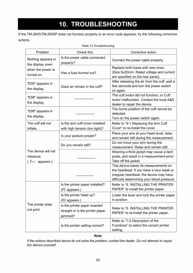
10. TROUBLESHOOTING If the TM-2655/TM-2655P does not function properly or an error code appears, try the following corrective
actions. Table 10 Troubleshooting
Problem Check this Corrective action Is the power cable connected properly?
Connect the power cable properly. Nothing appears in the display, even when the power is turned on. Has a fuse burned out?
Replace both fuses with new ones. (Size 5x20mm. Rated voltage and current are specified on the rear panel).
"E00" appears in the display. Does air remain in the cuff?
After releasing the air from the cuff, wait a few seconds and turn the power switch on again.
"E98" appears in the display.
The cuff motor did not function, or Cuff motor malfunction. Contact the local A&D dealer to repair the device.
"E99" appears in the display.
The home position of the cuff cannot be detected. Turn on the power switch again.
The cuff will not inflate.
Is the arm cuff cover installed with high tension (too tight)?
Refer to “9-1 Replacing the Arm Cuff Cover” to re-install the cover.
Is your posture proper? Place your arm at your heart level, relax and remain still during the measurement.
Do you remain still? Do not move your arm during the measurement. Relax and remain still.
Wearing a thick jacket may cause a faint pulse, and result in a measurement error. Take off the jacket.
The device will not measure. (Eerr appears.)
This device bases its measurements on the heartbeat. If you have a very weak or irregular heartbeat, the device may have difficulty determining your blood pressure.
Is the printer paper installed? (pe appears.)
Refer to “6. INSTALLING THE PRINTER PAPER” to install the printer paper.
Is the printer head up? (HU appears.)
Lower the lever and lock the printer paper in position
Is the printer paper inserted straight or is the printer paper jammed?
Refer to “6. INSTALLING THE PRINTER PAPER” to re-install the printer paper.
The printer does not print.
Is the printer setting correct? Refer to “7-2 Description of the Functions” to select the correct printer setting.
Note If the actions described above do not solve the problem, contact the dealer. Do not attempt to repair the device yourself.

26
11. EXTERNAL DIMENSIONS
Fig.20 External dimensions
Note The illustration above indicates the TM-2655P with the printer unit. The dimensions are the same for the TM-2655 and TM-2655P.
27
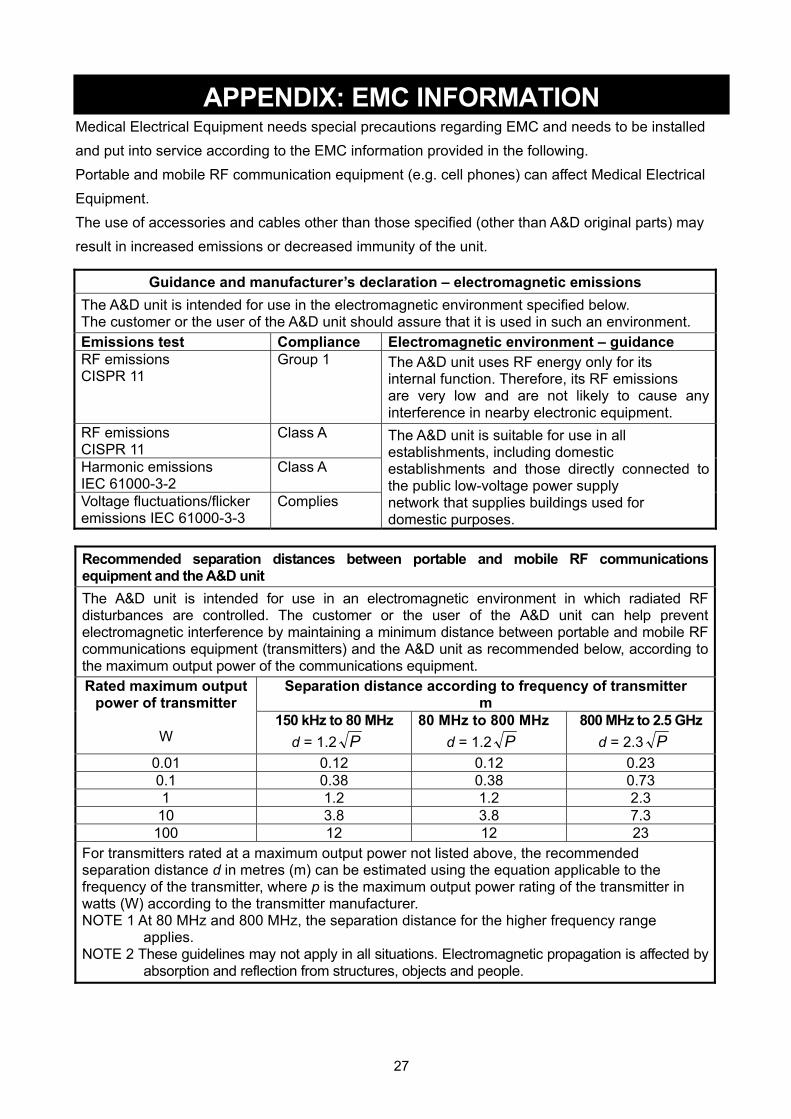
APPENDIX: EMC INFORMATION Medical Electrical Equipment needs special precautions regarding EMC and needs to be installed and put into service according to the EMC information provided in the following. Portable and mobile RF communication equipment (e.g. cell phones) can affect Medical Electrical Equipment. The use of accessories and cables other than those specified (other than A&D original parts) may result in increased emissions or decreased immunity of the unit.
Guidance and manufacturer’s declaration – electromagnetic emissions The A&D unit is intended for use in the electromagnetic environment specified below. The customer or the user of the A&D unit should assure that it is used in such an environment. Emissions test Compliance Electromagnetic environment – guidance RF emissions CISPR 11
Group 1 The A&D unit uses RF energy only for its internal function. Therefore, its RF emissions are very low and are not likely to cause any interference in nearby electronic equipment.
RF emissions CISPR 11
Class A
Harmonic emissions IEC 61000-3-2
Class A
Voltage fluctuations/flicker emissions IEC 61000-3-3
Complies
The A&D unit is suitable for use in all establishments, including domestic establishments and those directly connected to the public low-voltage power supply network that supplies buildings used for domestic purposes.
Recommended separation distances between portable and mobile RF communications equipment and the A&D unit The A&D unit is intended for use in an electromagnetic environment in which radiated RF disturbances are controlled. The customer or the user of the A&D unit can help prevent electromagnetic interference by maintaining a minimum distance between portable and mobile RF communications equipment (transmitters) and the A&D unit as recommended below, according to the maximum output power of the communications equipment.
Separation distance according to frequency of transmitter m
Rated maximum output power of transmitter
W
150 kHz to 80 MHz d = 1.2 P
80 MHz to 800 MHz d = 1.2 P
800 MHz to 2.5 GHz d = 2.3 P
0.01 0.12 0.12 0.23 0.1 0.38 0.38 0.73 1 1.2 1.2 2.3
10 3.8 3.8 7.3 100 12 12 23
For transmitters rated at a maximum output power not listed above, the recommended separation distance d in metres (m) can be estimated using the equation applicable to the frequency of the transmitter, where p is the maximum output power rating of the transmitter in watts (W) according to the transmitter manufacturer. NOTE 1 At 80 MHz and 800 MHz, the separation distance for the higher frequency range
applies. NOTE 2 These guidelines may not apply in all situations. Electromagnetic propagation is affected by
absorption and reflection from structures, objects and people.
28
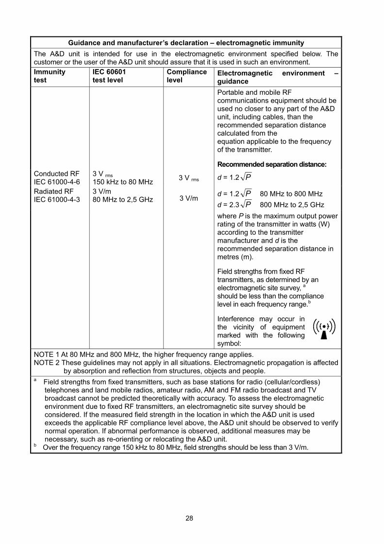
Guidance and manufacturer’s declaration – electromagnetic immunity The A&D unit is intended for use in the electromagnetic environment specified below. The customer or the user of the A&D unit should assure that it is used in such an environment. Immunity test
IEC 60601 test level
Compliance level
Electromagnetic environment – guidance
Portable and mobile RF communications equipment should be used no closer to any part of the A&D unit, including cables, than the recommended separation distance calculated from the equation applicable to the frequency of the transmitter. Recommended separation distance:
Conducted RF IEC 61000-4-6
3 V rms 150 kHz to 80 MHz 3 V rms d = 1.2 P
Radiated RF IEC 61000-4-3
3 V/m 80 MHz to 2,5 GHz 3 V/m d = 1.2 P 80 MHz to 800 MHz
d = 2.3 P 800 MHz to 2,5 GHz where P is the maximum output power
rating of the transmitter in watts (W) according to the transmitter manufacturer and d is the recommended separation distance in metres (m). Field strengths from fixed RF transmitters, as determined by an electromagnetic site survey, a should be less than the compliance level in each frequency range.b Interference may occur in the vicinity of equipment marked with the following symbol:
NOTE 1 At 80 MHz and 800 MHz, the higher frequency range applies. NOTE 2 These guidelines may not apply in all situations. Electromagnetic propagation is affected
by absorption and reflection from structures, objects and people. a Field strengths from fixed transmitters, such as base stations for radio (cellular/cordless)
telephones and land mobile radios, amateur radio, AM and FM radio broadcast and TV broadcast cannot be predicted theoretically with accuracy. To assess the electromagnetic environment due to fixed RF transmitters, an electromagnetic site survey should be considered. If the measured field strength in the location in which the A&D unit is used exceeds the applicable RF compliance level above, the A&D unit should be observed to verify normal operation. If abnormal performance is observed, additional measures may be necessary, such as re-orienting or relocating the A&D unit.
b Over the frequency range 150 kHz to 80 MHz, field strengths should be less than 3 V/m.
29
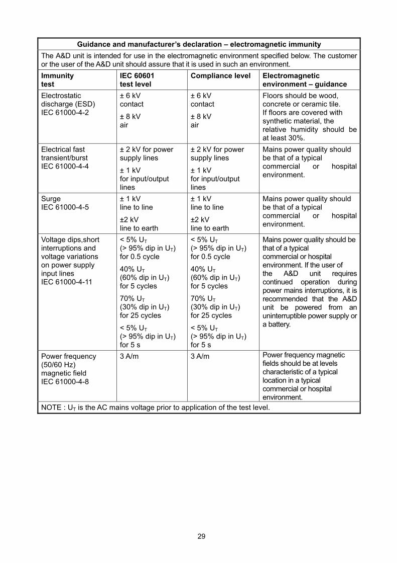
Guidance and manufacturer’s declaration – electromagnetic immunity The A&D unit is intended for use in the electromagnetic environment specified below. The customer or the user of the A&D unit should assure that it is used in such an environment. Immunity test
IEC 60601 test level
Compliance level Electromagnetic environment – guidance
Electrostatic discharge (ESD) IEC 61000-4-2
± 6 kV contact
± 8 kV air
± 6 kV contact
± 8 kV air
Floors should be wood, concrete or ceramic tile. If floors are covered with synthetic material, the relative humidity should be at least 30%.
Electrical fast transient/burst IEC 61000-4-4
± 2 kV for power supply lines
± 1 kV for input/output lines
± 2 kV for power supply lines
± 1 kV for input/output lines
Mains power quality should be that of a typical commercial or hospital environment.
Surge IEC 61000-4-5
± 1 kV line to line
±2 kV line to earth
± 1 kV line to line
±2 kV line to earth
Mains power quality should be that of a typical commercial or hospital environment.
Voltage dips,short interruptions and voltage variations on power supply input lines IEC 61000-4-11
< 5% UT (> 95% dip in UT) for 0.5 cycle
40% UT (60% dip in UT) for 5 cycles
70% UT (30% dip in UT) for 25 cycles
< 5% UT (> 95% dip in UT) for 5 s
< 5% UT (> 95% dip in UT) for 0.5 cycle
40% UT (60% dip in UT) for 5 cycles
70% UT (30% dip in UT) for 25 cycles
< 5% UT (> 95% dip in UT) for 5 s
Mains power quality should be that of a typical commercial or hospital environment. If the user of the A&D unit requires continued operation during power mains interruptions, it is recommended that the A&D unit be powered from an uninterruptible power supply or a battery.
Power frequency (50/60 Hz) magnetic field IEC 61000-4-8
3 A/m 3 A/m Power frequency magnetic fields should be at levels characteristic of a typical location in a typical commercial or hospital environment.
NOTE : UT is the AC mains voltage prior to application of the test level.

30
MEMO

31
MEMO

32
MEMO

13

1-243 Asahi , Kitamoto-shi, Saitama 364-8585, JAPAN Telephone: [81] (48) 593-1111 Fax: [81] (48) 593-1119 A&D INSTRUMENTS LIMITED Unit 24/26 Blacklands Way, Abingdon Business Park, Abingdon, Oxfordshire OX14 1DY United Kingdom Telephone: [44] (1235) 550420 Fax: [44] (1235) 550485 A&D ENGINEERING, INC. 1756 Automation Parkway, San Jose, California 95131, U.S.A. Telephone: [1] (408) 263-5333 Fax: [1] (408)263-0119 A&D AUSTRALASIA PTY LTD 32 Dew Street, Thebarton, South Australia 5031, AUSTRALIA Telephone: [61] (8) 8301-8100 Fax: [61] (8) 8352-7409 OOO A&D RUS OOO "ЭЙ энд ДИ РУС" 121357, Российская Федерация, г.Москва, ул. Верейская, дом 17 ( Business-Center "Vereyskaya Plaza-2" 121357, Russian Federation, Moscow, Vereyskaya Street 17 ) тел.: [7] (495) 937-33-44 факс: [7] (495) 937-55-66 A&D Technology Trading(Shanghai) Co. Ltd 爱安德技研贸易(上海)有限公司 中国 上海市浦东新区浦东大道138号永华大厦21楼A室 邮编200120
( 21F Room A, Majesty Building, No.138 Pudong Avenue, Pudong New Area, Shanghai, 200120, China ) 电话: [86] (21) 3393-2340 传真: [86] (21) 3393-2347