Embed Size (px)
Citation preview
Automatic and DDC Control Fundamentals
and Energy Conservation for
HVAC Equipment-Part 1
1-1

DisclaimerDisclaimerThis presentation was prepared specifically for use as
college training material It shall not be modifiedcollege training material. It shall not be modified without the consent of the authors.
This presentation represents sponsored research activities. Neither the Client nor Battelle warrantsactivities. Neither the Client nor Battelle warrants the accuracy, completeness or usefulness of the information. Reference herein to any specific
i l d t i b t dcommercial product, process or service by trade names or manufacturer does not constitute an endorsement or recommendation.
1-2PNWD-SA-8834

DDC Controls and Energy Conservation for HVAC Eq ipment AgendaHVAC Equipment - Agenda
1. Introduction of DDC Controls Project2 HVAC C t l P i i l2. HVAC Control Principles3. Communication Standards and Networks4 Vendor Examples of DDC Software Programming and4. Vendor Examples of DDC Software Programming and
Operator Interfacing5. Typical Rooftop and Central AHU HVAC Control
Systems and ApplicationsSystems and Applications6. System Maintenance and Service of DDC Controls7. Avoiding Common Control Problems and Fixing the g g
Problems8. Calibrating and Verifying Energy Savings of the DDC
Controls
1-3PNWD-SA-8834

Part 1HVAC Control PrinciplesHVAC Control Principles
1. Intent of Battelle Pacific NW Division involvement2. Purpose of Controls 3. Key Components of Control Systemsy p y4. Control Loops, Open vs. Closed Loops5 Terminology5. Terminology6. The Control Cycle and Control Actions7 Th E S f C t l S t7. The Energy Sources for Control Systems8. DDC Point Types
1-4PNWD-SA-8834
Part 2Control Applications, Networks, Programming, Maintenance, and Energy SavingsEnergy Savings1. DDC Control Applications2. DDC Networks and Architecture3. Communication Standards and Networks4. Vendor Examples of DDC Software Programming
and Operator Interfacing5. System maintenance and service of DDC controls6. Using DDC controls to save energy
1-5PNWD-SA-8834
g gy

Section 1Introduction of DDC Controls Project• Purpose of this project is to provide HVAC
d ti l t i l t W hi t St teducational materials to Washington State community colleges to educate students who have chosen or may chose career paths related to HVACchosen or may chose career paths related to HVAC servicing and building energy management fields
1-6PNWD-SA-8834

Section 2HVAC Control PrinciplesHVAC Control PrinciplesThe Purpose of Temperature Controls• Control systems are the “brains” of HVAC equipment to
i t i h f t Pi t d b l i AHU th tmaintain human comfort. Pictured below is an AHU that serves only one zone. This type of AHU is called a single zone AHU. In the example, a temperature sensor (stat) sends
i l t t l l hi h d i l t la signal to a control panel, which sends a signal to a valve.
1-7PNWD-SA-8834
Courtesy TAC Controls/Schneider Electric

Section 3K C t f C t l Key Components of a Control System Include:
1-8PNWD-SA-8834
Courtesy TAC Controls/Schneider Electric

Sensors Modern HVAC Sensors Include:• Humidity and temperature transmitters • CO2 for indoor air quality (IAQ) utilizing
d d t l til tidemand control ventilation• Power meters• Branch circuit monitors• Branch circuit monitors• Energy meters
1-9PNWD-SA-8834
Courtesy Veris Industries

Sensors• A sensor monitors and measures a variable. The
HVAC variables are temperature, humidity, flow, and pressure Different types of signals are produced bypressure. Different types of signals are produced by different types of sensors. They include:–Electric sensorsElectric sensors–Pneumatic sensors
Electronic sensors–Electronic sensors
An example of a sensor is shown here. While it may appear to be a thermostat, it is a remote sensor with a remote setpoint dial The controller is in another
1-10PNWD-SA-8834
a remote setpoint dial. The controller is in another location.
Courtesy TAC Controls/Schneider Electric
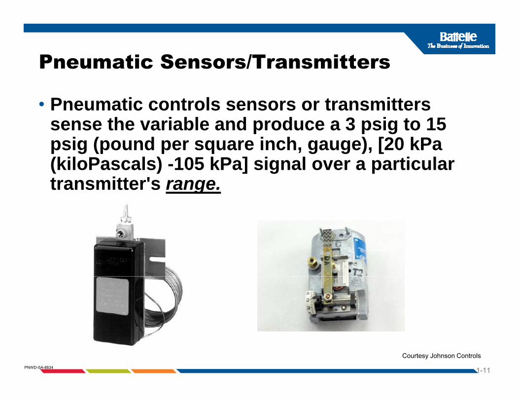
Pneumatic Sensors/Transmitters
• Pneumatic controls sensors or transmitters sense the variable and produce a 3 psig to 15sense the variable and produce a 3 psig to 15 psig (pound per square inch, gauge), [20 kPa (kiloPascals) -105 kPa] signal over a particular transmitter's range.
1-11PNWD-SA-8834
Courtesy Johnson Controls
Electronic Sensors Include:
• Resistance sensors are resistance temperature devices (RTDs) and are used in measuringdevices (RTDs), and are used in measuring temperature. Examples are Balco elements, copper platinum, 10K thermistors, and 30K thermistors.
• Voltage sensors could be used for temperature, humidity and pressure. Typical ranges are 0 to 5 Vd (V lt di t t) 1 t 11 Vd d 0 t 10Vdc (Volts direct current), 1 to 11 Vdc, and 0 to 10 Vdc. C t ld b d f t t• Current sensors could be used for temperature, humidity, and pressure. The typical current range is 4 to 20 mA (milliamps).
1-12PNWD-SA-8834
( p )

1000Ω (Ohms) Balco PTC Electronic Temperature SensorsElectronic Temperature Sensors• The resistance outputs of a electronic Balco temperature
sensor follow the diagrams below:
• When 1000 ohms is measured across the Balco element, the temperature is approximately 70°F (21°C) As the temperaturetemperature is approximately 70°F (21°C). As the temperature increases, the resistance changes 2.2 ohms per 1°F (3.96 ohms per 1°C). In a Balco temperature sensor, as the t t i th i t i ti lltemperature increases, the resistance increases proportionally in a positive direction. This is known as a positive temperature coefficient (PTC) sensor. However, many temperature sensors
id d th i t d f N ti
1-13PNWD-SA-8834
are considered thermistors, and perform as Negative temperature coefficients (NTC).

Comparison of Common Temp Sensorsp p
1-14PNWD-SA-8834
Courtesy Omega Controls

Controllers Can Include:Electric Controls Pneumatic Controls
DDCControls
1-15PNWD-SA-8834
Electronic ControlsCourtesy Johnson, Honeywell, and Alerton Controls

Controllers basic principlesthe controller receives the input And processes an output
1-16PNWD-SA-8834
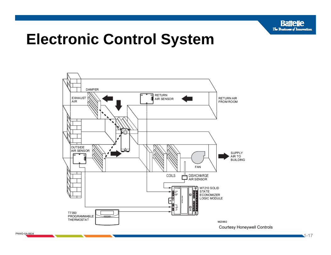
Electronic Control Systemy
1-17PNWD-SA-8834
Courtesy Honeywell Controls

Pneumatic Controller SystemPneumatic Controller System
“Branch” or Control Damper“Branch” or Control Damper
Sensor
Branch or Control Pressure
Damper
Sensor
Branch or Control Pressure
DamperController Operator
Filter“Main” or Supply
Controller Operator
Filter“Main” or Supply
PressureRegulator
pp yPressure
CompressorPressureRegulator
pp yPressure
Compressor
ThermostatValve
Actuator ThermostatValve
Actuator
1-18PNWD-SA-8834
ValveValve
Courtesy Northwest Energy Efficiency Council
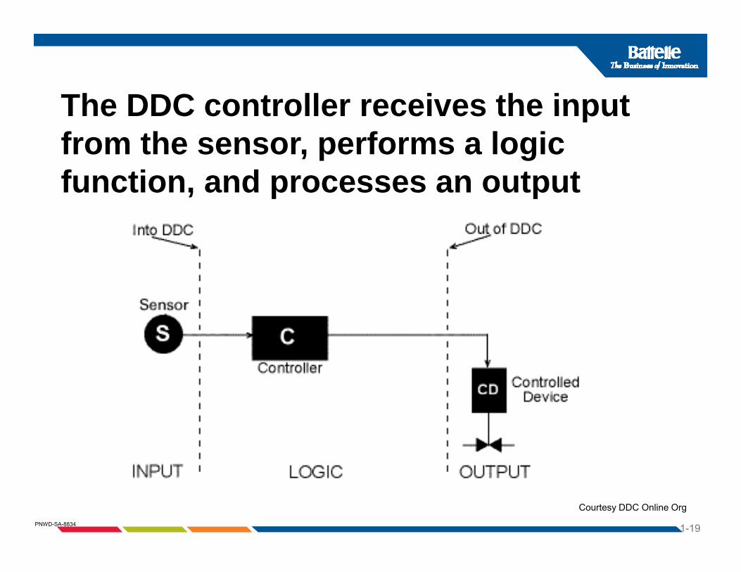
The DDC controller receives the inputThe DDC controller receives the inputfrom the sensor, performs a logic function and processes an outputfunction, and processes an output
1-19PNWD-SA-8834
Courtesy DDC Online Org

Controller Action-Direct or ReverseIllustration
1-20PNWD-SA-8834
Courtesy Honeywell Controls

Controller Direct Action-Illustration
1-21PNWD-SA-8834
Courtesy TAC Controls/Schneider Electric

Controller Direct Action-Illustration
• This relationship between the input to a controller (temperature) and its output (current) can be(temperature) and its output (current) can be displayed on a graph as follows:
1-22PNWD-SA-8834
Courtesy TAC Controls/Schneider Electric

Controller Reverse Action-IllustrationController Reverse Action Illustration
1-23PNWD-SA-8834
Courtesy TAC Controls/Schneider Electric

Controller Reverse Action-IllustrationController Reverse Action Illustration• This relationship can is displayed on a graph as
follows:follows:
1-24PNWD-SA-8834
Courtesy TAC Controls/Schneider Electric

Controlled DevicesControlled Devices
Control ValvesControl Valves– two-way Control Valves
Used with differential pressure (DP) sensors and VSD pump systems on primary and secondary loops
– three-way (mixing or diverting)Press re independent control al es– Pressure independent control valves
Automatic dampersAutomatic dampersDamper operatorsVSDs: variable speed drives
1-25PNWD-SA-8834
VSDs: variable speed drives
Courtesy Belimo

Controlled DevicesValves
Mixing ValveDiverting Valve
g
T i l Th W Mi i
1-26PNWD-SA-8834
Typical Three-Way Mixing and Diverting Valves
Typical Single - and Double-SeatedTwo-Way Valves
Courtesy Belimo

The Present Control Systems
•Pressure independent control valves
yUse control valves that are:
Pressure independent control valves•No Cv required, reduced pumping costs, higher efficiency, easy to balance.
1-27PNWD-SA-8834
Courtesy Flow Control Valves
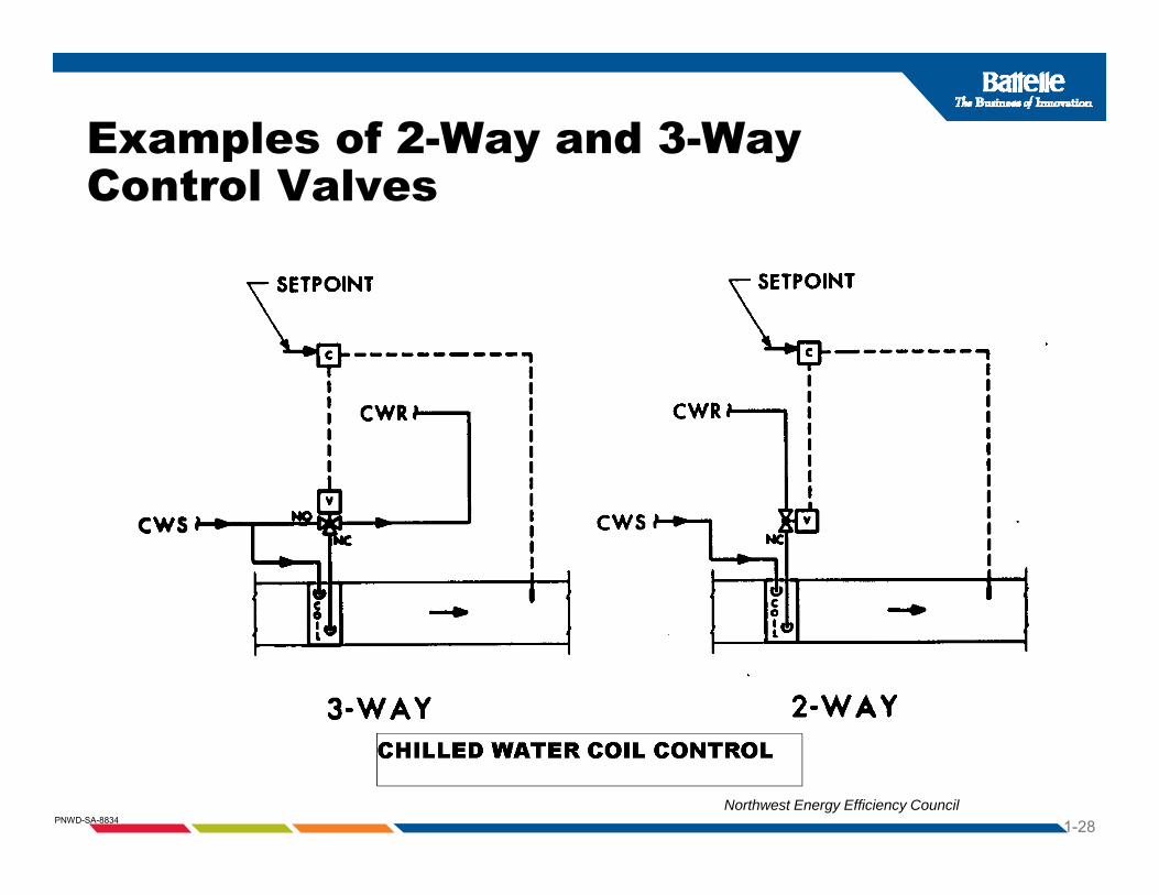
Examples of 2-Way and 3-Way Control Valves
1-28PNWD-SA-8834Northwest Energy Efficiency Council

Dampers: Types, Actuators, and Characteristicsand Characteristics
– Economizers on many central AHUs are custom ordered for the job specific custo o de ed o t e job spec crequirements
– Economizers on packaged RTUs are normally ordered as an option with thenormally ordered as an option with the package
– Control Dampers Can Be Either:P ll l d dParallel or opposed dampers
1-29PNWD-SA-8834
Parallel Blade Opposed Blade

Economizer Damper Actuator Typesare either:
Electric ElectronicPneumatic Electric ElectronicPneumatic
1-30PNWD-SA-8834
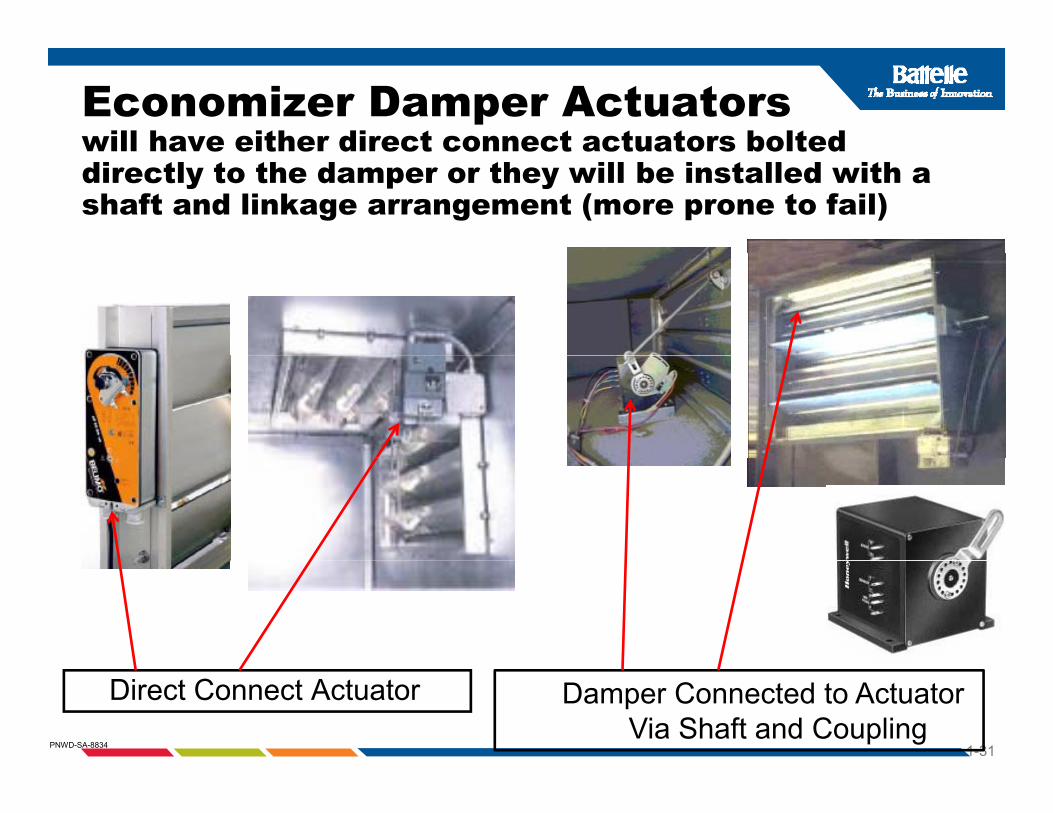
Economizer Damper Actuatorswill have either direct connect actuators bolted will have either direct connect actuators bolted directly to the damper or they will be installed with a shaft and linkage arrangement (more prone to fail)
1-31PNWD-SA-8834
Direct Connect Actuator Damper Connected to Actuator Via Shaft and Coupling

Parallel Blade Damper Characteristicshave poor linear controlp
1-32PNWD-SA-8834
Courtesy T.A. & Co.

Opposed Damper Characteristicshave better linear control
1-33PNWD-SA-8834
Courtesy T.A. & Co.
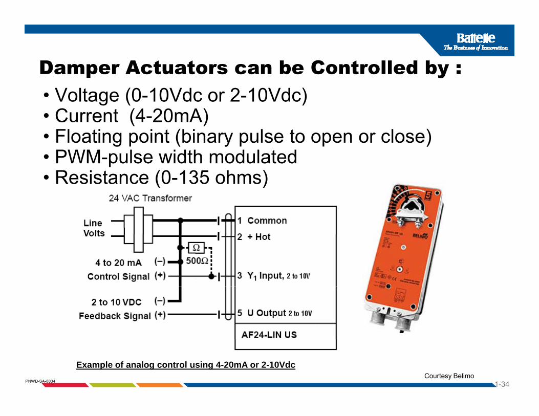
Damper Actuators can be Controlled by :p y• Voltage (0-10Vdc or 2-10Vdc) • Current (4-20mA)
Fl ti i t (bi l t l )• Floating point (binary pulse to open or close)• PWM-pulse width modulated• Resistance (0-135 ohms)Resistance (0 135 ohms)
1-34PNWD-SA-8834
Example of analog control using 4-20mA or 2-10VdcCourtesy Belimo

Electronic Variable F D i (VSD )Frequency Drives (VSDs)
•Vary frequency of motor to control speed
•Often called VSDs VFDs or ASDs•Often called VSDs, VFDs, or ASDs
1-35PNWD-SA-8834

DDC control systems have variable f ( )frequency drives (VFDs) asstandard equipment on:
C li• Cooling towers• AHU’s and VAV fans• Pumps • Chillers
1-36PNWD-SA-8834

Variable Speed DrivesVariable Speed Drives
1-37PNWD-SA-8834
Courtesy ABB Controls

Review of the Key Control Components Components Exercise-identify the sensors, controllers, and controlled devices
1-38PNWD-SA-8834
Courtesy TAC Controls/Schneider Electric

Review of the Key Control yComponents Exercise-connect the sensor, controller, and controlled device in the proper ordercontrolled device in the proper order.
1-39PNWD-SA-8834
Courtesy Alerton and Belimo

Review of Control ActionExercise the control drawing below has a Exercise-the control drawing below has a direct acting controller, with a NO valve. Show the correct action with arrows at each
t h d f li dcomponent when used for cooling mode.
___________Acting
1-40PNWD-SA-8834
Courtesy TAC Controls/Schneider Electric and Belimo

Review of Control ActionExercise-Circle the correct answer.
1-41PNWD-SA-8834
Courtesy TAC Controls/Schneider Electric
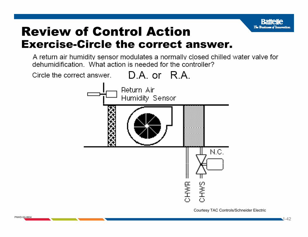
Review of Control ActionExercise Circle the correct answerExercise-Circle the correct answer.
1-42PNWD-SA-8834
Courtesy TAC Controls/Schneider Electric

Review of Control ActionExercise-Circle the correct answer.
1-43PNWD-SA-8834
Courtesy TAC Controls/Schneider Electric

Review of the Key Control Components Components Exercise-Identify the parallel vs. opposed blade dampers and the 3-way mixing vs. diverting
1-44PNWD-SA-8834
Courtesy Belimo
_________________
_________________ _________________
_________________

Section 4Section 4Basic Control Loop Principles
Controllers can be either
“ l d” “ ” L
Cl l id f db k d l
“closed” or “open” Loop
–Closes loops provide feedback-good control–Open loops have no feedback-poor control
1-45PNWD-SA-8834

Basic Closed-Loop-ExampleThe sensor feeds back to the controller
1-46PNWD-SA-8834
Courtesy DDC Online Org

Open Loop Controlshave no feedback to the controller
1-47PNWD-SA-8834
Courtesy DDC Online Org

Closed vs. Open Loop ControlIllustrationNotice, averaging bulb is closed loop in supply air, but T-STAT between filter and coil is open loop.
1-48PNWD-SA-8834
Courtesy Northwest Energy Efficiency Council
Section 5Control Terminology
Setpoint, offset, and control pointSetpoint, offset, and control pointThrottling rangeSpan and rangep gAuthorityCalibrationAnalog and digitalThermostat as sensor-controller
1-49PNWD-SA-8834
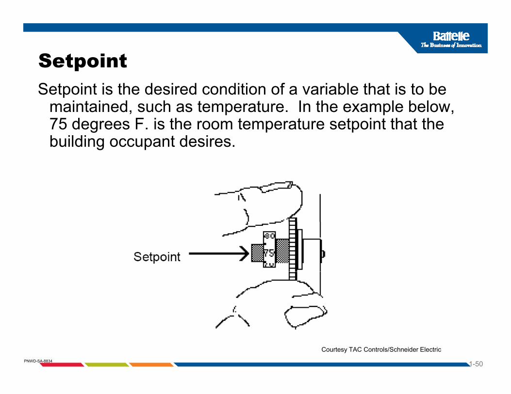
SetpointSetpoint is the desired condition of a variable that is to be
maintained, such as temperature. In the example below, 75 degrees F is the room temperature setpoint that the75 degrees F. is the room temperature setpoint that the building occupant desires.
1-50PNWD-SA-8834
Courtesy TAC Controls/Schneider Electric

Control Point and Offset• The Control point is the actual temperature being sensed.
The control point (temperature) may not be on the setpoint, but instead may be above or below it. Simply stated,but instead may be above or below it. Simply stated, setpoint is what you want, while control point is what you get. Offset is the amount of difference between control point and setpoint in a proportional control system In thepoint and setpoint in a proportional control system. In the example below, the offset is approximately 4°F.
1-51PNWD-SA-8834
Courtesy TAC Controls/Schneider Electric
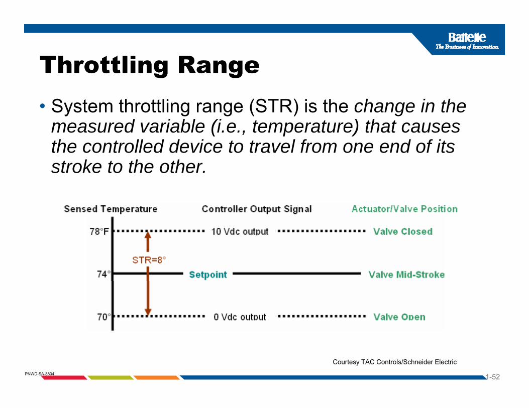
Throttling Range g g• System throttling range (STR) is the change in the
measured variable (i e temperature) that causesmeasured variable (i.e., temperature) that causes the controlled device to travel from one end of its stroke to the other.
1-52PNWD-SA-8834
Courtesy TAC Controls/Schneider Electric

Section 6
T iti
The Control Cycle and Control Action
•Two position•Floating action•Proportional action•PIPI•PID
1-53PNWD-SA-8834
Courtesy PECI
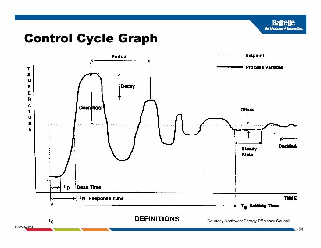
Control Cycle Graph
1-54PNWD-SA-8834
Courtesy Northwest Energy Efficiency Council

T P iti C t lTwo Position Control
1-55PNWD-SA-8834
Two Position control action chart (heating action shown)
Courtesy Northwest Energy Efficiency Council

T P iti C t l RTwo Position Control Response
1-56PNWD-SA-8834
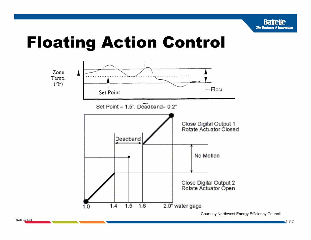
Floating Action ControlFloating Action Control
1-57PNWD-SA-8834
Courtesy Northwest Energy Efficiency Council

P ti l C t l A tiProportional Control Action
Proportional Control Action
1-58PNWD-SA-8834
Courtesy Northwest Energy Efficiency Council

Proportional with I t l C t l (PI)Integral Control (PI)
Proportional Plus Integral (PI) Control Action
1-59PNWD-SA-8834
Courtesy Northwest Energy Efficiency Council
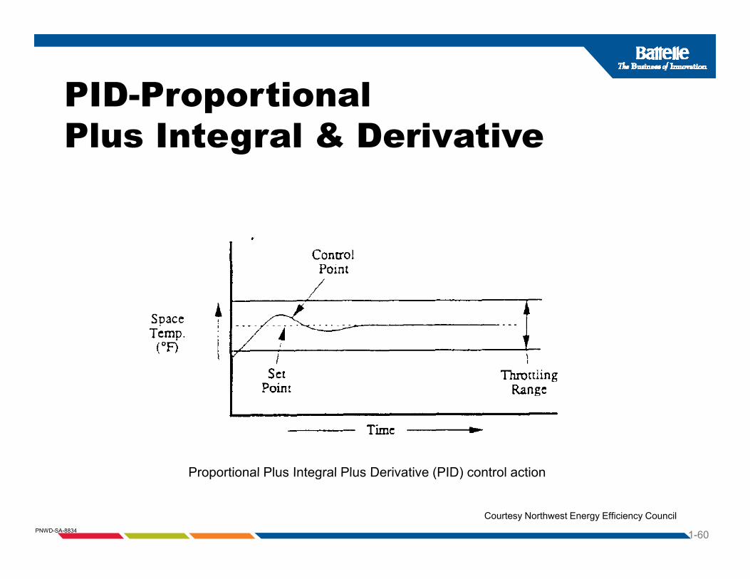
PID-Proportional pPlus Integral & Derivative
Proportional Plus Integral Plus Derivative (PID) control action
1-60PNWD-SA-8834
Proportional Plus Integral Plus Derivative (PID) control action
Courtesy Northwest Energy Efficiency Council

Adaptive ControlAdaptive loop tuning provides:•Accurate, continuous loop control•Faster tuning of loops for energy savings •Less wear on valves, actuators, fans, pumps, dampers, VFDs, etc.VFDs, etc.
1-61PNWD-SA-8834
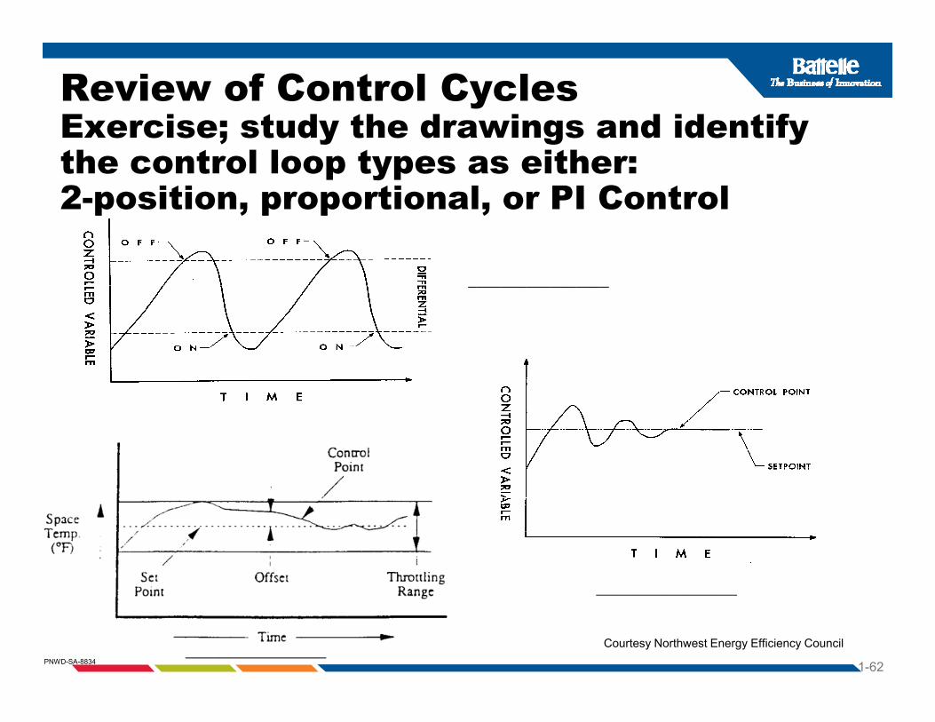
Review of Control CyclesExercise; study the drawings and identify Exercise; study the drawings and identify the control loop types as either:2-position, proportional, or PI Control
_________________
1-62PNWD-SA-8834
_________________
_________________ Courtesy Northwest Energy Efficiency Council
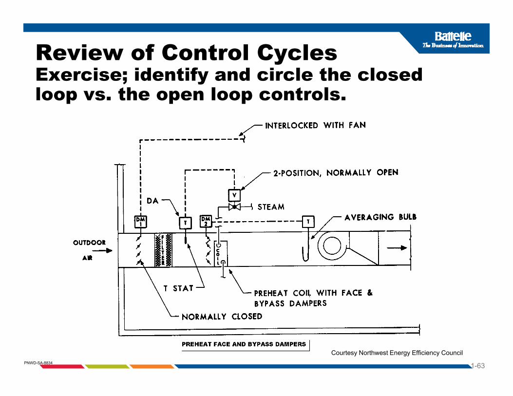
Review of Control CyclesExercise; identify and circle the closed Exercise; identify and circle the closed loop vs. the open loop controls.
1-63PNWD-SA-8834
Courtesy Northwest Energy Efficiency Council

Review of Control CyclesyExercise; review the drawing and identify setpoint, control point, TR, and offsetand offset.
1-64PNWD-SA-8834
Courtesy TAC Controls/Schneider Electric
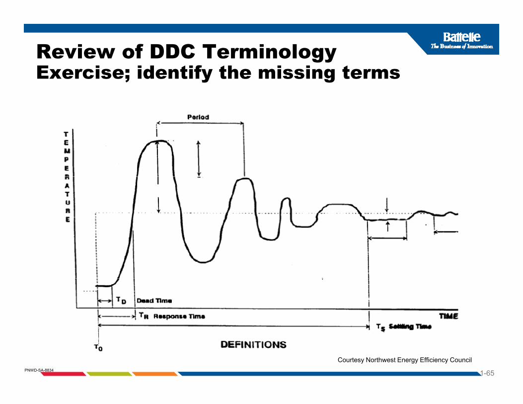
Review of DDC TerminologyExercise; identify the missing termsExercise; identify the missing terms
1-65PNWD-SA-8834
Courtesy Northwest Energy Efficiency Council

Section 7Control Energy SourcesControl Energy SourcesA power supply or source of energy is needed to
power the control system Control systems usepower the control system. Control systems use either a pneumatic or electric power supply.
• Pneumatic controls use a compressed gas as aPneumatic controls use a compressed gas as a source of energy, typically compressed air.
• Electric and electronic controls could beElectric and electronic controls could be powered by a variety of electrical power supplies of either alternating current (AC) or direct current (DC)(DC).
• DDC-Direct digital controls are considered electronically powered via a network of controls
1-66PNWD-SA-8834
electronically powered via a network of controls.

Comparing Advantages And DisadvantagesAnd Disadvantagesof pneumatics and DDC controls
•Pneumatic control systems•Low maintenance, ease of testing•Hard to integrate into DDC systems•Requires air compressor station
DDC Di t di it l t l•DDC – Direct digital control •High accuracy•Flexible easy to access•Flexible, easy to access•Programmable
•Energy management considerations
1-67PNWD-SA-8834
•Energy management considerations•Easy to optimize, reduce kW peaks, schedule
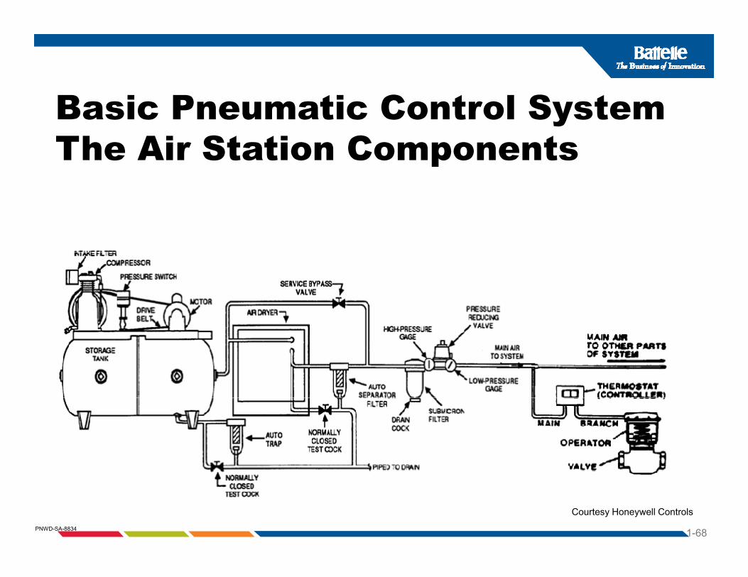
Basic Pneumatic Control SystemBasic Pneumatic Control SystemThe Air Station Components
1-68PNWD-SA-8834
Courtesy Honeywell Controls

Basic Pneumatic Control SystemBasic Pneumatic Control System
1-69PNWD-SA-8834
Conventional Pneumatic Control Systems
Requirements:
Clean and dry air supply Clean and dry air supply
Pressure reducing valve Pressure reducing valve
Utilizes pneumatic controllers
Pneumatic devices
1-70PNWD-SA-8834
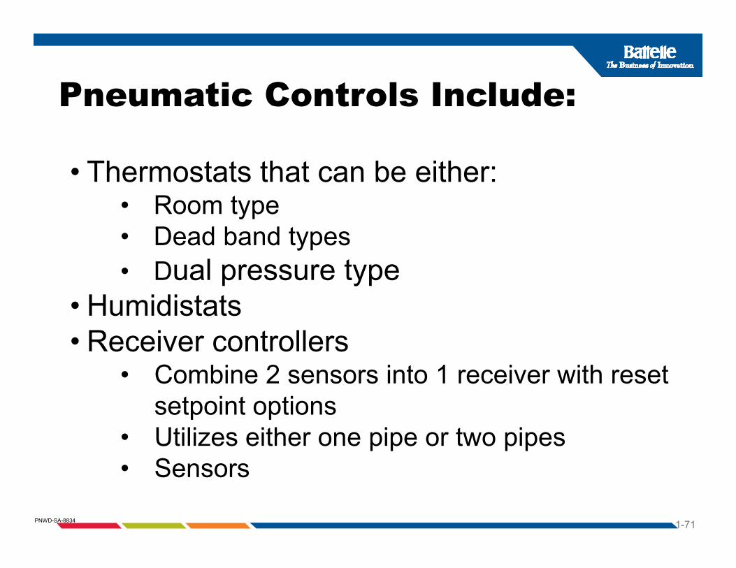
Pneumatic Controls Include:
• Thermostats that can be either:
Pneumatic Controls Include:
Thermostats that can be either:• Room type• Dead band typesyp• Dual pressure type
• Humidistats• Receiver controllers
• Combine 2 sensors into 1 receiver with reset setpoint options
• Utilizes either one pipe or two pipes Sensors
1-71PNWD-SA-8834
• Sensors

Pneumatic Control of Heating Coil Control with Reset
1-72PNWD-SA-8834
Courtesy Northwest Energy Efficiency Council

Pneumatic Control System AccessoriesAccessories
Pneumatic relays: Reversing relay Reversing relay High/low pressure selector Air motion Signal repeating
Pneumatic Switch
Signal repeating Minimum position
EP-Electric to Pressure Switch
1-73PNWD-SA-8834
EPs and PEs PE-Pressure to Electric Switch

B i P ti C t l S tBasic Pneumatic Control System
1-74PNWD-SA-8834

Example of Pneumatic ControlsExample of Pneumatic Controls
1-75PNWD-SA-8834
Courtesy LAMA Books

Basic Electric Control
1-76PNWD-SA-8834
Courtesy Honeywell Controls

Example of Electric Controls a p e o ect c Co t o sfor Economizers
1-77PNWD-SA-8834
Courtesy Honeywell Controls

Simple Electronic Control S tSystem
1-78PNWD-SA-8834
Courtesy Honeywell Controls

Example of Electronic Control for Example of Electronic Control for Basic AHU Economizer Control
1-79PNWD-SA-8834
Courtesy Honeywell Controls

Example of Electronic Control for Economizers with Differential Enthalpy Economizers with Differential Enthalpy and CO2 Demand Ventilation Control
1-80PNWD-SA-8834
Courtesy Honeywell Controls
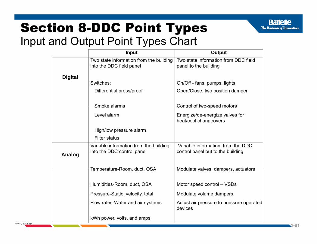
Section 8-DDC Point TypesInput and Output Point Types Chartp p yp
Input Output
Di it l
Two state information from the building into the DDC field panel
Two state information from DDC field panel to the building
DigitalSwitches: On/Off - fans, pumps, lights
Differential press/proof Open/Close, two position damper
Smoke alarms Control of two-speed motorsSmoke alarms Control of two speed motors
Level alarm Energize/de-energize valves for heat/cool changeovers
High/low pressure alarmFilter statusFilter status
AnalogVariable information from the building into the DDC control panel
Variable information from the DDC control panel out to the building
Temperature Room duct OSA Modulate valves dampers actuatorsTemperature-Room, duct, OSA Modulate valves, dampers, actuators
Humidities-Room, duct, OSA Motor speed control – VSDs
Pressure-Static, velocity, total Modulate volume dampers
1-81PNWD-SA-8834
Flow rates-Water and air systems Adjust air pressure to pressure operated devices
kWh power, volts, and amps
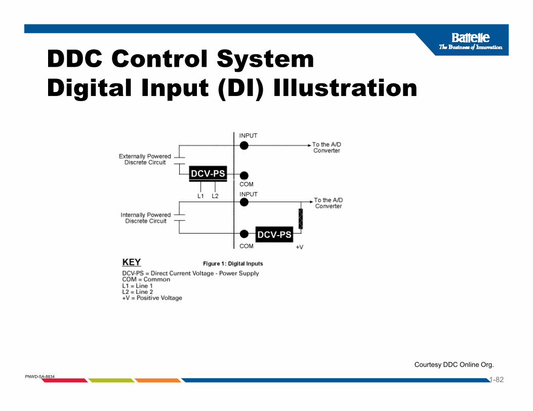
DDC Control System Digital Input (DI) Illustration
1-82PNWD-SA-8834
Courtesy DDC Online Org.

DDC Control System Digital Input (DI) IllustrationFlow Switch
1-83PNWD-SA-8834
Courtesy Honeywell Controls

DDC Control System Digital Input (DI) Pulsed SignalIllustrationFlow Switch
1-84PNWD-SA-8834
Courtesy Verris Industries
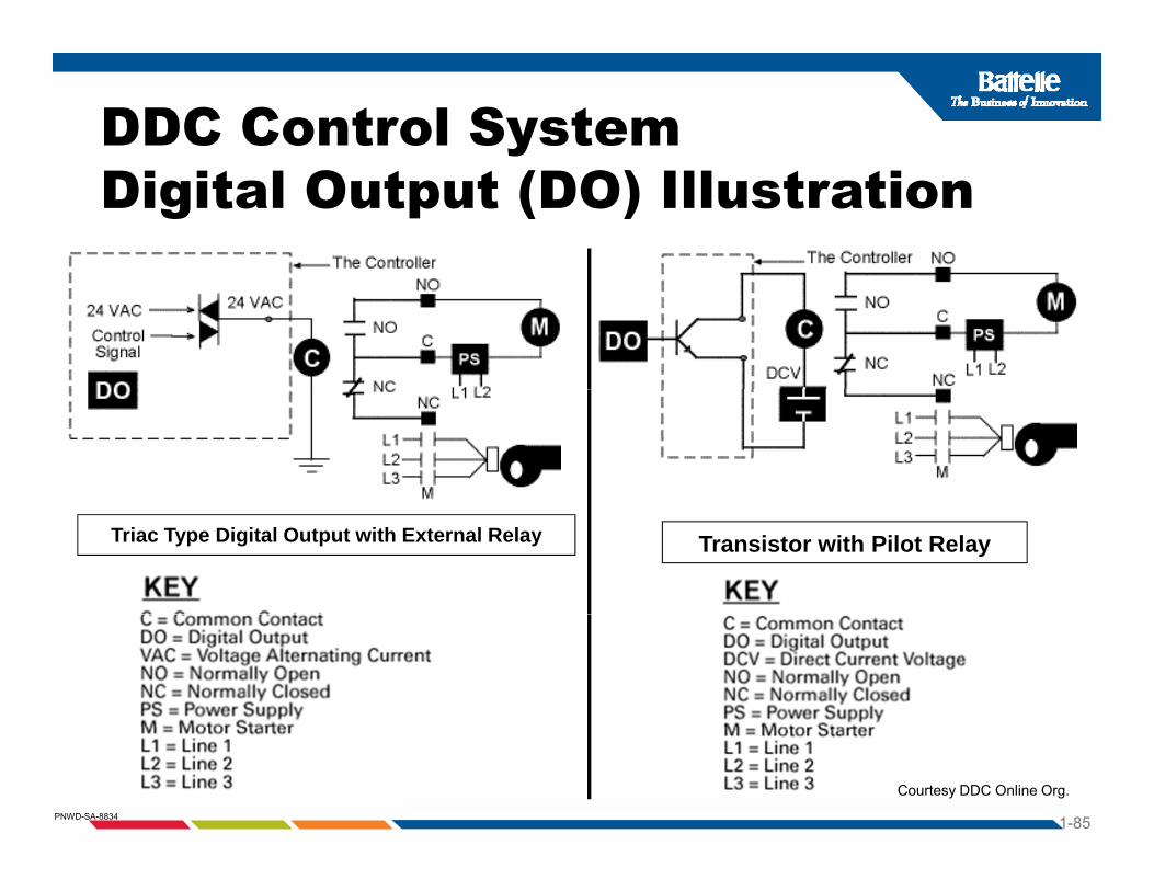
DDC Control System Digital Output (DO) Illustration
Transistor with Pilot RelayTriac Type Digital Output with External Relay
1-85PNWD-SA-8834
Courtesy DDC Online Org.

DDC Control System A l I t (AI) Ill t tiAnalog Input (AI) Illustration
1-86PNWD-SA-8834
Courtesy DDC Online Org.

DDC Control System Analog Input (AI) IllustrationFor Measuring Air Flow in FPMg
1-87PNWD-SA-8834
Courtesy Dwyer Instruments.

DDC Control System Analog Output (AO) IllustrationFor controlling a pneumatic valveg p
1-88PNWD-SA-8834
Courtesy TAC Controls/Schneider Electric
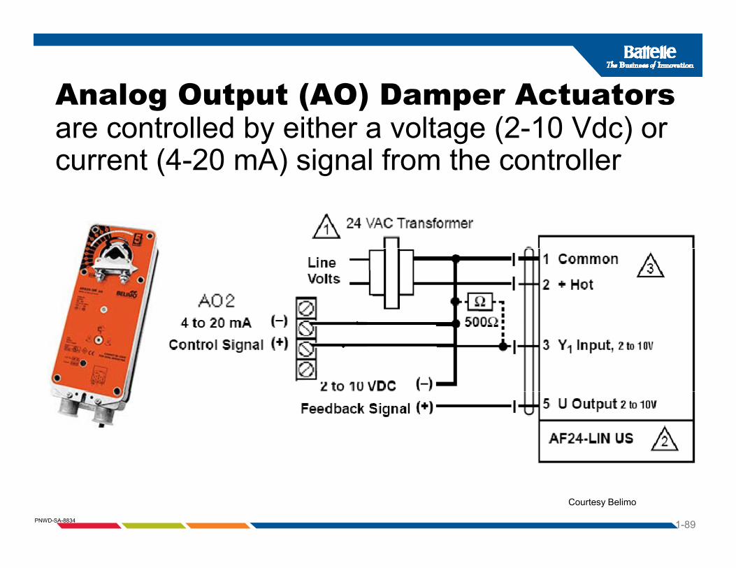
Analog Output (AO) Damper Actuators g p ( ) pare controlled by either a voltage (2-10 Vdc) or current (4-20 mA) signal from the controller
1-89PNWD-SA-8834
Courtesy Belimo

Example of DDC AHU Control pApplication with Point Types Identified
1-90PNWD-SA-8834
Courtesy Honeywell Controls.

ExerciseReview of DDC TerminologyReview of DDC Terminology
1-91PNWD-SA-8834
Courtesy TAC Controls/Schneider Electric

ExerciseReview of DDC TerminologyReview of DDC Terminology
1-92PNWD-SA-8834
Courtesy TAC Controls/Schneider Electric