Embed Size (px)
DESCRIPTION
Edited by RMAF Fire School based on new curriculum for Fire Technician Course students
Citation preview

238
FT 42 AUTOMATIC ALARM SYS
AUTOMATIC FIRE DETECTORS (Beam Master) OBJECTIVE
1. To explain the automatic fire detector beam master that is a combination of heat and smoke detection and their function and operation. REFERENCE
2. a. Manual of Fireman ship Book 9. b. Fire College Notes. CONTENTS 3. Introduction. The beam master generally purpose fire detector capable of
responding to heat and smoke. It may be used to protect virtually all indoor risks and a single emitter and receiver unit coves up to 12,000 sq, ft (115 m2) thus replacing up to 12 conventional point type detectors. 4. The beam master makes use of a continuously monitored beam of infra-red light, which may be as long as 328 ft. (100.0m) and it automatically raises a fire alarm if it detects smoke or thermal turbulence caused by heat anywhere along the line between the emitter and the receiver. 5. Many areas can only be protected with difficulty with point type detectors but lend themselves to the use of the beam principle. Some examples of these are listed below:
a. Large and high buildings such as aircraft hangers.
b. Historic building where a minimum of interference with the decorations and the fabric of the building is important.
c. Production areas where other types of detectors may be difficult to install and maintain a where too many of them would be required.
d. Were houses, in which the contents may change, requiring either a smoke or heat detector?
6. The Beam Master System. The basic beam master system consists of an emitter
unit and a receiver unit. A pulsed beam of infra-red light passes between the emitter and receiver and is affected in different ways by the smoke and the thermal turbulence caused by a fire. When these changes are detected by the receiver the FIRE relay latches and the appropriate smoke or heat internal indicating lamps are lit. External electrical signals are sent to the remote indicator and control unit. If the beam is completely obscured, as by the jib of a passing crane, the receiver FAULT relay de-energize; the internal fault indicating lamp is lit; and the system healthy indicating lamp goes out. External electrical signals are sent to the remote indicator and control unit. On removal of the obstruction all system functions return to normal.

239
7. Equipment Description
a. Construction. The emitter and receiver of the beam master system are
housed in die-cast aluminum weatherproof casings or in similar fabricated sheet steel boxes, as shown in Figure 1.
Fig.1. Beam Master Emitter and Receiver Units
(1) The front of each of the complete with its acrylic window is easily removed, by unscrewing the four cover screws located at the corners. This gives access to the connector block, the optical system and the electronics.
(2) The front of each unit is attached to the casing by plastic straps so that it cannot be dropped.
(3) Gland plates are fitted to the top and bottom of each unit for cable entry.
b. The Emitter. The emitter contains an optical system, the light source and the
circuitry which controls the source. The important components of the emitter are annotated in Figure 2.
(1) The Beam. The beam is produced by a gallium arsenide light emitting
diodes, known as the LED, located at the focal point of a molded plastic lens. The beam is not highly collimated since this would lead to difficulty in maintaining alignment between the emitter and receiver. Instead the spread of the beam employed is approximately 1 meter diameter over a path length of 100 meters.
(2) The LED emits a sharp peak of radiation in the infra-red part of the spectrum centered around 940 nanometers.
(3) The beam is off for 95.5% of the time since it is pulsed for 5 microseconds once every millisecond. A more intense beam can be produced during the pulses than would otherwise be the case, so increasing the sensitivity of the system.

240
Figure 2. Layout of the Emitter
c. The Receiver. The receiver detects change in the beam caused by
conditions along its path. A part of the beam enters a similar optical system to that of the emitter and is focused onto a light sensitive transistor known as the photo-transistor. The resulting pulses are then amplified and processed to detect a smoke, heat (turbulence) for fault condition. Smoke or heat detection latches the FIRE relay, whereas fault detection causes de-energization of the FAULT relay for the duration of the fault.
d. The important components of the receiver are annotated in Figure 3.

241
Figure 3. Layout of the Receiver
e. The optical assembly is rigidly mounted on the back of the casing. Also mounted on the back is a printed circuit board which supports the electrical component of the unit and connects them to each other (motherboard). These components are two further printed circuit boards, the relays, the connectors TS3 for the phototransistor and the connector block for the system wiring.
f. As an option filament lamps are replaced by LED’s and are angled downwards. The order of the lamps is then from top to bottom:
(1) Heat (2) System Healthy (3) Fault (4) Smoke
8. Remote Indicator and Reset Switch. The remote indicator and reset switch is a
compact – unit which allows indications of the Beam Master to be displayed in a prominent position. 9. The indicators, which are light emitting diodes, are for FIR (SMOKE and/or HEAT indicated by the receiver) FAULT, and POWER ON. 10. The reset switch is key operated and interrupts the power supply to the receiver.

242
11. Principles of Operation Summary. A pulsed beam of infra-red light traverses the protected area just below the ceiling. At the receiver end of the beam it is focused onto a phototransistor the output from which is amplified and passed to the fault, smoke and heat channels for analysis. See Figure 5.
Figure 5. Beam Master Detection Principles
12. The Emitter. Emitter functional description. Many of the principles of operation of the Beam Master are realized by the use of a gallium arsenide light emitting diode, the FED, as the source. These are as follows:
a. The photo-transistor, which is the light sensor in the receiver, is sensitive to a wide spectrum in the infra-red, with a diminished response curve. This combination of source and sensor therefore forms the basic of a system which is sensitive to changes in intensity of the beam but relatively insensitive to change in ambient lighting conditions.
b. The LED emits light a small area. By placing such a source in the focal plane of a lens a slightly divergent beam is formed which bathes the lens in the beam but relatively insensitive of the system to errors of drift in beam alignment and vibration.
c. Because the beam may be as long as 100 meters accuracy is still required in beam alignment. The lens and LED are therefore mounted in an assembly which can be rocked on a spherical seating by two adjusting screws working at right angels against a return spring. This system enables the direction of the beam to beam to be adjusted without moving the LED away the focus of the lens.
d. The emission beam angle of the LED between half power points is 35. The aperture of the lens is therefore large enough for a high proportion of the light to be gathered into the beam.
e. The reduction in efficiency during the life of an LED is low compared with other sources, giving a beam with a low drift in intensity. LED’s are highly reliable.
f. LED’s are easily controlled by transistors and have short turn on and turn off times. By switching on the LED for 5 micro-seconds once every millisecond, pulses of far higher intensity can be produced than would be possible for a continuous beam. The receiver reacts to the peak intensity.
g. The light output is primarily dependent on the LED current. This current is supplied by a constant current transistor stage in the emitter output circuit. Slow changes in temperature of the LED casing, are compensated for by the receiver.

243
13. The circuitry of the emitter consists of voltage stabilization components and a square wave generator/monostable/transistor switch combination controlling the FED. Emitter: circuit description. See Circuit Diagram CD 1. 14. Power is applied via fuse FSI to protect against over current, and diode MR2, which protects against reversed polarity of the supply. 15. A 5.6 V d..c. supply for ICI and VTI is provided by R4 and zenerdiode MR1. This voltage can be measured at TP1. 16. ICI is a quad two input NAND integrated circuit, connected as a square wave generator. The nominal frequency of 1 kHz is controlled by the R3, C3 time constant. The square can be monitored at TP2. 17. Transistor VT1 is coupled to the output of the square ware generator by differentiating network R1, C1. This arrangement causes VT1 to be turned off for a nominal 5 microsecond period following each negative-going edge of the square wave. The VT1 collector waveform consists of 5 micro-second positive pulses with a pulse repetition frequency of 1 kHz and a height of about 5V. 18. R6 enables current pulses in the LED to be monitored at TP3 and limits the LED current during pulses. 19. The Smoke Channel. In the smoke channel the beam intensity is compared with its intensity about ten minutes previous to allow the channel to ignore slowly changing conditions, such as drift in component valves, or drift in beam alignment. A level, usually 50%, is set by resistor selection such that if the intensity falls below this valve the presence of smoke is deemed to have been detected. A subsequent delay of up to 6 seconds is included to prevent an alarm from being caused by transient conditions, following which the fire relay is latched by a thyristor to raise the alarm. 20. The Heat Channel. Any fire producing appreciable quantities of heat causes thermal
turbulence, and it is this which is detected by the Beam Master. In such conditions the light is deflected by refraction as it passes through air of varying temperature and composition, causing fluctuations in the intensity detected by the receiver. The fluctuations may be above or below the undisturbed level because the light may be deflected towards as well as away from the receiver lens. The frequency of fluctuation is dependent upon the size of the fire and ranges from about 1 Hz for a large fire to about 30 Hz for a small one. Fluctuations due to heaters tend to be outside this frequency band, being typically higher for fan heaters and lower for radiators. 21. In his heat channel, therefore, fluctuations, within a band of frequencies corresponding to shimmering of the beam, latch the fire relay by thyristor action if they exceed pre-set amplitude. An electrical deal is provided before the thyristor action, which avoids false alarms caused by the transient ambient conditions. Receiver: Circuit Description See CD2 and CD3 Circuit Diagram Stabilized power supplies. 22. Power supplied to the receiver via SW1 which is also the local RESET switch; fuse FS1 which provides over current protection; and diode MR1 which protection against reverse polarity of the supply voltage. 23. A 20 V reference voltage produced by resistor R1, sneer diode MR2 and smoothing capacitor C34 is applied to the base of transistor VT1. Resistors R3 and R4 are a voltage divider providing a 10V bias supply which is decupled by capacitor C1.

244
24. The Receiver. Receiver: Functional Description. The photo-transistor, optical assembly, pre-amplifier and peak detector. 25. The early of the receiver are concerned with the generation of a voltage which is analogous to the intensity of the beam when it reaches the receiver. 26. The sensor is a silicon photo-transistor with a suitable spectral response, see Emitter Functional Description. The photo-transistor is located in the focal plane of the focal plane of a lens in an optical assembly similar to that of the emitter, but the function of the assembly is to focus the beam onto the sensitive region of the photo-transistor. The lens has two effects. The lens has two effects. Firstly, sensitivity to the beam is increased and secondly, sources of light situated away from the axis of the beam are imaged outside the sensitive region of the photo-transistor so that for these the lens acts as a mask. 27. An LED (flooding diode) is provided to ensure a suitable level of illumination on the photo-transistor at all times. 28. The output from the photo-transistor, consisting of noise, a d.c. component and pulses, is fed to a volume control and thence via a small capacitance to the pre-amplifier. The capacitate coupling block the d.c. component and the band width of the amplifier is limited to enhance the pulses relative to the noise level. 29. The amplified pulse is passed to a peak detector which has a delay time constant of about 1 milliseconds. This type of detector provides a d.c. output voltage which is proportional to the peak voltage of the incoming pulses. The millisecond delay bridges the gap between successive pulses while still permitting the detector to follow relatively fast changes in the intensity of the received light. 30. The Fault Channel. In the fault channel a comparison is mad between the beam
intensity and a level which is pre-set to about 20% of normal. A reduction in intensity below this level is deemed to be due to a system failure of the power supply, the emitter or the pre-amplifier. The smoke channel, see Receiver Functional Description is immediately disabled to prevent a false fire alarm, and after a delay of up to 1.5 seconds the fault relay is de-energized to signal the FAULT condition. The delay is included so that faults of a nature may be ignored. In earlier models the fault relay was energized for about one second to give the signal. 31. Photo-Transistor and Pre-Amplifier. Transistor VT13, 14 and 3 and associated
components are a direct coupled pre-amplifier with an open loop gain of about 10,000. Two negative feedback paths are incorporated. Resistors R54 and R57 provide a d.c. feedback path which sets the d.c. level at the output. This feedback path is decoupled by C30 above 3 Hz. The a.c gain feedback path which consists of R56, C32, C29, R55 and R6, defines the gain in the mid-frequency band. Capacitors C28 and C31 provide high frequency and low frequency roll-off, respectively. The a.c. gain with feedback is approximately 1000. With the inclusion of C27 the band width of the pre-amplifier is 7 to 500 kHz. The response at mains frequency is about 40 dB -down. Extension of the frequency response frequency is not necessary because the turn-on time of the photo-transistor is 3 microseconds. 32. The photo-transistor is powered from the 20 V supply line and potentiometer VR1 acts both as the emitter load and gain control. Due to background illumination and light from the flooding diode a standing voltage exists on the slider of VR1, which is blocked by capacitor C27. 33. Pulse Height Detector. Transistor VT4 and associated components from a pulse
height detector referenced to the 10 V supply line. Positive pulses from the pre-amplifier capacitor C3 via diode MR5 tending to turn the transistor on the increase the output voltage on the emitter.

245
34. Resistor R71 and R72 bias the base of VT4 to make the transistor responsive to pulses of low height. The R9, C3 time constant of 0.8ms is chosen to sustain the output voltage between pulses while still allowing a rapid response to a reduction in pulse height. 35. Test Point TP5, Calibration Voltage. Components C4, MR6 and C5 provide a voltage which corresponds to beam intensity referenced to the O V line suitable for measurement with a high impedance d.c. voltmeter. 36. Smoke Channel. Smoke channel consists of integrated circuit IC2, transistor VT5,
thyristor SCR1 and associated components. 37. The output from the pulse height detector is smoothed by components MR7, R11 and C6 to provide a signal analogous to the measured beam intensity over the previous 5 ms. This signal may be measured at TP4, since the zero level for the signal is 10 V. See also Stabilized Power Supplies. Integrated circuit IC2 is an operational amplifier used as a voltage comparator. The inverting input, pin 2, receives the mean intensity signal. For the non-inverting input, pin 3, a signal is generated which represents a fraction of the intensity of the beam about 10 minutes previous. The attenuation of the R12, R13 combination sets the threshold for beam obstruction, and the delay is produced by the R14, C7 time constant. Diode MR9 is required to prevent discharge of C7 via R12 and R13 during periods of obstruction, and MR8 compensates for the presence of MR9. 38. If obscuration of the beam by more than the set amount occurs within the delay period, IC2, pin 2 becomes negative with respect to pin 3 and the output, pin 6, goes high to trigger thyristor, SCRI. The attenuation provided by R16 and R17 prevents an excessively high voltage from being applied to the gate electrodes of the thyristor and the R17, C9 time constant delays triggering by 6 seconds minimum to avoid false alarms. 39. A rapid reduction of the beam to 20% of its intensity represents a fault. In these circumstances the FAULT LINE signal, attenuated by R19 and R18 to avoid excessive base voltage, turns on VT5. The gats electrode of SCR1 is thus clamped to O V to inhibit the SMOKE signal. 40. Heat Channel. The heat channel consists of IC4, VT11, VT6, VT7, SCR2 and
associated components. 41. Integrated circuit IC4, R23 to 29 and C15 to 20 from an amplifier with an overall gain of about 100 within the frequency band 1 to 30 Hz. The input signal to the amplifier is the output of the peak detector which faithfully follows fluctuations in the beam intensity. Fluctuations within the 1 to 30 Hz band are those most likely to be caused by a fire, and it is the amplified version of these which appear at the output of the amplifier. 42. Field effect transistor VT11, R30, 31, 32, C22 and MR10 and 11 from a men amplitude detector, coupled to the amplifier by C21. When the amplifier output voltage exceeds the voltage on C22 the capacitor is changed through MR11 and R31; otherwise the charge drains through R32 and R30. Since the voltage on the source electrode of VT11 follows that on the gate electrode, the voltage across potentiometer VR2, HEAT THRESHOLD, is analogous to the amplitude the O V rail during negative to the mean positive half cycle level. This voltage can be measured at TP2. Note, however that at this teat point the voltage measured includes the 2.3 V bias required by the F.E.T. 43. Transistor VT6 is connected as a voltage comparator. As the base voltage increases above the sneer voltage for MR12 the transistor is turned on and the collector voltage falls. The level of beam fluctuations at which this occurs depends upon the setting of VT2.

246
44. When comparator VT6 is turned on the voltage at TP3 drops and current flows in VT7 developing sufficient voltage across R40 to trigger SCR2, without exceeding the maximum gate electrode voltage. The HEAT LINE signal is latched by firing SCR2. The triggering action is slugged, however, by capacitor C24 to prevent false alarms due to transient conditions. Thus the signal is latched when the heat threshold has been exceeded continuously for a period determined for a period determined by R39, R40 and C24, C25 prevent SCR2 from firing in response to any fast rate of change of voltage on its anode, due to transients on the supply line. When the thyristor fires, the voltage on the gate electrode increases from about 0.5 to 0.9 volts. Diode MR13 prevents charging of C24 from the electrode to facilitate resetting. 45. Fault Channel. The fault channel consists of ICI, VT 12 and associated component. 46. Integrated circuit ICI is used as a voltage comparator. A comparison voltage appears at the slider of potentiometer VR4, SET FAULT THRESHOLD, which is part of the voltage divider chain R21, VR4, R61. The threshold voltage, which can be measured at TP9, is smoothed by C34. If the mean beam intensity signal applied to ICI, pin 2 becomes negative with respect to the comparison voltage on pin 3, the output on pin 6 goes high. 47. This immediately inhibits SMOKE SIGNAL, SEE Receiver Functional Description Smoke Channel. 48. Transistor VT12, R64, 65, 67, 68 and C14 invert the FAULT LINE signal. R64 and R65 attenuate to prevent signal excessive base voltage on V12. Capacitor C14 delays the inverted signal by about 1 second to prevent false alarms due to transient conditions. 49. The purpose of MR3 and C33 is explained in Receiver Functional. 50. Indicating Lamps. Indicators are normally 28 V incandescent lamp, but in the version of the Beam Master that is used at high levels LEDs are employed with series resistors in a similar circuit. 51. If smoke is detected, the SMOKE SIGNAL line has a low impedance to the O V rail, and LP1 is turned on. Current also from the 24 V rail through relay RLB and MR18 to energize the FIRE relay. Diode MR17 suppresses inductive transients produced by the relay coil. If the HEAT LINE signal goes negative, by similar action, LP4 is turned on the FIRE relay is again energized, in this case via MR19. 52. If a fault is detected FAULT LINE goes positive immediately turning on VT9 and lighting LP2. A short time later the SYSTEM NORMAL line goes low. This switches off LP3 via VT8 and also switches off VT10 to de-energize the FAULT relay, RLA, which is in parallel with MR15. For the purpose of MR16 and C25, see Description – Pulsed Fault Relay Operation. 53. Pulsed Fault Relay Operation Prior To Serial Number 553. To operate the fault
relay for a short time after the detection of a fault, IC2, pin 6 was capacitatively coupled to the base of VT10. To enable the pulse to occur in the event of power supply failure the fault channel was supplied through MR3 and MR16 with C33 and C23 as reservoir capacitors. These components are retained for case of reversion to the pulsed fault relay mode of operation. 54. Conditions on Initial Application Of Power. Resetting of the Beam Master is by
interruption of the power supply. C34 is initially discharge so pin 3 of ICI is at the negative rail. Pin 2 will be at 10 V sp ICI is initially biased to give a SYSTEM NORMAL indication for approximately 3.5 seconds following switch on. When C34 has charged to its normal voltage via R21 and VR4 the correct comparator action is established.
247
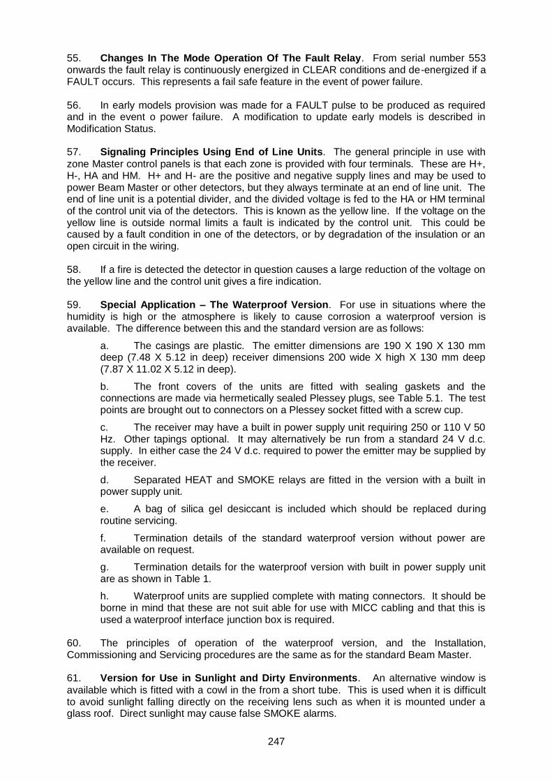
55. Changes In The Mode Operation Of The Fault Relay. From serial number 553 onwards the fault relay is continuously energized in CLEAR conditions and de-energized if a FAULT occurs. This represents a fail safe feature in the event of power failure. 56. In early models provision was made for a FAULT pulse to be produced as required and in the event o power failure. A modification to update early models is described in Modification Status. 57. Signaling Principles Using End of Line Units. The general principle in use with
zone Master control panels is that each zone is provided with four terminals. These are H+, H-, HA and HM. H+ and H- are the positive and negative supply lines and may be used to power Beam Master or other detectors, but they always terminate at an end of line unit. The end of line unit is a potential divider, and the divided voltage is fed to the HA or HM terminal of the control unit via of the detectors. This is known as the yellow line. If the voltage on the yellow line is outside normal limits a fault is indicated by the control unit. This could be caused by a fault condition in one of the detectors, or by degradation of the insulation or an open circuit in the wiring. 58. If a fire is detected the detector in question causes a large reduction of the voltage on the yellow line and the control unit gives a fire indication. 59. Special Application – The Waterproof Version. For use in situations where the humidity is high or the atmosphere is likely to cause corrosion a waterproof version is available. The difference between this and the standard version are as follows:
a. The casings are plastic. The emitter dimensions are 190 X 190 X 130 mm deep (7.48 X 5.12 in deep) receiver dimensions 200 wide X high X 130 mm deep (7.87 X 11.02 X 5.12 in deep).
b. The front covers of the units are fitted with sealing gaskets and the connections are made via hermetically sealed Plessey plugs, see Table 5.1. The test points are brought out to connectors on a Plessey socket fitted with a screw cup.
c. The receiver may have a built in power supply unit requiring 250 or 110 V 50 Hz. Other tapings optional. It may alternatively be run from a standard 24 V d.c. supply. In either case the 24 V d.c. required to power the emitter may be supplied by the receiver.
d. Separated HEAT and SMOKE relays are fitted in the version with a built in power supply unit.
e. A bag of silica gel desiccant is included which should be replaced during routine servicing.
f. Termination details of the standard waterproof version without power are available on request.
g. Termination details for the waterproof version with built in power supply unit are as shown in Table 1.
h. Waterproof units are supplied complete with mating connectors. It should be borne in mind that these are not suit able for use with MICC cabling and that this is used a waterproof interface junction box is required.
60. The principles of operation of the waterproof version, and the Installation, Commissioning and Servicing procedures are the same as for the standard Beam Master. 61. Version for Use in Sunlight and Dirty Environments. An alternative window is
available which is fitted with a cowl in the from a short tube. This is used when it is difficult to avoid sunlight falling directly on the receiving lens such as when it is mounted under a glass roof. Direct sunlight may cause false SMOKE alarms.

248
62. In dirty environments to excessive attenuation of the light beam due to contaminated windows, should windows are fitted to both emitter and receiver units. 63. The Screened Version. In conditions of high ambient levels to electro-magnetic
radiation, screens are fitted inside the covers of the emitter and receiver units. Such conditions occur near radar, navigation aid or communications equipment. A system fitted with this modification has been shown to operate reliability at London Airport Radar Station where, in addition acoustic vibration due to heavy aircraft was experienced. In such installation it is essential that both units are earthed. 64. The screen is made of expanded and flattened aluminum mesh and used the shroud retaining screws as fixings. Fitting details are given in figure 6. Earthling of the screen is via the fixing screws. 65. Version for Use at High levels. For use at high levels or in otherwise relatively inaccessible positions the high level version of the Beam Master is an available. 66. In this version the incandescent lamps are replaces by light emitting diodes and series resistor. The light emitting diodes are angled downwards to increase visibility and their enhanced reliability obviates lamp failure between service visits.
Figure 6 R.F Screen
67. Ventilation Control Version. A version exists which detects preset levels of haze
produced by exhaust fumes, steam, welding oxyacetylene cutting or other industrial process. 68. Ventilation system may be controlled automatically to minimized potential excess heat losses. Operating details are available on request.
Connector Number Function
a. 3 way Plessey plug (main), receiver Plug A.
A 110 or 250V a.c B 110 or 250V a.c C earth

249
b. 6 way Plessey socket (test points) receiver socket B.
A TP2 B TP3 C TP5 D TP6 E TP7 F not connected
c. 6 way Plessey plug (alarm contacts), receiver Plug B
A FAULT relay, changeover contact.
B. FAULT relay, normally open contact (connected) to a when CLEAR).
C. HEAT relay, changeover contact.
D HEAT real, normally closed contact (C disconnected from D signal HEAT).
E. SMOKE relay, changeover contact.
F. SMOKE relay, normally closed contact (E disconnected from F signal SMOKE).
d. 3 WAY Plessey socket (emitter supply), receiver socket
A 24 V d.c. positive. B 24 V d.c. negative. C -
e. 3 way Plessey plug (emitter supply), emitter plug A.
A 24 V d.c. positive. B 24 V d.c. negative. C -
Table 1. Receiver and Emitter Connections (Waterproof Version with Power Supply)
69. Installation - Location. The emitter and receiver units of the Beam Mater system
have to face other at either end of the planned beam position. Careful measurement of the height and width of the building should be made to ensure that the beam is as nearly as possible aligned mechanically prior to commissioning. 70. Careful sitting of the beam is important to the efficient operation of the system. The beam axis should be between 0.12 and 1.9 m (4.73 and 36.3 in). From a flat ceiling or apex, but as high as possible within this range. Refer to figure 7 which shows typical positioning of the beams. 71. Note that when considering an apex roof it is normally adequate to have beam near the apex if the span is less than 28 m (92 ft). For spans between 28 m (92 ft) and 84 m (276 ft) there beams are necessary, one near the apex and two positioned as shown in figure 7. 72. Although the emitter and receiver may be installed in any orientation or in recesses, without affecting the performance the labels must be in positions where they are subsequently visible and able to be read. The wide flanges on the units should preferably be uppermost since they retard contamination of the windows.

250
73. Special considerations have to be taken into account where there is a risk of stratification of the smoke, due possibly of the generation of cold smoke. In such cases the beam should be installed at the level where the stratification is anticipated and it should be appreciated that the heat detection facility is lost. At least one detector at ceiling level should be retained. 74. To be able to set a suitable threshold level for HEAT alarm the beam should not traverse regions where a high degree of turbulence normally exists. Such places are:
a. Close to holes or ventilators in the roof or eaves of a centrally heated building. b. Close to a steam pipe heater. c. Within 1 m (3.3 ft) of a blower heater.
75. In addition for the receiver to respond to the infra-red beam it should not be exposed to bright shining directly into the lends, nor be mounted within 1.5 m (4.9 ft) of a light fitting. 76. From the access and servicing points of view the units should preferably be installed at the ends of a building, at points where a ladder may be learned against the wall.
Note:
FOR WINDER BUILDING USE A SIMILAR SEQUENCE BUT THE DISTANCE BETWEEN THE FIRST BEAM AND THE ADJACENT WALL MUST BE LESS THAN 8 M (26.2) AND THE DISTANCE BETWEEN BEAMS MUST BE LESS THAN 16 M (52.5)
Figure 7

251
77. Mounting. The emitter and receiver units may be mounted in any orientation. This allows them, if necessary, to be mounted in recesses running horizontally or at an angle. In addition the however, that the wide flanges, which is normally at the top and retards contamination of the windows, they serves no purpose. 78. Since the beam has to be carefully aligned, both units must be securely fixed to rigid building members. Screws and plugs are supplied with each unit for this purpose. Fixing to any wooden or other member liable to warp is not satisfactory. Avoid mounting on light weight cladding such as sheet steel, asbestos sheet or corrugated aluminum. In these circumstances a request should be made for a stanchion to be provided. 79. Templates are provided for the positions of the fixing holes which also serve as part of the packing material. On no account should the back of the case to use as a drilling jig because of possible contamination by brick dust or sward. 80. Installation and Calibration Amenities. When the emitter is powered from its own
receiver it is recommended that an extra core should be provided between the units to enable the calibration voltage to be read at the emitter. 81. Wiring Requirements. The wiring of all installations should be carried out in
accordance with the United Kingdom Code of Practice CP 1019 or equivalent. The cables used should be one of the following:
a. M.I.C.C. (Mineral isolated copper sheathed cable) complying with BS. 6207 will normally be used with cooper conductors of not less than 1 mm cross-sectional area.
b. Unsheathed P.V.C. insulated cable complying with BS. 6004 in metal conduit with copper conductors of not less than 1 mm cross-sectional area.
c. P.V.C. cable complying with BS.6004 is permissible providing it is mounted not less than 2.5 m (8.2 ft) above floor level.
82. Associated Equipment. Beam Master Detectors are sometimes used in
conjunction with the Beam Master Remote Indicator with Reset Switch, which indicates FIRE or FAULT conditions and incorporated a reset switch for the individual Beam Master detector. It does not provide testing facilities. The reset switch can be used to isolate one beam from a number of others on the same zone. 83. The above combination normally is part of a complex system either with Control Master with a Beam Master zone unit or with a Zone Master of the M range. In these cases a mix of Beam Masters, manual alarm contacts, fixed temperature heat detectors, rate of rise heat detectors and Ion Master smoke detector may all be included in the same zone. 84. Beam Master Input and Output Connections. Connections to the emitter are made at terminal block TB2, which is suitable for cable cores of up to 1.5mm. Access to the terminal block is by removal of the front cover. 85. Connections to the receiver are made at terminal block TB1, which is suitable for cable cores of up to 1.5mm. Access to the terminal block is by remove of the cover. 86. Wiring the System. Wire the system according to Figure 8 Figures 8 to 13. Note that gland plates must be removed before drilling to avoid contamination by sward and damage to the equipment.

252
87. Wiring Schemes with Beam Master Equipment and alarm Bells. Figure 8 gives a wiring scheme for a single Beam Master installation with a Repeat Indicator and Reset Switch. Some of the internal circuitry of the unit has been included to indicate the mode of operation. Note that is this example the indicator unit uses the signals on the receiver connectors 13, 14 and 15 to indicate FIRE or FAULT, and that the receiver is reset by interruption of its positive supply line at the Repeat Indicator. 88. Wiring Schemes Using End of Line Units. End of line units are with Control Master, Zone Master M range. Or the Fire Indicating Cabinet with Smoke Module, See Figure 9 to E. 89. Figure 11 shows the use of pulsed FAULT signaling as used early Beam Maters. Further wiring schemes involving multiple fire detection units in fire zones are included in the Manuals for the control equipment. 90. Commissioning Test For Beam Master – General Routine. During commissioning
the routine set out should be followed to ensure systematic checking of the installation. 91. Tools and Facilities. The following tools and facilities are required:
a. Either a Beam Master Test unit or two voltmeters of at least 20,000 ohms per volt impedance. The Beam Master Test unit is attached to the receiver when in use. See Section 2.
b. Screwdrivers with 2mm (6BA) and 6mm (2BA) blades.
c. A lamp with a powerful beam may be required during initial alignment of the infra-red beam.
d. A soldering iron and soldering tools. These are only required if it is necessary in a special case to change the trigger level for SMOKE detection from the 50% obstruction supplied.
e. Rubber sealing compound for potentiometers.
f. It is advisable to have available the recommended spare parts.
g. Lamp changing tool Bulging tool number TT.11.
h. A wiring diagram relevant to the particular installation.
i. A walker talkie or two-way or two-way anteroom set if installation.
j. Filters. If required, filters can be made by taping together the appropriate number of glass plates (break glass call point fronts are suitable). The required obstruction can be obtained by observing the effect of the filter on calibration voltage (TP 5 to TP 7). Thus one that reduces the calibration voltage from 4.0 V to 2.0 is a 50% filter and from 4.0 V to V is a 75% filter. For normal systems 40% (no smoke alarm) and 60% (smoke alarm) and the most useful.
92. Rules of the Fire Officers Committees. For those installations which have to
conform to the Rules of the Fire Officer’s Committee for Automatic Fire Alarm Installations, the following extract from the eleventh addition applies. 93. ‘Approved Beam Master System must be installed by the manufactures in accordance with the Rules for Automatic Fire Alarm Installations and also in Accordance with the following special requirements:
a. The system must be installed at not less than 2.7 m (9 ft) or more than 12 m (40 ft) above the floor.
253
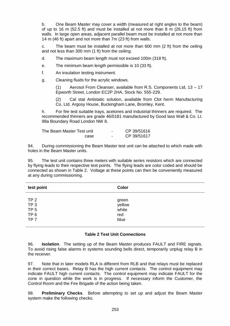
b. One Beam Master may cover a width (measured at right angles to the beam) of up to 16 m (52.5 ft) and must be installed at not more than 8 m (26.15 ft) from walls. In large open areas, adjacent parallel beam must be installed at not more than 14 m (46 ft) apart and not more than 7m (23 ft) from walls.
c. The beam must be installed at not more than 600 mm (2 ft) from the ceiling and not less than 300 mm (1 ft) from the ceiling.
d. The maximum beam length must not exceed 100m (318 ft).
e. The minimum beam length permissible is 10 (33 ft).
f. An insulation testing instrument.
g. Cleaning fluids for the acrylic windows.
(1) Aerosol From Cleanser, available from R.S. Components Ltd, 13 – 17 Epworth Street, London EC2P 2HA, Stock No. 555-229.
(2) Cal stat Antistatic solution, available from Clot herm Manufacturing Co. Ltd. Argosy House, Buckingham Lane, Bromley, Kent.
h. For fire test suitable trays, acetones and industrial thinners are required. The recommended thinners are grade 46/0181 manufactured by Good lass Wall & Co. Lt. 98a Boundary Road London NW 8.
The Beam Master Test unit - CP 39/51616 case - CP 39/51617 94. During commissioning the Beam Master test unit can be attached to which made with holes in the Beam Master units. 95. The test unit contains three meters with suitable series resistors which are connected by flying leads to their respective test points. The flying leads are color coded and should be connected as shown in Table 2. Voltage at these points can then be conveniently measured at any during commissioning.
test point Color
TP 2 TP 3 TP 5 TP 6 TP 7
green yellow white red blue
Table 2 Test Unit Connections
96. Isolation. The setting up of the Beam Master produces FAULT and FIRE signals.
To avoid rising false alarms in systems sounding bells direct, temporarily unplug relay B in the receiver. 97. Note that in later models RLA is different from RLB and that relays must be replaced in their correct bases. Relay B has the high current contacts. The control equipment may indicate FAULT high current contacts. The control equipment may indicate FAULT for the zone in question while the work is in progress. If necessary inform the Customer, the Control Room and the Fire Brigade of the action being taken. 98. Preliminary Checks. Before attempting to set up and adjust the Beam Master
system make the following checks.

254
a. Check that the wiring connection is correct according to a wiring diagram for the installation and that the connections are secure. The connector are given in Table 3 – 5 See also connection to fault and fire relay.
b. Check that both plug-in circuit boards in the receiver are correctly positioned and pressed in firmly.
c. Check the insulation of the system to earth with the insulation testing instrument.
d. Disconnect the positive and negative supplies to the emitter and receiver.
e. Apply voltage to the supply lines and check for polarity and continuity.
f. Connect supplies to emitter and receiver.
g. Check that the RESET switch in the receiver is in the ON position. The RESET switch is screening printed SW1 on the PCB. The ON position is marked POS 2 on the body of the switch, and it is the position in which the slide button is pushed away from the lens.
h. Check that the voltage supplies to both units are adequate. Note: Normal system supply undercharged conditions is derived from a float charged 12 cell lead acid batteries, giving 27.5 volts. Under mains failure conditions this quickly falls to 24 volts and remains substantially above 23 volts for the calculated standby period. The battery is considered to be exhausted when the voltage has dropped to 21.2 volts. The volt drop to the units must be too great. When the mains supply has failed the batteries have supported the system for the specified standby period, the voltage sat the units must still be at least 19 volts. This usually means that the maximum voltage drop on the cable run between the battery charger, control equipment and the Beam Master is 2.5 volts.
In the rage 21.5 to 19 V the Beam Master operates but at reduced sensitivity.
i. Check that either the FAULT or SYSTEM HEALTHY (CLEAR) lamp is lit. If neither lamp is lit check, that they are not faulty and are screwed in firmly. Also check the SMOKE and HEAT lamps in a similar way. Check the fuse is screwed in firmly.
j. Check that any temporary paper covers attached is inside or outside of the windows of the units is peeled off and that the windows are clean. If the windows are dirty clean as follows:
(1) Spray acrylic surfaces from a distance of approximately 154 mm (6.0 in), with Aerosol Foam Cleanser. Wait until it foams and wipe clean dry with a soft cotton cloth.
(2) Spray or apply Clots at with a soft cotton cloth dry and polish, never use abrasive cleaning materials.
Emitter: input connections on TB2.
Connection on TB2 Function
1 2 3 4
24 V d.c. positive 24 V d.c. positive 24 V d.c. positive 24 V d.c. positive
Table 3 Emitter: Input Connections

255
99. Receiver: Input and Output Connections On TB1. The receiver input and output connections are given in Table 4. Although the connections have remain unchanged the function of the fault relay, and its rating, changed from serial number 553. The fault relay contacts also became clean at the time. These changes are explained in connection to fault and relay, there has also been a change in the rating of the fire relay contacts, see Modification Status.
Connection on TB1 Function
1. FAULT relay, RLA, changeover contact
2. FAULT relay, RLA normally open contact
3. FAULT relay, RLA normally close contact
4. Not connected
5. FIRE relay, RLB, changeover contact
6. FIRE relay, RLB, normally open contact
7. FIRE relay, RLB, normally closed contact
8. Supply negative
9. Supply positive
10. Supply positive
11. Supply negative
12. Supply negative
13. Switch to negative supply line under FAULT condition
14. Switch to negative supply line under SMOKE condition
15. Switch to negative supply line under FIRE condition
Note 1 in the power CLEAR condition TB1, 1 is connected to TB1, 2 since RLA is energized. 100. Repeat Indicator. Input and output connections are made to a 12 – way connector
block. The connectors are not numbered but marked as in Table 5.
Number Marking Remarks
1 +VE 2 +VE 3 YI No internal connection 4 +RX 5 TP 6 FIRE 7 FIRE 8 FAULT 9 y2 No internal connection 10 -RX 11 -VE 12 -VE
Table 5 Repeat Indicator Connection

256
101. Connection To Fault And Fire Relays. The changes to the fault and fire relay circuitry which were introduced at serial number 553 are summarized in Figure 7.4.4. 102. In receivers of serial number less than 533 the fault relay is energized for only a short time following detection of a fault condition, i.e. on the terminal block, connector 1 is briefly to 2 and then re-connected to 3. The relay contacts are internally connected to other components. It is possible to change this mode of operation to that of continuous energization during SYSTEM HEALTHY (CLEAR) CONDITIONS, SEE Modification Status. 103. Aligning the Beam. The lens assemblies in the emitter and receiver are fitted with
similar adjustments. These are the milled adjusting screws (see Figures 2.2 and 2.3) which move the lenses in horizontal and vertical directions. Focusing is pre-set in the factory. The alignment takes the from of a preliminary adjustment followed by final adjustment making use of the pre-amplifier in the receiver. 104. Preliminary Alignment. Before leaving the emitter and receiver optical assemblies
are adjusted so that the infra-red beam leaves or enters the units along a line normal to the base. This means that if the units are mounted on nominally flat parallel surface there is a good chance that they will be sufficiently well aligned to obtain an initial signal. In this case proceed to Aligning the beam. Otherwise make a preliminary alignment as follows: 105. Place a lamp with a powerful beam in front of the emitter with the beam directed towards the receiver. Using a small piece of paper locate the pinpoint of light focused behind the receiver lance. Adjust the position of the lens until the pinpoint of light to confuse the light with what from other sources. It may be necessary to turn off other lights. 106. Now place the lamp in front of the receiver and adjust the position of the emitter lens until the light is focused on the centre of the LED. 107. When light is falling on either the photo-transistor or the LED chips it is often possible to see a reflected glow of ruby light. 108. Note on Voltage Measurements. Some of the voltage to be measured are at
relatively high impedance points and are therefore reduced to some extent when the voltmeter is connected. For this reason the voltmeter used should have an impedance of at least 20,000 ohms per volt. This is also the impedance of the there meters in the Beam Master Test unit. 109. In the following the corresponding voltages which would be ready by a digital voltmeter, which has much higher impedance, are enclosed in brackets when the difference is significant. All meter readings are made on d.c. ranges. 110. Final Beam Alignment:
a. Connect the Beam Master test unit or alternatively connect a meter to TP5 (+ve) and TP7 (-ve). This reading is known as the calibration voltage because it is noted and subsequently measured to check the beam stability.
b. VRI is the gain control. Turn it to maximum, which is fully clockwise viewed from the component side of the board.
c. By moving the receiver lens in a scanning motion using the milled adjusting screw it should be possible to pick up a signal and maximize it. The meter reading should be kept below 5 V (6 V) by turning down VRI, and the scanning motion resumed.
d. Check that the signal originates from the emitter by obscuring the beam at that end. If it does not, repeat from Preliminary Alignment.

257
e. A suitable voltmeter is then connected across the extra core and the negative supply (terminal 3 or 4 in the emitter), and the lens is adjusted to maximize the voltage reading. Alternatively a second person can be employed at the receiver continuously communicating the voltage whilst the other person adjusts the lens position for a maximum voltage. A walkie-talkie or intercom set is useful for the purpose. During this process keep the voltage below 5 V by turning VR1 down.
f. Tap the lens to ensure it is stable. Insulate the end of the spare core.
g. Replace the cover with the acrylic window on the emitter.
h. Optimize the alignment of the lens in the receiver. Using the knurled screw, adjust the position of the receiver lens until the voltage reading across TP5 and TP7 is maximized, keeping the voltage under 5 V.
i. Tap the lens to ensure it is stable.
j. Remove the spare core from TP5 and insulate the end.
k. All receivers are supplied with an aperture plate which should be fitted in front of the receiver and/or emitter lenses if the beam length is less than 20 m. The stops off part of the beam so that the intensity at the photo-transistor is in suitable range. This makes VR1 easier to adjust.
111. Checking the Flooding Diode. The flooding diode is situated behind the receiver
lens and illuminates the photo-transistor. This gives the photo-transistor an optical bias and increases its sensitivity to the infra-red pulses of the beam. If the flooding diode is inoperative or misaligned, false SMOKE alarms may be expected after dark. The flooding diode is connected to terminal strip TS3 which is close to the optical assembly. See Fig 8.
a. Check that the flooding diode is not obscuring the beam.
b. Connect a meter between TS3/1 (+ve) and TS3/4 (-ve). When all light reaching the photo-transistor from other sources is obscured with the reading should be between 0.3V and 2 V (0.1 V and 1 V).
Figure 8. Location of TS3
258
112. Setting and Checking the Trigger levels. After pre-amplification a voltage which is a measure of the height of the pulses is generated and processed in separate FAULT, HEAT and SMPKE channels.
113. The HEAT and SMOKE channels subsequently control the same FIRE relay. 114. Checking the FAULT Trigger Level. The FAULT trigger level is factory set and
should only require checking as follows: 115. Progressively reduce the calibration voltage using VRI and note that the signal from CLEAR TO fault within range of 1.4 to 0.6 v, or for later models at the voltage specified on the calibration label.
NOTE: VR3 is present and the initial adjustment lost for any reason:
a. Connect a meter between TP8 and TP6 and adjust VR# until a reading of I.C + 0.2V is obtained. Seal VR3 with silicone rubber.
b. With a 20 k/V or 30 k /V meter between TP 5 and SMOKE or HEAT signals resulting.
c. Adjust RV4 until the fault and system healthy lamps are on the point of switching over.
d. Seal RV4 with a dab of silicone rubber.
e. Setting the calibration voltage.
f. Set the calibration voltage to 5.9 C.
NOTE: To enable the engineer to determine whether the calibration voltage is
falling at a significant rate, it should be recorded on a label inside the unit together with the details of the voltmeter (ohms/volt and voltage range).
116. Setting the HEAT Trigger Level. The HEART channel is sensitive to fluctuations in
the received beam and latches the FIRE relay within 10 seconds of the present level being reached.
a. Connect a voltmeter between TP2 (+ve) and TP7 (-ve). This voltage is a measure of the thermal turbulence in the air traversed by the beam.
NOTE: With no thermal turbulence, the voltage reading across TP2 and TP7 would be about 3V. Under many site conditions the ambient or background turbulence gives a voltage reading of about 6 V but in certain conditions (e.g. where three are pendant ceiling heaters) the voltage may be as high as 10 or 11 V.
b. A judgment has to be made for every installation as to the setting of the HEAT trigger level. Observe the fluctuation in the turbulence occurring and consider the turbulence could increase in the future (e.g. due to different seasons, switching of heating or opening of large exterior doors).
c. Establish the maximum reading occurring over a few minutes. The longer the period of observation the more reliable the observed maximum voltage will be.
d. Decide on a suitable HEAT trigger level. Set the trigger level between 1.5 and 4.5 V above the maximum observed in (c). If it is thought that the turbulence is going to remain fairly steady in future and maximum heat sensitivity is required, set the trigger level at 1.5 V above the maximum observed. If it is thought that the turbulence is unsteady and may well increase beyond the maximum observed in the future, then the trigger level the degree of future expected stability in the thermal turbulence, the trigger level may be set at any point within the 1.5 V to 4.5 V range above the maximum observed ambient thermal turbulence.

259
e. If the Beam Master Test unit is not in use connect a second voltmeter between TP3 (+ve) and TP7 (-ve). The normal voltage at TP3 is about 20V and fall when the thermal turbulence exceeds the heat channel trigger level. The second meter is necessary to signify the moment at which the trigger level is exceeded because there is a delay before the HEAT lamp is lit.
f. Set the desired HEAT trigger level using VR2. To do so artificially modulate the beam by waving the fingers of an outstretched hand (or by oscillating the thumb) through the beam. This causes the voltage at TP2 to increase. By carefully modulating the beam at the required rate, hold the voltage at TP2 at the required trigger level. Now turn potentiometer VR2 until the voltage at TP3 just begins to fall. The HEAT trigger point has now been set.
g. Check that the threshold is correctly set by raising the volts on TP2 above the required level. The volts on TP3 drop to the region of 5 V. Allow the volts on TP2 to fall and note a corresponding increase on TP3. At the time the volts on TP3 reach the maximum, TP2 volt should be at the chosen threshold level. If this is not the case repeat from e).
h. Re set the unit by the local RESET switch. The switch has to be left in the OFF position for at least 30 seconds to allow a time delay capacitor to discharge. Then switch back to the ON position.
i. To check the serviceability of subsequent circuitry in the channel, allow the reading on TP2 to fall back to ambient level, then artificially increase the reading by modulating the beam, until it is fractionally above the required trigger level, the red HEAT lamp light up within 10 seconds.
i. Seal VR2, and reset the receiver. 117. Checking the SMOKE Sensitivity and the SMOKE Channel:
a. Measure the calibration voltage with a meter connected across TP5 and TP7.
b. Obscure part of the beam until the calibration voltage is reduced by 60% (i.e. to 2 V if the calibration volts are 5 V). The SMOKE lamp should illuminate within 5 seconds.
c. Alternatively the 60% and 40% filters specified List of Tools and Facilities may be used in a go/no-go test.
d. It is possible to change the smoke sensitivity from the 50% as supplied to 25% obscuration. To change the sensitivity requires the changing of a resistor on PCBI using a soldering iron. Switch OFF the supply, remote PBBI. Change resistor R12 (which is normally 12 K) to 5K6 for 25% obscuration, approximately. Replace PCBI, switch ON. Check the new sensitivity level.
e. Reset the unit by the local RESET switch. 118. Completion of Adjustments and Checking:
a. Disconnect all meters.
b. Connect the Beam Master to alarm system by plugging in relay B or making good any connections removed in the control equipment in Para ISOLATION above. If relay B was removed modulate the beam in the manner of Section SETTING THE HEAT TRIGGER LEVEL to check the correct latching via the HEAT channel. Reset, wait 3 minutes and then gradually obscure the beam to check for correct latching of the relay via the SMOKE channel. In each case alarm bells should ring. If connections to HA or HM were broken perform similar checks noting correct effect on the control equipment. In addition simulate FAULT conditions by obscuring the beam and observing the effect.
c. Replace the receiver cover.

260
d. Note that full commissioning includes a check at 1 week; see System Check One Week after Installation. Three-monthly checks should then the instigated as part of the regular service procedure.
119. System Check One Week after Installation. One remote sites special arrangement may be made with the customer with regard to this check. 120. After the system has been in commission for one week a check should be made to ascertain that no shift in beam alignment has occurred. If everything is satisfactory the calibration voltage between TP5 and TP7 will be within plus or minus o.5 V of the value logged on the calibration label during commissioning. If this is not the case try to find the cause. Check that the windows are still clean. If a small change in the position of the receiver or emitter lens results in an increase in the calibration voltage the beam alignment has drifted, otherwise the cause is either electronic or due to haze. 121. Any change to be made in the mounting of the units should be carried out before the final realignment. 122. If any changes have to be made the commissioning routine should be repeated, including beam alignment and the setting of the FAULT, HEAT and SMOKE trigger levels. The system should then be re-checked after a further week. 123. Fire Tests. The commissioning requirement may include full scale fire testing.
124. Before these tests are carried out is should be ascertained that they do not in themselves represent a fire hazard and that they do not contravene any of the site safety or insurance regulations. Written permission must be obtained from the side security officer or other suitable authorized personnel. These tests should be carried out in the presence of at least two people who are experienced in the use of fire extinguishers, and suitable extinguishers should be available. 125. The full scale fire tests are in two parts as described below. 126. Heat Test. Depending on the ceiling height, beam length and ambient level of
thermal turbulence, fires of different size are appropriate. 127. The heat, test should take the form of an acetone fire burning in a strongly constructed leak-free metal tray which, where necessary, should be well insulated from the floor and should be places not less than 2 m (6.6 ft) from any flammable material. The tray should have a wall depth of not less than 150 mm (5.91 in) and should be lit by throwing in a 25 mm (0.98 in), the acetone should be lit by throwing in a lighted match or paper spill. Under no circumstances should the fire be lit by match or spill held in the hand. The maximum tray size for say a 60 m (197 ft) beam under a 10 m (32.8 ft) high ceiling is not grater than 1.2 x 0.6 m (3.9 x 2 ft). For 3 m (9.8 ft) high ceilings a 0.3 m (0.98 x 0.98 ft) tray should be adequate. The customer may request fuels other than acetone. 128. Detection times should normally be 1 minute or less. 129. User Instruction, Precaution. Beam Master Fire detectors of other types in systems of varying complexity. When a Beam Master is a part of a complex system, and a control panel is in use, the Instructions Manual for that system should be consulted. The precautions given here apply generally but with particular reference to Beam Master Equipment.

261
a. Each fire detection system is individually designed to meet the requirements of the protected premises at the time of installation. Chubb Fire must be consulted before hand and however trivial they may seem. Failure to observe these requirements may reduce the efficiency of the system, and render any F.O.C. certificate or similar void.
b. Furniture, storage racks and goods must be placed to allow a space of at least two feet below each beam, there should not be similar obstruction within one foot of the ceiling of the protected zone.
c. Under no circumstances should any fire detection equipment be opened or wiring interfered with. Failure to observe these requirements may render all F.O.C. certificates and other approvals void.
d. For efficient operation and ease of servicing, free access must be available at all times to every component and unit of the system. The front of battery cabinets must be kept clear of obstructions at all times to maintain adequate ventilation of the cells.
e. Chubb Automatic Fire Detection and Alarm Equipment must not be painted or renovated in any manner whatsoever without previous reference to Chubb Service Department.
f. Cleaning of detectors and associated equipment is a specialized process and Chubb Fire recommend that it is undertaken by the Service Department. Component identification marks and plates must not be defaced nor obliterated in any manner whatsoever. It is recommended that no conduit or fitting associated with the system should be rendered over nor otherwise concealed.
g. Except by failure of the public electricity supply or during routine test, the a.c. feed to the system must not be interrupted.
130. Damage to Equipment. If any part of the system sustains damage it is
recommended that Chubb Fire should be consulted so that they can evaluate and make good. 131. Procedure after a Fire:
a. When the fire has been put out, it is preferable that the senior Fire Brigade Officer or similar responsible Official should give his consent before the Beam Master is reset. Before attempting to reset, ventilate the affected area to disperse all smoke or heat that would re-initiate the FIRE alarm signal, and inspect all detector units and associated cables within the affected zone for evidence of damage by fire or discoloration by smoke. Reset the system by one of the methods described in Para RESETTING THE SYSTEM.
b. Accurately log the time, date and details of the fire. Log the time and date of the reset procedure.
132. Resetting the System. If the fire alarm occurred in known circumstances the system may be reset by one of the methods described in this section. Before resetting after a fire, however refer Para PROCEDURE AFTER FIRE. 133. If repeat indicator are in use turn the key switch of the indicator which has its FIRE lamp lit to the RESET position for a few seconds. If control equipment is in use, reset at the control panel. 134. If neither repeat indicator nor control equipment is installed it is necessary to switch off the system momentarily and then restore power. Note that following and method of resetting if any lamp other than the green lamp is lit the system has damage and Chubb Fire should be informed.
262
135. Fault Alarm:
a. If control equipment is in use, refer to the Instruction Manual for that equipment.
b. Check that the beam is not mechanically obstructed.
c. Check that the power supply has not been interrupted.
d. FAULT alarms due to b or c reset automatically at the Beam Master equipment once the cause is removed, but have to be manually reset at the control panel.
e. Accurately log the time, date and details of the FAULT condition. Log the time date of the reset procedure.
136. Maintenance At Servicing Procedures – Equipment. The recommended equipment for Maintenance and Servicing is the same as that for commissioning. 137. System Check Tree Month after Commissioning and Every Three Months There After. Repeat the routing in commissioning three months after the system has been
commissioned. 138. Do not change the beam alignment if the calibration voltage is within limits. Do not change trigger if they are within limits. The windows of the emitter and receiver should be clean if necessary. The HEAT trigger level may be altered if appropriate, during the routine. 139. Three Monthly Service Procedure. Beam Masters should be given functional test
every three months, as detailed below working at the receiver unit.
a. Place a 20% filter against the window in line with the lens for 10 seconds. No signal is generated.
b. Place a 60% filter against the window in line with the lens 10 seconds. Check that the SMOKE lamp is illuminated and that a FIRE signal is transmitted.
c. Before resetting the unit, completely obscure the beam and check that the amber FAULT lamp is illuminated but that the SMOKE signal is retained.
d. Reset the Beam Master and any associated control equipment.
e. Simulate heat modulation by waving the outstretched fingers of one hand through the beam. Check the red HEAT LAMP IS ILLUMINATED AND THAT A fire SIGNAL IS TRANSMITTED.
f. Reset the Beam Master and any associated control equipment.
g. Completely is sure the beam. Check that the amber FAULT lamp is transmitted. No smoke signal should be generated.
h. Check on removing the obscuration that the Beam Master resets if salt. Reset any control equipment with latching fault circuits.
i. If any of the above fail, clean the windows of the emitter and the receiver and repeat a to g. The windows are made of acrylic material and should only be cleaned as described in TOOLS AND FACILITIES item (L).
j. Open the receiver and replace the open SYSTEM HEALTHY (CLEAR) LAMP IF OF THE FILAMENT TYPE.
k. Check the calibration voltage measured between TP5 and TP7. If the voltage has fallen by more than 0.5 V from the original setting, this must be restored by re-adjusting the emitter and receiver lens alignment (replace emitter front cover immediately after lens adjustment), turning up VR1 and re-sealing it with silicone rubber.

263
l. If the calibration voltage cannot be restored by the above procedures the units should be replaced.
m. If false heat alarms have been reported, increase the setting of the heat trigger level by 1 to 2 V.
n. The service on the Beam Master is now complete.
o. The service on the Beam Master is now complete. 140. Technical Information. The information in this chapter refers to the standard Beam Master Mod 2 equipment. Special equipment have been supplied from time to time to suit unusual local conditions, the parameters of which differ from those stated in this chapter.