Embed Size (px)
Citation preview

Automated Trash Can
Michael Gao, Aditya Sule, and Eshwar Cheekati
ECE 445 Design Document – Spring 2017

1 Introduction
1.1 Objective
Trash management is an integral part of our daily lives. Just by doing simple everyday tasks like
cooking or cleaning, we generate a substantial amount of waste. However, without proper
monitoring, waste can stagnate in our trash cans, leading to unpleasant odors that spread throughout
the household. A possible solution is to take out the trash frequently, but that may also be wasteful if
the trash can is mostly empty. Likewise, different amounts of waste are generated day by day, so
predicting exactly when to take out the trash becomes more difficult. Moreover, since the average
person generates roughly 4.6 pounds of trash a day[1], the frequency in which we need to check and
maintain our trash cans becomes greater. This becomes even more difficult considering the number
of trash cans in a household. We can expect a kitchen trash can, individual room waste bins, and
bathroom waste bins.
Our goal is to improve the trash can by automating parts of the trash management process. We will
integrate a microcontroller chip, sensors, as well as a DC stepper motor connected to wheels to a
small waste bin. Using an ultrasonic sensor placed on the lid of our trash can, we can detect the level
of waste. When our waste level passes a certain threshold, our microcontroller sends a notification to
our phones via wifi. The trash can then move itself to the door using a predetermined route. By doing
so, we eliminate the need to constantly check the trash and provide a convenient reminder when the
trash is full. If we see that the trash can is by the door, we know we can take out the trash on the way
out. By doing these things, we essentially have an IoT trash can that simplifies the majority of trash
management.
1.2 Background
Existing attempts to automate the trash can are few and far between. Ecube Labs provides a trash
automation system for municipal trash management. This is for much larger scale deployments and is
not geared towards the average consumer. Likewise, these existing large scale attempts focus
primarily on the detection aspect of waste management, so that garbage trucks can better plan their
pickup routes.
Our system aims to be more readily available to an average consumer. Likewise, our focus shifts
towards improving the notification system beyond simple phone messages. By having the trash can
automatically navigate to the door, we are conveniently reminded to take out the trash on the way.
Furthermore, the navigational aspect can be expanded for use in suburban homes where waste
pickup occurs the same day every week. Our system could potentially be configured to automatically
move itself to the curb prior to pickup and move itself back afterwards. This completely removes the
need to manually do a weekly task for suburban homeowners.

1.3 High Level Requirements
● Microcontroller must be able to reliably detect when the trash can is over 80% full.
● With a completely unobstructed path, the trash can should be able to navigate to the door
with 90% accuracy. With the presence of minor obstacles, the trash can should be able to
navigate to the door with 70% accuracy.
2 Design
Figure 1: Side Profile

Figure 2: Front Profile
Figure 3: Cutout Profile

Figure 4: Block Diagram
2.1 Power Supply
First, it would be a good idea to calculate an estimate of what our power requirements would be. We
can calculate the power required to drive the motors using some basic mechanics. There are two
ballpark numbers here that we are interested in. The first is the power required to keep the trashcan
in motion, and the second is the power required to get the trashcan moving in the first place. Before
we try to estimate those numbers, let us consider the following assumptions. Say that the maximum

mass of the trashcan, including all the electronics is about . We estimate the coefficient of 10 kgm =
rolling friction between the wheels of the trashcan and the flooring to be .[2] Let us also.6μ = 0
assume that the trashcan is trying to move up an incline of . Let the radius of the wheels be°θ = 3
Let us also assume that our motors run with an efficiency of 60%. cm.r = 5
Figure 5: Wheel on incline
Let us calculate the power required to keep the trashcan moving at a constant speed of Tocm/s.v = 5
do that we must first calculate the torque required to rotate the wheel. The force here will be
provided by the friction between the wheel and the floor. Balancing the forces in the x direction, we
get , where f is friction, and F is the force required to keep the object moving. Theg sin(θ) Ff +m =
force of friction here is . The torque is therefore, . Theg cos(θ) μf = m r g (sin(θ) cos(θ)) rτ = f = m + μ
mechanical power required to keep the wheel moving is where is the angular velocityωP = τ /rω = v
of the wheels. Plugging in all the numbers we can get an estimate on the power to be .4W .P = 3
Factoring in the efficiency of the motors, the real power required will be about 5.5W.
We know that the power required to get the trashcan moving will be higher than this number, we can
accelerate slowly to this speed and reduce the angular speed requirements by using an appropriate
gear assembly. Since we will have two driving motors, each motor will draw about half of that power.
Using these rough numbers, we can now state the following power supply requirements for our
project.
2.1.1 NiMH battery

Judging by the power requirements. We will require a driving battery pack that can supply at least
12V, with a current supply of at least 500mA and up to 1.5A.
Requirements Verification
1. 14 V fully charge voltage. 2. Can supply 1.5A current. 3. Re-chargeable
1. Voltage across battery can be measured with a voltmeter when fully charged.
2. By providing a resistance load across the battery, current through the resistor can be measured to verify it.
2.1.3 NiMH charger
We will use a commercially available charger for our battery pack. The charger should not overheat
the battery while charging. Should be able to bring the battery back up to 12V.
Requirements Verification
1. 14.4 V charger. 2. Charge current of no greater than 3A 3. Low trickle charging rate 4. Does not charge battery when too hot
1. Measure the voltage across the battery after it is fully charged.
2. Verify charging current with Ammeter. 3. Monitor the the battery when charging.
2.1.4 Voltage Regulator

Figure 6
We will be using a voltage regulator to generate a clean 5V DC signal to feed into the microcontroller
chip and then regulate the 5V to 3.3V to feed into the sensors. The L7805 chip that generates a fixed
output voltage of 5V with a max output current of 1.5A will be used. A .33uF capacitor is connected
between the voltage source (battery) and the input pin of the regulator to filter out any noise from
the battery. [3] Likewise, the output of the regulator is also cleaned up by the .1uF to produce a clear
regulated DC signal. The regulator is also susceptible to heating due to the power dissipation so the
requirement of a heat sink will be discussed in the tolerance analysis section. Similarly, the LD1117 is
connected from the 5V output of the L7805 to regulate the voltage to 3.3 and it is connected with its
respective capacitance values to generate a clean signal.
Requirements Verification
1. Capacitors have .33uF, .1uF, 10uF 2. Output of regulator is 5V and 3.3V 3. Protect against battery being place in
reverse by user
1. Measure capacitance using multimeters
2. Set up circuit as provided by Figure 6 and measure potential at Vout
3. A jack will be provided for the battery so the user will be forced to place the battery in the right direction
2.2 Control Unit
The control unit is a microcontroller that manages the data coming from the sensors and controls the
stepper motor through the driver. It also interfaces with our wifi module to allow for communication
with our android phone application.
2.2.1 Microcontroller
The microcontroller we will using is the ATMega328p. This is the same MCU that is used in the
Arduino uno. We chose this model due to the wide amount of compatibility it has with sensors and
the substantial documentation available on the usage of ATMega328p. It takes in input data from the
ultrasonic sensors and connects to the drivers that control the step motors. The recommended
operational voltage for the ATMega328p is 5v. We will also being supplying an external 16MHz clock.
Requirements Verification

1. The microcontroller must be able to
read input data from every sensor at the
same time.
1. Write a test program that monitors output data from all the sensors. Run the program and check to see if all sensors are being read concurrently.
2.2.1 FTDI Serial to USB Convertor
To program the microcontroller we will need to an interface between a computer and our
ATMega328p. ATMega328p supports RS232 serial communication but since RS232 ports are rare on
computers, we will instead use a FTDI Serial to USB convertor to allow our microcontroller to be
programmed via USB.
Requirements Verification
1. Entire USB protocol handled on FTDI chip.
1. When plugged into a computer, we should be able to communicate with our MCU via USB without additional firmware.
2.3 Sensor Unit

Figure 7: Schematic
The sensor unit contains the two ultrasonic sensors and four infrared sensors. The first ultrasonic
sensor is placed on the lid of the trash can and is used to detect trash level. The second ultrasonic
sensor is placed on the front of the trash can as a proximity sensor for obstacles. This will be
integrated into our navigation so that we can support simple obstacle avoidance. The four infrared
sensors will be used to follow a line on the floor (dark tape). Two will be placed in the middle and the
other two infrared will be placed wider out for better navigation of the tape.
2.3.1 Ultrasonic Sensor
The ultrasonic sensor unit we will be using is the HC-SR04. This ranging sensor has a detection
distance from 2cm to 4m with up to 3mm accuracy. It operates on 5V DC and 15mA. [4] The sensor
has 4 pins: Vcc, Trig, Echo and GND. A pulse is sent to the trig pin to start the ranging and the echo pin
returns a signal when the ranging is complete. By measuring the interval between the start of the trig
signal and the received echo signal, we can measure distance (range to the current trash level or
object in front of trash can)[3].

Requirements Verification
1. Must be able to detect an object 10cm away within 2cm of accuracy.
2. Must be able to detect that an object is 10cm away within 1 second.
1. Place objects 10cm from HC-SR04 and check measured ranging value.
2. Place an object 10cm from HC-SR04. Save a timestamp when trigger signal is sent and a separate time stamp when echo signal is received. If the difference between timestamps is less than 1 second, then our requirement is met.
2.3.2 Infrared Sensor
We will be using the SEN-11769 infrared sensor. Four will be placed on the bottom of our chassis
facing the ground with the IR transmitter and receiver facing downwards, They will be placed 1 inch
apart. By using these infrared sensors, we can allow our automated trash can to follow a dark line on
the floor.
By implementing the behavior described above, our trash can essentially tries to keep the dark tape
within the bounds of the left and right IR sensor. By doing so the trash can follows the tape, which we
will use to navigate our trash can towards the door.
Requirements Verification
1. The IR sensor reads at least a 25% difference in measurements between white paper and black printer ink on paper. This measurement is made when placed 40mm above the paper.
1. Printer Paper Test a. Print black strips on regular
printer paper. b. Place the IR sensor 40mm above
the white section of the paper for 1 minute.
c. Take the average of all reads from that minute.
d. Perform the same measurements with the black ink portion of the sheet.
e. Calculate the percentage difference in averages.

2.4 Motor Unit
Figure 8: Motor Schematic ([5])
2.4.1 Stepper Motor
A stepper motor is used over a DC motor because stepper motors provide more torque with lower
angular velocity (rpm). Since our trash can can travel at low speeds (5cm/s) but the torque
requirements are high for it to be propelled forward (~2.5 Nm), using a stepper motor seemed
reasonable. The DC motor would’ve required an extra gear assembly with the right gear ratio to
obtain our required torque and it would’ve had an extremely high rpm which we don’t need. There
will be two stepper motors that will attach to the back two wheels of the trash can. The input
operating voltage for each motor is a recommended 12V DC and can handle a maximum input current
of 1.7A. To control the speed of the stepper motor, we can use the Arduino library “AccelStepper” and
code it through software. Furthermore, we will also be using a stepper motor driver to help precisely
control the motor. Each stepper motor will electrically connect to the driver and mechanically connect
to the axles for the wheels.

Requirements Verification
1. Each stepper motor should be able to provide 1.5Nm of torque
2. Total power output of the motor should be greater than 10W and less than 30W.
3. RPM should be > 16
1. To test the torque provided by the motor, a simple test can be set up. The motor shaft is connected to a horizontal shaft. The shaft length is known. The end of a shaft is connected to a spring balance, and the weight on the spring balance is recorded. The torque provided can be thus calculated.
2. RPM provided by the motor can be calculated by measuring the number of rotations of the wheel.
3. Power provided by the motor can be calculated by taking the product of angular velocity and torque.
2.4.2 Motor Driver
The motor driver is used to accurately control the stepper motor. We will be using the A4988 motor
driver since it’s specific to bipolar stepper motors and only requires 2 pins per driver on the Arduino.
The pin layout for the driver is specified by Figure 7. For the pins MS1, MS2, MS3, the driver has
internal pull-down resistors so when nothing is connected, they will all be low and this will result in a
full step in the motor. [5] A capacitor of 100uF will also be needed so the driver board can handle any
voltage spikes.
Requirements Verification
1. Capacitor > 100uF to handle voltage spikes
2. Interface between Arduino software and driver communication with motor works
1. Use multimeter to measure capacitance 2. Send 200 pulses through a for loop with
the Step-pin and observe the step motor make one full rotation
2.4.3 Wheels
Four wheels, two on the front and two on the back, will guide the trash can in navigation. The wheels
will be mounted on the lower platform. We need a simple 1:1 transfer gear to transfer power from

the gears to the wheels. The wheels will consist of thermoplastic silicone tires which will provide for
good traction.
Requirements Verification
1. Wheel diameter should be 6cm. 2. Wheel axle diameter should be
compatible with power transfer gear. 3. Wheel should provide enough traction.
1. Large measurements can be made using vernier calipers.
2. Small precise measurements can be made using a screw gauge.
3. Traction can be verified by adding a normal force on the wheel then attempting to rotate the wheel and making sure there is no slippage.
2.5 Wifi Unit
The wifi module we’ll be using is the ESP8266. This will be used to allow our trash can to be an IoT
device. Then using a computer or smartphone, we can send HTML requests to our trash can to query
sensor information or configure other trash can settings. x
Requirements Verification
1. Capable of connecting to 2.4GHz Wifi bands.
2. Can operate at 3.3V.
1. Connect to a 2.4 GHz wifi bands. 2. Provide 3.3V to VCC on HC05 and check
if attempts to pair are successful.
2.6 Chassis
The chassis will be constructed using plywood. Plywood is cheap, light and easily available material.
The chassis will consist of two boards of plywood. The upper level will be supported by 4 columns. The
motors, PCBs, arduino will be mounted on the lower level. We will attach the trashcan to the upper
level. We will cover the sides with sheets of plastic. The upper board can be detached from the lower
boards and its support struts for ease of maintenance. The wheels will be slightly offset, below the
lower board of plywood. There will be a small cutout in the lower level to allow for the power to be
transferred from above the lower level to the wheels.
Requirements Verification
1. Can support a weight of 15kg. 2. Dimensions match the base of the trash
can.
1. Simple stress test can be used by placing weights on the prototype to test for failure.
2. Measure the dimensions of the trashcan carefully before cutting out the plywood.
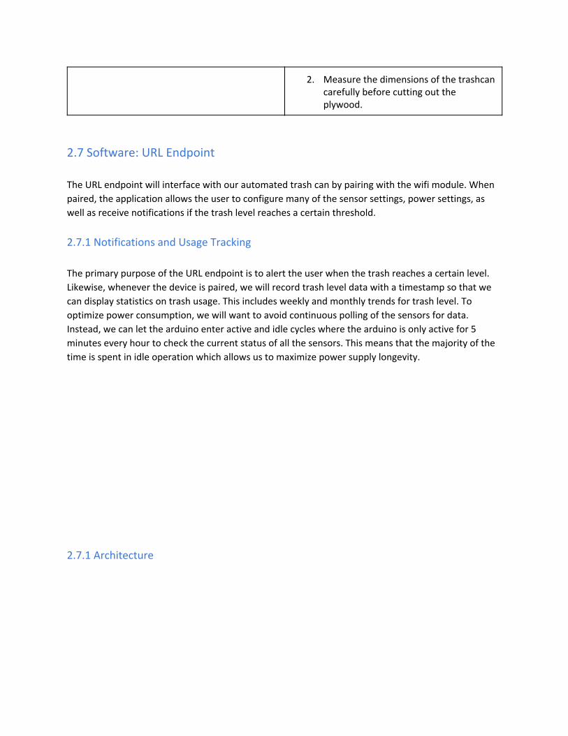
2.7 Software: URL Endpoint
The URL endpoint will interface with our automated trash can by pairing with the wifi module. When
paired, the application allows the user to configure many of the sensor settings, power settings, as
well as receive notifications if the trash level reaches a certain threshold.
2.7.1 Notifications and Usage Tracking
The primary purpose of the URL endpoint is to alert the user when the trash reaches a certain level.
Likewise, whenever the device is paired, we will record trash level data with a timestamp so that we
can display statistics on trash usage. This includes weekly and monthly trends for trash level. To
optimize power consumption, we will want to avoid continuous polling of the sensors for data.
Instead, we can let the arduino enter active and idle cycles where the arduino is only active for 5
minutes every hour to check the current status of all the sensors. This means that the majority of the
time is spent in idle operation which allows us to maximize power supply longevity.
2.7.1 Architecture

Figure 9: Software Architecture
Our wifi module sends HTTP post requests to populate the DB with sensor data. This data can then be
queried and viewed in the form of tables or charts from the UI for the URL endpoint. Users can also
use the UI to configure certain options such as:
● Trash Level Detector: we can set the threshold level for notifications
● Infrared Sensors: we can set the type of background surface (light background with black tape
vs dark background with white tape)
● Sensor polling rate: we can set the frequency in which we check for trash level. By increasing
this number, we also decrease our battery longevity.
These options are sent to the wifi module as a HTTP update request. The following is a flow diagram
to illustrate the general design of our wifi module-URL endpoint interface:

Figure 10: Endpoint Flow DIagram
2.6 Tolerance Analysis
We must maintain the core temperature of our voltage regulator below a certain temperature upper
bound. If the voltage regulator runs too hot, we would need a heatsink to dissipate the regular heat
into the surrounding area. We will assume the ambient temperature will be 25 °C but we want our
voltage regulator to be tolerant down to ambient temperatures of 18 °C (colder during the winter). To
determine if we need a heatsink, we must determine how the junction-to-ambient (total) thermal
resistance compares to the junction-to-case thermal resistance and junction-to-ambient thermal
resistance. [7]

The voltage regulator we are using is the L7812 with the following thermal resistances:
hermal Resistance junction o mbient θ 50 T − t − a = JA = W°C
hermal Resistance junction o ase θ 5 T − t − c = JC = W°C
Our supply outputs 12V DC and our voltage regulator downshifts that to 12V DC at 1.5 amps. The
power dissipation of the regulator is as follows:
(V ) PD = in − V out · Iout
12 ) .5 = ( − 5 · 1
0.5W = 1
Then with the power dissipation of the regulator, we can calculate the junction-to-ambient (total)
thermal resistance. The maximum operating junction temperature is 125 °C. Our ambient)(T J
temperature is 25 °C. So with this our thermal resistance is:
θJA(TOTAL) = PDT −TJ A
= 10.5125−25
.52 = 9 W°C
SInce our total junction-to-ambient thermal resistance is greater than the junction-to-case thermal
resistance and less than the junction-to-ambient thermal resistance, a heat sink will be necessary. To
calculate the thermal resistance rating needed for our heatsink we can use the follow calculation:
θSA = θJA(TOTAL) − θJC
5.52 = 9 −

= 4.52 W°C
However, since we want to be tolerant down to 18 °C, we will need a better heatsink to
compensate. Our new total junction-to-ambient thermal resistance is:
θJA(TOTAL) = PDT −TJ A
= 10.5125−18
0.2 = 1 W°C
So the rating of our heatsink should be:
θSA = θJA(TOTAL) − θJC
50.2 = 1 −
= 5.2 W°C
With a heatsink rated at 5.2 , we would be tolerant of ambient temperatures down to 18 °C. W
°C
3 Costs
We estimate our development costs to be $40/hour. Our team of three people will work 8
hours/week each. So for our 10 week design period, the cost would be:
2 weeks 11, 00 3 · $40hour · week
8 hours · 1 = $ 5
Our parts cost $210.76 in total.
Part Cost
ATMega328p $8.96
ESP8266 (Wifi) $6.95

CP2102 (FTDI) $7.00
4 x SEN-11769 (IR Sensor) $11.80
2 x HC-SR04 $7.90
Waste Bin $5.00
2 x A4988 Stepper Motor Driver $11.90
2 x Geared Bipolar Stepper Motor (RB-PHI-210) $88
12V Rechargeable NiMh Battery Pack $17.50
Battery Pack Charger $25
L7805 5V voltage regulator $0.75
Plywood $20
LD1117 3.3V voltage regulator $1
4 Schedule
Week Michael Aditya Eshwar
3/6 Design phone application
Assemble initial prototype for trash can. Coordinate with Esh for parts verification.
Verify parts to make sure they meet requirements
3/20 Implement pairing with android phone with bluetooth module. Continue implementing phone application.
Draft version 1 PCB design.
Implement trash fullness detector and proximity sensor.
3/27 Add sensor data from ultrasonic sensors to phone app.
Draft final version of PCB design.
Begin working on navigation system with IR sensors.
4/3 Allow navigation system to operate on
Design and add housing for trash level
Integrate basic collision avoidance

both dark and light floors. This feature should be configurable from the phone application.
sensor. into navigation system.
4/10 Begin final paper. Finalize prototype build.
Optimize battery longevity by modifying sensor default states.
4/17 Prepare for demonstration.
Peer review code for sensors and phone application.
Continue final paper.
5/1 Clean up application code and fix any remaining bugs.
FInish final paper Clean up application code for sensors and fix any remaining bugs.
This puts the total development costs at $11,691.
5 Ethics and Safety
In our project, we will strive to adhere to #1 in the IEEE code of ethics by taking responsibility for any
safety and welfare issues that any user of our product has. [9] Since the goal for our product is so that
it can be used wide-scale in any small room environment such as a college dorm room, the user base
will be large and the probability of a safety concern is greater. If any user informs us of any safety
concerns, we will address his or her concerns immediately and update our product accordingly as
according to #9 in the code of ethics. [9] We also hope to adhere to 1.3 in the ACM code of ethics by
always being honest and trustworthy in the construction of our product, analysis of the data for our
product, and feedback to users of our product.[10]
We address our current known safety concerns as follows. The trash can contains a NiMH battery
pack to power the electronics and motor. This comes with various safety concerns which we have
addressed as follows. We selected the NiMH batter over the Li-ion batteries as they are considerably
safer.[8] The battery is not as susceptible to physical damage as the Li-ion batteries are. Precautions
still need to be taken with this kind of battery to ensure that the battery doesn’t overheat. The
battery needs to be charged carefully as the battery is very susceptible to overcharging, and trickle
charging must be kept low. We will ensure that the battery does not overheat by installing a
thermocouple in the battery housing which cuts off the power drawn from the battery when
temperature is greater than 45C.
Another safety issue comes from the fact that the trash can potentially contain liquids or corrosive
substances that might damage our circuitry. We will make sure that the trash compartment is
completely isolated from the electronic compartment of the design.

Lastly, the intelligent trashcan can pose a threat to pets. We will ensure that this aspect is factored
into the navigation circuitry and that the trashcan will not move if it detects moving obstacles.
References
[1]"Garbage-- Solid Waste." Garbage-- Solid Waste. N.p., n.d. Web. 09 Feb. 2017.
[2]Vol. 7, No. 1, January 2012, and Issn 1819-6608. FRICTION COEFFICIENT OF RUBBER SLIDING
AGAINST FLOORING MATERIALS (n.d.): n. pag. Arpnjournals. ARPN, 1 Jan. 2012. Web. 9 Feb. 2017. [3] "How to Connect a Voltage Regulator in a Circuit." How to Connect a Voltage Regulator in a Circuit . N.p., n.d. Web. 24 Feb. 2017. [4]"Ultrasonic Sensor - HC-SR04." SEN-13959 - SparkFun Electronics. N.p., n.d. Web. 09 Feb. 2017. [5]Nedelkovski, Dejan S. "How To Control Stepper Motor with A4988 Driver and Arduino."HowToMechatronics . Mechatronics, 16 May 2016. Web. 22 Feb. 2017. [6]"BlueTooth-HC05-HC06-Modules-How-To." Arduino-info - BlueTooth-HC05-HC06-Modules-How-To.
N.p., n.d. Web. 09 Feb. 2017. [7]Vis, Peter J. "Heat Sink Voltage Regulator 7805." Heat Sink Voltage Regulator 7805 . N.p., n.d. Web. 21 Feb. 2017. [8]"BU-203: Nickel-based Batteries." Nickel-based Batteries Information – Battery University. N.p.,
n.d. Web. 24 Feb. 2017
[9] "IEEE IEEE Code of Ethics." IEEE - IEEE Code of Ethics . N.p., n.d. Web. 17 Mar. 2017. <http://www.ieee.org/about/corporate/governance/p7-8.html>. [10] "Code of Ethics." ACM Ethics . N.p., 29 July 2016. Web. 15 Mar. 2017. <http://ethics.acm.org/code-of-ethics/>.