Embed Size (px)
Citation preview

Master in Security and Mobile ComputingJune 2010Stig Frode Mjølsnes, ITEM
Submission date:Supervisor:
Norwegian University of Science and TechnologyDepartment of Telematics
Automated Security Analysis ofInfrastructure Clouds
Sören Bleikertz


Problem DescriptionThe importance of virtualized infrastructures and cloud computing is currently increasing rapidly.Virtual infrastructures allow servers, networks, and storage to be virtualized and shared betweendifferent users. Cloud computing generalizes and automates this approach such that users of adata center can request virtually any number of machines, networks, and storage whileprovisioning and scaling is fast and managed transparently by the provider.
The increasing complexity and multitenancy of such virtualized infrastructures can cause severesecurity problems due to possible misconfigurations, e.g. two different users have access to thesame storage, and the abstraction of cloud computing hinders the verification of policycompliance. An automated mechanism is required to handle these scenarios and IBM built aprototype for retrieving the configuration of virtual systems and performing certain securityanalysis on them.
The goal of this master thesis is to a) extend the prototype to public infrastructure clouds, e.g.Amazon WebServices, and to b) improve the overall security analysis of the discovered hybrid cloudconfiguration.
a) We are interested to investigate what possible security implications and problems publicinfrastructure clouds could have and how we can detect them with our analysis framework. Theprototype will be extended to handle discovery and isolation analysis of public infrastructureclouds.
b) The analysis improvements could be one or more of the following ones: Identifying the rootcause of a security problem in a fine-grained way; Comparison of configurations, e.g. desiredconfiguration and discovered one; Severity rating of security problems and security levels forconfigurations. We want to investigate if we can successfully detect misconfigurations and dopolicy compliance checks for private, public and hybrid cloud configurations, and if we can supportusers and providers of cloud computing in their security management.
Assignment given: 04. January 2010Supervisor: Stig Frode Mjølsnes, ITEM


Master’s Thesis
Automated Security Analysis ofInfrastructure Clouds
Sören Bleikertz
Department of Informatics andMathematical ModellingTechnical University of Denmark
Department of TelematicsNorwegian University ofScience and Technology
Supervisors:Prof. Christian W. ProbstTechnical University of DenmarkProf. Stig F. MjølsnesNorwegian University of Science and TechnologyDr. Matthias SchunterIBM Research - Zurich
June 2010


Abstract
Cloud computing has gained remarkable popularity in the recent years by awide spectrum of consumers, ranging from small start-ups to governments.However, its benefits in terms of flexibility, scalability, and low upfrontinvestments, are shadowed by security challenges which inhibit its adoption.In particular, these highly flexible but complex cloud computing environmentsare prone to misconfigurations leading to security incidents, e.g., erroneousexposure of services due to faulty network security configurations. In thisthesis we present a novel approach in the security assessment of multi-tierarchitectures deployed on infrastructure clouds such as Amazon EC2. Inorder to perform this assessment for the currently deployed configuration,we automated the process of extracting the configuration using the AmazonAPI and translating it into a generic data model for later analysis. In theassessment we focused on the reachability and vulnerability of services inthe virtual infrastructure, and presented a way for the visualization andautomated analysis based on reachability and attack graphs. We proposed aquery and policy language for the analysis which can be used to obtain insightsinto the configuration and to specify desired and undesired configurations.We have implemented the security assessment in a prototype and evaluated itfor practical and theoretical scenarios. Furthermore, a framework is presentedwhich allows the evaluation of configuration changes in the agile and dynamiccloud environments with regard to properties like vulnerabilities or expectedavailability. In case of a vulnerability perspective, this evaluation can be usedto monitor the security levels of the configuration over its lifetime and toindicate degradations.

Acknowledgments
I would like to thank my supervisors Matthias Schunter, Christian Probst,and Stig Mjølsnes for allowing me the freedom to pursue my own ideas anddirections, although also giving me valuable feedback and comments. Fur-thermore, I am grateful to the whole Security group of IBM Research Zurich,managed by Andreas Wespi, for supporting this thesis and hosting me for thethird time in a row. I am also very thankful to my colleagues who reviewedand provided feedback on this thesis: Animesh Trivedi, Rüdiger Kapitza,Ulrich Dangel, and Gregory Zaverucha. Finally, I would like to thank myfamily for supporting me throughout my studies.
Sören Bleikertz
Zürich, SwitzerlandJune 2010

Contents
1 Introduction 11.1 Motivation & Problem Statement . . . . . . . . . . . . . . . . 21.2 Scope . . . . . . . . . . . . . . . . . . . . . . . . . . . . . . . 21.3 Methodology . . . . . . . . . . . . . . . . . . . . . . . . . . . 31.4 Our Contributions . . . . . . . . . . . . . . . . . . . . . . . . 31.5 Thesis Outline . . . . . . . . . . . . . . . . . . . . . . . . . . . 4
2 Background 52.1 Cloud Computing . . . . . . . . . . . . . . . . . . . . . . . . . 52.2 Virtualization . . . . . . . . . . . . . . . . . . . . . . . . . . . 92.3 Amazon Web Services Architecture . . . . . . . . . . . . . . . 11
3 Literature Review 153.1 Virtual Machine Security . . . . . . . . . . . . . . . . . . . . . 153.2 Network Security Analysis . . . . . . . . . . . . . . . . . . . . 23
4 Existing Prototype: SAVE 294.1 Configuration Discovery . . . . . . . . . . . . . . . . . . . . . 294.2 Analysis . . . . . . . . . . . . . . . . . . . . . . . . . . . . . . 314.3 Examples . . . . . . . . . . . . . . . . . . . . . . . . . . . . . 31
5 Configuration Discovery for Public Infrastructure Clouds 345.1 Discovery & Data Model for Amazon . . . . . . . . . . . . . . 345.2 Integrated Model & Discovery for Infrastructure Clouds . . . . 36
6 Multi-tier Virtual Infrastructures in Public Clouds 376.1 Configuration Security Audits . . . . . . . . . . . . . . . . . . 386.2 Comparison of Deployment Methods . . . . . . . . . . . . . . 506.3 Analysis of Configuration Changes . . . . . . . . . . . . . . . 53
i

CONTENTS
7 Evaluation & Practical Results 617.1 Performance Evaluation . . . . . . . . . . . . . . . . . . . . . 617.2 Reachability Analysis Results . . . . . . . . . . . . . . . . . . 667.3 Attack Graph Analysis Results . . . . . . . . . . . . . . . . . 69
8 Outlook & Open Questions 728.1 Hybrid Cloud Analysis . . . . . . . . . . . . . . . . . . . . . . 728.2 Amazon Security Group Transformation . . . . . . . . . . . . 738.3 Design Tool . . . . . . . . . . . . . . . . . . . . . . . . . . . . 738.4 Complex Firewall Rules Analysis . . . . . . . . . . . . . . . . 738.5 SAVEly for Private Clouds . . . . . . . . . . . . . . . . . . . . 74
9 Conclusion 75
Bibliography 77
A Amazon EC2 Architecture Details 87A.1 Storage . . . . . . . . . . . . . . . . . . . . . . . . . . . . . . . 87A.2 Networking . . . . . . . . . . . . . . . . . . . . . . . . . . . . 88A.3 Domain Naming . . . . . . . . . . . . . . . . . . . . . . . . . . 88A.4 XenStore Dump . . . . . . . . . . . . . . . . . . . . . . . . . . 88
B Data Models 92B.1 Realization Model . . . . . . . . . . . . . . . . . . . . . . . . . 92B.2 Logical Model . . . . . . . . . . . . . . . . . . . . . . . . . . . 94B.3 Integrated Realization Model . . . . . . . . . . . . . . . . . . 96
C SAVE Examples 98C.1 Colored Realization Model . . . . . . . . . . . . . . . . . . . . 98
D SAVEly Implementation 104
ii

List of Figures
2.1 The Cloud Cube Model ( c©Jericho Forum, [Jer09]) . . . . . . 9
4.1 Simple Realization Model Example . . . . . . . . . . . . . . . 324.2 Logical Model Example . . . . . . . . . . . . . . . . . . . . . . 33
5.1 Amazon Data Model . . . . . . . . . . . . . . . . . . . . . . . 35
6.1 Visualization of Security Groups Reachability . . . . . . . . . 416.2 Relationship between Security Groups and AMIs . . . . . . . . 456.3 Attack Graph of the Multi-Tier Application . . . . . . . . . . 466.4 Configuration Change between Attack Graphs . . . . . . . . . 566.5 Generic Configuration Change . . . . . . . . . . . . . . . . . . 566.6 Security Level Monitoring . . . . . . . . . . . . . . . . . . . . 59
7.1 Security Groups Complete Graph . . . . . . . . . . . . . . . . 627.2 Complete Attack Graph . . . . . . . . . . . . . . . . . . . . . 647.3 SAVEly Reachability Graph . . . . . . . . . . . . . . . . . . . 677.4 SAVEly Security Group AMI Relationship Graph . . . . . . . 677.5 SAVEly Attack Graph . . . . . . . . . . . . . . . . . . . . . . 69
B.1 SAVE Realization Model . . . . . . . . . . . . . . . . . . . . . 93B.2 SAVE Logical Model . . . . . . . . . . . . . . . . . . . . . . . 95B.3 SAVE Realization Model with Amazon . . . . . . . . . . . . . 97
C.1 Complex Analyzed Realization Model Example . . . . . . . . 103
iii
List of Algorithms
1 Process a Reachability Query . . . . . . . . . . . . . . . . . . . 422 Verify Exclusiveness of an only Policy . . . . . . . . . . . . . . 43
iv

List of Listings
6.1 ec2-describe-group Command Output . . . . . . . . . . . . 407.1 Reachability Query File . . . . . . . . . . . . . . . . . . . . . 687.2 Reachability Query Output . . . . . . . . . . . . . . . . . . . 687.3 Reachability Policy File . . . . . . . . . . . . . . . . . . . . . 697.4 Attack Query File . . . . . . . . . . . . . . . . . . . . . . . . . 707.5 Attack Query Output . . . . . . . . . . . . . . . . . . . . . . . 707.6 Attack Policy File . . . . . . . . . . . . . . . . . . . . . . . . . 717.7 Attack Policy Output . . . . . . . . . . . . . . . . . . . . . . . 71A.1 Amazon EC2 XenStore Dump . . . . . . . . . . . . . . . . . . 88C.1 SAVE Coloring Policy . . . . . . . . . . . . . . . . . . . . . . 98D.1 SAVEly Python Implementation . . . . . . . . . . . . . . . . . 104
v

Chapter 1
Introduction
“Cloud computing is a model for enabling convenient, on-demand network access to a shared pool of configurable computingresources (e.g., networks, servers, storage, applications, and ser-vices) that can be rapidly provisioned and released with minimalmanagement effort or service provider interaction.” [MG09b]
In recent years, Cloud Computing has gained remarkable popularity due tothe economical and technical benefits provided by this new way of deliveringcomputing resources, and the pervasive availability of high-speed networks.Businesses can offload their IT infrastructure into the cloud and benefit fromthe rapid provisioning and scalability. This allows an on-demand growth ofIT resources in addition to a pay-as-you-go pricing scheme, which does notrequire a high up-front capital investment. These benefits are in particularattractive to small businesses, like start-ups, who often have traffic spikesor a steep growth rate, and who prefer to avoid intensive up-front capitalinvestment in their IT infrastructure. However, cloud computing is not limitedto such small business. The US government, one of the largest consumer ofinformation technology, is initiating a move of parts of its IT infrastructureinto the cloud, in order to reduce costs and gain productivity [Kun10].
These general principles of cloud computing can be implemented ondifferent abstraction levels. While Infrastructure as a Service, such as AmazonEC2 [Ama10a], provides virtual machines, storage, and networks, higherabstractions include Platform as a Service as well as Software as a Servicethat provide the actual web-based applications to end-users.
1

1.1. MOTIVATION & PROBLEM STATEMENT
1.1 Motivation & Problem StatementDespite its benefits, Cloud Computing also induces unique challenges in termsof security [MG09a]. Multi-tenancy requires proper isolation of users, theabstraction of the cloud hinders compliance verification of the underlyingarchitecture, and the sheer complexity of such a system implies a highprobability of misconfigurations endangering the overall security.
While the benefits of cloud computing are clear and end-users demand suchservices, security is a major inhibitor of cloud computing adoption on all levelsof abstraction [MG09a]. In numerous studies the security related problemshave been pointed out, and in particular noteworthy are [ENI09, Clo09]. Oneof the top risks exposed in the study is the failure of isolation in the cloudcomputing environment.
Cloud computing environments are becoming increasingly complex, moretenants are sharing the same physical resources, and the flexibility and possi-bility of programmatic configurations can lead to unforeseen misconfigurations.For example, network-based storage volumes can be flexibly attached to vir-tual machines, and potentially a volume will be attached to a wrong virtualmachine risking the exposure of sensitive data on that volume. Network secu-rity is also flexibly managed through a programmatic interface, which couldlead to problems resulting in network services exposed wrongly to the publicand opening not properly secured services to other peers. Administrators ofsuch virtual infrastructures must be able to easily understand the complexdeployments and ensure that proper security is given. The dynamic andagility of such environments also provides a challenge in ensuring the securityover its entire lifetime due to their constant changes.
1.2 ScopeAlthough cloud computing in general faces security challenges inhibiting theadoption by consumers, in this thesis we will focus on infrastructure clouds.In particular, we chose Amazon has an example for an infrastructure cloudprovider, because they are among the widest adopted providers and providea flexible but also complex architecture, which has a higher potential ofmisconfigurations leading to security problems. Within the infrastructurecloud, we are in particular interested in the security audit of multi-tierarchitectures deployed in the cloud with a focus on network security regardingreachability and vulnerability.
2

1.3. METHODOLOGY
1.3 MethodologyIn order to successfully address the problem of configuration complexity andpotential misconfigurations in cloud computing environments, we narroweddown the problem domain to a specific case of multi-tier applications deployedin infrastructure clouds using a specific cloud provider as an example case. Wewill study existing literature in the broad domain of virtual machine security,which plays a fundamental part in the security of infrastructure clouds, andnetwork security analysis with a focus on vulnerability assessment and reach-ability. Based on the insights and inspirations obtained by performing theliterature review, we will propose a novel approach in assessing the securityof a multi-tier application deployed on the Amazon infrastructure cloud. Byimplementing our approach and then evaluating it regarding practicality andscalability, we will determine the practical usefulness for detecting miscon-figurations even in large-scale deployments. The evaluation is performedboth theoretical and practical. The theoretical evaluation is conducted byassuming complex configuration scenarios and analyze the algorithm run-timeusing an ideal computer. The practical evaluation is performed using theimplementation on a sample multi-tier application deployed on Amazon EC2.
1.4 Our ContributionsThe main contribution of this thesis is a novel approach in the security evalu-ation of multi-tier virtual infrastructures, inspired by vulnerability assessmentapproaches for traditional computing environments and applied for the caseof the Amazon infrastructure cloud. The security evaluation consists of anautomated security audit process of the currently deployed configuration withregard to a given policy specifying the desired state of the configuration, andan abstract framework for evaluating the security impact of configurationchanges.
Besides the main contribution stated above, multiple minor contributionscan be pointed out. A comprehensive description of the underlying archi-tecture of the Amazon infrastructure cloud is presented, which was publiclyonly available in incomplete and fragmented form. We provide a comparisonof two methods for deploying multi-tier virtual infrastructures on Amazonwith regard to the provided isolation levels. Finally, a data model for repre-senting the configuration of Amazon deployments is presented and integratedinto a larger data model capable of representing configurations of differentvirtualization systems.
3
1.5. THESIS OUTLINE
1.5 Thesis OutlineThe remainder of this thesis is structured the following way:
Chapter 2: We will give a brief introduction of cloud computing, virtual-ization and the architecture of Amazon Web Services. This will givethe reader enough background information to understand the problemspace we are working in.
Chapter 3: A literature review of related work will be presented coveringthe areas of virtual machine security and network security analysis.
Chapter 4: In this chapter we will shortly present the existing SAVE proto-type for analyzing private clouds.
Chapter 5: We will present our extension of the SAVE prototype for thediscovery of public infrastructure cloud configurations. In particularfocusing on Amazon EC2.
Chapter 6: In this chapter we will present our main contributions for thesecurity analysis of public infrastructure clouds. We are focusing onmulti-tier applications deployed on Amazon EC2. The analysis consistsof discovering and verifying reachability and vulnerability propertiesof multi-tier services, and an evaluation of changes occurring in theconfiguration in terms of vulnerability implications.
Chapter 7: We will evaluate and present results of the implementation ofthe analysis methods presented in Chapter 6.
Chapter 8: This chapter contains an outlook of future work and presentsquestions remaining open.
Chapter 9: We will conclude the contributions presented in this thesis.
4

Chapter 2
Background
In this chapter we will present the background information required for under-standing the remainder of this thesis. The explanation of Cloud Computinggiven in Chapter 1 will be extended with further technical details and clari-fications. Virtualization, the fundamental technology of Cloud Computing,will be explained from a technical perspective including the various formsof virtualization depending on the virtualized resource. We will present theunderlying architecture of Amazon Web Services (AWS) as an example ofthe architecture of a public infrastructure cloud provider, and for becomingfamiliar with the architecture for later analysis purposes.
2.1 Cloud ComputingIn this section we will clarify and explain the different kinds of cloud computing,although we will not deal with the technical details which will be presentedin Section 2.2.
2.1.1 Service TypesCloud computing is a broad term combining several different types of serviceofferings. In general we distinguish between Software, Platform, and Infras-tructure as a service, which are offered by the cloud provider. The main focusof this thesis lies on Infrastructure as a Service, also called InfrastructureClouds, but for comparison reasons the other types of offerings are also brieflypresented.
Software as a Service (SaaS) is the most visible of the three servicetypes, because end-users typically interact with this service directly and
5

2.1. CLOUD COMPUTING
perceive that they are more common than the other service types, which aretypically hidden from the end-users. Part of SaaS are web applications likeweb-based email or project management, for instance, Google’s Gmail andSalesforce.com Customer Relationship Management (CRM).
Platform as a Service (PaaS) is a new kind of offering where a platformis provided for customers to deploy their applications. The platform provides acomplete application stack, therefore the customer is not required to maintainits own server with the components for the application stack, thus reducingits maintenance costs. Furthermore, the platform itself is often built to ensurescalability and fault-tolerance of the deployed applications, i.e., the platformcan cope with usage spikes, which might overwhelm the server infrastructureoperated by an individual customer himself.
Common examples for PaaS are the Microsoft Azure Platform [Mic10](.NET application stack), Google’s App Engine [Goo10] (Java and Python),and Heroku [Her10] (Ruby on Rails).
Infrastructure as a Service (IaaS) offers basic infrastructure resources,like computing, networking, and storage, to the customers, therefore providesthe most flexibility and freedom of choice. Popular providers of IaaS areAmazon Web Services, RackSpace, and GoGrid.
Computing resources are provided in the form of virtual machines. Thecustomer creates a disk image of an operating system installation containingall his required services and software, deploys this image to the IaaS provider,and spawns an arbitrary amount of instances based on this image. Thecustomer can customize its image to an arbitrary extend, therefore has themost flexibility in terms of application stack and platform. Unlike in thePaaS model, the customer has to maintain its platform resulting in additionalmaintenance and administration costs. IaaS is only advantageous comparedto PaaS if the additional flexibility is leveraged. The number of instances canbe adjusted depending on the workload of the application, i.e., increase thenumber of instances if the application faces a traffic spike and decreases whenthe workload has normalized again. This presumes that the application isdesigned with vertical scalability in mind, i.e., the application can leverage anadditional number of instances, which can be a challenge for the applicationdevelopers.
Different networking solutions are offered depending on the cloud provider.GoGrid and RackSpace use hardware-based VLAN separation for isolatingdifferent customer networks. Amazon uses a software-based approach realizedwith packet filters called Security Groups. Customer virtual machines can be
6

2.1. CLOUD COMPUTING
part of a security group and the associated policy applies to inbound trafficfor these VMs. Furthermore, Amazon restricts the traffic a VM receivesand therefore prevents packet sniffing. Another networking option offeredby Amazon, and in preparation at GoGrid, are Virtual Private Networks, orVirtual Private Clouds in Amazon’s nomenclature. The VMs in the VPN/VPCare separated from the publicly reachable instances on the network and areconnected through a VPN-gateway with an existing enterprise network. Itenables enterprises to seamlessly extend their network into the cloud andleverages its computing and storage resources.
Storage can be provided in different ways varying among the multiple IaaSproviders. Four different forms can be identified in the currently availableproviders: NAS-like, SAN-like, API-based data objects, and Virtual Machinestorage. A virtual machine has typically a fixed-size data storage available,which is equivalent to a harddisk in a regular desktop or server computer.In some cases this type of storage is only intended to be used for temporarydata and is itself non-persistent, i.e., after the machine terminates the datais lost. NAS-like storage, like GoGrid Cloud Storage, is accessible from theVMs on a file-based level using standard protocols like CIFS. Amazon ElasticBlock Store (EBS) is a SAN-like storage type, which appears to the VMas an additional block-device. An EBS volume can be attached to differentVMs, but not to multiple VMs simultaneously, and the size can be adjustedpresuming the filesystem on the block-device is resizable as well. The last typeof storage is accessible through an API and holds data objects up to a specificsize, e.g., in the range of several gigabytes. This is a very scalable kind ofstorage, i.e., one can store an arbitrary amount of objects, and also providesthe possibility of distributing these objects using a Content DistributionNetwork offered by the provider. Examples of this kind of storage are AmazonSimple Storage Service (S3) and RackSpace CloudFiles.
2.1.2 Cloud TypesAlong the different service types cloud computing can be divided into, therealso exists different types of clouds. In this section we will discuss a simplifiedmodel of dividing clouds into the categories Public, Private, Community, andHybrid, as presented in [MG09b]. We will also briefly discuss a more complexmodel, the Cloud Cube Model, which takes several different properties intoaccount.
Public Clouds are offered by a cloud provider to the general public asa service and typically hosts multiple customers on shared resources. The
7

2.1. CLOUD COMPUTING
example providers described previously, e.g., Amazon Web Services, all providepublic clouds.
Private Clouds are operated only for a specific customer either on- oroff-premise by the customer itself or a third-party operator. Potential securityproblems with multi-tenancy on shared resources in public clouds, e.g., side-channel attacks, are avoided in the private cloud offering.
Community Clouds are providing services for a limited set of customersfrom a specific community, e.g., an organization, which have similar require-ments. They are either operated by in-house staff or a third party, and hostedeither on- or off-premise.
Hybrid Clouds are the results of the composition of private and publicclouds. For example a customer can run his critical and security-sensitiveprocesses on an in-house operated private cloud, but outsource certain non-critical processes to a cheaper public cloud.
The Cloud Cube Model is presented in [Jer09] and categorizes cloudsbased on four criteria:
• external or internal
• proprietary or open
• perimeterised or de-perimeterised
• insourced or outsourced
The first criterion determines if the resources of the cloud are located on-or off-premise. The second one identifies potential interoperability basedon the technology used. Open technology allows interoperability betweendifferent cloud providers and proprietary technology can lead to a vendorlock-in. The third criterion is used to determine if the cloud resources arepart of the customers network perimeter or not. Virtual Private Networks,e.g., Amazon’s VPC, can transform a typically de-perimeterised cloud toa perimeterised one. The last criterion states if the cloud is operated byin-house staff or a third party. These criteria can be visualized as shown inFigure 2.1.
8

2.2. VIRTUALIZATION
Figure 2.1: The Cloud Cube Model ( c©Jericho Forum, [Jer09])
2.2 VirtualizationInfrastructure clouds are driven by two major technological components:virtualization of resources and management software. In this section we willbriefly explain how the virtualization of different resources is performed, inorder to get an insight into the underlying technology of cloud computing.
Virtualization abstracts from physical resources in a way that severalvirtual resources are multiplexed on a physical one. The virtual resourcesare isolated from each other and allow higher utilization in multi-tenancyenvironments. Virtualization exists for various forms of resources, but in thissection we will only focus on the resources relevant for cloud computing inthe form of IaaS: Machine, Network, and Storage.
2.2.1 Machine VirtualizationIn Chapter 2.1 we already explained that computing resources in infrastruc-ture clouds (IaaS) are typically consumed using virtual machines. Usingvirtualization, a physical machine is divided into several virtual ones eachrunning its own operating system. The system providing the abstraction ofthe hardware and managing the virtual machines is called Hypervisor or Vir-tual Machine Monitor (VMM). Examples for such VMMs are Xen [BDF+03],VMware ESX [VMw09], and KVM [Qum06].
Machine virtualization can be implemented using different techniques[VMw07]. Full Virtualization allows an unmodified operating system to runin a virtual machine by leveraging either methods for virtualization provided
9

2.2. VIRTUALIZATION
by recent CPUs, e.g., Intel VT-x or AMD-V, called hardware-assisted vir-tualization or using binary translation, i.e., modifying instructions of theoperating system to be suitable for running in a VM. Binary translation isbecoming less common than CPU-assisted full virtualization due to perfor-mance reasons and the prevalence of CPUs with full virtualization capabilities.Another technique called Paravirtualization only allows a specially modifiedoperating system, which is aware that it is being virtualized, to run in a VM.This technique generally yields the best performance results, but proprietaryoperating systems like Microsoft Windows can not be modified and have tobe run using full virtualization.
Xen and VMware ESX are using both paravirtualization and hardware-assisted full virtualization. This hybrid approach yields best performanceresults for operating systems which can be modified, and allow proprietaryoperating systems to run as well using full virtualization. KVM on theother hand uses mainly hardware-assisted full virtualization for all operatingsystems and only has a limited support for providing paravirtualized devices,e.g., network or block devices using virtio [Rus08].
2.2.2 Network VirtualizationNetwork virtualization can be applied to different components in the net-working area. The physical network itself can be abstracted and divided intoseveral virtual networks by different technologies including among others:VLAN, MPLS, ATM, or VPN.
The physical network interface can also be virtualized by creating multiplevirtual interfaces for the different virtual machines running on a physicalmachine. The virtual interfaces are connected to a virtual switch, e.g., thiscan be a bridge device on a Linux setup, which interconnects the virtualmachines locally and typically also provides connectivity to external networksthrough the physical interface. The virtual interfaces can also be combinedwith VLAN tagging to provide isolation on the network level.
In recent development, Cisco now provides a virtual switch implemen-tation (Cisco Nexus 1000V series [Cis10]), which unifies the managementof physical and virtual switches, and also provides advanced functionalitycompared to regular bridge devices. The OpenSolaris Crossbow project alsoprovides advanced network virtualization to the OpenSolaris platform includ-ing functionality for QoS and bandwidth management. In case the physicalnetwork interface supports virtualization, Crossbow can directly assign hard-ware resources to the virtual interface [TDSB09], which increases performancecompared to conventional software-based approaches.
10

2.3. AMAZON WEB SERVICES ARCHITECTURE
2.2.3 Storage VirtualizationStorage virtualization can be applied either locally on the physical harddisk ofthe machine or on storage provided via network. The most common method ofstorage virtualization for locally attached harddisks is to use logical volumes ontop of the disk. Linux Logical Volume Manager (LVM) is a way of managingand creating logical volumes which can be used as backend storage devicesfor virtual machines. Unlike partitions of a harddisk, logical volumes can beflexibly created, resized and deleted. Another, but less efficient, method is touse a loopback device which provides a block-device backed by a regular fileon the filesystem.
For network-based storage, i.e., Storage Area Network (SAN), block-devices are exported over the network and the consumer does not know howthe block-device is backed on the provider side. For example in Sun’s ZFS(Zettabyte File System), logical volumes called ZVOLs can be created in astorage pool based on multiple physical harddisks, which are then exportedvia iSCSI to a consumer. Another example for block-devices exported via anetwork is GNBD (Global Network Block Device), which is part of Red Hat’scluster suite and suitable for creating a cluster file system using Red Hat’sGlobal File System (GFS).
2.3 Amazon Web Services ArchitectureAmazon Web Services is a collection of IaaS offerings, which includes theElastic Compute Cloud (EC2) for computing, Simple Storage Service (S3)and Elastic Block Storage (EBS) for storage, and Virtual Private Cloud(VPC) and Security Groups for networking. Further services are offered,but they are not of particular interest for our scenario. In this section wewill present the underlying architecture of the previously mentioned services.This section is mainly based on [Ama09b, RTSS09] and information obtainedthrough XenStore, a configuration repository on Xen accessible by virtualmachines. Further details about the underlying architecture can be found inAppendix A.
2.3.1 ComputeThe Elastic Compute Cloud is Amazon’s service infrastructure cloud whichallows customers to deploy and run virtual machines on Amazon’s infrastruc-ture. Virtual machines, also called instances in EC2, are provisioned from amachine template called Amazon Machine Image (AMI). A machine imagecontains an installation of an operating system and services required by the
11

2.3. AMAZON WEB SERVICES ARCHITECTURE
customer. Typically, virtual machines are directly connected to the Internetand protected by a firewall-like concept called Security Groups.
The machine virtualization is based on a highly customized Xen hypervisorusing paravirtualization [Ama09b]. EC2 also allows Windows-based instances,which implies that for these instances they have to use full virtualization.The Xen management domain is based on a version of Linux.
Fault Separation: Amazon EC2 provides fault separation by using mul-tiple geographic regions, which are further divided into Availability Zones.Availability Zones can be considered as physical independent data centerslocated in one region. At the time of this writing, Amazon provides fourregions: on the west and east coast of the US, one in Europe, and one in AsiaPacific with at least two availability zones per region.
2.3.2 NetworkIn the typical usage scenario every VM will have one private and one publicIPv4 address dynamically assigned. Exceptions to this are Virtual PrivateClouds, which only have one IPv4 address from a user-defined IP rangeassigned, and Elastic IP, which assigns a static public IPv4 address to a VM.
According to [Ols08], a VM only has one network interface with the privateaddress attached to it and NAT is used to map the public address to theprivate one. The Xen networking setup is a routed one and does not use abridge device as a virtual switch. Besides using NAT on the IP layer, theyalso employ NAT on the MAC addresses. Every packet leaving or entering aVM will have EF:FF:FF:FF:FF:FF as its MAC address.
Security Groups are Amazon’s concept for a set of inbound firewall rulesassociated with a name [Ama09b]. Outbound traffic is not restricted by asecurity group and always allowed. A virtual machine can be a member ofone or multiple security groups, i.e., the traffic for that particular VM isallowed based on the union of rules specified in the associated security groups.Members of the same security group can only communicate with each otherif explicitly allowed in the rules set.
The rules of a security group are applied in the management layer of thehost, i.e., the firewalling is done outside the VM. Security groups can be usedto simulate security perimeters like a DMZ or internal servers when usingother security groups as sources in the rules set. The default firewall policyis Deny, therefore all rules in a security group are Accept rules. Rules can
12

2.3. AMAZON WEB SERVICES ARCHITECTURE
allow traffic based on protocol (TCP, UDP, ICMP), port range, and source(IP range or another security group).
Packet Spoofing & Sniffing is prevented by a packet filter running in themanagement layer of the system, where all packets are passing through. Thepacket filter drops all packets from a VM, which do not have the source IP orMAC address associated with that particular VM. We have to assume thatthe management layer is aware of the L2 and L3 addresses of all VMs runningon that particular host, and therefore sets up iptables and ebtables rules toprevent packet spoofing. Furthermore, sniffing packets destined for other VMsrunning on the same host can not be achieved by a VM, even though thenetwork interface can be placed into promiscuous mode. We conclude thatfurther iptables and ebtables rules exist, which only allow packets transportingto a VM if they have the correct destination addresses.
Intrusion Detection is implemented on each host, at least to some degree,which allows the detection of port scans performed by a VM. Port scansviolate the Amazon EC2 Acceptable Use Policy (AUP) and are automaticallydetected and blocked.
Virtual Private Clouds (VPC) is a concept of integrating cloud resourcesinto the existing enterprise IT infrastructure [Ama10b]. VMs running in theVPC are isolated from the Internet and other resources of the cloud, andhave an address assigned from a user-defined network range. The VPC isconnected via a VPN gateway to the enterprise network. Routing informationbetween the VPC router and the enterprise router are exchanged, which allowa seamless connection between the enterprise and cloud resources.
2.3.3 StorageAmazon Web Services provide different types of storage for the VMs. In thissection we will explain the different types and their individual advantagesand disadvantages.
Instance Storage is a non-persistent storage attached to each VM locally,which has the highest performance of all three available storage types. Thestorage is only temporary and will not be available to a VM after termination,but remains available to a VM after reboots. The instance storage is visibleto a VM as three partitions for root, swap, and extra storage space. Host-based storage virtualization on Linux commonly uses LVM or loopback
13

2.3. AMAZON WEB SERVICES ARCHITECTURE
devices, where the former has the better performance characteristics. Basedon information obtained from XenStore, the root partition is backed by aloopback device and the other two partitions are based on logical volumes. Thepartition for extra storage space also utilizes copy-on-write for the possibilityof efficient wiping of the volume after the VM terminates, i.e., only themodified areas have to be wiped instead of the whole volume.
Elastic Block Store (EBS) is a persistent storage with high performance,availability and reliability. When an EBS is attached to a VM it will appearas a block device in the VM. EBS has a high reliability property, although itis not as reliable as S3, because EBS data is only replicated within its ownavailability zone. The characteristic of EBS indicates that it is based on aSAN setup and XenStore information confirm that it is using GNBD. Furtherdetails about EBS are available at [Rig08].
Simple Storage Service (S3) is the most reliable storage of the three dif-ferent types provided by Amazon Web Services, because the data is replicatedamong multiple data centers. The structure of S3 is object-oriented, i.e., alldata is stored in objects of up to 5 gigabytes of data, which are organized inso-called buckets. S3 can be used to store snapshot of EBS volumes, herebyacting as a highly reliable backup mechanism for EBS.
14

Chapter 3
Literature Review
In this chapter we will cover the literature of two research areas: virtualmachine security and network security analysis. In the former case we willdiscuss a broad spectrum of security challenges and solutions for virtualmachines, and also briefly cover security management in virtualized environ-ments. Since network security is a very broad area, we are focusing on twoparticular aspects namely reachability analysis and vulnerability assessmentusing attack graphs.
3.1 Virtual Machine SecurityInfrastructure clouds make significant use of virtualization and the cloudsprovide computational resources which are consumed by the means of virtualmachines. Due to this strong connection between these two technologies,security problems associated with virtual machines will have an impact onthe overall security of infrastructure clouds. Therefore a review of existingliterature on the topic of virtual machine security will give us a useful founda-tion for analyzing the security of infrastructure clouds and provides an insightin the underlying security challenges.
3.1.1 OverviewA comprehensive overview of virtual machines and their corresponding securitychallenges and benefits is presented in [GR05], which we will summarize inthis section and use as a thread for further details of the exposed challengesand solutions in the remaining sections.
Virtual machines provide a high degree of flexibility by allowing users toeasily create, copy, snapshot, rollback, and migrate them. This flexibility
15

3.1. VIRTUAL MACHINE SECURITY
results in major adoption of virtual machines by users for different purposes,e.g., for testing of software or configurations using snapshots and the rollbackmechanism.
Security Issues
The authors of the paper extracted the following list of security issues relatedto virtual machines.
Scaling represents the problem that users now have multiple virtualmachines, e.g., for testing and development purposes, instead of a very fewnumber of physical ones. Therefore the total number of machines drasticallyincreases within one organization and the workload on the security systemswill increases accordingly. Diversity in operating systems, OS versions andpatch levels increases the complexity in the security management of theinfrastructure. VMs typically result in a high diversity, because users havemultiple snapshots of VMs and testers can have a collection of different VMs.
Transience is another security issue induced by the flexibility of virtualmachines. It mainly deals with the problem that VMs appear and disappearvery rapidly in the network which makes security management, e.g., patchmanagement and vulnerability scanning, very difficult. The authors describethis as the missing of a steady state in the network, where the steady statemeans that all machines are patched and properly managed. The Mobilityof a VM, i.e., the VM can easily be copied or migrated, imposes multiplesecurity problems: all the hosts, the VM will be executed on, have to bepart of the trusted computing base (TCB); sensitive information can leave asecurity perimeter or malware is introduced, and the theft of VMs can easilybe done by simply copying a file.
The traditional Software Lifecycle, i.e., a monotonic forward progressof the software state, is broken by virtual machine’s snapshot and rollbackmechanisms, because the execution of the virtual machine can be forked andbe rolled back. In particular the rollback mechanism induces a lot of problemsregarding freshness of randomness sources used for cryptographic protocolsor critical patches are removed by a rollback. Limited Data Lifetime, e.g.,for sensitive or cryptographic information, can be compromised due to therollback mechanism and that the content of the virtual machine’s memorymight be stored on the disk of the host due to paging, snapshots, or migration.
In traditional computing environments, the Identity of a machine is oftendeduced from a properties like the MAC address, the location, or Ethernetport. Virtual machines however typically use dynamically created MACaddresses and they might migrate from one physical host to another, thereforeproperties like the location or Ethernet port will change, and make it difficult
16

3.1. VIRTUAL MACHINE SECURITY
to assign an identity.
Solutions Directions & Security Benefits
The authors of [GR05] propose two directions to solve the previously describedsecurity challenges: introducing an ubiquitous virtualization layer and havingVirtual Machine Monitor (VMM) assurance. Such a virtualization layer isbased on a high assurance VMM and provides security management andpolicy functionality. For example, firewalling or anti-virus detection can beperformed in the virtualization layer, and policy enforcement can control theVM’s mobility and usage. The role of the VMM is to isolate the VMs fromeach other and the correctness of enforcing this property is crucial, thereforea high assurance VMM is required.
Introducing an extended virtualization layer that overtakes functionalityoriginally performed in the guest operating systems has a certain numberof benefits. Users do not have to worry about security management, e.g.,firewalling or anti-virus detection, if these mechanisms are provided by thevirtualization layer and are operated by a central administration staff. Fur-thermore, these security services are now independent of the guest operatingsystems, which results in a higher flexibility because a high diversity ofVMs can be securely managed. Regarding the security issue associated withsoftware lifecycle and the rollback feature, the virtualization layer could pro-vide mechanisms to store such sensitive information and to provide strongrandomness.
3.1.2 VMM SecurityThe security of the Virtual Machine Monitor (VMM) is crucial, because itprovides the necessary isolation between the hosted VMs and typically runswith the highest privileges on the system.
Introducing a new software layer, such as the one providing virtualization,inherently increases the complexity of the system, which also increases thepossibility of software security vulnerabilities. A study of the security of virtu-alization software presented in [Orm07] revealed a variety of vulnerabilities inthe most common virtualization implementations. Such vulnerabilities in theVMM can lead to the break of isolation, i.e., a VM can access another VMsresources. In [Woj08], the author presents a way of exploiting a vulnerabilityin the Xen virtualization software which gave him access to the managementdomain of Xen and thereby access to all other VMs.
Different solutions exist to mitigate security problems in the virtualizationlayer which are based on principles of building secure software: formal veri-
17

3.1. VIRTUAL MACHINE SECURITY
fication, security by isolation and disaggregation, and reducing the trustedcode size.
An interesting example for formal verification of a software, which is alsorelevant for our topic of VMM security, is the seL4 project [KEH+09], aformally verified L4 microkernel. The proof verifies that the implementationin the C programming languages matches the abstract specification of thesystem and implies that certain software vulnerabilities, like buffer overflowsand null pointer dereferences, are absent in the implementation. Microkerneland VMM are very similar (cf. L4Linux [Hoh96], [HL10], [HUL06, HWF+05]),therefore either a formally verified microkernel acting as a VMM can be used,as presented in [vT10], or adapting the formal proof for VMMs, although thesize of existing VMMs make formal verification very difficult.
Another approach of improving the security of the VMM is to reduce thecomplexity and trusted code base (TCB) by means of decomposition. Anapproach for extracting the domain builder functionality of the Xen dom0into a separate domain was presented in [MMH08]. With a separate domainbuilder VM, the user-space of dom0 can be removed from the TCB, becauseno privileged functionality for VM construction and management need tobe exposed to user-space applications, e.g., xend. However, in their currentstate the dom0 kernel is still part of the TCB due to required interactionwith physical I/O devices. Besides the dom0 kernel, the Xen hypervisor andthe domain builder are part of the TCB.
The recent prototype operating system Qubes OS [RW10] implements,among other security features, disaggregation of Xen dom0 by establishingdriver domains which are limited to a specific hardware resource by themeans of IOMMU as implemented by Intel VT-d, i.e., the VMM monitorsDMA requests and can possibly restrict them. These driver domains can runwith limited privileges and the overall complexity of dom0 can be reduced.Thereby a software vulnerability in one of the drivers will not result in abreak of isolation when running in a non-privilege driver domain comparedto running in dom0. IOMMU would also benefit the disaggregation of Xenusing a domain builder VM, because the dom0 kernel could be removed fromthe TCB when I/O with physical devices is offloaded to driver domains.
The virtualization architecture NOVA [SK10] uses a minimal microkernel,with a size similar to the formally verified seL4, and provides virtualizationfunctionality as user-land applications. Therefore the amount of high privilegecode is reduced to a minimal microkernel-based hypervisor.
18

3.1. VIRTUAL MACHINE SECURITY
3.1.3 Information LeakageThe multi-tenancy of virtualization and in particular cloud computing in formof infrastructure as a service, faces the scenario that an attacker will sharethe same physical resources as other tenants. This sharing of resources couldlead to information leakage due to known or unknown covert channels.
A very interesting approach was presented in [RTSS09] which consists ofa method for predicting the placements of VMs in the Amazon cloud anddiscussing potential side-channels and their implications. The placement isin particular interesting for attackers who target a specific victim and wantto place a VM on the same physical server. Placing a VM on the samephysical server, i.e., establishing co-residency, will allow further attacks usingside-channel vulnerabilities to extract potentially sensitive information aboutthe other VM. Work on side-channel vulnerabilities leading to the exposure ofcryptographic keys were presented in [Per05] (Intel HyperThreading), [AKS07](CPU branch prediction), and [Aci07] (I-Cache exploiting).
The paper presents two attacks: estimating traffic rates and a keystroketiming attack. In the first case, an attacker could measure the website trafficof a competitor, thereby gaining information about the website’s popularity.The attack uses a cache load measurement and identifies a correlation betweentraffic rate and the load samples. The second attack tries to identify keystrokesin another VM, which could be used to guess the typing depending on thekeystroke intervals, e.g., to identify a typed-in password. The attack uses againthe cache load measurements to identify keystrokes, but they are evaluatingthe attack on a private virtualized host rather than Amazon EC2.
Another problem which could lead to information leakage is a result of therollback functionality of VMs. Due to the rollback, cryptographic protocolscould be affected either due to reuse of keys or reusing the same randomnumbers generated in an earlier run of the protocol. In [RY10] the issueof randomness problems in cryptographic protocols is discussed and it isshown how such a problem can be exploited in the case of TLS. In orderto mitigate the problem related to randomness in virtual machines, theypropose a framework for securing existing protocols by the means of hedgedcryptography, which means that cryptographic protocols will provide a weakersecurity notion in the presence of a bad randomness source [BBN+09].
3.1.4 Remote AttestationRemote attestation tackles the problem of assuring that a remote platformconsists of a trusted set of hardware and software resources. This is typicallydone in open distributed systems to ensure that the other peers are not
19

3.1. VIRTUAL MACHINE SECURITY
running malicious software [MMJZ06]. Potentially, remote attestation canalso be used to identify VMs, which was pointed out as a problem in theoverview section, however privacy concerns lead to an anonymous way ofremote attestation called Direct Anonymous Attestation (DAA) [BCC04].
A discussion of different means of attestation for operating systems is givenin [Eng08]. The existing attestation methods are presented: code signingwith public-key cryptography, small and attestable microkernel/VMMs withlate-launch capabilities, property based attestation, semantic attestation, andread-only operating system images. Furthermore, new methods for attestationare presented consisting of specialized OS images, OS authentication usingbirth certificates, and virtual machine policy attestation.
The Terra [GPC+03] architecture is based on a trusted VMM (TVMM)which provides two different execution contexts for VMs: open box andclosed box. The first one is equivalent to a regular general-purpose hardwareplatform and the second one resembles a special-purpose platform which istypically found in closed systems like mobile phones and game consoles. Theclosed box environment provides, among other capabilities, remote attestationfor assuring remote parties about the integrity of the hardware and softwarestack of a VM.
In case of Terra, the attestation process covers the system firmware,bootloader, TVMM, and the VM. The attestation of the VM distinguishesbetween two different kind of VM storage: attested and unattested storage.The VM owner can specify the VM’s storage kinds on an application specificcase. The authors propose two different methods for handling attestablestorage. The first method is Ahead-of-Time Attestation which attests theentire VM, including attestable storage, and verifies its correctness beforeexecuting the VM. This is suitable for small, high-assurance VMs due tothe performance of hashing in the startup process. The other method isOptimistic Attestation where blocks of the disk are hashed on-demand, andin case of a verification failure of any block the VM execution is stoppedimmediately.
The usage of attestation in the area of cloud computing, i.e., trusted cloudcomputing was presented in [Kra09] and [SGR09]. The problem is that forcloud consumers the IaaS providers operate a black box and the consumerdoes not have any insights about the underlying security of the architecture.The architectures presented in the two papers use attestation to assure that aknown and trusted software stack is in use and provides adequate security forthe VMs. For example, [SGR09] makes use of a trusted VMM as presentedearlier.
An example for the usage of attestation in a real-world application isEnomaly’s Elastic Computing Platform, which is a virtualized systems man-
20

3.1. VIRTUAL MACHINE SECURITY
agement software, in the High Assurance Edition [Coh10].
3.1.5 Virtual Machine IntrospectionIn the overview section it became clear that many security services canbe offloaded from the VMs to the virtualization layer. This has numerousbenefits as presented earlier like delegation of security management and OSindependence. We will now present two approaches of providing an IntrusionDetection System (IDS) and a rootkit detector using inspection capabilitiesof the virtualization layer. Examples for inspection capabilities are VMware’sVMsafe [VMw10] and Xen’s XenAccess [Xen10, PCL07].
The IDS and rootkit detector can leverage certain properties of the VMMfor their advantage according to [GR03]. Isolation will prevent an attacker,who compromised a VM, to tamper with the IDS. In a traditional computingenvironment, attackers can usually tamper with the anti-virus system or HostIDS since it is running on the same machine. Inspection allows the securitymonitoring services to inspect all the states of a virtual machine, i.e., CPUregisters, memory content, I/O devices states etc. A malicious application oran attacker will have enormous difficulties in evading the monitoring of theIDS. Furthermore, Interposition, which is already implemented in the VMMto execute triggers upon the execution of privileged instructions in a VM, canbe used to monitor specific instructions of a VM.
The IDS implementation presented in [GR03] consists of three modules:a VMM interface, an OS interface, and a policy engine. The VMM interfaceallows the IDS to read a VM’s memory and set and receive notificationson VM operations. The OS interface provides an insight into the operatingsystem’s data structures and information, e.g., process list. In their currentimplementation they use the Linux crash dump analysis tool crash and theELF binary information tool readelf for obtaining symbol information fromthe kernel. The policy engine consists of a framework which provides a higherlevel abstraction on the VMM and OS interfaces, and a set of policy modulesimplemented to check certain behavior and monitor a VM. Examples for thepolicy modules are a user program integrity detector and a memory accessenforcer. The first one is a polling-based one and periodically hashes theimmutable sections of a program in memory, e.g., of a SSH daemon, in orderto detect modifications due to a backdoor attempt. The other module isevent-based and is triggered in case an attempt is made to modify certainareas of the kernel, e.g., the system call table.
A rootkit detector was presented in [CSS+09], which is capable of identify-ing the operating system of a VM without prior knowledge and can discoverthe appropriate data structures after the OS is identified. Monitoring the dis-
21

3.1. VIRTUAL MACHINE SECURITY
covered data structures allows the detection of rootkits, in case unauthorizedmodifications of essential data structures happen.
3.1.6 Policy EnforcementIn the overview we discussed problems related to the transience and mobilityof VMs, namely the difficulty of detecting compromised machines and thepossible leakage of sensitive information or infection of the corporate networkdue to the migration of infected VMs. An approach to counter these problemsis presented in [MGHW09] using so-called Virtual Machine Contracts (VMC).Infected VMs can be detected in case the behavior of the VM differs fromthe specification in the contract, e.g., a botnet malware opens a new portfor receiving instructions which is not part of the contract. Virtual NetworkAccess Control can be implemented using VMCs, e.g., a VM is only allowed toconnect to a restricted network to obtain patches in case out-of-date softwareis detected. In a similar manner, regulatory compliance, i.e., validating theusage of encryption, security services etc. in the VM, can be implementedusing VMCs.
A project dealing with the improvement of isolation between VMs andproviding a fine-grained mandatory access control mechanism for inter-VMcommunication and resource sharing is sHype [SJV+05]. A sample policywhich can be enforced by sHype is a Chinese Wall policy. This kind of policyis useful for administrators to prohibit that certain VMs, e.g., two competitorsor workloads with different criticality, are running on the same machine andare potentially exposed to side-channel vulnerabilities.
3.1.7 Strong Isolation in Virtualized EnvironmentsStrong isolation is crucial for the security of virtualized environments due totheir multi-tenancy and the sharing of common physical resources.
The Trusted Virtual Datacenter (TVDc) project [BCP+08] aims at pro-viding strong isolation and integrity guarantees to virtualized environments.Virtual machines and their resources are grouped using an abstraction calledTrusted Virtual Domains (TVD) [GJP+05], which could be based on theowner of the workload, e.g., TV Dα for customer A and TV Dβ for customerB. The isolation of the TVDs is realized using the sHype hypervisor [SVJ+05]on the machine level and VLANs on the network level. Similar work forproviding isolation on the network level using different methods, e.g., VLANs,VPN, and Ethernet encapsulation, was presented in [CDRS07].
The idea of Virtual Private Clouds (VPC) for isolation in infrastructureclouds was presented in [WSG+09]. A VPC is typically isolated from other
22

3.2. NETWORK SECURITY ANALYSIS
cloud consumers, and seamlessly and securely integrated into an existingenterprise infrastructure, e.g., using a VPN tunnel. The benefit is to lever-age resources from the cloud provider and integrate such resources in theexisting enterprise infrastructure, while preserving strong isolation on thecloud provider side. This method is currently offered by Amazon for theinfrastructure cloud [Ama10b], however the underlying physical resources arestill shared among multiple tenants and subject to potential side-channelvulnerabilities.
3.2 Network Security AnalysisIn this section we focus on three different aspects of network security analysis.First, we consider performing reachability analysis of a network in a staticmanner and discuss advantages of static analysis in this context. We thenpresent work in the field of infrastructure discovery and automated analysisand transformation using VLANs. Finally, we discuss network securityanalysis based on attack graphs and how attack graphs can be used tocompute security metrics for the current network configuration.
3.2.1 Static Network Reachability AnalysisThis section summarizes the work presented in [XZM+04].
Analyzing the reachability of a network is useful for verifying the intentionof the network designer that certain host in a network should be able or not tocommunicate with each other. The dynamic approach to reachability analysiscould be as simple as performing ICMP echo requests or trace routes fromone host to another. The authors argue that a static approach is desiredand present a model for calculating the potential network reachability inconsideration with dynamic influencing factors like routing protocols, packetfiltering, and packet transformation. The relevant parts of this work will bepresented in this section.
The analysis is performed on the configuration files of the routers in thenetwork, which are assumed to be stored in a central repository for backuppurposes.
Advantages of Static Analysis
The main problem with dynamic reachability analysis is that only the currentsnapshot of the network is analyzed, i.e., only the current selected routeand link is considered. The route may change or a link may fail and the
23

3.2. NETWORK SECURITY ANALYSIS
verified reachability does not hold anymore. Furthermore, packet filtering ortransformation of the current path may allow ICMP echo requests, but mayfilter all other traffic, therefore alters the result of the reachability analysis.
From a practical point of view, it is not feasible to perform a reachabilityanalysis using ping or traceroute in a large network, since the complexity isquadratic with regards to the number of hosts, i.e., each host has to ping allother hosts in the network. A static approach has the advantage that thereachability can be verified for numerous different packet types and thereforecan take into account potential packet filtering and transformation. A staticanalysis can be performed on a desired or current configuration, which allowsa network designer to analyze new network configurations or verify propertiesof the current configuration.
Reachability Analysis
The model presented in the paper also considers changes of the network dueto dynamic routing protocols, in order to be able to verify reachability even iflinks fail. This is not relevant for our analysis from a security point of view,where we are mainly interested in the effect of packet filters on the reachability.Therefore, I will only presented a simplified model without consideration ofdynamic network changes.
Consider a graph (V,E,F) where V is the set of routers, E is the set ofdirected edges defining the connectivity between routers, and F is a labelingfunction for annotating the edges, e.g. Fu,v ∈ F represents the flow policiesfor packets from router u to router v. Ri,j denotes the reachability fromrouter i to router j and is the subset of packets the network will transport.
Since we are not interested in dynamic network changes, the reachabilitycan be calculated easier than demonstrated in the paper:
Ri,j =⋃
π∈P(i,j)
⋂<u,v>∈π
Fu,v
where P(i, j) denotes the set of all loop-free paths from i to j in the physicalnetwork topology. The Ri,j is equivalent to the upper bound estimator R̂U
i,j
presented in the paper when ignoring the effect of routing protocols. Thismodels only the effect of the packet filters and it contains all the packetsfor which at least one allowed path in the network exists. The lower boundestimator contains the packets for which all paths are allowed:
R̂Li,j =
⋂π∈P(i,j)
⋂<u,v>∈π
Fu,v
The paper presents algorithms for computing the lower and upper reacha-bility bound estimators. For the lower bound, they remove all edges which
24

3.2. NETWORK SECURITY ANALYSIS
can not be part of the path from i to j, followed by the intersection of Fu,v forthe remaining edges. The computation of the upper bound is closely relatedto computing the transitive closure.
Verification of Network Isolation
The reachability upper bound can be used to verify that two customers, sayA and B, are isolated from each other under any circumstances. The isolationis given iff ∀i ∈ A, j ∈ B : RU
i,j = ∅. There exists no path from any host i incustomer A’s network to any host j in B’s network, and vice versa.
Further Work
The previously described work on static reachability analysis found furtheradvancements in the papers presented in [KL09b, KL09a]. They consider amore complex model including different kinds of packet transformations, agraph based on routers and subnets, and propose algorithms for computingreachability and solutions for reachability queries.
3.2.2 VLAN Configuration AutomationThe focus of the work presented in [KSS+09] is the automated analysis ofVLAN configurations for performance and security reasons. The complexityof these configurations can become immense in large enterprise or universitynetwork environments, therefore requires automation tools for analyzingthe configuration. Common misconfigurations in VLAN settings can resultin redundant or missing network links, which can induce performance andsecurity issues.
They propose a set of algorithms to support network operators in VLANconfiguration tasks, and visualization and validation of the configurations.The algorithms process a graph of the network, which is constructed usingthe network configuration files of routers and switches, and network linkinformation for the L2 topology obtained from sources like the Cisco DiscoveryProtocol (CDP). The individual algorithms are very simple and straight-forward, e.g., applying graph traversal or shortest-path algorithms.
Although they mention security issues induced by redundant links dueto an increased possibility of ARP poisoning attacks, their main focus is totackle performance issues and support the network operators in configuringswitches.
25

3.2. NETWORK SECURITY ANALYSIS
3.2.3 Attack GraphsAttack graphs are a way to model network risks in a network using a graph-based approach, where nodes represent a possible attack state, e.g., userprivilege escalation, and the edges represent a way of changing states, e.g.,using an exploit with certain pre- and post-conditions [SPG97, PS98]. Anelaborate review of literature on attack graphs from the year 2005 can befound in [LI05].
Attack graphs can be constructed by security experts, however this man-ual approach becomes very difficult due to the scalability of the problem.Therefore, an automated approach for the construction and analysis of attackgraphs is desired. In [SPEC01] an early tool for the construction and analysisof attack graphs was presented. It uses manually obtained information aboutattacker and exploit capabilities, and automatically gathered informationabout the machine configurations and vulnerabilities, in order to construct anattack graph. A shortest-path for the graph is computed which represents themost likely path an attack will take. A similar analysis using shortest-pathwas also discussed in [SPG97, PS98]. An approach based on symbolic modelchecking for automatic and efficient graph construction was presented in[SHJ+02]. The authors of [SW04] demonstrate a toolkit for the analysis andconstruction of attack graphs.
Visualization of reachability, attack graphs, and attack paths is veryimportant for administrators in order to effectively leverage these tools andapply the obtained results for improving the security of the network. Samplework in the visualization of attack graphs can be found in [WLI08, WLI07].
Topological Vulnerability Analysis
One of the most comprehensive approaches in attack graph construction andanalysis is Topological Vulnerability Analysis (TVA) presented in multiplepublications [JLSW09, JN07]. The main idea is to analyze dependencies ofattack exploits, in order to find paths of an attacker to compromise specifictargets in the network. Information from vulnerability scanners, which providedetailed information of isolated vulnerabilities, are gathered and combined.Based on the attack graphs they can propose changes in the configuration toincrease the network security, and an interactive graph visualization tool canhelp administrators in finding network problems.
Only relying on a vulnerability scanner can limit the insights gainedinto the possible vulnerable services of a host. For example, client-sidevulnerabilities are not covered by vulnerability scanners. Therefore, a newapproach was presented in [NEJ+09], which correlates information of a asset
26

3.2. NETWORK SECURITY ANALYSIS
management database with a vulnerability database. For instance, a hostis running a specific version of a web browser, which is noted in the assetdatabase, and the vulnerability database contains information about thatparticular version of the web browser.
Several limitations of TVA were pointed out in [LI05]:
• Exploit information, i.e., pre- and post-conditions, entered by hand
• Firewall and router rules not automatically imported
• Poor scaling to large networks
• Requires low-level attack details
Furthermore, a general problem of using vulnerability scanners on productionsystems is that the probes of the scanner can cause problems and damageson the systems, e.g., due to aggressive behavior of the probes.
Security Metrics using Attack Graphs
Security metrics are important in order to be able to judge network securitybased on quantitative data [Jaq07]. Using security metrics derived fromattack graphs, one can make decisions on the present vulnerabilities and risksin the current network configuration.
A formal framework for calculating security metrics based on attack graphswas presented in [WSJ07a, WSJ07b]. The basic idea is to measure attackresistance, i.e., the resistance of each type of exploits regarding effort andtime, and to provide a framework for calculating cumulative resistances withdefined composition operators.
A probabilistic approach for computing security metrics using attackgraphs was presented in [WIL+08]. The idea is to convert vulnerabilityratings into probabilities, i.e., the probability an attacker can and will executea certain attack to change from one attack state to the next. They presenthow to compute cumulative scores even in the presence of complex attackgraphs with cycles.
Another way of approaching the problem of deriving security metricsfrom attack graphs is given in [MBZ+06]. The authors adapted the GooglePageRank algorithm [BP98], which was invented for ranking the popularityof websites based on the number of incoming links, to attack graphs. Eachnode in the ranked attack graph will have a rank computed by the PageRankalgorithm, and the total rank of all nodes can be used to compute a securitymetric. However, the model of the PageRank algorithm is not intuitivelyadaptable to attack graphs, because it considers a user which will abort a
27

3.2. NETWORK SECURITY ANALYSIS
path at any given time with a certain probability, and starts a new path ata random other node. A focused attacker will typically not abort its attackpath at any given time, but only when the path turns out too difficult orthe desired state is reached. The PageRank for attack graphs model is moresuited for automated attacker, e.g., a worm exploiting random machines.
Machine learning, and in particular graph neural networks (GNN), areused for applications like website ranking. As we showed earlier the adaptionof the Google PageRank algorithm to attack graphs, it is not surprising thatmachine learning/GNNs are used for the ranking of attack graphs as presentedin [LSNH+09].
28

Chapter 4
Existing Prototype: SAVE
The existing prototype built by IBM Research for performing security auditsof virtualized systems is called SAVE. SAVE stands for Security Audits ofheterogeneous Virtual Environments and focuses on virtualized environmentswhere the auditor has full access to the underlying configuration.
In this chapter we will briefly explain the functionality of the existingprototype, since we will built upon it and extend it for infrastructure clouds.SAVE consists of a discovery component, where the configurations of thevirtualized systems are gathered and translated into a data model calledRealization model, which basically represents a detailed view of the low-level configuration. The second component is the analysis of the low-levelconfiguration stored in form of a realization model. Currently the analysis isfocused on identifying isolation properties of resources, e.g., to verify that twodifferent tenants do not have common resources. A simplified model, calledthe Logical model, can be constructed based on the analysis, which representsthe resource associations of tenants.
4.1 Configuration DiscoveryThe configuration discovery phase is able to gather low-level configurationinformation from various types of systems including:• Xen• VMware• IBM pSeries• LibVirt• Linux
The way these configuration information are obtained differs between thesystems. Xen and VMware provide an API which allows the gathering
29

4.1. CONFIGURATION DISCOVERY
of such information. IBM pSeries servers are controlled by a centralizedadministration host from which the configuration of all managed servers canbe retrieved. For LibVirt and Linux based systems, we obtain configurationinformation by performing a SSH login on these systems and execute qualifiedcommands.
The discovery phase takes as input a list of hosts and associated credentialsin form of a XML file. The credentials are either for a SSH login in case ofpSeries, LibVirt, and Linux, or API credentials in case of Xen and VMware.For each host in the list, we try to run the discovery probes for the varioussystems mentioned previously, and in many cases we can terminate thediscovery earlier upon successfully executing certain probes, e.g., if the Xenprobe succeeded then the host can not have a VMware hypervisor installedand we can skip the VMware probe. The output of the probes for all hosts aregathered in a discovery XML file used for the translation into the realizationmodel.
The translation phase consists of multiple translation modules, one foreach of the supported systems, which are able to translate the system-specificlow-level configuration into the generic realization model. The completediscovery information are translated into one realization model which can beused for the analysis of the discovered systems.
4.1.1 Realization ModelThe realization data model for expressing the low-level configuration of thevarious virtualization systems is given in Appendix B.1. In this section wewill give a brief overview of the model without going into the specific details.Basically the model can be subdivided into four sections: physical machine,virtual machine, storage, and network.
Physical Machine: In the upper-left part of the model is the physicalmachine related configuration expressed. The main focus is the physicalmachine, the hypervisor, and the management operating system. Physicaldevices are also associated with the physical machine.
Virtual Machine: The virtual machine related configuration is expressedin the upper-right part of the model. Depending on the virtualization system,the VM can be of different type and is associated with a physical machine,and storage and network resources.
30
4.2. ANALYSIS
Storage: The lower-right part of the model represents the storage configu-ration. It differentiates between a front- and back-end device. The front-endcan be system specific, e.g., a VMware disk, and the back-end can be providedby multiple sources. Typically the back-end is based on a file used as a diskimage or a block-device. Both can be locally or served over the network, e.g.,by a NAS or SAN provider.
Network: The part of the model expressing the network related configura-tion is the most complex one and in the lower-left part of the model. Themain components of this part are network interfaces and switches connectinginterfaces through ports both in physical and virtual forms.
4.2 AnalysisThe analysis of the realization model is currently focused on identifyingisolation properties and uses a graph coloring algorithm. The input of theanalysis is the realization model and a specification for the coloring. Thespecification defines the nodes to start the coloring from and which colorsto use, and the rules for the following of edges in the coloring process. Forexample a node with a certain property X should have the seed color blueand a node with property Y always red. We then define in the specificationhow the colors are propagated from these two seed nodes to the rest of thegraph, e.g., always retain the color when traversing from node with propertyX to a node with property Z.
4.2.1 Logical ModelAfter the coloring of the realization model is completed, we can constructa logical model from the colored realization model, which focuses on theresource usage within the color domains and how the domains are isolatedfrom each other. Resources with the same color are grouped together ina logical domain, and in case one resource has multiple colors, a possibleintersection of logical domains exist, i.e., an isolation break. The logicalmodel is illustrated in Appendix B.2.
4.3 ExamplesIn this section we will give a selection of examples in order to illustrate thefunctionality and capabilities of the SAVE prototype. We will demonstrate
31

4.3. EXAMPLES
all three steps of the process, namely the configuration discovery and repre-sentation in the realization data model, the analysis of the realization modelusing graph coloring, and the transformation of the analyzed model into alogical representation.
4.3.1 Simple Realization ModelA simple example for a realization model constructed from a Xen discoveryprobe is illustrated in Figure 4.1. Since only the Xen discovery probe wasused in this example, the produced realization model is very simple butnevertheless illustrates the general idea of the output of the SAVE discoveryprocess.
Figure 4.1: Simple Realization Model Example
It basically shows one physical server running the Xen hypervisor withtwo virtual machines hosted on that machine, where one virtual machineis the Xen dom0. The other VM is connected to two types of resources:storage in form of a VMDisk and a network device. The LinuxOS node is themanagement OS of Xen running in the dom0 VM and is providing networkingto the VMs in form of a bridged setup, i.e., all VMs are connected to a bridgedevice within dom0. Since the model is constructed from data only providedby a Xen probe, we do not know how the storage to the VM is provided inthe Linux OS, for which we would require the information from the Linuxprobe.
32

4.3. EXAMPLES
4.3.2 Complex Colored Realization ModelThis example demonstrates a realization model constructed from the discoveryof a real-world VMware server. Due to space reasons, the coloring policyfor the analysis of the model and the colored model itself are presented inAppendix C.1.
The blue domain is the management domain controlling the managementoperating system and virtual machine monitor of that particular physicalserver. The red domain contains the virtual machines and their resources,which are using the network filesystem located in the lower right of the model.Based on these two seed nodes, i.e., the management OS for blue and thefilesystem for red, the rest of the realization model is colored according tothe given coloring policy.
4.3.3 Logical ModelFigure 4.2 illustrates the logical model obtained from the previously describedanalyzed realization model, but reduced to one logical domain, i.e., the reddomain.
Figure 4.2: Logical Model Example
The logical model illustrates the isolation properties for the discoveredVMware server configuration. Since the red logical domain is completelyseparated from other logical domains, e.g., the blue one, the two domains areisolated from each other and do not share common resources.
33

Chapter 5
Configuration Discovery forPublic Infrastructure Clouds
In this chapter, we describe what kind of information we can discover inAmazon EC2 and in which degree we have to extend the existing data model,in order to cope with configurations from public infrastructure clouds andin particular for Amazon EC2. The existing data model is illustrated inAppendix B and explained in Chapter 4.
5.1 Discovery & Data Model for AmazonThe first step in the audit process is to obtain the current configuration fromAmazon and transform it into a model suitable for later analysis. Amazonprovides an API for management purposes, which also includes the functional-ity of extracting the current configuration. We are interested in the followingsubset of the available information:• Instances• Volumes• Snapshots• Security Groups• Regions• AvailabilityZones• VPCs• Subnets• VpnConnections• VpnGateways
The configuration is provided in XML format and we transform it into the datamodel illustrated in Figure 5.1. The data model represents the configuration
34
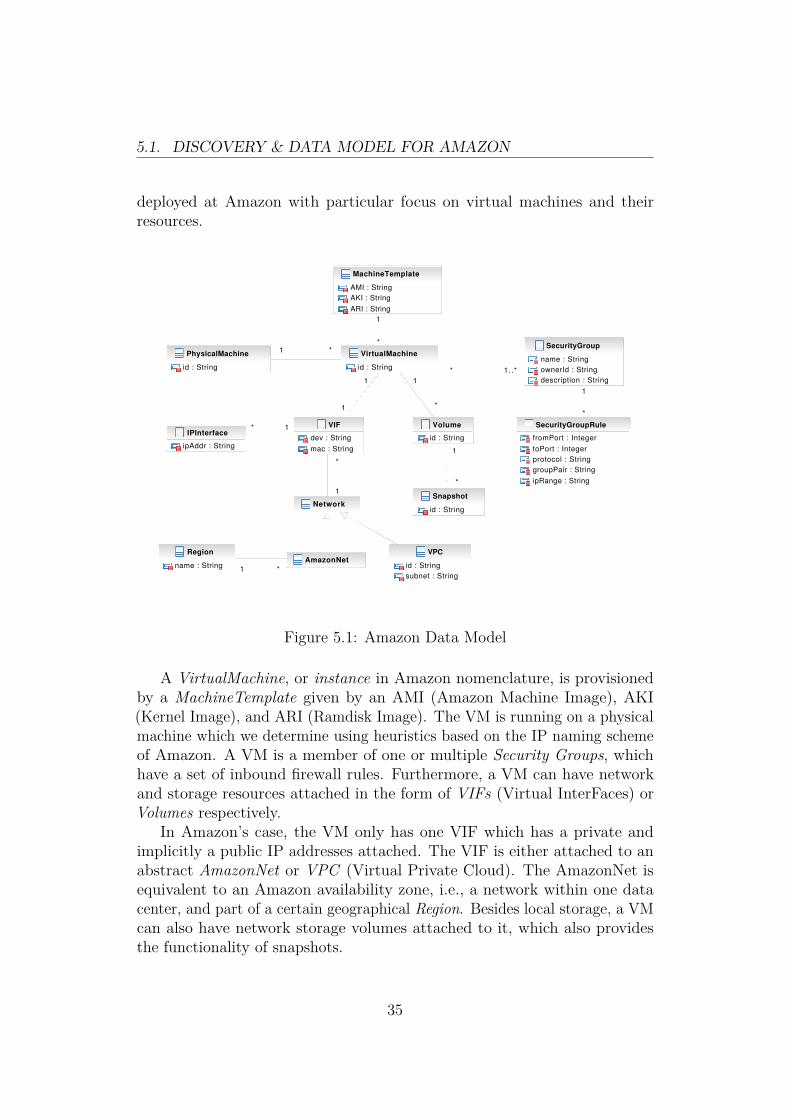
5.1. DISCOVERY & DATA MODEL FOR AMAZON
deployed at Amazon with particular focus on virtual machines and theirresources.
VirtualMachine
id : String
SecurityGroup
name : String
ownerId : String
description : String
SecurityGroupRule
fromPort : Integer
toPort : Integer
protocol : String
groupPair : String
ipRange : String
PhysicalMachine
id : String
MachineTemplate
AMI : String
AKI : String
ARI : String
Volume
id : String
VIF
dev : String
mac : String
IPInterface
ipAddr : String
Network
AmazonNetRegion
name : String
VPC
id : String
subnet : String
Snapshot
id : String
*1
* 1..*
1
*
1
1
*
1
*
1
*
1
1*
1
*
1 *
Figure 5.1: Amazon Data Model
A VirtualMachine, or instance in Amazon nomenclature, is provisionedby a MachineTemplate given by an AMI (Amazon Machine Image), AKI(Kernel Image), and ARI (Ramdisk Image). The VM is running on a physicalmachine which we determine using heuristics based on the IP naming schemeof Amazon. A VM is a member of one or multiple Security Groups, whichhave a set of inbound firewall rules. Furthermore, a VM can have networkand storage resources attached in the form of VIFs (Virtual InterFaces) orVolumes respectively.
In Amazon’s case, the VM only has one VIF which has a private andimplicitly a public IP addresses attached. The VIF is either attached to anabstract AmazonNet or VPC (Virtual Private Cloud). The AmazonNet isequivalent to an Amazon availability zone, i.e., a network within one datacenter, and part of a certain geographical Region. Besides local storage, a VMcan also have network storage volumes attached to it, which also providesthe functionality of snapshots.
35

5.2. INTEGRATED MODEL & DISCOVERY FOR INFRASTRUCTURECLOUDS
5.2 Integrated Model & Discovery for Infras-tructure Clouds
The isolated data model for Amazon configurations has to be integrated intothe generic data model used within the SAVE project, in order that theSAVE prototype can handle both public and private clouds using the sameunderlying data model. In this section we will briefly discuss the integrationof the models and discovery implementation.
5.2.1 Data ModelThe Amazon data model illustrated in Figure 5.1 was integrated into theexisting SAVE realization model. The integrated model is presented inAppendix B.3. Since Amazon is based on Xen, we extended the Xen virtualmachine host and virtual machine classes for the Amazon case. The rulesof Amazon Security Groups are integrated into the generic filtering rulespart of the networking part of the model, and a VM is a member of oneor more Security Groups. We consider an AmazonNet as a network switch,i.e., all VMs are connected on the same AmazonNet switch for a specificavailability zone. At the current state of the model, the VPC functionalityhas not be integrated yet, because we do not consider hybrid clouds yet. Sincethe data model already contained a class for machine templates used for theprovisioning of VMs, the Amazon Machine Template just extends this classwith further attributes. Volumes in Amazon can either be local disks, i.e.,instance storage, or remote disks, i.e., EBS volumes.
5.2.2 DiscoveryThe discovery probe for Amazon Web Services is implemented using theAmazon EC2 Java library (for API version 2009-11-30 [Ama10c]) in less than170 lines of Java code. The translation from the discovery data in XML intothe integrated realization model is also implemented in Java in around 330lines of code, which contains all the Amazon specific part related to mappingdiscovery data to classes in the data model.
36

Chapter 6
Multi-tier VirtualInfrastructures in PublicClouds
For hosting enterprise-grade applications and infrastructures, it is importantthat common security architectures can be established in the public cloud. Onecommon security architecture is to split complex applications into multipletiers that correspond to security zones, such as Internet, demilitarized zone(DMZ), and intranet.
This chapter shows how multi-tier security architectures can be imple-mented in a public cloud. Using Amazon EC2, we focus on how the securityof such multi-tier architectures can be assessed. In the first part of thischapter we will present our approach that discovers the actual configurationof such architectures and then validates it against a desired configuration.Furthermore we assess the vulnerability of such a configuration using attackgraphs and recommending potential improvements.
In the second part we compare two methods of deploying multi-tier virtualinfrastructures on Amazon EC2 and outline the offered isolation levels for bothmethods. In the final part, we propose a method for detecting and evaluatingconfiguration changes in multi-tier virtual infrastructure deployments. Thismethod can be used to track the security levels of such architectures andindicate degradations of the security.
37

6.1. CONFIGURATION SECURITY AUDITS
6.1 Configuration Security Audits
6.1.1 IntroductionToday, public clouds such as Amazon EC2 are used to host multi-tier infras-tructures. Such infrastructures, e.g., comprise interconnected web, application,and database servers that may then be synchronized with databases in the en-terprise. While this approach provides scalability, it exposes private personalor critical company data to attacks.
In order to mitigate this risk, security concepts similar to today’s well-known security zones have been introduced. The so-called security groupsof Amazon allow users to group machines while restricting communicationthrough firewall-like rules. Nevertheless, the resulting configurations canbe complex and thus error prone. According to [Woo04], more than half of37 analyzed corporate firewall configurations contained 9 out of 12 possiblemistakes or problems, therefore we can assume a similar number defects whenusing firewall-like concepts in the cloud.
In this section, we propose a novel approach towards assessing the actualsecurity of such multi-tier set-ups and the corresponding security policies. Wefocus on Amazon’s EC2 as one example of a public cloud. We first show howthe correct configuration of Amazon’s security groups can be visualized andvalidated. We then proceed by assessing the resulting threats using attack-graphs that show the risk of attacks for a given multi-tier set-up. Finally, weshow how a given multi-tier set-up can be automatically transformed suchthat the functionality remains while the complexity and vulnerabilities arereduced.
Scenario
Throughout this section we will use the same scenario to illustrate the differentaudit and analysis methods. We consider an example configuration of a multi-tier web application widely used in real-world deployments consisting of web,application, and database servers. The web servers are reachable on the twocommon web server ports 80 (http) and 443 (https) over TCP from any source.The application servers are only reachable on an application specific port,e.g., 8080 TCP, from the web servers. Furthermore, the database serversare only reachable from the application servers on port 3306 (mysql) TCP.For maintenance purposes, all servers allow ssh access (22 TCP) from thecorporate network, e.g., 1.2.3.4/24, and the servers accept ICMP packets fromany source.
38

6.1. CONFIGURATION SECURITY AUDITS
6.1.2 Reachability AuditIn this subsection we will discuss the audit of security group configurationswith regard to reachability, i.e., analyzing the information flow allowed bythe configuration. Visualization of the allowed information flow and a reacha-bility query language are presented which can support the administrator indeveloping new configurations and in discovering potential mistakes in thecurrent configuration. A policy language and automated analysis are shownfor the periodic verification of the configuration correctness.
The current configuration of the security groups and related information,e.g., the security group membership of VMs, are obtained in the configurationdiscovery phase described in Section 5.1.
Reachability Graph
The visualization and the later proposed automated analysis is based on adirected multi-graph constructed from the configuration information obtainedthrough the Amazon API. The vertices of the graph represent the set ofsources and security groups defined in the configuration. The edges denotethe allowed information flow specified in the rules of a security group betweenthe sources and that particular group. For example, security group web allowsthe Internet, i.e., 0.0.0.0/0, to access on port 80 TCP. The graph wouldconsist of two vertices for the security group and Internet source IP with andirected edge between them labeled 80/tcp.
Visualization
Visualizing the reachability graph is useful for manual inspection of thecorrectness of the current security group configuration. According to [Goo07],visualization takes advantage of vision, the highest bandwidth input device,and of the human perceptual abilities to make anomalies obvious to the user.
Listing 6.1 shows the output of the ec2-describe-group command, whichdisplays the current security group configuration and is part of the command-line management suite of Amazon EC2. Even in such a simple example, it isdifficult to assess the correctness of the given configuration. Amazon allowsup to 100 defined security groups with multiple filter rules per group, whichwould result in a highly complex configuration that is even more difficult toevaluate.
In contrast Figure 6.1 illustrates the visualization of the reachability graphof the same configuration. In our opinion, the visualization can be moreintuitively understood and judged for correctness. The multi-tier structure of
39

6.1. CONFIGURATION SECURITY AUDITS
GROUP 1234 app a p p l i c a t i o n s e r v e rPERMISSION 1234 app ALLOWS tcp 8080 8080 FROM USER 1234←↩
GRPNAME web
GROUP 1234 db database s e r v e rPERMISSION 1234 db ALLOWS tcp 3306 3306 FROM USER 1234←↩
GRPNAME app
GROUP 1234 web web s e r v e rPERMISSION 1234 web ALLOWS tcp 80 80 FROM CIDR 0 . 0 . 0 . 0 / 0PERMISSION 1234 web ALLOWS tcp 443 443 FROM CIDR 0 . 0 . 0 . 0 / 0
GROUP 1234 d e f a u l t d e f a u l t groupPERMISSION 1234 d e f a u l t ALLOWS tcp 22 22 FROM CIDR ←↩
1 . 2 . 3 . 4 / 2 4PERMISSION 1234 d e f a u l t ALLOWS icmp −1 −1 FROM CIDR ←↩
0 . 0 . 0 . 0 / 0
Listing 6.1: ec2-describe-group Command Output
the security groups is immediately obvious to the auditor and the externalsources, i.e., IP ranges, are clearly pointed out.
Potential misconfigurations can easily be spotted in the visualization. Forexample, if the database security group would allow any source to access thedatabase, rather than just the application group, it can easily be detectedduring the inspection due to an edge between the vertices 0.0.0.0/0 and db.
Query & Policy Language
The visualization of the security group reachability is only useful for a man-ual inspection of the correctness of an initial security groups configuration.Afterwards, a periodic verification of the configuration against a policy spec-ification is desired, in order to retain the correctness of the configuration,because changes in the configuration over its lifetime might cause violationswith regard to its original intentions. Furthermore, queries can be used toanswer questions about the reachability of the current configuration, e.g., forresolving reachability problems.
Query Language: Reachability queries are specified in the following form:from s to d port p proto p′. s is either an IP address (specified as asingle address or IP range), a security group, or any for matching all sources.d is either a security group or any. p can be one specific port or a port rangep1 − p2. Both are transformed to a tuple (p1, p2), where in the former case
40

6.1. CONFIGURATION SECURITY AUDITS
0.0.0.0/0
web
app
db
1.2.3.4/24
default
80/tcp 443/tcp
8080/tcp
3306/tcp
22/tcp-1/icmp
Figure 6.1: Visualization of Security Groups Reachability
p1 = p2. Valid values for p′ are tcp, udp, icmp. p and p′ can be set to any incase one is not interested in the specific port or protocol.
Policy Language: For the policy language we will consider two cases. Anever policy specifies a reachability which should never be established betweena source and destination. An only policy allows only a specific reachability,i.e., the given information flow is allowed but any other flow is considered aviolation of the policy. never policies are specified similarly to queries: neverfrom s to d port p proto p′.
For an only policy we have to extend this syntax slightly to allow the spec-ification of multiple port and protocol pairs per source and destination: onlyfrom s to d port p1 proto p′1 and . . . and port pn proto p′n. Consideras an example a web server group which should only be reachable to port80/tcp and port 443/tcp: only from 0.0.0.0/0 to web port 80 prototcp and port 443 proto tcp.
Reachability Analysis & Policy Verification
The processing and verification of the reachability queries and policies isrealized using two algorithms which are explained in the following.
Reachability Analysis: The algorithm to process the reachability queriesis given in Algorithm 1. We consider a sample input query: from s to d
41

6.1. CONFIGURATION SECURITY AUDITS
port p1− p2 proto p′, where the values (s, d, (p1, p2), p′) are passed as inputparameters to the algorithm. The algorithm returns True if the reachabilityspecified in the query is established for a given reachability graph GR = (V,E).
Algorithm 1: Process a Reachability QueryInput: Reachability Graph GR, Query (s, d, (p1, p2), p′)Output: True or False if query matches GR
E ′ ← ∅foreach e ∈ E do
if (s = any or s ⊆ e.source) and (d = any or d = e.destination)then
E ′ ← E ′ ∪ {e}foreach e ∈ E ′ do
c← e.constraintif (p′ = any or p′ = c.proto) and (p1 = any or (c.p1 ≤ p1 andp2 ≤ c.p2)) then
return Truereturn False
In the first step, we construct a set of edges E ′ containing all edges betweenthe given source and destination vertices. Since a source can be specified asan IP range, we have to check if the given source s is a subset of the sourceof the edge, e.g., 10.0.0.0/24 ⊂ 0.0.0.0/0. In case the source of the edge ands are security groups, ⊆ acts as an ordinary equality operator. Otherwise,when either the source or destination is specified as any, we will include theedge regardless of the source or destination respectively.
In the second step, we compare the constraints of the edges in E ′ (indicatedby e.constraint) with the constraints specified in the query. any for the portsand protocol short circuits the check, i.e., the query is only interested in anedge between s and d. In the other case, the protocols must be equal and theport range in the query enclosed in the port range of the edge constraint.
Policy Verification: The process of the verification of reachability policiesleverages the previously described query processing algorithm. For neverpolicies in the form never from s to d port p1 − p2 proto p′, we simplyconvert them to a query (s, d, (p1, p2), p′) which has to evaluate to False.Otherwise the given policy is not satisfied.
In case of an only policy like only from s to d port p1,1 − p1,2 protop′1 and . . . and port pn,1−pn,2 proto p′n, we have to do a two step processfor the verification. First we convert the policy into n queries of the form
42

6.1. CONFIGURATION SECURITY AUDITS
(s, d, (pi,1, pi,2), p′i) which all have to evaluate to True. Otherwise the reacha-bility specified in the policy is not satisfied. Furthermore, we have to verifythat other information flows are not possible in the reachability graph for theparticular source and destination, i.e., queries of the complement (s, d, p̄, p̄′)have to evaluate to False. This exclusiveness of the reachability specified inthe only policy is checked with Algorithm 2.
Algorithm 2: Verify Exclusiveness of an only PolicyInput: Reachability Graph GR, Policy
(s, d, [((p1,1, p1,2), p′1), . . . , ((pn,1, pn,2), p′n)])Output: True or False if the policy is satisfied[Construction of E ′ equal to Algorithm 1]foreach e ∈ E ′ do
B ← [True, True, . . .]c← e.constraintfor i = 1 to n do
if (p′i 6= any and p′i 6= c.proto) or (pi,1 6= any and (c.p1 < pi,1or pi,2 < c.p2)) then
Bi ← False
if True /∈ B thenreturn False
return True
The construction of the set of relevant edges E ′ is equal to the part inAlgorithm 1. For each edge in this set, we initialize an array B, with a sizeequal to the number of port-protocol pairs specified in the policy, with Truevalues. For each such pair, we check the edge constraint if it allows furtherinformation flow than already allowed by the pair. For example the policyrequires only port (p1, p2) but the edge constraint allows (p1 − 1, p2 + 1),therefore allows further information flow with two more ports and therebyviolates the only policy.
If the policy specifies any for the port or protocol then we can skip theconstraint check. Otherwise, if the protocols of the policy and edge constraintare different, or the port range of the edge constraint is larger than the onespecified in the policy, we mark a violation in the array B by setting the arrayslot corresponding to the port-protocol pair to False. After checking all pairsfor a particular edge constraint, we test if B does not contain any True value.If this is the case, then the policy is violated, because none port-protocol pairmatched the edge constraint. In case of a non-violation, at least one pairwould have matched and resulted in a True value in B.
43

6.1. CONFIGURATION SECURITY AUDITS
The periodic verification uses a policy specification consisting of a set ofpolicies, which all have to evaluate to True, in order that the verification issuccessful and the configuration does not contain any violations.
6.1.3 Audit using Attack GraphsWhile the technique presented in the previous subsection targeted singleedges, we now extend this approach to inspect the whole graph. Since purereachability is a rather weak security measure, we extend the edges with aweight of how likely it is that they will be vulnerable to an attack. This resultsin a kind of attack graph [TASB07, WLI07, WLI08]. The audit of securityconfigurations using these attack graphs is concerned about the impact ofsecurity group rules with regard to services security, and is based on thepreviously presented reachability analysis.
Attack Graph
An attack graph for security groups consists of vertices based on IP rangesand AMIs (Amazon Machine Images), where the information flow between thevertices is given by the rules of the security groups the VMs — provisionedfrom the AMIs — are members of. Furthermore, the edges are labeled with aseverity rating for the service running in the AMI and allowed by a securitygroup rule.
For example, assume that VM 1 is a member of security group web andprovisioned from AMI 1. There exists a rule in web that allows 0.0.0.0/0to access on port 443/tcp. Suppose the web server running in AMI 1 hasa known vulnerability, then there would be an edge between 0.0.0.0/0 andAMI 1 in the attack graph with a label 443/tcp medium.
Graph Construction
The previously described attack graph can be automatically constructed inthree steps.
The first step is to establish the relationship between AMIs and securitygroups. Using the Amazon API, we can obtain the currently running VMs,including information on the AMIs used for provisioning them and the securitygroups they are members of. Typically, the number of different AMIs persecurity group should be rather small, because the role of the security groupis reflected by a specific AMI, e.g., multiple instances of a web server AMIwould be member of the web security group. In our example we assume theexistence of four different AMIs; AMI 1 is a member of security group web,
44

6.1. CONFIGURATION SECURITY AUDITS
AMI 2 of app, AMI 3 and AMI 4 of db. Furthermore, all AMIs are memberof default. Figure 6.2 illustrates the relationships between security groupsand AMIs for our scenario.
0.0.0.0/0
web AMI 1
app AMI 2
db AMI 3
AMI 4
default
1.2.3.4/24
80/tcp 443/tcp
8080/tcp
3306/tcp
22/tcp-1/icmp
Figure 6.2: Relationship between Security Groups and AMIs
The second step in the construction is to obtain a severity rating forthe services running in the AMIs. Using Amazon EC2 we can start eachAMI in a separate VM for analysis purposes, thereby not affecting theproduction systems. The AMI’s security from an external point of view canbe determined in the VM using vulnerability scanners like Nessus [Ten10].Further information such as patch levels and version numbers can be obtainedfrom an internal point of view by logging into the AMI instance. For each portof an AMI we thus obtain a severity rating from a domain of vulnerabilityratings. Here we use the range of Low, Medium, or High. For typicalapplications this level of granularity seems to be sufficient, but a morefine-grained rating can be achieved using Common Vulnerability ScoringSystem (CVSS) [MSR07].
The final step in the construction is to combine the previously obtainedinformation with the reachability graph of security groups. A security groupis replaced by all the AMIs related to that particular group, and the edges
45

6.1. CONFIGURATION SECURITY AUDITS
AMI 10.0.0.0/0 0.0.0.0/0
AMI 2 AMI 3AMI 4
1.2.3.4/24 0.0.0.0/0
80/tcplow
443/tcpmedium
8080/tcpmedium
3306/tcplow
3306/tcpmedium
22/tcplow
22/tcp
high
22/tcp
low
22/tcplow
-1/icmplow
-1/icmplow
-1/icmplow
-1/icmplow
Figure 6.3: Attack Graph of the Multi-Tier Application
between the sources and the AMIs are additionally labeled with the severityrating for the port and protocol associated with each edge. Figure 6.3illustrates the attack graph for the example scenario where thicker edgesrepresent higher vulnerability ratings.
In the current configuration, an attacker in the corporate network couldcompromise a VM of the application server group, which are provisionedusing AMI 2, through a vulnerability in the ssh service. Afterwards, furtherattacks can be launched against the medium rated mysql service running oninstances of AMI 4, potentially compromising the database.
Query & Policy Language
When analyzing attack graphs constructed from cloud configurations, one isparticularly interested in the weakest path from one vertex to another. Theweakest path is the shortest path with the highest vulnerability rating, i.e.,the most likely path an attacker would take to compromise a specific resource,because less vulnerabilities with high severity ratings are more likely to beexploited successfully.
Query Language: Reachability queries are specified in the following form:from s to d vuln v. We drop protocols and ports in the query, since we
46

6.1. CONFIGURATION SECURITY AUDITS
are mostly interested in the vulnerability, not how an attack is performed. sis either an IP address (specified as a single address or IP range), an AMI, orany for matching all sources, and d is either an AMI or any. The vulnerabilityvalue v can be any value from the domain of vulnerability ratings, or thespecial value any. The result of such a query is a set of shortest paths P froms to d. If any is specified for v, then all paths are considered, otherwise onlypaths with a minimum vulnerability higher than or equal to v are considered.
Policy Language: For the policy language we consider the same cases as inSubsection 6.1.2. As before, a never policy specifies an unwanted connectionbetween a source and a destination. They are specified similarly to queries:never from s to d vuln v, where s, d, and v can have the same values asfor queries. The interpretation of a never policy is that there may never be aconnection with a vulnerability rating higher than or equal to v.
Unlike before, only policies are very similar to never policies when dealingwith attack graphs. This is because we only want to restrict the vulnerabilityratings allowed on connections between nodes. These policies have the formonly from s to d vuln v, that is the only difference is the initial keyword.Again, s, d, and v can have the same values as for queries. The interpretationof an only policy is that there may only be connections with vulnerabilityratings lower than or equal to v.
Weakest Path Algorithm & Policy Verification
The analysis of queries on the attack graph, and the testing of attack graphsagainst policies, is performed by means of Dijkstra’s shortest path algorithmon a weighted graph. The weight of the edges is based on the vulnerabilityrating where the weight relation is the following: High < Medium < Low.Since Dijkstra’s algorithm will determine the shortest path with the lowestweight, we will obtain the most likely path an attacker would take. Incase the query or policy contains a vulnerability parameter unequal to any,annotated by any, we have to transform the attack graph before performingthe Dijkstra’s algorithm by removing all edges with a vulnerability ratinglower than the one specified.
Based on the four different combinations of query/policy source and des-tination parameters, i.e., (any, any), (any, any), (any, any), and (any, any),we have to perform a different variation of the Dijkstra’s algorithm. For thecase (any, any), i.e., a specific source and destination, the Dijkstra’s algorithmcan be terminated upon finding the shortest path for the destination. Inthe other case where the destination is any, the regular algorithm will beperformed which determines the shortest path between a single source and all
47

6.1. CONFIGURATION SECURITY AUDITS
other vertices. For (any, any), i.e., the source is any, we reverse the attackgraph and start the single source Dijkstra’s algorithm from the destination.Due to the reversal of the attack graph, we also have to reverse the pathsobtained by the Dijkstra’s algorithm. In case of (any, any), all-pairs shortestpaths is determined using Dijkstra’s algorithm starting from every vertex.Alternatively, the Floyd-Warshall algorithm could be used to determine theall-pairs shortest paths.
The policy processing can be based on the approach of finding the weakestpath. A never policy basically states the fact that no weakest path with theproperties specified in the policy should exist. In case of only policies, theystate that never should exist a path with a vulnerability higher than the onespecified. For example, the policy specifies a medium vulnerability, then nopath with a high vulnerability should exist.
6.1.4 Security Groups TransformationThe purpose of the transformation process is to reduce the complexity of theconfiguration by removing unnecessary rules and extracting common ones,and to improve the security by splitting existing security groups.
Splitting of Groups: Based on the attack graph and a specification of thedesired services dependency, we can propose a new security group configurationby splitting existing security groups. The splitting process has to balancebetween increasing configuration complexity and security. One extreme casewould be to place each AMI in a separate security group, therefore minimizingthe affect of a vulnerability in one AMI to other AMIs. Generally, high ormedium rated AMIs are isolated in separate groups, while AMIs with a lowor no severity rating can remain in the same group.
Closing Unnecessary Open Ports: Using the AMI analysis of open portsand the rules of the corresponding security group the instances of that AMIare a member of, we can identify unnecessary rules in the configuration if portsare opened in the configuration, but no service is listening on that particularport in the AMI instances. The difference of the set of ports opened by thesecurity group and the set of ports used by the AMIs represents the portswhich are unnecessarily opened. These ports can be automatically removedfrom the security group rules set during a transformation phase.
Extracting Common Ports: A VM can be a member of several securitygroups and we can leverage this fact to reduce the complexity of the con-
48

6.1. CONFIGURATION SECURITY AUDITS
figuration by identifying common ports in the rules of the existing groupsand extract them into a separate group. For example, if all groups wouldallow ssh access from a corporate network and allow ICMP packets, we couldautomatically extract these rules into a separate group. All instances would beadditionally a member of that group. The principle is similar to Refactoringfound in software engineering, where common functionality is extracted.
6.1.5 ImplementationWe implemented the previously described construction of reachability andattack graphs, as well as the processing of queries and policies for suchgraphs in Python. The implementation, called SAVEly, was straight forwardgiven the detailed algorithms presented earlier and it is given in Listing D.1in Appendix D. We are using the boto [bot10] library for obtaining theconfiguration from Amazon EC2, and the NetworkX [Net10] library for thegraph handling and shortest-path algorithms.
The attack graph construction is using the OpenVAS vulnerability scan-ner [Ope10]. For each discovered AMI we spawn a new instance in a specializedsavely_scan security group which allows all traffic from the scanner machine’sIP address, instead of scanning the production servers directly. This approachof scanning will not affect the production servers due to aggressive scanningprobes.
Practical results for the tool will be given in Chapter 7.
6.1.6 Improvements for Security GroupsIn this section we propose a set of potential improvements for security groups,in order to increase the security of deployments based on such a concept.
Outbound Filtering: An obvious limitation of the current security groupconcept is the missing functionality of filtering outbound traffic. A VM cancontact any host on the Internet which could result in a leakage of sensitiveinformation in case a VM is infected with malware. The current concept issimple and probably good enough for most current customers, but in case of awider adoption and enterprise-grade deployments, the demand for outboundfiltering will raise.
Logging: The management layer does not provide any insights in the kindof traffic which was blocked by the inbound filtering. This information canbe useful for setting up intrusion detection systems and initiate prevention of
49

6.2. COMPARISON OF DEPLOYMENT METHODS
attacks in case of traffic anomalies from a certain source. Providing securitylogging information in an accessible format could create an ecosystem of third-party security appliances, which monitor such logs and act upon maliciousevents.
AMI Membership Policies: An AMI can have services installed whichdo not have proper authentication and authorization mechanism and areintended to run in an isolated environment. An example for such a serviceis memcached, a popular network-accessible caching service used by a largenumber of websites, which should only be reachable by the web or applicationservers of a deployment. However, currently an AMI can not be accompaniedby a policy specifying the security group properties required for a secureoperation of that AMI. In case of the memcached example, the AMI wouldspecify that only other security groups, or more specifically the web or appgroups, can access the memcached service.
A similar concept was proposed in [MGHW09] in the form of networkcontracts, which are part of the concept of Virtual Machine Contracts.
6.2 Comparison of Deployment MethodsIn this section we will compare two different deployment methods for multi-tiervirtual infrastructures. We consider a scenario, where an existing enterpriseIT is extended into a public infrastructure cloud and that the cloud willhost a multi-tier application. We investigate the following two methods: asetup using security groups as used in Section 6.1 and one using AmazonVirtual Private Cloud (VPC). In particular we are interested in the securityproperties of the two deployment methods and what kind of isolation levelsthey can provide.
6.2.1 Security GroupsInstead of allowing the Internet (0.0.0.0/0) to access the first tier of the multi-tier application used in Section 6.1, we restrict this access to the enterprisenetwork. If all other tiers only allow access from another tier, then themulti-tier application is separated from the Internet and only accessible fromthe enterprise. The connection between the first tier and the enterprise mightneed to be further secured using a VPN tunnel, in case sensitive informationare transferred between the enterprise and the multi-tier virtual infrastructure.The same applies to inter-tier communication, in case the tiers are located in
50

6.2. COMPARISON OF DEPLOYMENT METHODS
different Amazon regions or availability zones and traverse the Internet, or incase that the Amazon network is not trusted.
6.2.2 Virtual Private CloudAmazon Virtual Private Cloud (VPC) was already briefly introduced inSection 2.3.2. A VPN endpoint is provided by Amazon in order to securethe network communication between the enterprise and the cloud resourcesusing a VPN tunnel. The IP addresses of VMs running within a VPC areuser-specified, therefore allows a seamless integration of cloud resources intothe enterprise network. The subnet assigned to a VPC can further dividedinto multiple subnets to host the VMs, which are arranged in a star topologywith a router in the middle. Each tier can be placed in a different subnet aspart of a VPC. At the time of this writing, only one VPC per customer isallowed.
6.2.3 Isolation LevelsA VPC can be divided into multiple subnets each hosting a different tier ofa multi-tier deployment, but the communication between the tiers can notbe restricted in any way, because customers do not have access to the routerplaced in the middle of the subnets star topology. Applying network filteringto only allow certain tiers to communicate with each other is not possible inthe current form of the VPC offering. Furthermore, security groups are alsonot available in combination with VPC, which would be useful with anotherVPC subnet as a possible source in a security group rule. The only way leftis to do filtering based on VPC subnets within the VMs, which inhibits theflexibility of the cloud and could be deactivated by an administrator of theVM or malware.
In case of a security group based setup, the inter-tier communication caneasily be configured in a flexible way, and the filtering is performed outside ofthe VM, therefore it can not be tampered by a VM administrator or malware.
A VPC shares the same underlying physical infrastructure as the restof the Amazon cloud and is not completely isolated from other customers.Therefore, intra-VPC traffic also needs to be further secured in case one doesnot trust the network in Amazon data centers.
Since a VPC is isolated in terms of networking, a misconfiguration whichwould expose an instance of a VPC to the Internet is less likely comparedto a security group setup. All external traffic of a VPC passes through theenterprise network and can be filtered and analyzed using existing security
51

6.2. COMPARISON OF DEPLOYMENT METHODS
infrastructure in the enterprise. For the security group setup, misconfigura-tions are more likely but can be mitigated using the security audit processdescribed in Section 6.1.
6.2.4 ConclusionsThe advantages of a VPC are clearly the seamless integration into an en-terprise network by using user-specified IP ranges and an Amazon providedVPN endpoint. The network isolation of a VPC leaves less possibility ofmisconfigurations, which would expose a VM of a VPC to the Internet. Incase of security groups, a misconfigured rule could potentially expose a VMto the Internet, but a security audit process could reduce the possibility ofsuch a problem.
A huge disadvantage of a VPC based deployment of a multi-tier infras-tructure is the missing functionality of restricting inter-tier communication onAmazon level. All tiers, i.e., VPC subnets, can freely communicate with eachother, if not otherwise restricted by the individual VMs, because customeraccess to the VPC router or security groups in a VPC are not available at thetime of this writing. In contrast, a security group based deployment allowsan easy configuration of inter-tier communication restrictions. An alternativeby placing each tier in a separate VPC and filter inter-VPC traffic on thecustomer VPC endpoint is also not possible, because the number of VPCsper customer is limited to one.
In case one tier requires access to external resources or provides a serviceto hosts not part of the multi-tier application or enterprise network, suchtraffic would increase the overall traffic costs in a VPC based deployment. Wehave to take into account the traffic costs between Amazon and the enterprise,and between the enterprise and the external host. In a security group baseddeployment, such traffic costs are limited to the traffic between Amazon andthe external host.
We can conclude that a security group based deployment for multi-tierinfrastructures is preferred, due to the limited functionality of VPC regardinginter-tier communication restriction and costs. However, the current VPCoffering is still in testing phase, so it might improve until a final stage isreached and might be superior to security groups. Furthermore, for a securitygroup setup, an automated audit process is recommended to mitigate theproblems of misconfigurations and accidental exposure of VMs.
52

6.3. ANALYSIS OF CONFIGURATION CHANGES
6.3 Analysis of Configuration ChangesThe configuration of virtual infrastructures deployed on public clouds can bevery agile: new machines are added or modified, firewall settings are changed,and the overall complexity increases. We are interested in automaticallymonitoring these changes with regard to different properties. For example,one could track the overall security of the virtual infrastructure, i.e., the riskof potential security breaches, by monitoring the vulnerability ratings of thedeployed services.
In this section we will propose a method for the discovery and evaluationof configuration changes in a multi-tier application deployment. The changescan be evaluated with regard to various properties and we will focus onvulnerability ratings. Another potential property is expected availability, withregard to the replication of services, which we will briefly outline.
6.3.1 Discovery of ChangesThe first step in the process of analyzing configuration changes is the discoveryof changes by comparing two sets of configurations. Consider we have aconfiguration from time t1, C1, and a configuration from time t2, C2. We nowwant to detected the changes between these two configurations.
Changes Reflected in Attack Graphs
In this section we will present the potential changes in the configurationwhich will have an impact on the security of the system. We will argue thatthese changes are reflected in the corresponding attack graphs and that attackgraphs are a suitable representation of a configuration for a given point intime. Two graphs can be compared in order to detect the security-relatedchanges. In case of an analysis with regard to vulnerability ratings, we will seethat attack graphs have all the desired properties for detecting and evaluatingchanges. Consider the following list of possible changes to a configuration:
• Security Group– Adding a new Group– Removing a Group
• AMI– Adding a new AMI to a Security Group (SG)– Removing an AMI from a SG– Migrate an AMI from one SG to another
53

6.3. ANALYSIS OF CONFIGURATION CHANGES
– Changes within the AMI, e.g., new services• Ports (SG rules)
– Open a new port for a SG– Close a port for a SG– Change the source of a rule
We will now analyze the changes in order to determine their impact on theoverall security, i.e., the risk of security breaches depending on the vulnerabilityratings.
Security Group: The impact of adding or removing a security groupdepends on the rating of the AMIs grouped in that SG and the allowedcommunication for that SG. For example, a new SG containing multiple AMIswith several high severity rated services, which are all exposed to the Internetby the SG, will have a significant negative impact on the overall securityof the virtual infrastructure. Removing such a SG will have of course anequivalent positive impact.
AMI: In case of configuration changes involving AMIs we can determinethe following impacts. The impact of adding a new AMI depends on theseverity rating of the services located in that particular AMI and the allowedcommunication by the SG the AMI is a member of. If the SG denies allcommunication to the services of the new AMI, there will be no securityimpact, because the AMI will be isolated. We have to assume that theAMI itself is not malicious and does not try to extract internal informationby sending them outwards, because outbound filtering is not available forAmazon Security Groups. If a vulnerable services is allowed by the SG,the negative impact depends on the rating and the allowed source of thecommunication. For example, a medium rated services only accessible by thecorporate internal network could have a lower impact than a low rated serviceaccessible by anyone.
Removing an AMI will have an equivalent positive impact on the securityof the overall virtual infrastructure. Migration of an AMI can be consideredas removal and adding. Changes in an AMI are mainly concerned regardingthe security of the offered services, i.e., degradation or improvement of thevulnerability ratings of the services.
Port: Finally we are considering changes in the SG rules, i.e., opening,changing, or closing ports. The impact of opening a new port depends
54

6.3. ANALYSIS OF CONFIGURATION CHANGES
again on the services offered by AMIs located in that particular SG. If noservices on the newly opened port are offered then there will be no securityimpact. Otherwise the negative impact will depend on the severity rating ofthe opened service. Removing a port will have again an equivalent positiveimpact on the security. Changing the source of a rule can result in a negativeor positive impact. If the old source is a subset of the new one, e.g., 1.2.3.4/24⊂ 0.0.0.0/0, the result is a negative impact on the overall security, becausethe group of potential attackers was increased. In the other case, a reductionof the group of potential attackers will have a positive impact.
Conclusion: A negative or positive impact of the previously describedchanges depends in most cases on the severity rating of services, which arereflected in the attack graphs. For example, in case a new AMI is added witha service exposed by its security group, a new edge and vertex will appearin the corresponding attack graph. Therefore attack graphs are suitable fordetecting changes related to vulnerability ratings.
Detecting Changes using Attack Graphs
As previously demonstrated, attack graphs can be used to represent theconfiguration of the virtual infrastructure when analyzing changes with regardto vulnerabilities. In case a change will have an impact on the overall securityof the deployed application, the change will be reflected as a new vertex oredge in the attack graph. Since all vertices are uniquely labeled and edges areuniquely identifiable, we can easily detect differences between two given attackgraphs by performing a set difference operation on the sets of vertices andedges, instead of using a costly graph isomorphism and difference technique.
Consider the attack graphs for the two configurations C1 and C2: GC1 =(VC1 , EC1) and GC2 = (VC2 , EC2). The set of new edges appearing in thesecond configuration, e.g., due to opened ports, can be determined by Enew =EC2 \ EC1 and analogously the set of deleted edges by Edel = EC1 \ EC2 .New or deleted vertices can be determined similarly: Vnew = VC2 \ VC1 andVdel = VC1 \ VC2 , but we are mainly interested in the edges as they representpossible attack paths.
6.3.2 Evaluation of ChangesWe are now presenting the method for evaluating the set of changed verticesand edges in the attack graphs, and determining the security impact ofthese changes. Unlike previous work in the field of ranking attack graphs[MBZ+06], we are not evaluating the individual attack graphs for two separate
55

6.3. ANALYSIS OF CONFIGURATION CHANGES
configurations and compare the quantified results, but rather evaluating thedifferences between two attack graphs and propose a quantified result basedon these relative changes.
We are using the scenario presented in Section 6.1 as an example todemonstrate the evaluation. The attack graph shown in Figure 6.3 actsas the representation of configuration C1. We are now considering changesin AMI 1 and security group web resulting that a medium-rated serviceon port 8080 is accessible from anywhere. The difference is illustratedin Figure 6.4 which lead to the following set of changed edges: Enew ={(0.0.0.0/0, AMI1, 8080, tcp,medium)} and Edel = ∅.
0.0.0.0/0 AMI 1
8080/tcpmedium
Figure 6.4: Configuration Change between Attack Graphs
In general we will have a set of edges added or removed between twoconfigurations in the generic form illustrated in Figure 6.5. s can either bean IP range or another AMI, a is always an AMI in our attack graphs, andthe edge is annotated with port p, protocol p′, and vulnerability rating v.
s a
p/p’v
Figure 6.5: Generic Configuration Change
We will evaluate the impact of the individual components of such a changeand then combine them to determine the impact of the overall change betweentwo configurations. The evaluation is performed on an abstract conceptuallevel, because the choice of concrete probabilities and numbers will varysignificantly between different scenarios.
Evaluate Source
In order to evaluate the impact of the source of a change, we have to classifythe source into three possible cases with different attack probabilities:
• arbitrary IP range
• known IP range (e.g. a corporate network)
56

6.3. ANALYSIS OF CONFIGURATION CHANGES
• another AMI
For the three different classes we assume three evaluation functions f(ip), g(ip),and h(ami), which return a negative impact for the given input parameter. Anintuitive relation between the output results of these functions is f > g > h,that is, the highest negative impact is given for an arbitrary IP range, becausein this case we have no information on restrictions of such an attacker andhave to assume the worst-case scenario, i.e., the most powerful attacker. Forthe other two case, an attacker must either be an insider (e.g. in the corporatenetwork) and/or has to have compromised a specific AMI in the deployedmulti-tier application.
The negative impact result of these functions can vary depending onthe input parameter. In case of f(ip), the negative impact depends on the“wideness” of the given IP range. For example, 1.2.3.4/24 would result in alower negative impact compared to 0.0.0.0/0, because the set of potentialattackers is smaller in the first case. Of course, this is a probabilistic approach,because a very determined attacker could reside in a small specified IP rangecompared to a number of regular users in a large IP range.
In order to determine the negative impact of g(ip), we require a specifi-cation of known IP ranges with a rating of their attack probabilities. Forexample, the corporate network should have a lower probability assigned thana third-party vendor network. However, overall the negative impact should besmaller compared to f , because the attack probabilities are semi-deterministicand we do not have to assume the most powerful attacker.
Finally we consider the function h(ami) which returns a negative impactfor a given AMI. Since the AMI is part of the deployed multi-tier application,an attacker has to be either an insider or one who has compromised thespecific AMI. We can either specify an attack probability for the insiderattacker case or base the attack probability on the fact how likely the AMIwill be compromised. In the latter case, the number of incoming edges andtheir vulnerability rating can be an indicator for the probability that the AMImight get compromised.
Evaluate Service Vulnerability
Determining the negative impact on the security of the system for the servicevulnerability is straight forward. A high vulnerability rating will have agreater negative impact compared to a low rating. In the current form weuse a coarse-grained rating system consisting of high, medium, and low, buta fine-grained and numerical rating system could be adopted. For example,the Common Vulnerability Scoring System (CVSS) [MSR07] could be used.
57
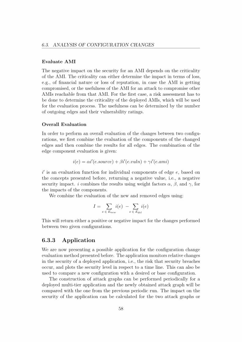
6.3. ANALYSIS OF CONFIGURATION CHANGES
Evaluate AMI
The negative impact on the security for an AMI depends on the criticalityof the AMI. The criticality can either determine the impact in terms of loss,e.g., of financial nature or loss of reputation, in case the AMI is gettingcompromised, or the usefulness of the AMI for an attack to compromise otherAMIs reachable from that AMI. For the first case, a risk assessment has tobe done to determine the criticality of the deployed AMIs, which will be usedfor the evaluation process. The usefulness can be determined by the numberof outgoing edges and their vulnerability ratings.
Overall Evaluation
In order to perform an overall evaluation of the changes between two configu-rations, we first combine the evaluation of the components of the changededges and then combine the results for all edges. The combination of theedge component evaluation is given:
i(e) = αi′(e.source) + βi′(e.vuln) + γi′(e.ami)
i′ is an evaluation function for individual components of edge e, based onthe concepts presented before, returning a negative value, i.e., a negativesecurity impact. i combines the results using weight factors α, β, and γ, forthe impacts of the components.
We combine the evaluation of the new and removed edges using:
I =∑
e ∈ Enewi(e) −
∑e ∈ Edel
i(e)
This will return either a positive or negative impact for the changes performedbetween two given configurations.
6.3.3 ApplicationWe are now presenting a possible application for the configuration changeevaluation method presented before. The application monitors relative changesin the security of a deployed application, i.e., the risk that security breachesoccur, and plots the security level in respect to a time line. This can also beused to compare a new configuration with a desired or base configuration.
The construction of attack graphs can be performed periodically for adeployed multi-tier application and the newly obtained attack graph will becompared with the one from the previous periodic run. The impact on thesecurity of the application can be calculated for the two attack graphs or
58

6.3. ANALYSIS OF CONFIGURATION CHANGES
configurations, assuming we have suitable parameters for the actual attackprobabilities, and the relative change can be plotted in a graph.
t
rel. security
basetytx
to
Figure 6.6: Security Level Monitoring
Figure 6.6 illustrates such a graph with sample values. At time to we obtainthe attack graph for the initial configuration called the base configuration.Desirably, the security of the deployed application will only improve in thefuture in relation to this base configuration. As we can see in the plot,the configuration evolves positively in comparison to the base configuration,although it also degrades locally, until time tx where configuration changeslead to a degraded security state compared to the base configuration. Anadministrator should be alarmed at this point to restore a proper configurationto obtain a security level at least as good as the one of the base configuration,which happens after time ty.
6.3.4 Beyond a Vulnerability PerspectiveAfter evaluating configuration changes with regard to vulnerability ratings ofservices, we will now give an outlook for the evaluation regarding replicationand availability.
Comparing configuration changes by the means of attack graphs is nolonger suitable for an evaluation perspective regarding replication. Importantaspects of the configuration are now:
• Dependencies of AMIs
• Number of instances of an AMI
• Replication of services
• Diversity (OS, physical location)
59

6.3. ANALYSIS OF CONFIGURATION CHANGES
These aspects of the configuration could be captured in a directed graph,where the vertices are AMIs again and the edges denote that a service isreplicated by another AMI or that a dependency between the two AMIs exist.Each vertex could have a rating assigned based on the number of instances forthat particular AMI and attributes about the operating system and physicallocation.
A high amount of dependency edges has a negative impact on the overallavailability of the deployed virtual infrastructure, because the likelihood ofcascading failures increases. Furthermore, a low number of instances for aparticular AMI has also a negative impact due to possible failures of instancesbreaking replication or dependency associations. On the other hand, a highdiversity in the infrastructure, e.g., different operating systems in differentphysical locations, has a positive impact on the availability level of theinfrastructure. Replication among the services will also have a significantpositive impact.
Similarly to the evaluation of changed edges between two attack graphs,we can apply the same approach to the analysis of changed edged betweentwo graphs of the previously described form. Additionally, the analysis ofvertices properties is required to evaluate AMI diversity and the number ofinstances.
60

Chapter 7
Evaluation & Practical Results
In this chapter we will evaluate the prototype implementation for analyzingmulti-tier application deployments on Amazon with regard to performanceand functionality. We will present practical results for analyzing an exampleapplication deployed on Amazon.
7.1 Performance EvaluationIn this section we will present the complexity of the analysis algorithms ingeneral, and discuss hypothetical and practically realistic complexities of thereachability and attack graphs. Furthermore, we will show time measurementsof using the SAVEly tool in practice.
7.1.1 Algorithm Complexity AnalysisDetermining the complexities of the algorithms presented in Section 6.1 withregard to the input graph parameters is straight-forward. For the reachabilitygraph algorithms Algorithm 1 and Algorithm 2, it is obvious that they iterateover the set of edges of the input graph. For the query algorithm we obtain acomplexity of O(|E|), and for the policy algorithm O(|E| · n) where n is thenumber of ports specified in the policy, because each edge has to be testedfor all specified ports. However, typically n � |E| which leads to O(|E|)complexity for both algorithms.
The attack graph analysis algorithms are based on variations of Dijk-stra’s algorithm for single-source and all-pairs shortest paths. According to[CSRL01], we obtain a complexity for single-source algorithm using an arrayas underlying data structure of O(|V |2 + |E|), which is in many cases domi-nated by |V |2 therefore O(|V |2). For sparse graphs, we can use a Fibonacci
61

7.1. PERFORMANCE EVALUATION
heap as the data structure and obtain a complexity of O(|E| + |V |log|V |).Using Dijkstra’s algorithm for all-pairs shortest path, we have to performthe single-source Dijkstra’s algorithm for each vertex in the graph, yieldinga complexity of O(|V |3 + |V ||E|) for the array-based variant, which is inmany cases dominated by the |V |3 therefore O(|V |3). For a sparse graph withDijkstra’s algorithm based on a Fibonacci heap starting from all vertices, weobtain O(|V |2log|V |+ |V ||E|).
7.1.2 Reachability Graph Upper Bound ComplexityIn order to evaluate the scalability of the reachability analysis algorithms, wetry to define an upper bound for the complexity a reachability graph. Weconsider a complete multi-graph of Security Groups, meaning each SG isconnected to each other SG, itself, and to all IP sources using all possibleport/protocol and ICMP combinations. Figure 7.1 illustrates such a completereachability graph, where the dotted edges represent a set of edges for allpossible port/protocol combinations.
SG1
IPnIP1 SG2 SGm
p1/p′1
pi/p′j
Figure 7.1: Security Groups Complete Graph
In order to calculate the number of edges and vertices in such a graph, anumber of parameters and assumptions are required. The following parametersare given:
• Number of Security Groups: 100
• Port Protocol Combinations: 2 · 65536
• ICMP Combinations: 256 · 14
The maximum number of Security Groups is specified by Amazon in [Ama09a].However, empirical testing showed that this limit is not enforced, but we willassume it as an upper bound which might be enforced in the future. Thenumber of port protocol combinations is given by 2 possible protocols, i.e.,
62

7.1. PERFORMANCE EVALUATION
TCP and UDP, where each protocol allows up to 65536 possible ports. Thenumber of possible ICMP combinations is given by the ICMP type field whichallows up to 256 different values (we also consider reserved values), and toeach type a number of possible codes are associated where the maximumnumber occurs for the ICMP type 3 with 14 possible values. We assume herethat the number of rules per SG is not limited, therefore allow all possiblecombinations of port/protocol rules within a SG, otherwise the number ofedges would be less than the upper bound we are defining.
The number of edges between a source (IP source or another SG) and aSG is |E ′| = 2 · 65536 + (256 · 14) resulting from all possible port/protocolcombinations. Since all IP sources and SGs are connected with all SGsusing directed edges and allow loops, we obtain a total number of edges|E| = |SG| · (|SG| + |IP |) · |E ′|. For the number of vertices we obtain|V | = |SG|+ |IP |.
In case we are assume that all possible IPv4 addresses, i.e., 232, areused as IP sources, the number of vertices and edges increases dramatically.The number of edges is in the order of 5.8e18 and the number of edgesapproximately 232. On a 1GHz computer, i.e., 1ns = 10−9s per operation, thereachability algorithms would take approximately 185 years, which is clearlynot feasible (at least on a single computer).
We will now consider more realistic scenarios to demonstrate the run-timeof the algorithms, although they do not represent the hypothetical worst-casescenario demonstrated above. If we consider |IP | = 1e3, the run-time isapproximately 15s which can be easily done. Even if we consider |IP | = 1e6,the duration increases to approximately 3.74hrs which still is realistic toachieve.
In conclusion we can say that the hypothetical worst-case scenario is notfeasible to perform on a single computer, mainly due to the number of possibleIP addresses. However, we showed that even for realistic complex scenariosthe algorithms perform in reasonable time, which follows that even very largereal-world deployment can be analyzed with the proposed algorithms in shorttime.
7.1.3 Attack Graph Upper Bound ComplexityDefining an upper bound complexity for the attack graphs in the analysis issimilar to the previous reachability graph complexity approach. Figure 7.2illustrates a complete attack graph.
Instead of considering security groups for the vertices, we are now con-sidering AMIs. The number of allowed AMIs per SG is important for thecomplexity calculation, but no official limit exists. We will assume that a
63

7.1. PERFORMANCE EVALUATION
AMI1,1
IPnIP1 AMI1,2 AMIi,j
p1/p′1/v
pi/p′j/v
Figure 7.2: Complete Attack Graph
maximum of 100 AMIs per SG is allowed, similar to the limit of the overallnumber of SGs. Therefore, |AMI| = |SG| · 100. The number of edges canthen be determined by |E| = |AMI| · (|AMI|+ |IP |) · |E ′|, which is equivalentto the number of edges in the complete reachability graph. The number ofvertices is |V | = |AMI|+ |IP |.
Since we are dealing with a complete multi-graph, the following holds:|V | � |E|, therefore the complexity of the Dijkstra’s algorithm is dominatedby |E|. Furthermore, the number of vertices and edges is even higher than inthe reachability graph example, therefore the hypothetical worst-case scenarioassuming 232 IP sources is again not feasible.
We are considering 100 AMIs per SG, therefore we can calculate thefactor with which the number of edges increases in the complete attackgraph compared to the reachability graph: d(|IP |) = 104+|IP |
1+|IP |·10−2 and therefore|E|AG = d(|IP |) · |E|RG.
For the scenario |IP | = 1e3, we are now getting a factor of 1000, thereforethe run-time is 15000s, i.e., approximately 4.1hr, which is a significantdecrease in terms of practicality of the algorithms. In order to find a practicalbut still highly complex scenario, which would act as a upper bound for real-world applications, we have to consider the edges between sources and AMIs.Currently |E ′| represents all possible combinations of port and protocol, butthis means that each AMI has a number of vulnerable services in the order of130 · 103, which is very unlikely. We now consider |E ′| = 1e3 and |IP | = 1e3,and we obtain a running time in the order of 1.8min, which is very reasonable.For |E ′| = 1e4 the run-time is still a practically reasonable 18.3min.
Due to the increased number of vertices and especially their interconnects,the complexity of the complete attack graph is much higher than comparedto a reachability graph, resulting in longer run-times of the algorithms. Thehypothetical worst-case scenario is again not feasible, but considering highlycomplex practical scenarios, which act as a lower upper bound than thehypothetical one, shows reasonable run-times.
64

7.1. PERFORMANCE EVALUATION
7.1.4 Time MeasurementsBesides discussing the algorithmic complexity and upper bounds of the graphcomplexity, we will give time measurements for the analysis on exampledeployments on Amazon using the SAVEly tool. The accuracy of the timemeasurements is not very important, because we mainly want to convey ageneral overview of the time consumptions rather than using the measurementsfor performance improvements and profiling. The measurements were obtainedon a regular laptop machine with a 2.13GHz Pentium M processor, 2 GB ofRAM, and running Gentoo Linux.
Reachability Graph Analysis
The deployed configuration results in a reachability graph with 257 vertices(resulting from the security groups) and 505 edges (based on the securitygroups rules). We obtained the following measurements for the individualparts of the analysis:
• Obtain SGs from Amazon: 1.7s
• Build reachability graph: 0.04s
• Perform reachability queries (7): 0.025s
• Perform policy check (2 never, 1 only): 0.01s
Clearly obtaining the configuration from Amazon is the slowest part in theprocess, because a cryptographically signed transaction over the Internet toAmazon’s API server has to be performed.
Attack Graph Analysis
For the construction of the attack graph we use the OpenVAS [Ope10] vulner-ability scanner with 585 plugins enabled. Furthermore, we have to obtain thesecurity groups and running instances from Amazon. We obtain the followingmeasurements with one running instance found and scanned:
• Get Security Groups: 1.6s
• Get Instances: 0.15s
• Build Attack Graph: 2min52s
65

7.2. REACHABILITY ANALYSIS RESULTS
The construction of the attack graph is by far the most time consuming partin the analysis process, because it involves starting a new instance at AmazonEC2 and performing a vulnerability scan, where the vulnerability scan is thedominating factor.
Since the constructed attack graph is rather simple, because it only involvesone AMI, we are performing the analysis on an attack graph similar to theone presented in Section 6.1 in Figure 6.3. However, the ICMP edges wereremoved. We obtain the following time measurements for performing queriesand policy checks on the attack graph:
• Queries (5): 0.01s
• Policies (1 never, 1 only): 0.0015s
Evidently for such simple attack graphs the query and policy checks can beperformed in an instant.
The most time consuming part in the attack graph analysis is the vulner-ability scan. A possible improvement for this step could be to parallelize it,i.e., start all instances at the same time and perform the vulnerability scanfrom an equal number of scanning instances. However the scanning instancescan not be run on Amazon EC2, because their policy prohibits the port scanof other instances.
7.2 Reachability Analysis ResultsWe will now present practical results from the reachability analysis. Weconsider a security group configuration for a multi-tier web application, whichwe already presented in Chapter 6.
7.2.1 Graph ConstructionFigure 7.3 illustrates the automatically constructed reachability graph usingthe security group configuration obtained from Amazon. The visualization isdone by the tool using the DOT language and graphviz [gra10].
Figure 7.4 extends the reachability graph with membership informationof AMIs, i.e., which security group contains instances of specific AMIs. Fordemonstration purposes we only consider one web server image located in thedefault and web security groups.
66

7.2. REACHABILITY ANALYSIS RESULTS
web
app
8080/tcp
default
1.2.3.4/24
22/tcp
db
3306/tcp
0.0.0.0/0
80/tcp 443/tcp -1/icmp
Figure 7.3: SAVEly Reachability Graph
web
app
8080/tcp
ami-35e60f5c
contains
default
contains
1.2.3.4/24
22/tcp
db
3306/tcp
0.0.0.0/0
80/tcp 443/tcp-1/icmp
Figure 7.4: SAVEly Security Group AMI Relationship Graph
67

7.2. REACHABILITY ANALYSIS RESULTS
7.2.2 AnalysisWe want to analyze the reachability graph of the discovered multi-tier appli-cation configuration. In the first part we get insights into the reachability byperforming queries and to verify that the desired reachability is fulfilled by thecurrent configuration. In the second part we specify undesired behavior. Thefile containing the reachability queries is given in Listing 7.1. It is naturallyderived from the specification of the multi-tier application.
from 0 . 0 . 0 . 0 / 0 to web port 80 proto tcpfrom 0 . 0 . 0 . 0 / 0 to web port 443 proto tcpfrom web to app port 8080 proto tcpfrom app to db port 3306 proto tcpfrom 0 . 0 . 0 . 0 / 0 to d e f a u l t port −1 proto icmpfrom 1 . 2 . 3 . 4 / 2 4 to d e f a u l t port 22 proto tcp
Listing 7.1: Reachability Query File
The software will check for each query if the specified reachability isfulfilled in the current configuration. The output for the previously shownquery file is given in Listing 7.2.
from 0 . 0 . 0 . 0 / 0 to web port 80 proto tcp=> Truefrom 0 . 0 . 0 . 0 / 0 to web port 443 proto tcp=> Truefrom web to app port 8080 proto tcp=> Truefrom app to db port 3306 proto tcp=> Truefrom 0 . 0 . 0 . 0 / 0 to d e f a u l t port −1 proto icmp=> Truefrom 1 . 2 . 3 . 4 / 2 4 to d e f a u l t port 22 proto tcp=> True
Listing 7.2: Reachability Query Output
In the second part we now specify the undesired reachability behavior andverify if the current configuration allows such undesired behavior. The policyfile is shown in Listing 7.3 and implements the idea that except from the webtier all other tiers should not be directly reachable from the Internet and thatthe web can only be reached on the two common web server ports.
In this case the current configuration is compliant with the policy andthe software will indicate that by printing Reachability Policy valid:True.
68

7.3. ATTACK GRAPH ANALYSIS RESULTS
never from 0 . 0 . 0 . 0 / 0 to app port any proto anynever from 0 . 0 . 0 . 0 / 0 to db port any proto anyonly from 0 . 0 . 0 . 0 / 0 to web port 80 proto tcp and port 443 proto←↩
tcp
Listing 7.3: Reachability Policy File
7.3 Attack Graph Analysis ResultsThe more interesting security analysis is based on attack graphs which wewill demonstrate in this section.
7.3.1 Graph ConstructionSince we only use one web server image for the demonstration, the resultingattack graph is very simple. The web server contained in the image has amedium rated vulnerability which can be potentially exploited by any attacker.The resulting attack graph is illustrated in Figure 7.5.
0.0.0.0/0
ami-35e60f5c
80/tcp - Medium
Figure 7.5: SAVEly Attack Graph
7.3.2 AnalysisDue to the simplicity of the resulting attack graph of the demonstrationcase, we consider the more complex attack graph shown in Chapter 6 inFigure 6.3 to demonstrate the analysis. In the first part we demonstratethe query language which supports an administrator to get an insight intothe vulnerability of services in the current configuration. The second partdeals with the policy language for specifying undesired properties of theconfiguration in terms of service vulnerabilities and attack paths.
69

7.3. ATTACK GRAPH ANALYSIS RESULTS
A sample query file for the attack graph analysis is given in Listing 7.4.The queries test the service vulnerability exposed to the Internet and thecorporate network, and the general vulnerability within the whole deployment.
from 0 . 0 . 0 . 0 / 0 to any vuln mediumfrom 0 . 0 . 0 . 0 / 0 to any vuln highfrom 1 . 2 . 3 . 4 / 2 4 to any vuln mediumfrom any to any vuln highfrom any to AMI2 vuln medium
Listing 7.4: Attack Query File
The output of the query analysis is given in Listing 7.5. For each querythe tool also provides the most likely attack paths which fulfill the query. Forexample the first query, which tests which resources could be compromised byany attackers exploiting medium rated vulnerabilities, provides us with threepotential paths resulting in the compromise of AMI1, AMI2, and AMI4.
from 0 . 0 . 0 . 0 / 0 to any vuln medium=> [ [ ’ 0 . 0 . 0 . 0 / 0 ’ , ’AMI1’ , ’AMI2’ , ’AMI4 ’ ] , [ ’ 0 . 0 . 0 . 0 / 0 ’ , ’AMI1←↩
’ ] , [ ’ 0 . 0 . 0 . 0 / 0 ’ , ’AMI1’ , ’AMI2 ’ ] ]Truefrom 0 . 0 . 0 . 0 / 0 to any vuln high=> [ ]Fa l sefrom 1 . 2 . 3 . 4 / 2 4 to any vuln medium=> [ [ ’ 1 . 2 . 3 . 4 / 2 4 ’ , ’AMI2’ , ’AMI4 ’ ] , [ ’ 1 . 2 . 3 . 4 / 2 4 ’ , ’AMI2 ’ ] , ←↩
[ ’ 0 . 0 . 0 . 0 / 0 ’ , ’AMI1’ , ’AMI2’ , ’AMI4 ’ ] , [ ’ 0 . 0 . 0 . 0 / 0 ’ , ’AMI1←↩’ ] , [ ’ 0 . 0 . 0 . 0 / 0 ’ , ’AMI1’ , ’AMI2 ’ ] ]
Truefrom any to any vuln high=> [ [ ’ 1 . 2 . 3 . 4 / 2 4 ’ , ’AMI2 ’ ] ]Truefrom any to AMI2 vuln medium=> [ [ ’ 1 . 2 . 3 . 4 / 2 4 ’ , ’AMI2 ’ ] , [ ’ 0 . 0 . 0 . 0 / 0 ’ , ’AMI1’ , ’AMI2 ’ ] , [ ’←↩
AMI1’ , ’AMI2 ’ ] ]True
Listing 7.5: Attack Query Output
Now we demonstrate the ability of the tool to verify policies, i.e., to checkfor undesired behavior. A simple policy file is shown in Listing 7.6 whichimplements the idea that an administrator wants to be sure that no highrated vulnerabilities exists in the deployed multi-tier application and that atmaximum low rated vulnerabilities are exposed to any attacker.
70

7.3. ATTACK GRAPH ANALYSIS RESULTS
never from any to any vuln highonly from 0 . 0 . 0 . 0 / 0 to any vuln low
Listing 7.6: Attack Policy File
The output of the policy analysis is given in Listing 7.7. Reconsideringthe query output previously shown, it is not surprising that both policiesare violated by the current configuration. The second last query returned apotential attack paths using a high rated vulnerability between 1.2.3.4/24and AMI2, which can be manually verified using the illustration of the attackgraph in Figure 6.3. The second policy is violated because several attackpaths for any attacker exist using medium rated vulnerabilities as shownusing the first query.
Attack Po l i cy v a l i d :p o l i c y ( ’ any ’ , ’ any ’ , ’ high ’ ) v i o l a t i o n : [ [ ’ 1 . 2 . 3 . 4 / 2 4 ’ , ’AMI2←↩
’ ] ]p o l i c y ( ’ 0 . 0 . 0 . 0 / 0 ’ , ’ any ’ , ’medium ’ ) v i o l a t i o n : ←↩
[ [ ’ 0 . 0 . 0 . 0 / 0 ’ , ’AMI1’ , ’AMI2’ , ’AMI4 ’ ] , [ ’ 0 . 0 . 0 . 0 / 0 ’ , ’←↩AMI1 ’ ] , [ ’ 0 . 0 . 0 . 0 / 0 ’ , ’AMI1’ , ’AMI2 ’ ] ]
Fa l se
Listing 7.7: Attack Policy Output
The policy violation detection with given counter-examples will be veryuseful for an administrator to fix discovered vulnerabilities in the deployedcomplex multi-tier application.
71

Chapter 8
Outlook & Open Questions
In this chapter we will give an outlook of possible future work, and we willpresent remaining open questions for future research directions.
8.1 Hybrid Cloud AnalysisThe current state of the SAVE prototype covers the discovery and analysisof private clouds, and this thesis extended the prototype for the discoveryof public clouds. In case an organization operates a private cloud and alsoleverages resources provided by a public cloud provider, the current SAVEprototype will handle these two clouds as individual entities rather thanhaving an integrated view on this hybrid cloud setup.
Future work would consist of extending the SAVE prototype in a way tohandle such hybrid clouds. Amazon Virtual Private Cloud (VPC), which wasalready discussed in Section 2.3, could be used as a specific example scenariofor an initial implementation. The basic idea is to discover VPN endpoints inthe private cloud and match them with the VPN configuration deployed onAmazon, therefore “stitching” together both clouds by the concept of a VPNtunnel.
Having this integrated view opens up further analysis possibilities, e.g.,what resources of the public cloud are used by applications in the organization’sown private cloud and how information are flowing from the private to thepublic cloud. A possible scenario would be the following one: A file server inthe private cloud of an enterprise is becoming low on storage capacity andleverages additional storage resources from a public cloud provider. Sincethe file server abstracts the usage of public cloud resources, confidential orsensitive information might be stored on this external storage resources.
72

8.2. AMAZON SECURITY GROUP TRANSFORMATION
8.2 Amazon Security Group TransformationIn Section 6.1 we presented a method to transform Amazon Security Groupconfiguration based on insights obtained in the analysis of reachability andattack graphs. We identified two approaches for future work in order toimprove and increase the accuracy of the transformation method.
Besides splitting security groups, it would also be interesting to split AMIs.In case an AMI contains multiple services with different severity ratings, thehigh severity services should be isolated from the other ones. This splittingof an AMI is more difficult to automate, since we have to understand theconfiguration of the service we want to isolate, in order to move it to aseparate AMI. The open question is how to safely extract services from anoperating system image without breaking the functionality of the service andpotential dependencies of services hosted on the same image.
Another improvement for increasing the accuracy of the transformationand automating the whole process is the automated discovery of servicedependencies. For example, if we could discovery that two AMIs communicateusing a certain protocol and port in one direction, we could place these AMIsin different security groups and only specify for one group to allow thatspecific port and protocol.
8.3 Design ToolThe current main functionality of the SAVE and SAVEly prototypes is toaudit and visualize the current configuration of virtualized environments andmulti-tier application deployments respectively. In order to further supportadministrators of such environments and deployments regarding securitydecisions, a design tool providing immediate feedback on possible changeswould be desired. For example, an administrator could move VMs/AMIs fromone security group to another and the tool would provide immediate feedbackon reachability and service vulnerability issues. In case the change does nothave any undesired side effects, it can be deployed by the administrator in aneasy way. In general we are interested in What-If analysis for changes donein virtualized environments or multi-tier application deployments.
8.4 Complex Firewall Rules AnalysisAmazon opted for a simple firewall scheme implemented in their securitygroups suitable for the majority of customers but limited in its functionality.Outbound filtering can not be achieved, changing the default firewall behavior
73

8.5. SAVELY FOR PRIVATE CLOUDS
to accept and explicitly specify deny rules is not possible, and further firewallcapabilities like stateful rules and handling protocols besides TCP, UDP, andICMP, are not implemented.
In case that Amazon will introduce more advanced firewall features tocope with enterprise demands, the complexity of the firewall rules used bysecurity groups will increase and hence requires more sophisticated analysisapproaches. A wide body of research in complex firewall rules analysis,e.g., [BMNW04, MWZ00, YMS+06, MWZ00], could be applied to this newscenario.
8.5 SAVEly for Private CloudsAnother open question is how the analysis techniques presented for theAmazon cloud can be transferred to private clouds where information aboutthe configuration are harder to extract. For example, can we use the concept ofsecurity groups also in the private cloud scenario, i.e., a set of VMs hosted ona physical server which is protected by a firewall can be in a “security group”depending on the firewall configuration. Understanding the relationshipbetween the firewall rules and VMs is crucial for extracting security groupsfrom a private cloud.
Furthermore, spawning instances of production VMs for security analysispurposes, in order that the original VM is not affected by the analysis,can be more difficult in private cloud environments where the managementinfrastructure could be less automated, not ready for programmatic use, andmore heterogeneous.
74
Chapter 9
Conclusion
In this thesis we presented a novel approach of assessing the security ofmulti-tier applications deployed in infrastructure clouds using Amazon EC2as an example case. The security assessment consists of a discovery step forobtaining the current configuration of the deployment, which is transformedinto a generic data model capable of handling heterogeneous virtual envi-ronments. Based on the obtained configuration, we are able to analyze thesystem with regard to two properties: reachability and services vulnerabilities.For both cases, a query language and processor allow administrators to getan insight into the reachability and vulnerability of the services, e.g., inorder to detect misconfigurations which expose the wrong services or to findvulnerable services. Furthermore, a policy language allows the specification ofthe desired state of the system which can be periodically verified. We discussand compare two possible methods of deploying multi-tier applications in theAmazon cloud with regard to the provided isolation levels. Finally, anotherprocess of the security assessment is presented which monitors and evaluatesconfiguration changes with regard to vulnerability impact. This allows anadministrator to track the vulnerability of the deployment over time and getalarmed in case the security decreases with regard to a base configuration.We also give an outlook how the configuration changes evaluation can beextended beyond a vulnerability perspective in order to cover different aspectslike expected availability and replication.
We implemented the security assessment in Python and evaluated itagainst a sample multi-tier application on Amazon EC2. Violations in thevulnerability policies were successfully detected, and possible attack pathswere presented to the administrator in order to enable him to secure theinvolved services. Besides that practical evaluation, we also evaluated thetheoretical complexity of the algorithms involved in the analysis process forlarge input configurations. We discussed hypothetical and realistic upper-
75

bounds for the complexity of the input configurations, in order to successfullydemonstrate the feasibility of the assessment even for large deployments.
Finally, we discussed open questions and provided an outlook of futureresearch directions. For example the presented tools could be extended toa comprehensive design tool for virtual infrastructures including the visu-alization and analysis of the current state, deploying changes made in thetool directly for the virtual infrastructure, and also provide a framework fordoing what-if analysis for trying out different configuration changes and theirimpact before they are deployed.
In conclusion, we can say that our security assessment will be a valuabletool for administrators of multi-tier applications deployed in infrastructureclouds like Amazon EC2. Troubleshooting using the query languages can bedone and the policy language allows a specification of the desired state, inorder that the deployment remains secure. The monitoring of the configurationchanges regarding vulnerability impact will allow an administrator to trackthe security of the virtual infrastructure over its lifetime, and enables him tointervene in case the security degrades below a certain threshold. Our practicaland theoretical evaluation demonstrates the feasibility of this approach evenfor large deployments.
76

Bibliography
[Aci07] Onur Aciiçmez. Yet another microarchitectural attack: exploitingi-cache. In CSAW ’07: Proceedings of the 2007 ACM workshop onComputer security architecture, pages 11–18, New York, NY, USA,2007. ACM.
[AKS07] Onur Aciiçmez, Çetin Kaya Koç, and Jean-Pierre Seifert. Onthe power of simple branch prediction analysis. In ASIACCS ’07:Proceedings of the 2nd ACM symposium on Information, computerand communications security, pages 312–320, New York, NY, USA,2007. ACM.
[Ama09a] Amazon Web Services. Amazon EC2 - Network Security Concepts.Available at http://docs.amazonwebservices.com/AWSEC2/latest/UserGuide/index.html?concepts-security.html, lastaccessed June 2010, November 2009.
[Ama09b] Amazon Web Services. Amazon Web Services: Overview of SecurityProcesses, November 2009.
[Ama10a] Amazon. The Amazon Elastic Compute Cloud (EC2). Available athttp://aws.amazon.com/ec2/, last accessed March 2010, 2010.
[Ama10b] AmazonWeb Services. Extend Your IT Infrastructure with AmazonVirtual Private Cloud, January 2010.
[Ama10c] Amazon Web Services. Java Library for Amazon EC2. Avail-able at http://developer.amazonwebservices.com/connect/entry.jspa?externalID=1674, last accessed June 2010, 2010.
[BBN+09] Mihir Bellare, Zvika Brakerski, Moni Naor, Thomas Ristenpart,Gil Segev, Hovav Shacham, and Scott Yilek. Hedged public-key encryption: How to protect against bad randomness. InASIACRYPT, pages 232–249, 2009.
77

BIBLIOGRAPHY
[BCC04] Ernie Brickell, Jan Camenisch, and Liqun Chen. Direct AnonymousAttestation. In CCS ’04: Proceedings of the 11th ACM conferenceon Computer and communications security, pages 132–145, NewYork, NY, USA, 2004. ACM.
[BCP+08] Stefan Berger, Ramón Cáceres, Dimitrios Pendarakis, Reiner Sailer,Enriquillo Valdez, Ronald Perez, Wayne Schildhauer, and DeepaSrinivasan. TVDc: Managing Security in the Trusted VirtualDatacenter. SIGOPS Oper. Syst. Rev., 42(1):40–47, 2008.
[BDF+03] Paul Barham, Boris Dragovic, Keir Fraser, Steven Hand, TimHarris, Alex Ho, Rolf Neugebauer, Ian Pratt, and Andrew Warfield.Xen and the Art of Virtualization. In SOSP ’03: Proceedings ofthe nineteenth ACM symposium on Operating systems principles,pages 164–177, New York, NY, USA, 2003. ACM.
[BMNW04] Yair Bartal, Alain Mayer, Kobbi Nissim, and Avishai Wool.Firmato: A Novel Firewall Management Toolkit. ACM Trans.Comput. Syst., 22(4):381–420, 2004.
[bot10] boto. boto - Python interface to Amazon Web Services. Availableat http://code.google.com/p/boto/, last accessed June 2010,2010.
[BP98] S. Brin and L. Page. The anatomy of a large-scale hypertextualweb search engine. In Seventh International World-Wide WebConference (WWW 1998), 1998.
[CDRS07] Serdar Cabuk, Chris I. Dalton, HariGovind Ramasamy, andMatthias Schunter. Towards Automated Provisioning of SecureVirtualized Networks. In CCS ’07: Proceedings of the 14th ACMconference on Computer and communications security, pages 235–245, New York, NY, USA, 2007. ACM.
[Cis10] Cisco. Cisco Nexus 1000V Series Switches. Available athttps://www.cisco.com/en/US/prod/collateral/switches/ps9441/ps9902/data_sheet_c78-492971.html, last accessedJune 2010, 2010.
[Clo09] Cloud Security Alliance. Security Guidance for Critical Areas ofFocus in Cloud Computing, December 2009.
[Coh10] Reuven Cohen. Announcing Enomaly ECP HighAssurance Edition for Trusted Cloud Computing.
78

BIBLIOGRAPHY
Available at http://www.elasticvapor.com/2010/04/announcing-enomaly-ecp-high-assurance.html, last accessedJune 2010, 2010.
[CSRL01] Thomas H. Cormen, Clifford Stein, Ronald L. Rivest, andCharles E. Leiserson. Introduction to Algorithms. McGraw-HillHigher Education, 2001.
[CSS+09] Mihai Christodorescu, Reiner Sailer, Douglas Lee Schales, DanieleSgandurra, and Diego Zamboni. Cloud Security Is Not (Just)Virtualization Security. In CCSW ’09: Proceedings of the 2009ACM workshop on Cloud computing security, pages 97–102, NewYork, NY, USA, 2009. ACM.
[Eng08] Paul England. Practical Techniques for Operating System Attesta-tion. In Trust ’08: Proceedings of the 1st international conferenceon Trusted Computing and Trust in Information Technologies,pages 1–13, Berlin, Heidelberg, 2008. Springer-Verlag.
[ENI09] ENISA. Cloud Computing Risk Assessment. Technical report,ENISA, 2009.
[GJP+05] John Linwood Griffin, Trent Jaeger, Ronald Perez, Reiner Sailer,Leendert Van Doorn, and Ramón Cáceres. Trusted Virtual Do-mains: Toward secure distributed services. In In Proc. of the FirstWorkshop on Hot Topics in System Dependability (Hotdep05. IEEEPress, 2005.
[Goo07] John R. Goodall. Introduction to Visualization for ComputerSecurity. In VizSEC, pages 1–17, 2007.
[Goo10] Google. Google App Engine. Available at http://code.google.com/appengine/, last accessed June 2010, 2010.
[GPC+03] Tal Garfinkel, Ben Pfaff, Jim Chow, Mendel Rosenblum, and DanBoneh. Terra: A Virtual Machine-Based Platform for TrustedComputing. SIGOPS Oper. Syst. Rev., 37(5):193–206, 2003.
[GR03] Tal Garfinkel and Mendel Rosenblum. A virtual machine introspec-tion based architecture for intrusion detection. In Proc. Networkand Distributed Systems Security Symposium, February 2003.
[GR05] Tal Garfinkel and Mendel Rosenblum. When Virtual is Harder thanReal: Security Challenges in Virtual Machine Based Computing
79

BIBLIOGRAPHY
Environments. In HOTOS’05: Proceedings of the 10th conferenceon Hot Topics in Operating Systems, pages 20–20, Berkeley, CA,USA, 2005. USENIX Association.
[gra10] graphviz. Graphviz - Graph Visualization Software. Available athttp://www.graphviz.org/, last accessed June 2010, 2010.
[Her10] Heroku. Heroku - Ruby Cloud Platform as a Service. Available athttp://heroku.com/, last accessed June 2010, 2010.
[HL10] Gernot Heiser and Ben Leslie. The OKL4 Microvisor: ConvergencePoint of Microkernels and Hypervisors. In Proceedings of the 1stAsia-Pacific Workshop on Systems, New Delhi, India, Aug 2010.
[Hoh96] Michael Hohmuth. Linux-Emulation auf einem Mikrokern. Techni-cal report, TU Dresden, 1996.
[HUL06] Gernot Heiser, Volkmar Uhlig, and Joshua LeVasseur. Are Virtual-Machine Monitors Microkernels Done Right? SIGOPS Oper. Syst.Rev., 40(1):95–99, 2006.
[HWF+05] Steven Hand, AndrewWarfield, Keir Fraser, Evangelos Kotsovinos,and Dan Magenheimer. Are Virtual Machine Monitors MicrokernelsDone Right? In HOTOS’05: Proceedings of the 10th conference onHot Topics in Operating Systems, pages 1–1, Berkeley, CA, USA,2005. USENIX Association.
[Jaq07] Andrew Jaquith. Security Metrics: Replacing Fear, Uncertainty,and Doubt. Addison-Wesley Professional, 2007.
[Jer09] Jericho Forum. Cloud Cube Model: Selecting Cloud Formationsfor Secure Collaboration, April 2009.
[JLSW09] Sushil Jajodia, Peng Liu, Vipin Swarup, and Cliff Wang. CyberSituational Awareness: Issues and Research, chapter TopologicalVulnerability Analysis, pages 139–154. Springer, 2009.
[JN07] Sushil Jajodia and Steven Noel. Algorithms, Architectures, andInformation Systems Security, chapter Topological VulnerabilityAnalysis: A Powerful New Approach for Network Attack Preven-tion, Detection, and Response. World Scientific Press, 2007.
[KEH+09] Gerwin Klein, Kevin Elphinstone, Gernot Heiser, June Andronick,David Cock, Philip Derrin, Dhammika Elkaduwe, Kai Engelhardt,
80

BIBLIOGRAPHY
Rafal Kolanski, Michael Norrish, Thomas Sewell, Harvey Tuch,and Simon Winwood. seL4: Formal Verification of an OS Kernel.In Proceedings of the 22nd ACM Symposium on Operating SystemsPrinciples, pages 207–220, Big Sky, MT, USA, Oct 2009. ACM.
[KL09a] Amir R. Khakpour and Alex Liu. Quarnet: A Tool for QuantifyingStatic Network Reachability. Technical Report MSU-CSE-09-2,Department of Computer Science, Michigan State University, EastLansing, Michigan, January 2009.
[KL09b] Amir R. Khakpour and Alex X. Liu. Quantifying and Verify-ing Network Reachability. Poster at 16th ACM Conference onComputer and Communications Security, 2009.
[Kra09] F. John Krautheim. Private Virtual Infrastructure for CloudComputing. In HotCloud ’09: Workshop on Hot Topics in CloudComputing. USENIX, 2009.
[KSS+09] Sunil D. Krothapalli, Xin Sun, Yu-Wei E. Sung, Suan Aik Yeo,and Sanjay G. Rao. A toolkit for automating and visualizing vlanconfiguration. In SafeConfig ’09: Proceedings of the 2nd ACMworkshop on Assurable and usable security configuration, pages63–70, New York, NY, USA, 2009. ACM.
[Kun10] Vivek Kundra. State of Public Sector Cloud Computing, May2010.
[LI05] R. P. Lippmann and K. W. Ingols. An Annotated Review of PastPapers on Attack Graphs, 2005.
[LSNH+09] Liang Lu, Rei Safavi-Naini, Markus Hagenbuchner, Willy Susilo,Jeffrey Horton, Sweah Liang Yong, and Ah Chung Tsoi. Rankingattack graphs with graph neural networks. In ISPEC ’09: Proceed-ings of the 5th International Conference on Information SecurityPractice and Experience, pages 345–359, Berlin, Heidelberg, 2009.Springer-Verlag.
[MBZ+06] Vaibhav Mehta, Constantinos Bartzis, Haifeng Zhu, Edmund M.Clarke, and Jeannette M. Wing. Ranking Attack Graphs. In RAID,pages 127–144, 2006.
[MG09a] Peter Mell and Tim Grance. Effectively and Securely Using theCloud Computing Paradigm, October 2009.
81

BIBLIOGRAPHY
[MG09b] Peter Mell and Tim Grance. The NIST Definition of Cloud Com-puting, October 2009.
[MGHW09] Jeanna Matthews, Tal Garfinkel, Christofer Hoff, and JeffWheeler. Virtual Machine Contracts for Datacenter and CloudComputing Environments. In ACDC ’09: Proceedings of the 1stworkshop on Automated control for datacenters and clouds, pages25–30, New York, NY, USA, 2009. ACM.
[Mic10] Microsoft. Windows Azure Platform. Available at http://www.microsoft.com/windowsazure/, last accessed June 2010, 2010.
[MMH08] Derek Gordon Murray, Grzegorz Milos, and Steven Hand. Improv-ing Xen Security Through Disaggregation. In VEE ’08: Proceedingsof the fourth ACM SIGPLAN/SIGOPS international conferenceon Virtual execution environments, pages 151–160, New York, NY,USA, 2008. ACM.
[MMJZ06] Wenbo Mao, Andrew Martin, Hai Jin, and Huanguo Zhang. Inno-vations for grid security from trusted computing. In FourteenthInternational Workshop on Security Protocols, LNCS. Springer-Verlag, 2006.
[MSR07] Peter Mell, Karen Scarfone, and Sasha Romanosky. A Com-plete Guide to the Common Vulnerability Scoring System Ver-sion 2.0. Available at http://www.first.org/cvss/cvss-guide.html, last accessed June 2010, June 2007.
[MWZ00] Alain Mayer, Avishai Wool, and Elisha Ziskind. Fang: A FirewallAnalysis Engine. In SP ’00: Proceedings of the 2000 IEEE Sympo-sium on Security and Privacy, page 177, Washington, DC, USA,2000. IEEE Computer Society.
[NEJ+09] Steven Noel, Matthew Elder, Sushil Jajodia, Pramod Kalapa, ScottO’Hare, and Kenneth Prole. Advances in Topological VulnerabilityAnalysis. In CATCH ’09: Proceedings of the 2009 Cybersecu-rity Applications & Technology Conference for Homeland Security,pages 124–129, Washington, DC, USA, 2009. IEEE ComputerSociety.
[Net10] NetworkX Developers. NetworkX. Available at http://networkx.lanl.gov/, last accessed June 2010, 2010.
[Ols08] David P Olshefski. Amazon EC2. IBM internal presentation, 2008.
82

BIBLIOGRAPHY
[Ope10] OpenVAS. OpenVAS, Open Vulnerability Assessment System.Available at http://www.openvas.org, last accessed May 2010,2010.
[Orm07] Tavis Ormandy. An Empirical Study into the Security Exposureof Hosts of Hostile Virtualized Environments, 2007.
[PCL07] Bryan D. Payne, Martim Carbone, and Wenke Lee. Secure andflexible monitoring of virtual machines. In Proceedings of the 23rdAnnual Computer Security Applications Conference (ACSAC 2007),December 2007.
[Per05] Colin Percival. Cache missing for fun and profit, May 2005.
[PS98] Cynthia Phillips and Laura Painton Swiler. A graph-based systemfor network-vulnerability analysis. In NSPW ’98: Proceedings ofthe 1998 workshop on New security paradigms, pages 71–79, NewYork, NY, USA, 1998. ACM.
[Qum06] Qumranet. KVM: Kernel-based Virtualization Driver, 2006.
[Rig08] RightScale. Amazon’s Elastic Block Store explained.Available at http://blog.rightscale.com/2008/08/20/amazon-ebs-explained/, last accessed June 2010, August 2008.
[RTSS09] Thomas Ristenpart, Eran Tromer, Hovav Shacham, and StefanSavage. Hey, You, Get Off of My Cloud: Exploring InformationLeakage in Third-Party Compute Clouds. In CCS ’09: Proceedingsof the 16th ACM conference on Computer and communicationssecurity, pages 199–212, New York, NY, USA, 2009. ACM.
[Rus08] Rusty Russell. virtio: Towards a De-Facto Standard For VirtualI/O Devices. SIGOPS Oper. Syst. Rev., 42(5):95–103, 2008.
[RW10] Joanna Rutkowska and Rafal Wojtczuk. Qubes OS Architecture,January 2010.
[RY10] Thomas Ristenpart and Scott Yilek. When Good Randomness GoesBad: Virtual Machine Reset Vulnerabilities and Hedging DeployedCryptography. In Proceedings of Network and Distributed SecuritySymposium – NDSS ’10, 2010.
[SGR09] Nuno Santos, Krishna P. Gummadi, and Rodrigo Rodrigues. To-wards Trusted Cloud Computing. In HotCloud ’09: Workshop onHot Topics in Cloud Computing. USENIX, 2009.
83

BIBLIOGRAPHY
[SHJ+02] Oleg Sheyner, Joshua Haines, Somesh Jha, Richard Lippmann, andJeannette M. Wing. Automated Generation and Analysis of AttackGraphs. In SP ’02: Proceedings of the 2002 IEEE Symposiumon Security and Privacy, page 273, Washington, DC, USA, 2002.IEEE Computer Society.
[SJV+05] Reiner Sailer, Trent Jaeger, Enriquillo Valdez, Ramon Caceres,Ronald Perez, Stefan Berger, John Linwood Griffin, and Leen-dert van Doorn. Building a mac-based security architecture forthe xen open-source hypervisor. In ACSAC ’05: Proceedings ofthe 21st Annual Computer Security Applications Conference, pages276–285, Washington, DC, USA, 2005. IEEE Computer Society.
[SK10] Udo Steinberg and Bernhard Kauer. NOVA: A Microhypervisor-Based Secure Virtualization Architecture. In EuroSys ’10: Proceed-ings of the 5th European conference on Computer systems, pages209–222, New York, NY, USA, 2010. ACM.
[SPEC01] L.P. Swiler, C. Phillips, D. Ellis, and S. Chakerian. Computer-attack graph generation tool. In DARPA Information SurvivabilityConference Exposition II, 2001. DISCEX ’01. Proceedings, vol-ume 2, pages 307 –321 vol.2, 2001.
[SPG97] Laura Painton Swiler, Cynthia Phillips, and Timothy Gaylor. AGraph-Based Network-Vulnerability Analysis System. In SandiaNational Laboratories, Albuquerque,New, pages 97–3010. ACMPress, 1997.
[SVJ+05] Reiner Sailer, Enriquillo Valdez, Trent Jaeger, Ronald Perez, Leen-dert Van Doorn, John Linwood Griffin, Stefan Berger, ReinerSailer, Enriquillo Valdez, Trent Jaeger, Ronald Perez, LeendertDoorn, John Linwood, and Griffin Stefan Berger. sHype: SecureHypervisor Approach to Trusted Virtualized Systems. In IBMResearch Report RC23511, 2005.
[SW04] Oleg Sheyner and Jeannette Wing. Tools for generating andanalyzing attack graphs. In IN PROCEEDINGS OF FORMALMETHODS FOR COMPONENTS AND OBJECTS, LECTURENOTES IN COMPUTER SCIENCE, pages 344–371, 2004.
[TASB07] Tung Tran, Ehab Al-Shaer, and Raouf Boutaba. PolicyVis: Fire-wall Security Policy Visualization and Inspection. In LISA’07:Proceedings of the 21st conference on Large Installation System
84

BIBLIOGRAPHY
Administration Conference, pages 1–16, Berkeley, CA, USA, 2007.USENIX Association.
[TDSB09] Sunay Tripathi, Nicolas Droux, Thirumalai Srinivasan, and KaisBelgaied. Crossbow: From Hardware Virtualized NICs to Vir-tualized Networks. In VISA ’09: Proceedings of the 1st ACMworkshop on Virtualized infrastructure systems and architectures,pages 53–62, New York, NY, USA, 2009. ACM.
[Ten10] Tenable Network Security. Nessus, the Network Vulnerability Scan-ner. Available at http://www.nessus.org, last accessed March2010, 2010.
[VMw07] VMware. Understanding Full Virtualization, Paravirtualization,and Hardware Assist, 2007.
[VMw09] VMware. VMware ESX and VMware ESXi, 2009.
[VMw10] VMware. VMware VMsafe Security Technology. Availableat http://www.vmware.com/technical-resources/security/vmsafe/security_technology.html, last accessed June 2010,2010.
[vT10] Michael von Tessin. Towards High-Assurance Multiprocessor Vir-tualisation. In Proceedings of the 6th International VerificationWorkshop, Edinburgh, UK, Jul 2010.
[WIL+08] Lingyu Wang, Tania Islam, Tao Long, Anoop Singhal, and SushilJajodia. An attack graph-based probabilistic security metric. InProceeedings of the 22nd annual IFIP WG 11.3 working confer-ence on Data and Applications Security, pages 283–296, Berlin,Heidelberg, 2008. Springer-Verlag.
[WLI07] Leevar Williams, Richard Lippmann, and Kyle Ingols. An Interac-tive Attack Graph Cascade and Reachability Display. In VizSEC,pages 221–236, 2007.
[WLI08] Leevar Williams, Richard Lippmann, and Kyle Ingols. GARNET:A Graphical Attack Graph and Reachability Network EvaluationTool. In VizSec ’08: Proceedings of the 5th international work-shop on Visualization for Computer Security, pages 44–59, Berlin,Heidelberg, 2008. Springer-Verlag.
85

BIBLIOGRAPHY
[Woj08] Rafal Wojtczuk. Adventures with a certain Xen vulnerability (inthe PVFB backend), October 2008.
[Woo04] Avishai Wool. A Quantitative Study of Firewall ConfigurationErrors. Computer, 37(6):62–67, 2004.
[WSG+09] Timothy Wood, Prashant Shenoy, Alexandre Gerber, K.K. Ra-makrishnan, and Jacobus Van der Merwe. The Case for Enterprise-Ready Virtual Private Clouds. In HotCloud ’09: Workshop on HotTopics in Cloud Computing. USENIX, 2009.
[WSJ07a] Lingyu Wang, Anoop Singhal, and Sushil Jajodia. Measuring theOverall Security of Network Configurations Using Attack Graphs.In Proceedings of the 21st annual IFIP WG 11.3 working conferenceon Data and applications security, pages 98–112, Berlin, Heidelberg,2007. Springer-Verlag.
[WSJ07b] Lingyu Wang, Anoop Singhal, and Sushil Jajodia. Toward Measur-ing Network Security Using Attack Graphs. In QoP ’07: Proceed-ings of the 2007 ACM workshop on Quality of protection, pages49–54, New York, NY, USA, 2007. ACM.
[Xen10] XenAccess. XenAccess Library. Available at http://code.google.com/p/xenaccess/, last accessed June 2010, 2010.
[XZM+04] Geoffrey G. Xie, Jibin Zhan, David A. Maltz, Hui Zhang, AlbertGreenberg, Gisli Hjalmtysson, and Jennifer Rexford. On StaticReachability Analysis of IP Networks, 2004.
[YMS+06] Lihua Yuan, Jianning Mai, Zhendong Su, Hao Chen, Chen-NeeChuah, and Prasant Mohapatra. FIREMAN: A Toolkit for FIRE-wall Modeling and ANalysis. In SP ’06: Proceedings of the 2006IEEE Symposium on Security and Privacy, pages 199–213, Wash-ington, DC, USA, 2006. IEEE Computer Society.
86

Appendix A
Amazon EC2 ArchitectureDetails
In this appendix chapter we will provide more details about the underlyingarchitecture of Amazon EC2. The information in this chapter were gatheredfrom XenStore, which holds configuration information about all domains.A domain can read its own configuration information from XenStore usingxenstore-ls, which is part of the xen utils package. The actual XenStoredump is presented in Listing A.1.
A.1 Storage
A.1.1 Instance StorageInstance Storage appears as 3 partitions to the VM: sda1 for root, sda2for extra storage space (/mnt), and sda3 for swap. Typically the backendof these virtual block devices are based on loopback devices and/or LVMlogical volumes. Logical volumes are considered to have a better performanceand reliability compared to loopback devices. Surprisingly, sda1 is using aloopback backend as noted as node = “/dev/loop13” in the XenStore VBDentry. The actual file used by the loopback device is params = “/mnt/in-stance_image_store_3/262768”. The suffix “_3” of the directory is probablybased on the local domain number. The numerical filename of the image isrelated to the AMI ID, but the external AMI is in fact encoded.
The swap device is a LVM logical volume denoted as params = “/dev/Vol-GroupDomU/instance_swap_store_3” in XenStore. The extra storage space/mnt is also using a logical volume backend: params = “/dev/mapper/cow-VolGroupDomU-instance_ephemeral_store_3”. As indicated by cow, this
87

A.2. NETWORKING
volume is using copy-on-write functionality.
A.1.2 Elastic Block StorageThe characteristics of the Elastic Block Store (EBS) lead to the conclusionthat it is a SAN-based setup, i.e., based on iSCSI volumes. In fact it is basedon Global Network Block Device (GNBD) as indicated by the backend deviceof a EBS: params = “/dev/gnbd89”.
A.2 NetworkingAmazon uses a routed Xen network setup with DHCP providing private IPaddresses to the VMs, which can be derived from the network script name:script = “/etc/xen/scripts/ec2-vif-route-dhcpd” in XenStore. A traceroutewill show the private IP address of the router in Dom0, as well as the externalIP address of Dom0.
A.3 Domain NamingVia XenStore one can also determine the name of a VM, which is in thisexample domain = “dom_32504936”. Assuming this suffix number of thename is incremental and unique throughout the lifetime of EC2, one coulddeduce usage numbers from the domain names.
A.4 XenStore Dump
vm = "/vm/00000000−0000−0000−0000−0 ec232504936 "dev i c e = " "
v i f = " "0 = " "
backend−id = "0 "mac = " 1 2 : 3 1 : 3 9 : 0B: 2 5 : 7 7 "handle = "0 "s t a t e = "4 "backend = "/ l o c a l /domain/0/ backend/ v i f /151/0"tx−r ing−r e f = "768"rx−r ing−r e f = "769"event−channel = "6 "request−rx−copy = "0 "f ea ture−rx−n o t i f y = "1 "f ea ture−sg = "1 "
88

A.4. XENSTORE DUMP
f ea ture−gso−tcpv4 = "1 "vbd = " "
2049 = " "backend−id = "0 "v i r t u a l−dev i c e = "2049"device−type = " d i sk "s t a t e = "4 "backend = "/ l o c a l /domain/0/ backend/vbd /151/2049"r ing−r e f = "770"event−channel = "7 "p ro to co l = " x86_32−abi "
2050 = " "backend−id = "0 "v i r t u a l−dev i c e = "2050"device−type = " d i sk "s t a t e = "4 "backend = "/ l o c a l /domain/0/ backend/vbd /151/2050"r ing−r e f = "771"event−channel = "8 "p ro to co l = " x86_32−abi "
2051 = " "backend−id = "0 "v i r t u a l−dev i c e = "2051"device−type = " d i sk "s t a t e = "4 "backend = "/ l o c a l /domain/0/ backend/vbd /151/2051"r ing−r e f = "772"event−channel = "9 "p ro to co l = " x86_32−abi "
c o n t r o l = " "e r r o r = " "device−misc = " "
v i f = " "nextDeviceID = "1 "
conso l e = " "r ing−r e f = "2365586"port = "2 "l i m i t = "1048576"t ty = "/ dev/ pts /4"
name = " dom_32504936 "domid = "151"cpu = " "
0 = " "a v a i l a b i l i t y = " o n l i n e "
memory = " "t a r g e t = "1740800"
s t o r e = " "r ing−r e f = "2365587"port = "1 "
89

A.4. XENSTORE DUMP
VBD:
domain = " dom_32504936 "f rontend = "/ l o c a l /domain/151/ dev i ce /vbd /2050"dev = " sda2 "s t a t e = "4 "params = "/ dev/mapper/cow−VolGroupDomU−←↩
instance_ephemeral_store_3 "mode = "w"o n l i n e = "1 "frontend−id = "151"type = " phy "phys i ca l−dev i c e = " fd : 2 c "hotplug−s t a tu s = " connected "s e c t o r s = "312705024"i n f o = "0 "s ec to r−s i z e = "512"
domain = " dom_32504936 "f rontend = "/ l o c a l /domain/151/ dev i ce /vbd /2051"dev = " sda3 "s t a t e = "4 "params = "/ dev/VolGroupDomU/ instance_swap_store_3 "mode = "w"o n l i n e = "1 "frontend−id = "151"type = " phy "phys i ca l−dev i c e = " fd : 1 0 "hotplug−s t a tu s = " connected "s e c t o r s = "1835008"i n f o = "0 "s ec to r−s i z e = "512"
domain = " dom_32504936 "f rontend = "/ l o c a l /domain/151/ dev i ce /vbd /2049"dev = " sda1 "s t a t e = "4 "params = "/mnt/ instance_image_store_3 /262768"mode = "w"o n l i n e = "1 "frontend−id = "151"type = " f i l e "node = "/ dev/ loop13 "phys i ca l−dev i c e = " 7 : d "hotplug−s t a tu s = " connected "s e c t o r s = "20971520"i n f o = "0 "
90

A.4. XENSTORE DUMP
s ec to r−s i z e = "512"
VIF :
domain = " dom_32504936 "handle = "0 "s c r i p t = "/ e tc /xen/ s c r i p t s /ec2−v i f−route−dhcpd "s t a t e = "4 "f rontend = "/ l o c a l /domain/151/ dev i ce / v i f /0"mac = " 1 2 : 3 1 : 3 9 : 0B: 2 5 : 7 7 "o n l i n e = "1 "frontend−id = "151"f ea ture−sg = "1 "f ea ture−gso−tcpv4 = "1 "f ea ture−rx−copy = "1 "hotplug−s t a tu s = " connected "
EBS:
domain = " dom_32504936 "f rontend = "/ l o c a l /domain/151/ dev i ce /vbd /2128"dev = " sd f "s t a t e = "4 "params = "/ dev/gnbd89 "mode = "w"o n l i n e = "1 "frontend−id = "151"type = " phy "phys i ca l−dev i c e = " f c : 5 9 "s e c t o r s = "2097152"i n f o = "0 "s ec to r−s i z e = "512"hotplug−s t a tu s = " connected "
Listing A.1: Amazon EC2 XenStore Dump
91

Appendix B
Data Models
B.1 Realization ModelFigure B.1 on page 93.
92

RealizedMachine
isRunning : Boolean
start ( )
stop ( )
VirtualMachine
id : Integer
name : String
create ( )
delete ( )
PhysicalMachine
name : String
add ( )
cleanUp ( )
remove ( )
XenVirtualMachine VMWareVirtualMachine
VirtualMachineHost
install ( )
XenVirtualMachineHost
VMWareVirtualMachineHost
File
relativePath : String
BlockDevice
device : String
FileSystem
device : String
name : String
type : String
RemoteDisk
id : String
VirtualSwitch
VMDisk
NetDevice
up : Boolean
device : String
mac : String
Admin
For security analysis,
it is useful also to
keep track of
historical
assignments &...
PhysicalSwitch
Port
enabled : Boolean
trunked : Boolean
trunksVLAN : Integer
defaultVLAN : Integer
LinuxOS
bridge−nf−call−iptables : Boolean
We assume all
VMs are manag...
SHypePolicy
type : String
name : String
version : String
VLANNetDevice
vlanID : Integer
PhysicalNetDevice
indexInPM : Integer
Router
FilteringRules
IPInterface
ipAddrInfo : String
LinuxBridge
VMWareSwitch
We also capture cluster
filesystem like this with the
provider being the storage
server.
XenLinuxBridge
RoutingRules
VirtualVMNetDevice
indexInVM : Integer
no modelling of dynamic ports
StorageProvider
id : String
type : String
VirtualHostNetDevice
VBDBackend
VMWareDisk
HotPluggable : Boolean
Type : String
Name : String
RealizedDisk
MachineTemplate
RealizedDataDisk
Evenutally, we should capture how the storage provider is reached from the host. In particular, this is interesting if we have converged networks.
In this context, we might have to model SAN networks, too?!
VirtualBlockDevice is a per−vm object while
block−device and file are low−level abstractions.
What is missing is something which captures
the on−disk representation of a file.
In Xen, this (stupidly imho) does not exist but
this does exist in VMWare.
...
This might is currently mostly a place holder, but
probably should be like a Xen or VMWare
description file, linking to RealizedDisks.
The key use of this object (yet not really
modelled) is to capture properties of a machine
(template) such as is certified to act as a gate
between domains. Unfortunately, with our
hierachical domains & single domain
assignments on machines, this is actually not
so easy to capture.
Arguably, the best way to model it is a on−disk
representation of VirtualMachines (e.g., Xen
config/VMWare *.vmx) linking to RealizedDisks;
being distinct from normal non−instantiated VMs
just by having a template/clone relation and
presumably other attributes.
Label
SHypeLabel NamingImpliedLabel InfoFlowImpliedLabel
Policy
ManagementOS
VIOS
VIOSBridge
PowerVMNetDevice
slot_num : Integer
pvid : Integer
vlan_ids : String
PowerLPAR
PhysicalDisk
id : String
VBDFrontend
indexInVM : Integer
PowerDisk
lun : String
remote_id : Integer
remote_slot : Integer
ManagementConsole
PowerVirtualMachineHost
PowerHypSwitch
vlanid : Integer
PowerVBDBackend
lun : String
vios_id : Integer
slot_num : Integer
HMC VI
StorageController
type : String
name : String
PhysicalDevice
phys_loc : String
NetworkSwitch
name : String
PhysicalPort
VirtualBridge
name : String
VirtualPort
QemuVirtualMachineHost
QemuVirtualMachine
LogicalVolume
LoopDevice
ManagementInterface
type : String
This is the backend of a
VMs
virtual network card
(e.g., in Dom0 of Xen)
*
0..1
owns
0..1
*
hostedOn
*
1
vif
1
*
0..1
*
assignedTo
*
0..1
*
0..1
controls
*
*
runs
*
1
locatedOn
*
1
governs
*
0..1
managedBy
*
*
integreatedIn
1
1
virtualizedIn
0..1 *
storedIn
0..1
*
embeddedIn
*
*
associatedWith
*
0..1
residesOn
0..1
0..1
*
0..1 1
*
hostedSwitches
*
0..1
bridgedOn
*
*
wiredTo
*
0..1
interfaces
1
*
* 0..1
0..1
*
residesIn
*
1
consistantPolicy
**
trunkedOn
*0..1
ipTables
0..1
*
1
*
routedOn*
0..1
hostedRouters
1
*
ebTables
1
*
1
0..1
1
1
0..1
*
basedOn0..11
0..1
*
1
*
hostedBridges
1
*
embeds
0..1
1
controlledBy
1
*

B.2. LOGICAL MODEL
B.2 Logical ModelFigure B.2 on page 95.
94

LogicalMachine
isRunning : Boolean
clonable : Boolean
otherAttributes
start ( )
stop ( )
clone ( )
LogicalDomain
name : String
create ( )
delete ( )
LogicalL2Net
LogicalDisk
LogicalDomainOwner
LogicalNetConnector
name : String
globalAddress : Boolean
ipInfo : String
acceptedPeerDomain : String
LogicalNetRequest
LogicalResource
name : String
create ( domain : LogicalDomain, personlizationInfo )
delete ( )
LogicalMachineT...
name : String
type : Stringinstantiate ( domain :...
LogicalResourceManager
LogicalNetConstraints
TVDc
LogicalNetOffer
CollocationConstraint
conflictDomains : LogicalDomain
Logical NetConnect
indexInLM : Integer
attachedTo
*
*
derivedFrom*
0..1
cloneOf
*
0..1
*
1
subDomainOf
*
0..1
ownedBy
*
1 interconnectConstraints
0..1
*
1
0..1
containedIn
*
1
managedBy
1
1
*
0..1
offeredNet 1
0..1
connectedTo
*
0..1
1
1
bound
*
0..1
requestedNet*
0..1

B.3. INTEGRATED REALIZATION MODEL
B.3 Integrated Realization ModelFigure B.3 on page 97.
96

RealizedMachine
isRunning : Boolean
start ( )
stop ( )
VirtualMachine
id : Integer
name : String
create ( )
delete ( )
PhysicalMachine
name : String
add ( )
cleanUp ( )
remove ( )
XenVirtualMachineVMWareVirtualMachine
VirtualMachineHost
install ( )
XenVirtualMachineHost
VMWareVirtualMachineHost
File
relativePath : String
BlockDevice
device : String
FileSystem
device : String
name : String
type : String
RemoteDisk
id : String
VirtualSwitch
VMDisk
NetDevice
up : Boolean
device : String
mac : String
Admin
PhysicalSwitch
Port
enabled : Boolean
trunked : Boolean
trunksVLAN : Integer
defaultVLAN : Integer
LinuxOS
bridge−nf−call−iptables : Boolean
SHypePolicy
type : String
name : String
version : String
VLANNetDevice
vlanID : Integer
PhysicalNetDevice
indexInPM : Integer
Router
FilteringRules
IPInterface
ipAddrInfo : String
LinuxBridge
VMWareSwitch
XenLinuxBridge
RoutingRules
VirtualVMNetDevice
indexInVM : Integer
StorageProvider
id : String
type : String
VirtualHostNetDevice
VBDBackend
VMWareDisk
HotPluggable : Boolean
Type : String
Name : String
RealizedDisk
MachineTemplate
RealizedDataDisk
Label
SHypeLabel NamingImpliedLabel InfoFlowImpliedLabel
Policy
ManagementOS
VIOS
VIOSBridge
PowerVMNetDevice
slot_num : Integer
pvid : Integer
vlan_ids : String
PowerLPAR
PhysicalDisk
id : String
VBDFrontend
indexInVM : Integer
PowerDisk
lun : String
remote_id : Integer
remote_slot : Integer
ManagementConsole
PowerVirtualMachineHost
PowerHypSwitch
vlanid : Integer
PowerVBDBackend
lun : String
vios_id : Integer
slot_num : Integer
HMC VI
StorageController
type : String
name : String
PhysicalDevice
phys_loc : String
NetworkSwitch
name : StringPhysicalPort
VirtualBridge
name : String
VirtualPort
QemuVirtualMachineHost
QemuVirtualMachine
LogicalVolume
LoopDevice
ManagementInterface
type : String
AmazonPortAmazonNet
Region
name : String
AmazonMachineTemplate
AMI : String
ARI : String
AKI : String
AmazonVirtualMachine
AmazonVirtualMachineHost
AmazonSecurityGroup
name : String
ownerId : String
description : String
AmazonSecurityGroupRule
groupPair : String
protocol : String
fromPort : Integer
toPort : Integer
ipRange : String
*
0..1
owns
0..1
*
hostedOn*
1
vif
1
*
provisionedBy0..1
*
assignedTo
*
0..1
*
0..1
controls
*
*
runs
*
1
locatedOn
*
1
governs
*
0..1
managedBy
*
*
integreatedIn
1
1
virtualizedIn
0..1 *
storedIn
0..1
*
embeddedIn
*
*
associatedWith
*
0..1
residesOn
0..1
0..1
*
0..1 1
*
hostedSwitches
*
0..1
bridgedOn
*
*
wiredTo
*
0..1
interfaces
1
*
* 0..1
0..1
*
residesIn
*1
consistantPolicy
**
trunkedOn
*0..1
ipTables
0..1
*
1
*
routedOn*
0..1
hostedRouters
1
*
ebTables
0..1
*
1
0..1
1
1
0..1
*
basedOn0..11
0..1
*
1
*
hostedBridges
1
*
embeds
0..1
1
controlledBy
1
*
uplinkedTo
*
*
locatedIn
*
1
groupedBy
1..*
*
*
1

Appendix C
SAVE Examples
C.1 Colored Realization Model
C.1.1 Coloring Policy
<AnalysisParams><co l o rFac t s>
<EnumeratedColorFact t a r g e t=" i tvdc . ManagementOS"><p r e f i x>management</ p r e f i x><count>1</ count>
</EnumeratedColorFact><CompositeFact name=" DevTest " e x p l i c i t=" f a l s e ">
<t a r g e t><NodeTypeMatch type=" i tvdc . Fi leSystem " /><NodeAttrMatch attrName="name" matchRegExpr="←↩
salva_vmware " /></ t a r g e t><value c l a s s=" FixedValue ">
<value>i s o l a t e d−group</ value></ value>
</CompositeFact></ co l o rFac t s><co lo rRu l e s>
<FollowRule source=" i tvdc . ManagementOS" t a r g e t=" i tvdc .←↩VirtualMachineHost " b i d i r=" t rue " />
<FollowRule source=" i tvdc . VirtualMachineHost " t a r g e t=" i tvdc←↩. PhysicalMachine " b i d i r=" t rue " />
<FollowRule source=" i tvdc . ManagementOS" t a r g e t=" i tvdc .←↩Router " b i d i r=" t rue " />
<FollowRule source=" i tvdc . Router " t a r g e t=" i tvdc . I P I n t e r f a c e←↩" b i d i r=" t rue " />
98

C.1. COLORED REALIZATION MODEL
<FollowRule source=" i tvdc . NetDevice " t a r g e t=" i tvdc .←↩I P I n t e r f a c e " b i d i r=" true " />
<CompositeRule name=" StopAtDisabledPort " ac t i on=" stop "><source>
<NodeTypeMatch type=" i tvdc . NetDevice " /></ source><t a r g e t>
<NodeTypeMatch type=" i tvdc . Port " /><NodeAttrMatch attrName=" enabled " matchRegExpr=" f a l s e " /←↩
></ t a r g e t>
</CompositeRule><FollowRule source=" i tvdc . NetDevice " t a r g e t=" i tvdc . Port " ←↩
b i d i r=" t rue " />
<CompositeRule name=" VlanEncapDefault " a c t i on=" f o l l o w "><source>
<NodeTypeMatch type=" i tvdc . Port " /><OrNodeMatch>
<NodeAttrMatch attrName=" defaultVLAN " matchRegExpr=" 0←↩" />
<InvNodeMatch><NodeAttrMatch attrName=" defaultVLAN " matchRegExpr=←↩
" .∗ " /></InvNodeMatch>
</OrNodeMatch></ source><t a r g e t>
<NodeTypeMatch type=" i tvdc . NetworkSwitch " /></ t a r g e t>
</CompositeRule>
<CompositeRule name=" VlanEncap " ac t i on=" f o l l o w "><source>
<NodeTypeMatch type=" i tvdc . Port " /><NodeAttrMatch attrName=" defaultVLAN " matchRegExpr=" .∗ "←↩
/><InvNodeMatch>
<NodeAttrMatch attrName=" defaultVLAN " matchRegExpr=" 0←↩" />
</InvNodeMatch></ source><t a r g e t>
<NodeTypeMatch type=" i tvdc . NetworkSwitch " /></ t a r g e t><colorTransform c l a s s=" ColorTagPush ">
<tagName>vlan</tagName><tagValue c l a s s=" SourceNodeAttr ">
99

C.1. COLORED REALIZATION MODEL
<attrName>defaultVLAN</attrName></ tagValue>
</ colorTransform></CompositeRule>
<CompositeRule name=" VlanDecap " ac t i on=" f o l l o w "><source>
<NodeTypeMatch type=" i tvdc . NetworkSwitch " /></ source><t a r g e t>
<NodeTypeMatch type=" i tvdc . Port " /><NodeAttrMatch attrName=" defaultVLAN " matchRegExpr=" .∗ "←↩
/></ t a r g e t><c o l o r>
<ColorTagMatch name=" vlan "><value c l a s s=" TargetNodeAttr ">
<attrName>defaultVLAN</attrName></ value>
</ColorTagMatch></ c o l o r><colorTransform c l a s s=" ColorTagPop " />
</CompositeRule>
<CompositeRule name=" VlanDecapDefault " a c t i on=" f o l l o w "><source>
<NodeTypeMatch type=" i tvdc . NetworkSwitch " /></ source><t a r g e t>
<NodeTypeMatch type=" i tvdc . Port " /><OrNodeMatch>
<NodeAttrMatch attrName=" defaultVLAN " matchRegExpr=" 0←↩" />
<InvNodeMatch><NodeAttrMatch attrName=" defaultVLAN " matchRegExpr=←↩
" .∗ " /></InvNodeMatch>
</OrNodeMatch></ t a r g e t><c o l o r>
<InvColorMatch><ColorTagMatch name=" vlan " />
</InvColorMatch></ c o l o r>
</CompositeRule>
<CompositeRule name=" VlanDecapTrunked " ac t i on=" f o l l o w "><source>
<NodeTypeMatch type=" i tvdc . NetworkSwitch " />
100

C.1. COLORED REALIZATION MODEL
</ source><t a r g e t>
<NodeTypeMatch type=" i tvdc . Port " /><NodeAttrMatch attrName=" trunked " matchRegExpr=" true " />
</ t a r g e t></CompositeRule>
<FollowRule source=" i tvdc . VirtualMachine " t a r g e t=" i tvdc .←↩VirtualVMNetDevice " b i d i r=" t rue " />
<CompositeRule name=" IgnoreHotpluggable " ac t i on=" stop "><t a r g e t>
<NodeTypeMatch type=" i tvdc . VMWareDisk" /><NodeAttrMatch attrName=" hotPluggable " matchRegExpr="←↩
t rue " /></ t a r g e t>
</CompositeRule>
<FollowRule source=" i tvdc . VirtualMachine " t a r g e t=" i tvdc .←↩VBDFrontend " b i d i r=" t rue " />
<FollowRule source=" i tvdc . VBDFrontend " t a r g e t=" i tvdc .←↩VBDBackend" b i d i r=" t rue " />
<CompositeRule name=" Fi lePath " ac t i on=" f o l l o w "><source>
<NodeTypeMatch type=" i tvdc . F i l e " /></ source><t a r g e t>
<NodeTypeMatch type=" i tvdc . Fi leSystem " /></ t a r g e t><colorTransform c l a s s=" ColorTagPush ">
<tagName>f i l e P a t h</tagName><tagValue c l a s s=" SourceNodeAttr ">
<attrName>re l a t i v ePa t h</attrName></ tagValue>
</ colorTransform></CompositeRule>
<CompositeRule name=" RemoteStorage " ac t i on=" f o l l o w "><source>
<NodeTypeMatch type=" i tvdc . Fi leSystem " /></ source><t a r g e t>
<NodeTypeMatch type=" i tvdc . StorageProv ider " /></ t a r g e t><c o l o r>
<ColorNoTagsMatch/></ c o l o r><colorTransform c l a s s=" ColorTagPush ">
101

C.1. COLORED REALIZATION MODEL
<tagName>share</tagName><tagValue c l a s s=" SourceNodeAttr ">
<attrName>dev i ce</attrName></ tagValue>
</ colorTransform></CompositeRule>
<CompositeRule name=" Fi leSystemBaseColored " ac t i on=" f o l l o w "←↩>
<source><NodeTypeMatch type=" i tvdc . Fi leSystem " />
</ source><t a r g e t>
<NodeTypeMatch type=" i tvdc . Node " /></ t a r g e t><c o l o r>
<ColorNoTagsMatch/></ c o l o r>
</CompositeRule></ co lo rRu l e s>
</ AnalysisParams>
Listing C.1: SAVE Coloring Policy
C.1.2 FigureFigure C.1 on page 103.
102


Appendix D
SAVEly Implementation
import sysimport timeimport copyimport osimport t e m p f i l eimport Conf igParserimport subproces simport refrom datet ime import datet imefrom xml . e t r e e . ElementTree import ElementTree
import networkx as nx
from boto . ec2 . connect ion import EC2Connection
import netaddrfrom netaddr import IPSet
# Globa l AWS connect ion and c o n f i g u r a t i o naws_conn = Nonec o n f i g = None
# Cachescache_subeq = {}
## Helper Functions#
# Return d i c t i o n a r y keyed by s e c u r i t y group name with a l i s t o f←↩f i r e w a l l r u l e s
104

# in form of a t u p l e :# ( source , type o f source , low port , h igh port , p r o t o c o l )def get_sgs_rules ( sg s ) :
r u l e s = {}for sg in sg s :
i f not sg . name in r u l e s :r u l e s [ sg . name ] = [ ]
for r in sg . r u l e s :for gr in r . g rants :
# IP−based sourcei f gr . c idr_ip :
s , t = gr . c idr_ip , ’ ip ’# Secur i t y Group−based sourceelse :
s , t = gr . name , ’ sg ’r u l e s [ sg . name ] . append ( ( s , t , r . from_port , r .←↩
to_port ,r . ip_protoco l ) )
return r u l e s
# Return d i c t i o n a r y keyed by s e c u r i t y group name with a l i s t o f←↩AMIs running in
# t h a t s e c u r i t y groupdef get_sgs_amis ( r e s ) :
amis = {}for r in r e s :
for g in r . groups :amis [ g . id ] = [ ]for i in r . i n s t a n c e s :
i . update ( )i f i . s t a t e in [ ’ pending ’ , ’ running ’ ] :
amis [ g . id ] . append ( i . image_id )return amis
# Returns t rue i f s1 i s s u b s e t or equa l to s2# Check i s slow , t h e r e f o r e we cachedef i s_src_subeq ( s1 , s2 ) :
global cache_subeqi f ( s1 , s2 ) in cache_subeq :
return cache_subeq [ ( s1 , s2 ) ]try :
# Try CIDRs1_ , s2_ = IPSet ( [ s1 ] ) , IPSet ( [ s2 ] )b = s1_ . i s s u b s e t ( s2_ )cache_subeq [ ( s1 , s2 ) ] = breturn b
except netaddr . core . AddrFormatError :# Sec Groupsb = s1 == s2
105

cache_subeq [ ( s1 , s2 ) ] = breturn b
def visual_graph (g , f i l e ) :d = nx . to_pydot ( g , f i l e )d . write_png ( f i l e )#d . write_ps ( f i l e + ’. ps ’ )
## R e a c h a b i l i t y Graphs Construct ion#
# Construct the R e a c h a b i l i t y Graph based on the d i s cove red ←↩Secur i t y Groups
def build_sg_reach ( sgs ) :def edge_label ( p1 , p2 , proto ) :
p = s t r ( p1 )i f p1 <> p2 :
p = s t r ( p1 ) + ’− ’ + s t r ( p2 )return p + ’ / ’ + proto
r u l e s = get_sgs_rules ( sg s )g = nx . MultiDiGraph ( )
for sg in sg s :g . add_node ( sg . name)for ( s , t , p1 , p2 , proto ) in r u l e s [ sg . name ] :
i f not s in g :g . add_node ( s , type=t )
g . add_edge ( s , sg . name , l a b e l=edge_labe l ( p1 , p2 , ←↩proto ) )
return g
# Extend a R e a c h a b i l i t y Graph wi th AMI membershipsdef build_sg_ami ( sgs , r e s ) :
g = build_sg_reach ( sgs )amis = get_sgs_amis ( r e s )
for ( sg , amis ) in amis . i t e r i t e m s ( ) :for ami in amis :
i f not ami in g :g . add_node ( ami )
i f not g . has_edge ( sg , ami ) :g . add_edge ( sg , ami , l a b e l=’ conta in s ’ )
return g
106

## Attack Graph Construct ion#
# Analyze ( i . e . v u l n e r a b i l i t y scan ) a s p e c i f i c running in s tance←↩and re turn a
# l i s t o f t u p l e s :# ( port , proto , max s e v e r i t y r a t i n g )def ana lyze_instance ( i n s ) :
def rmax( r s ) :w = { ’None ’ : 0 , ’Low ’ : 1 , ’Medium ’ : 2 , ’ High ’ : 3}max = 0maxr = ’None ’for r in r s :
i f w[ r ] > max :maxr = rmax = w[ r ]
return maxr
ra t e = {}
print ’ ana lyze : ’ , i n s . image_id , i n s . public_dns_name
user = c o n f i g . get ( ’OpenVAS ’ , ’ user ’ )pw = c o n f i g . get ( ’OpenVAS ’ , ’ pass ’ )host = c o n f i g . get ( ’OpenVAS ’ , ’ host ’ )port = c o n f i g . get ( ’OpenVAS ’ , ’ port ’ )
# crea t e t a r g e t f i l et = os . path . j o i n ( t e m p f i l e . gettempdir ( ) , ’ savely_target_ ’ + ←↩
i n s . image_id )f = open ( t , ’w ’ )f . wr i t e ( i n s . dns_name + ’ \n ’ )f . c l o s e ( )
# fi l ename fo r scan r e s u l tr = os . path . j o i n ( t e m p f i l e . gettempdir ( ) , ’ savely_scan_ ’ + ←↩
i n s . image_id )
# execu te OpenVASr e t = subproces s . c a l l ( [ ’OpenVAS−Cl i en t ’ , ’−T ’ , ’ xml ’ , ’−q ’ ,←↩
host , port , user ,pw, t , r ] )
# Parse OpenVAS/Nessus scan r e s u l tx = ElementTree ( )x . parse ( r )por t s = x . f i n d a l l ( ’ . // por t s / port ’ )
107

r i s k = re . compi le ( ’ Risk f a c t o r : (\w+) ’ )for p in por t s :
i f not ’ po r t id ’ in p . a t t r i b :continue
port = p . a t t r i b [ ’ po r t id ’ ]proto = p . a t t r i b [ ’ p r o to co l ’ ]i f not port in r a t e :
r a t e [ ( port , proto ) ] = [ ]data = p . f i n d a l l ( ’ in fo rmat ion / data ’ )for d in data :
m = r i s k . search (d . t ex t )i f not m i s None :
r a t e [ ( port , proto ) ] . append (m. group (1 ) )
# Dele te temp f i l e sos . remove ( r )os . remove ( t )
return map(lambda ( ( port , proto ) , r s ) : ( port , proto , rmax(←↩r s ) ) , r a t e . i t e r i t e m s ( ) )
# Analyze a l i s t o f AMIs by spawning new in s t ance s o f each AMI ←↩in a s p e c i a l
# scanning s e c u r i t y group and re turn a v u l n e r a b i l i t y r a t i n g f o r←↩each AMI ’ s
# s e r v i c e sdef analyze_amis ( ami_ids ) :
r a t e = {}runs = [ ]
# Create secgroup f o r scanningscan = aws_conn . create_secur i ty_group ( ’ savely_scan ’ , ’ scan ←↩
f o r save ly ’ )source = c o n f i g . get ( ’ Scan ’ , ’ source ’ )scan . au tho r i z e ( ’ tcp ’ , 1 , 65535 , source )scan . au tho r i z e ( ’ udp ’ , 1 , 65535 , source )scan . au tho r i z e ( ’ icmp ’ , −1, −1, source )
# Launch AMIamis = aws_conn . get_al l_images ( image_ids=ami_ids )for a in amis :
print ’ run in s t anc e ’ , a . idruns . append ( a . run ( secur i ty_groups =[ scan ] ) )
# Wait f o r running in s t ance s and then scanr s = copy . copy ( runs )while l en ( r s ) > 0 :
sys . s tdout . wr i t e ( ’ . ’ )sys . s tdout . f l u s h ( )
108

time . s l e e p (5 )for r in r s :
i = r . i n s t a n c e s [ 0 ]i . update ( )i f i . s t a t e == ’ running ’ :
r s . remove ( r )r a t e [ i . image_id ] = analyze_instance ( i )
# Terminate in s t ance sfor r in runs :
r . i n s t a n c e s [ 0 ] . s top ( )
# Remove scan secgroupscan . d e l e t e ( )
return r a t e
def bui ld_attack ( sgs , r e s ) :# Obtain s e v e r i t y r a t i n g s f o r AMIsdef get_rat ings ( ) :
ami_ids = [ ]for r in r e s :
for i in r . i n s t a n c e s :i f i . s t a t e <> ’ running ’ :
continueid = i . image_idi f id in ami_ids :
continueami_ids . append ( id )
return analyze_amis ( ami_ids )
def i s_port_al lowed ( port , proto , r u l e ) :( s , t , p1 , p2 , pr ) = r u l ereturn pr == proto and ( i n t ( p1 ) <= i n t ( port ) and i n t (←↩
port ) <= i n t ( p2 ) )
g = nx . MultiDiGraph ( )
r a t e s = get_rat ings ( )r u l e s = get_sgs_rules ( sg s )
# cons t ruc t a t t a c k graphamis = get_sgs_amis ( r e s )for ( sg , amis ) in amis . i t e r i t e m s ( ) :
for ami in amis :for ( port , proto , r a t e ) in r a t e s [ ami ] :
i f r a t e == ’None ’ :continue
for r u l e in r u l e s [ sg ] :
109

i f i s_port_al lowed ( port , proto , r u l e ) :# add r u l e sourcei f not r u l e [ 0 ] in g :
g . add_node ( r u l e [ 0 ] , type=r u l e [ 1 ] )
# add AMIi f not ami in g :
g . add_node ( ami )
# edge between source and ami wi th por t←↩and r a t i n g
l = port + ’ / ’ + proto + ’ − ’ + ra t eg . add_edge ( r u l e [ 0 ] , ami , l a b e l=l , r a t e=←↩
r a t e )
return g
## R e a c h a b i l i t y Query and Po l i cy Process ing#
def _reach_parse (q , p r e f i x=’ ’ ) :# TODO: f i x space s e n s i t i v i t yr = p r e f i x + ’ from (?P<src >.+) to (?P<dst >.+) port \
(?P<p1>.+?) (?:−(?P<p2>.+) ) ? proto (?P<proto >\w+) ’m = re . match ( r , q )i f m i s None :
raise Exception ( ’ parse e r r o r in : ’ + q )return m. groups ( )
# ge t edges concerning source ’ s ’ and d e s t i n a t i o n ’ d ’def get_rel_edges ( g , s , d ) :
e s = [ ]for e in g . edges ( data=True ) :
i f ( s == ’ any ’ or i s_src_subeq ( s , e [ 0 ] ) ) \and (d == ’ any ’ or d == e [ 1 ] ) :
e s . append ( e )return es
def parse_edge_label ( l a b e l ) :ps , proto = l a b e l . s p l i t ( ’ / ’ )m = re . match ( ’ (\d+)−(\d+) ’ , ps )i f not m i s None :
p1 , p2 = i n t (m. group (1 ) ) , i n t (m. group (2) )else :
p1 = p2 = i n t ( ps )return ( p1 , p2 , proto )
110

def parse_only_pol icy (p) :i f not ’ and ’ in p :
return [ _parse (p , ’ only ’ ) ]
pre = p . s p l i t ( ’ port ’ ) [ 0 ]por t s = map(lambda x : x . s t r i p ( ) , p . s p l i t ( ’ and ’ ) )r = [ _reach_parse ( por t s [ 0 ] , ’ only ’ ) ]for port in por t s [ 1 : ] :
r . append ( _reach_parse ( pre + port , ’ only ’ ) )
return r
def parse_never_pol icy (p) :return _reach_parse (p , ’ never ’ )
def reach_never_pol icy ( g , p) :return reach_query (g , p) == False
# v e r i f y e x c l u s i v e n e s s o f on ly p o l i c ydef i s_on ly_exc lus ive ( g , ps ) :
s , d = ps [ 0 ] [ : 2 ]
for e in get_rel_edges ( g , s , d ) :b = d i c t ( [ ( p , True ) for p in ps ] )p1_ , p2_ , proto = parse_edge_label ( e [ 2 ] [ ’ l a b e l ’ ] )
for p in ps :( p1 , p2 , pr ) = p [ 2 : ]i f p2 i s None :
p2 = p1i f ( pr <> ’ any ’ and pr <> proto ) or \
( p1 <> ’ any ’ and (p1_ < i n t ( p1 ) or i n t ( p2 ) ←↩< p2_) ) :b [ p ] = False
i f not True in b . va lue s ( ) :return False
return True
def reach_only_pol icy ( g , ps ) :reach = a l l (map(lambda p : reach_query (g , p) , ps ) )e x c l = i s_on ly_exc lus ive ( g , ps )return reach and e x c l
def proce s s_reach_po l i cy_f i l e ( g , f i l e ) :def proce s s ( l ) :
i f l . s t a r t s w i t h ( ’ never ’ ) :return reach_never_pol icy ( g , parse_never_pol icy ( l ) )
111

i f l . s t a r t s w i t h ( ’ only ’ ) :return reach_only_pol icy ( g , parse_only_pol icy ( l ) )
raise Exception ( ’ unsupported p o l i c y : ’ + l )
return a l l (map(lambda x : p roce s s ( x . s t r i p ( ) ) , open ( f i l e ) .←↩r e a d l i n e s ( ) ) )
def reach_query (g , q ) :( s , d , p1 , p2 , pr ) = qi f p2 i s None :
p2 = p1
for e in get_rel_edges ( g , s , d ) :p1_ , p2_ , proto = parse_edge_label ( e [ 2 ] [ ’ l a b e l ’ ] )i f ( pr == ’ any ’ or pr == proto ) and ( p1 == ’ any ’ or (p1_←↩
<= i n t ( p1 ) andi n t ( p2 ) <= p2_) ) :return True
return False
def parse_reach_query ( q ) :return _reach_parse ( q )
def process_reach_query_f i l e ( g , f i l e ) :for l in open ( f i l e ) . r e a d l i n e s ( ) :
print l , ’=>’ , reach_query (g , parse_reach_query ( l ) )
## Attack Graph Query and Po l i cy Process ing#
def _attack_parse (q , p r e f i x=’ ’ ) :# TODO: f i x space s e n s i t i v i t yr = p r e f i x + ’ from (?P<src >.+) to (?P<dst >.+) vuln (?P<vuln←↩
>.+) ’m = re . match ( r , q )i f m i s None :
raise Exception ( ’ parse e r r o r in : ’ + q )return m. groups ( )
# f i n d the weakest path f o r query ’ q ’def attack_weakest_path (g , q ) :
def rate2we ight ( r ) :d = { ’ high ’ : 1 , ’medium ’ : 2 , ’ low ’ : 3}return d [ r . lower ( ) ]
def rate2num ( r ) :
112

d = { ’ high ’ : 3 , ’medium ’ : 2 , ’ low ’ : 1}return d [ r . lower ( ) ]
def is_wrong_loop (k , v , l oops ) :return l en ( v ) == 1 and k == v [ 0 ] and not k in l oops
( s , d , v ) = q
g_ = g . copy ( )
# Set edge we igh t based on v u l n e r a b i l i t y r a t i n g# Remove edges wi th too low vu ln r a t i n g regard ing queryfor e in g_ . edges ( data=True ) :
r = e [ 2 ] [ ’ r a t e ’ ]i f v <> ’ any ’ and rate2num ( r ) < rate2num ( v ) :
g_ . remove_edge ( e [ 0 ] , e [ 1 ] )continue
e [ 2 ] [ ’ weight ’ ] = rate2we ight ( r )
l oops = g_ . nodes_with_se l f loops ( )
i f s <> ’ any ’ :# Find a l l nodes supe r s e t o f ss s = f i l t e r (lambda x : is_src_subeq ( s , x ) , g_ . nodes_iter←↩
( ) )ps = [ ]for s in s s :
i f d <> ’ any ’ :try :
ps . append ( nx . d i jks t ra_path (g_ , s , d ) )except nx . except ion . NetworkXError :
continueelse :
# f i l t e r loop pathsps . extend ( [ v for (k , v ) in nx .←↩
s ing le_source_di jks t ra_path (g_ , s ) .←↩i t e r i t e m s ( ) \
i f not is_wrong_loop (k , v , l oops ) ] )return ps
else :i f d <> ’ any ’ :
# Sta r t D i j k s t r a from d e s t i n a t i o n node in reve r s ed ←↩graph
g_ . r e v e r s e ( copy=False )return [ v [ : : − 1 ]
for (k , v ) in nx . s ing le_source_di jks t ra_path←↩(g_ , d) . i t e r i t e m s ( ) \
i f not is_wrong_loop (k , v , l oops ) ]
113

else :# Al l pa i r s d i j k s t r areturn [ v_
for (k , v ) in nx . a l l_pa i r s_di jks t ra_path (g_←↩) . i t e r i t e m s ( ) \
for (k_, v_) in v . i t e r i t e m s ( ) \i f not ( is_wrong_loop (k_, v_, loops ) and k ←↩
== k_) ]
# check i f any path e x i s t f o r query ’ q ’def attack_query (g , q ) :
try :p = attack_weakest_path (g , q )
except KeyError as e :print ’ unknown node in query : ’ , ereturn False
print preturn l en (p) > 0
def parse_attack_query ( q ) :return _attack_parse ( q )
def process_attack_query_f i l e ( g , f i l e ) :for l in open ( f i l e ) . r e a d l i n e s ( ) :
print l , ’=>’ , attack_query (g , parse_attack_query ( l ) )
def parse_attack_pol icy (p) :i = p . f i n d ( ’ from ’ )return _attack_parse (p [ i : ] )
def attack_only_pol icy ( g , p ) :( s , d , v ) = p# any path f o r v+1?, i f v == high /any −> truei f v == ’ high ’ or v == ’ any ’ :
return Truei f v == ’ low ’ :
return attack_never_pol icy ( g , ( s , d , ’medium ’ ) )i f v == ’medium ’ :
return attack_never_pol icy ( g , ( s , d , ’ high ’ ) )raise Exception ( ’ unsupported vuln : ’ + v )
def attack_never_pol icy ( g , p ) :# No a t t a c k patha = attack_weakest_path (g , p)i f l en ( a ) > 0 :
print ’ p o l i c y ’ , p , ’ v i o l a t i o n : ’ , aelse :
return True
114

def proce s s_at tack_po l i cy_f i l e ( g , f i l e ) :def proce s s ( l ) :
i f l . s t a r t s w i t h ( ’ never ’ ) :return attack_never_pol icy ( g , parse_attack_pol icy ( l←↩
) )i f l . s t a r t s w i t h ( ’ only ’ ) :
return attack_only_pol icy ( g , parse_attack_pol icy ( l )←↩)
raise Exception ( ’ unsupported p o l i c y : ’ + l )
return a l l (map(lambda x : p roce s s ( x . s t r i p ( ) ) , open ( f i l e ) .←↩r e a d l i n e s ( ) ) )
# cons t ruc t t e s t a t t a c k graphdef test_ag ( ) :
g = nx . MultiDiGraph ( )i = ’ 0 . 0 . 0 . 0 / 0 ’c = ’ 1 . 2 . 3 . 4 / 2 4 ’a = [ ’AMI0 ’ , ’AMI1 ’ , ’AMI2 ’ , ’AMI3 ’ , ’AMI4 ’ ]g . add_nodes_from ( [ i , c ] + a [ 1 : ] )g . add_edges_from ( [ ( i , a [ 1 ] , { ’ r a t e ’ : ’ low ’ }) ,
( i , a [ 1 ] , { ’ r a t e ’ : ’medium ’ }) ,( a [ 1 ] , a [ 2 ] , { ’ r a t e ’ : ’medium ’ }) , ( a [ 2 ] , a [ 4 ] , { ’ r a t e ’ :←↩
’medium ’ }) ,( a [ 2 ] , a [ 3 ] , { ’ r a t e ’ : ’ low ’ }) , ( c , a [ 1 ] , { ’ r a t e ’ : ’ low ’←↩
}) ,( c , a [ 2 ] , { ’ r a t e ’ : ’ high ’ }) , ( c , a [ 3 ] , { ’ r a t e ’ : ’ low ’ })←↩
,( c , a [ 4 ] , { ’ r a t e ’ : ’ low ’ })] )
for ( s , t , d ) in g . edges_i te r ( data=True ) :d [ ’ l a b e l ’ ] = d [ ’ r a t e ’ ]
return g
def main ( ) :global c o n f i gc o n f i g = Conf igParser . Conf igParser ( )c o n f i g . read ( ’ s ave ly . c f g ’ )akey = c o n f i g . get ( ’AWS’ , ’ a c c e s s ’ )skey = c o n f i g . get ( ’AWS’ , ’ s e c r e t ’ )conn = EC2Connection ( akey , skey )
global aws_connaws_conn = conn
# SG R e a c h a b i l i t y Graph
115
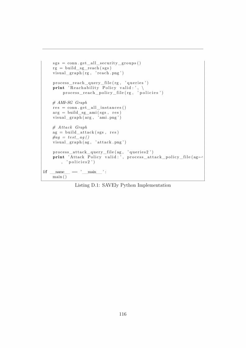
sg s = conn . get_al l_secur i ty_groups ( )rg = build_sg_reach ( sgs )visual_graph ( rg , ’ reach . png ’ )
process_reach_query_f i l e ( rg , ’ q u e r i e s ’ )print ’ Reachab i l i t y Po l i cy v a l i d : ’ , \
p roce s s_reach_po l i cy_f i l e ( rg , ’ p o l i c i e s ’ )
# AMI−SG Graphr e s = conn . ge t_a l l_ ins tance s ( )arg = build_sg_ami ( sgs , r e s )visual_graph ( arg , ’ ami . png ’ )
# Attack Graphag = bui ld_attack ( sgs , r e s )#ag = tes t_ag ()visual_graph ( ag , ’ a t tack . png ’ )
process_attack_query_f i l e ( ag , ’ que r i e s 2 ’ )print ’ Attack Po l i cy v a l i d : ’ , p roce s s_at tack_po l i cy_f i l e ( ag←↩
, ’ p o l i c i e s 2 ’ )
i f __name__ == ’__main__ ’ :main ( )
Listing D.1: SAVEly Python Implementation
116


![Automated Hadoop cluster deployment on clouds with … · Automated Hadoop cluster deployment on clouds with Occopus Enikő Nagy József Kovács Róbert Lovas [robert.lovas@sztaki.mta.hu]](https://img.dokumen.tips/doc/110x75/5afa1b407f8b9a19548d843c/automated-hadoop-cluster-deployment-on-clouds-with-hadoop-cluster-deployment.jpg)