Embed Size (px)
Citation preview

Automated Loading and Unloading System for Getinge USA Corporation
Preliminary Design Review Report
November 14, 2003 Thanasis Gkourlias
Derek Arnold Lawrence Derdzinski
Amber Mescher Chris Sangster
2
Executive Summary This Preliminary Design Review Report defines the design of the Automated Loading and Unloading System for Getinge Corporation. The Automated Loading and Unloading System will be a self-guided, fully automated, robot type product that is capable of loading and unloading medical carts of various sizes into Getinge's washing machines. This system will be a stand-alone product to be offered as an option to, and interface with, the Getinge Model 7800 Floor Loading Cart Washer. The robotic device will transport the carts to a washing machine, mainly used in hospitals. The goal of this project is to design, fabricate, debug, demonstrate, and potentially field test this automated system (robot) to prove its ability to load and unload medical carts. The Automated Loading and Unloading Team designed all aspects of the robotic solution. This includes the robot frame (housing), wiring, controls, integration and operator interface, drive system, docking and latching, tracking and charging system. The product will safely operate within a hospital central supply environment. The existing automated systems, which this system will face, require digging on the floor and installing big components to lead the cart into the washing machine. In opposition to the existing systems, the new Automated Loading and Unloading System is going to be compact, flexible, safe, easy to move, and reprogrammable. The team implemented the Engineering Design Planner methodology to design the robot. There are five design stages of the process. The first stage of the report, recognizing and quantifying the need, discusses the goals, motivation, and background of the project. The second stage presents an overview of four concepts the team has developed. The next stage presents the feasibility assessment the team conducted for each of the four concepts. The fourth stage presents a detailed description of the goals of the project as well as specifications of the design. The fifth stage, describes the analysis that has been done to design the automated system. Finally, the description of the experiments that will be performed next quarter, and a presentation of the plan for finishing the project on schedule and within budget will be performed. Technical data is also included, along with the summary of the current status of the project. The robot design continued to refine as multiple and often parallel activities occurred. That is, as brainstorming, customer requirements, feasibility studies, and technology searches continued to be refined, the design solidified. The initial design did not turn out to be the final design The final design of the robot is shown in the drawings included in the technical data package. The package has both assembly drawings as well as part drawings. The robot will be tested next quarter to validate that the robot meets the design objectives and specifications.

3
Table of Contents Executive Summary ..........................................................................................................2 Table of Contents..............................................................................................................3 List of Illustrations............................................................................................................5 1.0 Recognize and Quantify the Need ..............................................................................6
1.1 Project Mission Statement ...................................................................................6 1.2 Product Description .............................................................................................6 1.3 Scope Limitations ................................................................................................8 1.4 Stake Holders.......................................................................................................9 1.5 Key Business Goals ...........................................................................................10 1.6 Top Level Critical Financial Parameters ...........................................................10 1.7 Financial Analysis .............................................................................................10 1.8 Primary Market..................................................................................................11 1.9 Secondary Market..............................................................................................11 1.10 Order Qualifiers .................................................................................................11 1.11 Order Winners ...................................................................................................11 1.12 Innovation Opportunities ...................................................................................12 1.13 Background Research ........................................................................................12
2.0 Concept Development...............................................................................................15 2.1 Building vs. Buying ...........................................................................................15 2.2 Cart Towing Concept.........................................................................................16 2.3 Power System Concept ......................................................................................16 2.4 Control System Concept ....................................................................................17 2.5 Drive System Concept .......................................................................................17 2.6 Navigation System Concept ..............................................................................17 2.7 Communication System Concept ......................................................................18 2.8 Cart Detection System Concept.........................................................................18 2.9 Retro Fit Concept...............................................................................................18 2.10 Concept Development Conclusion ....................................................................19
3.0 Feasibility Assessment..............................................................................................20 3.1 Building vs. Buying ...........................................................................................20 3.2 Cart Towing Feasibility .....................................................................................21 3.3 Power System Feasibility ..................................................................................21 3.4 Control System Feasibility ................................................................................22 3.5 Drive System Feasibility....................................................................................22 3.6 Navigation System Feasibility...........................................................................22 3.7 Communication System Feasibility...................................................................23 3.8 Cart Detection System Feasibility .....................................................................23 3.9 Retro Fit Feasibility ...........................................................................................23 3.10 Feasibility Conclusion .......................................................................................24
4.0 Performance Objectives and Specifications..............................................................25 4.1 Design Objectives..............................................................................................25 4.2 Performance Specifications ...............................................................................26 4.3 Design Practices Used by the Team ..................................................................29 4.4 Safety Issues ......................................................................................................29

4
5.0 Analysis of Problem and Synthesis of Design .........................................................31 5.1 Cover Design .....................................................................................................31 5.2 Mounting............................................................................................................31 5.3 Control System ..................................................................................................32 5.4 Drive System .....................................................................................................32 5.5 Navigation System.............................................................................................35 5.6 Retro Fit ............................................................................................................36 5.7 Power Supply Selection.....................................................................................36 5.8 Charging System................................................................................................37 5.9 Cart Towing .......................................................................................................37 5.10 Cart Recognition................................................................................................39 5.11 Analysis Conclusion ..........................................................................................40
6.0 Future Plans ..............................................................................................................41 6.1 Experimentation.................................................................................................41 6.2 Schedule.............................................................................................................42 6.3 Budget................................................................................................................42
7.0 Conclusion ................................................................................................................43 References ......................................................................................................................45 Appendix.........................................................................................................................47

5
List of Illustrations
Figure 1.1: Belimed Automated Loading and Unloading System ........................................12 Figure 1.2: Tug in Action.......................................................................................................13 Figure 2.1: Two-pin Robot Design ........................................................................................16 Figure 5.1: Top and Bottom Frame Views ...........................................................................31 Figure 5.2: Drive System of Robot ......................................................................................32 Figure 5.3: Calculations for Weight Distribution ..................................................................33 Figure 5.4: Calculation of Drive Motor Torque and Power...................................................34 Figure 5.5: Calculation of Current Drawn from the Motors..................................................35 Figure 5.6: Cubic Screw Jack Sizing .....................................................................................38 Figure 5.7: Screw Jack Motor Current Drawn.......................................................................39 Figure 5.8: Overall Design of Robot......................................................................................40 Figure 6.1: Spring Quarter Schedule .....................................................................................42

6
1.0 Recognize and Quantify the Need 1.1 Project Mission Statement The Automated Loading and Unloading System Senior Design Team is to design and
fabricate a working prototype in conjunction with Getinge USA. This prototype will be
used to help hospitals manage their personnel. This will allow the hospital washing area
to be more efficient, leaving more personnel for other needs. A secondary goal of the
project is to release the system in conjunction with the new Getinge 7800 series washer,
which will be released in October 2004.
1.2 Product Description
One of the most significant problems in designing a competitive Automated Loading and
Unloading System for hospital medical cart washers is their bulk. This bulk takes up
valuable room in a hospital cleaning area. Based on customer feedback, Getinge USA
needed an Automated Loading and Unloading System that will be a self-guided, fully
automated, non-invasive, robot type product. The system should also be capable of
loading and unloading large, floor mounted, washing machines with medical carts of
various sizes and weights. The system is intended to be a stand-alone product to be
offered as an option to, and interface with, the Getinge 7800 Floor Loading Cart Washer.
There must be two robots, one for loading the medical carts on the soiled side of the
washer, and another for unloading the medical carts on the clean side of the washer. This
is needed because the robot cannot go between the two areas without causing
contamination.

7
The advantage of a robot type loading and unloading system is that it takes up much less
of the valuable hospital floor space than the other systems available today. It can also
take the place of a staff member of the hospital so that they can be doing something more
valuable then just loading a medical cart washer.
The Senior Design team used this idea to design a mobile robot. This design includes
concepts of the robot frame and covering, wiring, controls, drive system, docking and
latching systems, tracking system, safety system, charging system, integration, and
operator interface. The robot was designed to be small enough to fit underneath the
medical carts, to be powerful enough to pull the heavy medical carts, and be able to adapt
to latch on to medical carts of different heights.
The smallest medical cart has five and a half inches of clearance between the bottom of
the medical cart and the ground. The robot was designed to be fully functional and able
to traverse underneath even the smallest cart. The product specifications that Getinge
provided state that the robot needs to produce about fifty pounds of linear force besides
the force needed to pull its own weight. In order accomplish this and still fit under the
medical cart, the robot’s components, including batteries, motors, and the pin used to
connect to the medical cart needed to be very powerful and still less than four inches in
height. A pin will be raised from the robot into a universal locking mechanism on the
medical cart.
Since this is a mobile robot, the only power source available is battery power. We want
to be able to reuse the batteries, so each system will include a charging station where the
robot can charge during the wash cycle.
8
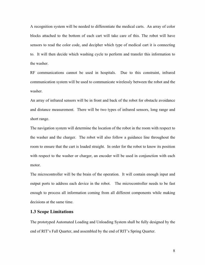
A recognition system will be needed to differentiate the medical carts. An array of color
blocks attached to the bottom of each cart will take care of this. The robot will have
sensors to read the color code, and decipher which type of medical cart it is connecting
to. It will then decide which washing cycle to perform and transfer this information to
the washer.
RF communications cannot be used in hospitals. Due to this constraint, infrared
communication system will be used to communicate wirelessly between the robot and the
washer.
An array of infrared sensors will be in front and back of the robot for obstacle avoidance
and distance measurement. There will be two types of infrared sensors, long range and
short range.
The navigation system will determine the location of the robot in the room with respect to
the washer and the charger. The robot will also follow a guidance line throughout the
room to ensure that the cart is loaded straight. In order for the robot to know its position
with respect to the washer or charger, an encoder will be used in conjunction with each
motor.
The microcontroller will be the brain of the operation. It will contain enough input and
output ports to address each device in the robot. The microcontroller needs to be fast
enough to process all information coming from all different components while making
decisions at the same time.
1.3 Scope Limitations
The prototyped Automated Loading and Unloading System shall be fully designed by the
end of RIT’s Fall Quarter, and assembled by the end of RIT’s Spring Quarter.

9
At the end of the Fall Quarter, the senior design team will hold a Preliminary Design
Review. At this review the team will be responsible for:
• Complete design of the system
• Drawing Package
• Software flow charts
• Bill of Materials
• Quotes for Vendors
• Budget
At the end of the Spring Quarter, the senior design team will present the debugged and
tested prototype. At this presentation they will be responsible for:
• Working prototype
• Final Report / Binder
• Initial testing done using a medical cart and washer
The senior design team will not be responsible for the following:
• Washer Design
• Microcontroller Design
• PLC Integration
• Hospital Installation
1.4 Stake Holders
The main stakeholders are the students working on the design and the Getinge USA
Corporation. Other stakeholders are the hospitals and staff in which these system will be
integrated, and the future of Automated Loading and Unloading Systems.

10
1.5 Key Business Goals
The team will be successful when they have designed a working Automated Loading and
Unloading System that requires very little human interaction. If this has been done:
• The students on the team will have learned how to work on a multidisciplinary
team.
• A proof of concept will have been completed and further can be requested for
future prototypes.
• Getinge with have an advantage on the other medical cart washer production
companies, and could profit immensely.
1.6 Top Level Critical Financial Parameters
• Given the decision to have the robot travel under the medical carts, will cause a
need for smaller components at higher prices. The components that will cause the
most concern are the batteries, motors, and screw jack.
• The scope of the project will require our robot to be very robust, which can be
costly. It will need to have reliable parts and certain aspects to withstand the
environment of the hospital, which may not have been considered in other
environments.
1.7 Financial Analysis
A $10,000 budget has been appropriated for the cost of producing one robot. This budget
shall include:
• Motors, Gearboxes, and Encoders
• Electronics
• Wheels

11
• Attachment System
• Batteries and Battery Charger
• Sensors
• Chassis, and Body
• Wires, Bolts, and Hardware
1.8 Primary Market
The primary market of the Automated Loading and Unloading System is hospitals with
Getinge 7800 Floor Loading Washing Machines.
1.9 Secondary Market
The Automated Loading and Unloading System could very easily be adapted to other
environments where a cart needs to be moved.
1.10 Order Qualifiers
The Automated Loading and Unloading Team shall fabricate, assemble, and program a
prototype that will load a medical cart into the Getinge 7800 Series washer. The team
will also do experimentation to verify the power and efficiency of the robot.
1.11 Order Winners
The following are the goals of the project if time and budget permit:
• Be small enough to fit underneath the smallest of the medical carts.
• Be sufficiently powerful to pull the heaviest medical cart that is specified.
• Be sufficiently reliable as defined in the specifications.
• Meet safety requirements as defined in the specifications.
• Have the need for very little human interaction.

12
• Be able to sense the location and type of medical cart.
• Verify that Engineering Design Models agree with prototype.
1.12 Innovation Opportunities
Potentially the Automated Loading and Unloading System could be used with a new
Getinge 7800 Series washer. Eventually, the Automated Loading and Unloading System
will be integrated into any hospital that uses a Getinge washing machine.
1.13 Background Research
The research completed by the Automated Loading and Unloading team consisted of
exploring systems in existence, robots on the market, and components.
Figure 1.1 - Belimed Automated System
Belimed makes a system where there is a track in front of the washer that pulls the
medical cart into and out of the washer. Steris also makes a system similar to this. The
problem with both of these systems is that they take up too much room in a hospital.
They also require a large amount of construction on the floor to install the system and
still require an operator. Getinge desired a solution that will not require a fulltime
operator or invasive floor construction.
13
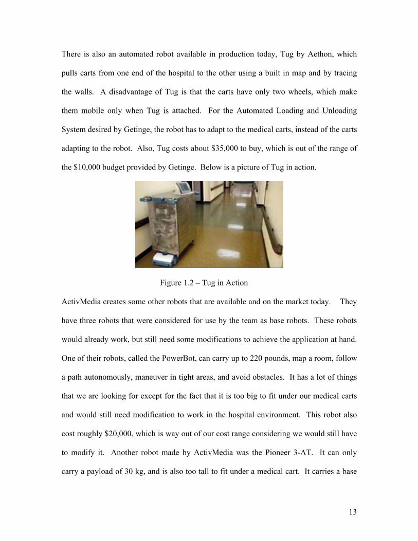
There is also an automated robot available in production today, Tug by Aethon, which
pulls carts from one end of the hospital to the other using a built in map and by tracing
the walls. A disadvantage of Tug is that the carts have only two wheels, which make
them mobile only when Tug is attached. For the Automated Loading and Unloading
System desired by Getinge, the robot has to adapt to the medical carts, instead of the carts
adapting to the robot. Also, Tug costs about $35,000 to buy, which is out of the range of
the $10,000 budget provided by Getinge. Below is a picture of Tug in action.
Figure 1.2 – Tug in Action
ActivMedia creates some other robots that are available and on the market today. They
have three robots that were considered for use by the team as base robots. These robots
would already work, but still need some modifications to achieve the application at hand.
One of their robots, called the PowerBot, can carry up to 220 pounds, map a room, follow
a path autonomously, maneuver in tight areas, and avoid obstacles. It has a lot of things
that we are looking for except for the fact that it is too big to fit under our medical carts
and would still need modification to work in the hospital environment. This robot also
cost roughly $20,000, which is way out of our cost range considering we would still have
to modify it. Another robot made by ActivMedia was the Pioneer 3-AT. It can only
carry a payload of 30 kg, and is also too tall to fit under a medical cart. It carries a base

14
price $5995, which is not totally out of our price range, but it would still require a lot of
modifications. The third robot that was considered from ActivMedia was the Pioneer 3-
DX. It’s not as powerful as the P3-AT, as it can only have a payload of 23 kg. This
carries a base price of $3695, and would also require a lot of modifications.
Angelus Research Corporations makes a robot called Whiskers the Intelligent robot. It
only costs $895, and is small enough to fit under a medical cart, but not strong enough to
pull it. It would also require a lot of major modifications to be able to meet the required
specifications.
Finally we found two robots made by Applied AI Systems, INC. called the LABO-2, and
the LABO-4. The LABO-4 costs $19,200 and has a payload of 90 kg. The LABO-2
costs $20,400 and has a payload of about 135 kg. Both of these robots have the type of
power that we are looking for, but both don’t fit in the size constraints that we need.

15
2.0 Concept Development
The Automated Loading and Unloading System team developed a large list of possible
ways of loading and unloading a medical cart into and out of the washer. This list can be
seen in the concept development part of the Engineering Design Planner binder. The list
of ideas originally contained 30 items. These ideas were discussed and voted on to create
a base of four ideas. The four most favorable ideas were: to design a robot with arms that
would surround the medical cart, to design a robot with a hook which would pull the
medical cart, to design a robot which would accept the pins from the medical cart, and to
design a robot which would lift the medical cart while accepting a pin. Group drawings
were formed and the ideas started the development stage.
2.1 Building vs. Buying
The main driving point of this project was being able to design the robot in ten weeks,
and being able to mass produce it after prototype. Getinge and the Automated Loading
and Unloading System design team discussed various options, which included, building
the robot from components, buying a robot base and adding components, and buying an
existent robot.
It was desirable to stay at a cost below $10,000 which devalued buying a complete robot.
Building the robot from components and building on top of an existing robot base were
both considered. The decision to build from components came about due to the available
bases not meeting the constraints of the project.

16
2.2 Cart Towing Concept
A major aspect of the design was determining how to move the medical cart. The team
decided that the most favorable way to move the medical cart would be by having the
robot attach to two pins dropping down from the medical cart.
Figure 2.1 Two-pin Robot Design
As this idea grew, so did the size of the robot. The robot changed from fitting entirely
under the medical cart to fitting partially under the medical cart to make enough room for
a camera, Ultrasonic sensors, motors, and various other parts. This idea was developed
and presented to the customer. For various reasons to be discussed in the feasibility
section, the customer suggested a different design. This design was a robot that fit under
the medical cart and shot a pin into a hole on the mounting bracket attached to the
medical cart. The robot would lift the medical cart and pull it by this pin.
2.3 Power System Concept
One constraint was that the robot must be a mobile robot. This led to the robot being
powered by batteries with a charging station. There will be multiple batteries to provide
enough power to drive the motors, run sensors continuously, and keep the microcontroller
working. The robot will return to the charging area during each wash cycle. The

17
charging area will be mounted on the wall to avoid obstruction and to provide a safe
environment.
2.4 Control System Concept
The initial plan for the control system was to modify one that already existed. The
control system desired was the Whisker board available from Angelus research. This
board was going to be used as the base control and another microcontroller was to be
piggybacked on top of it to provide ample inputs and outputs. The microcontroller was to
handle the inputs and outputs of all sensors along with motor encoders. As the quarter
progressed, experiments were done with the whisker robot, and it was found to be not as
reliable as desired. The company was researched further and considered to not be a
reliable company. The control design was then changed to one microcontroller with
ample inputs and outputs.
2.5 Drive System Concept
The four-wheeled robot will need to be directed as it travels throughout the hospital. The
drive systems considered were 4 drive wheels, 2 drive wheels and 2 casters, and 2 drive
wheels 2 stationary wheels. Each system was considered and simulated.
2.6 Navigation System Concept
The robot will “see” as it navigates throughout the room. The camera will be the primary
controller for navigation of the robot. It will recognize certain objects that have been
preprogrammed into it. There will also be arrays of infrared sensors for obstacle
avoidance and distance determination. The robot will follow a certain array of lines on
the floor to travel throughout the room and to ensure that it enters the washer straight.

18
There will be an array of IR sensors on the top of the robot, which detect the proper
position for the pin to enter the cart.
2.7 Communication System Concept
Since there is no RF communication allowed in the hospital, the communication will
occur with infrared transceivers along with a wired connection. The wired connection
will communicate between the washing machine and the charging station. The infrared
transceivers will communicate between the robot-washing machine and robot-charging
station. The transceivers will inform the washer when the medical carts are loaded and
tell the washer what cycle to perform. The charging station will tell the robot when there
is a certain amount of time left in the washing cycle. From this communication, the robot
will know when to get a cart and when to load it into the washing machine.
2.8 Cart Detection System Concept
The medical cart will be detected in multiple stages. The initial detection of the medical
cart will come from the camera, so that the robot knows to retrieve that medical cart. The
second line of detection will be a series of infrared sensors on the top of the robot that
will read what type of medical cart it is and what washer cycle to perform.
2.9 Retro Fit Concept
One major constraint of the robot was that there had to be a universal kit to go on every
medical cart. This retro fit concept developed into a plate across the front wheels with a
hole for the pin, along with the black and white blocks for the infrared sensors to read to
determine the cart type. On the rear wheels, there will be spacers to ensure that the
medical cart stays level. This module will mount directly to the case medical carts and
will mount on a lowering bracket of the wire medical carts. There will be different black
19
and white block schemes for different cart types to distinguish between the medical carts
and laundry cycles.
2.10 Concept Development Conclusion
The preliminary design concept is a robot that will travel under the medical cart, raise a
pin into the medical cart and pull the medical cart into the washer. The robot will be
powered by batteries and built from components stated previously. The drive system will
consist of two motors with encoders to drive each wheel separately in a skid/steer design.
There will be one microcontroller to control the robot. This microcontroller will handle
both the input and the output of the sensors and motor encoders. The navigation system
of the robot will consist of a camera and infrared sensors for distance measurement and
object avoidance. Communication will be provided to and from the robot by infrared
transceivers and between the charging station and washing machine by a hardwire
connection. The robot will detect types of medical carts by an array of infrared sensors.
Each medical cart will have a harness to which the robot will mount. This will make for
a complete system.

20
3.0 Feasibility Assessment
Feasibility was assessed using two methods. One method was the Pugh’s method where
four designs are compared against the base design. This method produces results that are
not always accurate because no aspect of the design is weighted more than the others.
The second method used for feasibility assessment was a weighted method. This method
proved to be much more accurate as it weighted the most important factors over the less
important factors.
3.1 Building vs. Buying
The way the robot was produced was a great factor in the design of the robot. The three
choices that were considered were building the robot from scratch, buying a robot base
and adding components, and buying an existing robot. The first case considered was
buying an existing robot. While this was by far the quickest solution to the company’s
desires, it did not meet the requirements in cost. The lowest priced robot was found to be
$35,000, while the robot budget was $10,000. It also did not leave any room for
adaptations to this specific project.
The second idea considered was buying a robot base, and adding components to it. This
idea was entertained for a bit, as it would make programming and testing much easier,
since there was a guarantee that the robot would work. This idea however, began to fall
through when no bases were found that were suitable for the application. The price was
also a factor as the robot bases that were found were around $10,000, which would not
leave much room for any additions.
The last idea considered was building the robot from components. This strategy will
require more work and time to create a working model, but it does give the flexibility

21
needed. This is also the only option that has a chance of being under the $10,000 budget
provided.
3.2 Cart Towing Feasibility
Four options were initially considered to tow a medical cart. These options were pulling
and lifting with one pin, pulling with two pins, hooking onto the medical cart, and
grabbing the medical cart from the side. As the ideas developed, grabbing the medical
cart from the side was voted out due to the massive amount of fragile material that would
be present in the arms. The hook idea was seriously considered due to the fact that a
retrofit kit would not be needed, but it was unsure how a medical cart could be moved
backward easily with a hook. The one pin and two-pin design were seriously considered
and designed. The two-pin design won over the one pin design because of the
controllability in turning. The two-pin design was presented to the customer who
expressed doubts in the ability to produce the amount of torque necessary to turn the
medical cart. The customer favored a design much like the one pin design, except that
they wanted the pin to come up from the robot instead of down from the medical cart.
Although this would make steering a bit tricky, it was worth the cost of being able to
travel completely under any medical cart.
3.3 Power System Feasibility
The most beneficial power source was determined to be batteries. These batteries could
either be lead acid, or Nickel-Lithium. Lead acid batteries were selected due to their
weight and ability to short cycle. Nickel-Lithium batteries required a very long amount
of charging time, and became unpredictable when not charged completely. They were
also very hard to find at large voltages and larger currents needed for the motors. Lead

22
acid batteries were available in many voltages and many currents. They can be charged
for a short amount of time and also add weight to the robot for traction.
3.4 Control System Feasibility
The microcontroller for the desired robot required as many inputs and outputs as possible.
The initial microcontroller to be used was the whisker robot controller. This was found
to be inadequate because it did not have enough input or output pins for all of the sensors.
It was also found that the company was not very reliable and the software was not
sufficient. The microcontroller that was chosen was had more than enough input and
output lines and could control everything necessary. It also has a development board and
sufficient software and support.
3.5 Drive System Feasibility
The drive systems considered for the robot were four separate drive wheels, two sets of
two drive wheels, and two drive wheels - two caster wheels. The four separate wheel
drive was deemed to be too hard to control and not needed in this application. The
scheme of two sets of two drive wheels was considered, but it was decided that it was not
necessary in this application. The drive system that was decided upon was two drive
wheels and two caster wheels. This system made turning at any radius easy, while the
caster wheels support the weight of the robot and the medical cart.
3.6 Navigation System Feasibility
The navigation system of the robot was one of the most important parts of the robot. The
choices for navigation were a camera, ultrasonic sensors, and infrared sensors. The
camera was initially going to be used for medical cart detection. It was later realized that
the camera could do navigation along with object detection. The ultrasonic sensors were

23
going to be used as object avoidance, however in the new design of the robot, there was
no room and no need for the ultrasonic sensors. The infrared sensors were the hardest
sensors to place on the robot. These sensors are very limited in the amount of space that
they can see. The infrared sensors are going to be used to find the end of the washer
along with close obstacle avoidance and reading medical cart types.
3.7 Communication System Feasibility
The three types of communication systems considered were RF transmission, infrared
transmission, and wired transmission. RF transmission was ineligible, as it is not allowed
in the hospital. The Infrared transmission was used to communicate between the robot
and the washer and the robot and the charging station in place of the RF communication.
The charging station will also be able to communicate with the washer through a hard-
wired connection.
3.8 Cart Detection System Feasibility
Detecting a medical cart may be one of the most challenging aspects of the design. The
object attributes of the medical carts are its existence and its type. The initial medical
cart detection was to be camera technology. With the new design where the robotic
device must fit under the medical cart, the camera does not have the scope to detect the
medical cart. As an added detection infrared sensors will determine what the type of
medical cart, which in turn determines which wash cycle to perform.
3.9 Retro Fit Feasibility
Retro fitting the medical carts was something that was very important to the customer.
They have many medical carts in hospitals unable to be replaced. The most efficient
solution was to add a bracket to the medical cart for the robot to attach to, instead of

24
changing the way the medical carts are made. This allows for all medical carts to be
accessed by the robot and by a human. The kit will be attached between the front wheels.
This simplifies the robotic controls as well as cut down on the number of modifications
necessary to the medical cart.
3.10 Feasibility Conclusion
The feasibility analysis was defined, refined, and validated by weekly meetings with
Getinge management. Their knowledge of the hospital environment and our constant
brainstorming helped shape the final feasibility model.

25
4.0 Performance Objectives and Specifications
The objectives and specifications define “what is needed” and “how well” the solution
will perform. The performance objectives and specifications were customer defined to
meet their market place needs.
4.1 Design Objective
There are a number of design objectives that must be met.
• This product shall be self-guided and fully automated.
• This product shall be capable of loading floor-mounted washing machines with
medical carts of various sizes.
• There will be two robots per system. RIT will design and prototype the loading
side robot and if time permits, the unloading side robot.
• The system must be a stand-alone product that will interface with the Getinge
Model 7800 Floor Loading Cart Washer.
• The system must have the capability of detecting the presence of a medical cart in
the load and unload staging areas.
• The system must have the capability of detecting the presence of the washer.
• The product must identify medical cart type.
• The system must have a manual override. (This is important in the case of an
emergency and service.)
• This system must be rechargeable.
• There must be a charging/docking station mounted in the area where the robot can
be recharged.
• The robot must also be able to detect the amount of energy left in its fuel cells.

26
• The robot must also be able to charge itself automatically
• The medical carts that the robot will be loading into the washer must be modified
so that the robot can safely attach to and navigate them throughout the hospital.
• The system will be configurable to three 7800 Cart Washer models based on load
length.
• The robot will be protected (i.e. circuit breakers) to minimize any chance of fire
or smoke generation.
4.2 Performance Specifications
There are certain performance specifications that must be met in order for the project to
be successful. The system was designed around these specifications. They are listed
below:
A. NO PIT REQUIREMENTS
The design will not require any pits or holes that must be dug into the floor of the
hospital.
B. EXTERIOR SURACFE-304 STAINLESS STEEL
The exposed exterior surfaces of the robot is to be type 304 stainless steel with a
standard #3 finish. This will match the surface of the medical cart washers and will
be able to withstand the heat and hot water that will be inside of the washer. The
exterior surface must also be smooth and free of snag points to facilitate wipe-down
cleaning.
C. 50 POUNDS OF LINEAR FORCE
The robot must provide 50 pounds of linear force in order to move the medical carts.
D. 100 POUND LOAD

27
The robot must be designed to operate with a 100-pound load on top.
E. EASILY REMOVABLE COVER
The cover of the robot must be easily removable so that maintenance and service can
easily de done to the robot.
F. SIZE
The robot must be sized for compatibility with healthcare industry standard case and
surgical medical carts. The robot must be able to travel underneath a medical cart.
G. SERVICE SPACE
No service space is to be required from within or behind the wall mounted
components or from below floor mounted components (no pit).
H. CYCLE TIME
The automated system is to be capable of loading or unloading one medical cart in
one minute or less. Time measured from the robot leaving till it’s return to a charging
station located no more that three feet (914 mm) from the washer door opening.
I. SUPPLY VOLTAGE
The system must be capable to operate on 120 V, single phase, 50/60 Hz.
J. OPERATED BY GE VERSA-MAX PLC
The automated system is to be operated by a GE Versa-Max Programmable Logic
Controller. The operator interface is a 6” TCP color touch panel display. Using this
touch panel the operator will be able to accomplish the following:
• Start the automated processing cycle
• Monitor the process status of automated operations
• Stop automated process

28
• Start washer processing with partially loaded chamber
K. OPERATING AMBIENT CONDITIONS
The system must be able to operate under these conditions:
• Temperature: 10°C (50°) to 40°C (104°F)
• Pressure: Atmospheric from 0 to 2000 m (6500ft)
• Relative Humidity: 10 to 90 % non condensing
• Pollution degree: 2
L. STORAGE AND SHIPPPING
The system must be able to be packed and shipped in the following conditions:
• Temperature: -18°C (0°F) to 60°C (140°F)
• Pressure: Atmospheric from 0 to 3690 m (12000 ft)
• Relative Humidity: 10 to 90 % non condensing
• Package robot is to survive conditions experienced in the shipping process
without damage.
M. REGULATORY & CODE COMPLIANCE
The product is to be designed to meet requirements of the latest edition of the
following standards:
• UL-3101-1, Certified by ETL Testing Laboratories
• CSA C22-2 No. 1010.1, Certified by ETL Testing Laboratories
• FCC
• Seismic requirements per California Administrative Code
N. RELIABILITY AND LIFE EXPECTANCY

29
With utilities within specified limits and factory recommended maintenance
schedules, the system shall be designed to function properly without failure or need
for repair for a minimum of 12 months from the date of installation. (3 cycles/hr. x
12 hrs./day x 6 days/week x 50 weeks/yr. = 10,800 cycles considered 12 month
usage)
4.3 Design Practices Used by the Team
There were many design practices that were considered by the team. A list of these
practices are listed below:
• Design for Manufacturability- The system was designed so that all needed parts
are readily available and the system shall be easily manufactured.
• Design for Safety- The product was designed to comply with all the safety codes
and specifications.
• Design for Efficiency- The team designed the system to be as efficient as possible
and output as many cycles as possible.
• Design for Reliability- The system was designed to be reliable and not to need
constant maintenance and service. It was also designed to meet the 12-month
failure requirement.
• Design for Cost- The team designed the robot to be competitive with the pricing
of robots that are already available. It was also designed to have a manufacturing
cost of $10,000.
4.4 Safety Issues
Since this system is made for use in a hospital, there are many safety measurements that
must be met. They are listed below:

30
• Any floor mounted locating and detection devices to be such as to not be trip
hazards to operators.
• Audible and visual alarms during any movement of the robot.
• System to be capable of detecting obstructions and subsequently stopping
motions. Manual restart is required to resume operation.
• Emergency stop switch located on robot and control console.
• Automated system to deactivate when 7800 Cart Washer is in “fault mode”.
• In the event of a power failure, the control system shall retain current cycle
information for a minimum of 30 days.
• Upon power restoration, the controller will revert to standby status. If power loss
occurs during a cycle, a cycle not completed message will also be displayed.
• If a detectable system failure or malfunction occurs, the controls will go into a
known safe state.
• Failure and malfunction messages shall be displayed in order of occurrence and
printed.
• An audible warning shall sound whenever a failure message is displayed.
• In the event of an automatic abort resulting in am incomplete cycle, the operator
must restart the system. The unit will not start automatically if a fault is cleared.

31
5.0 Analysis of Problem and Synthesis of Design Final designs were created for each component of the robot. After these designs were
made, specific parts were selected to ensure proper assembly. Specific calculations were
performed to determine the requirements of components chosen. The robot drawings
started taking shape as the components were placed inside.
5.1 Cover Design The cover consists of four pieces of type 304 stainless steel with a #3 finish. The top
piece shall be connected to the top of the frame with a hinged back and two screws in the
front for easy, yet controlled access. The lower portion of the cover will consist of the
bottom and sides. The front and back will remain attached to the frame and will support
the sensors and charging receptors.
Figure 5.1 – Top and Bottom Frame Views
5.2 Mounting
The mounting system will consist of screws and standoffs for the circuit boards. Pan head
bolts recessed into the mounting bracket will secure the motors. The batteries will be
secured to the frame by straps wrapped around the top of the batteries.
32
5.3 Control System
The Control system is the C805F120 made by Cygnal (www.cygnal.com). The selection
of this control system was based on the requirements of the video and infrared navigation
systems, which will require these features. This controller meets or exceeds memory
requirements (i.e. 128k flash and 8.25K RAM). Robotic performance will be support by a
100 MHz processor. The other selection factor for the control system was the number of
I/O ports required to accommodate the quantity of proximity sensors required for obstacle
avoidance. The control system comes with the microcontroller, a development board,
and development software. This enables integration of the electronic parts into the robot.
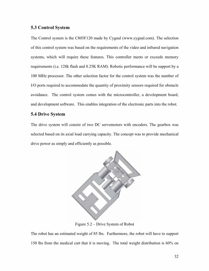
5.4 Drive System
The drive system will consist of two DC servomotors with encoders. The gearbox was
selected based on its axial load carrying capacity. The concept was to provide mechanical
drive power as simply and efficiently as possible.
Figure 5.2 – Drive System of Robot
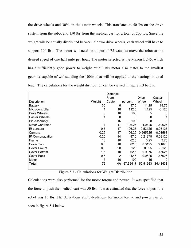
The robot has an estimated weight of 85 lbs. Furthermore, the robot will have to support
150 lbs from the medical cart that it is moving. The total weight distribution is 60% on
33
the drive wheels and 30% on the caster wheels. This translates to 50 lbs on the drive
system from the robot and 150 lbs from the medical cart for a total of 200 lbs. Since the
weight will be equally distributed between the two drive wheels, each wheel will have to
support 100 lbs. The motor will need an output of 75 watts to move the robot at the
desired speed of one half mile per hour. The motor selected is the Maxon EC45, which
has a sufficiently good power to weight ratio. This motor also mates to the smallest
gearbox capable of withstanding the 100lbs that will be applied to the bearings in axial
load. The calculations for the weight distribution can be viewed in figure 5.3 below.
Description Weight
Distence From Caster percent
Drive Wheel
Caster Wheel
Battery 30 6 37.5 11.25 18.75Microcontroller 1 18 112.5 1.125 -0.125Drive Wheels 5 16 100 5 0Caster Wheels 1 0 0 0 1Pin Assembly 8 16 100 8 0Motor Controler 1 17 106.25 1.0625 -0.0625IR sensors 0.5 17 106.25 0.53125 -0.03125Camera 0.25 17 106.25 0.265625 -0.01563IR Comunacation 0.25 14 87.5 0.21875 0.03125Frame 10 10 62.5 6.25 3.75Cover Top 0.5 10 62.5 0.3125 0.1875Cover Frount 0.5 20 125 0.625 -0.125Cover Bottom 1.5 10 62.5 0.9375 0.5625Cover Back 0.5 -2 -12.5 -0.0625 0.5625Motor 15 16 100 15 0Total 75 NA 67.35417 50.51563 24.48438
Figure 5.3 - Calculations for Weight Distribution
Calculations were also performed for the motor torque and power. It was specified that
the force to push the medical cart was 50 lbs. It was estimated that the force to push the
robot was 15 lbs. The derivations and calculations for motor torque and power can be
seen in figure 5.4 below.
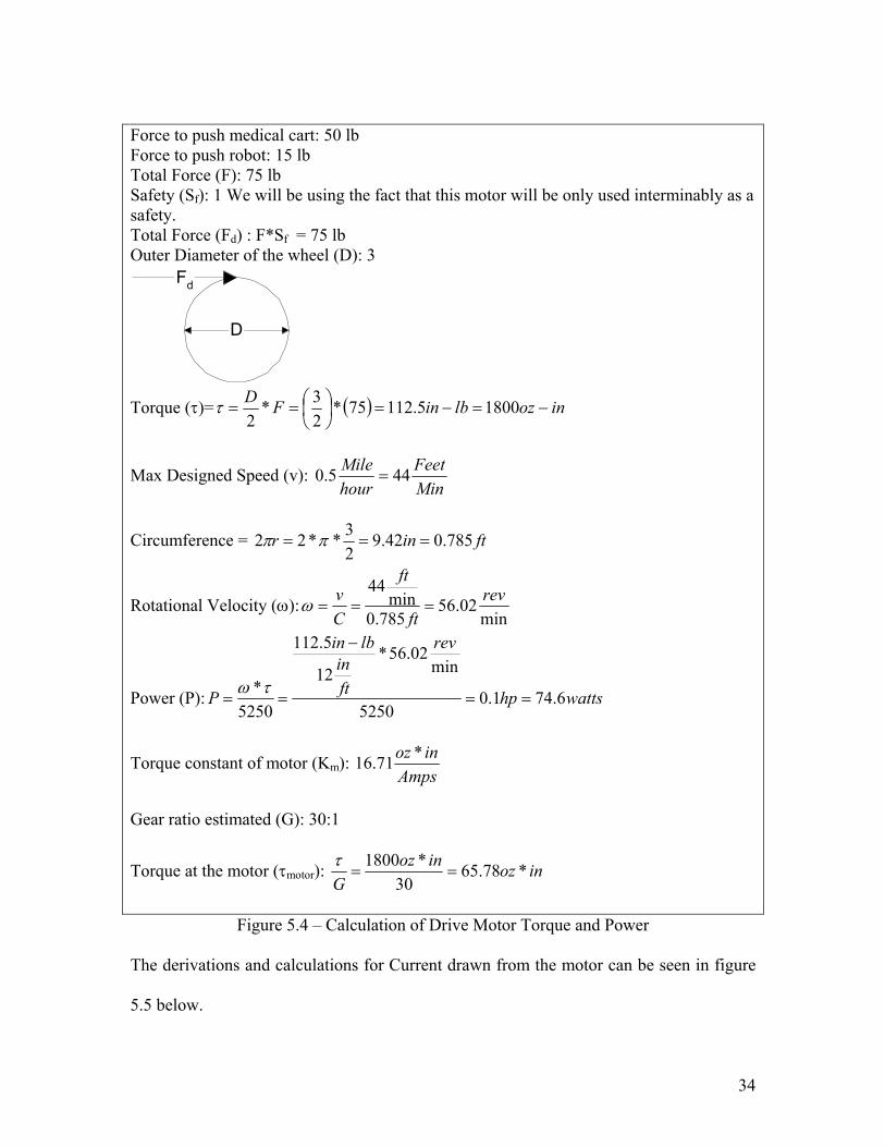
34
Force to push medical cart: 50 lb Force to push robot: 15 lb Total Force (F): 75 lb Safety (Sf): 1 We will be using the fact that this motor will be only used interminably as a safety. Total Force (Fd) : F*Sf = 75 lb Outer Diameter of the wheel (D): 3
Fd
D
Torque (τ)= ( ) inozlbinFD−=−=
== 18005.11275*
23*
2τ
Max Designed Speed (v): MinFeet
hourMile 445.0 =
Circumference = ftinr 785.042.923**22 === ππ
Rotational Velocity (ω):min
02.56785.0
min44 rev
ft
ft
Cv
===ω
Power (P): wattshp
rev
ftin
lbin
P 6.741.05250
min02.56*
12
5.112
5250*
==
−
==τω
Torque constant of motor (Km): Amps
inoz *71.16
Gear ratio estimated (G): 30:1
Torque at the motor (τmotor): inozinozG
*78.6530
*1800==
τ
Figure 5.4 – Calculation of Drive Motor Torque and Power
The derivations and calculations for Current drawn from the motor can be seen in figure
5.5 below.
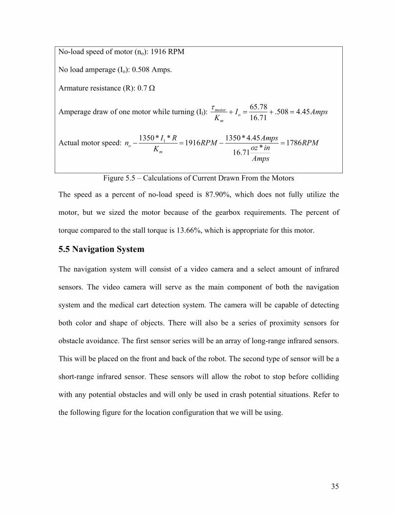
35
No-load speed of motor (no): 1916 RPM No load amperage (Io): 0.508 Amps. Armature resistance (R): 0.7 Ω
Amperage draw of one motor while turning (Il): AmpsIK o
m
motor 45.4508.71.1678.65
=+=+τ
Actual motor speed: RPM
Ampsinoz
AmpsRPMK
RInm
o 1786*71.16
45.4*13501916**1350 1 =−=−
Figure 5.5 – Calculations of Current Drawn From the Motors
The speed as a percent of no-load speed is 87.90%, which does not fully utilize the
motor, but we sized the motor because of the gearbox requirements. The percent of
torque compared to the stall torque is 13.66%, which is appropriate for this motor.
5.5 Navigation System
The navigation system will consist of a video camera and a select amount of infrared
sensors. The video camera will serve as the main component of both the navigation
system and the medical cart detection system. The camera will be capable of detecting
both color and shape of objects. There will also be a series of proximity sensors for
obstacle avoidance. The first sensor series will be an array of long-range infrared sensors.
This will be placed on the front and back of the robot. The second type of sensor will be a
short-range infrared sensor. These sensors will allow the robot to stop before colliding
with any potential obstacles and will only be used in crash potential situations. Refer to
the following figure for the location configuration that we will be using.

36
5.6 Retro Fit Kit
There will be a number of different Retro Fit Kits necessary for the varying medical cart
designs available. There will be some design characteristics that will be consistent
thought the versions. The piece that the robot will see will be the same on every cart.
This piece will consist of a hole in the center of the bracket. This hole will receive the pin
from the robot.
The mounting system will attach to the top of the caster wheels through the existing holes
for the wheel bolts. The wheels will be removed; then the bracket will be added and the
wheels will be reinstalled. In the case of the wire frame cart, this method will not work.
In this case we will have a bent piece of metal over the support bars to secure the bracket
to the medical cart. This will allow the bracket to be at the same height for all carts.
5.7 Power Supply Selection
The power supply system will consist of four 12-volt lead acid batteries. The advantage
of lead acid batteries is that the battery can be recharged when the robot has a time and
does not require a complete cycle for continued battery performance. The voltage
required to power the motors is 24 volts therefore the batteries will be grouped with two
sets of parallel linked batteries wired in series giving the necessary voltage and current.
Due to size constraints, grouping the 12-volt batteries created the 24-volts necessary.
The current capacity of theses batteries is 12AH since we will be using 4 of them at 24
volts we will have a total of 24AH with an estimated 7Amp power drain we will have 3.4
hours of continuous operation. The robot will operate for an estimate of 2 minutes out of
every ten minutes or 20% of the time. This should allow the robot to operate for a 16-18
hour day without the need for recharging, which is much more than the specifications call

37
for.
5.8 The Charging System
The Charging system will consist of a standard 24V battery charger, communications
chip and a plug system. The battery charger will need to have the circuits to properly
charge and maintain the batteries. The plug will consist of two posts that will stick out
from the charger; this is where the robot will connect to the charger. The plugs will have
springs on them to keep them tight against the robot. The robot will have receptors
consisting of isolated plats of metal that will receive the power.
5.9 Cart Towing
Hitching to the front of the medical cart and then pulling the medical cart into position
will accomplish the towing. The biggest concern will be for the radius of turning. The
medical cart wheels can be as close as fourteen inches between inside edges. The robot is
12 inches wide, which means that the robot can only rotate 36 degrees off of center.
After the medical cart is positioned in the washer, the robot will detach and drive out
from under the medical cart. Upon departure of the washer, the robot will signal the
washer to commence with the wash cycle or retrieve the second medical cart. The system
to lift the cart will consist of a cubic screw jack combined with a DC motor. We chose
the cubic screw jack due to its size and large lifting capacity. The calculations to size the
cubic screw jack can be see in figure 5.6 below.

38
Actual Force (Feff): 150 lbs=0.667kN
Transmission Ratio: revmm
iP 25.=
Efficiency: η=25%
Idle Torque (MO): .03 N*m
Required Drive Torque (MT):
mNmNmkNMiPFeffM OT ==+=+= 4.19*136.0*03.25.*
14.3*25.*2*667.*
**2 ηπ
Power (P): wattshp
rev
ftininlb
P 6.3045.05250
min60*
12982.3
5250*
==
−
==τω
Figure 5.6 – Cubic Screw Jack Sizing
This screw jack will require it’s own motor. The calculations of current draw from the
screw jack motor can be see in figure 5.7 below.
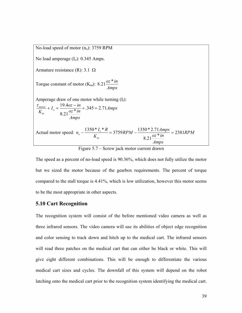
39
No-load speed of motor (no): 3759 RPM No load amperage (Io): 0.345 Amps. Armature resistance (R): 3.1 Ω
Torque constant of motor (Km): Amps
inoz *21.8
Amperage draw of one motor while turning (Il):
Amps
AmpsinozinozI
K om
motor 71.2345.*21.8
4.19=+
−=+
τ
Actual motor speed: RPM
AmpsinozAmpsRPM
KRIn
mo 2381*21.8
71.2*13503759**1350 1 =−=−
Figure 5.7 – Screw jack motor current drawn The speed as a percent of no-load speed is 90.36%, which does not fully utilize the motor
but we sized the motor because of the gearbox requirements. The percent of torque
compared to the stall torque is 4.41%, which is low utilization, however this motor seems
to be the most appropriate in other aspects.
5.10 Cart Recognition
The recognition system will consist of the before mentioned video camera as well as
three infrared sensors. The video camera will use its abilities of object edge recognition
and color sensing to track down and hitch up to the medical cart. The infrared sensors
will read three patches on the medical cart that can either be black or white. This will
give eight different combinations. This will be enough to differentiate the various
medical cart sizes and cycles. The downfall of this system will depend on the robot
latching onto the medical cart prior to the recognition system identifying the medical cart.

40
This will not be a concern for the most part however if the robot has to sort a lot of
medical carts to match two for the same cycle, it will become a concern.
5.11 Overall design/Analysis Conclusion
The overall concept for our robot is a four-wheel design. The front wheels will drive the
medical cart while the back wheels will allow motion in any direction. The turning will
be accomplished by the speed differentiation in the drive wheels. The medical cart will be
lifted by the cubic screw jack. This design can be seen in figure 5.8 below.
Figure 5.8 – Overall Design of Robot

41
6.0 Future Plans
At this point, the team has completed the first six steps required to finish the project. The
team is ready to start the assembly of chosen components and then begin testing the
robot. Changes are expected on the robot housing and on components used. This is due
to future changes on medical cart requirements for safety, motor, and battery sizes.
The team will start performing tests on the robot to acquire knowledge of the problems
that can come up and check for the best way of task completion. This can be done and
learned by:
• Taking the needed measurements by completing tasks one after the other.
• Comparing the team results with the manufacturer component data, so the team
will be able to validate their experiments.
• Software simulation results.
The experimentation will prove that the concept will work and will act as a starting point
for improvement from future teams. The team is going to use AutoDesk Inventor for
mechanical design and C programming for microcontroller design.
6.1 Experimentation
Several experiments must be done to the robot. First, the team must validate that the
performance objectives and specifications have been met. Then, the team will build a
specification table to show the relationship between space, safety, working time and
charging time.
In order for the team to validate the performance objectives and specifications, the speed,
power, torque, and pulling force of the robot will need to be determined. The team will
also need to find the efficiency of the robot. This will be done by continuous testing on

42
various combinations of robot-required tasks, along with precision, power management,
and communication and timing performance.
6.2 Schedule A schedule has been developed for the spring quarter that will keep the team on track to
finish the project on time. The schedule, shown below, has been designed to give the
team an idea of which activities it should be working on and when they should be
completed rather then to describe the day-to-day work of the team.
March April May Task Name 3/12 3/19 3/26 4/2 4/9 4/16 4/23 4/30 5/7 5/14Delivery of components Assembly of Robot Develop Software Testing Program in Microcontroller Test each component with microcontroller Test tasks Test final design Final report Final presentation Critical design review
Figure 6.1 – Spring Quarter Schedule 6.3 Budget The team’s budget is $10,000 provided by Getinge. This money is to be used for building
and testing of the robot. According to the Bill of Materials, the amount spent is less than
$5000. This is a good projection that the entire system can be manufactured for under
$10,000.

43
7.0 Conclusion
The senior design team has completed the first six design processes this quarter. These
include the needs assessment, project objectives, project specifications, concept
development, feasibility assessment, the analysis and synthesis of design and the
preliminary design documents.
The robot designed is the first step toward a working robot. The present design is a proof
of concept, which in the future can be used to take the robot to market. The goal of the
team is to develop, fabricate, and test a robot capable of loading and unloading a washing
machine in a variety of locations.
The team developed four concepts and assessed their feasibility. The concepts include
different sizes, attachment methodology and communication. Although each concept
compared well with the baseline design, the team decided to proceed with the specified
design discussed. This decision was based upon the results of the feasibility analysis, the
constraints, and the company’s requirements. The team will justify the components used
upon testing the robot.
An analysis of several aspects of the robot was completed. A variety of calculations were
done to determine the pulling strength due to frictional effects and weight. Two flow
charts were developed showing the robot’s steps on every move and communication.
Finally, an analysis was done to select the microcontroller that will be used to control the
movements of the robot.
By the end of the spring quarter, the team will have fabricated a robot capable of
completing the tasks required. The team will conduct several experiments designed to

44
analyze the performance of the robot. The experimental results will also be used to
validate the software for future use.

45
References: Product Specification: Model 2040 Automated Loading and Unloading System, Specification Number: 360246, Getinge Sourcing. LLC. Hazard Analysis, Series 7800/7900 Health Care Washers, Specification Number: 360231, Getinge Sourcing. LLC. Design Control Procedure, 8/04/03, QSP # 110, Rev. E, Getinge Sourcing. LLC. Data and Specifications, Model 7800 Series Floor Loading Cart Washer, Getinge USA. http://www.motioncontrol.com http://www.maxonmotorusa.com/ http://www.micromo.com/ http://www.superdroidrobots.com/trekker_drive.htm http://www.oopic.com http://www.robotcombat.com/marketplace_motors.html http://www.lynxmotion.com http://www.robotics.com http://www.mobilerobots.com http://www.activrobots.com/ http://www.engr.iupui.edu/me/courses/fproject.shtml http://www.atmel.com/dyn/resources/prod_documents/doc1253.pdf http://microcontrollershop.ucpros.com/product_info.php?products_id=154 http://www.keil.com/mcb517/ http://eet.etec.wwu.edu/CPU12/PODInstrs.pdf http://www.post-gazette.com/businessnews/20011025aethon1025bnp2.asp http://www.irobot.com

46
http://www.aai.ca/robots/index.html http://www.robotbooks.com http://www.medtronic.com/semi/products/microcontrollers.html http://microcontroller.com/default.asp http://www.samsung.com/Products/Semiconductor/common/product_list.jsp?family_cd=LSI060101 http://www.robotstorehk.com/sensor.html http://www.aethon.com/ http://www.angelusresearch.com

47
List of Appendices
Appendix A: Software Flowcharts Appendix B: Sample Storage Layout Appendix C: Circuit Block Diagram Appendix D: Bill of Materials Appendix E: Order Forms Appendix F: Design Drawings Appendix G: Technical Drawings Appendix H: Calculations

Appendix B: Sample Storage Layout

Appendix A: Software Flowcharts

Appendix C: Circuit Block Diagram

Appendix D: Bill of Materials

Appendix E: Order Forms

Appendix F Design Drawings

Appendix G: Technical Drawings

Appendix H: Calculations

Apply Charge
battery full
standby
Yes
No
Charge
5 min tillfinish wash
charge to cart
Yes
No
Charging Load Side
Charge
1 min tillfinish wash
charge to washer
Yes
No
Unload Side

follow parking line
obstacelaviodance
follow line toparking area #2
at parking area #1
Cart Available
Hook to Cart
Charger to Parking
Yes
No
Search for Carts
Yes
No
obstacelaviodance
at parking area #2
Cart Available
Yes
No
Search for Carts
No
Hook to Cart
Yes
Wait
Battery LowNo
Yes
Charge
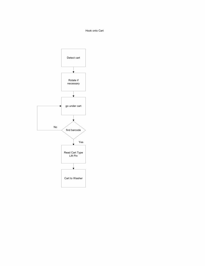
Hook onto Cart
Detect cart
Rotate ifnecessary
go under cart
find barcode
Yes
No
Read Cart TypeLift Pin
Cart to Washer

go around left
obstacle
obstacle
obstacle avoidance
Yes
No
stop wait3 seconds
Yes
left clear right clearNo
continue
No
go around right
Yes
call for help
No
Yes

follow parking line
obstacelaviodance
backup
at washer
end of washer
Remove Pin
parking to washer
Yes
No
enter washer
Yes
cart #1 Cart #2possible
No
Get cart
No
start washer cycle
Yes
return tocharging area
No
Yes

check area 2
empty
wait
check area 1
Yes
battery low
No
Yes
No
empty
battery low
Yes
charge
No
return

Washing Machine
charging area
Parking AreaSMALL CARTS
Parking AreaLARGE CARTS