Embed Size (px)
Citation preview
Automated Laboratory Particle Counter ALPC 9000 series
Operating and Maintenance Instructions
English (translation of original instructions)
Document No.: 3601005
ALPC 9000 series Trademarks
Trademarks
The trademarks of other companies are exclusively used for the products of those companies.
Copyright © 2011 HYDAC FILTER SYSTEMS GMBH all rights reserved
All rights reserved. This manual may not be reproduced in part or whole without the express written consent of HYDAC Filter Systems GmbH. Contraventions are liable to compensation.
Exclusion of Liability
We have made every endeavour to ensure the accuracy of the contents of this document. However, errors cannot be ruled out. Consequently, we accept no liability for such errors as may exist nor for any damage or loss whatsoever which may arise as a result of such errors. The content of the manual is checked regularly. Any corrections required will be incorporated in future editions. We welcome any suggestions for improvements.
All details are subject to technical modifications.
Technical specifications are subject to change without notice.
HYDAC FILTER SYSTEMS GMBHPostfach 12 5166273 Sulzbach / Saar
Germany
Documentation Representative
Mr. Günter Harge
c/o HYDAC International GMBH, Industriegebiet, 66280 Sulzbach / Saar
Telephone: ++49 (0)6897 509 1511
Telefax: ++49 (0)6897 509 1394
E-mail: [email protected]
HYDAC FILTER SYSTEMS GMBH en Page 2 / 68
BEWA ALPC9000 3601005 en 2011-04-07.doc 2011-04-06
ALPC 9000 series Content
HYDAC FILTER SYSTEMS GMBH en Page 3 / 68
BEWA ALPC9000 3601005 en 2011-04-07.doc 2011-04-06
Content
Trademarks ...............................................................................................................2
Documentation Representative...............................................................................2
Content......................................................................................................................3
Preface ......................................................................................................................5
Technical Support...................................................................................................6 Modifications to the Product ...................................................................................6 Warranty .................................................................................................................6 Using the Documentation .......................................................................................7
Safety information....................................................................................................8
Obligations and Liability..........................................................................................8 Explanation of Symbols and Warnings, etc. ...........................................................9 Proper/Designated Use ..........................................................................................9 Improper Use ........................................................................................................10 Procedure in an Emergency .................................................................................10 Maintenance, Servicing and Troubleshooting.......................................................10 Structural Modifications to the ALPC ....................................................................11 Electrical Hazards.................................................................................................11 Training and Instruction of Personnel ...................................................................12
Transporting the ALPC ..........................................................................................13
Storing the ALPC....................................................................................................13
Checking the Scope of Delivery............................................................................14
Description of the ALPC ........................................................................................15
Restrictions pertaining to use ...............................................................................16
Setting up the ALPC...............................................................................................16
ALPC dimensions / work areas .........................................................................17
ALPC components .................................................................................................18
Components of basic unit ALPC 9000-1...............................................................20 Safety door to the analysis room.......................................................................21 Mains box..........................................................................................................22 Electrical control................................................................................................23 Maintenance unit...............................................................................................24 Suction hose with suction screen - Flushing fluid tank - ...................................25 Return hose - Return tank.................................................................................25
Extension unit ALPC 9000-2.................................................................................26 Protective housing with safety door ..................................................................27 Emergency stop (S0) ........................................................................................28 Sustain vacuum manually (S5) .........................................................................28 Robot.................................................................................................................29 Robot controller.................................................................................................30

ALPC 9000 series Content
HYDAC FILTER SYSTEMS GMBH en Page 4 / 68
BEWA ALPC9000 3601005 en 2011-04-07.doc 2011-04-06
Sample shaker ..................................................................................................32
Prior to switching the unit on................................................................................33
Switching on the ALPC..........................................................................................34
Preparing sample bottles for analysis..................................................................35
Adjust and secure the sample pallet in ALPC ...................................................37 Change sample pallets 100 / 100 / 30 (optional)...............................................38
Perform analysis.....................................................................................................40
Analysis and flushing process ..............................................................................41
Switching off the ALPC..........................................................................................45
Performing Maintenance........................................................................................46
Maintenance intervals / plan .................................................................................46 Carry out a lamp test on the mains box ................................................................48 Check the sealing ring on the pressure dome ......................................................48 Clean the suction screen on the flushing fluid tank suction hose. ........................48 Cleaning the oil pan ..............................................................................................49 Check / replace hoses ..........................................................................................50 Maintaining the maintenance unit .........................................................................51
Replacing the silencer.......................................................................................51 Changing the filter insert ...................................................................................52 Drain condensate ..............................................................................................53
Cleaning the sealing disk......................................................................................54 Change the sealing disk on the vacuum hand......................................................55 Replacing the vacuum hoses on the robot ...........................................................56
Dismantling the rear wall on the protective housing..........................................57 Replace the vacuum hoses...............................................................................58 Changing the silencer on the vacuum generator ..............................................58 Mounting the rear wall of the protective housing...............................................59
Pneumatic / hydraulic diagram .............................................................................60
Spare Parts List ......................................................................................................62
Spare Parts...........................................................................................................62
Disposing of the ALPC...........................................................................................62
Calibrating the ALPC..............................................................................................62
Customer Service...................................................................................................63
Germany ...............................................................................................................63 USA ......................................................................................................................63 Australia................................................................................................................63 Brazil .....................................................................................................................64
Technical data ........................................................................................................65
Model Code .............................................................................................................66
ALPC 9000 series Preface
Preface
For you, as the owner of a product manufactured by us, we have produced this manual, comprising the most important instructions for its operation and maintenance.
It is intended to help you become acquainted with the ins and outs of the product and use it properly.
You should keep it in the vicinity of the product so it is always at your fingertips.
Sometimes the information contained in the documentation cannot always keep up with changes made to the product as we attach considerable importance to keeping our products cutting-edge.Consequently, there might be deviations in technical details, illustrations and dimensions.
If you discover errors while reading the documentation or have suggestions or other useful information, please don’t hesitate to contact us:
HYDAC FILTER SYSTEMS GMBHTechnische DokumentationPostfach 12 5166273 Sulzbach / Saar
Germany
We look forward to receiving your input.
Our motto: “Putting experience into practice”
HYDAC FILTER SYSTEMS GMBH en Page 5 / 68
BEWA ALPC9000 3601005 en 2011-04-07.doc 2011-04-06
ALPC 9000 series Preface
HYDAC FILTER SYSTEMS GMBH en Page 6 / 68
BEWA ALPC9000 3601005 en 2011-04-07.doc 2011-04-06
Technical Support If you have any questions, suggestions, or encounter any problems of a technical nature, please don't hesitate to contact us. When contacting us, please always include the model/type designation and article no. of the product:
Fax: +49 (0) 6897 / 509 - 846
E-mail: [email protected]
Modifications to the Product We would like to point out that changes to the product (e.g. purchasing options, etc.) may result in the information in the operating instructions no longer being completely accurate or sufficient.
When making modifications or performing repair work to components affecting the safety of the product, the product may not be put back into operation until it has been examined and released by a HYDAC representative.
Please notify us immediately of any modifications made to the product whether by you or a third party.
Warranty For the warranty provided by us, please refer to the General Terms of Sale and Delivery of HYDAC FILTER SYSTEMS GmbH.
Refer to these at www.hydac.com ð General terms and conditions.
ALPC 9000 series Preface
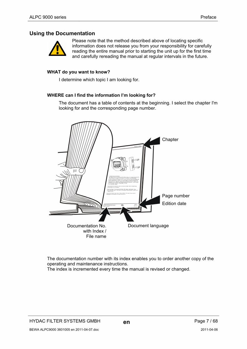
Using the Documentation
Please note that the method described above of locating specific information does not release you from your responsibility for carefully reading the entire manual prior to starting the unit up for the first time and carefully rereading the manual at regular intervals in the future.
WHAT do you want to know?
I determine which topic I am looking for.
WHERE can I find the information I’m looking for?
The document has a table of contents at the beginning. I select the chapter I'm looking for and the corresponding page number.
deHYDAC Filtertechnik GmbHBeWa 123456a de
Seite x
Produkt / Kapitel
200x-xx-xx
Chapter
Page number
Edition date
Document language Documentation No.with Index /
File name
The documentation number with its index enables you to order another copy of the operating and maintenance instructions. The index is incremented every time the manual is revised or changed.
HYDAC FILTER SYSTEMS GMBH en Page 7 / 68
BEWA ALPC9000 3601005 en 2011-04-07.doc 2011-04-06
ALPC 9000 series Safety information
HYDAC FILTER SYSTEMS GMBH en Page 8 / 68
BEWA ALPC9000 3601005 en 2011-04-07.doc 2011-04-06
Safety information
These operating instructions contain the key instructions for properly and safely operating the ALPC.
Obligations and Liability
The basic prerequisite for the safe and proper handling and operation of the ALPC is knowledge of the safety instructions and warnings.
These operating instructions in general, and the safety precautions in particular, are to be adhered by all those who work with the ALPC.
Adherence is to be maintained to pertinent accident prevention regulations applicable at the site where the product is used.
The ALPC has been designed and constructed in accordance with the current state of the art and recognized safety regulations. Nevertheless, hazard may be posed to the life and limb of the individual using the product or to third parties.
The ALPC is only to be used as follows:
Solely for its designated use
only when in a safe, perfect condition
Immediately remedy any malfunctions that might impair safety.
Always keep the operating and maintenance instructions near the measurement device.
As a supplement to the operating instructions, the general as well as the local regulations regarding accident prevention and environmental protection should be made available and observed.
Ensure that all information relating to safety and potential hazards of the ALPC are kept in a legible condition. Replace them if necessary.
Check the hoses and connectors for leaks on a daily basis.
ALPC 9000 series Safety information
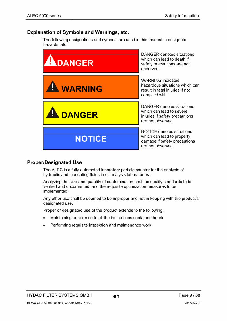
Explanation of Symbols and Warnings, etc.
The following designations and symbols are used in this manual to designate hazards, etc.:
DANGER DANGER denotes situations which can lead to death if safety precautions are not observed.
WARNING WARNING indicates hazardous situations which can result in fatal injuries if not complied with.
DANGER DANGER denotes situations which can lead to severe injuries if safety precautions are not observed.
NOTICE NOTICE denotes situations which can lead to property damage if safety precautions are not observed.
Proper/Designated Use
The ALPC is a fully automated laboratory particle counter for the analysis of hydraulic and lubricating fluids in oil analysis laboratories.
Analyzing the size and quantity of contamination enables quality standards to be verified and documented, and the requisite optimization measures to be implemented.
Any other use shall be deemed to be improper and not in keeping with the product's designated use.
Proper or designated use of the product extends to the following:
Maintaining adherence to all the instructions contained herein.
Performing requisite inspection and maintenance work.
HYDAC FILTER SYSTEMS GMBH en Page 9 / 68
BEWA ALPC9000 3601005 en 2011-04-07.doc 2011-04-06
ALPC 9000 series Safety information
Improper Use
Any use deviating from the proper/designated use described above is prohibited.
Improper use may result in hazard to life and limb.
Example of improper use:
Sampling of fluid with a flash point of < 55°C
Flushing with fluid with a flash point of < 55°C
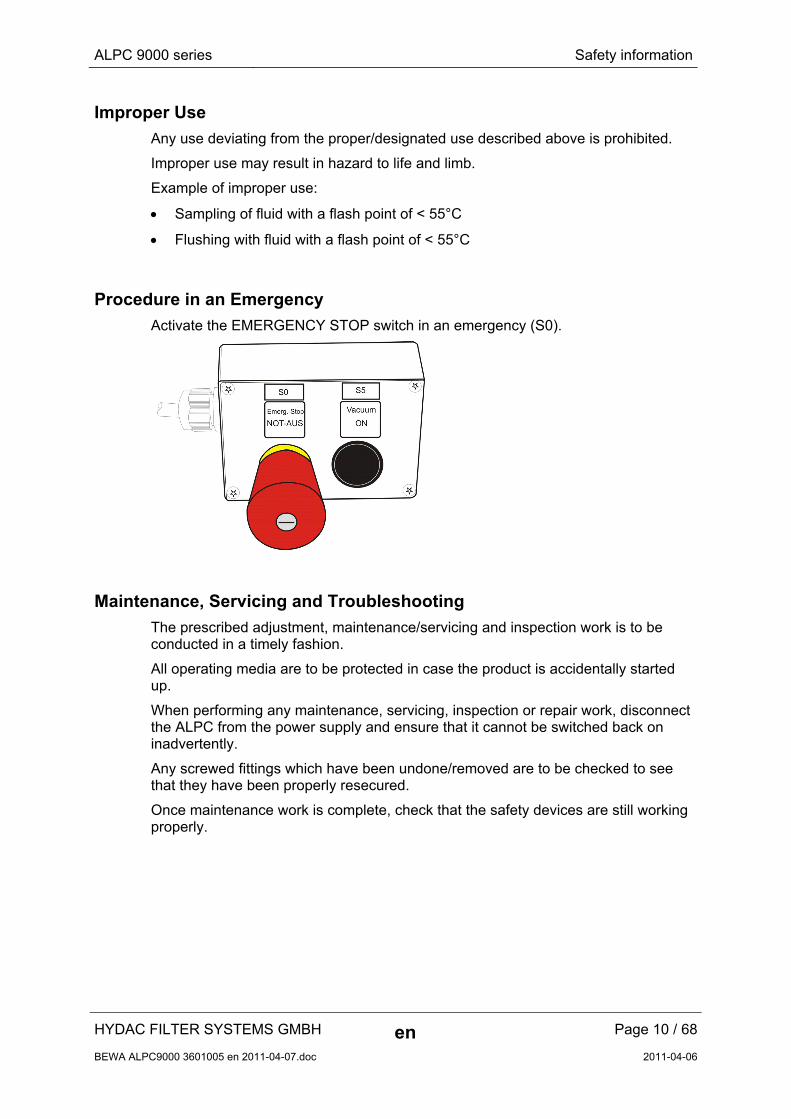
Procedure in an Emergency
Activate the EMERGENCY STOP switch in an emergency (S0).
Maintenance, Servicing and Troubleshooting
The prescribed adjustment, maintenance/servicing and inspection work is to be conducted in a timely fashion.
All operating media are to be protected in case the product is accidentally started up.
When performing any maintenance, servicing, inspection or repair work, disconnect the ALPC from the power supply and ensure that it cannot be switched back on inadvertently.
Any screwed fittings which have been undone/removed are to be checked to see that they have been properly resecured.
Once maintenance work is complete, check that the safety devices are still working properly.
HYDAC FILTER SYSTEMS GMBH en Page 10 / 68
BEWA ALPC9000 3601005 en 2011-04-07.doc 2011-04-06
ALPC 9000 series Safety information
Structural Modifications to the ALPC
Do not make any modifications to the ALPC.
Any modifications require written permission from HYDAC FILTER SYSTEMS GMBH.
Immediately replace any parts which are not in perfect condition. Use only original spare parts (OEM).
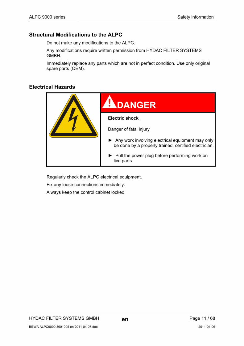
Electrical Hazards
DANGER Electric shock
Danger of fatal injury
► Any work involving electrical equipment may only
be done by a properly trained, certified electrician.
► Pull the power plug before performing work on live parts.
Regularly check the ALPC electrical equipment.
Fix any loose connections immediately.
Always keep the control cabinet locked.
HYDAC FILTER SYSTEMS GMBH en Page 11 / 68
BEWA ALPC9000 3601005 en 2011-04-07.doc 2011-04-06
ALPC 9000 series Safety information
HYDAC FILTER SYSTEMS GMBH en Page 12 / 68
BEWA ALPC9000 3601005 en 2011-04-07.doc 2011-04-06
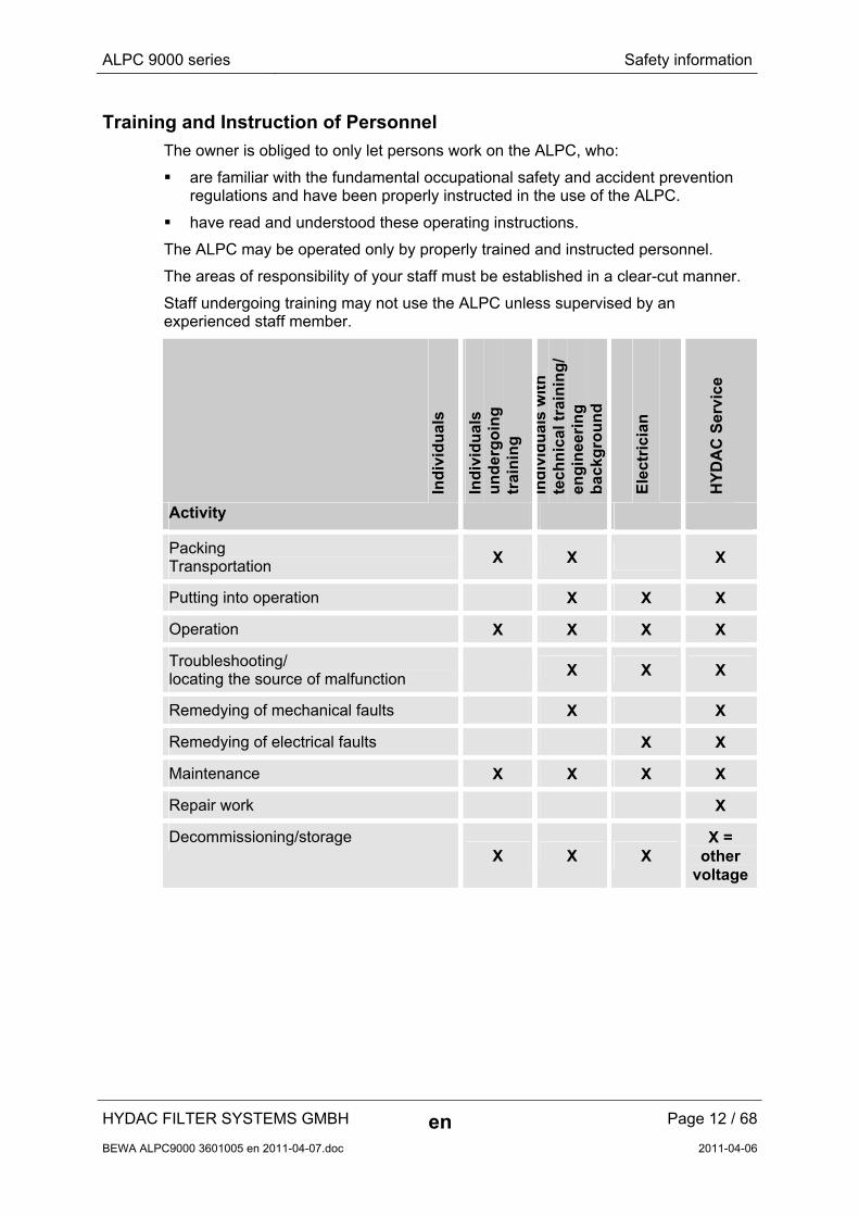
Training and Instruction of Personnel
The owner is obliged to only let persons work on the ALPC, who:
are familiar with the fundamental occupational safety and accident prevention regulations and have been properly instructed in the use of the ALPC.
have read and understood these operating instructions.
The ALPC may be operated only by properly trained and instructed personnel.
The areas of responsibility of your staff must be established in a clear-cut manner.
Staff undergoing training may not use the ALPC unless supervised by an experienced staff member.
Ind
ivid
ual
s
Ind
ivid
ual
s u
nd
erg
oin
g
trai
nin
g
Ind
ivid
ual
s w
ith
te
chn
ical
tra
inin
g/
eng
inee
rin
g
bac
kgro
un
d
Ele
ctri
cian
HY
DA
C S
ervi
ce
Activity
Packing Transportation X X X
Putting into operation X X X
Operation X X X X
Troubleshooting/ locating the source of malfunction
X X X
Remedying of mechanical faults X X
Remedying of electrical faults X X
Maintenance X X X X
Repair work X
Decommissioning/storage X X X
X = other
voltage
ALPC 9000 series Transporting the ALPC
HYDAC FILTER SYSTEMS GMBH en Page 13 / 68
BEWA ALPC9000 3601005 en 2011-04-07.doc 2011-04-06
Transporting the ALPC
Dismantle the ALPC completely into its individual components for transport.
Storing the ALPC
Pull power plug. Coil up the power cable and fix it to the ALPC.
Drain the reservoirs and filters of the ALPC completely before putting it into extended storage.
Store the ALPC in a clean, dry room, with the following conditions:
Storage temperature: 0 … 70°C / 32 … 158°F
Humidity: Maximum 90%, non-condensing
Air: dust-free, no salty air, not in the vicinity of oxidizing substances (flash rust, rust bloom)
ALPC 9000 series Checking the Scope of Delivery
HYDAC FILTER SYSTEMS GMBH en Page 14 / 68
BEWA ALPC9000 3601005 en 2011-04-07.doc 2011-04-06
Checking the Scope of Delivery
The ALPC is handed over ready for operation.
The following items are supplied:
Qty. Description
1 ALPC 9000 series
1 Operating and maintenance instructions
1 ALPCDesk Software Manual
1 Documentation on the robot
1 Calibration certificate
1 EC declaration of conformity
1 Support CD
1 CD with driver to the PC
ALPC 9000 series Description of the ALPC
HYDAC FILTER SYSTEMS GMBH en Page 15 / 68
BEWA ALPC9000 3601005 en 2011-04-07.doc 2011-04-06
Description of the ALPC
The ALPC is a fully automated laboratory particle counter for the analysis of hydraulic and lubricating fluids in oil analysis laboratories.
A sample pallet with samples is positioned on a sample shaker next to the particle counter; each sample is individually added to the particle counter.
The sample shaker serves to keep the samples homogenized. Prepare the samples before adding them into the sample pallet.
You can file an ID number for each sample as a reference in the ALPCDesk software.
Initiated by pressing a key on the PC keyboard or by clicking on the mouse, the particle counter carries out an automatic analysis of the sample.
The analsysis of a sample is only accepted if the measurement values of two subsequent sample runs lie within a predefined tolerance.
The analysis of a sample is rejected if it does not lie within a predefined tolerance after five sample runs. The number of maximum sample runs can be defined in the ALPCDesk software.
The ALPC flushes the sensor manually after the key is pressed, or automatically after each sampling procedure. The flushing fluid is analysed during the flushing process. The flushing process can be controlled according to the level of contamination or the time.
The recorded data (particle numbers and ISO codes) are stored on the hard drive. You can call up these measurement values again at any time using the ALPCDESK software.
ALPC 9000 series Setting up the ALPC
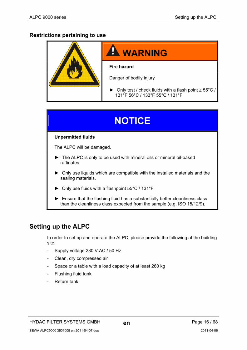
Restrictions pertaining to use
WARNING Fire hazard
Danger of bodily injury
► Only test / check fluids with a flash point 55°C /
131°F 56°C / 133°F 55°C / 131°F
NOTICE
Unpermitted fluids
The ALPC will be damaged.
► The ALPC is only to be used with mineral oils or mineral oil-based raffinates.
► Only use liquids which are compatible with the installed materials and the sealing materials.
► Only use fluids with a flashpoint 55°C / 131°F
► Ensure that the flushing fluid has a substantially better cleanliness class than the cleanliness class expected from the sample (e.g. ISO 15/12/9).
Setting up the ALPC
In order to set up and operate the ALPC, please provide the following at the building site:
- Supply voltage 230 V AC / 50 Hz
- Clean, dry compressed air
- Space or a table with a load capacity of at least 260 kg
- Flushing fluid tank
- Return tank
HYDAC FILTER SYSTEMS GMBH en Page 16 / 68
BEWA ALPC9000 3601005 en 2011-04-07.doc 2011-04-06
ALPC 9000 series Setting up the ALPC
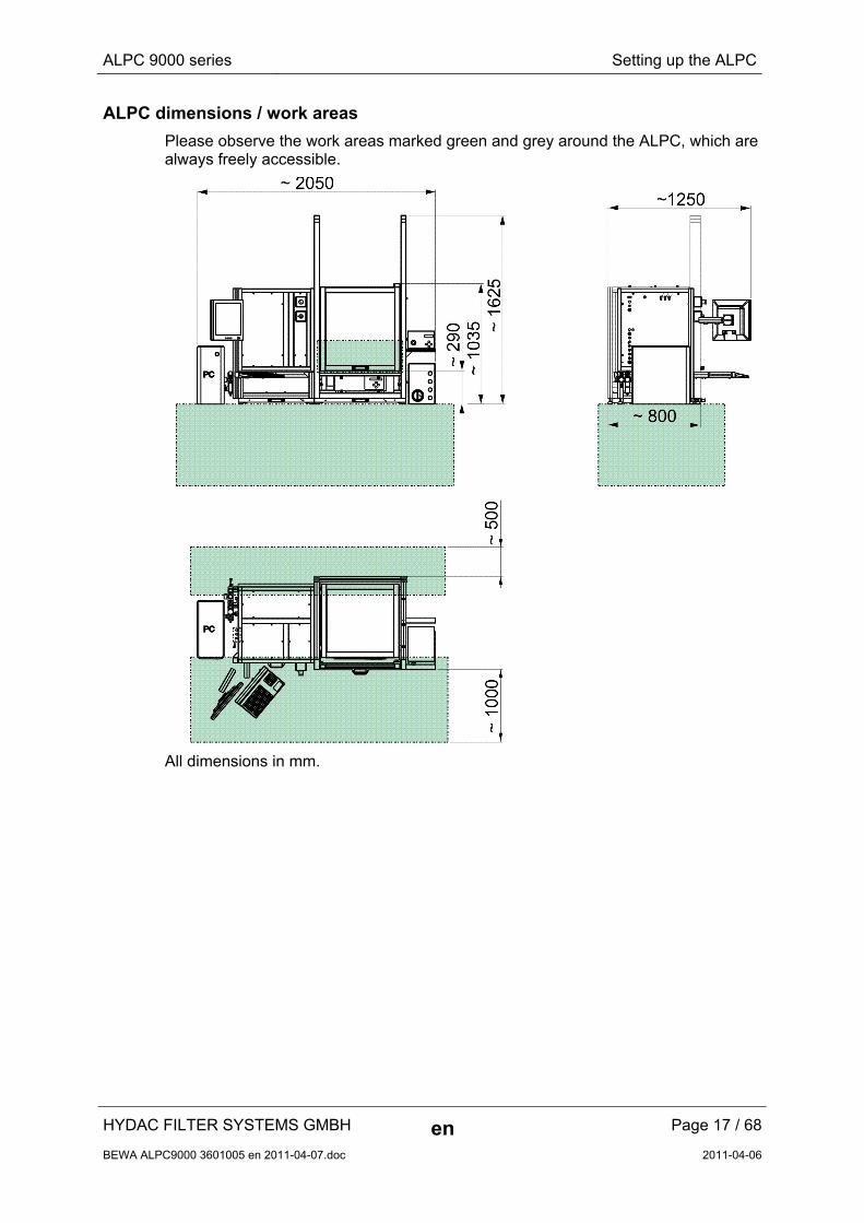
ALPC dimensions / work areas
Please observe the work areas marked green and grey around the ALPC, which are always freely accessible.
All dimensions in mm.
HYDAC FILTER SYSTEMS GMBH en Page 17 / 68
BEWA ALPC9000 3601005 en 2011-04-07.doc 2011-04-06
ALPC 9000 series ALPC components
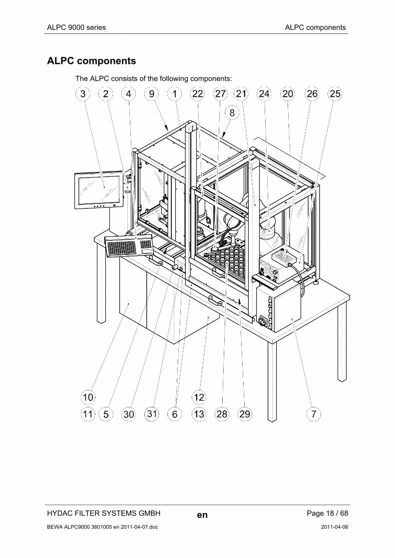
ALPC components
The ALPC consists of the following components:
HYDAC FILTER SYSTEMS GMBH en Page 18 / 68
BEWA ALPC9000 3601005 en 2011-04-07.doc 2011-04-06
ALPC 9000 series ALPC components
HYDAC FILTER SYSTEMS GMBH en Page 19 / 68
BEWA ALPC9000 3601005 en 2011-04-07.doc 2011-04-06
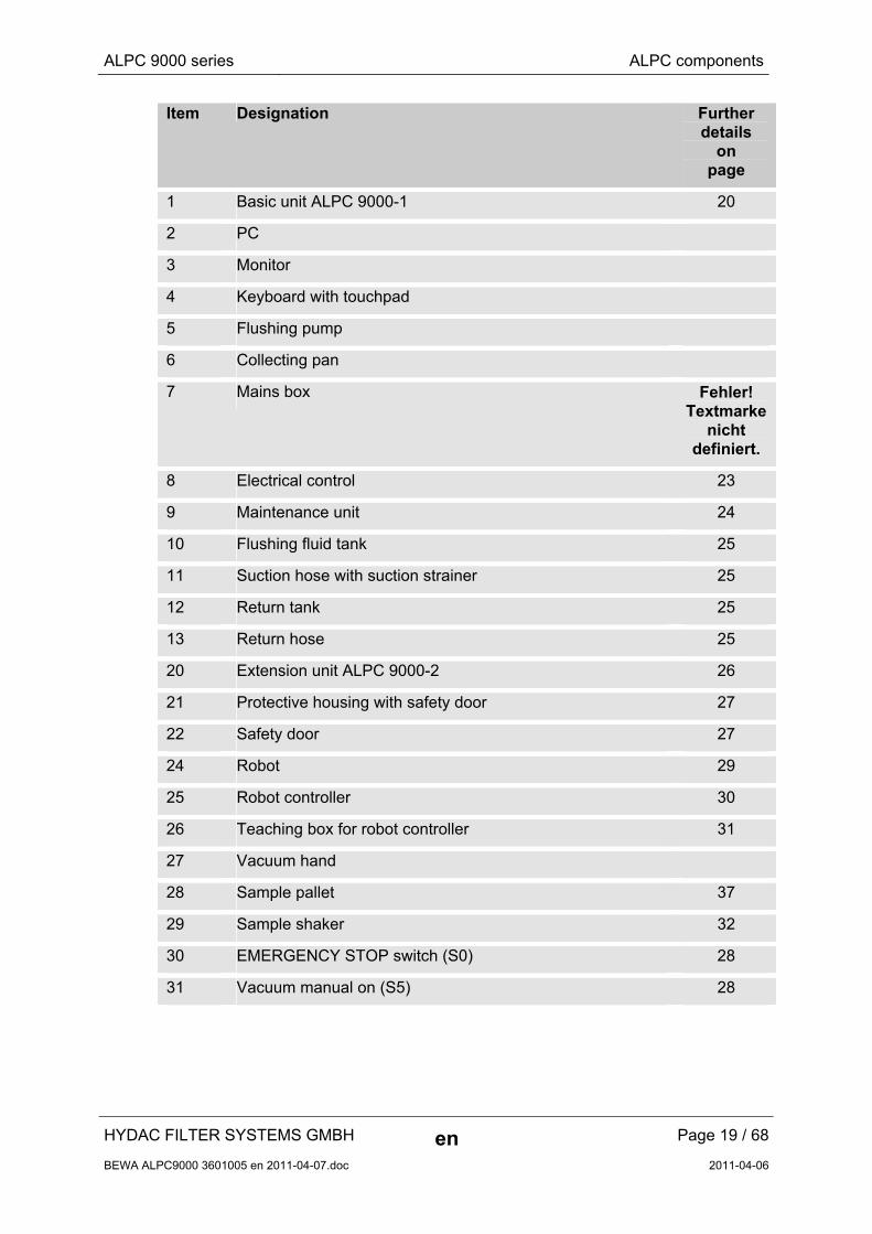
Item Designation Further details
on page
1 Basic unit ALPC 9000-1 20
2 PC
3 Monitor
4 Keyboard with touchpad
5 Flushing pump
6 Collecting pan
7 Mains box Fehler! Textmarke
nicht definiert.
8 Electrical control 23
9 Maintenance unit 24
10 Flushing fluid tank 25
11 Suction hose with suction strainer 25
12 Return tank 25
13 Return hose 25
20 Extension unit ALPC 9000-2 26
21 Protective housing with safety door 27
22 Safety door 27
24 Robot 29
25 Robot controller 30
26 Teaching box for robot controller 31
27 Vacuum hand
28 Sample pallet 37
29 Sample shaker 32
30 EMERGENCY STOP switch (S0) 28
31 Vacuum manual on (S5) 28
ALPC 9000 series ALPC components
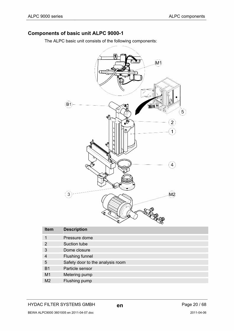
Components of basic unit ALPC 9000-1
The ALPC basic unit consists of the following components:
Item Description
1 Pressure dome
2 Suction tube
3 Dome closure
4 Flushing funnel
5 Safety door to the analysis room
B1 Particle sensor
M1 Metering pump
M2 Flushing pump
HYDAC FILTER SYSTEMS GMBH en Page 20 / 68
BEWA ALPC9000 3601005 en 2011-04-07.doc 2011-04-06
ALPC 9000 series ALPC components
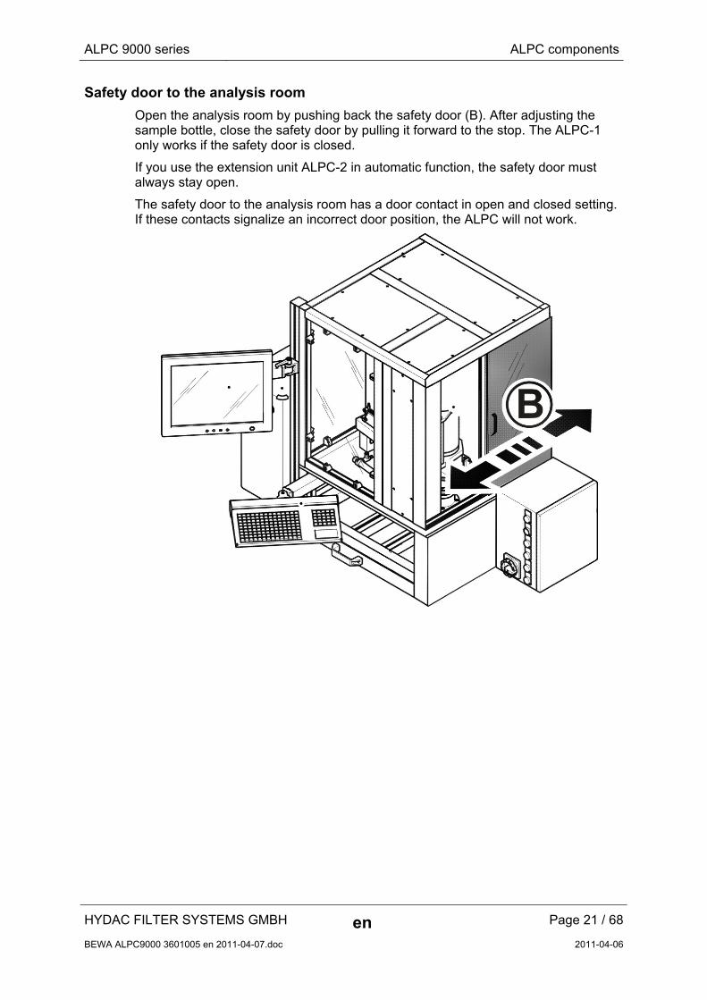
Safety door to the analysis room
Open the analysis room by pushing back the safety door (B). After adjusting the sample bottle, close the safety door by pulling it forward to the stop. The ALPC-1 only works if the safety door is closed.
If you use the extension unit ALPC-2 in automatic function, the safety door must always stay open.
The safety door to the analysis room has a door contact in open and closed setting. If these contacts signalize an incorrect door position, the ALPC will not work.
HYDAC FILTER SYSTEMS GMBH en Page 21 / 68
BEWA ALPC9000 3601005 en 2011-04-07.doc 2011-04-06
ALPC 9000 series ALPC components
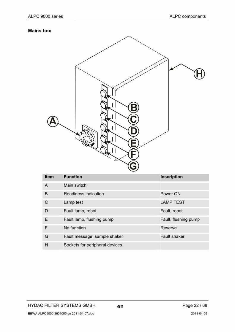
Mains box
Item Function Inscription
A Main switch
B Readiness indication Power ON
C Lamp test LAMP TEST
D Fault lamp, robot Fault, robot
E Fault lamp, flushing pump Fault, flushing pump
F No function Reserve
G Fault message, sample shaker Fault shaker
H Sockets for peripheral devices
HYDAC FILTER SYSTEMS GMBH en Page 22 / 68
BEWA ALPC9000 3601005 en 2011-04-07.doc 2011-04-06
ALPC 9000 series ALPC components
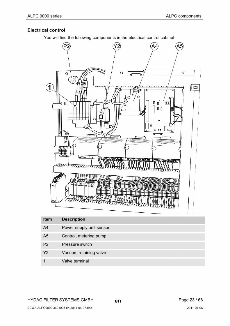
Electrical control
You will find the following components in the electrical control cabinet:
Item Description
A4 Power supply unit sensor
A5 Control, metering pump
P2 Pressure switch
Y2 Vacuum retaining valve
1 Valve terminal
HYDAC FILTER SYSTEMS GMBH en Page 23 / 68
BEWA ALPC9000 3601005 en 2011-04-07.doc 2011-04-06
ALPC 9000 series ALPC components
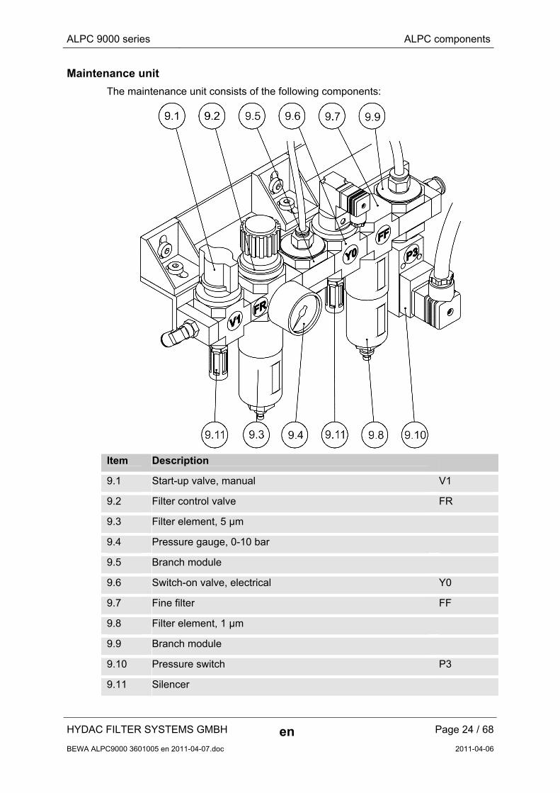
Maintenance unit
The maintenance unit consists of the following components:
Item Description
9.1 Start-up valve, manual V1
9.2 Filter control valve FR
9.3 Filter element, 5 µm
9.4 Pressure gauge, 0-10 bar
9.5 Branch module
9.6 Switch-on valve, electrical Y0
9.7 Fine filter FF
9.8 Filter element, 1 µm
9.9 Branch module
9.10 Pressure switch P3
9.11 Silencer
HYDAC FILTER SYSTEMS GMBH en Page 24 / 68
BEWA ALPC9000 3601005 en 2011-04-07.doc 2011-04-06
ALPC 9000 series ALPC components
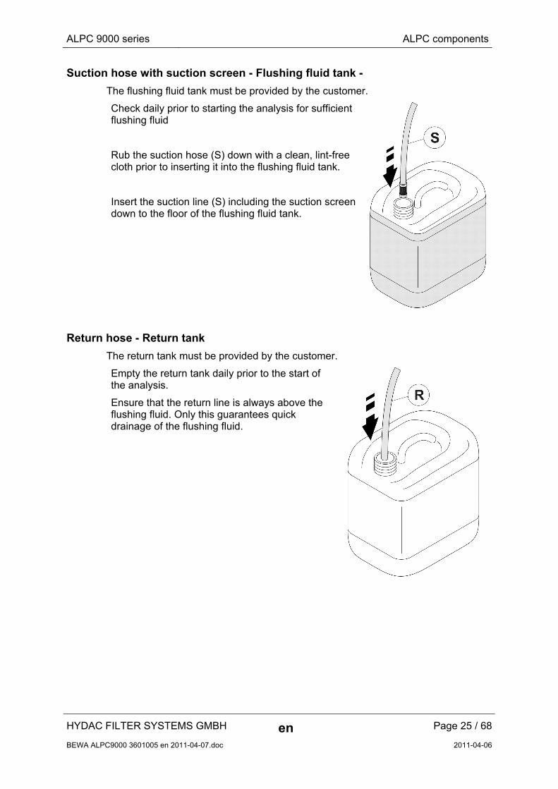
Suction hose with suction screen - Flushing fluid tank -
The flushing fluid tank must be provided by the customer.
Check daily prior to starting the analysis for sufficient flushing fluid
Rub the suction hose (S) down with a clean, lint-free cloth prior to inserting it into the flushing fluid tank.
Insert the suction line (S) including the suction screen down to the floor of the flushing fluid tank.
Return hose - Return tank
The return tank must be provided by the customer.
Empty the return tank daily prior to the start of the analysis.
Ensure that the return line is always above the flushing fluid. Only this guarantees quick drainage of the flushing fluid.
HYDAC FILTER SYSTEMS GMBH en Page 25 / 68
BEWA ALPC9000 3601005 en 2011-04-07.doc 2011-04-06
ALPC 9000 series ALPC components
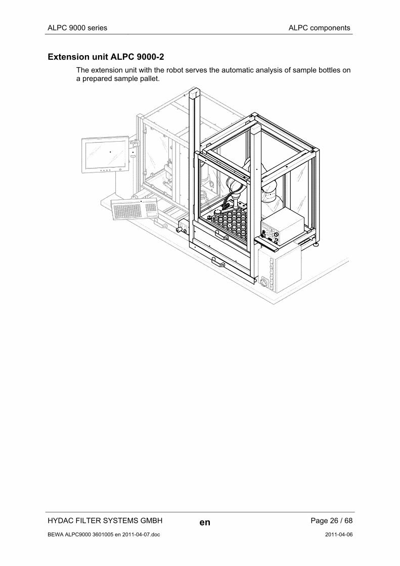
Extension unit ALPC 9000-2
The extension unit with the robot serves the automatic analysis of sample bottles on a prepared sample pallet.
HYDAC FILTER SYSTEMS GMBH en Page 26 / 68
BEWA ALPC9000 3601005 en 2011-04-07.doc 2011-04-06
ALPC 9000 series ALPC components
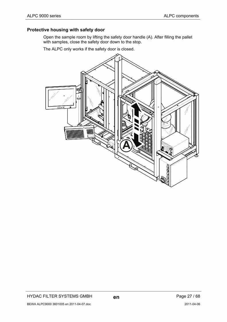
Protective housing with safety door
Open the sample room by lifting the safety door handle (A). After filling the pallet with samples, close the safety door down to the stop.
The ALPC only works if the safety door is closed.
HYDAC FILTER SYSTEMS GMBH en Page 27 / 68
BEWA ALPC9000 3601005 en 2011-04-07.doc 2011-04-06

ALPC 9000 series ALPC components
Emergency stop (S0)
Actuate the Emergency stop switch in hazardous situations.
After actuating the Emergency stop switch, the ALPC is de-energized after the mains box and the compressed air supply is blocked. Any vacuum is interrupted immediately.
Sustain vacuum manually (S5)
On actuating the Emergency stop switch or on opening the safety door manually, the vacuum is interrupted immediately. The means that any sample located on the vacuum hand will drop off.
In order to sustain the vacuum, press the "Vacuum ON" button
HYDAC FILTER SYSTEMS GMBH en Page 28 / 68
BEWA ALPC9000 3601005 en 2011-04-07.doc 2011-04-06
ALPC 9000 series ALPC components
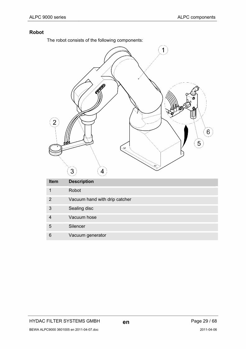
Robot
The robot consists of the following components:
Item Description
1 Robot
2 Vacuum hand with drip catcher
3 Sealing disc
4 Vacuum hose
5 Silencer
6 Vacuum generator
HYDAC FILTER SYSTEMS GMBH en Page 29 / 68
BEWA ALPC9000 3601005 en 2011-04-07.doc 2011-04-06
ALPC 9000 series ALPC components
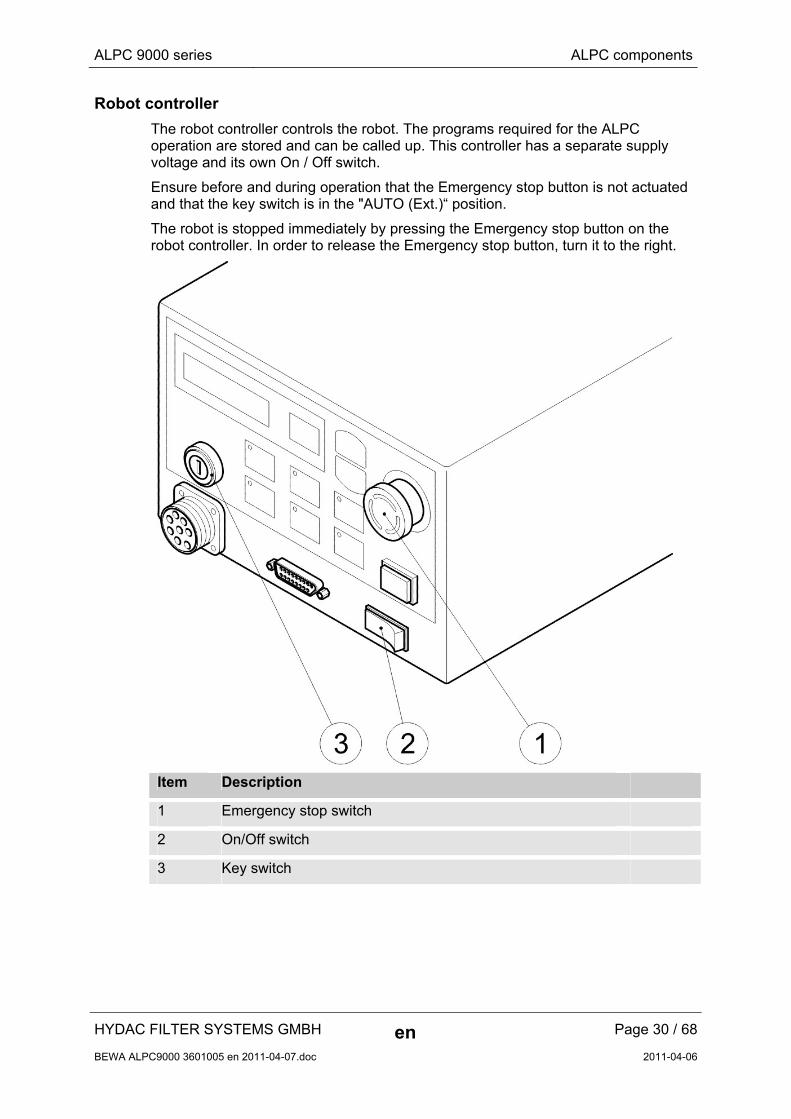
Robot controller
The robot controller controls the robot. The programs required for the ALPC operation are stored and can be called up. This controller has a separate supply voltage and its own On / Off switch.
Ensure before and during operation that the Emergency stop button is not actuated and that the key switch is in the "AUTO (Ext.)“ position.
The robot is stopped immediately by pressing the Emergency stop button on the robot controller. In order to release the Emergency stop button, turn it to the right.
Item Description
1 Emergency stop switch
2 On/Off switch
3 Key switch
HYDAC FILTER SYSTEMS GMBH en Page 30 / 68
BEWA ALPC9000 3601005 en 2011-04-07.doc 2011-04-06
ALPC 9000 series ALPC components
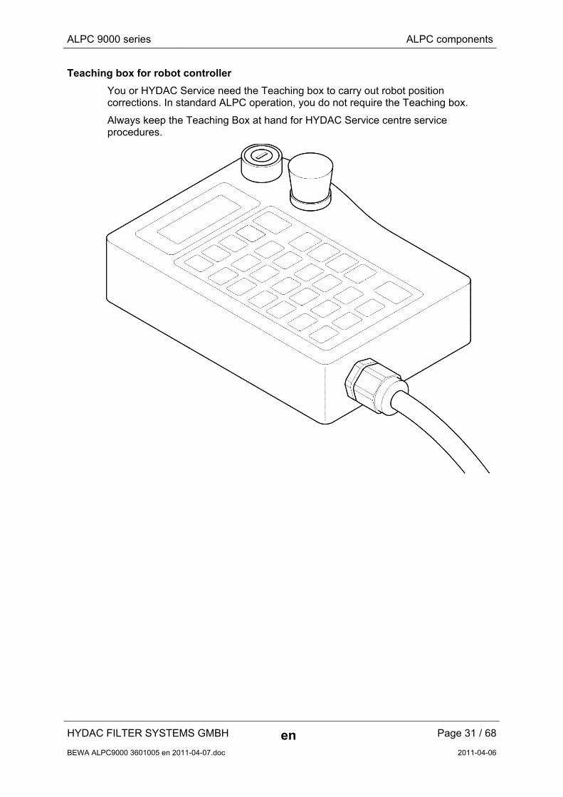
Teaching box for robot controller
You or HYDAC Service need the Teaching box to carry out robot position corrections. In standard ALPC operation, you do not require the Teaching box.
Always keep the Teaching Box at hand for HYDAC Service centre service procedures.
HYDAC FILTER SYSTEMS GMBH en Page 31 / 68
BEWA ALPC9000 3601005 en 2011-04-07.doc 2011-04-06
ALPC 9000 series ALPC components
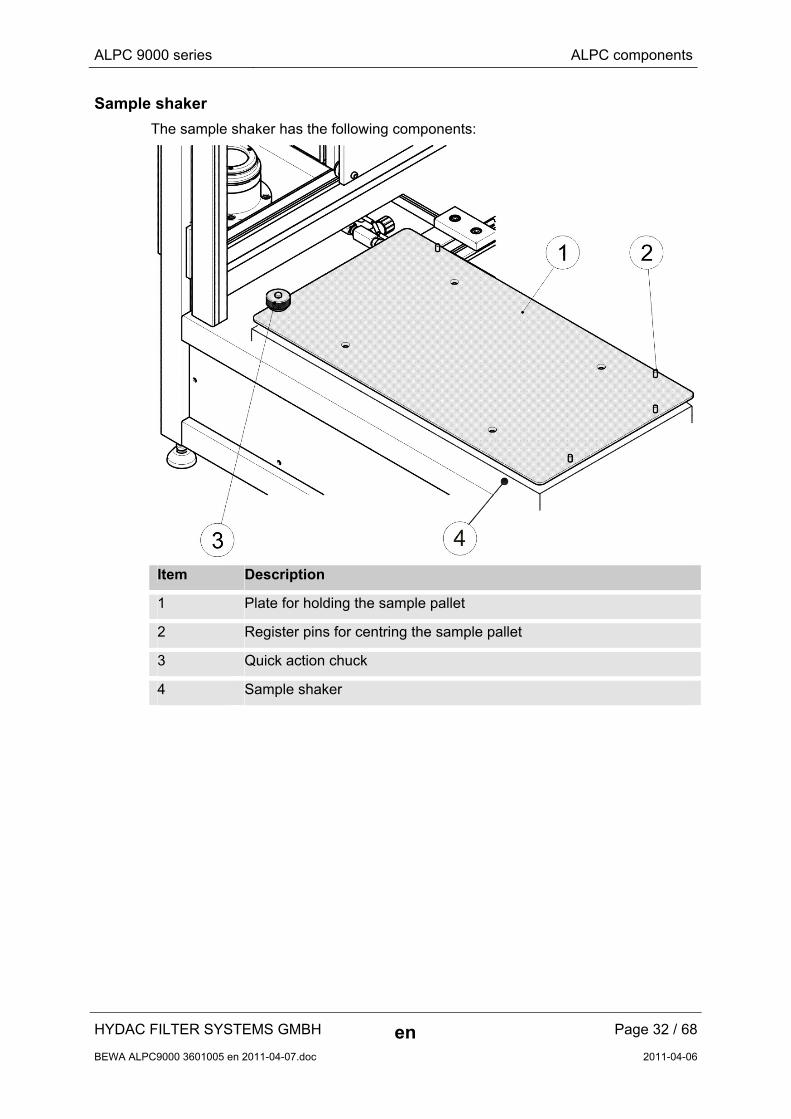
Sample shaker
The sample shaker has the following components:
Item Description
1 Plate for holding the sample pallet
2 Register pins for centring the sample pallet
3 Quick action chuck
4 Sample shaker
HYDAC FILTER SYSTEMS GMBH en Page 32 / 68
BEWA ALPC9000 3601005 en 2011-04-07.doc 2011-04-06
ALPC 9000 series Prior to switching the unit on
HYDAC FILTER SYSTEMS GMBH en Page 33 / 68
BEWA ALPC9000 3601005 en 2011-04-07.doc 2011-04-06
Prior to switching the unit on
Before switching the ALPC on, proceed through the following steps:
1. Check the flushing fluid tank for sufficient stocks of flushing fluid.
2. Check the suction hose. The suction hose must be located in the flushing fluid and may not draw in any air.
3. Empty the flushing return tank.
4. Check the return hose. The return hose must be located in the return tank.
5. Check all hoses for leaks and screw connections for signs of leakage.
6. Empty the collecting pans. If there is a lot of fluid located here, this may be an indication of leakage.
7. Check the O-ring on the pressure dome as described on page 48.
8. Clean the sealing disk on the vacuum hand as described on page 54.
9. Check the position on the EMERGENCY STOP switch (see page 28)
10. Check the switch positions on the robot controller (see page 30).
11. Check the maintenance unit (9).
Switch the compressed air for module V1 on.
Check the pressure on the pressure gauge. At least 6 bar are required for operation.
Drain any condensate / oil on the modules FR and FF.
12. Check the pressure dome position. If the pressure dome is located in the upper position, you can continue with Step (13).
If the pressure dome is located in a intermediate position, switch on the output (A003 - move dome upward) manually via the ALPCDesk software on I/O mode, and the pressure dome will move into the required upper position.
13. The preparations for switch-on have been completed. Continue to Chapter "Switching on the ALPC“ on page 34.
ALPC 9000 series Switching on the ALPC
HYDAC FILTER SYSTEMS GMBH en Page 34 / 68
BEWA ALPC9000 3601005 en 2011-04-07.doc 2011-04-06
Switching on the ALPC
To switch on the ALPC, proceed as follows:
1. After you have undertaken the steps in Chapter "Prior to switching the unit on“ on page 33:
2. Switch the PC on at the on/off switch.
3. Switch the ALPC on at the mains box main switch.
4. Carry out a lamp test on the mains box (see page 48).
5. Start the program ALPCDesk on the PC.
A detailed description of the ALPCDesk software can be found in the enclosed software instructions.
6. The ALPC is now ready for the analysis.
ALPC 9000 series Preparing sample bottles for analysis
Preparing sample bottles for analysis
Prepare the sample bottles for use as follows:
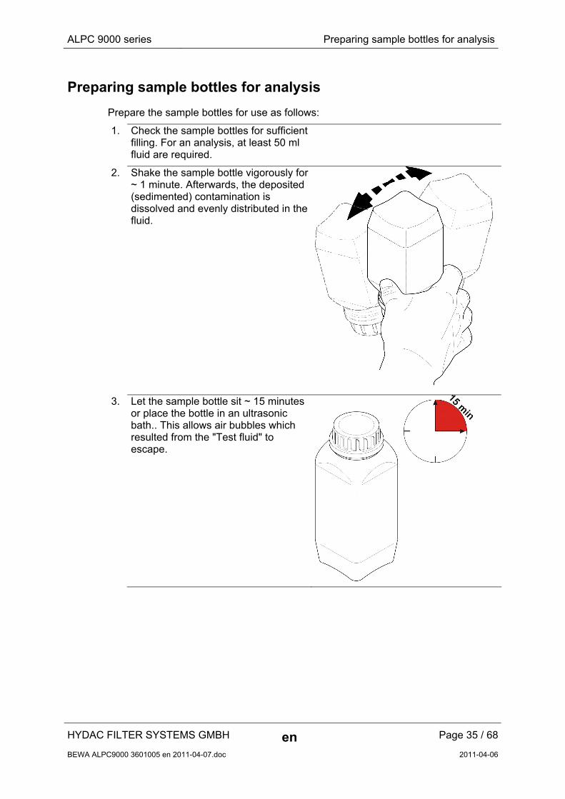
1. Check the sample bottles for sufficient filling. For an analysis, at least 50 ml fluid are required.
2. Shake the sample bottle vigorously for ~ 1 minute. Afterwards, the deposited (sedimented) contamination is dissolved and evenly distributed in the fluid.
3. Let the sample bottle sit ~ 15 minutes or place the bottle in an ultrasonic bath.. This allows air bubbles which resulted from the "Test fluid" to escape.
HYDAC FILTER SYSTEMS GMBH en Page 35 / 68
BEWA ALPC9000 3601005 en 2011-04-07.doc 2011-04-06
ALPC 9000 series Preparing sample bottles for analysis
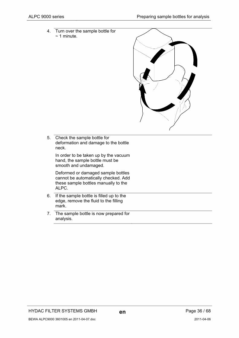
4. Turn over the sample bottle for ~ 1 minute.
5. Check the sample bottle for deformation and damage to the bottle neck.
In order to be taken up by the vacuum hand, the sample bottle must be smooth and undamaged.
Deformed or damaged sample bottles cannot be automatically checked. Add these sample bottles manually to the ALPC.
6. If the sample bottle is filled up to the edge, remove the fluid to the filling mark.
7. The sample bottle is now prepared for analysis.
HYDAC FILTER SYSTEMS GMBH en Page 36 / 68
BEWA ALPC9000 3601005 en 2011-04-07.doc 2011-04-06
ALPC 9000 series Preparing sample bottles for analysis
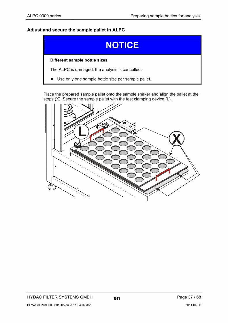
Adjust and secure the sample pallet in ALPC
NOTICE
Different sample bottle sizes
The ALPC is damaged; the analysis is cancelled.
► Use only one sample bottle size per sample pallet.
Place the prepared sample pallet onto the sample shaker and align the pallet at the stops (X). Secure the sample pallet with the fast clamping device (L).
HYDAC FILTER SYSTEMS GMBH en Page 37 / 68
BEWA ALPC9000 3601005 en 2011-04-07.doc 2011-04-06
ALPC 9000 series Preparing sample bottles for analysis
HYDAC FILTER SYSTEMS GMBH en Page 38 / 68
BEWA ALPC9000 3601005 en 2011-04-07.doc 2011-04-06
Change sample pallets 100 / 100 / 30 (optional)
NOTICE
Deviating sample bottle sizes / adaptor rings
The ALPC will be damaged
► Use only one sample bottle size per sample pallet.
► Only use the permitted sample bottles in the appropriate pallet.
► Replace the appropriate adaptor ring in the pressure dome when the pallet is changed.
The optionally available change pallets always have the same raster for holding max. 45 sample bottles.
Each change pallet is suitable for holding a certain type of sample bottle and has a colour code.

ALPC 9000 series Preparing sample bottles for analysis
In the following you will find the allocation of the colour code to the sample bottle type:
Adaptor ring Colour Sample jar
red
30 ml, glass
blue
100 ml, plastic MIDLAND, Monroe
green
100 ml, glass
HYDAC FILTER SYSTEMS GMBH en Page 39 / 68
BEWA ALPC9000 3601005 en 2011-04-07.doc 2011-04-06
ALPC 9000 series Perform analysis
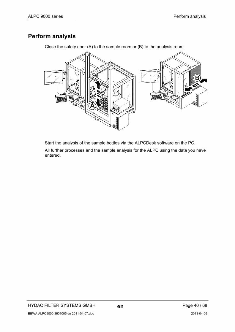
Perform analysis
Close the safety door (A) to the sample room or (B) to the analysis room.
Start the analysis of the sample bottles via the ALPCDesk software on the PC.
All further processes and the sample analysis for the ALPC using the data you have entered.
HYDAC FILTER SYSTEMS GMBH en Page 40 / 68
BEWA ALPC9000 3601005 en 2011-04-07.doc 2011-04-06
ALPC 9000 series Perform analysis
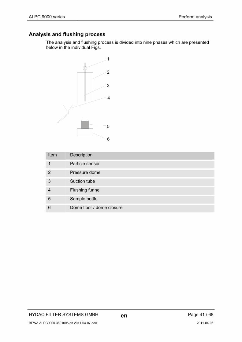
Analysis and flushing process
The analysis and flushing process is divided into nine phases which are presented below in the individual Figs.
1
2
4
3
5
6
Item Description
1 Particle sensor
2 Pressure dome
3 Suction tube
4 Flushing funnel
5 Sample bottle
6 Dome floor / dome closure
HYDAC FILTER SYSTEMS GMBH en Page 41 / 68
BEWA ALPC9000 3601005 en 2011-04-07.doc 2011-04-06
ALPC 9000 series Perform analysis
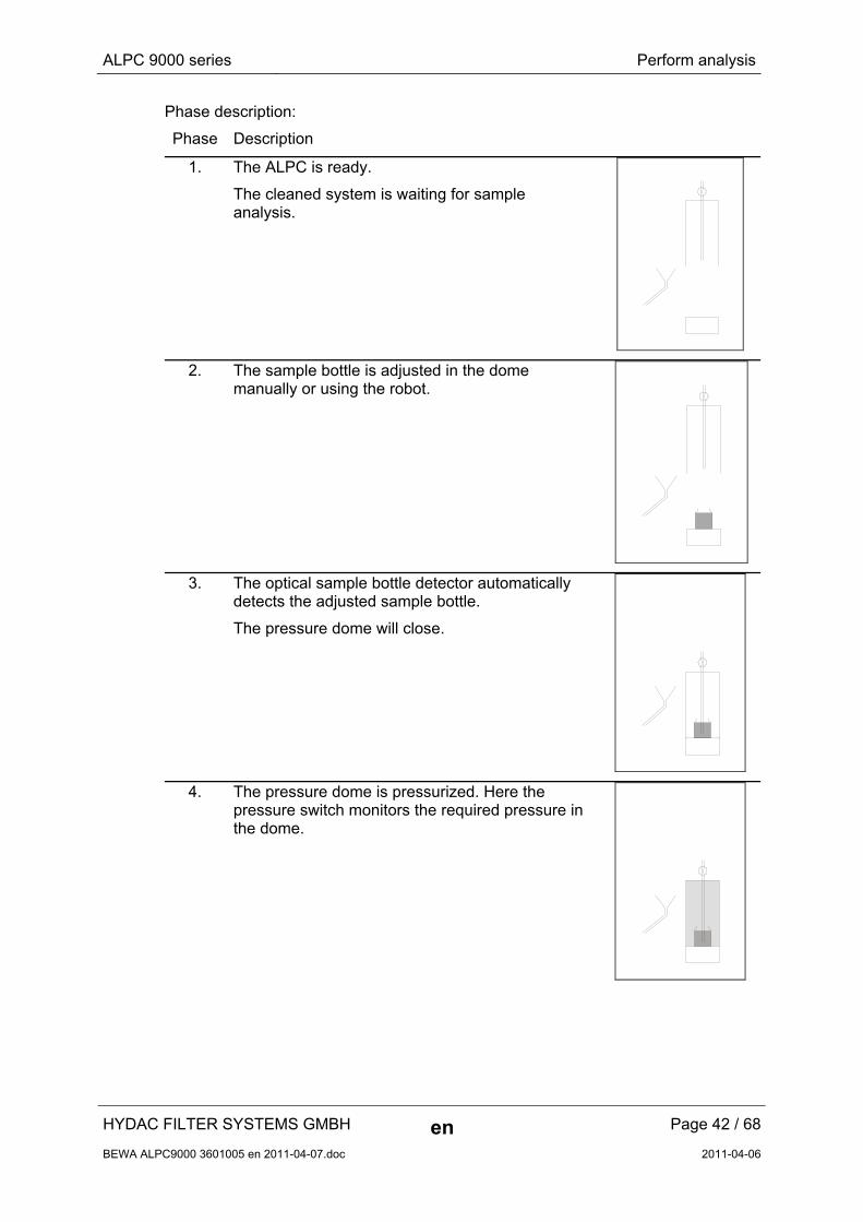
Phase description:
Phase Description
1. The ALPC is ready.
The cleaned system is waiting for sample analysis.
2. The sample bottle is adjusted in the dome manually or using the robot.
3. The optical sample bottle detector automatically detects the adjusted sample bottle.
The pressure dome will close.
4. The pressure dome is pressurized. Here the pressure switch monitors the required pressure in the dome.
HYDAC FILTER SYSTEMS GMBH en Page 42 / 68
BEWA ALPC9000 3601005 en 2011-04-07.doc 2011-04-06
ALPC 9000 series Perform analysis
HYDAC FILTER SYSTEMS GMBH en Page 43 / 68
BEWA ALPC9000 3601005 en 2011-04-07.doc 2011-04-06
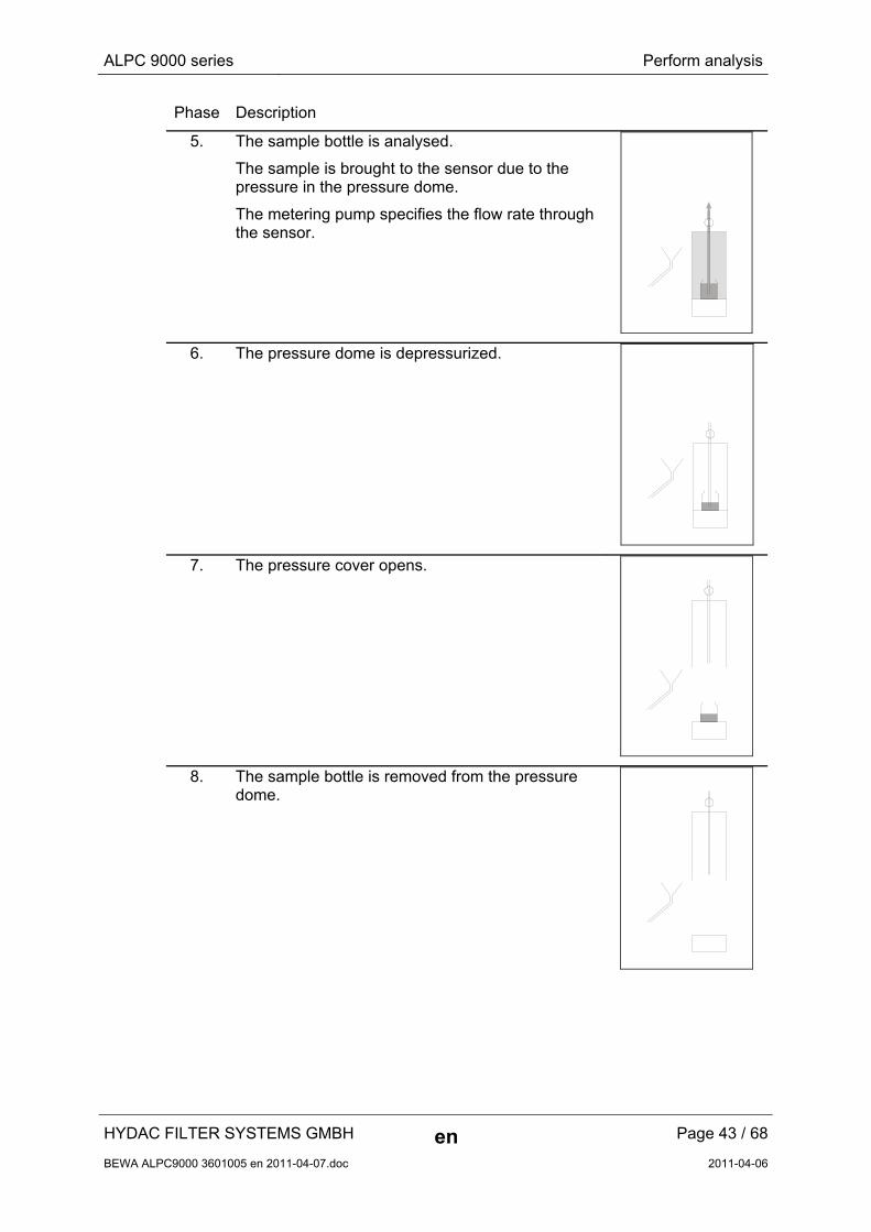
Phase Description
5. The sample bottle is analysed.
The sample is brought to the sensor due to the pressure in the pressure dome.
The metering pump specifies the flow rate through the sensor.
6. The pressure dome is depressurized.
7. The pressure cover opens.
8. The sample bottle is removed from the pressure dome.

ALPC 9000 series Perform analysis
HYDAC FILTER SYSTEMS GMBH en Page 44 / 68
BEWA ALPC9000 3601005 en 2011-04-07.doc 2011-04-06
Phase Description
9. The optical sample bottle detector detects the empty dome and swivels the funnel-shaped collector under the pressure dome. Then the ALPC starts by flushing the suction tube inside and outside.
This flushing process can be controlled through the level of contamination or through time.
1. The ALPC is ready for the next sample analysis.
ALPC 9000 series Switching off the ALPC
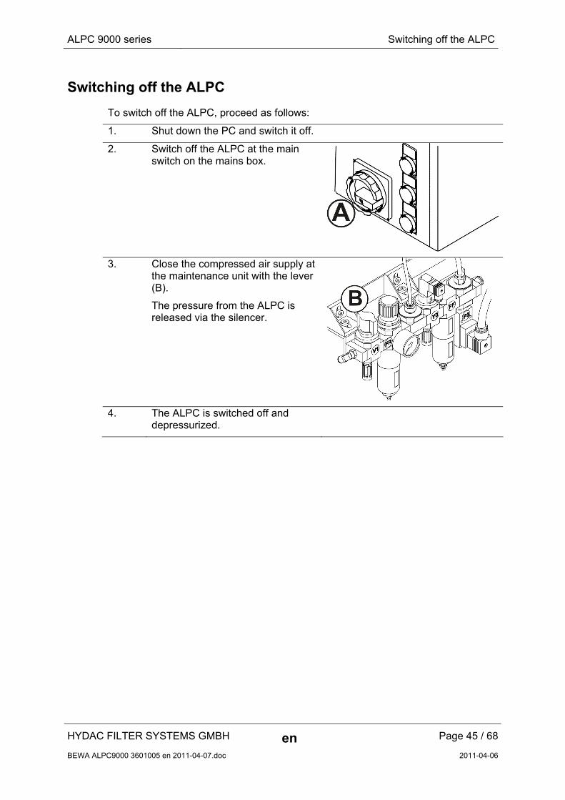
Switching off the ALPC
To switch off the ALPC, proceed as follows:
1. Shut down the PC and switch it off.
2. Switch off the ALPC at the main switch on the mains box.
3. Close the compressed air supply at the maintenance unit with the lever (B).
The pressure from the ALPC is released via the silencer.
4. The ALPC is switched off and depressurized.
HYDAC FILTER SYSTEMS GMBH en Page 45 / 68
BEWA ALPC9000 3601005 en 2011-04-07.doc 2011-04-06
ALPC 9000 series Performing Maintenance
HYDAC FILTER SYSTEMS GMBH en Page 46 / 68
BEWA ALPC9000 3601005 en 2011-04-07.doc 2011-04-06
Performing Maintenance
The maintenance and servicing to be performed periodically is described here. The ALPC's serviceability, operational reliability and life substantially depend on performing maintenance and servicing work regularly and carefully.
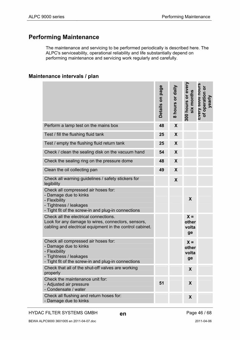
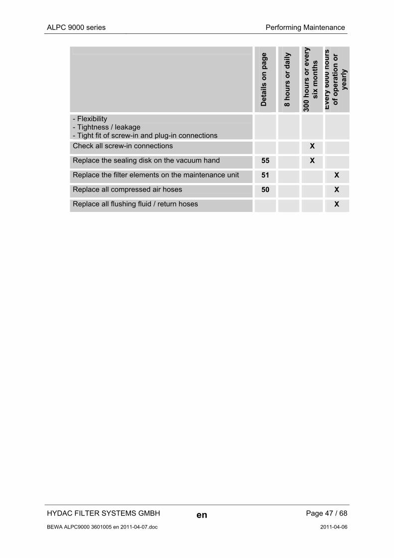
Maintenance intervals / plan
Det
ails
on
pag
e
8 h
ou
rs o
r d
aily
300
ho
urs
or
ever
y si
x m
on
ths
Eve
ry 6
000
ho
urs
o
f o
per
atio
n o
r ye
arly
Perform a lamp test on the mains box 48 X
Test / fill the flushing fluid tank 25 X
Test / empty the flushing fluid return tank 25 X
Check / clean the sealing disk on the vacuum hand 54 X
Check the sealing ring on the pressure dome 48 X
Clean the oil collecting pan 49 X
Check all warning guidelines / safety stickers for legibility
X
Check all compressed air hoses for: - Damage due to kinks - Flexibility - Tightness / leakages - Tight fit of the screw-in and plug-in connections
X
Check all the electrical connections. Look for any damage to wires, connectors, sensors, cabling and electrical equipment in the control cabinet.
X = other volta
ge
Check all compressed air hoses for: - Damage due to kinks - Flexibility - Tightness / leakages - Tight fit of the screw-in and plug-in connections
X = other volta
ge
Check that all of the shut-off valves are working properly
X
Check the maintenance unit for: - Adjusted air pressure - Condensate / water
51 X
Check all flushing and return hoses for: - Damage due to kinks
X
ALPC 9000 series Performing Maintenance
HYDAC FILTER SYSTEMS GMBH en Page 47 / 68
BEWA ALPC9000 3601005 en 2011-04-07.doc 2011-04-06
Det
ails
on
pag
e
8 h
ou
rs o
r d
aily
300
ho
urs
or
ever
y si
x m
on
ths
Eve
ry 6
000
ho
urs
o
f o
per
atio
n o
r ye
arly
- Flexibility - Tightness / leakage - Tight fit of screw-in and plug-in connections
Check all screw-in connections X
Replace the sealing disk on the vacuum hand 55 X
Replace the filter elements on the maintenance unit 51 X
Replace all compressed air hoses 50 X
Replace all flushing fluid / return hoses X
ALPC 9000 series Performing Maintenance
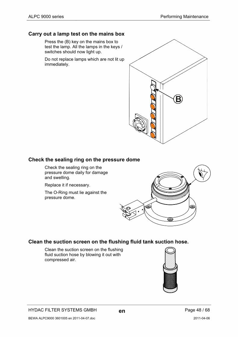
Carry out a lamp test on the mains box
Press the (B) key on the mains box to test the lamp. All the lamps in the keys / switches should now light up.
Do not replace lamps which are not lit up immediately.
Check the sealing ring on the pressure dome
Check the sealing ring on the pressure dome daily for damage and swelling.
Replace it if necessary.
The O-Ring must lie against the pressure dome.
Clean the suction screen on the flushing fluid tank suction hose.
Clean the suction screen on the flushing fluid suction hose by blowing it out with compressed air.
HYDAC FILTER SYSTEMS GMBH en Page 48 / 68
BEWA ALPC9000 3601005 en 2011-04-07.doc 2011-04-06
ALPC 9000 series Performing Maintenance
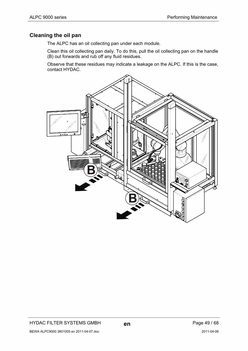
Cleaning the oil pan
The ALPC has an oil collecting pan under each module.
Clean this oil collecting pan daily. To do this, pull the oil collecting pan on the handle (B) out forwards and rub off any fluid residues.
Observe that these residues may indicate a leakage on the ALPC. If this is the case, contact HYDAC.
HYDAC FILTER SYSTEMS GMBH en Page 49 / 68
BEWA ALPC9000 3601005 en 2011-04-07.doc 2011-04-06
ALPC 9000 series Performing Maintenance
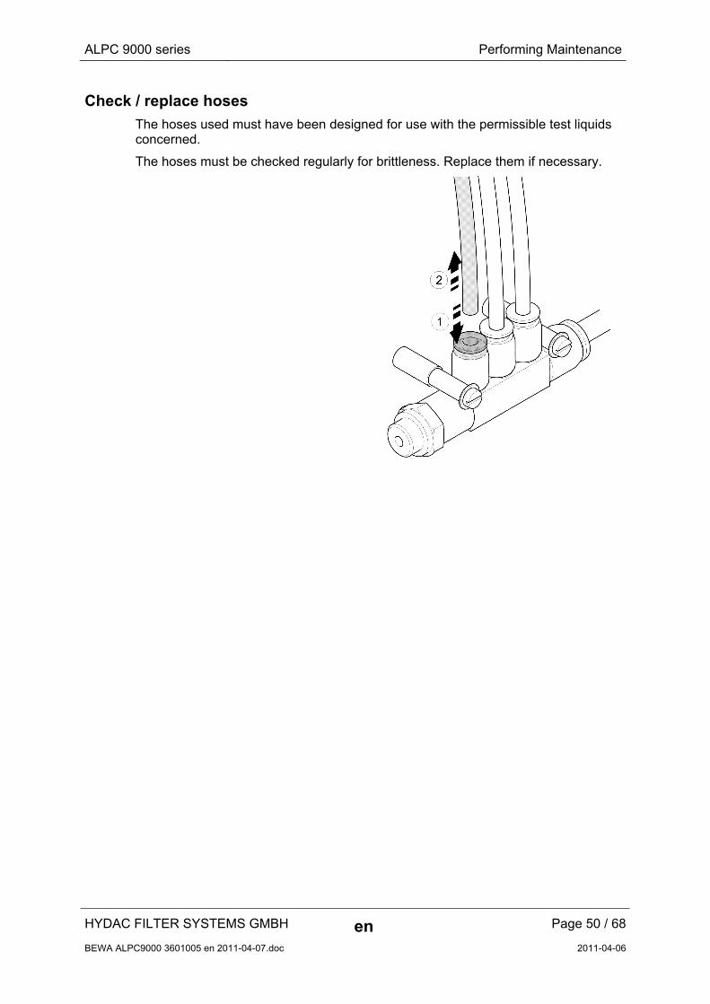
Check / replace hoses
The hoses used must have been designed for use with the permissible test liquids concerned.
The hoses must be checked regularly for brittleness. Replace them if necessary.
HYDAC FILTER SYSTEMS GMBH en Page 50 / 68
BEWA ALPC9000 3601005 en 2011-04-07.doc 2011-04-06
ALPC 9000 series Performing Maintenance
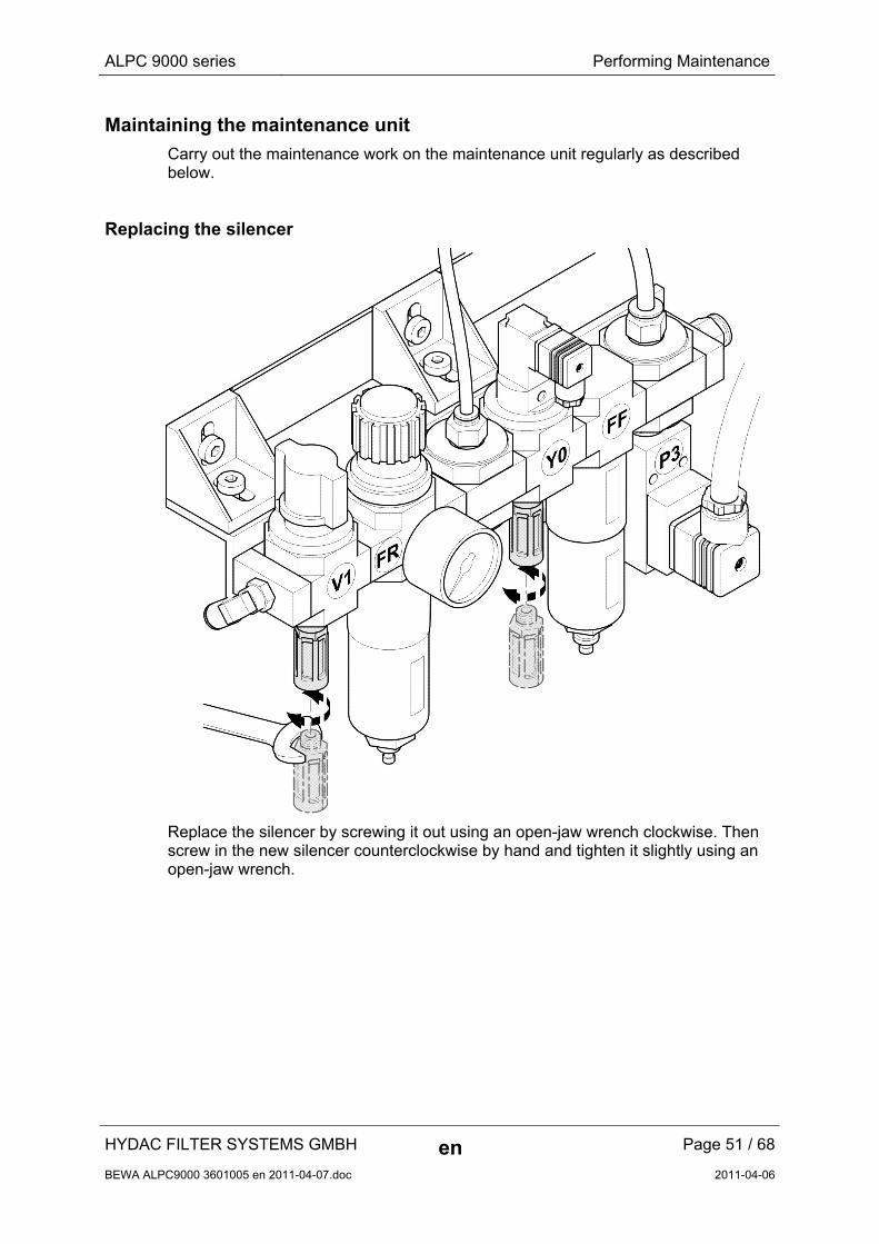
Maintaining the maintenance unit
Carry out the maintenance work on the maintenance unit regularly as described below.
Replacing the silencer
Replace the silencer by screwing it out using an open-jaw wrench clockwise. Then screw in the new silencer counterclockwise by hand and tighten it slightly using an open-jaw wrench.
HYDAC FILTER SYSTEMS GMBH en Page 51 / 68
BEWA ALPC9000 3601005 en 2011-04-07.doc 2011-04-06
ALPC 9000 series Performing Maintenance
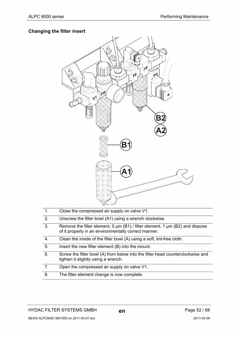
Changing the filter insert
1. Close the compressed air supply on valve V1.
2. Unscrew the filter bowl (A1) using a wrench clockwise.
3. Remove the filter element, 5 µm (B1) / filter element, 1 µm (B2) and dispose of it properly in an environmentally correct manner.
4. Clean the inside of the filter bowl (A) using a soft, lint-free cloth.
5. Insert the new filter element (B) into the mount.
6. Screw the filter bowl (A) from below into the filter head counterclockwise and tighten it slightly using a wrench.
7. Open the compressed air supply on valve V1.
8. The filter element change is now complete.
HYDAC FILTER SYSTEMS GMBH en Page 52 / 68
BEWA ALPC9000 3601005 en 2011-04-07.doc 2011-04-06
ALPC 9000 series Performing Maintenance
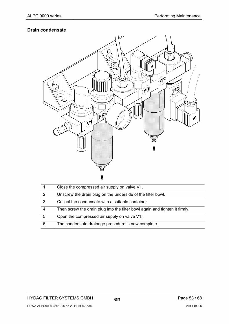
Drain condensate
1. Close the compressed air supply on valve V1.
2. Unscrew the drain plug on the underside of the filter bowl.
3. Collect the condensate with a suitable container.
4. Then screw the drain plug into the filter bowl again and tighten it firmly.
5. Open the compressed air supply on valve V1.
6. The condensate drainage procedure is now complete.
HYDAC FILTER SYSTEMS GMBH en Page 53 / 68
BEWA ALPC9000 3601005 en 2011-04-07.doc 2011-04-06
ALPC 9000 series Performing Maintenance
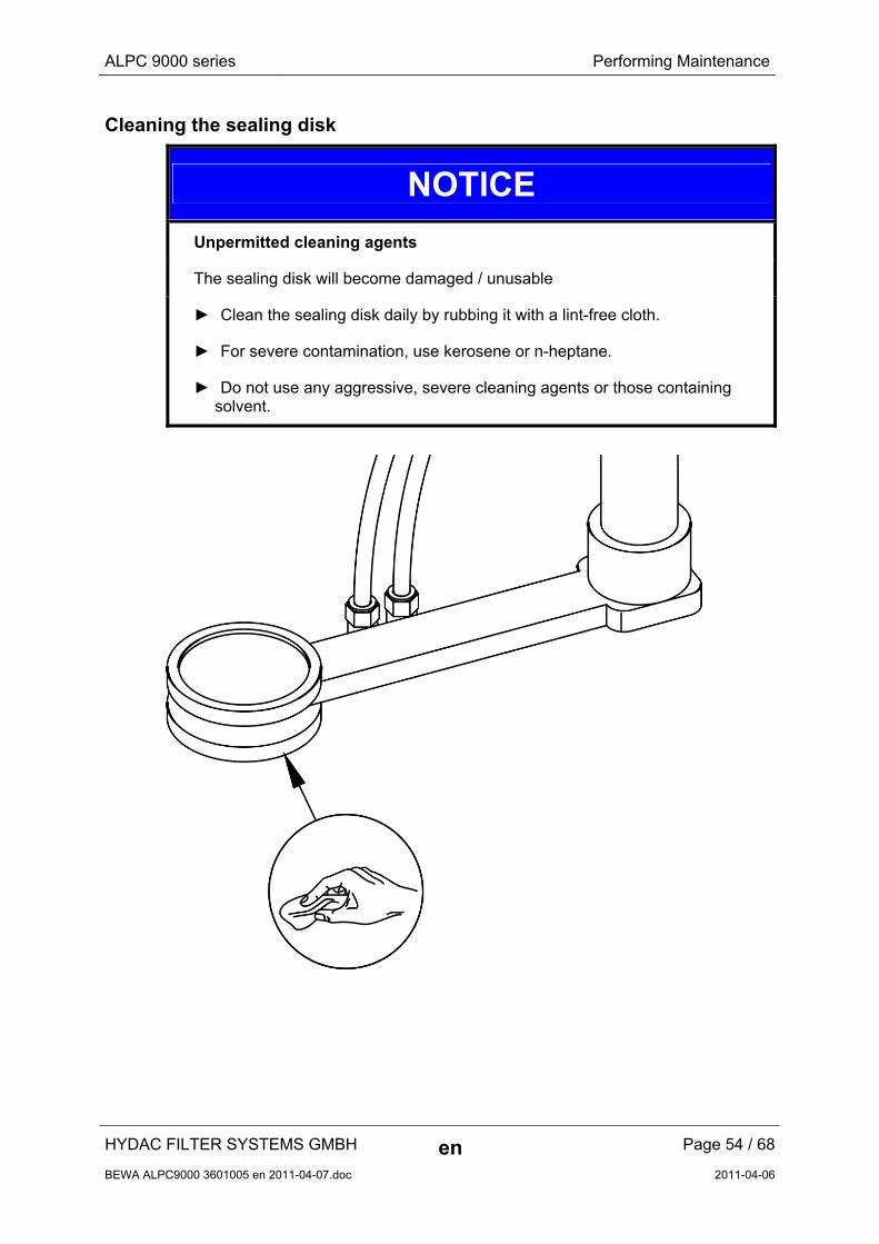
Cleaning the sealing disk
NOTICE
Unpermitted cleaning agents
The sealing disk will become damaged / unusable
► Clean the sealing disk daily by rubbing it with a lint-free cloth.
► For severe contamination, use kerosene or n-heptane.
► Do not use any aggressive, severe cleaning agents or those containing solvent.
HYDAC FILTER SYSTEMS GMBH en Page 54 / 68
BEWA ALPC9000 3601005 en 2011-04-07.doc 2011-04-06
ALPC 9000 series Performing Maintenance
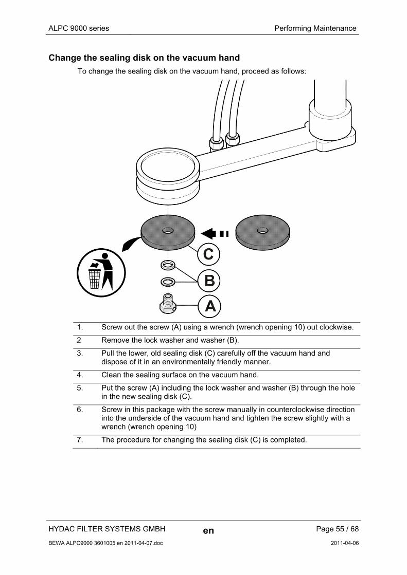
Change the sealing disk on the vacuum hand
To change the sealing disk on the vacuum hand, proceed as follows:
1. Screw out the screw (A) using a wrench (wrench opening 10) out clockwise.
2 Remove the lock washer and washer (B).
3. Pull the lower, old sealing disk (C) carefully off the vacuum hand and dispose of it in an environmentally friendly manner.
4. Clean the sealing surface on the vacuum hand.
5. Put the screw (A) including the lock washer and washer (B) through the hole in the new sealing disk (C).
6. Screw in this package with the screw manually in counterclockwise direction into the underside of the vacuum hand and tighten the screw slightly with a wrench (wrench opening 10)
7. The procedure for changing the sealing disk (C) is completed.
HYDAC FILTER SYSTEMS GMBH en Page 55 / 68
BEWA ALPC9000 3601005 en 2011-04-07.doc 2011-04-06
ALPC 9000 series Performing Maintenance
HYDAC FILTER SYSTEMS GMBH en Page 56 / 68
BEWA ALPC9000 3601005 en 2011-04-07.doc 2011-04-06
Replacing the vacuum hoses on the robot
In order to replace the vacuum hoses on the robot, please proceed as follows:
Step Description Page
1. Dismantling the rear wall on the protective housing 57
2.. Replace the vacuum hoses 58
3. Changing the silencer on the vacuum generator 58
4. Mounting the rear wall of the protective housing 59
ALPC 9000 series Performing Maintenance
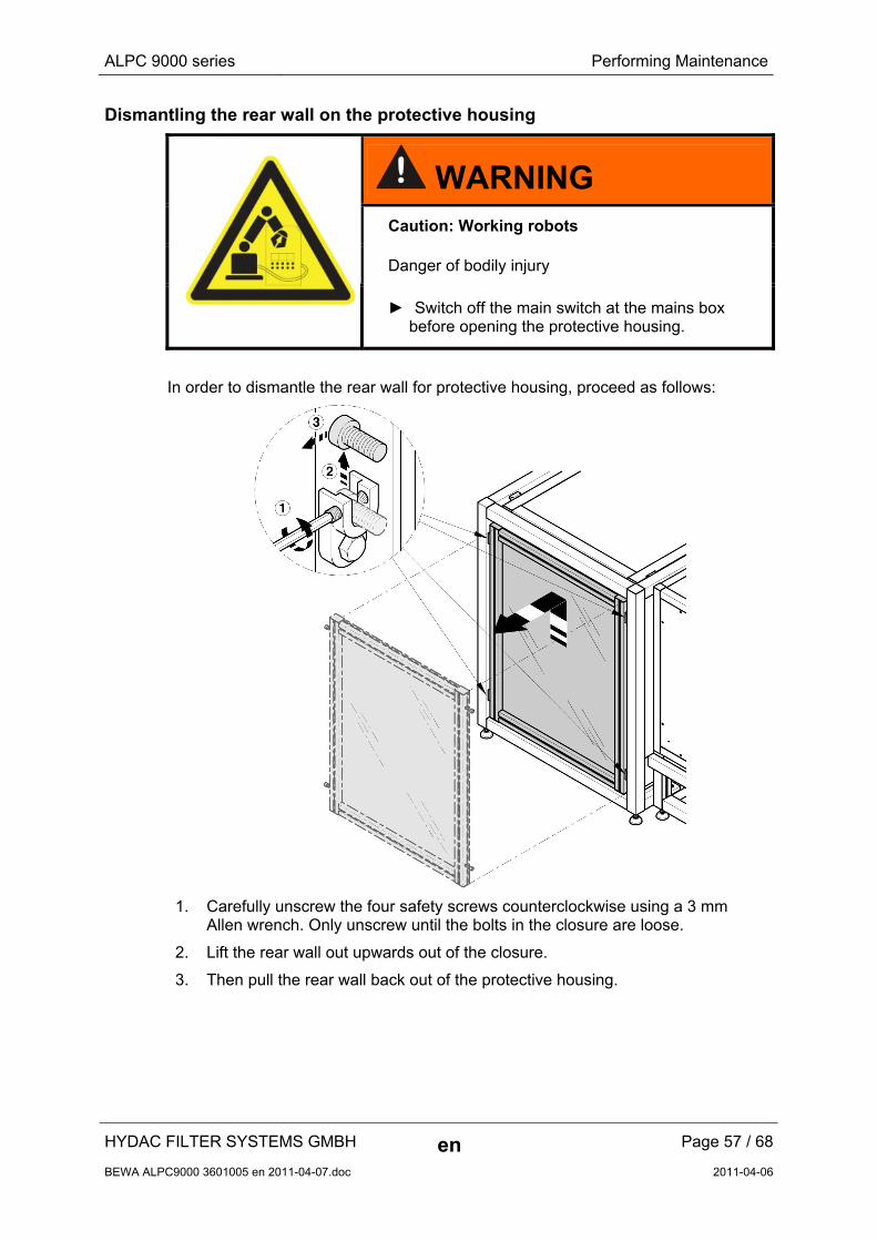
Dismantling the rear wall on the protective housing
WARNING Caution: Working robots
Danger of bodily injury
► Switch off the main switch at the mains box before opening the protective housing.
In order to dismantle the rear wall for protective housing, proceed as follows:
1. Carefully unscrew the four safety screws counterclockwise using a 3 mm Allen wrench. Only unscrew until the bolts in the closure are loose.
2. Lift the rear wall out upwards out of the closure.
3. Then pull the rear wall back out of the protective housing.
HYDAC FILTER SYSTEMS GMBH en Page 57 / 68
BEWA ALPC9000 3601005 en 2011-04-07.doc 2011-04-06
ALPC 9000 series Performing Maintenance
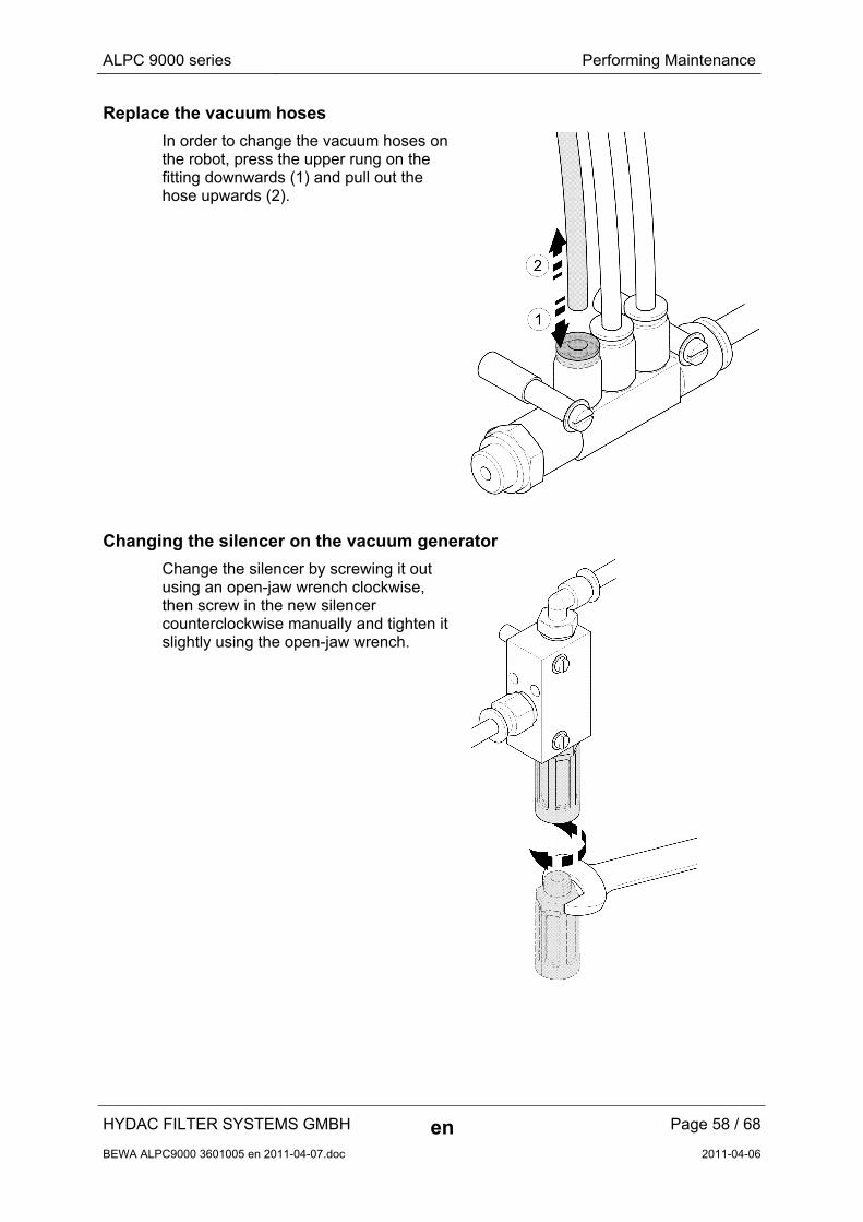
Replace the vacuum hoses
In order to change the vacuum hoses on the robot, press the upper rung on the fitting downwards (1) and pull out the hose upwards (2).
Changing the silencer on the vacuum generator
Change the silencer by screwing it out using an open-jaw wrench clockwise, then screw in the new silencer counterclockwise manually and tighten it slightly using the open-jaw wrench.
HYDAC FILTER SYSTEMS GMBH en Page 58 / 68
BEWA ALPC9000 3601005 en 2011-04-07.doc 2011-04-06
ALPC 9000 series Performing Maintenance
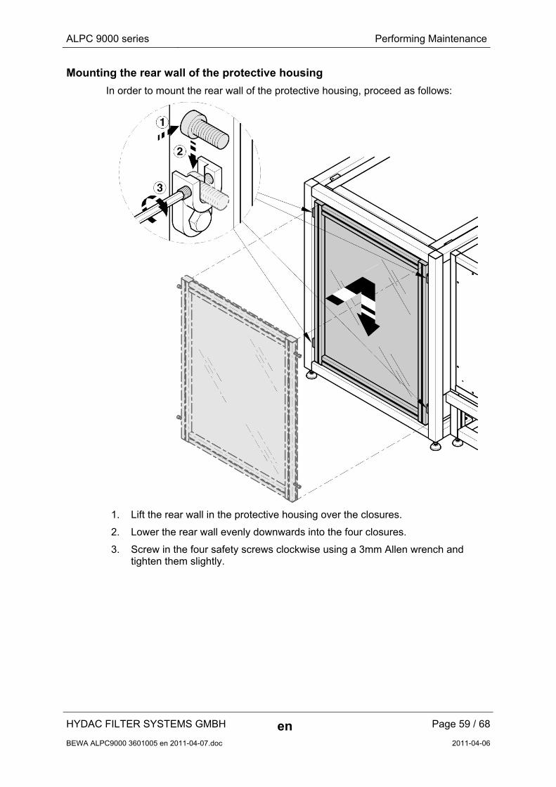
Mounting the rear wall of the protective housing
In order to mount the rear wall of the protective housing, proceed as follows:
1. Lift the rear wall in the protective housing over the closures.
2. Lower the rear wall evenly downwards into the four closures.
3. Screw in the four safety screws clockwise using a 3mm Allen wrench and tighten them slightly.
HYDAC FILTER SYSTEMS GMBH en Page 59 / 68
BEWA ALPC9000 3601005 en 2011-04-07.doc 2011-04-06
ALPC 9000 series Pneumatic / hydraulic diagram
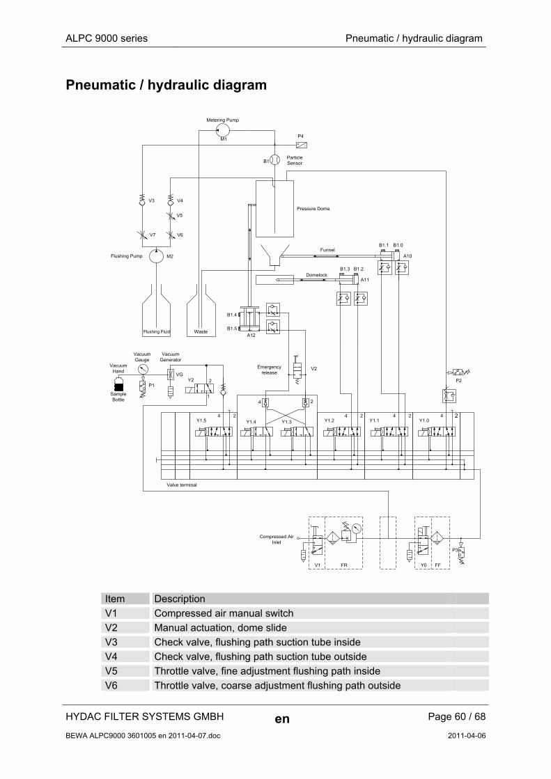
Pneumatic / hydraulic diagram
Y1.3 Y1.2 Y1.1 Y1.0
B1.2B1.3
Compressed AirInlet
B1.0B1.1
Domelock
Funnel
Waste Flushing Fluid
Metering Pump
Particle Sensor
Flushing Pump
Pressure Dome
B1.5
B1.4
Vacuum Hand
Vacuum Gauge
Valve terminal
P3
P2
P4
P1
B1
V4V3
Emergency release
Y1.5
Vacuum Generator
Y1.4
V1 FR FFY0
242424
24
24
M1
M2
V5
V6V7
VG
SampleBottle
A10
A11
A12
V2
IP
2
1
Y2
Item Description
V1 Compressed air manual switch
V2 Manual actuation, dome slide
V3 Check valve, flushing path suction tube inside
V4 Check valve, flushing path suction tube outside
V5 Throttle valve, fine adjustment flushing path inside
V6 Throttle valve, coarse adjustment flushing path outside
HYDAC FILTER SYSTEMS GMBH en Page 60 / 68
BEWA ALPC9000 3601005 en 2011-04-07.doc 2011-04-06
ALPC 9000 series Pneumatic / hydraulic diagram
HYDAC FILTER SYSTEMS GMBH en Page 61 / 68
BEWA ALPC9000 3601005 en 2011-04-07.doc 2011-04-06
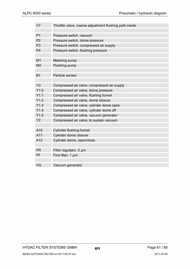
V7 Throttle valve, coarse adjustment flushing path inside
P1 Pressure switch, vacuum
P2 Pressure switch, dome pressure
P3 Pressure switch, compressed air supply
P4 Pressure switch, flushing pressure
M1 Metering pump
M2 Flushing pump
B1 Particle sensor
Y0 Compressed air valve, compressed air supply
Y1.0 Compressed air valve, dome pressure
Y1.1 Compressed air valve, flushing funnel
Y1.2 Compressed air valve, dome closure
Y1.3 Compressed air valve, cylinder dome open
Y1.4 Compressed air valve, cylinder dome off
Y1.5 Compressed air valve, vacuum generator
Y2 Compressed air valve, to sustain vacuum
A10 Cylinder flushing funnel
A11 Cylinder dome closure
A12 Cylinder dome, open/close
FR Filter regulator, 5 µm
FF Fine filter, 1 µm
VG Vacuum generator
ALPC 9000 series Spare Parts List
HYDAC FILTER SYSTEMS GMBH en Page 62 / 68
BEWA ALPC9000 3601005 en 2011-04-07.doc 2011-04-06
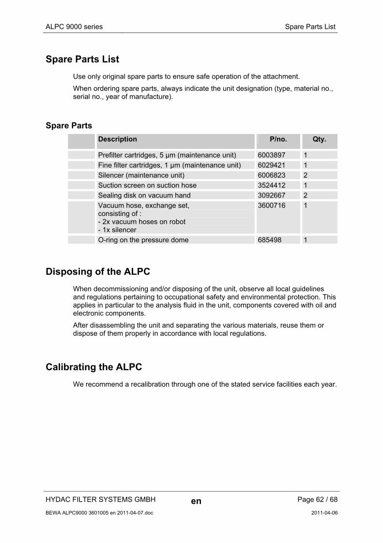
Spare Parts List
Use only original spare parts to ensure safe operation of the attachment.
When ordering spare parts, always indicate the unit designation (type, material no., serial no., year of manufacture).
Spare Parts
Description P/no. Qty.
Prefilter cartridges, 5 µm (maintenance unit) 6003897 1
Fine filter cartridges, 1 µm (maintenance unit) 6029421 1
Silencer (maintenance unit) 6006823 2
Suction screen on suction hose 3524412 1
Sealing disk on vacuum hand 3092667 2
Vacuum hose, exchange set, consisting of : - 2x vacuum hoses on robot - 1x silencer
3600716 1
O-ring on the pressure dome 685498 1
Disposing of the ALPC
When decommissioning and/or disposing of the unit, observe all local guidelines and regulations pertaining to occupational safety and environmental protection. This applies in particular to the analysis fluid in the unit, components covered with oil and electronic components.
After disassembling the unit and separating the various materials, reuse them or dispose of them properly in accordance with local regulations.
Calibrating the ALPC
We recommend a recalibration through one of the stated service facilities each year.
ALPC 9000 series Customer Service
HYDAC FILTER SYSTEMS GMBH en Page 63 / 68
BEWA ALPC9000 3601005 en 2011-04-07.doc 2011-04-06
Customer Service
Current contacts for product support/customer service, repair and spare parts can always be found on our website at www.hydac.com.
For calibration, contact one of the following HYDAC national subsidiaries:
Germany
HYDAC Service GmbH Product Support, Werk 10 66128 Saarbruecken
Telephone: +49 (0) 6897 509 1938
Telefax: +49 (0) 6897 509 1933
E-mail: [email protected]
USA
HYDAC Technology Corporation, HYCON Division 2260 City Line Road USA-Bethlehem, PA 18017 P.O. Box 22050 USA-Lehigh Valley, PA 18002-2050 Telephone: +1 (0) 610 266 01 00
Telefax: +1 (0) 610 231 04 45
E-mail: [email protected]
Internet: www.hydacusa.com
Australia
HYDAC Pty. Ltd. 109 Dohertys Road P.O. Box 224 AUS-3025 Altona North
Telephone: +61 - 3 - 92 72 89 00
Telefax: +61 - 3 - 93 69 89 12
E-mail: [email protected]
ALPC 9000 series Customer Service
HYDAC FILTER SYSTEMS GMBH en Page 64 / 68
BEWA ALPC9000 3601005 en 2011-04-07.doc 2011-04-06
Brazil
HYDAC TECNOLOGIA LTDA Estrada Fukutaro Yida, 225 CEP 09852-060 Cooperativa BR-São Bernardo do Campo – SÃO PAULO
Telephone: +55 - 11 - 4393.6600
Telefax: +55 - 11 - 4393.6617
E-mail: [email protected]
Homepage www.hydac.com.br
ALPC 9000 series Technical data
HYDAC FILTER SYSTEMS GMBH en Page 65 / 68
BEWA ALPC9000 3601005 en 2011-04-07.doc 2011-04-06
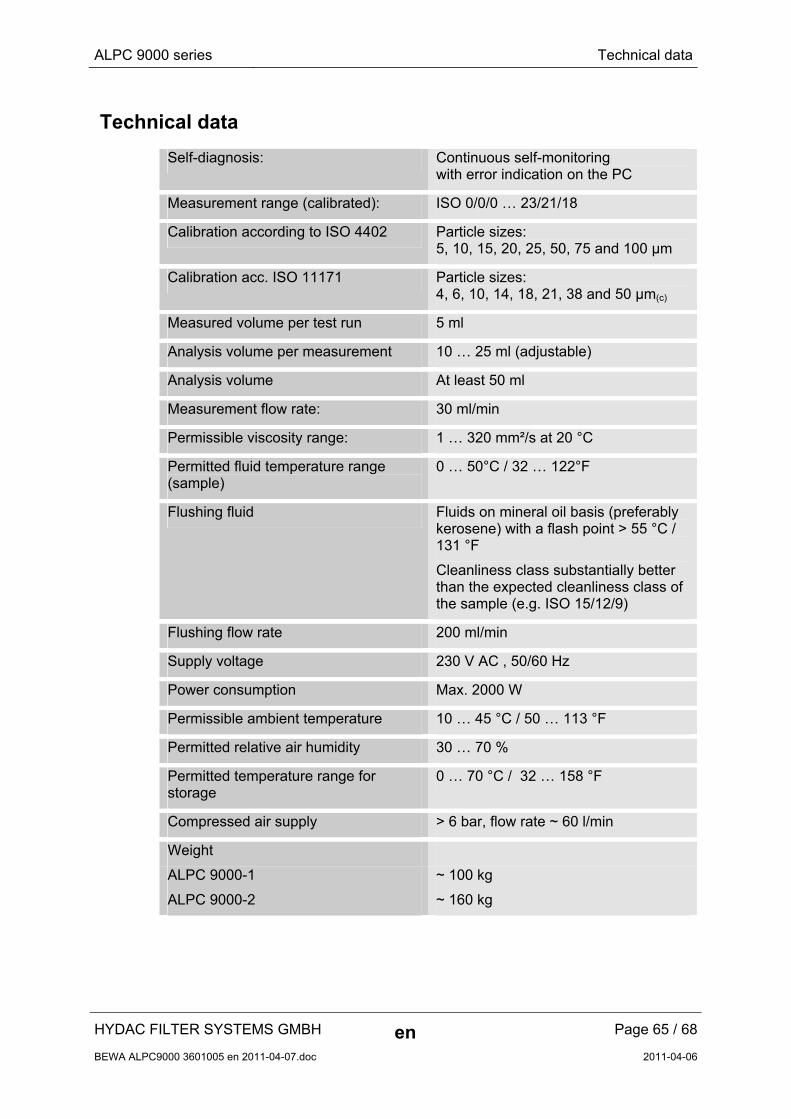
Technical data
Self-diagnosis: Continuous self-monitoring with error indication on the PC
Measurement range (calibrated): ISO 0/0/0 … 23/21/18
Calibration according to ISO 4402 Particle sizes: 5, 10, 15, 20, 25, 50, 75 and 100 µm
Calibration acc. ISO 11171 Particle sizes: 4, 6, 10, 14, 18, 21, 38 and 50 µm(c)
Measured volume per test run 5 ml
Analysis volume per measurement 10 … 25 ml (adjustable)
Analysis volume At least 50 ml
Measurement flow rate: 30 ml/min
Permissible viscosity range: 1 … 320 mm²/s at 20 °C
Permitted fluid temperature range (sample)
0 … 50°C / 32 … 122°F
Flushing fluid Fluids on mineral oil basis (preferably kerosene) with a flash point > 55 °C / 131 °F
Cleanliness class substantially better than the expected cleanliness class of the sample (e.g. ISO 15/12/9)
Flushing flow rate 200 ml/min
Supply voltage 230 V AC , 50/60 Hz
Power consumption Max. 2000 W
Permissible ambient temperature 10 … 45 °C / 50 … 113 °F
Permitted relative air humidity 30 … 70 %
Permitted temperature range for storage
0 … 70 °C / 32 … 158 °F
Compressed air supply > 6 bar, flow rate ~ 60 l/min
Weight
ALPC 9000-1 ~ 100 kg
ALPC 9000-2 ~ 160 kg

ALPC 9000 series Model Code
HYDAC FILTER SYSTEMS GMBH en Page 66 / 68
BEWA ALPC9000 3601005 en 2011-04-07.doc 2011-04-06
Model Code
ALPC 9000 - 1 - M - WXPDE - DE
Product ALPC = Automated laboratory particle counter Series 9000 = 9000 series Sample supply 1 = Manual 2 = Automatic Supply voltage M = 230 V AC , 50/60 Hz / 1 Phase PC-Operating system WXPUS = Windows XP, language US WXPDE = Windows XP, language DE W7 = Windows 7, Multilingual Keyboard layout BE = Belgium CH = Switzerland DE = Germany DK = Denmark ES = Spanish FR = France GB = England IT = Italy NO = Norway PO = Portugal SF = Sweden / Finland US = USA RU = Russia PL = Poland SK = Slovakia

HYDAC FILTER SYSTEMS GMBH Industriegebiet Postfach 1251 66280 Sulzbach/Saar 66273 Sulzbach/Saar Germany Germany Phone: +49 (0) 6897 509 01 Central Fax: +49 (0) 6897 509 846 Technical Department Fax: +49 (0) 6897 509 577 Sales Department Internet: www.hydac.com E-Mail: [email protected]