Embed Size (px)
Citation preview

HYDRO-PNEUMATIC SERIES PRESSES OVERVIEW, INSTALLATION, AND OPERATION
AUTOMATED INDUSTRIAL MACHINE, INC TOGGLE-AIRE DIVISION
347 Farnum Pike
Smithfield, RI, USA 02917
401-232-1710
www.joraco.com
Installation, Operation and Maintenance
Hydro-Pneumatic Series Bench Presses

HYDRO-PNEUMATIC SERIES PRESSES OVERVIEW, INSTALLATION, AND OPERATION
IMPORTANT
It is the responsibility of the employer/purchaser to provide
his or her employees with proper point of operation guards,
and to ensure that this equipment is used in accordance with
the manufacturer's recommendations as well as any OSHA,
federal, or state regulations that are applicable to such
equipment. Because it is impossible to anticipate the
conditions under which our equipment will be operated,
additional safety devices and methods may be required to
ensure operator safety. Besides conforming to all federal,
state, and local codes, the buyer should consider the safety
of the entire operation involving any press, and see that any
additional guarding, training, and maintenance deemed
necessary is developed and enforced to protect the wellbeing
of the operator.
THINK SAFETY . . .
. . .WORK SAFELY
COPYRIGH T 201 9 by
AUTOMATED INDUSTRIAL MACHINE, INC. Smithfield, RI, USA All rights reserved

HYDRO-PNEUMATIC SERIES PRESSES OVERVIEW, INSTALLATION, AND OPERATION
Index Section I - Press Overview
1.1 - Description 1.2 - Features 1.3 – Options 1.4 – Cylinder Components 1.5 - Function
Section II - Valving 2.1 – Pneumatic Circuit 2.2 – Valving Connections Section III - Installation 3.1 – Un-boxing 3.2 - Synchro-Sig Installation 3.3 – Mounting Press 3.4 – Connect Air Supply 3.5 – Turn On Air Supply 3.6 – Test the Installation Section IV - Set-Up and Operation 4.1 - Mounting Tooling
4.2 - Stroke Limitation
Section V - Venting, Purging, Filling 5.1 – Vent / Fill
5.2 – Purge / fill Section VI - Troubleshooting 6.1 - Ram Will Not Extend 6.2 - Ram Will Not Retract
6.3 - Cylinder Will Not Switch to Power Stroke Cycle
6.4 - Frequent Oil Fills 6.5 – Press Not Generating Pressure
6.5 – Ram Will Not Fully Retract Section VII - Engineering Data
7.1 Standard Specifications 7.2 Cylinder Mounting 7.3 Bolster Plate Mounting 7.4 Cycle Times Charts
7.5 Force Section VIII – Replacement Parts
8.1 Replacement Parts List

HYDRO-PNEUMATIC SERIES PRESSES OVERVIEW, INSTALLATION, AND OPERATION
1
Section I: Press Overview
1.1 Description
The Hydro-Pneumatic (HP) Series Press is a completely self-contained, air-over-oil unit that is cost-effective and can be used in a variety of assembly and forming applications including punching, marking, staking, cutting, crimping and flaring. Our HP presses are available in sizes from 2 to 16 tons and the standard specifications are: 4” stroke with up to ½” power stroke, 8” open height, 20” between columns and an 8” x 10” precision ground bolster plate. Our HP Series Presses cut down on air consumption but still deliver the maximum force required for your application. 1.2 Features
• Self-contained
• Clean
• Quiet
• Adaptable
• No springs
• Only 3 moving components
• No external hydraulics 1.3 Options
• EZ-Dial Force Regulator
• Adjustable Output
• Filter, Regulator, Lubricator (FRL) – clean room compliance
• Dwell Timer
• Non-Rotating Ram
• Can be PLC ready for automated setups and force monitoring packages
*** Custom Features may be quoted upon request *** C-Frame option also available upon request
*** HP Series Cylinders also sold separately

HYDRO-PNEUMATIC SERIES PRESSES OVERVIEW, INSTALLATION, AND OPERATION
2
1.4 Cylinder Components
Item No. Description
1 High Pressure Advance
2 Rapid Advance
3 High Pressure Intensifier
4 High Pressure Cylinder Head
5 High Pressure Intermediate Cylinder Head
6 Low Pressure Intermediate Cylinder Head
7 Low Pressure Cylinder Head
8 Tie Rod Plate
9 Ram
10 Tie Rod
11 Venting Plug
12 Pressure Gauge
13 4 Way Valve
14 Bleed / Fill Valve
15 HP Sensor

HYDRO-PNEUMATIC SERIES PRESSES OVERVIEW, INSTALLATION, AND OPERATION
3
1.5 Function
Cylinder Retracted For the cylinder to retract, compressed air is supplied to ports A1 and A2, fully retracting the high pressure, rapid advance and intensifier pistons.
Rapid Advance For the cylinder to begin rapid advance, compressed air is supplied to port B1. This forces the rapid advance piston down towards the working end of the cylinder, forcing oil from the reservoir to the top of the intensifier piston until resistance is met.

HYDRO-PNEUMATIC SERIES PRESSES OVERVIEW, INSTALLATION, AND OPERATION
4
Power Stroke For the cylinder to begin the power stroke, compressed air is supplied to port B2. This forces the high pressure piston and rod down towards the working end of the cylinder. The high pressure piston and rod travel until reaching the high pressure seal, which will be the point at which pressure begins to build. As the rod and piston continue traveling, oil that was displaced during the rapid advance is compressed and builds pressure. Once the work has been completed the cylinder will then retract as mentioned above.
Power Stroke Only Option HP Series Presses are also sold as power stroke only. This will simply eliminate the rapid advance section and shorten the total travel of the cylinder. For the cylinder to begin the power stroke, compressed air is supplied to port B2. This forces the high-pressure piston and rod down towards the working end of the cylinder. In the power stroke only configuration the high pressure piston and rod are always in contact with the high pressure seal. This means that as soon as compressed air is supplied to port B2 the cylinder will begin building pressure. As the high pressure piston and rod continue traveling the oil is compressed and builds pressure. The cylinder will retract when compressed air is supplied to ports A1 and C1.

HYDRO-AIRE SERIES PRESSES INSTALLATION, OPERATION, AND MAINTENANCE
5
Section II: Valving
2.1 Pneumatic Circuit

HYDRO-AIRE SERIES PRESSES INSTALLATION, OPERATION, AND MAINTENANCE
6
2.2 Valving Connections
Valving Connections Valving Description
1-1 Rapid Advance
2-2 Low Pressure Retract
3-3 High Pressure Retract
4-4 High Pressure Advance
5-5 High Pressure Signal (S)
6-6 High Pressure Power (P)

HYDRO-AIRE SERIES PRESSES INSTALLATION, OPERATION, AND MAINTENANCE
7
Section III: Installation 3.1 Un-boxing Carefully remove the press from the crate, taking note of separately packed items such as the "Quick Exhaust Unit"(Optional), FRL Unit (Optional) and "Synchro-Sig" Actuator.
Synchro-Sig may come mounted on some models 3.2 Synchro-Sig Installation
A. Locate the 1/4" yellow tubing found under the press platen. Connect the tubing to the appropriate fittings on the actuator. See markings on the tubing. DO NOT OVERTIGHTEN normally, 1/2 turn past finger tight is sufficient for an airtight connection. (Figure 1.1)
B. Using the 1/4-20 hex head bolts supplied, mount the "Synchro-Sig" to the press as shown. Be sure to mount the aluminum lever guard between the actuator and the press at the same time. (Figure 1.2)
NOTE: To ensure operator safety some applications may require that you locate the "Synchro-Sig" actuator further away from your tooling.
- PICTURES ARE FOR REFERENCE ONLY- SOME SECTIONS OF THIS MANUAL MAY NOT APPLY TO YOUR PRESS UNIT.

HYDRO-AIRE SERIES PRESSES INSTALLATION, OPERATION, AND MAINTENANCE
8
3.3 Mounting Press
A. Select a bench of suitable size and strength. B. Bolt the press to the bench using the holes located
in the press frame below the platen area. Never operate the press unless it is securely mounted on a bench or stand. (Figure 1.3)
3.4 Connect Air Supply
A. The air supply must be clean and conditioned. Preferably, a Filter, Regulator, Lubricator Unit, (Joraco Part No. FRL-HP) should be located within 6 feet of the press. For optimum results all air lines, fittings, and hoses used to supply the press should be the equivalent of 1/2" minimum.
B. The minimum air pressure for operation is 50 PSI;
the maximum is 100 PSI. The optimum operating range is 60-100 PSI. If your application consistently required substantially more than 100 PSI it may indicate the need for a stronger press.
C. Connect air supply to the press at the inlet port.
NOTE: If lower are pressure is required consult factory
about EZ-Dial option NOTE: A three way Shut Off Valve like the one supplied
must always be used to ensure complete bleeding of the press circuits when air supply is off.
CAUTION: WHENEVER CONNECTING YOUR AIR SUPPLY TO THE PRESS BE CERTAIN TO FOLLOW SAFE OPERATING PROCEDURES AND KEEP ALL PARTS OF YOUR BODY AWAY FROM THE MOVING PARTS OF THE PRESS!
Inlet
(Figure 1.3)
(FRL Unit)
(Inlet)

HYDRO-AIRE SERIES PRESSES INSTALLATION, OPERATION, AND MAINTENANCE
9
3.5 Turn On Air Supply A. Remove the yellow lock out device found on the On-
Off Valve. To turn the air on simply move the gold colored sleeve downward until it stops. Slide the sleeve upward to the stop to shut the supply off. With the supply on, check for air leaks and be sure all connections you have made are secure and air tight. If air leaks from inside the "Synchro-Sig" actuator the connections are incorrect. Correctly reconnect the tubing, taking note of the tubing labels.
CAUTION: ENSURE HANDS ARE CLEAR OF ANY TOOLING BEFORE
TURNING OFF AIR SUPPLY. THE WEIGHT OF A HEAVY TOOL MAY CAUSE IT TO DROP UNEXPECTEDLY. IF HEAVY TOOLING IS BEING USED BE SURE TO PLACE A STOP UNDER TOOLING BEFORE TURNING OFF AIR SUPPLY
NOTE: When the press is not in use or being serviced or
maintained, always SHUT OFF the air supply and replace the lockout device. Secure with a padlock, etc. to prevent unauthorized use of the press.
CAUTION: BEFORE PROCEEDING, MAKE SURE THE TABLE AND
WORK AREA IS CLEAR OF ALL TOOLS, FOREIGN OBJECTS, AND BODY PARTS.
3.6 Test The Installation A. Test the "Synchro-Sig" Two Hand Actuator by
simultaneously depressing the levers on the Model SS-PB or by simultaneously placing a finger in each sensing "button" on the Model SS-OT. The press should cycle once, return to the top of the stroke, and await another signal from the actuator. If the levers or "buttons" are continuously held down the press should remain in the down position until one or both levers or buttons are released.
OFF ON

HYDRO-AIRE SERIES PRESSES INSTALLATION, OPERATION, AND MAINTENANCE
10
Section IV: Set Up and Operation NOTE: Prior to installing any tooling in the press, proper
point of operation guarding, specifically designed for your tooling, must be built and mounted on or around your tooling.
CAUTION: NEVER OPERATE, SERVICE OR ADJUST THIS
MACHINE WITHOUT PROPER INSTRUCTION.
NEVER SERVICE THIS MACHINE WITHOUT FIRST SHUTTING OFF AIR SUPPLY.
NEVER OPERATE THIS MACHINE WITH SAFETY GUARDS REMOVED.
4.1 Mount your tooling
A. Using the tapped holes in the press platen, mount the lower portion of your tooling to the press. The platen is machinable and can be drilled and tapped as necessary. The standard bore in the press ram is .8125" with a depth of 1.5". Precisely fit your shank to the bore of the ram and lock the shank in with the 5/16-18 hardened lock screw located on the face of the ram. The end of the ram should bear against the upper portion of your tooling.
NOTE: If your tool incorporates guide pins etc., be sure the tooling easily moves along the full length of travel with no binding or misalignment. Correct any problems found in the tool before placing tooling into production.

HYDRO-AIRE SERIES PRESSES INSTALLATION, OPERATION, AND MAINTENANCE
11
4.2 Stroke Limitation For punching and piercing applications, the travel
of the cylinder must be limited after completing the work required. This limitation can be built into the tooling that is being used for the application, with the use of die springs. Failure to limit the travel of the cylinder in these types of applications may cause damage and premature failure of the cylinder.

HYDRO-AIRE SERIES PRESSES INSTALLATION, OPERATION, AND MAINTENANCE
12
Section V: Venting / Filling DO NOT DEVIATE FROM THE FOLLOWING PROCEDURES. DOING SO COULD RESULT IN OVERFILLING OF THE CYLINDER, WHICH
COULD CAUSE DAMAGE/MALFUNCTION.
IT IS RECCOMENDED TO WEAR EYE PROTECTION WHEN PERFORMING THE FOLLOWING PROCEDURES.
Items Required
• Hydraulic Oil – HF-101 ISO-VG 32
• AIM Joraco Oil Pump – HP-100F
• Flathead screwdriver
• 7/16” wrench
• Shimming material
• Catch can
• Eye protection (recommended)
Figure 1
Figure 2

HYDRO-AIRE SERIES PRESSES INSTALLATION, OPERATION, AND MAINTENANCE
13
5.1 Venting Procedure To remove any air pockets from hydraulic cylinder, perform the following procedure.
1. With air still supplied to the cylinder make sure the ram is in the home position (cylinder retracted)
2. Place shims between the bolster plate and the ram. It is
important to get the shims as tight as possible to ensure the correct amount of oil will be added to the cylinder.
3. Dump the air to the cylinder by releasing the sleeve valve
4. Open venting plug screw
*See Figure 1*
5. Make sure that AIM Joraco Oil Pump – HP-100F is filled with oil (30 fl oz min) and vented completely of any air (no air bubbles in the hose)

HYDRO-AIRE SERIES PRESSES INSTALLATION, OPERATION, AND MAINTENANCE
14
5.1 Venting Procedure (continued)
6. Attach ¼” Poly-flow line from AIM Joraco Oil Pump HP-100F to the bleed valve (P3) *See Figure 2*
7. Turn screw on bleed valve (P3) counterclockwise until it
stops (valve open)
8. Begin pumping oil from AIM Joraco Oil Pump – HP-100F (some force may be required)
9. Continue pumping oil until it begins to flow out of the vent
hole and is free of any air bubbles
10. Wait 30 minutes to allow any remaining bubbles in the oil to escape, then repeat step 8
11. Turn screw on bleed valve (P3) clockwise until it stops
(valve closed)
12. Wipe any excess oil from the cylinder tube making sure the area around the vent hole is clean and dry
13. Replace venting plug screw and hand tighten lightly
14. Remove AIM Joraco Oil Pump – HP-100F from bleed valve
(P3)
15. Cylinder is ready for operation

HYDRO-AIRE SERIES PRESSES INSTALLATION, OPERATION, AND MAINTENANCE
15
5.2 Filling/Replacing Oil
Do not perform Purge / Fill procedure unless recommended by an AIM Joraco technician. To fully purge and replace oil in hydraulic cylinder, perform the following procedure. 1. With air still supplied to the cylinder make sure the ram is
in the home position (cylinder retracted)
2. Place shims between the bolster plate and the ram. It is important to get the shims as tight as possible to ensure the correct amount of oil will be added to the cylinder.
3. Dump the air to the cylinder by releasing the sleeve valve
4. Open venting plug screw
*See Figure 1*
5. Disconnect hose from port (P1) on 4-way valve *See Figure 1*
6. Disconnect hose from port (P2) on 4-way valve
*See Figure 1*
7. Attach ¼” Poly-flow line to bleed valve (P3) *See Figure 2*
8. Route ¼” Poly-flow line to catch pan to retain oil being
removed from cylinder
9. Turn screw on bleed valve (P3) counterclockwise until it stops (valve open)
10. Supply air to port (P2) to begin forcing the oil out of the
cylinder
11. Continue supplying air to port (P2) until oil stops flowing from ¼” Poly-flow line
12. Turn screw on bleed valve (P3) clockwise until it stops
(valve closed)

HYDRO-AIRE SERIES PRESSES INSTALLATION, OPERATION, AND MAINTENANCE
16
5.2 Filling/Replacing Oil (continued)
13. Remove ¼” Poly-flow line from bleed valve (P3)
14. Make sure that AIM Joraco Oil Pump – HP-100F is filled with oil (30 fl oz min) and vented completely of any air (no air bubbles in the hose)
15. Attach ¼” Poly-flow line from AIM Joraco Oil Pump
HP-100F to the bleed valve (P3)
16. Turn screw on bleed valve (P3) counterclockwise until it stops (valve open)
16. Begin pumping oil from AIM Joraco Oil Pump – HP-100F
(some force may be required)
17. Continue pumping oil until it begins to flow out of the vent hole and is free of any air bubbles.
18. Wait 30 minutes to let any remaining bubbles in the oil to
escape, then repeat step 8
19. Turn screw on bleed valve (P3) clockwise until it stops (valve closed)
20. Wipe any excess oil from the cylinder tube making sure
the area around the vent hole is clean and dry.
21. Replace venting plug screw and hand tighten lightly
22. Remove AIM Joraco Oil Pump – HP-100F from bleed valve (P3)
23. Replace lines to ports (P1) and (P2)
24. Cylinder is ready for operation.

HYDRO-AIRE SERIES PRESSES INSTALLATION, OPERATION, AND MAINTENANCE
17
Section VI: Troubleshooting 6.1 Ram Will Not Extend
6.2 Ram Will Not Retract (stuck in down position)
6.3 Cylinder Will Not Switch to Power Stroke Cycle
6.4 Frequent Oil Fills
Cause Solution
Air is not on Turn on air supply
Insufficient air supply Increase air supply pressure
Defective valve Contact AIM Joraco to replace Tooling is binding Inspect / repair tooling
Cause Solution
Insufficient air supply Increase air supply pressure
Defective valve Contact AIM Joraco to replace
Tooling is binding Inspect / repair tooling
Cause Solution
Air lines routed incorrectly Refer to section 2.1
Defective valve Contact AIM Joraco to replace
Defective HP sensor Contact AIM Joraco to replace
Cylinder low on oil Refer to section 5.1
Air trapped in oil reservoir Refer to section 5.1
Cause Solution
Damaged / worn seals Send cylinder to AIM Joraco
Defective bleed / fill valve Contact AIM Joraco to replace

HYDRO-AIRE SERIES PRESSES INSTALLATION, OPERATION, AND MAINTENANCE
18
6.5 Press Not Generating Pressure
6.6 Ram Does Not Fully Retract
Cause Solution
Insufficient air supply Increase air supply pressure
Cylinder low on oil Refer to section 5.1
Cylinder out of working range Adjust tooling Damaged / worn seals Send cylinder to AIM Joraco
Cause Solution
Insufficient air supply Increase air supply pressure
Tooling is binding Inspect / repair tooling
Air trapped in oil reservoir Refer to section 5.1

HYDRO-AIRE SERIES PRESSES INSTALLATION, OPERATION, AND MAINTENANCE
19
Section VII: Engineering Data 7.1 Standard Specifications
7.2 Cylinder Mounting
Specifications HP-4 HP-8 HP-16
Force at 100 PSI 9,700 lbs 17,700 lbs 34,200lbs
Air Consumption at 80 PSI 0.76 cf. 1.15cf. 1.80cf.
Open height 8.0”
Total stroke (1/2” Power Stroke) 4.0”
Working area (H-frame) 20” L-R, 10” F-B
Ram mounting 13/16” Bore, 1/2" Deep
Model AA
HP-4 1/2-13
HP-8 1/2-13
HP-16 3/4-16
H-Frame Cylinder Mount C-Frame Cylinder Mount

HYDRO-AIRE SERIES PRESSES INSTALLATION, OPERATION, AND MAINTENANCE
20
7.3 Bolster Plate Mounting
NOTE: CUSTOM MOUNTING HOLES AVAILABE UPON REQUEST 7.4 Cycle Times Cycle times vary depending on the volume of air supplied to the unit by the customer, the length of the stroke and the weight of tooling applied to the press.
H-Frame Bolster Plate C-Frame Bolster Plate

HYDRO-AIRE SERIES PRESSES INSTALLATION, OPERATION, AND MAINTENANCE
21
7.5 Force Charts
0
5000
10000
15000
20000
25000
30000
35000
40000
30 40 50 60 70 80 90 100 110
Fo
rce (
lbs)
Line Pressure (PSI)
HP Series Force Chart
HP-2
HP-4
HP-8
HP-16
Force Multiplier Pressure Multiplier Approach Force Retract Force HP-2 53.69 x line pressure 8.27 x line pressure 5.71 x line pressure 4.73 x line pressure
HP-4 97.53 x line pressure 8.27 x line pressure 11.00 x line pressure 10.00 x line pressure
HP-8 177.16 x line pressure 15.02 x line pressure 11.00 x line pressure 10.00 x line pressure
HP-16 342.54 x line pressure 29.05 x line pressure 11.00 x line pressure 10.00 x line pressure
HYDRO-AIRE SERIES PRESSES INSTALLATION, OPERATION, AND MAINTENANCE
22
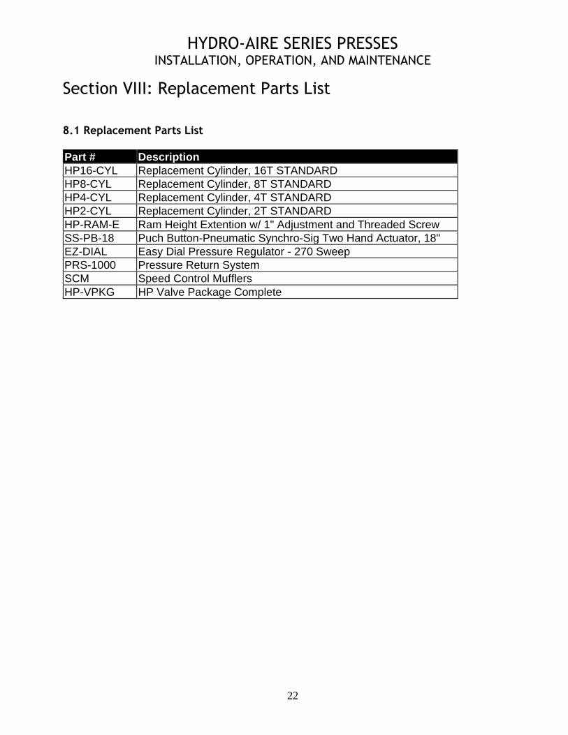
Section VIII: Replacement Parts List 8.1 Replacement Parts List
Part # Description
HP16-CYL Replacement Cylinder, 16T STANDARD
HP8-CYL Replacement Cylinder, 8T STANDARD
HP4-CYL Replacement Cylinder, 4T STANDARD
HP2-CYL Replacement Cylinder, 2T STANDARD
HP-RAM-E Ram Height Extention w/ 1" Adjustment and Threaded Screw
SS-PB-18 Puch Button-Pneumatic Synchro-Sig Two Hand Actuator, 18"
EZ-DIAL Easy Dial Pressure Regulator - 270 Sweep
PRS-1000 Pressure Return System
SCM Speed Control Mufflers
HP-VPKG HP Valve Package Complete
HYDRO-AIRE SERIES PRESSES INSTALLATION, OPERATION, AND MAINTENANCE
23
Factory Support Our 40 year reputation for providing quality TOGGLE-AIRE, DIRECT-AIRE & HYDRO-AIRE presses that meet a wide range of special requirements and our 60 years of service and support experience are all available to you with one phone call. It's your biggest advantage in dealing directly with our factory. Make use of it. Please call with any and all questions you may have regarding your applications and our equipment. Please contact our engineering department to discuss any questions you may have about control systems, modifications, and your applications. We are glad to supply our presses built to your specifications should you require other than our standard systems.
WARRANTY A I M (hereafter referred to as the manufacturer) warrants that all TOGGLE-AIRE & Direct-Aire products will be free from defects in material and workmanship for a period of 180 days from the date of shipment to the original purchaser. Any claim made against this LIMINTED WARRANTY must be made by contacting the customer service department of the manufacturer. At its option, A I M will repair or replace any product it deems defective under the terms of this warranty. If factory service is required, transportation costs to and from the factory are to be paid by the purchaser. This warranty does not apply to equipment that has been subject to abuse, misapplication, negligence, improper maintenance, alteration, or failure to follow manufacturer's instructions. A I M’s, SOLE OBLIGATION UNDER THIS WARRANTY IS STATED ABOVE. THIS WARRANTY IS IN LIEU OF ALL OTHERS, EXPRESSED OR IMPLIED, AND UNDER NO CIRCUMSTANCES WILL A I M BE LIABLE FOR ANY CONSEQUENTIAL DAMAGES RESULTING FROM THE USE OF TOGGLE-AIRE
PRODUCTS.
THINK SAFETY . . . WORK SAFELY . . .
TM TM