Embed Size (px)
Citation preview

Part of Thermo Fisher Scientific
AutoEXEC & AutoPILOT PRO Programmable Logic Controller User GuideP/N 1-0443-071
Revision A


AutoEXEC & AutoPILOT PRO Programmable Logic Controller User GuideP/N 1-0443-071
Revision A

Revision History
Revision Date Description
A 08-2009 Initial release (ERO 7061).
Thermo Fisher Scientific i

This page intentionally left blank.

Table of Contents 1.0 Introduction................................................................................................................. 1
1.1 Data References ................................................................................................ 1 1.2 Registers............................................................................................................ 1 1.3 Accumulator...................................................................................................... 2 1.4 Call Stack.......................................................................................................... 2 1.5 Parameter Stack ................................................................................................ 2 1.6 Timer................................................................................................................. 2
2.0 Source File Structure.................................................................................................. 3 2.1 Declaration Section........................................................................................... 3
2.1.1 $TITLE= ............................................................................................... 3 2.1.2 $WIDTH=............................................................................................. 4 2.1.3 $LENGTH= .......................................................................................... 4 2.1.4 $DECLARE .......................................................................................... 4 2.1.5 $EJECT................................................................................................. 6 2.1.6 $CODESTART..................................................................................... 6
2.2 Code Section ..................................................................................................... 6 2.2.1 Statement Labels................................................................................... 6 2.2.2 Comments ............................................................................................. 6 2.2.3 Executable Statements .......................................................................... 7
3.0 PLC Instruction Set .................................................................................................... 8 3.1 Load/Store Statements ...................................................................................... 9 3.2 Mathematical Statements ................................................................................ 10 3.3 Flow Control Statements................................................................................. 14 3.4 Discrete Control Statements ........................................................................... 16 3.5 Subroutine Control Statements ....................................................................... 16 3.6 Delay Statements ............................................................................................ 17 3.7 Parameter Stack Statements............................................................................ 17
4.0 Using the PLC Compiler .......................................................................................... 20 4.1 Compiler Invocation ....................................................................................... 20 4.2 Compiler Output Files..................................................................................... 22 4.3 Compiler Error Messages ............................................................................... 22
Appendix A – Sample Program........................................................................................... 24
Thermo Fisher Scientific ii

This page intentionally left blank.

1.0 Introduction
This manual provides the information necessary to write a Programmable Logic Controller (PLC) application program, compile the program and generate the downloadable files for execution on the Thermo Scientific AutoEXEC and AutoPILOT PRO RTUs. The Programmable Logic Controller within the AutoEXEC and AutoPILOT PRO RTU allows application programs written in the PLC language to be downloaded and executed within the RTU. Nearly all input/output points within the RTU, both physical and logical, are accessible by the PLC. The PLC instruction set provides for both discrete and floating point operations and includes most transcendental math functions. Subroutine calls are also supported. Memory may be allocated for the storage of both variable and constant data.
1.1 Data References
The PLC uses the internal point numbers of the RTU to identify data items within the flow computer. The PLC program can read or write any data item with a internal point number. A write to any data item that has Audit Logging enabled will result in an audit being generated. Since most data handling/manipulation within the PLC operates on floating point numbers, all data types (discrete, byte, word, etc) will be automatically converted to/from floating point values when read/written by the PLC. For example, reading and loading the PLC accumulator with a discrete value (which is a single bit value of 0 or 1) will cause a floating point value of 0.0 or 1.0 to be loaded. Writing a floating point value to a discrete data item will cause either a 0 (if the floating point value is 0.0) or a 1 (if the floating point value is not 0.0). NOTE: Changing the values of some internal data items within the RTU may result in indeterminate operation.
1.2 Registers
The PLC uses Registers to provide storage for program constants and variables. The AutoEXEC and AutoPILOT PRO RTUs support up to 32 registers in a single PLC program. There is no difference between a register which is used for variable storage or one used for constant storage except for its usage by the program. All registers are assigned an initial value, which can be changed by the program logic.
Thermo Fisher Scientific 1

1.3 Accumulator
The PLC uses an accumulator, which is a floating point value storage location. Nearly all mathematical and comparison instructions operate on the value in the accumulator. As an example, when an “ADD” instruction is executed, the value of the operand is added to the contents of the accumulator and the resultant value replaces the original value of the accumulator. Conditional jump instructions chose their path based upon the result of a comparison between the value in the accumulator and the value of the operand. Some instructions operate only on the contents of the accumulator and require no operand.
1.4 Call Stack
The PLC has an address stack used to save return addresses when subroutines are called. Whenever a “CALL” instruction is executed, the address of the next sequential instruction address is “pushed” on the stack. When a “RETURN” instruction is executed, the last instruction address that was “pushed” is “popped” off of the stack and program execution continues at that address. The PLC stack can hold up to 16 instruction addresses as any one time. If a stack overflow (trying to add to a full stack) or underflow (trying to remove a value from an empty stack) condition is detected, then execution of the program will be halted.
1.5 Parameter Stack
The PLC has a parameter stack that can be used to conveniently hold up to 16 data items. Several PLC instructions are defined for manipulating the data values on the parameter stack. These provide the ability to “PUSH” a data item onto the stack and “POP” a data item from the stack. Additional instructions allow items on the stack to be duplicated, rotated, etc. The parameter stack provides a convenient means to pass parameters to subroutines. If a stack overflow (trying to add data to a full stack) or underflow (trying to remove a value from an empty stack) condition is detected, then execution of the program will be halted.
1.6 Timer
The PLC has an internal timer that may be accessed by the PLC program. This timer is automatically incremented each PLC calculation cycle. The actual value of the increment will be determined by the calculation cycle time of the RTU calculation thread on which the PLC program is executing. A program can read/reset this timer to perform tasks that require the timing of events or processes.
Thermo Fisher Scientific 2

2.0 Source File Structure
The PLC compiler operates on a standard ASCII source file. The file, by default, will have a file extension of “.PLC”. This file can be produced using the text editor incorporated into the compiler, or using an external editor. The source file must contain no imbedded ASCII control characters except for the Tab ( hexadecimal 09), Carriage Return (hexadecimal 0D), Line Feed (hexadecimal 0A) and End-Of-File marker (hexadecimal 1A). The source file is divided into two sections, the Declaration Section and the Code Section. The Declaration Section contains the declarations of data point and registers to be used within the program and compiler control directives. The Code Section contains the PLC instructions.
2.1 Declaration Section
The Declaration Section begins with the first line of the source file and extends to the $CODESTART directive. Any line in the Declaration Section which does not contain a “$” directive is considered to be a comment line. The following is the list of valid “$” directives: Directive Name Function $TITLE= Defines the title string to be output with the listing file $WIDTH= Specifies the listing file page width $LENGTH= Specifies the listing file page length $DECLARE Marks the beginning of a Point or Register declaration $EJECT Causes a Form Feed to be inserted in the listing file $CODESTART Marks the start of the Code Section All directives must be entered exactly as shown above and are case sensitive (must be in capital letters). Any line in the Declaration Section with a “$” is the first non-blank character position which does not match one of the directives will be flagged as an error by the compiler. Directives may be preceded by tabs or spaces.
2.1.1 $TITLE=
The $TITLE' directive allows specification of a title string to be printed at the top of each output page of the listing file. The title includes all characters following the '=' and is terminated by a carriage return. If more then one $TITLE= directive is encountered in the Declaration Section, the last one will be used.
Thermo Fisher Scientific 3

2.1.2 $WIDTH=
The $WIDTH= directive allows specification of the listing file page width. Any lines in the listing file that exceed this width will be wrapped onto the following line. The width may be specified as any value between 50 and 132. If a value smaller then 50 is specified, then 50 will be used. If a value larger then 132 is specified, then 132 will be used. If more then one $WIDTH= directive is encountered in the Declaration Section, the last one will be used. If no width is specified, the width will default to 80.
2.1.3 $LENGTH=
The $LENGTH= directive allows specification of the listing file page length. A form feed will be inserted into the listing file whenever the number of lines on the current page exceeds this length. The length may be specified as any value between 20 and 100. If a value smaller then 20 is specified, 20 will be used. If a value larger then 100 is specified, then 100 is used. If more then one $LENGTH= directive is encountered in the Declaration Section, the last one will be used. If no length is specified, the length will default to 55 lines.
2.1.4 $DECLARE
The $DECLARE directive allows the programmer to declare a text symbol and associate it with a point or register data item that can then be used in the Code Section to reference the item. Symbols are of 2 two types: POINT – Specifies a data item within the flow computer by specifying its AutoEXEC or AutoPILOT PRO Internal Point Number. REGISTER – Specifies a data item declared as a register. Once a symbol has been declared, it may be referenced as an operand in the Code Section. With the exception of certain integer values, only declared symbols may be used as operands in to Code Section. The compiler does not check for or generate errors due to symbol names with multiple declarations, nor does it check the validity of a assigned point number. 2.1.4.1 POINT Declarations A POINT declaration statement has the following format: $DECLARE POINT name Pt# comment Where: Name – Name to be given to the symbol. May be up to 16 characters in length with no embedded spaces. The name is case sensitive. Pt# – This specifies the RTU internal point number to be associated with the
symbol. The Point may be specified in the following formats:
Thermo Fisher Scientific 4

TTT-IIII-FFF TTT = RTU Table Number (1-255) IIII = RTU Item Number (1-8191) FFF = RTU Field Number (1-511)
Examples: 38-2-51 = Table 38 –DP Flow Calculation Item 2 – 2nd DP Meter Run Field 51 – Hourly Flow Rate
If the Pt# field is omitted, then the internal point number will default to 0-0-0. Please refer to the AutoEXEC and AutoPILOT PRO Table Documentation for a list of all internal point numbers.
Comment - (Optional) A Free form comment field terminated with a carriage return. If the Pt# field is omitted, then the comment must be preceded by a semi-colon. At least one space or tab must separate each of the fields. 2.1.4.2 REGISTER Declaration A REGISTER declaration statement has the following format: $DECLARE REGISTER name initial comment Where: Name – Name to be given to the symbol. May be up to 16 characters in length with no embedded spaces. The name is case sensitive. initial – (Optional) This specifies the initial floating point value for the register. If omitted, the initial value defaults to 0.0. The initial
value may be specified and either of the following formats:
Standard - 1234.56 Engineering Unit Notation - 1.23456E3 Comment – (Optional) A Free form comment field terminated with a carriage return. At least one space or tab must separate each of the fields.
Thermo Fisher Scientific 5

2.1.5 $EJECT
The $EJECT directive forces a form feed to be inserted at this point is the listing file. This is the only directive that may also be used in the Code Section.
2.1.6 $CODESTART
The $CODESTART directive marks the beginning of the Code Section and the end of the Declaration Section. Only one of these directives is allowed in a program source file.
2.2 Code Section
The Code Section contains statement labels, comments and executable statements.
2.2.1 Statement Labels
Statement Labels are symbols, which identify PLC program steps for use in Call statements and conditional/unconditional program control statements. The following are two examples: GOTO LABEL1 – Unconditional jump to statement label “LABEL1” JUMP$IF$ZERO LABEL1 – Conditional jump to statement label “LABEL1” if the content of the accumulator is equal to 0.0. The format of a statement label is as follows: Label name: comment Where: Label Name – Name to be given to the label. May be up to 16 characters in length
with no embedded spaces. The name is case sensitive. : – (Colon) Terminates the Statement Label name. Comment – (Optional) A Free form comment field terminated with a carriage
return. No executable statement may appear on a line containing a Statement Label. At least one space or tab must separate each of the fields.
2.2.2 Comments
Comment lines may be inserted anywhere in the Code Section. The format of a comment line is as follows: ; comment
Thermo Fisher Scientific 6

Where: ; – (Semicolon) Identifies the line as a comment line. The semicolon may be preceded by any number of spaces or tabs. Comment – (Optional) A Free form comment field terminated with a carriage Return
2.2.3 Executable Statements
Executable statements are the actual PLC program instructions. The general format of an executable statement is as follows: opcode operand comment Where: opcode – Any valid instruction from the PLC instruction set. The instruction may be preceded by any number of spaces or tabs. operand – (Optional depending upon opcode) This field contains the operand upon which the opcode is to operate. Depending upon the opcode specified, this field may contain a symbol (POINT, REGISTER or statement label), integer number or may be omitted. The operand must be separated from the opcode by at least one space or tab. Comment – (Optional) Free form ASCII comment field terminated by a Carriage return. The comment must be separated from the operand (or opcode if no operand is required) by at least on space or tab.
Thermo Fisher Scientific 7

3.0 PLC Instruction Set
The PLC instruction set includes the following types of instructions: Load/Store – These instructions load the accumulator with a value from a register, Point or Timer or stores the accumulator value to a register or point.
Mathematical – These instructions modify the value of the accumulator or timer by performing some mathematical function (Add, Multiply, Sine, etc).
Flow Control – These instructions alter the program flow either
unconditionally or conditionally based upon a comparison to the accumulator value.
Discrete Control – These instructions provide control of discrete input/output points. Subroutine Control – These instructions provide the ability to call and return from subprograms.
Delay – These instructions allow the program execution to be suspended for designated periods of time.
Parameter Stack – These instructions provide the ability to manipulate the
contents of the PLC Parameter Stack The following sections will describe each PLC instruction in the following format: Name: Operand Types: Accum. Action: Description:
Thermo Fisher Scientific 8

Where: Name: Instruction name. Note: All instruction names are case
sensitive. Operand Types: Lists the valid operand types for the instruction. The Following are the possible types: Point – Symbol name declared as type POINT Register – Symbol name declared as type REGISTER Integer – Integer value Label – Statement Label None – No operand required Accum. Action: Describes the effect of the instruction on the value in the accumulator. Description: Describes the operation performed by the instruction.
3.1 Load/Store Statements
Name: CLEAR$ACC Operand Types: None Accum. Action: Accumulator value set to zero. The current value is lost. Description: This instruction sets the value of the accumulator equal to zero.
Name: LOAD$ACC Operand Types: Point, Register Accum. Action: Replaced with the value of the specified symbol value. The current value is lost. Description: Load the accumulator with the value of the specified Operand.
Name: STORE$ACC Operand Types: Point, Register Accum. Action: Unchanged Description: Stored the current value of the accumulator into specified Operand.
Thermo Fisher Scientific 9

Name: GET$TIMER Operand Types: None Accum. Action: Replaced with the current timer value. The current value is lost. Description: Load the accumulator with the current value of the program Timer. The value is in seconds with 0.1 second resolution.
3.2 Mathematical Statements
Name: INCR$ACC Operand Types: None Accum. Action: Incremented by 1.0. Description: Increment the value in the accumulator by 1.0.
Name: DECR$ACC Operand Types: None Accum. Action: Decremented by 1.0. Description: Decrement the value in the accumulator by 1.0.
Name: INCR$REG Operand Types: Register Accum. Action: Unchanged Description: Increment the value in the specified register by 1.0
Name: DECR$REG Operand Types: Register Accum. Action: Unchanged Description: Decrement the value in the specified register by 1.0.
Name: SQRT Operand Types: None Accum. Action: Value replaced with result. Current value lost. Description: Take the square root of the current accumulator value and store the result in the accumulator.
Name: LOG Operand Types: None Accum. Action: Value replaced with result. Current value lost. Description: Returns the natural logarithm of the current accumulator value and store the result in the accumulator.
Thermo Fisher Scientific 10

Name: EXPONENTIAL Operand Types: None Accum. Action: Value replaced with result. Current value lost. Description: Returns e raised to the power of the current accumulator value and store the result in the accumulator. Name: POWER Operand Types: Register Accum. Action: Value replaced with result. Current value lost. Description: Raise the current accumulator value to the integer power of the value in the specified register and store the result in the accumulator. The value retrieved from the
register is converted to an integer prior to the operation but the actual register contents remain unchanged.
Name: SINE Operand Types: None Accum. Action: Value replaced with result. Current value lost. Description: Returns the sine of the angle specified by the current accumulator value and store the result in the accumulator. The angle must be specified in radians in the range –Pi/2 to +Pi/2.
Name: COSINE Operand Types: None Accum. Action: Value replaced with result. Current value lost. Description: Returns the cosine of the angle specified by the current accumulator value and store the result in the accumulator. The angle must be specified in radians in the range –Pi/2 to +Pi/2.
Name: TANGENT Operand Types: None Accum. Action: Value replaced with result. Current value lost. Description: Returns the tangent of the angle specified by the current accumulator value and store the result in the accumulator. The angle must be specified in radians in the range –Pi/2 to +Pi/2.
Thermo Fisher Scientific 11

Name: ARCTANGENT Operand Types: None Accum. Action: Value replaced with result. Current value lost. Description: Returns the arctangent of the angle specified by the current accumulator value and store the result in the accumulator. The angle must be specified in radians in the range –Pi/2 to +Pi/2.
Name: ADD Operand Types: Point, Register Accum. Action: Value replaced with result. Current value lost. Description: Add the value of the specified symbol to the contents of the accumulator and store the result in the accumulator.
Name: SUBTRACT Operand Types: Point, Register Accum. Action: Value replaced with result. Current value lost. Description: Subtract the value of the specified symbol from the contents of the accumulator and store the result in the accumulator.
Name: MULTIPLY Operand Types: Point, Register Accum. Action: Value replaced with result. Current value lost. Description: Multiply the value of the specified symbol by the contents of the accumulator and store the result in the accumulator.
Name: DIVIDE Operand Types: Point, Register Accum. Action: Value replaced with result. Current value lost. Description: Divide the contents of the accumulator by the value of the specified symbol and store the result in the accumulator.
Thermo Fisher Scientific 12

Name: ADD$TIMER Operand Types: None Accum. Action: Value replaced with result. Current value lost. Description: Add the current value of the Program Timer to the current value of the accumulator and store the result in the accumulator.
Name: SUBTRACT$TIMER Operand Types: None Accum. Action: Value replaced with result. Current value lost. Description: Subtract the current value of the Program Timer from the
current value of the accumulator and store the result in the accumulator. Name: MULTIPLY$TIMER Operand Types: None Accum. Action: Value replaced with result. Current value lost. Description: Multiply the current value of the accumulator by the
current value of the Program Timer and store the result in the accumulator.
Name: DIVIDE$TIMER Operand Types: None Accum. Action: Value replaced with result. Current value lost. Description: Divide the current value of the accumulator by the
current value of the Program Timer and store the result in the accumulator.
Name: RESET$TIMER Operand Types: None Accum. Action: Unchanged Description: Resets the value of the Program Timer to zero.
Name: FIX Operand Types: None Accum. Action: Value replaced with result. Current value lost. Description: Truncate the fractional portion of the current accumulator value and store the whole number result in the
accumulator.
Thermo Fisher Scientific 13

3.3 Flow Control Statements
Name: GOTO Operand Types: Label Accum. Action: Unchanged Description: Make an unconditional jump to the specified statement Label.
Name: JUMP$IF$GE$ZERO Operand Types: Label Accum. Action: Unchanged Description: Jump to the specified Label if the current accumulator value is greater then or equal to zero. Otherwise, execute
the next instruction.
Name: JUMP$IF$LE$ZERO Operand Types: Label Accum. Action: Unchanged Description: Jump to the specified Label if the current accumulator value is less then or equal to zero. Otherwise, execute the
next instruction.
Name: JUMP$IF$GT$ZERO Operand Types: Label Accum. Action: Unchanged Description: Jump to the specified Label if the current accumulator value is greater then zero. Otherwise, execute the next
instruction.
Name: JUMP$IF$ZERO Operand Types: Label Accum. Action: Unchanged Description: Jump to the specified Label if the current accumulator value is equal to zero. Otherwise, execute the next
instruction.
Name: JUMP$IF$NOT$ZERO Operand Types: Label Accum. Action: Unchanged Description: Jump to the specified Label if the current accumulator value is not equal to zero. Otherwise, execute the next instruction.
Thermo Fisher Scientific 14

Name: JUMP$IF$LT$ZERO Operand Types: Label Accum. Action: Unchanged Description: Jump to the specified Label if the current accumulator value is less then zero. Otherwise, execute the next instruction.
Name: IF$GREATER Operand Types: Point, Register Accum. Action: Unchanged Description: If the current accumulator value is greater then the value of the specified symbol then execute the next instruction. Otherwise, skip the next instruction.
Name: IF$EQUAL Operand Types: Point, Register Accum. Action: Unchanged Description: If the current accumulator value is equal to the value of the specified symbol then execute the next instruction. Otherwise, skip the next instruction.
Name: IF$NOT$EQUAL Operand Types: Point, Register Accum. Action: Unchanged Description: If the current accumulator value is not equal to the value of the specified symbol then execute the next instruction. Otherwise, skip the next instruction.
Name: IF$LESS Operand Types: Point, Register Accum. Action: Unchanged Description: If the current accumulator value is less then the value of the specified symbol then execute the next instruction. Otherwise, skip the next instruction.
Name: IF$GT$OR$EQ Operand Types: Point, Register Accum. Action: Unchanged Description: If the current accumulator value is greater then or equal to the current value of the specified symbol then execute the next instruction. Otherwise, skip the next instruction.
Thermo Fisher Scientific 15
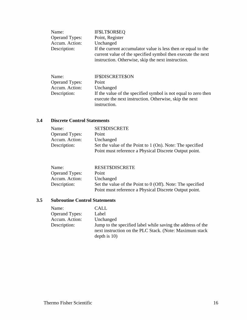
Name: IF$LT$OR$EQ Operand Types: Point, Register Accum. Action: Unchanged Description: If the current accumulator value is less then or equal to the current value of the specified symbol then execute the next instruction. Otherwise, skip the next instruction.
Name: IF$DISCRETE$ON Operand Types: Point Accum. Action: Unchanged Description: If the value of the specified symbol is not equal to zero then execute the next instruction. Otherwise, skip the next instruction.
3.4 Discrete Control Statements
Name: SET$DISCRETE Operand Types: Point Accum. Action: Unchanged Description: Set the value of the Point to 1 (On). Note: The specified Point must reference a Physical Discrete Output point.
Name: RESET$DISCRETE Operand Types: Point Accum. Action: Unchanged Description: Set the value of the Point to 0 (Off). Note: The specified Point must reference a Physical Discrete Output point.
3.5 Subroutine Control Statements
Name: CALL Operand Types: Label Accum. Action: Unchanged Description: Jump to the specified label while saving the address of the next instruction on the PLC Stack. (Note: Maximum stack depth is 10)
Thermo Fisher Scientific 16

Name: RETURN Operand Types: None Accum. Action: Unchanged Description: Pull the instruction address (put there by the most recent CALL instruction) off of the PLC Stack and continue execution at the instruction.
3.6 Delay Statements
Name: DELAY Operand Types: Integer Accum. Action: Unchanged Description: PLC Program execution is halted for the number of 0.1 second intervals specified by the integer value. The maximum integer value is 32767.
Name: DELAY$BY$ACC Operand Types: None Accum. Action: Unchanged Description: PLC Program execution is halted for the number of 0.1 second intervals specified by the current accumulator value. Only the whole number portion of the accumulator value is used. If the current accumulator value is greater then 32767, then 32767 will be used.
Name: PAUSE Operand Types: None Accum. Action: Unchanged Description: The PLC program is suspended until the next execution cycle. This allows other processes within the flow computer to be execute. PLC Program execution will resume automatically.
3.7 Parameter Stack Statements
Name: PUSH$ACC Operand Types: None Accum. Action: Unchanged Stack Size: Incremented Description: The current value of the accumulator is “Pushed” onto the Parameter Stack.
Thermo Fisher Scientific 17

Name: POP$ACC Operand Types: None Accum. Action: Value replaced with the value of the top item on the
Parameter Stack. Current value is lost. Stack Size: Decremented Description: The top item from the Parameter Stack is “Popped” and
stored in the accumulator.
Name: STACK$PUSH Operand Types: Point, Register Accum. Action: Unchanged Stack Size: Incremented Description: The current value of the specified symbol is “Pushed” onto
the Parameter Stack.
Name: STACK$POP Operand Types: Point, Register Accum. Action: Unchanged Stack Size: Decremented Description: The top item from the Parameter Stack is “Popped” and
stored in the specified symbol.
Name: STACK$SWAP Operand Types: None Accum. Action: Unchanged Stack Size: Unchanged Description: The values of the top two positions on the Parameter Stack
are swapped.
Name: STACK$DROP Operand Types: None Accum. Action: Unchanged Stack Size: Decremented Description: The value of the top position on the Parameter Stack is
discarded.
Thermo Fisher Scientific 18

Name: ROTATE$STACK Operand Types: None Accum. Action: Unchanged Stack Size: Unchanged Description: The values of the top three positions on the Parameter
Stack are rotated. The first item on the stack is moved to the second position, the second items on the stack is moved to the third position, and the third item on the stack is moved to the first position.
Name: DUPE$TOP Operand Types: None Accum. Action: Unchanged Stack Size: Incremented Description: A copy of the value of the top position on the Parameter
Stack is pushed onto the top of the stack.
Name: DUPE$SECOND Operand Types: None Accum. Action: Unchanged Stack Size: Incremented Description: A copy of the value of the second position on the Parameter
Stack is pushed onto the top of the stack.
Thermo Fisher Scientific 19
4.0 Using the PLC Compiler
The PLC Compiler allows the programmer to create a new PLC source file or load an existing file from disk (either a .PLC source file or a previously compiled .PLA object file) into the Compiler edit window. The source file can be edited as required and compiled. When the program is compiled, the compiler checks the file for errors and, if none are found, generates three output files, one of which is suitable for loading into the AutoEXEC or AutoPILOT PRO RTU using the Thermo Scientific AutoCONFIG program. The PLC compiler makes three passes through the source file. The first pass interprets the Declaration Section of the program, processing directives and creating a temporary symbol file. The second pass interprets the Code Section of the program checking for valid formatting and instructions. The third pass resolves all symbol references. If no errors were detected during the first three passes, the compiler generates the four output files. If any error are detected during the first three passes, then appropriate errors messages are generated and the compiler aborts processing or the source file at the end of the current pass.
4.1 Compiler Invocation
The PLC Compiler is activated by clicking on the “Compile” menu option. When selected, the PLC program loaded in the Edit Window is sent to the compiler. The output of the compile operation is sent to the Compiler Output Window. When the Compiler is invoked, the following text will be sent to the Compiler Output Window: BEGINNING FIRST PASS If, during first pass processing, errors are detected, the source line containing and error will be sent to the Compiler Output Window with a description of the error detected. Upon completion of the first pass, if errors were detected then the following text will be sent to the Compiler Output Window: FIRST PASS COMPLETED 5 ERRORS DETECTED COMPILATION ABORTED If any error were detected during the first pass, then the compiler operation is halted and the program returns to edit mode. If no errors were detected during the first pass then following text will be sent to the Compiler Output Window: FIRST PASS COMPLETED NO ERRORS DETECTED BEGINNING SECOND PASS
Thermo Fisher Scientific 20

If, during Second pass processing, errors are detected, the source line containing and error will be sent to the Compiler Output Window with a description of the error detected. Upon completion of the Second pass, if errors were detected then the following text will be sent to the Compiler Output Window: SECOND PASS COMPLETED 5 ERRORS DETECTED COMPILATION ABORTED If any error were detected during the second pass, then the compiler operation is halted and the program returns to edit mode. If no errors were detected during the second pass then following text will be sent to the Compiler Output Window: SECOND PASS COMPLETED 0 ERRORS DETECTED BEGINNING THIRD PASS The third pass should always complete without errors unless a file access problem occurs. Upon completion of the third pass, if errors were detected then the following text will be sent to the Compiler Output Window: THIRD PASS COMPLETED 0 ERRORS DETECTED GENERATING LIST FILE The compiler then generates the formatted listing file. When complete, the following text will be sent to the Compiler Output Window: COMPILATION COMPLETED SUCCESSFULLY At this point all files have been successfully generated and the compiler return to the edit mode.
Thermo Fisher Scientific 21

4.2 Compiler Output Files
If no errors are detected during a compile operation, then four output files are created. Each file will have the same name as the PLC source file, but with a different file extension. The output files are identified as follows: Extension File Description .PLA This file contains all of the PLC program instructions (in binary form), initial values for all of the registers and points declared in
the PLC Program. This file is required by the AutoCONFIG program to load the PLC program into the RTU for execution. This file also contains a complete copy of the program source code.
.TBL This file contains an ASCII representation of the .PLR and .PLO files for use by the programmer to debug any program issues. .LST This file contains the formatted output of the compiler formatted as specified by the Declaration Section formatting directives. It includes the source code and some program size information. This file is for programmer use.
4.3 Compiler Error Messages
Error messages may be generated by the compiler as a result of errors in the PLC source code and sent to the Compiler Output Window. The following is a list of the error messages generated by the PLC compiler and a description of the error that causes the message to be generated. Message : ILLEGAL COMMAND CODE DETECTED Cause : During processing of the Declaration Section, a line was found beginning with a “$” that does not contain a valid directive. Message : NO $CODESTART DETECTED Cause : The program source does not contain a $CODESTART directive. Message : ILLEGAL DECLARATION TYPE Cause : The $DECLARE directive does not contain a valid POINT or REGISTER type field. Message : TOO MANY REGISTERS FOR TABLE Cause : The register index exceeds 32.
Thermo Fisher Scientific 22

Message : NO SYMBOL NAME FOUND Cause : The $DECLARE directive contains no symbol name. Message : SYMBOL NAME TOO LONG Cause : The symbol name exceeds 16 characters. Message : COLON WITHOUT A LABEL NAME Cause : The line contains a “:” with no label name. Message : PREMATURE END OF FILE DETECED IN SOURCE FILE Cause : During the second pass processing a premature end of file was detected in the program source. Inspect the source for possible corruption. Message : UNDECLARED SYMBOL Cause : The referenced symbol or statement label has not been declared. Message : ILLEGAL INTEGER (<> 0-32767) Cause : The integer value specified is out of the valid range (0-32767). Message : MISSING SYMBOL Cause : The required symbol is missing. Message : ILLEGAL OPCODE Cause : The opcode specified is not valid. Message : UNIDENTIFIED ERROR Cause : An unidentified file error was encountered. Retry the compiler operation.
Thermo Fisher Scientific 23

Appendix A – Sample Program
The following is a sample PLC Program. $TITLE=Set Minimum Value For Data Point $WIDTH=132 $LENGTH=55 ; ; This program loop executes once per second. It monitors 1 input. ; For the input, If the value >= Low Limit, then the value is copied ; to the output. If the value < Low Limit, then the output is set to ; 0.0 ; ; ;******************************************************************** ;* POINT DECLARATIONS * ;******************************************************************** ; This point is used to enable/disable processing of the PLC Program $DECLARE POINT PLC$ENABLE 2-13-5 ; PLC IN SER $DECLARE POINT INPUT1 16-12-4 ; INPUT VALUE #1 $DECLARE POINT OUTPUT1 1-19-4 ; OUTPUT VALUE #1 ;******************************************************************** ;* REGISTER DECLARATIONS * ;******************************************************************** $DECLARE REGISTER LIMIT1 100.0 ; INPUT #1 VALUE LIMIT $CODESTART ; GIVE THINGS A CHANCE TO SETTLE AND INPUTS TO BE SCANNED DELAY 10 MAIN$LOOP: ; RUN THE LOOP ONCE PER SECOND DELAY 10 ; IF THE PLC IS NOT ENABLED, THEN DON'T DO IT. IF$DISCRETE$ON PLC$ENABLE GOTO PROC$INPUT1 GOTO MAIN$LOOP
Thermo Fisher Scientific 24

Thermo Fisher Scientific 25
PROC$INPUT1: LOAD$ACC INPUT1 IF$LESS LIMIT1 CLEAR$ACC STORE$ACC OUTPUT1 ; ALL DONE, GO BACK TO THE TOP GOTO MAIN$LOOP

This page intentionally left blank.

Thermo Fisher Scientific81 Wyman StreetP.O. Box 9046Waltham, Massachusetts 02454-9046United States
www.thermofisher.com