Embed Size (px)
Citation preview

AutoDome®
and EnviroDome®
Indoor Pendant
In-ceiling Model
Installation ManualVersion 5.3
Security you can rely on
EN

Important Safeguards
1. Read, Follow, and Retain Instructions - All safety andoperating instructions should be read and followed beforeoperating the unit. Retain instructions for future reference.
2. Heed Warnings – Adhere to all warnings on the unit and inthe operating instructions.
3. Attachments - Attachments not recommended by the prod-uct manufacturer should not be used, as they may cause haz-ards.
4. Installation Cautions - Do not place this unit on an unsta-ble stand, tripod, bracket, or mount. The unit may fall, caus-ing serious injury to a person and serious damage to theunit. Use only manufacturer-recommended accessories, orthose sold with the product. Mount the unit per the manu-facturer's instructions. Appliance and cart combinationshould be moved with care. Quick stops, excessive force, oruneven surfaces may cause the appliance and cart combina-tion to overturn.
5. Cleaning - Unplug the unit from the outlet before cleaning.Follow any instructions provided with the unit. Generally,using a damp cloth for cleaning is sufficient. Do not use liq-uid cleaners or aerosol cleaners.
6. Servicing - Do not attempt to service this unit yourself.Opening or removing covers may expose you to dangerousvoltage or other hazards. Refer all servicing to qualified ser-vice personnel.
7. Damage Requiring Service - Unplug the unit from themain AC power source and refer servicing to qualified ser-vice personnel under the following conditions:• When the power supply cord or plug is damaged.• If liquid has been spilled or an object has fallen into the
unit.• If the unit has been exposed to water and/or inclement
weather (rain, snow, etc.).• If the unit does not operate normally, when following the
operating instructions. Adjust only those controls specifiedin the operating instructions. Improper adjustment of othercontrols may result in damage, and require extensive workby a qualified technician to restore the unit to normaloperation.
• If the unit has been dropped or the cabinet damaged.• If the unit exhibits a distinct change in performance, this
indicates that service is needed.8. Replacement Parts - When replacement parts are required,
the service technician should use replacement parts specifiedby the manufacturer, or that have the same characteristics asthe original part. Unauthorized substitutions may result infire, electrical shock, or other hazards.
9. Safety Check - Upon completion of servicing or repairs tothe unit, ask the service technician to perform safety checksto ensure proper operating condition.
10. Power Sources - Operate the unit only from the type ofpower source indicated on the label. If unsure of the type ofpower supply to use, contact your dealer or local powercompany. • For units intended to operate from battery power, refer to
the operating instructions. • For units intended to operate with External Power
Supplies, use only the recommended approved powersupplies.
• For units intended to operate with a limited power source,this power source must comply with EN60950.Substitutions may damage the unit or cause fire or shock.
• For units intended to operate at 24 VAC, normal inputvoltage is 24 VAC. Voltage applied to the unit's powerinput should not exceed 30 VAC. User-supplied wiring,from the 24 VAC supply to unit, must be in compliancewith electrical codes (Class 2 power levels). Do not groundthe 24 VAC supply at the terminals or at the unit's powersupply terminals.
11. Coax Grounding - If an outside cable system is connectedto the unit, ensure that the cable system is grounded. U.S.A.models only--Section 810 of the National Electrical Code,ANSI/NFPA No.70, provides information regarding propergrounding of the mount and supporting structure, groundingof the coax to a discharge unit, size of grounding conductors,location of discharge unit, connection to grounding elec-trodes, and requirements for the grounding electrode.
12. Grounding or Polarization - This unit may be equippedwith a polarized alternating current line plug (a plug withone blade wider than the other). This safety feature allowsthe plug to fit into the power outlet in only one way. Ifunable to insert the plug fully into the outlet, try reversingthe plug. If the plug still fails to fit, contact an electrician toarrange replacement of the obsolete outlet. Do not defeat thesafety purpose of the polarized plug.Alternately, this unit may be equipped with a 3-wire ground-ing plug (a plug with a third pin, for grounding). This safetyfeature allows the plug to fit into a grounding power outletonly. If unable to insert the plug into the outlet, contact anelectrician to arrange replacement of the obsolete outlet. Donot defeat the safety purpose of the grounding plug.
13. Lightning - For added protection during a lightning storm,or when this unit is left unattended and unused for long peri-ods of time, unplug the unit from the wall outlet and discon-nect the cable system. This will prevent damage to the unitdue to lightning and power line surges.
Important SafeguardsEN
© 2005 Bosch Security Systems Page 2 of 36

Safety PrecautionsEN
© 2005 Bosch Security Systems Page 3 of 40
For Indoor Product
1. Water and Moisture - Do not use this unit nearwater - for example, in a wet basement, in anunprotected outdoor installation, or in any areaclassified as a wet location.
2. Object and Liquid Entry - Never push objects ofany kind into this unit through openings, as theymay touch dangerous voltage points or short outparts that could result in a fire or electrical shock.Never spill liquid of any kind on the unit.
3. Power Cord and Power Cord Protection - Forunits intended to operate with 230VAC, 50Hz,the input and output power cord must complywith the latest versions of IEC Publication 227 orIEC Publication 245. Power supply cords should be routed so they arenot likely to be walked on or pinched. Pay partic-ular attention to location of cords and plugs, con-venience receptacles, and the point of exit fromthe appliance.
4. Overloading - Do not overload outlets andextension cords; this can result in a risk of fire orelectrical shock.
For Outdoor Product
Power Lines - An outdoor system should not belocated in the vicinity of overhead power lines,electric lights, or power circuits, or where it maycontact such power lines or circuits. Wheninstalling an outdoor system, extreme care shouldbe taken to keep from touching power lines orcircuits, as this contact might be fatal. U.S.A.models only - refer to the National ElectricalCode Article 820 regarding installation of CATVsystems.
For Rack-Mount Product
1. Ventilation - This unit should not be placed in abuilt-in installation or rack, unless proper ventila-tion is provided, or the manufacturer’s instruc-tions have been adhered to. The equipment mustnot exceed its maximum operating temperaturerequirements.
2. Mechanical Loading - Mounting of the equip-ment in a rack shall be such that a hazardous con-dition is not achieved due to uneven mechanicalloading.
Safety Precautions
Installation should be performed by qualifiedservice personnel only in accordance with theNational Electrical Code or applicable localcodes.
Power Disconnect. Units with or without ON-OFF switches have power supplied to theunit whenever the power cord is inserted into thepower source; however, the unit is operationalonly when the ON-OFF switch is in the ON posi-tion. The power cord is the main power discon-nect for all units.
CAUTION: TO REDUCE THE RISK OF ELEC-
TRIC SHOCK, DO NOT REMOVE COVER (OR
BACK). NO USER SERVICEABLE PARTS
INSIDE. REFER SERVICING TO QUALIFIED
SERVICE PERSONNEL.
This symbol indicates the presence of unin-sulated “dangerous voltage” within the prod-uct’s enclosure that can cause an electricshock.
This symbol indicates the presence ofimportant operating and maintenance (ser-vicing) instructions in the literature accom-panying the appliance.

Safety PrecautionsEN
© 2005 Bosch Security Systems Page 4 of 40
FCC & ICES INFORMATION(U.S.A. and Canadian Models Only)
This device complies with part 15 of the FCC Rules.Operation is subject to the following two conditions:
(1) This device may not cause harmful interference,and
(2) This device must accept any interferencereceived, including interference that may causeundesired operation.
NOTE: This equipment has been tested and found tocomply with the limits for a Class A digital device,pursuant to Part 15 of the FCC Rules and ICES-003 ofIndustry Canada. These limits are designed to providereasonable protection against harmful interferencewhen the equipment is operated in a commercial environment. This equipment generates, uses and radi-ates radio frequency energy, and if not installed andused in accordance with the instruction manual, maycause harmful interference to radio communications.Operation of this equipment in a residential area islikely to cause harmful interference, in which case theuser will be required to correct the interference at hisexpense.Intentional or unintentional changes or modifications,not expressly approved by the party responsible forcompliance, shall not be made. Any such changes or modifications could void the user’s authority tooperate the equipment. If necessary, the user shouldconsult the dealer or an experienced radio/televisiontechnician for corrective action. The user may find the following booklet, prepared bythe Federal Communications Commission, helpful:How to Identify and Resolve Radio-TV InterferenceProblems. This booklet is available from the U.S.Government Printing Office, Washington, DC 20402,Stock No. 004-000-00345-4.
WARNING: This is a Class A product. In a domesticenvironment, this product may cause radio interfer-ence, in which case, the user may be required to takeadequate measures.
Sécurité
Attention : l'installation doit exclusivement être réalisée par du per-sonnel qualifié, conformément au code national d'électricité améri-cain (NEC) ou au code d'électricité local en vigueur.
Coupure de l'alimentation. Qu'ils soient pourvus ou non d'un com-mutateur ON/OFF, tous les appareils reçoivent de l'énergie une foisle cordon branché sur la source d'alimentation. Toutefois, l'appareilne fonctionne réellement que lorsque le commutateur est réglé sur ON. Le débranchement du cordon d'al-imentation permet de couper l'alimentation des appareils.
ATTENTION : POUR ÉVITER TOUT RISQUE D'ÉLECTROCUTION,
N'ESSAYEZ PAS DE RETIRER LE CAPOT (OU LE PANNEAU
ARRIÈRE). CET APPAREIL NE CONTIENT AUCUN COMPOSANT
SUSCEPTIBLE D'ÊTRE RÉPARÉ PAR L'UTILISATEUR. CONFIEZ
LA RÉPARATION DE L'APPAREIL À DU PERSONNEL QUALIFIÉ.
Ce symbole signale que le produit renferme une « tension poten-tiellement dangereuse » non isolée susceptible de provoquer uneélectrocution.
Ce symbole invite l'utilisateur à consulter les instructions d'u-tilisation et d'entretien (dépannage) reprises dans la documen-tation qui accompagne l'appareil.
Sicherheitshinweise
Achtung! Die Installation sollte nur von qualifiziertemKundendienstpersonal gemäß jeweils zutreffenderElektrovorschriften ausgeführt werden.
Unterbrechung des Netzanschlusses. Geräte mit oder ohneNetzschalter haben Spannung am Gerät anliegen, sobald derNetzstecker in die Steckdose gesteckt wird. Das Gerät ist jedochnur betriebsbereit, wenn der Netzschalter (EIN/AUS) auf EINsteht. Wenn das Netzkabel aus der Steckdose gezogen wird, istdie Spannungszuführung zum Gerät vollkommen unterbrochen.
VORSICHT: UM EINEN ELEKTRISCHEN SCHLAG ZU VERMEI-
DEN, IST DIE ABDECKUNG (ODER RÜCKSEITE) NICHT ZU
ENTFERNEN. ES BEFINDEN SICH KEINE TEILE IN DIESEM
BEREICH, DIE VOM BENUTZER GEWARTET WERDEN KÖN-
NEN. LASSEN SIE WARTUNGSARBEITEN NUR VON QUALI-
FIZIERTEM WARTUNGSPERSONAL AUSFÜHREN.
Das Symbol macht auf nicht isolierte „gefährliche Spannung"im Gehäuse aufmerksam. Dies kann zu einem elektrischenSchlag führen.
Der Benutzer sollte sich ausführlich über Anweisungen fürdie Bedienung und Instandhaltung (Wartung) in den begleit-enden Unterlagen informieren.

Safety PrecautionsEN
© 2005 Bosch Security Systems Page 5 of 40
Precauciones de Seguridad
Atención: la instalación la debe realizar únicamente personalcualificado de conformidad con el National Electric Code o lasnormas aplicables en su país.
Desconexión de la alimentación. Las unidades con o sin inter-ruptores de encendido/apagado reciben alimentación eléctricasiempre que el cable de alimentación esté conectado a la fuentede alimentación. Sin embargo, la unidad sólo funciona cuando elinterruptor está en la posición de encendido. El cable de ali-mentación es la principal fuente de desconexión de todas lasunidades.
PRECAUCIÓN: PARA DISMINUIR EL RIESGO DE DESCARGA
ELÉCTRICA, NO RETIRE LA CUBIERTA (NI LA PARTE POSTERI-
OR). NO EXISTEN PIEZAS DE RECAMBIO EN EL INTERIOR
DEL EQUIPO. EL PERSONAL DE SERVICIO CUALIFICADO SE
ENCARGA DE REALIZAR LAS REPARACIONES.
Este símbolo indica que existen puntos de tensión peligrosossin aislamiento dentro de la cubierta de la unidad. Estos pun-tos pueden constituir un riesgo de descarga eléctrica.
El usuario debe consultar las instrucciones de funcionamiento ymantenimiento (reparación) en la documentación que se suminis-tra con el aparato.
Veiligheidsmaatregelen
Attentie: het apparaat mag alleen door gekwalificeerd personeelworden geïnstalleerd. De installatie dient in overeenstemmingmet de nationale elektrische richtlijnen of de van toepassingzijnde lokale richtlijnen te worden uitgevoerd.
Spanning uitschakelen. Apparatuur met of zonder aan-uitschakelaar staat onder spanning zolang de stekker isaangesloten op de wandcontactdoos. De apparatuur is uitsluitendin werking als de aan-uitschakelaar aan staat. Het netsnoer is de"hoofdschakelaar" voor alle apparatuur.
VOORZICHTIG: OPEN DE BEHUIZING OF DE ACHTERKANT
VAN HET APPARAAT NIET. ZO VERMINDERT U HET RISICO
OP ELEKTRISCHE SCHOKKEN. IN HET APPARAAT BEVIN-
DEN ZICH GEEN ONDERDELEN DIE U ZELF KUNT REPAR-
EREN. LAAT SERVICE EN ONDERHOUD UITVOEREN DOOR
GEKWALIFICEERD PERSONEEL.
Dit symbool geeft aan dat er binnen in het apparaat ongeï-soleerde, gevaarlijke spanning aanwezig is die mogelijk elek-trische schokken kan veroorzaken.
De gebruiker dient de bedienings- en onderhoudsvoorschriftente raadplegen in de documentatie die werd meegeleverd methet apparaat.
Sicurezza
Attenzione: l'installazione deve essere effettuata esclusivamenteda personale tecnico qualificato in conformità con il NationalElectrical Code o con le normative locali vigenti.
Scollegamento dell'alimentazione. Le unità dotate o sprovviste diinterruttori ON-OFF vengono alimentate quando si inserisce ilcavo nella presa dell'alimentazione. L'unità è tuttavia in funzionesolo quando l'interruttore ON-OFF si trova nella posizione ON. Ilcavo di alimentazione costituisce il dispositivo di scollegamento del-l'alimentazione principale per tutte le unità.
ATTENZIONE: PER RIDURRE IL RISCHIO DI SCOSSE ELET-
TRICHE NON RIMUOVERE LA COPERTURA (O IL PANNELLO
POSTERIORE). L'UNITÀ NON CONTIENE COMPONENTI
INTERNI RIPARABILI DALL'UTENTE. PER QUALSIASI INTER-
VENTO, RIVOLGERSI A PERSONALE TECNICO QUALIFICATO.
Questo simbolo indica la presenza di "tensione pericolosa" nonisolata all'interno del contenitore del prodotto. Ciò comporta unpotenziale rischio di scosse elettriche.
Si consiglia di consultare le istruzioni operative e di manuten-zione (interventi tecnici) contenute nella documentazione forni-ta con il dispositivo.
Medidas de Segurança
Atenção: a instalação deve ser executada apenas por técnicosqualificados da assistência, de acordo com o código eléctriconacional ou os códigos locais aplicáveis.
Corte de corrente. As unidades com ou sem interruptores ON-OFF (ligar/desligar) recebem corrente sempre que o fio dealimentação está introduzido na fonte de alimentação; contudo, aunidade apenas está operacional quando o interruptor ON-OFFestá na posição ON. O fio de alimentação destina-se a desligar acorrente em todas as unidades.
CUIDADO: PARA REDUZIR O RISCO DE CHOQUE ELÉCTRI-
CO, NÃO RETIRE A TAMPA (OU A PARTE POSTERIOR). NO
INTERIOR, NÃO EXISTEM PEÇAS QUE POSSAM SER
REPARADAS PELO UTILIZADOR. REMETA A ASSISTÊNCIA
PARA OS TÉCNICOS QUALIFICADOS.
Este símbolo indica a presença de "tensão perigosa" não isoladadentro da estrutura do produto, o que pode constituir risco dechoque eléctrico.
O utilizador deve consultar as instruções de funcionamentoe manutenção (assistência) nos documentos que acompan-ham o aparelho.

Safety PrecautionsEN
© 2005 Bosch Security Systems Page 6 of 40
Zasady Bezpieczeƒstwa
Uwaga: Instalacja mo˝e byç wykonywana wy àcznie przez
wykwalifikowanych pracowników obs ugi, zgodnie z zasada-
mi kodeksu National Electrical Code lub innych obowiàzujà-
cych norm.
PRZESTROGA: ABY ZMNIEJSZYå RYZYKO PORA ENIA ELEK-
TRYCZNEGO, NIE NALE˚Y ZDEJMOWAå POKRYWY GÓRNEJ (ani
tylnej). WEWNÑTRZ URZÑDZENIA NIE MA ADNYCH
ELEMENTÓW, KTÓRE MOGÑ BYå NAPRAWIANE SAMODZIELNIE
PRZEZ U˚YTKOWNIKA. SERWIS NALE˚Y ZLECAå WYKWALI-
FIKOWANYM PRACOWNIKOM OBS¸UGI.
Ten symbol wskazuje na obecnoÊç nieizolowanego „niebez-
piecznego napi cia” we wn trzu urzàdzenia. Napi cie to
grozi pora eniem
U ytkownik powinien zapoznaç si z instrukcjami obs ugi
i konserwacji (serwisu), zamieszczonymi w dokumentacji
Od àczanie zasilania Niezale nie od wyposa enia w
wy àcznik zasilania, pràd do urzàdzenia jest
doprowadzany zawsze, gdy przewód zasilania jest
pod àczony do êród a zasilania; jednak urzàdzenie
dzia a tylko wtedy, gdy wy àcznik zasilania jest

EN
© 2005 Bosch Security Systems Page 7 of 40
Table of Contents
SECTION 1
ENVIRODOME AND INDOOR PENDANT INSTALLATION INSTRUCTIONS . . . . . . . . . . . . . . . . . . . .7
SECTION 2
IN-CEILING AUTODOME INSTALLATION INSTRUCTIONS . . . . . . . . . . . . . . . . . . .11
SECTION 3
FASTADDRESS . . . . . . . . . . . . . . . . . . . . . . . . . . . . . . . . . . .13
SECTION 4
AUTODOME SECURITY . . . . . . . . . . . . . . . . . . . . . . . . . .14
SECTION 5
SECTOR BLANKING AND PRIVACY MASKS . . . . . . . . .15
SECTION 6
CHANGING THE BAUD RATE FOR RS-232 OR RS-485 OPERATION. . . . . . . . . . . . . . . . . . . . .16
SECTION 7
ALARMS . . . . . . . . . . . . . . . . . . . . . . . . . . . . . . . . . . . . . . . .17
SECTION 8
AUTOTRACK . . . . . . . . . . . . . . . . . . . . . . . . . . . . . . . . . . . .19
SECTION 9
PELCO PROTOCOL MODE . . . . . . . . . . . . . . . . . . . . . . . .20
SECTION 10
MAINTENANCE/COMPONENT REPLACEMENT . . . . . . . . . . . . . . . . . . . . . . . . . . . . . . . . . .23
SECTION 11
TROUBLESHOOTING GUIDE . . . . . . . . . . . . . . . . . . . . .24
SECTION 12
AUTODOME LOCKED COMMANDS . . . . . . . . . . . . . . .26
SECTION 13
ADVANCED MENU . . . . . . . . . . . . . . . . . . . . . . . . . . . . . . .27
APPENDIX A
POWER WIRING GUIDE . . . . . . . . . . . . . . . . . . . . . . . . . .34
APPENDIX B
OPTIONAL GASKET INSTALLATION . . . . . . . . . . . . . . .35
AUTODOME USER MANUAL (Insert) . . . . . . . . . . . . . . . .36AUTODOME USER COMMANDS (Unlocked Commands) . . . . . . . . . . . . . . . . . . . . . . . . . . . .39
NOTE: Before beginning installation, please remove the USERMANUAL in the back of this booklet.
SECTION 1
EnviroDome and Indoor Pendant
Installation Instructions
Camera Addressing
1.1 To use FastAddress, skip to STEP 1F. Otherwise, to manually set the switch address, position the dome on thestar shaped foam, with the bubble side down.
Photo 1A Position dome
1.2 Remove the 4 top screws as shown in PHOTO 1B, and liftthe top plate carefully off the dome. The cable length isapproximately 5 cm (2 in), so remove carefully from thePCB.
Remove the top plate cable (if necessary) from the dometo access the address switch. Set the address switch (as inSTEP 1C) and make a note of it.
Photo 1B Remove screws
1.3 If using RS-232/RS-485 Communications:
The unit is shipped with the Baud Rate set to 9600. Thebaud rate may be changed via the COMMUNICATIONSSETUP menu (see SECTION 6).
Introduction

EN
© 2005 Bosch Security Systems Page 8 of 40
The following dip switch settings pertain to AutoDomeVersions 5.00 and newer.
*Default position for all switch settings is OFF.Figure 1A S105 Dip Switch Settings
Photo 1C Set the address switch
1.4 Reconnect the top plate cable, then replace the top plateand gasket (see PHOTO 1D). Align the ribs on the bot-tom of the top plate with the matching openings in thehousing, then firmly tighten the four (4) screws.
Photo 1D Replace top plate
1.5 To avoid confusion during installation, write the cameraaddress on masking tape and stick it to the dome, asshown in PHOTO 1E.
The dome is now ready to be installed, using an appropriate AutoDome mount.
Photo 1E Write camera address
Installation should be performed by qualified servicepersonnel only, in accordance with the NationalElectrical Code or applicable local codes. Refer to theappropriate installation section.
The AutoDome can be mounted to a wall, mast (pole), roof,pipe, or a corner mount once the appropriate mount has beeninstalled. Each mount includes its own mounting instructions.
Mounts must be properly and securely mounted to asupporting structure capable of sustaining the unitweight.**Use care when selecting mounting hardware(not supplied) for installation. The mounting surfaceand unit's weight should be carefully considered.
The following instructions reference a 120/230 VAC pendant wall plate installation mounted to an existing structure.The instructions assume the safety cable, power, video, and con-trol cables have already been properly installed.
**Refer to mounting instructions.
Section 1
Switch # Function Position Selection
1 RESERVED
2 Serial Mode SelectionON
OFF
RS-485
RS-232*
3 RESERVED
4 Low Pressure DetectionON
OFF
Pressurized Dome
Non-Pressurized
Dome*
AddressSwitches
S105 Dip Switches

EN
© 2005 Bosch Security Systems Page 9 of 40
1.6 Attach the installation-assist cable* to the eyehook on thetop of the dome, and close the safety cable (see PHOTO1F).
* A cable (user-provided) is recommended for safety purposes when pipe mounting. See Mounting Guide forinstructions.
Photo 1F Connections
1.7 MAKE THE FOLLOWING CONNECTIONS:
**If the AutoDome is programmed for RS-485 operation, RXDfunctions as DATA (+), and TXD functions as DATA (–).
Figure 1B Control connector
a. If the Alarm Inputs or the Relay Output are beingused, connect the appropriate wires to the 8-pin Alarmconnector (see FIGURE 1C).
Figure 1C Alarm connector
b. Connect Video (BNC) cable and the CONTROL connector. Tighten screws on control connector.
c. When using Biphase, and the dome is in a starconfiguration (or is the last dome on a daisy chain), itrequires a 110 Ω terminating resistor (included) acrosspin 8 (C+) and pin 9 (C–).
Daisy chain configuration is not possible if fiber opticaccessory is used.
1.8 AUTODOME 24 VAC INSTRUCTIONS ENVX2450X, ENVX2460X, G3AX5X, and G3AX6X Kits
Check for the following:
a. An ENV-PSU (or equivalent) power supply must beused.
b. Be sure to use an adequate gauge of 24 VAC wiring forthe distance run. See APPENDIX A - Power WiringGuide for proper wiring instructions and recommendedwire run lengths.
c. Wire the 9-pin CONTROL connector located on thetop of the unit, as in STEP 1G.
d. If the Alarm Inputs or Relay Output are being used,connect the appropriate wires to the 8-pin Alarmconnector.
Figure 1D
If not using an ENV-PSU, place a jumper between Pin (1) 24 VAC Hot and Pin (3) Heater (see APPENDIX A for details).
1.9 Align the notch on the AutoDome with the notch on theFRONT of the Pendant Arm.
Section 1
GND A1 A2 A3 A4 NC COM NO
8 7 6 5 4 3 2 1
ALARM CONNECTOR
ALARM GROUND
ALARM INPUT #1
ALARM INPUT #2
ALARM INPUT #3
NORMALLY OPEN
RETAINING SCREW
RELAY COMMON
NORMALLY CLOSED
ALARM INPUT #4
C–
Biphase GroundBiphase +Biphase –
RS-232 Ground
**RS-232 TX**RS-232 RX
24 VAC Neutral
Indoor Pendant - Not ConnectedEnviroDome® - 24 VAC Heater
24 VAC Hot
C+ GND RXD TXD GND H 24 VAC
9 8 7 6 5 4 3 2 1
CONTROL CONNECTOR
Retaining Screw
BNC Connector
Eyehook
8-Pin AlarmConnector 9-Pin Control
Connector
Installation Assist Cable
**EnviroDome Only
Top of Dome
(1) 24 VAC Hot
(2) 24 VAC Neutral
(3) Heater**
(4) RS-232 Ground
(5) RS-232 TXD
(6) RS-232 RXD
(7) Biphase Ground
(8) Biphase +
(9) Biphase –
To ENV-PSU
or
equivalent

EN
© 2005 Bosch Security Systems Page 10 of 40
Lift the AutoDome into the Pendant Arm and twist untilthe notch on the AutoDome is aligned with the notch onthe SIDE of the pendant arm.
Photo 1G Align notches
1.10 Tighten the two screws on the top of the pendant arm until snug.
Photo 1H Tighten screws
Some models require a slotted screw instead of an Allen screw.
Apply power to the AutoDome.
1.11 If using the FastAddress feature, see SECTION 3 for additional information.
Congratulations! You’ve installed the AutoDome.
Photo 1I Installed AutoDome
Section 1
ALIGN NOTCHES
ROTATE

EN
© 2005 Bosch Security Systems Page 11 of 40
SECTION 2
In-ceiling AutoDome
Installation Instructions
2.1 Before installing this unit, install and wire the In-ceiling Backbox (LTC 7490), following the instructionsprovided with that unit.
Carefully remove the AutoDome from the box. Save allpacking material, to be used for setup and transport ofthe camera and dome.
If an item appears to have been damaged in shipment,notify the shipper. If any items are missing, notify yourBosch Sales or Customer Service Representative at the location nearest you. See our Web site at www.boschsecurity.com.
Photo 2A In-ceiling AutoDome
2.2 To use FastAddress, skip to STEP 2C. Otherwise, set theaddress switch as shown. Setting address selector to 0000causes the AutoDome to respond to ALL messages regardlessof address (NOT RECOMMENDED); otherwise, the unitonly responds to commands issued for that address.
If using RS-232/RS-485 Communications:
The unit is shipped with the RS-232/RS-485 Baud Rateset to 9600. This rate can be changed via theCOMMUNICATIONS SETUP menu (see SECTION 6).
The following settings pertain to AutoDome versions 5.00and newer:
*Default position for all switch settings is OFF.Figure 2A S105 Dip Switch Settings
Photo 2B S105 Dip switch and Address selector
Section 2
Switch # Function Position Selection
1 RESERVED
2 Serial Mode SelectionON
OFF
RS-485
RS-232*
3 RESERVED
4 Low Pressure DetectionON
OFF
Pressurized Dome
Non-Pressurized
Dome*
S105 Dip SwitchAddress Switch

EN
© 2005 Bosch Security Systems Page 12 of 40
2.3 Attach the dome window to the camera module, aligningthe blue LOCK labels.
Snap the dome cover into position by pressing gently on the dome 90° from the blue labels.
Photo 2C Attach dome window
2.4 While holding the top of the camera, rotate the lowerportion and align the camera dome yellow markers.
Photo 2D Align yellow markers
2.5 With the red dot on the camera module facing the reddot on the backbox, slide the camera module into thebackbox module using the guides. Note that the camera isshown turned 180 degrees to illustrate red markers.
Photo 2E Align red markers
2.6 While grasping the unit by the dome window, insert thecamera module completely into the backbox.
Photo 2F Insert camera module
2.7 While pressing up, twist the dome window/locking ringclockwise approximately 1/4 turn. The camera will initialize ten seconds after it is properly installed.
Photo 2G Lock dome into place
2.8 An optional tamper clip is provided to prevent the domefrom being removed. To install, locate the blue label,orient the tamper clip with the two tabs pointing up, andpress the tamper clip into the locking ring just to theright of either blue label. A straight blade screwdriverwill help push the clip in place.
Section 2
BLUELABEL
90°
90°
YELLOWMARKERS
REDMARKERS
RED DOTSFACING EACH
OTHER
TURN TOLOCK

EN
© 2005 Bosch Security Systems Page 13 of 40
Photo 2H Optional tamper clip
2.9 To install the trim ring, align the yellow dots on theinside of the trim ring with the yellow dots on the lockingring. To ensure proper installation, push on the trim ringvertically until a click is felt. Installation is now complete.
If using the FastAddress feature, see SECTION 3 for additional information.
2.10 INSTALLATION
Installation should be performed by qualified servicepersonnel only, in accordance with the NationalElectrical Code or applicable local codes.
The AutoDome system is suitable for use in environmental airspaces or in an air handling plenum of a nonfire-resistant ceiling.
Do not remove camera from pan/tilt. Remove the entirereceiver/driver, pan/tilt, and camera assembly from theAutoDome system to prevent damage to the flexible cable and connector.
SECTION 3
FastAddressThe FastAddress feature allows the AutoDome’s cameras to beaddressed (or the address may be changed) via a keyboard andon-screen menus instead of using the switch address (thumb-wheel). If FastAddress is not used, the camera’s address defaultsto the address indicated by the thumbwheel switches.Conversely, if FastAddress has been programmed, the thumbwheel switches are ignored.
There are two commands used to address the AutoDome via theFastAddress feature:
• ON-999-ENTER: All domes that have not already been configured using FastAddress will respond to this command.Additionally, if the address of a previously configured domematches the camera number at the keyboard, that dome willrespond to the command as well.
• ON-998-ENTER: All domes respond to this command,regardless of FastAddress status.
NOTE: In systems with multiple monitors, other domes mayalso enter the FastAddress mode. As commands (which areunique for each dome) are entered, the other domes automatically exit the FastAdress mode, and only the targetdome remains active. Following are some instances whenFastAddress would be used:
1. New or existing installation of an AutoDome(s):
a. Set the keyboard to display the camera, for example,CAMERA-3-ENTER (where 3 is the camera whoseaddress you’re identifying/changing).
b. Press ON-999-ENTER, and follow the instructions on thescreen (see FIGURE 3A).
REMINDER: All domes that have not already been configured using FastAddress will respond to ON-999-ENTER.
c. When a camera is being moved, the dome may already have an address, therefore it will not respond toON-999-ENTER. In this case, you must use ON-998-ENTER to readdress the camera, then follow theon-screen instructions.
d. There is a visual confirmation that the address was set.
2. Clearing the address of a camera (causing the address of thecamera to revert back to the address set by the thumbwheel):
a. Enter FastAddress mode using either method describedabove, then follow the on-screen instructions (see FIGURE 3B).
b. At the end of FastAdress mode, press OFF-1-ENTER toclear the address.
Section 3

EN
© 2005 Bosch Security Systems Page 14 of 40
c. There is a visual confirmation that the address was cleared.Use ON-997-ENTER to check/confirm camera addresses.For example, if referring to Camera 3, press CAMERA-3-ENTER, then ON-997-ENTER. This causes allcameras to briefly display their addresses.
FastAddress is stored to nonvolatile memory, thus will not changeif power is removed or factory defaults are restored (SET-899-ENTER).
Figure 3A Enter new address
Figure 3B Clearing address
SECTION 4
AutoDome SECURITY
The AutoDome has password protection capability forAdvanced Menu access and other locked commands.
To set a password, after entering OFF-90-ENTER, enterSET-802-ENTER and follow the on-screen instructions to set orchange the password. Passwords are four (4) digits in length andare selected via the joystick.
The AutoDome's default password of 0000 <four zeros> allowsOFF-90-ENTER to directly unlock the Advanced Menu commands. If the password of 9999 is used, the AutoDome istotally unlocked so that all AutoDome commands can be executed (no OFF-90-ENTER is required to use ADVANCEDCOMMANDS).
If any other 4-digit password is set, the AutoDome prompts forentry of a password when the unlock command,OFF-90-ENTER, is entered.
Section 4

EN
© 2005 Bosch Security Systems Page 15 of 40
SECTION 5
SECTOR BLANKING AND PRIVACY MASKS
SECTOR BLANKING simply blanks allvideo in a specified sector. Sectors aredefined as 1/16 of the total 360° field-of-view. Any combination of these sectors canbe blanked via the BLANKING MENU,ON-86-ENTER.
PRIVACY MASKS give the installer theopportunity to black out (mask) areas from visibility. Up to six (6)rectangular Privacy Masks can be defined. These masks changelocation and size as the camera pans, tilts and zooms.
When entering the PRIVACY MASKING screen (ON-87-ENTER), a list of masks is displayed for on-screenselection. An * at the front of the line indicates that the mask iscurrently occupied, and if selected, the mask will be overwrit-ten. The first available (unused) Privacy Mask is indicated by anarrow at the left margin, as shown below in FIGURE 5A.
Figure 5A Privacy Masking menu
Use the joystick to scroll through the list of masks until the desiredmask is highlighted.
While in the PRIVACY MASKING menu, the following commands are available:
• FOCUS+ draws a new Privacy Mask (or edits an existingmask). A 1x1 block is drawn in the center of the screen (asshown in FIGURE 5B).
• FOCUS– deletes the selected mask (and removes the *, signifying that the mask is now unused).
• IRIS+ moves the AutoDome so that the highlighted mask is centered on the screen.
• IRIS– exits the menu.
TO CREATE A MASK:
1. First, use the joystick to maneuver to the area to be masked,then zoom in so that this area is between 25% to 50% ofthe total screen.
2. Press ON-87-ENTER to enter the menu (as shown in FIGURE 5A). Use the joystick to scroll through the list ofmasks until the desired mask is highlighted. Press Focus+to edit this mask.
3. If desired, use the joystick to adjust the area to be masked.Pan, Tilt, and Zoom are all available to reposition thecamera to the view that is to be masked. Press FOCUS tocontinue (as shown in FIGURE 5B).
Figure 5B Reposition Camera
4. Use the joystick to move the masking block to the center ofthe area to be masked. Press either FOCUS button toanchor the mask (as shown in FIGURE 5C).
Figure 5C Move Block
5. Use the joystick to modify the mask's dimensions by movingto the right and down. Ensure that the mask is larger than theobject/area to be masked (as shown in FIGURE 5D).
Figure 5D Modify Mask
Section 5
1
2
3
45
78
9
10
11
1213 14 15 16
6

EN
© 2005 Bosch Security Systems Page 16 of 40
6. Press FOCUS again to continue. The AutoDome nowadjusts its zoom position and allows fine-tuning of themask coverage by using the joystick. FIGURE 5E shows asample mask.
Figure 5E Adjusts Mask
7. When finished fine-tuning the mask, press either IRIS button to exit the menu and save the current mask. Verifysufficient mask coverage by panning, tilting and zoomingthrough the field-of-view.
SECTION 6
CHANGING THE COMMUNICATION SETUP FOR RS-232, RS-485 OR Bilinx™
If RS-232 or RS-485 is used to control the AutoDome, the baudrate may be changed via the following steps:
1. View the video from the camera on a monitor. Using anappropriate controller/keyboard, unlock the AutoDomemenus using OFF-90-ENTER.COMMAND: UNLOCKED should briefly appear at thetop of the monitor.
2. Enter the Setup menu using ON-46-ENTER. The mainSetup menu should appear, as follows:
Figure 6A Camera Setup
3. Use the joystick to move down to the CommunicationSetup menu and press FOCUS on the controller/key-board.
Figure 6B Communication Setup
4. Press and release FOCUS until the desired baud rateappears. Then press IRIS to SAVE and EXIT.
5. A countdown message will appear to confirm the baudrate change. If the baud rate of the controller is changedwithin 60 seconds, and the joystick is moved in any direc-tion, the baud rate will be saved and made active. If thejoystick is not moved at all, the AutoDome will discardthe change and revert back to the previous baud rate.
Figure 6C Baud Rate Confirmation
Versions 5.10 and higher of the AutoDome can also communi-
cate directly through the coax using BILINX. The BILINX data
communications may be disabled by changing the menu selec-
tion to OFF.
1. Use the joystick to move down to the BILINX selection
and press FOCUS on the controller/keyboard. The
selection will change to OFF, and the BILINX data will be
disabled.
2. Press IRIS to SAVE and EXIT.
NOTE: For more information on how BILINX may be used to
configure the camera, refer to the Configuration Tool software.
P/N VP-CFGSFT.
Section 6

EN
© 2005 Bosch Security Systems Page 17 of 40
SECTION 7
ALARMS
7.1 Inputs
There are four (4) Alarm Inputs that may be activated by a drycontact input closure. The alarm conditions must be present forgreater than 200 ms to be recognized as a valid alarm. Eachalarm input may be individually programmed for the type anddesired Action to occur when an alarm is received (as shown inFIGURE 7A). The choices available are listed in FIGURE 12F inthe back of this manual, and are explained in the AdvancedMenu, SECTION 12.
Figure 7A Input Setup Menu
The most important actions are GO TO SHOT and the OSDdisplay. The camera may be programmed to go to any preprogrammed shot from 0 to 99. If 0 is entered as the SHOTnumber, the camera simply flashes the word ALARM on themonitor, but will not move from the current position (seePHOTO 7A).
Photo 7A Alarm active
The OSD may be turned OFF, and then the camera will move tothe shot, but will not flash the word ALARM. To acknowledgean ALARM and turn off the flashing display, use the auxiliarycommand OFF-65-ENTER on a Bosch controller/keyboard. TheALARM message will be removed from the monitor, but if thecontact closure is still activated, an "A" will appear in the topright-hand corner of the monitor, as shown in PHOTO 7B.When the contact input changes back to a non-alarm state, the"A" will be removed.
Photo 7B Alarm Acknowledged but still active
7.2 Low Pressure Alarm
The pressurized version of the AutoDome has an internal low-pressure sensor that is prewired to Alarm Input # 4. If the inter-nal pressure is lost, the sensor activates the ALARM input, andinstead of the word ALARM being displayed, the word PRESSURE will flash on the display, as shown in PHOTO 7C.
Photo 7C Low Pressure Alarm
Section 7

EN
© 2005 Bosch Security Systems Page 18 of 40
When the pressure alarm is acknowledged using OFF-65-ENTER, the flashing display will stop, but the letter "P"will appear in the top right-hand corner of the monitor(PHOTO 7D). This AutoDome will continue to display thiswarning until the low-pressure problem has been corrected.
Photo 7D Low Pressure Alarm continued
7.3 Alarm Relay Output
The alarm relay output may be activated either manually, ortriggered when an Alarm occurs. There are three possible choices for the time period that the relay output will remainactivated. These choices are:
1 Follow input: This means it mimics the state of the alarm.As long as the alarm is active, the relay will be energized.
2 Latched: The relay will energize upon an alarm, and willremain energized until the user issues the commandOFF-65-ENTER twice. The first time acknowledges thealarm and removes the OSD (if programmed to display),and the second time clears the alarm and resets the relay.
3 Specific length of time. This can be anywhere from one sec to ten min. An OFF-65-ENTER that's enteredtwice will again deactivate the relay, even if the timer hasnot yet expired.
These choices are also listed in the Advanced Menu,SECTION 12.
To manually activate the relay output from a Boschcontroller/keyboard, use the sequence of ON-65-ENTER. UseOFF-65-ENTER to deactivate it.
The function of OFF–65-ENTER is different when the triggerfor the relay output is an alarm input. When the alarm input isactivated, the relay output will also be activated immediately.When the alarm is acknowledged by OFF-65-ENTER, the firsttime, the relay output will NOT deactivate. It will remain on forthe period selected in the menu. However, if OFF-65-ENTER isentered a second time, the relay output will deactivate immedi-ately, no matter what time period is set in the menu. This acts asan alarm override, but the relay output will not activate againuntil the Alarm has been cleared and another alarm occurs.
Example: Alarm 1 is set to be NORMALLY OPEN,GO TO SHOT 1, OSD ON, and the output is set to be triggered by Input 1 for a time period of 1 min, and is connected to the Alarm Input of a digital recorder (DVR).
When the external contact is closed, the AutoDome will moveto SHOT 1, flash the word ALARM on the display, and activatethe relay output so the digital recorder starts recording. PressingOFF-65-ENTER would clear the flashing display and change tothe letter "A" in the upper right-hand corner, but the relay out-put will still be on and the DVR still recording. After 30 sec, thealarm input is still active, but if OFF-65-ENTER is pressedagain, the relay output will turn off and the DVR will stoprecording. The "A" is displayed until the alarm contact changesstate.
Section 7
Low Pressure
EN
© 2005 Bosch Security Systems Page 19 of 40
SECTION 8
AutoTrack
WHAT IS AutoTrack?
The AutoTrack feature is a motion detector, which takes overPTZ control of the Dome. The user always has the ability tomanually override by simply moving the joystick. It is sensitiveto motion of all kinds, and should only be used in the sameapplications that a standard motion detector would be; any-where there is little or no motion expected. It may be used inconjunction with a preset tour, or a recorded guard tour thattakes periodical pauses of at least two sec during the tour. It canalso be used when the dome is static (stationary in one posi-tion).
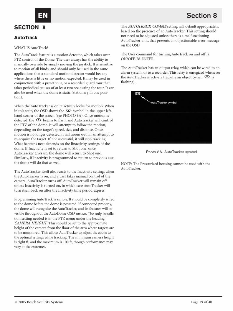
When the AutoTracker is on, it actively looks for motion. Whenin this state, the OSD shows the symbol in the upper left-hand corner of the screen (see PHOTO 8A). Once motion isdetected, the begins to flash, and AutoTracker will controlthe PTZ of the dome. It will attempt to follow the motion,depending on the target’s speed, size, and distance. Oncemotion is no longer detected, it will zoom out, in an attempt tore-acquire the target. If not successful, it will stop tracking.What happens next depends on the Iinactivity settings of thedome. If Inactivity is set to return to Shot one, onceAutoTracker gives up, the dome will return to Shot one.Similarly, if Inactivity is programmed to return to previous aux,the dome will do that as well.
The AutoTracker itself also reacts to the Inactivity setting; whenthe AutoTracker is on, and a user takes manual control of thecamera, AutoTracker turns off. AutoTracker will remain offunless Inactivity is turned on, in which case AutoTracker willturn itself back on after the Inactivity time period expires.
Programming AutoTrack is simple. It should be completely wiredto the dome before the dome is powered. If connected properly,the dome will recognize the AutoTracker, and its features will bevisible throughout the AutoDome OSD menus. The only installa-tion setting needed is in the PTZ menu under the headingCAMERA HEIGHT. This should be set to the approximateheight of the camera from the floor of the area where targets areto be monitored. This allows AutoTracker to adjust the zoom tothe optimal settings while tracking. The minimum camera heightis eight ft, and the maximum is 100 ft, though performance mayvary at the extremes.
The AUTOTRACK COMMS setting will default appropriately,based on the presence of an AutoTracker. This setting shouldnot need to be adjusted unless there is a malfunctioningAutoTracker unit, that presents an objectionable error messageon the OSD.
The User command for turning AutoTrack on and off isON/OFF-78-ENTER.
The AutoTracker has an output relay, which can be wired to analarm system, or to a recorder. This relay is energized wheneverthe AutoTracker is actively tracking an object (when isflashing).
Photo 8A AutoTracker symbol
NOTE: The Pressurized housing cannot be used with theAutoTracker.
Section 8
AutoTracker symbol
SECTION 9
PELCO PROTOCOL MODE
9.1 Description
The Pelco Protocol Mode provides support for Pelco-P andPelco-D protocols, and is incorporated in AutoDome firmwareversion 5.31 and higher. It features Auto Baud Detection whichautomatically detects and adjusts the AutoDome protocol andbaud rate to match the controller’s.
9.2 Hardware Configuration
9.3 RS-485 Setup
To use the Pelco Protocol Mode, the AutoDome must be configured for RS-485 operation.
1. Set the AutoDome configuration dipswitch #2 to ON. SeeSECTION 1 and SECTION 2.
2. Connect the RS-422 controller Tx+ terminal to theAutoDome’s RxD terminal.
3. Connect the controller’s Tx- terminal to the AutoDome’sTxD terminal. See SECTION 1 and SECTION 2.
Both the Pelco controller and AutoDome must be configuredbefore connecting the devices together. The AutoDome willrespond to Bosch OSRD, Pelco-D, and Pelco-P commands.
The Pelco Mode only supports RS-485 protocol. It will not transmit reponses to commands it receives.
9.4 Set Addresses
• Addresses 0 to 9998 are available for Bosch OSRD commands.
• An AutoDome with an address set to 0 will respond tocommands sent to any address.
• Pelco-P protocol must use addresses 1-to-32.
• Pelco-D protocol must use addresses 1-to-254.
An AutoDome that was previously configured with anaddress above 32 (Pelco-P upper limit) or 254 (Pelco-Dupper limit) can be used without re-addressing theunit. However, care must be taken that no twoaddresses are repeated.
For example:Pelco-P addresses above 32 are repeated in multiples of32 (1, 33, 65, 97 are the same).
Pelco-D address above 254 are repeated in multiples of254 (1, 255, 509, 763 are the same).
9.5 Software
AutoDome firmware 5.31 or higher must be installed for Pelco pro-tocol mode to operate. Procedures for uploading a new AutoDomefirmware must be followed to successfully install an upgrade.
Only a Bosch VP-CFGSFT firmware upload tool (soldseperately) can be used to install a firmware upgrade tothe AutoDome.
9.6 Commands
The Pelco Set-Preset command is used by AutoDome to setPresets 1 through 99. Some Presets have special meaning andoverride the normal preset function as follow:
Special Preset CommandsSET A PRESET To set a Preset press and hold the
[PRESET] button for 2 seconds.
92-PRESET Sets the Left Pan limit for an AutoScanwith Limit Stops enabled.
93-PRESET Sets the Right Pan limit for an AutoScanwith Limit Stops enabled.
95-PRESET Invokes the Setup Menu.
GO TO A PRESET To go to a Preset momentarily press andrelease the [PRESET] button.
33-PRESET Pans the AutoDome 180 degrees (Flip).
34-PRESET Goes to Zero Pan.
94-PRESET Initiates a Preset Tour
96-PRESET Stops a scan.
97-PRESET Initiates FastAddress (Pelco RandomScan)
98-PRESET Toggles the Sync Mode between LineLock and Crystal (Pelco Frame Scan).This command is only accessible for 2 minutes after power is applied and then reverts to normal Preset functionality.
99-PRESET Start an AutoScan. (User can enable ordisable Limit Stops in the Setup Menufor AutoScan.)
Some Pelco controllers do not support all Preset numbers. Consult the specific Pelco controller’s documentation for supported Presets.
Section 9EN
© 2005 Bosch Security Systems Page 20 of 40

9.7 Menu
To access the dome’s main Setup Menu enter 95-[PRESET].AutoDome will display a list of configuration items. Somemenu items can be locked and require a system password toaccess. The Bosch Menu item provides full access to theAutoDome menus.
9.8 Preset Titles
Preset titles can be added, removed, or changed through themain Setup Menu through the Edit Presets menu item.
Some Pelco preset titles can be 20 characters long;however AutoDome only supports 16 characters andwill drop the last 4.
9.9 Patterns
Pelco Patterns or recordings are supported. The AutoDome supports patterns 1 and 2.
1. To start recording a Pattern, enter #[PATTERN] wherethe number specifies which of the 2 supported patterns to record.
2. The command to stop a pattern varies among different Pelco controllers. Consult the specific Pelco controller’sdocumentation for information on setting Patterns.
3. To playback a recorded Pattern, select the desired patternnumber and momentarily press (do not hold) the [PATTERN] key. The user can stop the playback by sending any PTZ, focus, or iris command.
9.10 Preset Tour
The AutoDome can be programmed to execute a Preset Tourwith adjustable dwell times. To start a tour, the Pattern 3command must be sent from the Pelco controller by entering 3-[PATTERN]. Consult the specific Pelco controller’s documentation for information on setting Patterns.
Dwell time can be adjusted by entering 95-[PRESET] to enterthe main Setup Menu and then selecting the Tour Period menuitem. Presets to include on a tour can also be added or deletedthrough the Edit Tour menu item.
9.11 95-PRESET Menu
When a 95-[PRESET] command is sent from a Pelco controldevice, the AutoDome displays the main Setup Menu.Following are the menu items and a brief description:
Bosch Menu… (Locked) Accesses the full AutoDome con-figuration menu and all AutoDome settings.
Command Lock: (Locked) Allows/Disallows (ON/OFF)locked commands to be accessed.
Edit Password: (Locked) Sets or displays password. SeeAuto Dome Security, SECTION 4 fordetails. (Must enter password to unlockmenu even if set to 0000 or 9999.)
FastAddress… (Locked) Sets/changes the dome addressusing the keyboard and on-screen menus.
Limit Stops: (Unlocked) Enabled determines if an AutoScan (99-PRESET) scans between left andright limits. Disabled will scan continuous360°.
Edit Tour… (Unlocked) Presets can beremoved/restored (On/Off) from the Presettour, via an on-screen menu. Presets canstill be displayed manually.
Edit Presets… (Unlocked) Permits modification of Presetscenes from an on-screen menu (recom-mended).
White Balance: (Locked) Default setting when controller’swhite balance is off.
Scan Speed: (Unlocked) On-screen menu allows the setting of the AutoPan and AutoScanspeeds. Default is 30 degrees/second.
Stabilization: (Unlocked) Enables/disables stabilizationmode. Only available with some cameras.
Tour Period: (Unlocked) On-screen menu changes thelength of waiting time between presets.
Recordings: (Unlocked) Used to select record Pattern 1or 2, if normal pattern command does notrespond.
Night Mode: (Unlocked) Switches from color tomonochrome (Day/Night models only).
AutoPivot: (Locked) Allows a subject to be followedwhile beneath the camera, without invertingthe picture. Default is ON.
Software Version…(Unlocked) Briefly displays the camerasoftware versions.
Restore Factory Defaults…(Locked) Restores factory defaults.
Section 9EN
© 2005 Bosch Security Systems Page 21 of 40

9.12 Special Considerations
Refer to the controller’s user manualTo get the best results with using a specific feature, refer to thePelco controller’s user manual.
Auto Baud Detection FeatureBaud rate and protocol are automatically detected and adjustedby AutoDome whenever the controller starts transmitting. Nomanual adjustments are required.
Because of the slow command repeat rate of the DX8000, AutoBaud Detection is slow. The fastest way to change the baud rateis to enter the Setup Menu, and select Bosch Menu>Communication Setup> Baud Rate and select the desired baudrate for the AutoDome. Then change the baud rate of the controller and operate the Pan/Tilt to gain control of theAutoDome at the controller’s baud rate.
If it is not possible to access the AutoDome’s Setup Menu at thepresent baud rate (i.e. the baud rates of the controller sourceand the AutoDome are mismatched), then the Auto BaudDetection feature can be initiated by rapidly repeating PTZmovements or focus/iris commands for several seconds whichcauses the AutoDome to lock onto the controller’s baud rateand protocol. This can take up to 60 seconds or more depending on the difference between the two baud rates.
DX8000 Digital Video Recorder [SET] buttonThe DX8000 GUI uses the [SET] button to toggle the functionof the [PRESET] button. While the [SET] button is activated(indicator is lit) the [PRESET] button is used to issue the Set-Preset commands. This command is used to set a presetshot or to activate the special preset functions as described inSection 9.6: Commands.
While the [SET] button is deactivated, the [PRESET] button is used to issue the Go-to-Preset command. This command isused to move the AutoDome to a previously defined presetposition. This command is also used to activate special presetfunctions as described in Section 9.6: Commands.
CM6700 Matrix Switch PresetsThe AutoDome must be connected to the RS-422 Tx+/- terminal connections to COM1 of a CM6700 matrix switch.The CM6700 configuration introduces behavior that differsfrom that of a direct keyboard or the DX8000 DVR configuration.
For example: When the CM6700 matrix switch sends a Set-Preset command to the AutoDome it will displayinstructions on the monitor for entering setting the title andcompleting the Preset. The operator must use the [F1] and [F2]keys, along with panning left and right, to set a Preset title. Theoperator must tilt the joy stick down to the SET option on themonitor until it starts blinking. Then the operator must panright or press the [ACK] button to finish setting the Preset.Refer to the CM6700 controller user manual.
Custom Control SoftwareMost custom control software that adheres to Pelco-D andPelco-P protocol specifications will operate with the AutoDomePelco Protocol Mode. However, custom control software thatrequires a response from the AutoDome will not operatebecause of the simplex receive requirements.
Some commands that trigger the AutoDome to solicit userinput can also cause a problem for scripts run by the customcontrol software. For example, the Reset Camera to Defaultscommand requires the user to confirm their intent to reset thecamera defaults.
Section 9EN
© 2005 Bosch Security Systems Page 22 of 40

EN
© 2005 Bosch Security Systems Page 23 of 40
SECTION 10
MAINTENANCE/COMPONENT REPLACEMENT
No special maintenance is required.
Occasionally, dust may accumulate inside the housing and coatthe transparent dome/trim ring. In this case, power the unit offand remove the dome so that it is away from the camera. Whileusing proper eye protection, clean the dome with clean com-pressed air from a spray can and microwave-safe paper towels,then reseat the dome.
In instances of high humidity, the EnviroDome may require areplacement desiccant bag. To order, contact Bosch and specifypart number 303 3804 003.
Service Centers
U.S.A.: Phone: 800-366-2283 or 408-956-3895fax: 800-366-1329 or 408-956-3896e-mail: [email protected]
Canada: 514-738-2434Europe, Middle East & Asia Pacific Region:
32-1-440-0711For additional information, see
www.boschsecurity.com.
Section 10

EN
© 2005 Bosch Security Systems Page 24 of 40
Section 11
SECTION 11
TROUBLESHOOTING GUIDE
Problem Solution
NO VIDEO • Ensure that the AutoDome is powered, and all cables are properly connected.
NO CAMERA CONTROL
• Ensure that the address is properly set.
• Ensure that the biphase or RS-232 is connected.
• Ensure that other cameras can be controlled; if not, check the control system.
CAMERA MOVES WHEN MOVING OTHER CAMERAS
• Ensure that the address is set. If an address is set to 0000, it responds to commandsfor any address.
PICTURE DARK
• Ensure that GAIN CONTROL is set to AUTO (ON-43-ENTER).
• Ensure that Iris level has not changed; if so, adjust the IRIS control on the keyboard. To permanently adjust, use ON-11-ENTER.
• Verify proper termination.
CANNOT ACCESS USER SETTINGS
• Unlock commands (OFF-90-ENTER; may require password).NOTE: Commands automatically lock 30 min after being unlocked.
COLORS ARE NOT CORRECT
1. Try resetting factory defaults (ON-40-ENTER).
2. Position camera so the entire view is white (white wall).
3. Enter the White Balance menu (ON-30-ENTER). Move the joystick until one pushW.G. is selected. Wait 10 sec. Press IRIS to return.
4. If this does not work, restore factory defaults (SET-899-ENTER). Note that this erases all presets and settings.
PERIODIC LOSS OF CONTROL• Verify that a 110 Ω resistor is across the +/– biphase code terminals at the last
dome in a daisy chain configuration.
BACKGROUND IS TOO BRIGHTTO SEE SUBJECT
• Turn on backlight compensation (ON-20-ENTER).
PICTURE IS ROLLING, NOISY, ORDISTORTED
• Electronic AC power line noise may distort the picture and cause loss of Sync.If the picture is distorted, try switching to Internal Crystal (OFF-42-ENTER).If this corrects the picture problems, there may be excessive line noise on thepower supply.
EN
© 2005 Bosch Security Systems Page 25 of 40
Section 11
Problem Solution
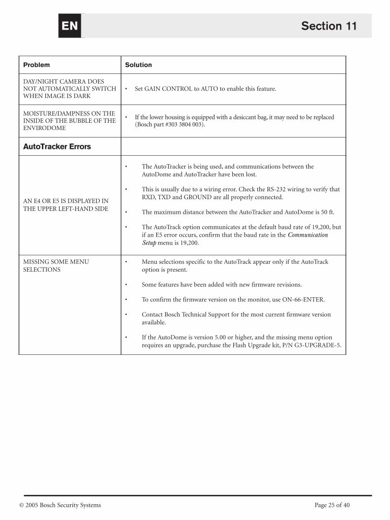
DAY/NIGHT CAMERA DOESNOT AUTOMATICALLY SWITCHWHEN IMAGE IS DARK
• Set GAIN CONTROL to AUTO to enable this feature.
MOISTURE/DAMPNESS ON THEINSIDE OF THE BUBBLE OF THEENVIRODOME
• If the lower housing is equipped with a desiccant bag, it may need to be replaced(Bosch part #303 3804 003).
AutoTracker Errors
AN E4 OR E5 IS DISPLAYED INTHE UPPER LEFT-HAND SIDE
• The AutoTracker is being used, and communications between theAutoDome and AutoTracker have been lost.
• This is usually due to a wiring error. Check the RS-232 wiring to verify thatRXD, TXD and GROUND are all properly connected.
• The maximum distance between the AutoTracker and AutoDome is 50 ft.
• The AutoTrack option communicates at the default baud rate of 19,200, butif an E5 error occurs, confirm that the baud rate in the CommunicationSetup menu is 19,200.
MISSING SOME MENUSELECTIONS
• Menu selections specific to the AutoTrack appear only if the AutoTrackoption is present.
• Some features have been added with new firmware revisions.
• To confirm the firmware version on the monitor, use ON-66-ENTER.
• Contact Bosch Technical Support for the most current firmware versionavailable.
• If the AutoDome is version 5.00 or higher, and the missing menu optionrequires an upgrade, purchase the Flash Upgrade kit, P/N G3-UPGRADE-5.

EN
© 2005 Bosch Security Systems Page 26 of 40
SECTION 12
AUTODOME LOCKED COMMANDS
Access to the AutoDome may be password-protected. See SECTION 4, AutoDome Security for details. To use Locked Commands, first unlockthe AutoDome via OFF-90-ENTER. All locked settings, except FastAddress, can then be changed via ON-46-ENTER. Disallow these commands via
ON-90-ENTER.
Section 12
Commands Keystrokes Description
FastAddress On-999-Enter Sets/changes the dome address using the keyboard and on-screen menus. (for cameras not already configured).
On-998-Enter Sets/changes the dome address using the keyboard and on-screen menus. (for all cameras, even those already configured).
Display FastAddress On-997-Enter Briefly displays all dome addresses.
Auto Iris On/Off-3-Enter Camera (Iris) adjusts automatically/manually (On/Off) to light conditions.
Auto Focus On/Off-4-Enter Camera automatically/manually (On/Off) focuses.
Gain Control On/Off-43-Enter Turns gain control to Automatic or Off. When in Automatic mode, the gain increases to compensate for darker scenes.
On-screen Display On/Off-60-Enter Turns On/Off the On-screen Display. When off, there is no On-screen feedback.
On-screen On/Off-61-Enter Changes the characters and position of the display.Display Adjust On-screen instructions are provided.
Newer versions of the Receiver/Driver, in combination with firmware version 5.10 or higher, allow the brightness to be adjusted. The firmware automatically detects whether the Receiver/Driver supports this, and displays the selection whenavailable.
Sector Title Edit On/Off-63-Enter Edits the current Sector name. On-screen instructions are provided.
Sector Blanking On-86-Enter Masks video from being displayed in selected sectors.
Privacy Masking On-87-Enter Masks video from being displayed in selected zones.
Bypass All Off-86-Enter Removes all viewing restrictions imposed by sector blanking/privacy masking but keeps their locations in memory.Masks/Blanking or Off-87-Enter On-86/87-Enter reactivates all masks/blanking.
Lock/Unlock On/Off-90-Enter Allows/Disallows Locked Commands to be accessed. Commands
Password Set-802-Enter Sets or displays password. See AutoDome Security, SECTION 4 for details.
Factory Home Set-110-Enter SET recalibrates camera and returns it to home position.Position
Restore Defaults On-40-Enter Restores Factory Defaults.
Left Limit Set-101-Enter Sets the current position as the left limit of Auto Pan. Default is 0 degrees.
Right Limit Set-102-Enter Sets the current position as the right limit of Auto Pan. Default is 359.9 degrees.
Inactivity On/Off-9-Enter Selects the mode that the dome reverts to after a duration without operator activity. Default is OFF.
Preset On/Off-15-Enter Increase/Decrease (On/Off) the time between Presets during Preset Tour.Tour Period
AutoPivot On/Off-18-Enter Allows a subject to be followed while beneath the camera, without inverting the picture. Default is ON.
AutoTrack Comms On/Off-77-Enter Enables/Disables the Tracker. When disabled, no status will be displayed. Since this is not retained in non-volatile memory, if the AutoDome receives Tracker messages on start-up, the Tracker will be enabled again (AutoTracker option ONLY).
Camera Height On/Off-79-Enter Selects the height of the camera in respect to the surface being monitored with the AutoTracker feature (AutoTracker option ONLY).
Select On/Off-35-Enter Adjusts camera color (white balance) for specific settings.White Balance or On/Off-30-Enter
Sharpness On/Off-44-Enter Picture (vertical aperture) sharpens/softens.
Iris Adjust On/Off-11-Enter Edits the Auto Iris level.
Shutter On/Off-23-Enter Sliding scale from 1 second to 1/10,000 sec,(Frame Integration) with Auto Slow Shutter at extreme left.
Sync Mode On/Off-42-Enter Sets camera sync for external-line/internal-crystal (On/Off).
Adjust Line On/Off-41-Enter Changes the phase delay of the camera when inLock Phase external line lock mode.
Switch Polarity On-91-Enter Switches the polarity of the Zoom, Focus, and Iris controls.
Digital Zoom On/Off-80-Enter Enables (On) or disables (Off) the digital zoom.
Night Threshold Adj. On-58-Enter Selects the video level at which the camera switches to night mode (Day/Night only).
QuickSet Select On-59-Enter Allows mode selection where multiple camera settings are set according to the chart below (Day/Night only).
SE
TU
P
GE
NE
RA
L
PT
ZC
AM
ER
A
QuickSet Mode Name Gain Control IRIS Slow Shutter IR Filter
Low Light Color Auto Auto Auto In
Full Auto w/ Slow Shutter Auto Auto Auto Auto
Full Auto w/o Slow Shutter Auto Auto 1/60 Auto
Night w/ Slow Shutter Auto Auto Auto Out
Night w/o Slow Shutter Auto Auto 1/60 Out

EN
© 2005 Bosch Security Systems Page 27 of 40
Section 13
SECTION 13
ADVANCED MENU
Main Menu
Depending on the AutoDome password security set for your system, a password may be required to access the ADVANCEDMENU. This enhanced software makes programming and customiz-ing the AutoDome easy. All settings are editable via the Main Menu.Press ON-46-ENTER to enter the Main Menu. If no menu is displayed, the system may be locked. To unlock the AutoDome, pressOFF-90-ENTER, and follow the on-screen commands to edit the set-tings. As indicated at the bottom of the screen, use IRIS to SAVE andEXIT or to RETURN to a previous menu.
CAMERA SETUP(See FIGURE 13A for CAMERA SETUP menu hierarchy).
White Balance – This camera function maintains proper color reproduction as the color temperature of the scene changes(i.e. daylight, flourescent). The Factory Default setting is AUTOMATIC.Choices:Extended Auto WB . . . .Camera adjusts color using extended range.
*Automatic WB . . . . . . . .Camera constantly adjusts the color.Indoor WB . . . . . . . . . . .Camera optimizes color for typical indoor conditions.Outdoor WB . . . . . . . . . .Camera optimizes color for typical outdoor conditions.One Push WB . . . . . . . .Sets the camera’s color settings for the current scene. Zoom on a well lit, white object
(i.e. a white wall or paper) before activating.
Gain Control – Electronically brightens darker scenes which may cause graininess in low light scenes. The Factory Defaultsetting is AUTO.
Choices:Off . . . . . . . . . . . . . . . . . . .Camera uses only the IRIS to adjust to low light.*Auto . . . . . . . . . . . . . . . . .Camera adds electronic gain based on lighting conditions.
Max Gain Level – Adjusts the maximum gain level that Gain control will adjust to when set to AUTO.
Choices: . . . . . . . . . . . . . .Sliding Scale from 1 to 6 (in 4 dB gain steps).
Sharpness – Adjusts the sharpness/detail of the picture. The Factory Default setting is six on the sliding scale of about 16.
Choices: . . . . . . . . . . . . . .Sliding Scale from –(soft) to +(sharp).
Synch Mode – Sets the synch mode of the camera. The Factory Default setting is LINE LOCK.
Choices:Crystal . . . . . . . . . . . . . . . . .Camera is synchronized to an internal crystal (recommended if there is noise on the power line).
*Line Lock . . . . . . . . . . . .Camera is synchronized to AC power. This eliminates picture roll in multicamera systems.
Line Lock Delay – Optimizes LINE LOCK mode to eliminate picture roll in multiphase power applications. The FactoryDefault setting is zero.
Choices: . . . . . . . . . . . . . .Sliding Scale (–0° to 359°).
Backlight Compensation – Improves the image quality when the background has a high level of illumination.
Choices: . . . . . . . . . . . . . .On, Off.
Shutter – Sliding scale from 1 sec to 1/10,000 sec, with Auto Slow Shutter at extreme left.
Restore Defaults – Restores ALL choices, for this submenu ONLY, back to the Factory Defaults.
Choices: . . . . . . . . . . . . . .Yes, No.
EN
© 2005 Bosch Security Systems Page 28 of 40
Section 13
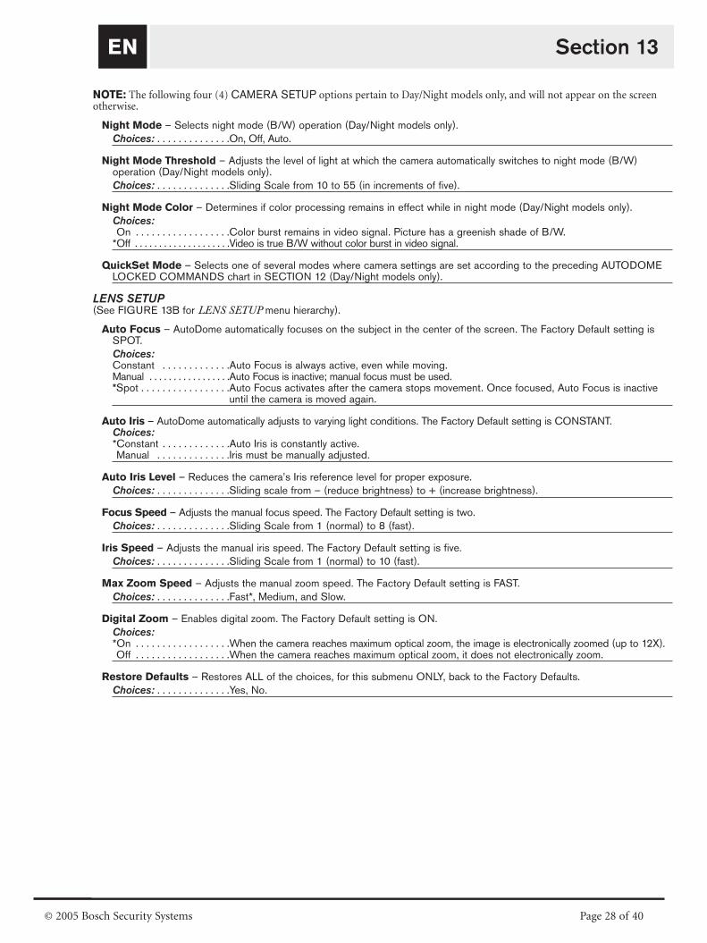
NOTE: The following four (4) CAMERA SETUP options pertain to Day/Night models only, and will not appear on the screen otherwise.
Night Mode – Selects night mode (B/W) operation (Day/Night models only).
Choices: . . . . . . . . . . . . . .On, Off, Auto.
Night Mode Threshold – Adjusts the level of light at which the camera automatically switches to night mode (B/W) operation (Day/Night models only).
Choices: . . . . . . . . . . . . . .Sliding Scale from 10 to 55 (in increments of five).
Night Mode Color – Determines if color processing remains in effect while in night mode (Day/Night models only).
Choices:On . . . . . . . . . . . . . . . . . .Color burst remains in video signal. Picture has a greenish shade of B/W.
*Off . . . . . . . . . . . . . . . . . . . .Video is true B/W without color burst in video signal.
QuickSet Mode – Selects one of several modes where camera settings are set according to the preceding AUTODOMELOCKED COMMANDS chart in SECTION 12 (Day/Night models only).
LENS SETUP(See FIGURE 13B for LENS SETUP menu hierarchy).
Auto Focus – AutoDome automatically focuses on the subject in the center of the screen. The Factory Default setting isSPOT.
Choices:Constant . . . . . . . . . . . . .Auto Focus is always active, even while moving.Manual . . . . . . . . . . . . . . . . .Auto Focus is inactive; manual focus must be used.*Spot . . . . . . . . . . . . . . . . .Auto Focus activates after the camera stops movement. Once focused, Auto Focus is inactive
until the camera is moved again.
Auto Iris – AutoDome automatically adjusts to varying light conditions. The Factory Default setting is CONSTANT.Choices:*Constant . . . . . . . . . . . . .Auto Iris is constantly active.Manual . . . . . . . . . . . . . .Iris must be manually adjusted.
Auto Iris Level – Reduces the camera’s Iris reference level for proper exposure.
Choices: . . . . . . . . . . . . . .Sliding scale from – (reduce brightness) to + (increase brightness).
Focus Speed – Adjusts the manual focus speed. The Factory Default setting is two.
Choices: . . . . . . . . . . . . . .Sliding Scale from 1 (normal) to 8 (fast).
Iris Speed – Adjusts the manual iris speed. The Factory Default setting is five.
Choices: . . . . . . . . . . . . . .Sliding Scale from 1 (normal) to 10 (fast).
Max Zoom Speed – Adjusts the manual zoom speed. The Factory Default setting is FAST.
Choices: . . . . . . . . . . . . . .Fast*, Medium, and Slow.
Digital Zoom – Enables digital zoom. The Factory Default setting is ON.
Choices:*On . . . . . . . . . . . . . . . . . .When the camera reaches maximum optical zoom, the image is electronically zoomed (up to 12X).Off . . . . . . . . . . . . . . . . . .When the camera reaches maximum optical zoom, it does not electronically zoom.
Restore Defaults – Restores ALL of the choices, for this submenu ONLY, back to the Factory Defaults.
Choices: . . . . . . . . . . . . . .Yes, No.

EN
© 2005 Bosch Security Systems Page 29 of 40
Section 13
PTZ SETUP
(See FIGURE 13C for the PTZ SETUP menu hierarchy).
Autopan Speed – Adjusts speed of the camera during Auto Pan/ Auto Scan. The Factory Default setting is 30°/sec.
Choices: . . . . . . . . . . . . . .Sliding Scale from 1°/sec to 60°/sec.
Tour Period – Changes dwell time between Presets during a Preset Tour. The Factory Default setting is five sec.
Choices: . . . . . . . . . . . . . .Sliding Scale from 3 sec to 10 min.
PTZ Fixed Speed – Sets Pan/Tilt speed when controlled by a fixed speed controller. The Factory Default setting is four.
Choices: . . . . . . . . . . . . . .Sliding Scale from 1 (slow) to 15 (fast).
Inactivity – Selects the mode that the dome reverts to after the period of time specified in the Inactivity Period (next menuoption), without operator activity. The Factory Default setting is OFF.
Choices:*Off . . . . . . . . . . . . . . . . . .Remains on current scene indefinitely.Scene 1 . . . . . . . . . . . . .Returns to Preset 1.Prev Aux . . . . . . . . . . . . .Returns to previous activity (previous activities include Aux commands 1, 2, 8, 50, 52).
Inactivity Period – The time period of inactivity before the above action occurs. Default setting is two min.
Choices: . . . . . . . . . . . . . .Sliding Scale from 3 sec to 10 min.
AutoPivot – AutoPivot automatically rotates the camera 180° when following a subject travelling directly beneath the camera.The Factory Default setting is ON.
Choices:*On . . . . . . . . . . . . . . . . . .Camera automatically pivots.Off . . . . . . . . . . . . . . . . . .Camera stops tilting when looking straight down.
Restore Defaults – Use this to restore ALL choices for this submenu ONLY, back to the Factory Defaults.
Choices: . . . . . . . . . . . . . .Yes, No.
NOTE: The following two (2) PTZ SETUP options refer to AutoTrack models only, and will not appear on the screen otherwise.
AutoTrack Comms: – Enables/Disables the AutoTracker completely, including all communications.Choices: . . . . . . . . . . . . .On (enable), Off (disable).
Camera Height: – Selects the height of the camera in relation to the surface being viewed.Choices: . . . . . . . . . . . . .From 2.4 m to 30.7 m (8 ft to 100 ft); use the Joystick Up/Down to adjust.
DISPLAY SETUP
(See FIGURE 13D for DISPLAY SETUP menu hierarchy.)
Title OSD – Controls whether sector or shot title are displayed. The Factory Default setting is MOMENTARY.Choices:*Momentary . . . . . . . . . . .Titles are displayed for a few sec, then disappear from the screen.On . . . . . . . . . . . . . . . . . . .Titles are displayed.Off . . . . . . . . . . . . . . . . . . .Titles are hidden.
Camera OSD – Controls whether the camera information is displayed (such as digital zoom, Iris OPEN/close, etc.). The Factory Default is ON.Choices:*On . . . . . . . . . . . . . . . . .Camera commands are displayed.Off . . . . . . . . . . . . . . . . . . .Camera commands are hidden.
Display Adjust – Adjusts the vertical position of the on-screen display. See the on-screen display for instructions.
Sector Blanking – Selects sectors for video blanking. Sectors available are 1 to 16. See the on-screen display for instructions.
Privacy Masking – Up to six (6) privacy masks are available to mask out sensitive areas.
Restore Defaults – Restores ALL choices for this submenu ONLY, back to the Factory Defaults.
Choices: . . . . . . . . . . . . . .Yes, No.

EN
© 2005 Bosch Security Systems Page 30 of 40
Section 13
COMMUNICATION SETUP
(See FIGURE 13E for COMMUNICATION SETUP hierarchy).
Baud Rate – Controls baud rate for AutoDome communication in the Normal mode. Factory Default is 9600.
Choices: . . . . . . . . . . . . .9600*, 19200, 38400, 57600.
Bilinx - Enables/Disables the Bilinx communications directly through the coax. Factory Default is ON.Choices: ..............On*, Off.
Restore Defaults – Restores ALL choices for this submenu ONLY, back to the Factory Defaults.
Choices: . . . . . . . . . . . . . .Yes, No.
ALARM SETUP
(See FIGURE 13F for ALARM SETUP hierarchy).
Input 1 thru 4 – Contains a submenu of choices for Input type, and the action to occur when the alarm is activated.
Alarm 1 through 4
Input – Controls the input type that the camera will be expecting. Factory Default is OFF.
Choices: . . . . . . . .OFF*, Normally Open (N.O.), Normally Closed (N.C.).
Action – There are three standard choices to determine how the AutoDome will respond when an alarm input is activated, and one additional choice that will appear ONLY when the AutoTracker is being used.
Go to Shot – The AutoDome moves to the pre-position (shot) selected. Default is the input number.
Choices: . . . . .0 to 99.NOTE: If 0 is selected and OSD is set to YES, the camera will not move, but will display a flashing ALARMprompt.
OSD – Controls whether a visual ALARM prompt will be displayed. Default is YES.
Choices: . . . . .Yes*, No.
Transmit – Controls whether an alarm message will be transmitted via RS-232/RS-485. Default is NO.
Choices: . . . . .Yes, No*.
Track – Controls whether AutoTrack should be activated when an alarm occurs. Displayed on AutoTrack modelsONLY.
Choices: . . . .Yes, No.
AutoTrack / Relay Output – Contains a submenu of choices that control how the relay output will function.
Period – Controls the time period that the relay output will remain activated. Default is FOLLOW INPUT.
Choices: FOLLOW INPUT* – The relay output will remain activated as long as the alarm input is active.
LATCHED – The relay output will latch ON and remain activated until an OFF-65 command is sent twice. Thefirst OFF-65 command clears the alarm OSD from the display; the second OFF-65 commanddeactivates the output.
SLIDING SCALE – from 1 sec to 10 min. The relay output remains activated for the selected time period.Trigger By: Select which alarm input will cause the relay output to Activate. Trigger By applies to Relay Output only,not AutoTrack.
Choices: ..........Input 1 through 4: Yes, No.Alarm Status – Displays the states of the Alarm inputs and the relay output. This is an active display, that changesas the Alarm Status changes. It is informational only.
Restore Defaults – Restores ALL choices for this submenu ONLY, back to the Factory Defaults.
Choices: . . . . . . . . . . . . . .Yes, No.
LANGUAGE SETUP
(See FIGURE 13G for LANGUAGE SETUP hierarchy.)
Language – Selects the language to be displayed.
Choices: English, Spanish, French, German, Polish and Portuguese.

EN
© 2005 Bosch Security Systems Page 31 of 40
Section 13
Figure 13A Camera Setup
Figure 13B Lens Setup
CAMERA
SETUP
WHITE
BALANCE
Extended Auto WB
*Automatic WB
Indoor WB
Outdoor WB
One Push WB
GAIN
CONTROL
SHARPNESS
SYNCH
MODE
LINE LOCK
DELAY
QUICKSET
MODE
BACKLIGHT
COMPENSATION
MAX GAIN
LEVEL
Off
*Auto
Sliding Scale1 6*default = 4
Sliding Scale– (soft)*default = 6 (on scale of ~16)
+ (sharp)
Crystal
*Line Lock
Sliding Scale359°
*default = 0 –0°
Sliding Scale1/10,000 sec
Auto Slow Shutter
1 sec
NIGHT MODE
NIGHT MODE
THRESHOLD
NIGHT MODE
COLOR
OnOff
*Auto
SlidingScale
10 55
On*Off
On*Off
* Factory Default
SHUTTER
**Da
y/N
igh
t Se
tting
s
** For Day/Night Models Only
RESTORE DEFAULTS
Yes
No
LENS
SETUP
AUTO
FOCUS
AUTO
IRIS
IRIS
SPEED
MAX ZOOM
SPEED
DIGITAL
ZOOM
FOCUS
SPEED
*Constant
Manual
Sliding Scale1 (normal) 8 (fast)*default = 2
*On
Off
* Factory Default
Constant
Manual
*SpotSliding Scale1 (normal) 10 (fast)
*default = 5
*Fast
Medium
Slow
AUTO IRIS
LEVEL
Sliding Scale– (reduce brightness) + (increase brightness)
RESTORE DEFAULTS
Yes
No
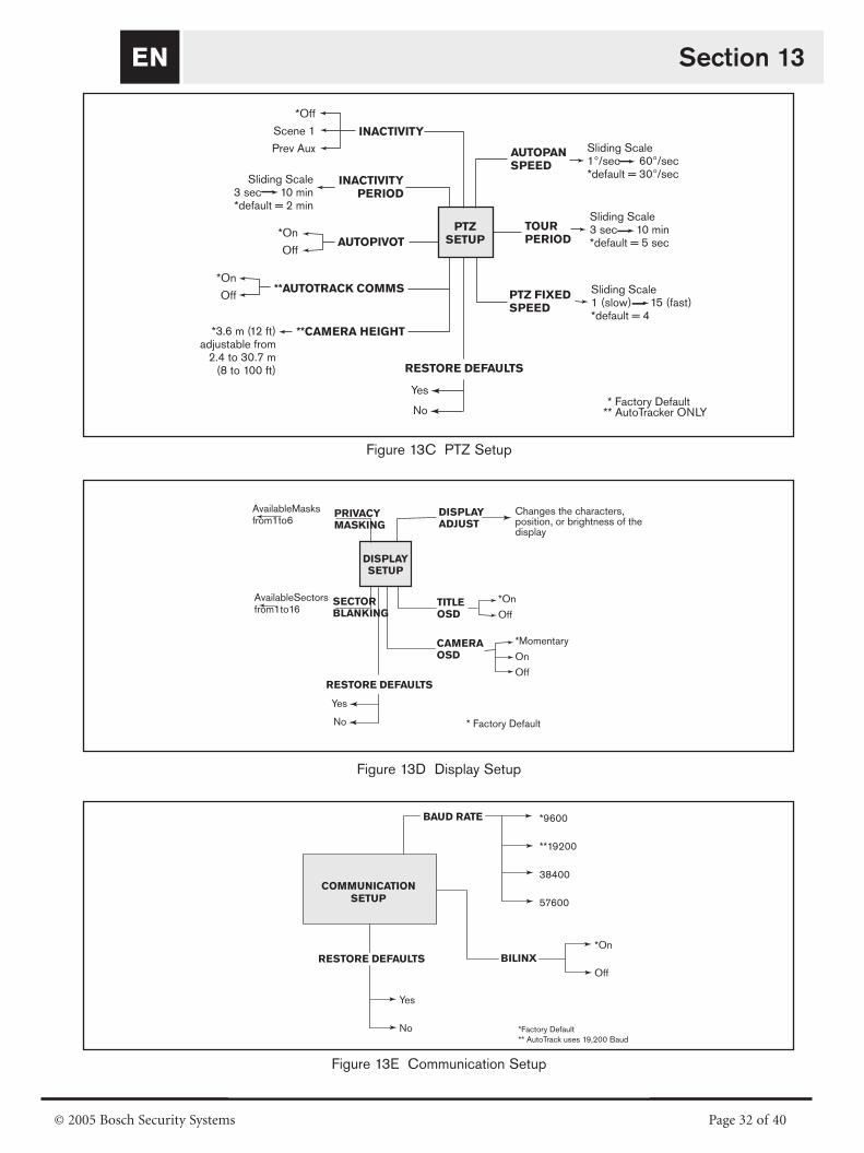
EN
© 2005 Bosch Security Systems Page 32 of 40
Section 13
Figure 13C PTZ Setup
Figure 13D Display Setup
Figure 13E Communication Setup
PTZ
SETUP
AUTOPAN
SPEED
TOUR
PERIOD
INACTIVITY
PERIOD
AUTOPIVOT
**AUTOTRACK COMMS
**CAMERA HEIGHT
INACTIVITY
Sliding Scale3 sec 10 min*default = 5 sec
*On
Off
*On
Off
* Factory Default** AutoTracker ONLY
Sliding Scale3 sec 10 min*default = 2 min
PTZ FIXED
SPEED
Sliding Scale1°/sec 60°/sec *default = 30°/sec
Sliding Scale1 (slow) 15 (fast) *default = 4
*3.6 m (12 ft)adjustable from
2.4 to 30.7 m(8 to 100 ft)
*Off
Scene 1
Prev Aux
RESTORE DEFAULTS
Yes
No
COMMUNICATION
SETUP
BAUD RATE
BILINX
*9600
**19200
38400
57600
*Factory Default
** AutoTrack uses 19,200 Baud
RESTORE DEFAULTS
Yes
No
*On
Off
DISPLAY
SETUP
DISPLAY
ADJUST
TITLE
OSD
SECTOR
BLANKING
*On
Off
Changes the characters,position, or brightness of thedisplay
* Factory Default
Available Sectorsfrom 1 to 16
CAMERA
OSD
*Momentary
On
Off
PRIVACY
MASKING
Available Masksfrom 1 to 6
RESTORE DEFAULTS
Yes
No

EN
© 2005 Bosch Security Systems Page 33 of 40
Section 13
Figure 13F Alarm Setup
Figure 13G Language Setup
*Factory Default
**AutoTracker ONLY***A pressurized dome uses Alarm Input 4 for the pressure limit switch
ALARM
SETUP
INPUT 1
INPUT 2
INPUT 3
***INPUT 4
Input
Action
*Off
N.O. (Normally Open)
N.C. (Normally Closed)
Go to Shot
OSD
Transmit:
**Track
0 to 99;
*Default = Input Number
*Yes, No
*No, Yes
*No, Yes
RESTORE DEFAULTS
Yes
No
RELAY
OUTPUTPeriod *Follow Input
Latched
Sliding Scale
1 sec to 10 min
Triggered
by:
Input 1
Input 2
Input 3
Input4
*No, Yes
Alarm Status
Displays the status of the
four Alarm Inputs and the
Relay Output
AutoTrack Output Period * Follow Input
Latched
Sliding Scale 1 sec to 10 min
LANGUAGE
SETUP
*English
Spanish
French
German
Portuguese
Polish
*Factory Default
RESTORE DEFAULTS
Yes
No

EN
© 2005 Bosch Security Systems Page 34 of 40
APPENDIX A
Power Wiring Guide
AutoDome Power Wiring Connections
Refer to the following diagram to ensure proper wiring of theAutoDome. If using the ENV-PSU for power, use the THREE WIRE POWER distances identified below.
WARNING: Failure to correctly wire the power to theEnviroDome could result in heater malfunction.
NOTE: If using the ENV-PSU with the AutoTracker option, theRS-232 connections (RXD, TXD, GND) must be used.
The maximum distance for RS-232 communications is 50 ft.
Appendix A
TWO WIRE POWER
C– 24 VAC
THREE WIRE POWER (EnviroDome) FOUR WIRE POWER (EnviroDome)
Transformer Output24 VAC @50 VA
Add WireJumper
Dome Connector Dome Connector Dome Connector
Transformer Output24 VAC @30 VA
Transformer Output24 VAC @20 VA
Transformer Output24 VAC @30 VA
Transformer Output24 VAC @20 VA
AWGMax. Distance - ft (m)18 90 ft (27.43)16 140 ft (42.67)14 225 ft (68.58)
C+ GND RXD TXD GND H* C–C+ GND RXD TXD GND H* 24 VAC 24 VACC–C+ GND RXD TXD GND H*
Neu
tral
HotHot
Hot
HotHot
Neu
tral
Neu
tral
Neu
tral
FOR EnviroDome
AWGMax. Distance - ft (m)18 225 ft (68.58)16 358 ft (109.12)14 570 ft (173.74)
FOR INDOOR UNITS ONLY (UNITS NOT REQUIRING HEATERS):
AWGMax. Distance - ft (m)18 112 ft (34.14)16 180 ft (57.91)14 285 ft (86.87)
AWGMax. Distance - ft (m)18 150 ft (45.72)16 239 ft (72.85)14 380 ft (115.82)
24 VAC @ 20 VA
FOR EnviroDome FOR EnviroDome
*Heater connection for EnviroDome only.

EN
© 2005 Bosch Security Systems Page 35 of 40
APPENDIX B
Gasket Installation (to meet IP66/NEMA 4X, Dust-tight and Powerful Jetting)
Appendix B
Install Gasket with Lip on Top.
Plate Holds Gasket Securely
Insert 4 Screws

EN
© 2005 Bosch Security Systems Page 36 of 40
AutoDome®
and EnviroDome®
Indoor Pendant
In-ceiling Model
User ManualVersion 5.3
Security you can rely on
EN
NOTE: Remove this User Manual and supply to user.

EN
© 2005 Bosch Security Systems Page 37 of 40
ON-SCREEN PROGRAMMINGThe AutoDome software offers user-friendly, on-screen pro-gramming. A few common commands are shown below.Additional commands are listed at the end of this manual.
Saving a scene (Preset)
The AutoDome allows up to 99 scenes to be saved and recalledinstantly. A saved scene is called a Preset. When a Preset is saved,the position, zoom, and most camera settings are stored.
Figure 1 Preset menu
SET-100-ENTER displays the Preset menu (see FIGURE 1). Menuoptions are store, delete, name, or edit. Up to 99 scenes can besaved, and the system automatically selects the next availablenumber. When a Preset is saved, it can be named via the joystick,FOCUS, and IRIS (see FIGURE 2). The name can be up to 16 characters long. This Preset can later be viewed using theSHOT-#-ENTER command, where # is 1-99.
Figure 2 Naming a scene (Preset)
Preset Tour
Once Presets are stored, the AutoDome can cycle through all Presetsor selected Presets. This is called a Preset tour. To include or removepresets on a tour, type SET-900-ENTER. This displays the currentPresets, and indicates if they are on the tour. Follow the on-screeninstructions to include/remove Presets from the tour.Note: Presets removed from the tour can still be accessed manually).
Type ON-8-ENTER to activate the preset tour. To change the timeduration between presets, type ON-15-ENTER and follow the on-screen instructions.
Figure 3 Preset tour menu
Setting the Preset Tour period
To change the time duration between presets in a Preset Tour, typeON-15-ENTER, and use the joystick for adjustments (see FIGURE 4).
Figure 4 Preset tour period adjustments
User Manual

EN User Manual
Record/Playback Tours
Two independent macros (series of commands) can be recorded;A & B. These macros can be several hours in duration, althoughtours involving constant commands only last minutes. Whilerecording, the on-screen display indicates remaining memory (seeFIGURE 5). To begin recording on A, move the camera to thedesired starting point and type ON-100-ENTER. The AutoDomenow records all camera activities, until the recording is ended byOFF-100-ENTER. Once A has been recorded, B is available via theON/OFF-101-ENTER command. Playback can be continuous(ON-50-ENTER for A; ON-52-ENTER for B) or one shot(ON-51-ENTER for A; ON-53-ENTER for B).
Figure 5 Recording
Changing AutoPan and AutoScan speeds
The AutoPan and AutoScan speeds (see FIGURE 6) can beadjusted via ON-14-ENTER. Use the joystick to adjust the speed.It is helpful for the Pan or Scan to be active when enteringADJUST mode, to see the speed change.
Figure 6 AutoPan / AutoScan speed adjust
© 2005 Bosch Security Systems Page 38 of 40
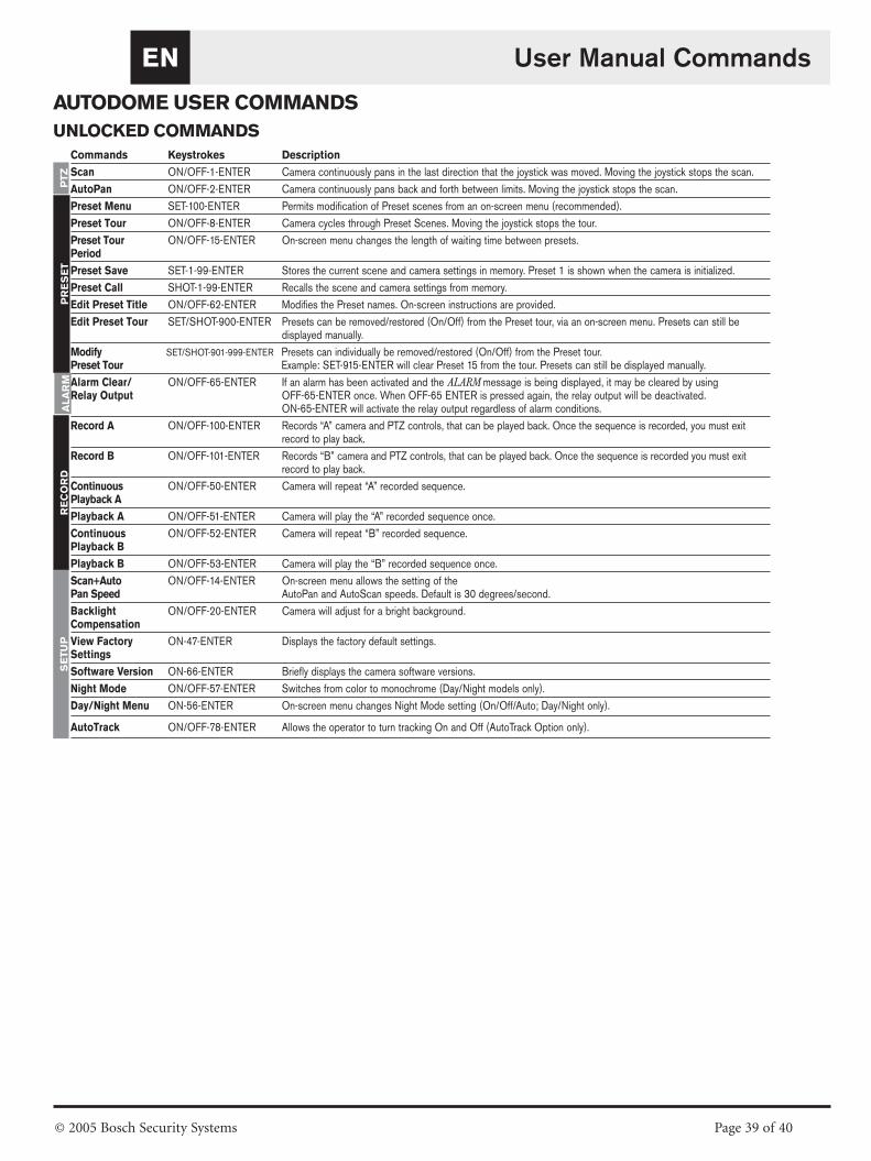
EN
AUTODOME USER COMMANDS
UNLOCKED COMMANDS
User Manual Commands
Commands Keystrokes Description
Scan ON/OFF-1-ENTER Camera continuously pans in the last direction that the joystick was moved. Moving the joystick stops the scan.
AutoPan ON/OFF-2-ENTER Camera continuously pans back and forth between limits. Moving the joystick stops the scan.
Preset Menu SET-100-ENTER Permits modification of Preset scenes from an on-screen menu (recommended).
Preset Tour ON/OFF-8-ENTER Camera cycles through Preset Scenes. Moving the joystick stops the tour.
Preset Tour ON/OFF-15-ENTER On-screen menu changes the length of waiting time between presets.Period
Preset Save SET-1-99-ENTER Stores the current scene and camera settings in memory. Preset 1 is shown when the camera is initialized.
Preset Call SHOT-1-99-ENTER Recalls the scene and camera settings from memory.
Edit Preset Title ON/OFF-62-ENTER Modifies the Preset names. On-screen instructions are provided.
Edit Preset Tour SET/SHOT-900-ENTER Presets can be removed/restored (On/Off) from the Preset tour, via an on-screen menu. Presets can still be displayed manually.
Modify SET/SHOT-901-999-ENTER Presets can individually be removed/restored (On/Off) from the Preset tour. Preset Tour Example: SET-915-ENTER will clear Preset 15 from the tour. Presets can still be displayed manually.
Alarm Clear/ ON/OFF-65-ENTER If an alarm has been activated and the ALARM message is being displayed, it may be cleared by using Relay Output OFF-65-ENTER once. When OFF-65 ENTER is pressed again, the relay output will be deactivated.
ON-65-ENTER will activate the relay output regardless of alarm conditions.
Record A ON/OFF-100-ENTER Records “A” camera and PTZ controls, that can be played back. Once the sequence is recorded, you must exitrecord to play back.
Record B ON/OFF-101-ENTER Records “B” camera and PTZ controls, that can be played back. Once the sequence is recorded you must exitrecord to play back.
Continuous ON/OFF-50-ENTER Camera will repeat “A” recorded sequence.Playback A
Playback A ON/OFF-51-ENTER Camera will play the “A” recorded sequence once.
Continuous ON/OFF-52-ENTER Camera will repeat “B” recorded sequence.Playback B
Playback B ON/OFF-53-ENTER Camera will play the “B” recorded sequence once.
Scan+Auto ON/OFF-14-ENTER On-screen menu allows the setting of the Pan Speed AutoPan and AutoScan speeds. Default is 30 degrees/second.
Backlight ON/OFF-20-ENTER Camera will adjust for a bright background. Compensation
View Factory ON-47-ENTER Displays the factory default settings.Settings
Software Version ON-66-ENTER Briefly displays the camera software versions.
Night Mode ON/OFF-57-ENTER Switches from color to monochrome (Day/Night models only).
Day/Night Menu ON-56-ENTER On-screen menu changes Night Mode setting (On/Off/Auto; Day/Night only).
AutoTrack ON/OFF-78-ENTER Allows the operator to turn tracking On and Off (AutoTrack Option only).
PT
ZP
RE
SE
TA
LA
RM
RE
CO
RD
SE
TU
P
© 2005 Bosch Security Systems Page 39 of 40

© 2005 Bosch Security Systems GmbH
3935 890 43816 05-07 | Updated February 15, 2005 | Data subject to change without notice.
Americas
Bosch Security Systems
130 Perinton Parkway
Fairport, New York, 14450, USA
Phone: +1 (585) 223 4060
Fax: +1 (585) 223 9180
E-mail: [email protected]
www.boschsecurity.us
Europe, Middle East, Africa
Bosch Security Systems B.V.
P.O. Box 80002
5600 JB Eindhoven, The Netherlands
E-mail: [email protected]
http://www.boschsecurity.com
Asia-Pacific
Bosch Security Systems Pte Ltd
38C Jalan Pemimpin
Singapore 577180, Singapore
Phone: +65 319 3488
Fax: +65 319 3499
E-mail: [email protected]
http://www.boschsecurity.com