Embed Size (px)
Citation preview

AUTODOME IP 7000 HDVG5-7130, VG5-7230
en Operation Manual


Table of contents
1 Safety EN 61.1 About this Manual 61.2 Legal Information 61.3 Safety Precautions 61.4 Important Safety Instructions 61.5 Important Notices 81.6 Connection in Applications 121.7 Customer Support and Service 12
2 Unpacking 132.1 Parts List, Installation 132.2 Tools Required 152.3 Additional Products Required 17
3 System overview 184 Pre-installation Checklist 194.1 Stabilization 20
5 Installing the Optional SD Card 216 Mount Power Supply Box (Wall, Mast (Pole), and Corner Mounts) 227 Installing the Pendant Arm Wall, Corner, and Mast (Pole) Mounts 247.1 Description 247.2 Route Wires and Attach Connectors 247.3 Route Power through Intermediate Power Supply Box 287.4 Attach Pendant Arm to Power Supply Box 317.5 Make Connections in the Power Supply Box 327.6 Installing the VGA-PEND-WPLATE 337.7 Attach Pendant to Arm and Tighten 37
8 Installing the Roof Parapet and Pipe Mounts 408.1 Description 408.2 Route Wires and Attach Connectors 408.3 Attach Cover Door to Power Supply Box 468.4 Installing the VGA-ROOF-MOUNT 478.5 Installing the VG4-A-9543 Pipe Mount 508.6 Wire the Pipe Interface Board 528.7 Attach Pendant to Pipe and Tighten 568.8 Make Connections in the Power Supply Box 58
9 Installing the In-Ceiling Mount 599.1 Description 599.2 Dimensions 599.3 Prepare Drywall Ceiling for Installation 599.4 Prepare Suspension Ceiling for Installation 599.5 Wire the Interface Box 619.6 Interface Box Connections 629.7 Installing the Ceiling (IP54 Housing) Gasket 649.8 Attach Housing to the Interface Box 659.9 Secure Housing to Ceiling 67
10 Preparing the Bubble 6911 Connection 7211.1 Connecting the AUTODOME camera to the PC 72
AUTODOME IP 7000 HD Table of Contents | en 3
Bosch Security Systems Operation Manual 2014.10 | 2.1 | F.01U.283.679

11.2 Power Cable and Wire Distances Guides 7211.3 Ethernet Connections 7311.4 Fiber Optic Ethernet Media Converter (Optional) 7411.5 Alarms and Relay Connections 7511.6 Audio Connections (Optional) 78
12 Configuration 8112.1 System Requirements 8112.2 Configuring the Camera 8212.3 Configuring Audio (Optional) 85
13 Configuration via IP, Basic Mode 8613.1 Basic Mode: Device Access 8613.2 Basic Mode: Date/Time 8613.3 Basic Mode: Network 8613.4 Basic Mode: Encoder 8713.5 Basic Mode: Audio 8713.6 Basic Mode: Recording 8713.7 Basic Mode: System Overview 88
14 Configuration via IP, Advanced Mode 8914.1 Advanced Mode: General 8914.2 Identification 8914.3 Password 8914.4 Date/Time 9014.5 Display Stamping 9114.6 Advanced Mode: Web Interface 9314.7 Appearance 9314.8 LIVE Functions 9414.9 Logging 9514.10 Advanced Mode: Camera 9514.11 Installer Menu 9514.12 Encoder Profile 9714.13 Encoder Streams 10014.14 Privacy Masks 10214.15 Picture Settings 10314.16 Lens Settings 10614.17 PTZ Settings 10614.18 Scenes and Tours 10814.19 Sectors 10914.20 Miscellaneous 10914.21 Logs 10914.22 Audio 10914.23 Pixel Counter 11014.24 Advanced Mode: Recording 11014.25 Storage Management 11014.26 Recording Profiles 11214.27 Maximum Retention Time 11314.28 Recording Scheduler 11314.29 Recording Status 11414.30 Advanced Mode: Alarm 11514.31 Alarm Connections 115
4 en | Table of Contents AUTODOME IP 7000 HD
2014.10 | 2.1 | F.01U.283.679 Operation Manual Bosch Security Systems

14.32 VCA 11714.33 Virtual Masks 12114.34 Audio Alarm 12114.35 Alarm E-Mail 12214.36 Alarm Task Editor 12314.37 Alarm Rules 12314.38 Advanced Mode: Interfaces 12414.39 Alarm Inputs 12414.40 Alarm Outputs 12414.41 Advanced Mode: Network 12414.42 Network Access 12414.43 DynDNS 12714.44 Advanced 12714.45 Network Management 12814.46 Multicast 12914.47 Image Posting 13014.48 Accounts 13114.49 IPv4 Filter 13114.50 Encryption 13114.51 Advanced Mode: Service 13114.52 Maintenance 13114.53 Licenses 13314.54 Diagnostics 13314.55 System Overview 133
15 Operation 13415.1 Using the AUTODOME Camera 13415.2 Using Intelligent Tracking 14215.3 Recommended Use of Your Camera 145
16 Troubleshooting 14617 Maintenance 14818 Technical data 15019 User Command Table 151
AUTODOME IP 7000 HD Table of Contents | en 5
Bosch Security Systems Operation Manual 2014.10 | 2.1 | F.01U.283.679

Safety EN
About this ManualThis manual has been compiled with great care and the information it contains has beenthoroughly verified. The text was complete and correct at the time of printing. Because of theongoing development of products, the content of the manual may change without notice.Bosch Security Systems accepts no liability for damage resulting directly or indirectly fromfaults, incompleteness, or discrepancies between the manual and the product described.
Legal InformationCopyrightThis manual is the intellectual property of Bosch Security Systems, Inc. and is protected bycopyright. All rights reserved.TrademarksAll hardware and software product names used in this document are likely to be registeredtrademarks and must be treated accordingly.
Safety Precautions
Danger!
Indicates a hazardous situation which, if not avoided, will result in death or serious injury.
!Warning!
Indicates a hazardous situation which, if not avoided, could result in death or serious injury.
!
Caution!
Indicates a hazardous situation which, if not avoided, could result in minor or moderate
injury.
Notice!
Indicates a situation which, if not avoided, could result in damage to the equipment or
environment, or data loss.
Important Safety InstructionsRead, follow, and retain for future reference all of the following safety instructions. Heed allwarnings on the unit and in the operating instructions before operating the unit.1. Cleaning - Unplug the unit from the outlet before cleaning. Follow any instructions
provided with the unit. Generally, using a dry cloth for cleaning is sufficient, but a moistfluff-free cloth or leather shammy may also be used. Do not use liquid cleaners or aerosolcleaners.
2. Heat Sources - Do not install the unit near any heat sources such as radiators, heaters,stoves, or other equipment (including amplifiers) that produce heat.
1
1.1
1.2
1.3
1.4
6 en | Safety EN AUTODOME IP 7000 HD
2014.10 | 2.1 | F.01U.283.679 Operation Manual Bosch Security Systems

3. Ventilation - Any openings in the unit enclosure are provided for ventilation to preventoverheating and ensure reliable operation. Do not block or cover these openings. Do notplace the unit in an enclosure unless proper ventilation is provided, or the manufacturer'sinstructions have been adhered to.
4. Object and liquid entry - Never push objects of any kind into this unit through openingsas they may touch dangerous voltage points or short-out parts that could result in a fireor electrical shock. Never spill liquid of any kind on the unit. Do not place objects filledwith liquids, such as vases or cups, on the unit.
5. Lightning - For added protection during a lightning storm, or when leaving this unitunattended and unused for long periods, unplug the unit from the wall outlet anddisconnect the cable system. This will prevent damage to the unit from lightning andpower line surges.
6. Controls adjustment - Adjust only those controls specified in the operating instructions.Improper adjustment of other controls may cause damage to the unit. Use of controls oradjustments, or performance of procedures other than those specified, may result inhazardous radiation exposure.
7. Overloading - Do not overload outlets and extension cords. This can cause fire orelectrical shock.
8. Power cord and plug protection - Protect the plug and power cord from foot traffic,being pinched by items placed upon or against them at electrical outlets, and its exit fromthe unit. For units intended to operate with 230 VAC, 50 Hz, the input and output powercord must comply with the latest versions of IEC Publication 227 or IEC Publication 245.
9. Power disconnect - Units have power supplied to the unit whenever the power cord isinserted into the power source, or when High Power-over-Ethernet (High PoE) power isprovided over the Ethernet CAT 5E/6 cable. The unit is operational only when the ON/OFFswitch is in the ON position. The power cord is the main power disconnect device forswitching off the voltage for all units. When High PoE or PoE+ (820.3at) is used to powerthe unit, the power is provided over the Ethernet cable, which is then the main powerdisconnect device for switching off the voltage for all units.
10. Power sources - Operate the unit only from the type of power source indicated on thelabel. Before proceeding, be sure to disconnect the power from the cable to be installedinto the unit.For battery powered units, refer to the operating instructions.For external power supplied units, use only the recommended or approved powersupplies.For limited power source units, this power source must comply with EN60950.Substitutions may damage the unit or cause fire or shock.For 24 VAC units, voltage applied to the unit's power input should not exceed ±10%, or28 VAC. User-supplied wiring must comply with local electrical codes (Class 2 powerlevels). Do not ground the supply at the terminals or at the unit's power supply terminals.If unsure of the type of power supply to use, contact your dealer or local power company.
11. Servicing - Do not attempt to service this unit yourself. Opening or removing covers mayexpose you to dangerous voltage or other hazards. Refer all servicing to qualified servicepersonnel.
12. Damage requiring service - Unplug the unit from the main AC power source and referservicing to qualified service personnel when any damage to the equipment has occurred,such as:the power supply cord or plug is damaged;exposure to moisture, water, and/or inclement weather (rain, snow, etc.);liquid has been spilled in or on the equipment;
AUTODOME IP 7000 HD Safety EN | en 7
Bosch Security Systems Operation Manual 2014.10 | 2.1 | F.01U.283.679

an object has fallen into the unit;unit has been dropped or the unit cabinet is damaged;unit exhibits a distinct change in performance;unit does not operate normally when the user correctly follows the operating instructions.
13. Replacement parts - Be sure the service technician uses replacement parts specified bythe manufacturer, or that have the same characteristics as the original parts.Unauthorized substitutions may cause fire, electrical shock, or other hazards.
14. Safety check - Safety checks should be performed upon completion of service or repairsto the unit to ensure proper operating condition.
15. Installation - Install in accordance with the manufacturer's instructions and in accordancewith applicable local codes.
16. Attachments, changes or modifications - Only use attachments/accessories specified bythe manufacturer. Any change or modification of the equipment, not expressly approvedby Bosch, could void the warranty or, in the case of an authorization agreement, authorityto operate the equipment.
Important Notices
Accessories - Do not place this unit on an unstable stand, tripod, bracket, ormount. The unit may fall, causing serious injury and/or serious damage tothe unit. Use only with mounting solutions specified by the manufacturer.When a cart is used, use caution and care when moving the cart/unitcombination to avoid injury from tip-over. Quick stops, excessive force, oruneven surfaces may cause the cart/unit combination to overturn. Mount theunit per the installation instructions.
All-pole power switch - Incorporate an all-pole power switch, with a contact separation of atleast 3 mm, into the electrical installation of the building. If it is needed to open the housing,use this all-pole switch as the main disconnect device for switching off the voltage to the unit.Camera signal - Protect the cable with a primary protector if the camera signal is beyond 140feet, in accordance with NEC800 (CEC Section 60).Camera grounding: For mounting the camera in potentially dam environments, ensure toground the camera using the available ground connections.Camera lens - An assembled camera lens in the outdoor housing must comply and be tested inaccordance with UL/IEC60950. Any output or signal lines from the camera must be SELV orLimited Power Source. For safety reasons the environmental specification of the camera lensassembly must be within the environmental specification of -10 °C (14 °F) to 50 °C (122 °F).Camera signal - Protect the cable with a primary protector if the camera signal is beyond 140feet, in accordance with NEC800 (CEC Section 60).Coax grounding:– Ground the cable system if connecting an outside cable system to the unit.– Connect outdoor equipment to the unit's inputs only after this unit has had its grounding
plug connected to a grounded outlet or its ground terminal is properly connected to aground source.
– Disconnect the unit's input connectors from outdoor equipment before disconnecting thegrounding plug or grounding terminal.
– Follow proper safety precautions such as grounding for any outdoor device connected tothis unit.
1.5
8 en | Safety EN AUTODOME IP 7000 HD
2014.10 | 2.1 | F.01U.283.679 Operation Manual Bosch Security Systems

Section 810 of the National Electrical Code, ANSI/NFPA No.70, provides information regardingproper grounding of the mount and supporting structure, grounding of the coax to a dischargeunit, size of grounding conductors, location of discharge unit, connection to groundingelectrodes, and requirements for the grounding electrode.
Notice!
This device is intended for use in public areas only.
U.S. federal law strictly prohibits surreptitious recording of oral communications.
DisposalYour Bosch product has been developed and manufactured using high-quality materials and components that can be reused.This symbol means that electronic and electrical devices that have reachedthe end of their working life must be disposed of separately fromhousehold waste.In the EU, separate collecting systems are already in place for usedelectrical and electronic products. Please dispose of these devices at yourlocal communal waste collection point or at a recycling center.
Environmental statement - Bosch has a strong commitment towards the environment. Thisunit has been designed to respect the environment as much as possible.Electrostatic-sensitive device - Use proper CMOS/MOS-FET handling precautions to avoidelectrostatic discharge. NOTE: Wear required grounded wrist straps and observe proper ESDsafety precautions when handling the electrostatic-sensitive printed circuit boards.Fuse rating - For security protection of the device, the branch circuit protection must besecured with a maximum fuse rating of 16A. This must be in accordance with NEC800 (CECSection 60).Grounding and polarization - This unit may be equipped with a polarized alternating currentline plug (a plug with one blade wider than the other blade). This safety feature allows theplug to fit into the power outlet in only one way. If unable to insert the plug fully into theoutlet, contact a locally certified electrician to replace the obsolete outlet. Do not defeat thesafety purpose of the polarized plug.Alternately, this unit may be equipped with a 3-pole grounding plug (a plug with a third pin forearth grounding). This safety feature allows the plug to fit into a grounded power outlet only.If unable to insert the plug into the outlet, contact a locally certified electrician to replace theobsolete outlet. Do not defeat the safety purpose of the grounding plug.Moving - Disconnect the power before moving the unit. Move the unit with care. Excessiveforce or shock may damage the unit.Outdoor signals - The installation for outdoor signals, especially regarding clearance frompower and lightning conductors and transient protection, must be in accordance with NEC725and NEC800 (CEC Rule 16-224 and CEC Section 60).Permanently connected equipment - Incorporate a readily accessible disconnect device in thebuilding installation wiring.Pluggable equipment - Install the socket outlet near the equipment so it is easily accessible.High PoE or PoE+ (802.3at) – Never supply power via the Ethernet connection (High PoE orPoE+) when power is already supplied via the power connector, unless implementing anAuxiliary Power application (described in the section Connection in Applications).Power lines - Do not locate the camera near overhead power lines, power circuits, orelectrical lights, nor where it may contact such power lines, circuits, or lights.
AUTODOME IP 7000 HD Safety EN | en 9
Bosch Security Systems Operation Manual 2014.10 | 2.1 | F.01U.283.679

SELV - All the input/output ports are Safety Extra Low Voltage (SELV) circuits. SELV circuitsshould only be connected to other SELV circuits.Because the ISDN circuits are treated like telephone-network voltage, avoid connecting theSELV circuit to the Telephone Network Voltage (TNV) circuits.Video loss - Video loss is inherent to digital video recording; therefore, Bosch SecuritySystems cannot be held liable for any damage that results from missing video information.To minimize the risk of losing information, we recommend multiple, redundant recordingsystems, and a procedure to back up all analog and digital information.
Notice!
This is a class A product. In a domestic environment this product may cause radio
interference, in which case the user may be required to take adequate measures.
FCC & ICES Information(U.S.A. and Canadian Models Only)This device complies with part 15 of the FCC Rules. Operation is subject to the followingconditions:– this device may not cause harmful interference, and– this device must accept any interference received, including interference that may cause
undesired operation.NOTE: This equipment has been tested and found to comply with the limits for a Class Adigital device, pursuant to Part 15 of the FCC Rules and ICES-003 of Industry Canada. Theselimits are designed to provide reasonable protection against harmful interference when theequipment is operated in a commercial environment. This equipment generates, uses, andradiates radio frequency energy and, if not installed and used in accordance with theinstruction manual, may cause harmful interference to radio communications. Operation ofthis equipment in a residential area is likely to cause harmful interference, in which case theuser will be required to correct the interference at his expense.Intentional or unintentional modifications, not expressly approved by the party responsible forcompliance, shall not be made. Any such modifications could void the user's authority tooperate the equipment. If necessary, the user should consult the dealer or an experiencedradio/television technician for corrective action.The user may find the following booklet, prepared by the Federal CommunicationsCommission, helpful: How to Identify and Resolve Radio-TV Interference Problems. Thisbooklet is available from the U.S. Government Printing Office, Washington, DC 20402, StockNo. 004-000-00345-4.
Informations FCC et ICES(modèles utilisés aux États-Unis et au Canada uniquement)Ce produit est conforme aux normes FCC partie 15. la mise en service est soumises aux deuxconditions suivantes :– cet appareil ne peut pas provoquer d'interférence nuisible et– cet appareil doit pouvoir tolérer toutes les interférences auxquelles il est soumit, y
compris les interférences qui pourraient influer sur son bon fonctionnement.AVERTISSEMENT: Suite à différents tests, cet appareil s’est révélé conforme aux exigencesimposées aux appareils numériques de Classe A en vertu de la section 15 du règlement de laCommission fédérale des communications des États-Unis (FCC). Ces contraintes sontdestinées à fournir une protection raisonnable contre les interférences nuisibles quandl'appareil est utilisé dans une installation commerciale. Cette appareil génère, utilise et émetde l'energie de fréquence radio, et peut, en cas d'installation ou d'utilisation non conforme aux
10 en | Safety EN AUTODOME IP 7000 HD
2014.10 | 2.1 | F.01U.283.679 Operation Manual Bosch Security Systems

instructions, générer des interférences nuisibles aux communications radio. L’utilisation de ceproduit dans une zone résidentielle peut provoquer des interférences nuisibles. Le caséchéant, l’utilisateur devra remédier à ces interférences à ses propres frais.Au besoin, l’utilisateur consultera son revendeur ou un technicien qualifié en radio/télévision,qui procédera à une opération corrective. La brochure suivante, publiée par la Commissionfédérale des communications (FCC), peut s’avérer utile : How to Identify and Resolve Radio-TVInterference Problems (Comment identifier et résoudre les problèmes d’interférences de radioet de télévision). Cette brochure est disponible auprès du U.S. Government Printing Office,Washington, DC 20402, États-Unis, sous la référence n° 004-000-00345-4.DisclaimerUnderwriter Laboratories Inc. (“UL”) has not tested the performance or reliability of thesecurity or signaling aspects of this product. UL has only tested fire, shock and/or casualtyhazards as outlined in UL's Standard(s) for Safety for Information Technology Equipment, UL60950-1. UL Certification does not cover the performance or reliability of the security orsignaling aspects of this product.UL MAKES NO REPRESENTATIONS, WARRANTIES, OR CERTIFICATIONS WHATSOEVERREGARDING THE PERFORMANCE OR RELIABILITY OF ANY SECURITY OR SIGNALING-RELATEDFUNCTIONS OF THIS PRODUCT.
AUTODOME IP 7000 HD Safety EN | en 11
Bosch Security Systems Operation Manual 2014.10 | 2.1 | F.01U.283.679

Connection in Applications24 VAC power source: This unit is intended to operate with a limited power source. The unitis intended to operate at 24 VAC (if High PoE is not available). User supplied wiring must be incompliance with electrical codes (Class 2 power levels).High Power-over-Ethernet (High PoE): This unit can by powered via High PoE. To power theunit this way, use only approved High PoE devices – those offered or recommended by Bosch.High PoE can be connected at the same time as a 24 VAC power supply. If auxiliary power(24 VAC to camera and to heater) and High PoE are applied simultaneously, the camerausually selects auxiliary input (24 VAC) and will usually draw minimal power from the BoschHigh PoE midspan.For pendant models used in outdoor applications that require heaters, a Bosch High PoE 60Wmidspan (NPD-6001A, sold separately) is required to power both the camera and its internalheaters.For in-ceiling or indoor pendant applications that don’t require heater power, standard PoE+(802.3at) midspans or switches can be used to power the camera.
Customer Support and ServiceIf this unit needs service, contact the nearest Bosch Security Systems Service Center forauthorization to return and shipping instructions.Service CentersUSATelephone: 800-366-2283 or 585-340-4162Fax: 800-366-1329Email: [email protected] ServiceTelephone: 888-289-0096Fax: 585-223-9180Email: [email protected] SupportTelephone: 800-326-1450Fax: 585-223-3508 or 717-735-6560Email: [email protected] CenterTelephone: 585-421-4220Fax: 585-223-9180 or 717-735-6561Email: [email protected]: 514-738-2434Fax: 514-738-8480Europe, Middle East & Africa RegionPlease contact your local distributor or Bosch sales office. Use this link:http://www.boschsecurity.com/startpage/html/europe.htmAsia Pacific RegionPlease contact your local distributor or Bosch sales office. Use this link:http://www.boschsecurity.com/startpage/html/asia_pacific.htm
More InformationFor more information please contact the nearest Bosch Security Systems location or visitwww.boschsecurity.com
1.6
1.7
12 en | Safety EN AUTODOME IP 7000 HD
2014.10 | 2.1 | F.01U.283.679 Operation Manual Bosch Security Systems

UnpackingThis equipment should be unpacked and handled with care. If an item appears to have beendamaged in shipment, notify the shipper immediately.Verify that all the parts listed in the Parts List below are included. If any items are missing,notify your Bosch Security Systems Sales or Customer Service Representative. Refer toCustomer Support and Service, for contact information.The original packing carton is the safest container in which to transport the unit and must beused if returning the unit for service. Save it for possible future use.
Parts List, InstallationThe following table lists the parts included in the shipping box for In-ceiling models ofAUTODOME 7000.
In-ceiling Mount
Quantity Item
1 AUTODOME 7000 In-Ceiling camera with acrylic bubble and white trim ring
1 Interface box
1 Optional black trim ring
1 Ceiling gasket (for IP54 conformance)
1 Product DVD (which includes complete Operation Manual)
1 Packet of printed Safety literature
To mount an In-ceiling mount model of AUTODOME 7000, you must purchase a BracketAssembly Support Kit (part number VGA-IC-SP). This Kit is sold separately from the camera.The following table lists the parts included in the shipping box for pendant models ofAUTODOME 7000.
Pendant Mount
Quantity Item
1 AUTODOME 7000 Pendant camera with clear acrylic bubble and sunshield
1 Product DVD (which includes complete Operation Manual)
1 Packet of printed Safety literature
The following table lists the optional parts, sold separately, that you may need for attaching aPendant to the Arm Wall, Corner, or Mast mount packages.
Mounting Options Part Numbers
Pendant Arm (Only) VGA-PEND-ARM
Pendant Arm with Mounting Plate(24 V VG5 models only, no power supply box)
VGA-PEND-WPLATE
Pendant Arm with one of the following Power Supply Boxes:
– Power Box without transformer (24 VAC) VG4-A-PA0
2
2.1
AUTODOME IP 7000 HD Unpacking | en 13
Bosch Security Systems Operation Manual 2014.10 | 2.1 | F.01U.283.679

Mounting Options Part Numbers
– Power Box with 120 VAC transformeror with 230 VAC transformer
VG4-A-PA1VG4-A-PA2
Power Supply Box and cover with 120 VAC transformer or with 230 VAC transformer
VG4-A-PSU1 VG4-A-PSU2
Trim Skirt for Power Supply Box (optional) VG4-A-TSKIRT
Bosch High PoE 60W midspan NPD-6001A
Corner Mount Kit
– Corner Mount Plate VG4-A-9542
Mast (Pole) Mount Kit
– Mast Mount Plate VG4-A-9541
– Fiber Optic Ethernet Media Converter Kit VG4-SFPSCKT
The following table lists the mandatory parts, sold separately, that you will need for attachinga Pendant to the Roof Parapet and Pipe mount packages:
Mounting Options Part Numbers
Parapet (Roof) Mount with one of the following Power Supply Boxes: VGA-ROOF-MOUNT
– Power Supply Box and cover with 120 VAC transformeror with 230 VAC transformer
VG4-A-PSU1 VG4-A-PSU2
Pipe Mount with one of the following Power Supply Boxes: VG4-A-9543
– Power Supply Box and cover with 120 VAC transformer or with 230 VAC transformer
VG4-A-PSU1 VG4-A-PSU2
The following table lists the optional parts, sold separately, that you may need for attaching aPendant to the Roof Parapet and Pipe mount packages:
Mounting Options Part Numbers
Optional Flat Roof Mount Adapter for VGA-ROOF-MOUNT LTC 9230/01
14 en | Unpacking AUTODOME IP 7000 HD
2014.10 | 2.1 | F.01U.283.679 Operation Manual Bosch Security Systems

Tools Required
Quantity Item For Mount Type Supplied byBosch?
1 Allen wrench, 5 mm Pendant Arm to:– Wall Mount– Corner Mount– Mast (pole) Mount– Roof parapet Mount– Pipe Mount
Yes
1 Screwdriver, straight-blade, 2.5 mm (0.1 in.)
– Pendant Arm to:– Wall Mount– Corner Mount– Mast (pole) Mount– Roof parapet Mount– Pipe Mount
– In-ceiling Mount
No
1 Screwdriver, straight-blade, 3.1 mm (1/8 in.)
– Pendant Arm to:– Wall Mount– Corner Mount– Mast (pole) Mount– Roof parapet Mount– Pipe Mount
– In-ceiling Mount
No
1 Screwdriver, No. 2Phillips
– Pendant Arm to:– Wall Mount– Corner Mount– Mast (pole) Mount– Roof parapet Mount– Pipe Mount
– In-ceiling Mount
No
1 Socket wrench Pendant Arm to:– Wall Mount– Corner Mount– Mast (pole) Mount– Roof parapet Mount– Pipe Mount
No
1 Socket, 9/16-in. Pendant Arm to:– Wall Mount– Corner Mount– Mast (pole) Mount– Roof parapet Mount– Pipe Mount
No
1 Banding tool(Bosch P/NTC9311PM3T)
Mast (pole) mount Yes, but soldseparatelyfrom mount
2.2
AUTODOME IP 7000 HD Unpacking | en 15
Bosch Security Systems Operation Manual 2014.10 | 2.1 | F.01U.283.679

1 Right angle NPS conduitconnector, 3/4 in. (20-mm)
Mast (pole) mount with VGA-PEND-WPLATE
No
1 Screwdriver, mediumstraight blade
– Roof parapet Mount– Pipe Mount
No
1 Screwdriver, No. 1Phillips
– Roof parapet Mount– Pipe Mount
No
1 Pipe wrench – Roof parapet Mount– Pipe Mount
No
1 Barrel connector – Roof parapet Mount– Pipe MountOnly if installing a fiber optic model
No
1 Appropriate tool forcutting a hole in drywallor ceiling tile
In-ceiling Mount No
1 Pliers In-ceiling Mount No
16 en | Unpacking AUTODOME IP 7000 HD
2014.10 | 2.1 | F.01U.283.679 Operation Manual Bosch Security Systems

Additional Products RequiredThe following table lists additional products, sold separately by Bosch or other manufacturers,necessary to install AUTODOME cameras.
Quantity Product Part Number Size
1 SD card (user-supplied)
--- Water tight metal conduit (user-supplied) 20 mm (0.75 in.)
-- UL-listed liquid tight strain reliefs (user-supplied)
-- Weatherproof sealant (user-supplied)
4 Studs, stainless steel, corrosion-resistant
(user-supplied) 6.4 mm (0.25 in.)to 8 mm (5/16 in.)
2.3
AUTODOME IP 7000 HD Unpacking | en 17
Bosch Security Systems Operation Manual 2014.10 | 2.1 | F.01U.283.679

System overviewThe AUTODOME 7000 Series camera includes the following functionality:
Function Description
Video Encoding The camera uses the H.264 compression standards and ensures that thedata rate remains low even with high image quality and can also beadapted to local conditions within wide limits.
Streaming Encodes multiple data streams simultaneously according to individuallycustomized profiles. This feature creates data streams that can servedifferent purposes. For example, one (1) data stream for recording andone (1) data stream optimized for transmission over the Local AreaNetwork (LAN).
Multicast Enables simultaneous, real-time transmission to multiple receivers. Thenetwork must implement the UDP and IGMP V2 protocols as aprerequisite for Multicasting.
Configuration Allows configuration for all camera settings from a Web browser on thelocal network (Intranet) or on the Internet. You can also update thefirmware, load device configurations, store configuration settings, andcopy these settings from one camera to another.
IntelligentTracking
Continuously follows an individual. Intelligent Tracking operates byrecognizing an individual in motion and zooms-in to approximately 50%of the field of view for an average target height of six feet.
Snapshots Allows you to take and store individual video frames as JPEG imagesfrom the Web browser interface.
Record Allows configuration for the recording options of the IP module. You canrecord video from the LIVE page to a hard drive or to a customer-provided SD card.
Playback Allows playback of stored video from a customer-provided SD card.
Models with the 30x optical zoom have additional features, including the following.
Anti-fog feature Significantly improves visibility when viewing foggy or other low-contractscenes.
IntelligentDynamic NoiseReduction(iDNR)
IVA / VCA controls the iDNR feature, which reduces noise based onmotion activity in the scene. When there is no motion in the presetscene, noise reduction is increased. When the camera detects motion inthe preset scene, noise reduction is decreased to reduce bandwidth andoptimize storage space.
ImageStabilization
This feature allows the camera to detect continuous vibration. If itdetects vibration, the camera dynamically corrects the shaky video inboth the vertical and horizontal axis, resulting in exceptional imageclarity and a stable field of view on the monitor.
3
18 en | System overview AUTODOME IP 7000 HD
2014.10 | 2.1 | F.01U.283.679 Operation Manual Bosch Security Systems

Pre-installation Checklist1. Determine the location and distance for the power supply box based on its voltage and
current consumption.You may choose to route the main power supply through an intermediate power supplybox (VG4-PSU1 or VG4-PSU2) before connecting the power to the pendant arm powersupply box (VG4-PA0).
!
Caution!
Select a rigid mounting location to prevent excessive vibration to the camera.
2. Use only UL-listed liquid tight strain reliefs for conduits to the Power Supply Box toensure that water cannot enter the box. You must use water tight conduits and fittings tomeet NEMA 4 standards.
3. Purchase the appropriate mounting hardware to use, depending on the location of thecamera, either wall mount, corner mount, or mast (pole) mount.If your application contains a Power Supply Box, refer to Mount Power Supply Box (Wall,Mast (Pole), and Corner Mounts), page 22.If you are using the Mounting Plate with a 24 V AUTODOME camera, refer to Installing theVGA-PEND-WPLATE, page 33.
!
Warning!
For units intended to be installed outdoors: All wiring (power and I/O cabling) connecting to
the unit must be routed separately inside different permanently earthed metal conduits (not
supplied).
!
Warning!
To minimize the potential for corrosion on the housing, use only Bosch hardware and mounts.
See number 5 (Installation in a corrosive environment) in the section Recommended Use of
Your Camera, page 145 for more information.
4. Install all external wiring including power, control, video coax, alarms I/O, relay I/O, andfiber optic cabling. Refer to the Connection, page 72 chapter for required cable typesand allowed lengths.
!
Warning!
Install external interconnecting cables in accordance to NEC, ANSI/NFPA70 (for US
application) and Canadian Electrical Code, Part I, CSA C22.1 (for CAN application) and in
accordance to local country codes for all other countries.
Branch circuit protection incorporating a 20 A, 2-pole Listed Circuit Breaker or Branch Rated
Fuses are required as part of the building installation. A readily accessible 2-pole disconnect
device with a contact separation of at least 3 mm must be incorporated.
24 VAC Class 2 power supply only.
5. To install the In-ceiling Mount, verify that a minimum of 216 mm (8.5 in.) of air spaceabove the ceiling is available.
6. If you plan to use the Intelligent Tracking feature, refer to Using Intelligent Tracking, page142, before mounting the camera.
4
AUTODOME IP 7000 HD Pre-installation Checklist | en 19
Bosch Security Systems Operation Manual 2014.10 | 2.1 | F.01U.283.679

StabilizationSurveillance cameras are susceptible to vibrations caused by wind or vibrations emanatingfrom the medium to which the camera is attached. Cameras attached to a pole, roof, or to abridge are especially vulnerable. Bosch offers the following recommendations to stabilize anAUTODOME 7000 and to decrease the affects of vibration on transmitted images, privacymasks, and Intelligent Tracking.
Pole and Mast Mounts– Use a pendant arm with the Pole Mount Adapter (VG4-A-9541).
– Do not attach a parapet mount to a pole or mast.– Use a pole designed specifically for CCTV cameras:
– Do not use a tapered pole.– Do not use a pole that has signs or other equipment attached.
– Consult EPA rating / Wind load data to select an appropriate pole.
Roof Mounts– Mount the camera in the most stable location on the roof.– Avoid locations affected by vibrations such as those caused by a rooftop air conditioner.– Use guy wires to stabilize the AUTODOME against strong winds.– Use the LTC 9230/01 Flat Roof Mount Adapter where appropriate. This adapter is made
specifically for AUTODOME roof applications.
Extreme Mount ApplicationsUnique camera mounting applications that are impacted by extreme high winds, heavy traffic,or other conditions may require additional measures to stabilize the camera. Contact amanufacturer that specializes in passive vibration suppression using either damping orisolation.
4.1
20 en | Pre-installation Checklist AUTODOME IP 7000 HD
2014.10 | 2.1 | F.01U.283.679 Operation Manual Bosch Security Systems

Installing the Optional SD CardThe camera can accept a customer-supplied SDHC or SDXC memory card (hereafter referredto as “SD card”) for local storage. (The camera will not accept MicroSD cards.) Using an SDcard is optional.Ideally, you should install the SD card before mounting the camera. To install the SD card,follow these steps:
!
Caution!
Risk of electrostatic discharge!
Use proper CMOS/MOS-FET handling precautions and observe proper ESD safety precautions
(such as wearing grounded wrist straps) to avoid electrostatic discharge.
!Warning!
Bosch recommends disconnecting power to the camera while adding or removing an SD card.
1. Follow the steps in one of these sections (depending on the type of camera mount):
Remove the bubble from an in-ceiling housing, page 69 or Remove the bubble from apendant housing, page 69.
2. Locate the SD card slot (item one in the figure below).
Figure 5.1: Camera cross section with SD card slot
3. Orient the card so that the side with the golden contacts faces away from the dome andtowards the housing. The contacts should be at the top as you hold the SD card.
4. Slide the SD card into the slot. Press down the end of the SD cards until you hear a clickand the card locks into place.
5. Follow the steps in one of these sections (depending on the type of camera mount):Replace the bubble in an in-ceiling housing, page 71 or Replace the bubble in a pendanthousing, page 71.
5
AUTODOME IP 7000 HD Installing the Optional SD Card | en 21
Bosch Security Systems Operation Manual 2014.10 | 2.1 | F.01U.283.679

Mount Power Supply Box (Wall, Mast (Pole), andCorner Mounts)Before mounting the Power Supply Box, decide if you should wire the box through the holes inthe bottom or back of the box. If wiring the box through the back, move the two (2) seal plugsto the bottom through the holes before mounting.
Notice!
Use 3/4-inch (20-mm) NPS fittings for the holes on the bottom and back of the box. Use 1/2-
inch (15-mm) NPS fittings for the side holes.
Figure 6.1: Power Supply Wall, Mast (Pole), and Corner Mounts
1. Use the wall mount template supplied in the packaging box to locate the four (4)mounting holes for the Power Supply Box.
2. Drill four (4) holes for the mounting anchors. If installing outdoors, apply a weatherproofsealant around each hole at the mounting surface.
!
Warning!
A stud diameter of 6.4 mm (1/4 inch) to 8 mm (5/16 inch) able to withstand a 120 kg (265 lb)
pull-out force is recommended. The mounting material must be able to withstand this pull out
force. For example, 19-mm (3/4-inch) minimum for plywood.
3. Place the Power Supply Box into the optional Trim Skirt.4. Secure the Power Supply Box to the mounting surface.
For a Wall installation: Use four (4) corrosion-resistant, stainless steel studs (notsupplied). Then proceed to Step 5 below.For a Corner installation: Secure the Corner Plate to the wall corner using four (4) studs(not included). Then proceed to Step 5 below.For a Mast or a pole installation: The metal straps included with the Mast mountaccommodate a pole with a diameter of 100–380 mm (4–15 in.). You must use a bandingtool (sold separately) for a mast or pole installation. Follow the instructions providedwith the banding tool to securely mount the Mast Plate to the pole. Contact your BoschSales Representative to order Banding Tool P/N TC9311PM3T.
5. Secure the Power Supply Box to the Corner Plate or Mast Plate using the four (4) 3/8 x1-3/4-inch bolts and split lock washers (supplied).
6. Attach 3/4-inch (20-mm) NPS watertight, earth-grounded conduit pipe fittings (notsupplied) to the bottom or back holes of the Power Supply Box through which you willrun the power, video, and control data wires.
6
22 en | Mount Power Supply Box (Wall, Mast (Pole), and Corner Mounts) AUTODOME IP 7000 HD
2014.10 | 2.1 | F.01U.283.679 Operation Manual Bosch Security Systems

!
Warning!
For units intended to be installed outdoors: All wiring (power and I/O cabling) connecting to
the unit must be routed separately inside different permanently earthed metal conduits (not
supplied).
AUTODOME IP 7000 HD Mount Power Supply Box (Wall, Mast (Pole), and Corner Mounts) | en 23
Bosch Security Systems Operation Manual 2014.10 | 2.1 | F.01U.283.679

Installing the Pendant Arm Wall, Corner, and Mast(Pole) Mounts
DescriptionThis chapter details how to install an AUTODOME to a Wall, Corner, or Mast (pole) mount. Anydifferences to the installation between these two mounting systems are noted.
Route Wires and Attach Connectors
Notice!
If you plan to route the power through an intermediate power supply box, refer to Route
Power through Intermediate Power Supply Box, page 28.
Power wires must be routed to the left (front) side of the Power Supply Box through aseparate electrically earth-grounded conduit. All video, control, and alarm wires must berouted through a second electrically earth-grounded conduit to the right side of the box.
!
Warning!
External interconnecting cables are to be installed in accordance to NEC, ANSI/NFPA70 (for
US application) and Canadian Electrical Code, Part I, CSA C22.1 (for CAN application) and in
accordance to local country codes for all other countries.
Branch circuit protection incorporating a 20 A, 2-pole Listed Circuit Breaker or Branch Rated
Fuses are required as part of the building installation. A readily accessible 2-pole disconnect
device with a contact separation of at least 3 mm (0.12 in.) must be incorporated.
Making the Connections
Notice!
Refer to the Connection, page 72 chapter for wire specifications and distances.
1. Route all video, control, and alarm wires through the earth-grounded conduit fitting onthe right side of the power box.
2. Route the high voltage 115/230 VAC lines through the earth-grounded conduit fitting onthe left side of the box. The Power Supply Box with a transformer comes with a barrierthat separates the high voltage side on the left, from the low voltage 24 VAC side on theright.
3. Cut and trim all wires with sufficient slack to reach their connector terminals in the box,but not so long as to be pinched by or to obstruct closing the Pendant Arm. Refer to theimage above for the connector locations.
4. Attach the supplied 3-pin Power Plug to the incoming power wires. Refer to connectorP101 for wire connections.
5. If audio input and/or audio output is required, attach the supplied 6-pin SERIALCOMMUNICATIONS to P106 in the Power Supply Box. Refer to connector P106 in thePower Supply Box Connections section below.
6. Attach an RJ45 plug to the incoming Ethernet cable.
7
7.1
7.2
24 en | Installing the Pendant Arm Wall, Corner, and Mast (Pole) Mounts AUTODOME IP 7000 HD
2014.10 | 2.1 | F.01U.283.679 Operation Manual Bosch Security Systems

Connecting Alarm Inputs and Outputs4 To connect alarm inputs and outputs, attach the supplied 6-pin Alarms In and the 4-pin
Alarms Out connector plugs with flying lead wires to the appropriate incoming alarmwires. Alarm Out 4 is a relay.
1
1
2
3
4
5
6
2
3
4 N.O
. CO
M
N
.C.
A
1
GN
D A2
1
PIN
PIN
P102
P103
P104
WHITE
ORANGE
BROWN
GREEN
WHITE
ORANGE
BROWN
GREEN
YELLOW
BLUE
2
3
4
5
6
7
Figure 7.1: Alarm and relay connectors
1 4-pin AlarmConnector (P102)
2 6-pin Alarm InConnector (P103)
3 7-pin Relay Connector (P104)
Pin Description Pin Description Pin Description
1 Alarm Out 1 1 Alarm in 3 1 Alarm Out 4 Normally Open
2 Alarm Out 2 2 Alarm in 4 2 Alarm Out 4 COM
3 Alarm Out 3 3 Alarm in 5 3 Alarm Out 4 Normally Closed
4 Alarm Ground 4 Alarm in 6 4 Earth Ground
5 Alarm in 7 5 Analog Alarm 1
6 Alarm Ground 6 Analog Alarm 2
7 Ground
For in-ceiling mount only: Low Voltage TTL (3.3V) can also be used.
4 If you are connecting supervised alarms and relays, attach the supplied 7-pin RelayConnector to the appropriate incoming wires. Refer to Make Connections in the PowerSupply Box, page 32 for additional information.
AUTODOME IP 7000 HD Installing the Pendant Arm Wall, Corner, and Mast (Pole) Mounts | en 25
Bosch Security Systems Operation Manual 2014.10 | 2.1 | F.01U.283.679

Power Supply Box ConnectionsThe following figure is a detailed illustration of the Pendant Arm Power Supply Box, whichincludes the fuse specifications.
TRANSFORMER
(115/230VAC
MODELS)
P101
1 2 3
6 5 4 3 2 1 6 5 4 3 2 1
P106
XF102
XF103
XF101
J103
J103
J103
J103
J102J102J102J102
J101
J101
J101
J101
J101
J101
J101
J101
J101
J101
J101
J101
J101
J101
J101
J101
J101
J101
J101
J101
J101
J101
J101
J101
J101
J101
J101
J101
J101
J101
J101
J101
J101
J101
J101
J101
J101
J101
J101
J101
J101
J101
J101
(LED)
P1
07
5 4
3 2
1GND TXD RXD C+ C-
P105
GND TXD RXD C+ C-
HT
R D
OM
E
a
(FU
SE
)(F
US
E)
(FU
SE
)(F
US
E)
(FU
SE
)(F
US
E)
(FU
SE
)(F
US
E)
(FU
SE
)(F
US
E)
(FU
SE
)
(FU
SE
)(F
US
E)
(FU
SE
)(F
US
E)
(FU
SE
)(F
US
E)
(FU
SE
)(F
US
E)
(FU
SE
)
LINE NC NEUT
Figure 7.2: Pendant arm power supply box
1 Ground Screw 7 P101 Connector; Power In (120 VAC / 220VAC)
2 From Harness (Nexus cable bundle) 8 P106 Connector; Control In/Out for externalaudio input and output
3 In/Out; 1/2 in. (15 mm) NPS Fitting 9 P105 Connector; Audio to camera
4 Ethernet connector 10 Power In; 3/4 in. (20 mm) NPS Fitting
5 P107 Connector; 24 VAC to camera 11 Audio Input/Output; 3/4 in. (20 mm) NPSFitting (labeled “SERIAL COMMUNICATIONS”)
6 In/Out; 1/2 in. (15 mm) NPS Fitting
!
Warning!
In earlier Bosch AUTODOME cameras, cable 8 in the ARM mount is labeled “Control In/Out”
and was used for external RxD/TxD and Biphase communications. In the AUTODOME 7000
Series cameras: If you are mounting an AUTODOME 7000 Series camera to an ARM mount
that was wired for an earlier model of Bosch AUTODOME, you must either re-wire cable 8 to
be audio input and output, or disconnected it from the power supply.
26 en | Installing the Pendant Arm Wall, Corner, and Mast (Pole) Mounts AUTODOME IP 7000 HD
2014.10 | 2.1 | F.01U.283.679 Operation Manual Bosch Security Systems

Cables/wires that are routed through number 2 in the illustration above come from the Nexuscable bundle that is in the pendant Arm.
Fuse Specifications
Volts XF101 Mains XF102 Camera XF103 Heater
24 V T 5.0 A T 2.0 A T 3.15 A
115 V T 1.6 A T 2.0 A T 3.15 A
230 V T 0.8A T 2.0 A T 3.15 A
!Warning!
Fuse replacement by qualified service personnel only. Replace with same type fuse.
Fuse Specifications
Volts XF101 Mains XF102 Camera XF103 Heater
24 V T 5.0 A T 2.0 A T 3.15 A
115 V T 1.6 A T 2.0 A T 3.15 A
230 V T 0.8A T 2.0 A T 3.15 A
The following table lists the Power Supply Box connectors:
No. Connector Pin 1 Pin 2 Pin 3 Pin 4 Pin 5 Pin 6
Ground Grounding Screw
P101 115/230 VAC or24 VAC Power In
Line NC Neutral
P106 SERIALCOMMUNICATIONS
CODE- (Audio IN-,Audio insignalground)
CODE+(Audio IN+)
Earth GND(Ground)(Audio)
RXD (Audio OUT+)
TXD (Audio OUT-;Audio outsignalground)
SignalGND(Ground)
P107 24 VAC Power(Arm Harness)
Camera24 VAC
Camera24 VAC
EarthGround
Heater(24 VAC)
Heater(24 VAC)
Table 7.1: Power Supply Box Connections
Notice!
Pins for P106 1, 2, 4, and 5 are used for audio input and output for AUTODOME 7000 Series
cameras; however, their labels are still those of previous versions of analog AUTODOME
cameras.
AUTODOME IP 7000 HD Installing the Pendant Arm Wall, Corner, and Mast (Pole) Mounts | en 27
Bosch Security Systems Operation Manual 2014.10 | 2.1 | F.01U.283.679

!
Warning!
For units intended to be installed outdoors: All wiring (power and I/O cabling) connecting to
the unit must be routed separately inside different permanently earthed metal conduits (not
supplied).
Route Power through Intermediate Power Supply BoxYou may route the main power supply through a VG4-PSU1 (120 V transformer) or through aVG4-PSU2 (230 V transformer) Power Supply Box before connecting the power to a VG4-PA0(24 V, no transformer) Power Supply Box. The main issue with this configuration is that the 5-pin power out connector from the VG4-PSU1 or VG4-PSU2 does not match to the 3-pin powerinput of the VG4-PA0 power supply. The illustration below depicts:– A VG4-PSU1/VG4-PSU2 Power Supply Box.– The main power supply connected to the P101 connector and to the grounding screw.– The 24 VAC power out wire connected to the P107 heater power connectors.
GND TXD RXD C+ C-GND TXD RXD C+ C-
P101
1 2 3
6 5 4 3 2 16 5 4 3 2 16 5 4 3 2 16 5 4 3 2 16 5 4 3 2 16 5 4 3 2 16 5 4 3 2 16 5 4 3 2 16 5 4 3 2 16 5 4 3 2 16 5 4 3 2 16 5 4 3 2 16 5 4 3 2 1 6 5 4 3 2 16 5 4 3 2 16 5 4 3 2 16 5 4 3 2 16 5 4 3 2 16 5 4 3 2 1
P106 P105
P1
07
XF
10
2X
F1
03
XF
10
1
5 4
3 2
1
J1
03
J1
03
J1
03
J102J1
01
(LED)
VG4-PSU1 / VG4-PSU2
HT
R
DO
ME
(FU
SE
)(F
US
E)
(FU
SE
)
(FU
SE
)
LINE NC NEUT
Figure 7.3: VG4-PSU1/VG4-PSU2
1 120/230 VAC Power In 5 Transformer
2 Ground Wire 6 In/Out Conduit (1/2 in. [15 mm] NPS Fitting
3 P101 Connector 7 24 VAC Power Out to VG4-PA0
4 P107 Connector
7.3
28 en | Installing the Pendant Arm Wall, Corner, and Mast (Pole) Mounts AUTODOME IP 7000 HD
2014.10 | 2.1 | F.01U.283.679 Operation Manual Bosch Security Systems

To properly wire the incoming high voltage and the outgoing low voltage lines, refer to thistable:
No. Connector Pin 1 Pin 2 Pin 3 Pin 4 Pin 5 Pin 6
Ground Grounding Screw
P101 120/230 VAC Power In Line NC Neutral
P107 24 VAC Power Out Earth Ground Heater(24 VAC)
Heater(24 VAC)
Table 7.2: VG4-PSU1/VG4-PSU2 Power Supply Box Connections
1. Route the high voltage 120/230 VAC lines through the earth-grounded conduit fitting onthe left side of the box. The Power Supply Box with a transformer comes with a barrierthat separates the high voltage side on the left, from the low voltage 24 VAC side on theright.
2. Cut and trim the high voltage 120/230 VAC power and ground wires with sufficient slackto reach their connector terminal in the box, but not so long as to be pinched by or toobstruct closing the cover door.
3. Attach the supplied 3-pin power plug to the incoming high voltage power wires in thebox. Refer to connector P101 in the table above and to the image below for an illustrationof these connections:
P101
1 2 3
LINE NC NEUT
Figure 7.4: Incoming 115/230 VAC power supply
4. Attach the ground wire to the grounding screw.5. Connect three wires to the P107 Power Out connector to route the 24 VAC power supply
to the VG4-PA0 Power Supply Box.Connect the first wire to pin 5 (HN: Heater Neutral) connector.Connect the second wire to pin 4 (HL: Heater Line) connector.Connect the third wire to pin 3 (Earth Ground) connector.Refer to connector P107 in the table above and to the image below for an illustration ofthese connections:
P10
7
5 4
3 2
1
HT
R
D
OM
E
Figure 7.5: Outgoing 24 VAC power supply
AUTODOME IP 7000 HD Installing the Pendant Arm Wall, Corner, and Mast (Pole) Mounts | en 29
Bosch Security Systems Operation Manual 2014.10 | 2.1 | F.01U.283.679

!
Warning!
Ensure that you connect the outgoing power supply wires to the P107 heater connectors (HN
and HL). The heater power (XF103) fuse can handle a higher amperage (3.15 A) than the
camera power (XF102) fuse (2.0 A).
6. Route the 24 VAC outgoing power supply wires into the VG4-PA0 power supply boxthrough the conduit fitting on the left side of the box.
7. Cut and trim the 24 VAC power and ground wires with sufficient slack to reach theirconnector terminal in the box, but not so long as to be pinched by or to obstruct closingthe cover door.
8. Attach the supplied 3-pin power plug to the incoming 24 VAC power wires in the box, asillustrated below.
GND TXD RXD C+ C-GND TXD RXD C+ C-
P101
1 2 3
6 5 4 3 2 16 5 4 5 4 3 2 16 5 4 5 4 5 4 6 5 4 5 4 6 5 4 5 4 5 4 6 5 4 6 5 4 6 5 4 3 2 1 3 2 16 5 4 3 25 4 3 2 3 25 4 3 2
P106 P105
P10
7
XF
10
2X
F10
3
XF
10
1
5 4
3 2
1
J1
03
J1
03
J1
03
J102
J10
1(LED)
HT
R D
OM
E
XD
(FU
SE
)(F
US
E)
(FU
SE
)
24V NC 24V
Figure 7.6: VG4-PA0 Power Supply Box
1 Incoming 24 VAC Power Supply Wires (from VG4-PSU1/VG4-PSU2 power supply box)
2 Ground Wire
3 P101 Connector
4 Control Data and Video In/Out Wires (analog models only)
9. Follow the instructions in Attach Pendant Arm to Power Supply Box, page 31 to continuethe installation.
30 en | Installing the Pendant Arm Wall, Corner, and Mast (Pole) Mounts AUTODOME IP 7000 HD
2014.10 | 2.1 | F.01U.283.679 Operation Manual Bosch Security Systems

Attach Pendant Arm to Power Supply BoxThe bottom hinge pin of the Pendant Arm is provided with a Hinge Pin Stop to hold the hingeopen while attaching the arm to the Power Supply Box.1. Compress the bottom hinge pin by pushing the pin lever downward and rotating it behind
the Hinge Pin Stop.
Figure 7.7: Pendant Arm to Power Box Hinge Alignment
2. Open the top hinge by pushing its pin lever up and holding it.
Notice!
Both Hinge Pins must be fully compressed to open (unlock) the hinges of the Pendant Arm
and before proceeding to the next step.
3. While continuing to hold the top hinge pin open and align the top and bottom hinges ofthe Pendant Arm to their mating points on the Power Supply Box. See the illustrationabove.
4. Once you have aligned the hinges, release the top hinge pin to engage its mating hinge onthe power box. Then release the bottom hinge pin from the Hinge Pin Stop to lock thePendant Arm to the Power Supply Box.
!Warning!
Serious injury or death can occur if the hinge pins of the Pendant Arm are not fully engaged
(locked) to the Power Supply Box. Exercise caution before releasing the Pendant Arm.
7.4
AUTODOME IP 7000 HD Installing the Pendant Arm Wall, Corner, and Mast (Pole) Mounts | en 31
Bosch Security Systems Operation Manual 2014.10 | 2.1 | F.01U.283.679

Make Connections in the Power Supply Box
1 2 3
Figure 7.8: Pendant Arm connections to Power Supply Box
1. Attach the earth ground wire (item 1 in the illustration above) to the grounding screw onthe left side of the power box.
2. Connect the 6-pin Control In/Out Plug, installed previously, to its mating connector P106in the power box.
3. Connect the 6-pin Control to Dome Plug from the Pendant Connector Harness to itsmating connector P105 in the power box.
4. Connect the 5-pin, 24 VAC to Dome Plug from the Pendant Connector Harness to itscorresponding color mating connector P107 on the right side of the box.
5. To connect alarm inputs and relay outputs, connect the 4-pin Alarms Out, the 6-pinAlarms In, and the 7-pin Relay connectors from the Pendant Connector Harness to theirmating connectors, installed previously, to the incoming alarm wires.
6. Connect the 3-pin Power In Plug, installed previously, to its mating connector P101 onthe left side of the box.
7. Connect the incoming RJ45 video connector, installed previously, to its mating connectorfrom the Pendant Connector Harness.
8. Attach the grounding strap of the Pendant Arm to the Power Supply Box.9. After making the harness connections to the Power Supply Box, rotate the Pendant Arm
to close and seal the Power Supply Box and tighten the two (2) captive screws to10‑12 N-m (90-105 in.-lbs).
10. Refer to Attach Pendant to Arm and Tighten, page 37 to continue the installationprocedure.
Notice!
After all wiring is complete, close the cover door and tighten the two (2) captive screws on
the cover door to 10-12 N-m (90-105 in.-lbs) to ensure the Power Supply Box is watertight.
7.5
32 en | Installing the Pendant Arm Wall, Corner, and Mast (Pole) Mounts AUTODOME IP 7000 HD
2014.10 | 2.1 | F.01U.283.679 Operation Manual Bosch Security Systems

Installing the VGA-PEND-WPLATEThis section provides instructions to install a wall, corner, or mast mount with the VGA-PEND-WPLATE Mounting Plate instead of a Power Supply Box.
!
Caution!
You must route the main power supply through a 120/230 VAC transformer (VG4-PSU1 or
VG4-PSU2 power supply box) before connecting the power to a 24 VAC AUTODOME camera.
!
Warning!
A stud diameter of 6.4 mm (1/4 inch) to 8 mm (5/16 inch) able to withstand a 120 kg (265 lb)
pull-out force is recommended. The mounting material must be able to withstand this pull out
force. For example, 19-mm (3/4-inch) minimum for plywood.
1. For a Corner installation:Secure the Corner Plate to the wall corner using four (4) studs (not included).Secure the Mounting Plate to the Corner Plate using the four (4) 3/8 x 1-3/4-inch boltsand split lock washers (supplied).
2. For a Mast or pole installation:The metal straps included with the Mast mount accommodate a pole with a diameter of100–380 mm (4–15 in.). You must use a banding tool (sold separately) for a mast or poleinstallation. In addition, you must obtain a 3/4 in. (20-mm) right angle conduit connectorthrough which you route the wires that connect to the pendent arm.Follow the instructions provided with the banding tool to securely mount the Mast Plateto the pole. Contact your Bosch Sales Representative to order Banding Tool P/NTC9311PM3T.Secure the Mounting Plate to the Mast Plate using the four (4) 3/8 x 1-3/4-inch bolts andsplit lock washers (supplied).Remove one of the rubber gaskets from the Mounting Plate.Once the Mounting Plate (item 1, below) is attached to the Mast Plate (item 2), connectthe right angle conduit (item 3) to the Mounting Plate through the empty conduit hole asshown below:
7.6
AUTODOME IP 7000 HD Installing the Pendant Arm Wall, Corner, and Mast (Pole) Mounts | en 33
Bosch Security Systems Operation Manual 2014.10 | 2.1 | F.01U.283.679

3. Ensure that the mounting plate is secure.
Attach the Pendant Arm to the Mounting PlateThe bottom hinge pin of the Pendant Arm is provided with a Hinge Pin Stop to hold the hingeopen while attaching the arm to the Mounting Plate.1. Compress the bottom hinge pin by pushing the pin lever downward and rotating it behind
the Hinge Pin Stop.
Figure 7.9: Connect Pendant Arm to Mounting Plate
2. Open the top hinge by pushing its pin lever up and holding it.Note: Both Hinge Pins must be fully compressed to open (unlock) the hinges of thePendant Arm and before proceeding to the next step.
3. While continuing to hold the top hinge pin open, align the top and bottom hinges of thePendant Arm to their mating points on the Mounting Plate.
34 en | Installing the Pendant Arm Wall, Corner, and Mast (Pole) Mounts AUTODOME IP 7000 HD
2014.10 | 2.1 | F.01U.283.679 Operation Manual Bosch Security Systems

4. Once you have the hinges aligned, release the top hinge pin to engage its mating hinge onthe Mounting Plate. Then release the bottom hinge pin from the Hinge Pin Stop to lockthe Pendant Arm to the Mounting Plate.
Route and Connect Wires to a Power Supply BoxThe illustration below depicts the power and control cables connected to the Pendant Arm:
Figure 7.10: Pendant Arm Cables
Cable Cable
1 Grounding Strap (black) 5 UTP Video/Ethernet (blue)
2 24 VAC Power (red) 6 Alarm Outputs (white)
3 Relay Contacts (yellow) 7 Alarm Inputs (gray)
4 Coax Video (black) (Not applicable for AUTODOME7000 Series cameras)
8 Serial Communications (green)Used for Audio Input/Output inAUTODOME 7000 Series.
Notice!
Refer to the Connection, page 72 chapter for wire specifications and distances.
1. Route all incoming wires through one of the earth-grounded conduits at the bottom of theMounting Plate. For a mast mount, route all wires through the right-angle conduit.
2. Attach the water-tight plug to the other conduit.3. Attach the grounding spade terminal (item 1, below) to one of the spade terminals inside
the Mounting Plate.
AUTODOME IP 7000 HD Installing the Pendant Arm Wall, Corner, and Mast (Pole) Mounts | en 35
Bosch Security Systems Operation Manual 2014.10 | 2.1 | F.01U.283.679

Figure 7.11: Mounting Plate - Inside Detail
Ref. Description
1 Grounding lug with two spade terminals
2 Earth ground lug with crimp ring terminal
3 Wire input conduit holes
4. Connect the incoming 24 VAC power wires to the 5-pin, 24 VAC Power In matingconnector (supplied with the Mounting Plate kit) for the camera and for the Heater.
5. Attach the grounding spade from the 5-pin mating connector to the other spade terminalinside the mounting plate.
6. Attach the 5-pin Power In mating connector to the 24 VAC Power cable (cable 2)connected to the pendant.
7. Remove the mating connector from the Relay Contacts cable (cable 3).8. Connect the incoming relay contact wires to the mating connector. Then, reattach the
mating connector to the Relay Contacts cable.9. Attach an RJ45 plug to the incoming UTP cable.10. Connect the incoming RJ45 video connector, installed previously, to the UTP Video/
Ethernet cable (cable 5).11. Connect the outgoing alarm wires to the flying leads coming from the 4-pin Alarm Outputs
cable (cable 6).12. Connect the incoming alarms wires to the flying leads coming from the 6-pin Alarm Inputs
cable (cable 7).13. Connect the incoming serial communication wires to the 6-pin mating connector supplied
with the VGA-PEND-WPLATE kit. Refer to the Power Supply Box Connections table abovefor details.
36 en | Installing the Pendant Arm Wall, Corner, and Mast (Pole) Mounts AUTODOME IP 7000 HD
2014.10 | 2.1 | F.01U.283.679 Operation Manual Bosch Security Systems

14. Attach the 6-pin serial communication mating connector to the Serial Communicationscable (cable 8).
15. Connect the Earth ground wire, if available, to the crimp ring terminal inside theMounting Plate.Note: The Earth ground is not provided with the VGA-PEND-WPLATE kit; it is a groundconnection made at the installed location.
16. After making the harness connections to the Mounting Plate, rotate the Pendant Arm toclose and tighten the two (2) captive screws to 10‑12 N-m (90-105 in.-lbs).
Notice!
After all wiring is complete, close the cover door and tighten the two (2) captive screws on
the cover door to 10-12 N-m (90-105 in.-lbs).
Attach Pendant to Arm and Tighten
Notice!
Before attaching the AUTODOME Pendant, visually inspect the dome and arm connectors for
any blocked pin holes or bent pins.
1. Tilt the bottom of the dome toward the pendant arm base and place the mounting hook,located on top of the dome housing, over the recessed hinge pin of the arm.
7.7
AUTODOME IP 7000 HD Installing the Pendant Arm Wall, Corner, and Mast (Pole) Mounts | en 37
Bosch Security Systems Operation Manual 2014.10 | 2.1 | F.01U.283.679

a
b
Figure 7.12: Attach Pendant to Arm
1 Tilt up.
2 Hook and drop.
2a Recessed Hinge Pin
2b Dome Connector
3 Rotate down to engage dome connector.
4 Tighten the two (2) mounting screws to a minimum torque of 10-12 N-m (90-105 in.-lbs).
2. Drop the dome housing down slightly to engage the dome housing hook on the PendantArm hinge pin, allowing the dome to rotate around the pin.
3. Rotate the dome housing down to a vertical position and gently push upward to engagethe connector on top of the dome housing.
!
Caution!
If you feel any resistance when rotating the dome housing or when engaging the connector,
stop immediately and start over.
4. Hold the Pendant housing in position while tightening the two (2) 5-mm Allen headmounting screws on top of the housing to 10-12 N-m (90-105 in.-lbs).
38 en | Installing the Pendant Arm Wall, Corner, and Mast (Pole) Mounts AUTODOME IP 7000 HD
2014.10 | 2.1 | F.01U.283.679 Operation Manual Bosch Security Systems

!
Caution!
You must tighten the two mounting screws to a minimum torque of 10-12 N-m (90‑105 in.-lbs)
to ensure a proper seal between the arm and the housing.
AUTODOME IP 7000 HD Installing the Pendant Arm Wall, Corner, and Mast (Pole) Mounts | en 39
Bosch Security Systems Operation Manual 2014.10 | 2.1 | F.01U.283.679

Installing the Roof Parapet and Pipe Mounts
DescriptionThis chapter details how to install an AUTODOME camera to a Roof Parapet or to a Pipemount. Any differences to the installation between these two mounting systems are noted.The VGA-ROOF-MOUNT is a stationary mount intended for rooftop parapet vertical walls. It ismade of light weight aluminum with a corrosion-resistant finish and is used for all BoschAUTODOME cameras up to a rated load of 29 kg (64 lb). This mount can be fitted to the insideor outside of parapet walls and can swivel for ease of positioning and for servicing the camera.Note that customers must purchase separately the VG4-A-9543 Pipe Mount to use on the endof the VGA-ROOF-MOUNT.The end of the Pipe Mount that is meant to terminate into an enclosure is intended to be field-installed and shall be marked or provided with instructions that identify the equipmentnecessary to maintain the environmental integrity of the enclosure. In order to maintain theintegrity of a Type 4X environment, the connected equipment must have a Type 4Xenvironmental rating. In order to maintain the integrity of a Type 4 environment, theconnected equipment must have a Type 4, Type 4X, Type 6, or Type 6P environmental rating.
Route Wires and Attach ConnectorsPower wires must be routed to the left (front) side of the Power Supply Box through aseparate electrically earth-grounded conduit. All video, control, and alarm wires must berouted through a second electrically earth-grounded conduit to the right side of the box.
!
Warning!
External interconnecting cables are to be installed in accordance to NEC, ANSI/NFPA70 (for
US application) and Canadian Electrical Code, Part I, CSA C22.1 (for CAN application) and in
accordance to local country codes for all other countries.
Branch circuit protection incorporating a 20 A, 2-pole Listed Circuit Breaker or Branch Rated
Fuses are required as part of the building installation. A readily accessible 2-pole disconnect
device with a contact separation of at least 3 mm (0.12 in.) must be incorporated.
There are two possible methods to route the video, control, and alarm wires:Method One is to route the video, control, and alarm wires through the conduit fitting on theright (front) side of the Power Supply Box and out to the AUTODOME Interface Board.
8
8.1
8.2
40 en | Installing the Roof Parapet and Pipe Mounts AUTODOME IP 7000 HD
2014.10 | 2.1 | F.01U.283.679 Operation Manual Bosch Security Systems

GND TXD RXD C+ C-GND TXD RXD C+ C-
P101
P106 P105
P1
07
XF
10
2X
F1
03
XF
10
1
5 4
3 2
1
J1
03
J1
03
J1
03
J102
J10
1
(LED)
HT
R D
OM
E
(FU
SE
)(F
US
E)
(FU
SE
)(F
US
E)
LINE NC NEUT
Figure 8.1: VG4-A-PSU1 or VG4-A-PSU2 Power Supply Box
1 120 VAC/230 VAC Power In 6 Control WireUsed for Audio input and output inAUTODOME 7000 Series.
2 P101 Connector 7 24 VAC Power Out
3 Ground Connection 8 P107 Connector
4 Transformer 9 Earth-grounded conduit with power inputand earth-ground connection
5 Ethernet Wire 10 Earth-grounded conduit with Ethernetvideo/control, audio input and output to“head-end“ system
11 Earth-grounded conduit to camera
Method Two is to bypass the Power Supply Box and route the video, control, and alarm wiresdirectly to the Interface Board. You connect only the power wires inside the Power SupplyBox. All conduit and junction boxes used must be electrically earth-grounded.
AUTODOME IP 7000 HD Installing the Roof Parapet and Pipe Mounts | en 41
Bosch Security Systems Operation Manual 2014.10 | 2.1 | F.01U.283.679

GND TXD RXD C+ C-GND TXD RXD C+ C-
P101
P106 P105
P1
07
XF
10
2X
F1
03
XF
10
1
5 4
3 2
1
J1
03
J1
03
J1
03
J102
J10
1
(LED)
HT
R
DO
ME
(FU
SE
)(F
US
E)
(FU
SE
)(F
US
E)
BNC
J1
02
P1
07
P1
01
P10
2P
103
P1
04
P106
J101
AGNDA7A6A5A4A3
AGND
OUT 3
OUT 2
OUT 1
P10
5
LINE NC NEUT
Figure 8.2: VG4-A-PSU1 or VG4-A-PSU2 Power Supply Box Connected to Pipe Interface Board
VG4-A-PSU1/VG4-A-PSU2 Pipe Interface Board
1 120 VAC/230 VAC Power In 7 P101 Connector
2 P101 Connector 8 P107 Connector
3 Ground Connection 9 24 VAC Power In (to camera)
4 Transformer 10 Earth Ground
5 24 VAC Power Out 11 24 VAC Power In (to camera)
6 P107 Connector 12 24 VAC Power In (to Heater)
13 24 VAC Power In (to Heater)
14 Camera Power
15 Heater Power
Wiring the Power Supply Box
Notice!
Refer to the Connection, page 72 chapter for wire specifications and distances.
4 Route the high voltage 115/230 VAC lines through the earth-grounded conduit fitting onthe left side of the box.
Notice!
The Power Supply Box with transformer comes with a barrier that separates the high voltage
side on the left from the low voltage 24 VAC side on the right.
42 en | Installing the Roof Parapet and Pipe Mounts AUTODOME IP 7000 HD
2014.10 | 2.1 | F.01U.283.679 Operation Manual Bosch Security Systems

1. Cut and trim the high voltage 115/230 VAC power and ground wires with sufficient slackto reach their connector terminal in the box, but not so long as to be pinched by or toobstruct closing the Cover Door.
2. Attach the supplied 3-pin Power Plug to the incoming high voltage power wires in thebox. Refer to connector P101 in the Power Supply Box Connections section below.
3. Route the Ethernet cable out to where the camera will be mounted.4. Route the low power 24 VAC wires from the right side of the Power Supply Box out to
where the camera will be mounted. Attach the supplied 5-pin 24 VAC Dome plug to thewire ends inside the box. Refer to connector P107 in the Power Supply Box Connectionssection below.
Notice!
All video, control, and alarm wires either pass through the Power Supply Box or by-pass it and
connect directly to the Pipe Interface Board.
Wiring the Fiber Optic ModelIf installing a Fiber Optic model, follow these steps:
Notice!
Refer to the Connection, page 72 chapter for fiber optic specifications.
For instructions on installing a fiber optic module into a power supply box, see the VG4 Fiber
Optic Media Converter Installation Guide that ships with the module.
1. Bring the fiber optic cable (item 3 in the figure below) into the right side of the powersupply box.
2. Connect the fiber optic cable to the port for the SFP module (item 2 in the figure below).3. Connect the RJ45 plug of the cable to the RJ45 socket (item 1 in the figure below) on the
fiber optic module in the power supply box.4. Route the control wires from the Power Supply to the Pipe Interface Board. Then attach
the supplied six (6) pin control data connector to the wires in the Power Supply Box.Refer to Wire the Pipe Interface Board, page 52.
AUTODOME IP 7000 HD Installing the Roof Parapet and Pipe Mounts | en 43
Bosch Security Systems Operation Manual 2014.10 | 2.1 | F.01U.283.679

GND TXD RXD C+ C-
P101
P106
XF
10
2X
F10
3
XF
10
1
5 4
3 2
1
J1
03
J1
03
J1
03
J102
J10
1
(LED)
HT
R D
OM
E
24V NC 24V
(FU
SE
)(F
US
E)
(FU
SE
)(F
US
E)
Figure 8.3: Fiber Optic Ethernet Module installed
1 RJ45 Ethernet socket
2 Port for SFP module (sold separately)
3 Fiber Optic cable (user-supplied)
44 en | Installing the Roof Parapet and Pipe Mounts AUTODOME IP 7000 HD
2014.10 | 2.1 | F.01U.283.679 Operation Manual Bosch Security Systems

Power Supply Box ConnectionsThe following figure is a detailed illustration of the Roof or Pipe Mount Power Supply Box,which includes the fuse specifications.
CONTROL
TO DOMEO DOMO DOM
CONTROL
IN/OUT
GND GND GND TXD
RXD
C+
C-
P101
1 2 3
6 5 4 3 2 16 5 4 3 2 1
P106 P105
P107
XF102
XF103
XF101
5 4
3 2
1
J103
J103
J103
J103
J102J102J102J102
J101
J101
J101
J101
J101
J101
J101
J101
J101
J101
J101
J101
J101
J101
J101
J101
J101
J101
J101
J101
J101
J101
J101
J101
J101
J101
J101
J101
J101
J101
J101
J101
J101
J101
J101
J101
J101
J101
J101
J101
J101
(LED)
6 5 4 3 2 1
GND GND GND TXD RXD C+ C- XD XD XD XD
HT
R
DO
ME
(FU
SE
)(F
US
E)
(FU
SE
)(F
US
E)
(FU
SE
)(F
US
E)
(FU
SE
)(F
US
E)
(FU
SE
)(F
US
E)
(FU
SE
)
(FU
SE
)(F
US
E)
(FU
SE
)(F
US
E)
(FU
SE
)(F
US
E)
(FU
SE
)(F
US
E)
(FU
SE
)
LINE NC NEUT
Figure 8.4: Power Supply Box Connections
1 Ground Screw 5 Power In
2 Transformer (115/230 VAC Modes) 6 In/Out; 1/2 in. (15 mm) NPS Fitting
3 In/Out to camera 7 Power In; 3/4 in. (20 mm) NPS Fitting
4 24 VAC to Dome Interface Board 8 Control Data and Video In/Out; 3/4 in. (20 mm)NPS Fitting
!Warning!
Fuse replacement by qualified service personnel only. Replace with same type fuse.
Fuse Specifications
Volts XF101 Mains XF102 Camera XF103 Heater
24 V T 5.0 A T 2.0 A T 3.15 A
115 V T 1.6 A T 2.0 A T 3.15 A
230 V T 0.8A T 2.0 A T 3.15 A
The following table lists the Power Supply Box connectors:
AUTODOME IP 7000 HD Installing the Roof Parapet and Pipe Mounts | en 45
Bosch Security Systems Operation Manual 2014.10 | 2.1 | F.01U.283.679

No. Connector Pin 1 Pin 2 Pin 3 Pin 4 Pin 5 Pin 6
Ground Grounding Screw
P101 115/230 VAC or24 VAC Power In
Line NC Neutral
P107 24 VAC Power toDome Plug
Dome24 VAC
Dome24 VAC
Earth Ground Heater(24 VAC)
Heater(24 VAC)
Table 8.1: Power Box Connections
Attach Cover Door to Power Supply Box1. Compress the bottom hinge pin by pushing the pin lever down and then rotate it behind
the Hinge Pin Stop. The power box Cover Door provides a Hinge Pin Stop to hold thebottom hinge open while attaching the door.
GND T XD R XD C+ C- GND T XD R XD C+ C-
(FU
SE
) (F
US
E)
(FU
SE
)
90o
HT
R
DO
ME
LINE NC NEUT
Figure 8.5: Align Cover Door Hinge to Power Box
1 Power Supply Box 5 Hold Hinge Pin Open
2 Cover Door 6 Open Position
3 Align Top Hinge 7 Hinge Pin Stop
4 Align Bottom Hinge
2. Open the top hinge by pushing its pin lever outward and holding it open.Note: Both Hinge Pins must be fully compressed to open (unlock) the female hinges ofthe Cover Door before proceeding to the next step.
3. While holding the top hinge pin open, position the Cover Door to the Power Supply Boxand align its hinges.
8.3
46 en | Installing the Roof Parapet and Pipe Mounts AUTODOME IP 7000 HD
2014.10 | 2.1 | F.01U.283.679 Operation Manual Bosch Security Systems
4. When the hinges are aligned, release the top hinge pin to engage its mating hinge on thepower box. Then release the bottom hinge pin from the Hinge Pin Stop to completeattaching the Cover Door to the Power Supply Box.
Notice!
After all wiring is complete, close the cover door and tighten the two (2) captive screws on
the cover door to 10-12 N-m (90-105 in.-lbs) to ensure the Power Supply Box is watertight.
Installing the VGA-ROOF-MOUNTThis section details the installation steps for the Roof Parapet Mount. If you are installing apipe mount, refer to Installing the VG4-A-9543 Pipe Mount, page 50 for instructions.
Figure 8.6: VGA-ROOF-MOUNT
1. Determine the wall location on the roof for the camera and use the Parapet wall mountbracket as a template to mark the hole locations.
Notice!
Allow enough room below the Parapet Mount Bracket to route the video, control and alarm
wires up through the Parapet arm. In certain installations you may have to lift the Parapet arm
for the camera to clear the top of the wall when it is swung into position. Provide enough
slack in the wires to rotate the pipe arm over the roof and back when camera maintenance is
required.
2. Prepare the mounting surface for the type of fastener by drilling holes for the mountinganchors as required.
8.4
AUTODOME IP 7000 HD Installing the Roof Parapet and Pipe Mounts | en 47
Bosch Security Systems Operation Manual 2014.10 | 2.1 | F.01U.283.679

Figure 8.7: Parapet Wall Mount Bracket and Roof Mount Plate
1 Pipearm 4 Apply sealant around each fastener hole
2 Parapet Wall Bracket 5 Roof Mount Plate
3 3/8-16 SS Hex Head Bolt(supplied)
6 Use a minimum of six (6) fasteners (notsupplied). Eight (8) fastener holes shown.
Notice!
Fasteners are not supplied with the Roof Parapet Mount Kit since it depends on the material
to which it is attached. The material must accommodate a minimum pull out strength of 275
kg (600 lbs). For example, 19 mm (3/4 inch) minimum for plywood. Fasteners can include
bolts, studs, or lag bolts. All fasteners must be made of corrosion-resistant stainless steel,
with a diameter of 10 mm (3/8 inch).
All bolts must fully extend through the mounting surface and be secured with a flat washer,
lock washer and a nut. All studs must be anchored to concrete or welded to a steel backing
plate. Anchor bolts can be used for blind structures where there is no access to the rear.
3. Apply a weatherproof sealant around each fastener hole at the mounting surface.4. Attach the Parapet Wall Bracket using at least six (6) stainless steel fasteners, three (3)
on each side (the bracket has eight (8) holes). Be careful not to over tighten the fastenersbecause it may strip the threads. If attaching the parapet mount to a flat roof, attach theoptional LTC 9230/01 Roof Mount Plate to the roof and then attach the Parapet WallBracket to the Roof Mount Plate.
5. Insert the Parapet Pipe Arm into the mounting bracket until it bottoms in the bracket.6. Remove the End Cap from the front of the arm and feed the video, control, and power
wires up through the bottom of the pipe arm and out the front end.
48 en | Installing the Roof Parapet and Pipe Mounts AUTODOME IP 7000 HD
2014.10 | 2.1 | F.01U.283.679 Operation Manual Bosch Security Systems

Figure 8.8: VGA-ROOF-MOUNT
1 End Cap with O-ring
2 Parapet Pipe Arm
3 1/4-20 SS Cap Screw
4 Down Pipe
5 10-24 SS Pan Head Screw
7. Fold the video, control, and power wires back at the front end of the arm and route themdown and out through the Down Pipe. Then replace the End Cap.
8. Wrap at least five layers of Teflon tape around the Down Pipe threads.9. Apply the supplied thread sealant to the Down Pipe threads:
Make sure all surfaces are clean and dry.Apply a bead of sealant completely around the leading threads of the male fitting.Force the adhesive into the threads to thoroughly fill all voids.
10. Thread the Dome Cap onto the down pipe and tighten securely. See the illustrationbelow.
!Warning!
You must thread the Dome Cap onto the Down Pipe until it is tight. Failure to do so can result
in damage, serious injury, or death.
AUTODOME IP 7000 HD Installing the Roof Parapet and Pipe Mounts | en 49
Bosch Security Systems Operation Manual 2014.10 | 2.1 | F.01U.283.679

Figure 8.9: Attach Dome Cap
1 Thread Sealant or tape
2 Dome Cap
11. Run a bead of RTV Silicon sealant around the down pipe/Dome Cap interface to seal anygaps between the down pipe and the Dome Cap.
12. Proceed to Wire the Pipe Interface Board, page 52.
Notice!
Use a guy-wire to aid in stabilizing the Parapet Arm. Replace the 1/4 inch cap screw with a
threaded 1/4-inch stainless steel eye bolt (not supplied). Loop the guy-wire through the eye
bolt and attach both ends to anchor spots on the roof.
Installing the VG4-A-9543 Pipe MountThis section details the installation steps for the VG4-A-9543 Pipe Mount. If you are installingthe Roof Parapet mount, refer to Installing the VGA-ROOF-MOUNT, page 47 for instructions.
Notice!
Customer must supply 1-1/2 inch (NPS) pipe threaded on both ends with a minimum length
of 5 inches (12.7 cm).
You must use Teflon tape for thread-sealing compound.
All screws shall be tightened securely.
8.5
50 en | Installing the Roof Parapet and Pipe Mounts AUTODOME IP 7000 HD
2014.10 | 2.1 | F.01U.283.679 Operation Manual Bosch Security Systems

5 in.
12.7 cmmin.
Figure 8.10: Pipe Mount
1 Gasket
2 Flange
3 Cap
1. Before installing the Top-Mounting Flange, ensure there is an adequate opening in theceiling or mounting structure for the wires to pass through.
2. Secure the pipe Flange with supplied gasket to the ceiling or other supporting structureusing four (4) 10-mm (3/8-inch) diameter fasteners.
Notice!
Each fastener must have a minimum pullout strength of 275 kg (600 lbs). The mounting
material must be able to withstand this pull-out force. For example, 19-mm (3/4-inch)
minimum for plywood.
3. Attach pipe (not supplied) to the Top-mounting Flange.
!Warning!
You must thread the pipe onto the Top-mounting Flange until it is tight. Failure to do so can
result in damage, serious injury or death.
4. Route the power, video, control, and alarm wires through the Top-Mounting Flange anddown the pipe.
5. Wrap at least five layers of Teflon tape around the threads.6. Apply the supplied thread sealant to the threads on the Pipe.
Make sure all surfaces are clean and dry.Apply a bead of sealant completely around the leading threads of the male fitting.Force the adhesive into the threads to thoroughly fill all voids.
7. Thread the Pipe Cap onto the down pipe and tighten securely to prevent leaks.
!Warning!
You must thread the Dome Cap onto the pipe until it is tight. Failure to do so can result in
damage or serious injury or death.
AUTODOME IP 7000 HD Installing the Roof Parapet and Pipe Mounts | en 51
Bosch Security Systems Operation Manual 2014.10 | 2.1 | F.01U.283.679

Wire the Pipe Interface BoardThis section provides instructions for connecting wires and cables to the Pipe Interface Board,as illustrated below. Refer to the Connection, page 72 chapter for cable and wiringrecommendations and specifications.
BNC
7
5
6
4
3
2
1
2
1
2
1
3
J1
02
P1
07
P1
01
P1
02
P1
03
P1
04
P106
J101
AGNDA7A6A5A4A3
AGND
OUT 3
OUT 2
OUT 1
1
2
3
4
5
6
P1
05
Figure 8.11: Pipe Interface Board Connections
8.6
52 en | Installing the Roof Parapet and Pipe Mounts AUTODOME IP 7000 HD
2014.10 | 2.1 | F.01U.283.679 Operation Manual Bosch Security Systems

Ref. Description Connector
WireGauge
Pin Description
1 Pipe InterfaceModule
2 Video Coax In J102
3 6-pin ConnectorAlarms In (3-7)
P103
4 4-pin ConnectorAlarms Out (1-3)
P102
5 100 Ω ResistorNote: Whenusing the audioinput in anAUTODOME7000 Seriescamera, removethis resistor.
P105
6 Data In/Out P105 AWG26-16
1 Biphase (C-)For AUTODOME 7000 Series: AUDIO IN– (Audio in signal ground)
2 Biphase (C+)For AUTODOME 7000 Series: AUDIO IN+
3 Earth Ground
4 RxD +For AUTODOME 7000 Series: AUDIOOUT +
5 TxD –For AUTODOME 7000 Series: AUDIOOUT – (Audio out signal ground)
6 Signal Ground
7 Alarms In (EOLRSupervised, 1-2)
P104 AWG26-16
7 Ground
6 Alarm 2
5 Alarm 1
4 Earth Ground
8 Relay Output P104 AWG26-16
3 Normally Closed
2 Common
1 Normally Open
9 Dome Power P101 AWG18-14
3 Dome 24 VAC
2 Earth Ground
AUTODOME IP 7000 HD Installing the Roof Parapet and Pipe Mounts | en 53
Bosch Security Systems Operation Manual 2014.10 | 2.1 | F.01U.283.679

Ref. Description Connector
WireGauge
Pin Description
1 Dome 24 VAC
10 Heater Power P107 AWG18-14
2 Heater 24 VAC
1 Heater 24 VAC
11 RJ45 Ethernet J101
12 To camera
The Pipe Interface Board contains all of the connectors for control, data, image, and powerwires. Follow the procedures below to make the proper connections.
!Warning!
Use a 24 VAC Class 2 power supply only.
1. Attach an RJ45 connector plug to the Ethernet cable and connect the plug to its matingconnector J101 on the Pipe Interface Board.
2. Attach the control data in/out wires to their respective terminals on the P105 connectoron the Pipe Interface Board.
3. Connect the 24 VAC power wires to the P101 connector on the Pipe Interface Board. Ifthis model has a heater, connect the 24 VAC heater power wires to connector P107.
!
Caution!
To protect the camera from damage due to cold temperatures, ensure that you connect the
24 VAC heater power wires to the P101 connector.
Connecting Alarm Inputs and Outputs4 To connect alarm inputs and outputs, attach the supplied 6-pin Alarms In and the 4-pin
Alarms Out connector plugs with flying lead wires to the appropriate incoming alarmwires. Alarm Out 4 is a relay.
1
1
2
3
4
5
6
2
3
4 N.O
. CO
M
N
.C.
A
1
GN
D A2
1
PIN
PIN
P102
P103
P104
WHITE
ORANGE
BROWN
GREEN
WHITE
ORANGE
BROWN
GREEN
YELLOW
BLUE
2
3
4
5
6
7
Figure 8.12: Alarm and relay connectors
54 en | Installing the Roof Parapet and Pipe Mounts AUTODOME IP 7000 HD
2014.10 | 2.1 | F.01U.283.679 Operation Manual Bosch Security Systems

1 4-pin AlarmConnector (P102)
2 6-pin Alarm InConnector (P103)
3 7-pin Relay Connector (P104)
Pin Description Pin Description Pin Description
1 Alarm Out 1 1 Alarm in 3 1 Alarm Out 4 Normally Open
2 Alarm Out 2 2 Alarm in 4 2 Alarm Out 4 COM
3 Alarm Out 3 3 Alarm in 5 3 Alarm Out 4 Normally Closed
4 Alarm Ground 4 Alarm in 6 4 Earth Ground
5 Alarm in 7 5 Analog Alarm 1
6 Alarm Ground 6 Analog Alarm 2
7 Ground
For in-ceiling mount only: Low Voltage TTL (3.3V) can also be used.
4 Connect the plugs to their mating connectors P103 and P102 on the Pipe InterfaceBoard.
1. To connect supervised alarms and relays, attach the appropriate wires to their terminalson the P104 connector on the Pipe Interface Board (see above).
2. Insert the Pipe Interface Board into the down pipe and fasten the three (3) retainingscrews to secure the board to the Dome Cap.
!
Caution!
Be careful not to strip the threads when tightening the Pipe Interface Board retaining screws.
AUTODOME IP 7000 HD Installing the Roof Parapet and Pipe Mounts | en 55
Bosch Security Systems Operation Manual 2014.10 | 2.1 | F.01U.283.679

Figure 8.13: Pipe Interface Board to Dome Cap Assembly
1 Interface Board
2 Retaining Screws (3)
3 Pendant Mounting Screws (2)
Attach Pendant to Pipe and Tighten1. Before attaching the Pendant, visually inspect the Pendant dome and the Interface Board
connectors for any blocked pin holes and bent pins.2. Tilt the Pendant enough to place its mounting hook on top of the its housing, over the
recessed hinge pin of the Dome Cap.
8.7
56 en | Installing the Roof Parapet and Pipe Mounts AUTODOME IP 7000 HD
2014.10 | 2.1 | F.01U.283.679 Operation Manual Bosch Security Systems

a
b
c
Figure 8.14: Pendant to Roof / Pipe Mount Attachment
1 Tilt Dome
2 Hook and drop
2a Dome Cap
2b Recessed Hinge Pin
2c Dome Connector
3 Rotate down to engage dome connector
4 Tighten the two (2) mounting screws to a minimum torque of 10-12 N-m (90-105 in.-lbs)
3. Drop the Pendant down slightly to engage the dome hook and hinge pin of the Dome Cap,allowing the dome to rotate around the hinge pin.
AUTODOME IP 7000 HD Installing the Roof Parapet and Pipe Mounts | en 57
Bosch Security Systems Operation Manual 2014.10 | 2.1 | F.01U.283.679

4. Rotate the dome housing down to a vertical position and gently push upward to engagethe connector on top of the dome housing.
!
Caution!
If you feel any resistance when rotating the dome housing or when engaging the connector,
stop immediately and start over.
5. Hold the housing firmly in position and alternately tighten the two (2) 5-mm Allen headmounting screws from above to a torque value of 10-12 N-m (90-105 in.-lbs).
!
Caution!
You must tighten the two mounting screws to a minimum torque of 10-12 N-m (90‑105 in.-lbs)
to ensure a proper seal between the arm and the housing.
6. Rotate the arm to swing the camera out from the roof and into position, if installing aParapet Roof Mount.
7. Tighten the three (3) 10-mm (3/8-inch) stainless steel hex bolts on the bracket to lock theParapet Arm in position.
!
Caution!
Do not over tighten the bolts. The maximum torque is 34 N-m (25 ft-lb).
Make Connections in the Power Supply Box1. Attach the earth ground wire to the grounding screw on the left side of the box.2. Connect the 24 VAC to Dome plug, installed previously, to its mating connector P107 on
the right side of the box.3. Connect the 115/230 VAC, 3-pin Power-in plug, installed previously, to its mating
connector P101 on the left side of the box.
8.8
58 en | Installing the Roof Parapet and Pipe Mounts AUTODOME IP 7000 HD
2014.10 | 2.1 | F.01U.283.679 Operation Manual Bosch Security Systems

Installing the In-Ceiling Mount
DescriptionThis chapter details how to install the camera in an In-Ceiling Mount. The In-CeilingAUTODOME camera is suitable for use in environmental air spaces. Refer to Installing thePendant Arm Wall, Corner, and Mast (Pole) Mounts, page 24, or refer to Installing the RoofParapet and Pipe Mounts, page 40 for these specific installations.
Dimensions
Prepare Drywall Ceiling for Installation1. Choose the desired location to mount the camera.2. Use the bracket Base Plate as a template to cut a 7.1 in. hole with a tolerance of ±1/8 in.
(180.34 mm ± 2.2 mm) in the ceiling with a drywall utility saw or Jig Saw. Proceed to Wirethe Interface Box, page 61, for further instructions.
Prepare Suspension Ceiling for InstallationYou must use the VGA-IC-SP In-ceiling Support Kit to install the camera In-ceiling housing intoa suspended or drop ceiling. This kit requires a separate purchase.1. Choose the desired location to mount the dome, and remove an adjacent ceiling tile.2. Loosen the four (4) securing screws, located in the corners of the Bracket Assembly,
enough to hold the suspension bars but still allowing adjustment during installation.3. Place the Bracket Assembly over the ceiling tile, which is used to mount the camera. Then
snap the Bar Clips of the bracket to the ceiling rails.
A
Figure 9.1: Suspension Ceiling Bracket (Top View)
1 Suspension Bars 3 Securing Screw (4)
2 Base Plate 4 Bar Clips
1. Use the bracket Base Plate as a template or cut a holesize hole in the center of the ceilingtile with a drywall utility saw or jig saw.
9
9.1
9.2
9.3
9.4
AUTODOME IP 7000 HD Installing the In-Ceiling Mount | en 59
Bosch Security Systems Operation Manual 2014.10 | 2.1 | F.01U.283.679

Figure 9.2: Cut Hole in Ceiling Tile
2. Tighten the four (4) securing screws to the Bracket Assembly.
Figure 9.3: Tighten Bracket Securing Screw
3. Secure the Bracket Assembly to an overhead securing point with a safety wire.
Figure 9.4: Secure Bracket Assembly
60 en | Installing the In-Ceiling Mount AUTODOME IP 7000 HD
2014.10 | 2.1 | F.01U.283.679 Operation Manual Bosch Security Systems

Wire the Interface BoxThe Interface Box can be wired through the top or side. Use the supplied rubber plug to sealthe hole which will not be used to route wires.
Figure 9.5: Interface Box Connections
After routing all video, control, power, and alarm wires:1. Attach a 3/4-inch NPS (20-mm) conduit fitting to the hole in which you bring in the wires.
Be sure to thread the inside nut to the conduit fitting.2. Route the video, control, power, and alarm wires through the conduit fitting and into the
Interface Box.3. Cut and trim the wires allowing for sufficient slack to their respective terminals in the
box.
Notice!
If installing the camera to a drywall ceiling, allow enough wire to make the connections in the
Interface Box below the ceiling. Refer to the Wire the Interface Box section below.
4. Attach the remaining control data in/out wires to their respective terminals in theInterface Box.
5. Connect the Ethernet cable to its mating connector J101 in the Interface Box.6. Connect the 24 VAC power wires to the P101 connector in the Interface Box.
Connecting Alarm Inputs and Outputs4 To connect alarm inputs and outputs, attach the supplied 6-pin Alarms In and the 4-pin
Alarms Out connector plugs with flying lead wires to the appropriate incoming alarmwires. Alarm Out 4 is a relay.
9.5
AUTODOME IP 7000 HD Installing the In-Ceiling Mount | en 61
Bosch Security Systems Operation Manual 2014.10 | 2.1 | F.01U.283.679

1
1
2
3
4
5
6
2
3
4 N.O
. CO
M
N
.C.
A
1
GN
D A2
1
PIN
PIN
P102
P103
P104
WHITE
ORANGE
BROWN
GREEN
WHITE
ORANGE
BROWN
GREEN
YELLOW
BLUE
2
3
4
5
6
7
Figure 9.6: Alarm and relay connectors
1 4-pin AlarmConnector (P102)
2 6-pin Alarm InConnector (P103)
3 7-pin Relay Connector (P104)
Pin Description Pin Description Pin Description
1 Alarm Out 1 1 Alarm in 3 1 Alarm Out 4 Normally Open
2 Alarm Out 2 2 Alarm in 4 2 Alarm Out 4 COM
3 Alarm Out 3 3 Alarm in 5 3 Alarm Out 4 Normally Closed
4 Alarm Ground 4 Alarm in 6 4 Earth Ground
5 Alarm in 7 5 Analog Alarm 1
6 Alarm Ground 6 Analog Alarm 2
7 Ground
For in-ceiling mount only: Low Voltage TTL (3.3V) can also be used.
4 Connect the plugs to their mating connectors P103 and P102 in the Interface Box.
1. To connect supervised alarms and relays, attach the appropriate wires to their terminalson the P104 connector on the Pipe Interface Board. Refer to the Connection, page 72chapter for more details on wiring alarms.
2. Attach the lid to the Interface box:Align the slots on the lid with the two posts at the rear of the Interface box.Rotate the lid down.Squeeze the ground clips, located at the front of the box, against the Interface box withyour fingers before closing the lid to ensure that the lid does not catch on the groundclips.Secure the lid to the Interface box by pushing the lid down until the clip on the lidcatches against the box.
Interface Box ConnectionsThe following figure is a detailed illustration of the In-ceiling Interface box.
9.6
62 en | Installing the In-Ceiling Mount AUTODOME IP 7000 HD
2014.10 | 2.1 | F.01U.283.679 Operation Manual Bosch Security Systems

P10
5
P10
4
P102
P103
J101
J10
2
24
VA
C
24
VA
C
P10
1
SIG
GN
D
TX
D (-)
RX
D (+
)
C +
C -
NC
NO
CO
M
AG
ND
A2
A1
J103
A3
A4
A5
A6
A7
AG
ND
AG
ND
OU
T3
OU
T2
OU
T1
Figure 9.7: In-ceiling Interface Box
1 Fiber Optics 5 Coax Video [Not applicable for AUTODOME7000 Series cameras.]
2 Ethernet Video 6 Alarm In
3 Dome Power 7 Analog In
4 Data In/Out 8 Relay
The following table summarizes the pin connectors and their function:
No. Connector Pin 1 Pin 2 Pin 3 Pin 4 Pin 5 Pin 6 Pin 7
P103 Alarms In Alarm 3 Alarm 4 Alarm 5 Alarm 6 Alarm 7 AGND
P102 Alarms Out Alarm 1 Alarm 2 Alarm 3 GND
P104 Analog Relay Relay N.O. RelayCOM
Relay N.C. Earth Alarm 1 Alarm 2 Ground
P101 24 VAC Line Earth Neutral
P105 SERIALCOMMUNI-CATIONS
CODE- (Audio IN-,Audio insignalground)
CODE+(Audio IN+)
Earth GND(Ground)(Audio)
RXD (Audio OUT+)
TXD (AudioOUT-;Audio outsignalground)
SignalGND(Ground)
J101 Ethernet Connector Input
Table 9.1: Interface Box Wire Terminals
AUTODOME IP 7000 HD Installing the In-Ceiling Mount | en 63
Bosch Security Systems Operation Manual 2014.10 | 2.1 | F.01U.283.679

Notice!
Pins for P105 1, 2, 4, and 5 are used for audio input and output for AUTODOME 7000 Series
cameras; however, their labels are still those of previous versions of analog AUTODOME
cameras.
!Warning!
24 VAC Class 2 power supply only.
Installing the Ceiling (IP54 Housing) GasketIn order to conform to the IP54 rating, you must install the ceiling gasket, illustrated (alongwith the other pieces that protect the camera and provide the IP54 rating) in the figure below.In addition, if you are using the optional black trim ring instead of the factory-installed whitetrim ring, the trim ring gasket must also be in place to provide the IP54 protection. (Refer toReplace the trim ring (optional) (In-ceiling models), page 70 for step-by-step installationinstructions.)
9.7
64 en | Installing the In-Ceiling Mount AUTODOME IP 7000 HD
2014.10 | 2.1 | F.01U.283.679 Operation Manual Bosch Security Systems

1 2
3
4
5
Figure 9.8: In-ceiling (IP54 Rating) Installation Diagram
1 White Trim Ring (factory-installed ondome bubble)
5 Inner Ring
2 Black Trim Ring (supplied in theshipping box of the camera)
6 Ceiling (IP54 housing) Gasket
3 Bubble 7 In-ceiling housing
4 Trim Ring Gasket
1. Place the gasket (provided in the shipping box of the camera) over the top of the in-
ceiling housing.2. Carefully slide the gasket down over the housing, until it rests on the flange of the
housing.
Attach Housing to the Interface BoxThe In-Ceiling Housing is attached to the Interface Box and secured by two (2) thumbscrews.
9.8
AUTODOME IP 7000 HD Installing the In-Ceiling Mount | en 65
Bosch Security Systems Operation Manual 2014.10 | 2.1 | F.01U.283.679

Figure 9.9: Attach Housing to Interface Box
1. Insert the In-ceiling housing through the hole in the ceiling to verify that the edge of thehole support the unit. Then remove the housing from the hole.
2. Align the ball studs of the In-Ceiling Housing to the Stud Retainers on Interface Box andattach.
3. Tighten the two (2) Thumbscrews to secure the Interface Box to the housing.
Figure 9.10: In-Ceiling Housing and Interface Box
1 Interface Box 4 Thumb Screw
2 Ball Stud 5 Tether Point
3 In-ceiling Housing 6 Ceiling Clamp
66 en | Installing the In-Ceiling Mount AUTODOME IP 7000 HD
2014.10 | 2.1 | F.01U.283.679 Operation Manual Bosch Security Systems

!
Caution!
The In-ceiling dome is provided with tether points on each side of the housing. To prevent
injury, attach a safety wire from a secure anchor point above the ceiling to a tether point on
the dome housing. See below for an illustration.
Secure Housing to CeilingThe In-ceiling Housing is secured to the ceiling by two (2) screw clamps.1. Insert the In-ceiling Mount Assembly through the hole in the ceiling.2. Tighten both clamps using a #2 Phillips screwdriver, to secure the housing to the ceiling.
9.9
AUTODOME IP 7000 HD Installing the In-Ceiling Mount | en 67
Bosch Security Systems Operation Manual 2014.10 | 2.1 | F.01U.283.679

mm
inches
40 mm
1.57 in.
MAXIMUM CEILING
6.5 mm
0.26 in.
MINIMUM CEILING
Figure 9.11: Secure camera to ceiling
1 Tether Point 4 Ceiling Clamp
2 Ceiling Clamp 5 Rotate Clockwise to Engage Clamp
3 Tether Point
!
Caution!
Over-torquing the Ceiling Clamps can damage the clamp or ceiling. Only tighten the clamp
until it contacts the ceiling and you start to feel some resistance. If using a power
screwdriver, set the torque level to the lowest setting.
68 en | Installing the In-Ceiling Mount AUTODOME IP 7000 HD
2014.10 | 2.1 | F.01U.283.679 Operation Manual Bosch Security Systems

Preparing the BubbleThe inside of the housing may contain packing material to safeguard the camera duringshipping. If so, you must remove the packing material before attaching the in-ceiling housingto the interface box.
Notice!
To avoid excessive moisture saturation inside the housing, limit the amount of time that the
bubble is disconnected from the housing. Bosch recommends that the bubble be removed
from the housing for no more than five (5) minutes.
Remove the bubble from an in-ceiling housing1. Loosen the lockscrew (item 1 in the illustration below) in the trim ring using a P1 or
smaller Phillips screwdriver until the bubble can rotate freely.2. Then rotate the bubble counterclockwise approximately 1/4 turn until it releases from the
In-Ceiling Housing. See the figure below for an illustration.
Figure 10.1: Bubble Release Screw
3. Remove the foam inserts surrounding the camera module.
Remove the bubble from a pendant housing1. Using both hands, apply a firm counterclockwise (looking up at the dome) rotational
force on the Pendant Bubble Assembly to set the bubble latch.2. Insert a small (2 mm) straight blade screw driver into the release opening in the bubble
trim-ring to release the lock, and then remove the screwdriver.
10
AUTODOME IP 7000 HD Preparing the Bubble | en 69
Bosch Security Systems Operation Manual 2014.10 | 2.1 | F.01U.283.679

Figure 10.2: Pendant Bubble Release Opening
3. Firmly rotate the bubble counterclockwise approximately 20 degrees until the bubbleassembly releases from the Pendant Housing.
Replace the trim ring (optional) (In-ceiling models)The dome bubble for in-ceiling models of AUTODOME 7000 comes assembled with a whitetrim ring. An optional black trim ring is supplied in the shipping box. To replace the white trimring, follow these steps:1. Remove the four (4) Phillips head screws from the inner ring.2. Remove the white trim ring.3. For In-ceiling models, verify that the trim ring gasket is in place. (Refer to the graphic in
Installing the Ceiling (IP54 Housing) Gasket, page 64 for an illustration of the correctplacement of the gasket.)
4. Place the black trim ring over the inner ring.5. Replace and tighten the four (4) screws.
70 en | Preparing the Bubble AUTODOME IP 7000 HD
2014.10 | 2.1 | F.01U.283.679 Operation Manual Bosch Security Systems

Replace the bubble in an in-ceiling housing
Figure 10.3: In-Ceiling Bubble
1. Use a non-permanent marking instrument (such as chalk or a carpenter pencil) to mark onthe ceiling the screw slot in the in-ceiling housing.
2. Place the bubble over the Camera Module, and align it until it settles.3. Rotate the trim ring, not the bubble itself, clockwise until it locks in position in the
housing. The ring becomes tight and may be difficult to turn. Aligning the screw slots byusing the chalk or pencil mark as reference ensures that you align both screw slots.
!
Warning!
Trim ring can become deformed
If the trim ring is not turned completely, the screw slot on the trim ring will not be aligned
with the screw slot in the housing. You cannot see the screw slot in the housing when you are
turning the screw in the slot in the trim ring. You can turn the screw in the slot in the trim
ring, but miss the screw slot on the housing. Forcing the screw into the trim ring (without the
screw going into the screw slot in the housing) can deform the ring.
4. Erase the chalk or pencil mark if desired.
Replace the bubble in a pendant housing1. Insert the bubble and trim ring assembly into the pendant housing.2. Rotate the assembly clockwise until it locks. The latch mechanism makes a click when it
locks.
AUTODOME IP 7000 HD Preparing the Bubble | en 71
Bosch Security Systems Operation Manual 2014.10 | 2.1 | F.01U.283.679

Connection
Connecting the AUTODOME camera to the PC1. Install the camera according to the instructions in the appropriate Installation section of
this manual.2. Connect an Ethernet cable from camera’s RJ45 connector to a dedicated network switch
to bypass the Local Area Network (LAN).3. Connect the dedicated network switch to the RJ45 connector on the PC (see option A
below).
Notice!
The camera can also be connected directly to a PC using an Ethernet crossover cable with
RJ45 connectors (see option B below).
1
2
3 41
2
2
4
Figure 11.1: AUTODOME 7000 Series System Configuration
1 AUTODOME 7000 Series
2 IP Connection
3 Network Switch
4 Computer
Notice!
You can also use the Bosch Video Client software application to configure the network
settings for an AUTODOME 7000 Series camera. Go to www.boschsecurity.com to download
the Configuration Manager software and Operating Manual.
Power Cable and Wire Distances GuidesPower
115/230 VAC
Copper Wire To comply with local codes.
11
11.1
11.2
72 en | Connection AUTODOME IP 7000 HD
2014.10 | 2.1 | F.01U.283.679 Operation Manual Bosch Security Systems

!
Caution!
Compliance with EN50130-4 Alarm Standard – CCTV for Security Applications
To meet the requirements of the EN50130-4 Alarm Standard, an ancillary uninterruptable
power (UPS) supply is necessary. The UPS must have a Transfer Time between 2–6 ms and a
Backup Runtime of greater than 5 seconds for the power level as specified on the product
datasheet.
Maximum Wire Distances from Power Supply to AUTODOME
24 V to AUTODOME
VA / Watts 14 AWG(2.5 mm)
16 AWG(1.5 mm)
18 AWG(1.0 mm)
HD models with IVA, Outdoor 60 / 55 58 m (190 ft) 36 m (119 ft) 23 m (75 ft)
Maximum Wire Distances from Power Supply to AUTODOME 7000 HD
24 V to AUTODOME 7000
VA / Watts 14 AWG (2.5 mm)
16 AWG (1.5 mm)
18 AWG (1.0 mm)
HD models with IVA, Indoor 35 / 19 99 m (325 ft) 62 m (205 ft) 39 m (129 ft)
HD models with IVA, Outdoor 60 / 55 58 m (190 ft) 36 m (119 ft) 23 m (75 ft)
Ethernet ConnectionsThe camera connects to a 10 Base-T/100 Base-TX network either directly or via a hub. Video,optional audio input, optional audio output, and control are transmitted over a standardTCP/IP network using the built-in Web server. In addition, power can be supplied over theEthernet cable using the Bosch High PoE 60W midspan (sold separately). Power can also besupplied over the Ethernet cable to in-ceiling models and indoor/outdoor pendant modelsused in indoor applications (where the heater is not powered) using PoE+ PSEs (midspanswitches) compliant with the IEEE 802.3at, class 4 standard.The camera can be connected simultaneously to a 24 VAC power supply and to a High PoE 60W midspan. The camera uses power from the 24 VAC power supply. If this power supply fails,the camera seamlessly switches power input to the High PoE 60 W midspan. The cameraswitches back to the 24 VAC power supply once power is restored.Refer to Using the IP Interface, for instructions on configuring an IP environment.
!
Warning!
BOSCH High PoE or PoE+ (802.3at): Use only approved High PoE or PoE+ (802.3at) devices.
For outdoor pendant applications that require heater power use only the Bosch High PoE
midspan (sold separately) to power the camera and the heaters. For in-ceiling or indoor
pendant applications that don't require heater power, standard PoE+ (802.3at) midspans or
switches can be used to power the camera.
When powering the camera via PoE or a midspan device, additional surge protection is
required.
If auxiliary power (24VAC camera and 24VAC heater) and High PoE are applied
simultaneously, the camera selects the auxiliary 24VAC input and draws minimal power from
the High PoE midspan.
11.3
AUTODOME IP 7000 HD Connection | en 73
Bosch Security Systems Operation Manual 2014.10 | 2.1 | F.01U.283.679

!
Caution!
Ethernet CAT 5E/CAT 6 cables must be routed through earth-grounded conduit for indoor or
outdoor applications. For outdoor applications, the conduit should be capable of
withstanding the outdoor environment.
Notice!
The heater in an outdoor AUTODOME unit cannot be powered via the Power-over-Ethernet +
(IEEE 802.3at, class 4) standard, unless the heater is connected to a High PoE Midspan 60W,
Single port (sold separately). See the Installation Manual of the Midspan for details.
Cable Type CAT-5E or CAT 6 Ethernet
Maximum Distance 100 m (328 ft)
Bandwidth 10 Base-T/100 Base-TX
High PoE (required for pendants in outdoor applications that useheaters)
Use the Bosch High PoE 60W midspan(sold separately).
PoE+ (only for indoor models or indoor applications for pendant modelwhere heater is not required)
IEEE 802.3at, class 4 standard
Terminal Connector RJ45, Female
Notice!
Consult the National Electrical Code (NEC) for cable bundling requirements and limitations.
Fiber Optic Ethernet Media Converter (Optional)The fiber optic media converter is designed to transmit 10/100 Mbps Ethernet signals overfiber optic cable using 10/100 Mbps Small Form-factor Pluggable (SFP) modules. The SFPmodules are available as multi-mode fiber (MMF) or single-mode fiber (SMF) models with asingle SC connector or dual-fiber with an LC connector. Refer to the VG4-SFPSCKT Fiber OpticMedia Converter Installation Guide.
Ethernet Media Converter
Data Interface Ethernet
Data Rate 10/100 MbpsIEEE 802.3 CompliantFull Duplex or Half Duplex Electrical PortFull Duplex Optical Port
Fiber Type, MMF 50/125 µm MMF. For 50/125 µm fiber, subtract 4 dB from the specified optical budgetvalue. Must meet or exceed fiber standard ITU-T G.651.
Fiber Type, SMF 8–10/125 µm SMF. Must meet or exceed fiber standard ITU-T G.652.
11.4
74 en | Connection AUTODOME IP 7000 HD
2014.10 | 2.1 | F.01U.283.679 Operation Manual Bosch Security Systems

Ethernet Media Converter
Maximum Distance 20 km (12.4 miles)
Requirement Media converter receiver (CNFE2MC/IN) at controller end of system
Terminal Connection Duplex LC or Single SC
Alarms and Relay ConnectionsAlarm InputsThe camera provides seven alarm inputs. Each input can be activated by dry contact devicessuch as pressure pads, passive infra-red detectors, door contacts, and similar devices. Thetable below summarizes the size and distance wires.
Wire Size Maximum Distance
AWG mm feet meters
22 0.644 500 152.4
18 1.024 800 243.8
Table 11.1: Alarm wire guide
You wire alarms either Normally Open (N.O.) or Normally Closed (N.C.), and must program thealarm inputs N.O. (the default) or N.C. through the SETTINGS page.The camera incorporates two types of alarms: Non-supervised and Supervised. In addition totransmitting an alarm condition, a supervised alarm also transmits a tamper condition.Depending on how the alarm is configured, a short or a break in the alarm’s circuit can triggerthe tamper signal.
Configuring Supervised Alarms (inputs 1 and 2)To configure Alarm 1 or 2 (pin 5 or 6) for supervision, you must install a 2.2 K end-of-lineresistor in the circuit. Then, you program the alarms through the Settings menu to eitherNormally Open (N.O.) or Normally Closed (N.C.).
Notice!
Only Alarms 1 and 2 (pins 5 or 6) can be configured for supervision. Once a supervised alarm
is programmed it does not need to be enabled to indicate a tamper condition.
Configuring a Normally Open Supervised Alarm1. Install a 2.2 K end-of-line resistor in the alarm circuit.2. Connect the alarm wires to input 1 or 2 (pin 5 or 6) and to the ground (pin 7) at the
camera.
11.5
AUTODOME IP 7000 HD Connection | en 75
Bosch Security Systems Operation Manual 2014.10 | 2.1 | F.01U.283.679

2.2K
Figure 11.2: N.O.S. - Normally Open Supervised Connections
1 Dry Contact 3 Dome Connector
2 Alarm 1 or 2 only (Pin 5 or 6) 4 Ground (Pin 7)
3. From the Settings menu, select Advanced Mode > Interfaces > Alarm Inputs, select theAlarm Input # and N.O. See the table below for contact and condition details.
AutoDome Programmed N.O.S.
Contact Alarm Condition
Open Normal
Closed Alarm
Cut or brake Tamper
Configuring a Normally Closed Supervised Alarm1. Install a 2.2 K end-of-line resistor in the alarm circuit.2. Connect the alarm wires to input 1 or 2 (pin 5 or 6) and to the ground (pin 7) at the
camera.
2.2K
Figure 11.3: N.C.S. - Normally Closed Supervised Connections
1 Dry Contact 3 Dome Connector
2 Alarm 1 or 2 only (Pin 5 or 6) 4 Ground (Pin 7)
3. From the Settings menu, select Advanced Mode > Interfaces > Alarm Inputs, select theAlarm Input # and N.C. See the table below for contact and condition details.
AutoDome Programmed N.C.S.
Contact Alarm Condition
Open Alarm
Closed Normal
Short Tamper
76 en | Connection AUTODOME IP 7000 HD
2014.10 | 2.1 | F.01U.283.679 Operation Manual Bosch Security Systems

Configuring Non-supervised Alarms (inputs 3 through 7)You can configure alarms 3 through 7 as non-supervised Normally Open (N.O.) or NormallyClosed (N.C.) alarms.
Configuring a Normally Open Non-supervised Alarm1. Connect the alarm to the appropriate input (3 through 7) and ground at the camera.
Figure 11.4: N.O. - Normally Open Non-supervised Connections
1 Dry Contact 3 Dome Connector
2 Alarm Inputs 3 to 7 4 Ground
2. From the Settings menu, select Advanced Mode > Interfaces > Alarm Inputs, select theAlarm Input # and N.O. See the table below for contact and condition details.
AutoDome Programmed N.O.
Circuit Alarm Indication
Open Normal
Closed Alarm
Configuring a Normally Closed Non-supervised Alarm1. Connect the alarm to the appropriate input (3 through 7) and ground at the camera.
Figure 11.5: N.C. Normally Closed Non-supervised Connections
1 Dry Contact 3 Dome Connector
2 Alarm Inputs 3 to 7 4 Ground
2. From the Settings menu, select Advanced Mode > Interfaces > Alarm Inputs, select theAlarm Input # and N.C. See the table below for contact and condition details.
AutoDome Programmed N.C.
Circuit Alarm Indication
Open Alarm
Closed Normal
AUTODOME IP 7000 HD Connection | en 77
Bosch Security Systems Operation Manual 2014.10 | 2.1 | F.01U.283.679

Alarm OutputsThe camera incorporates two (2) types of alarm outputs: one dry contact relay and three (3)open collector outputs or transistor outputs.
Configuring a Dry Contact RelayThe dry contact relay acts like an on/off switch. It has a maximum voltage rating of 2 A @30 DC.1. Connect the appropriate stripped wire to the camera’s COM connector.2. Connect the appropriate stripped wire to the N.O. or N.C. connector, depending on your
requirement.
Configuring an Open Collector OutputOutputs 1, 2, and 3 are open collector types. These outputs must be connected to a positivevoltage between 5 and 32 V to complete the circuit, with a maximum voltage rating of 32 VDC@ 150 ma.1. Connect the appropriate stripped wire to the open connector (1, 2, or 3) of the
transistor.2. Connect the appropriate stripped wire to the ground (GND) connector.
Audio Connections (Optional)The camera is capable of receiving line level input signals and transmitting them over anetwork. It is also capable of receiving audio from the same network and sending it as audiooutput from the camera. The audio input signal is transmitted in sync with the video signals.As a result, for example, a door intercom system can be connected at the camera location.
Notice!
The line ports of the intercom should be used for transmitting audio signals on the intercom
systems.
The audio line input is not suitable for direct microphone signal connection.
The audio line output is not suitable for direct speaker connection unless using a powered/
amplified speaker with line level input.
Audio Line Input SpecificationsThe following Line Input specifications should be complied with in all cases.
Max. Input Voltage 1 Vrms
Impedance 9 K Ω (typical)
Shield Bare copper braid: 95% coverage
Internal gain level adjustment is available in case the signal level is too low.
Audio Line Output SpecificationsThe following Line Output specifications should be complied with in all cases.
Typical OutputVoltage
1 Vrms
Impedance 1.5 K Ω (typical)
11.6
78 en | Connection AUTODOME IP 7000 HD
2014.10 | 2.1 | F.01U.283.679 Operation Manual Bosch Security Systems

Shield Bare copper braid: 95% coverage
Internal gain level adjustment is available in case the signal level is too low.
Wire Specifications
Wire Type Shielded Coax (recommended)
Distance Typically 10 m (33 ft), but depends on the signal level
Gage Typically 22 AWG to connector (P105/P106), but depends on the style of connector used
Shield Bare copper braid: 95% coverage
Centerconductor
Stranded bare copper
Note that long distances are more susceptible to introducing noise into the signal.Audio Line Level Input Connections1. Remove the 100 Ohm termination resistor from the C+ to C- terminals.2. Connect the audio line level source to the Audio_In+ (C+) input terminal.3. Connect the audio signal ground to the Audio_In- (C-) input terminal.Audio Line Level Output Connections1. Connect the audio line level input of the audio output device (for example, an amplified
speaker or a PC line level input) to the Audio_Out+ (RXD) output terminal.2. Connect the audio line level output signal ground to the Audio_Out- (TXD) output
terminal.
Figure 11.6: Connections for audio over an Ethernet network
1 Audio_In- (C-) 7 AUTODOME Data In/Out
2 Audio_In+ (C+) 8 P105/P106 Connector
3 Earth Ground 9 Audio Out
4 Audio_Out+ (RXD)
5 Audio_Out– (TXD)
6 Signal Ground
AUTODOME IP 7000 HD Connection | en 79
Bosch Security Systems Operation Manual 2014.10 | 2.1 | F.01U.283.679

Notice!
Separate the audio cables from the AC power lines to avoid noise.
To configure audio on the camera, refer to Basic Mode: Audio, page 87 or Audio, page 109.
80 en | Connection AUTODOME IP 7000 HD
2014.10 | 2.1 | F.01U.283.679 Operation Manual Bosch Security Systems

Configuration
System RequirementsThe camera requires specific software and hardware to allow a user to view live images and toconfigure camera settings over a TCP/IP network. These requirements are:– A computer with the Microsoft Windows XP, Vista, or Windows 7 operating system,
network access, and the Microsoft Internet Explorer Web browser version 8.0 or later, or– A computer with Microsoft Windows XP, Vista, or Windows 7 operating system, network
access, and reception software such as the Bosch Video Management System or theVideo Client, or
– A compatible hardware decoder from Bosch Security Systems as a receiver and aconnected video monitor.
Notice!
The Web browser must be configured to enable Cookies to be set from the IP address of the
unit.
In Windows 7, deactivate protected mode on the Security tab under Internet Options. You can
find notes on using Microsoft Internet Explorer in the online Help in Internet Explorer. In
Windows Vista, deactivate protected mode on the Security tab under Internet Options.
You can find notes on using Microsoft Internet Explorer in the online Help in Internet
Explorer.
If you choose to use a computer running Microsoft Internet Explorer or any of the Boschsoftware, the computer must conform to the following minimum requirements:– Operating System: Windows XP (Service Pack 3) or Windows 7 (32 or 64 bits)– Processor: Intel Pentium Quad Core, 3.0 GHz or comparable– RAM: 2048 MB– Free Hard Disk Space: 10 GB– Video system: NVIDIA GeForce 8600 or higher display with a minimum of 16-bit color– Network interface: 100/1000-BaseT– Software:
– Microsoft Internet Explorer, version 8.0 or higher– Video Client– DirectX 9.0c– Oracle Java Virtual Machine 1.6.0_26 or newer
The camera includes the means to decode the video via a web browser; however, for moreadvanced features such as local recording to PC, snapshot, and full screen display, you mustobtain MPEG-ActiveX.For the latest versions of the Video Client, DirectX, Oracle Java Virtual Machine, and MPEG-ActiveX software, go to www.boschsecurity.com, navigate to the product page for your camera,and then download the software from the Software tab.
Notice!
Ensure that the graphics card is set to 16-bit or 32-bit color. If you need further assistance,
contact your PC system administrator.
12
12.1
AUTODOME IP 7000 HD Configuration | en 81
Bosch Security Systems Operation Manual 2014.10 | 2.1 | F.01U.283.679

Configuring the CameraTo operate the camera in your network, you must assign a valid network IP address to it. Ifyour network has a DHCP server, the IP address of the camera defaults to the first addressavailable. If your network does not have a DHCP server, the default IP address of the camera is192.168.0.1. You may need to change this address if it conflicts with another device on yournetwork. Refer to Basic Mode: Network, page 86 for more information.To configure the camera properly for your network, you need the following information:– Unit IP address: An identifier for the camera on a TCP/IP network. For example,
140.10.2.110 is a valid syntax for an IP address.– Subnet mask: A mask used to determine what subnet an IP address belongs to.– Gateway IP address: A node on a network that serves as an entrance to another network.– Port: An endpoint to a logical connection in TCP/IP and UDP networks. The port number
identifies the use of the port for use through a firewall connection.
Notice!
Ensure that the network parameters of your cameras are available before you begin
configuration.
The camera defaults are as follows:– IP Address: 192.168.0.1 or first available address (see above)– Subnet Mask: 255.255.255.0– Gateway IP Address: 0.0.0.0The following sections provide instructions about installing the software necessary to viewimages over an IP connection, configuring the IP network settings and accessing the cameraimages from a Web browser.The camera has a default IP address of 192.168.0.1. To change the IP address or any networksettings, you can use the Configuration Manager software or the 7000 Series server.
Notice!
Contact your local network administrator for a valid IP address, Subnet Mask, and a Gateway
IP Address.
Using the Configuration ManagerConfiguration Manager is an optional network utility provided on the Bosch Security SystemsWeb site. Use the Configuration Manager Manual to make any configuration changes.
Notice!
Depending on the PC network security settings, the user may need to add the new IP address
to the browser’s trusted sites list for the controls to operate.
Using the built-in Web ServerTo configure the device using the built-in web server, do the following:1. Set the IP address on the PC to 192.168.0.10 to ensure that the PC and the device are on
the same Subnet.2. Launch your web browser (such as Microsoft Internet Explorer) and navigate to the
following URL: http://192.168.0.1The web browser opens the LIVE page for the device; a security warning message isdisplayed.
3. Check the Always Trust Box, and then click YES.
12.2
82 en | Configuration AUTODOME IP 7000 HD
2014.10 | 2.1 | F.01U.283.679 Operation Manual Bosch Security Systems

4. Click the Settings link, located at the top of the LIVE page.5. In the left pane of the window, click Advanced Mode, and then click Network. The
Network menu expands.6. Click Network Access to open the Network Access page.
Figure 12.1: Network Access page
7. Configure the settings on this page based on the addresses provided by your localnetwork administrator. Note that the text on the Set button changes to Set and Reboot.
AUTODOME IP 7000 HD Configuration | en 83
Bosch Security Systems Operation Manual 2014.10 | 2.1 | F.01U.283.679

8. Click Set and Reboot. The device will reset (go through the homing sequence, whichusually takes 30 seconds to complete), and then the LIVE page appears, with updatedvideo and the new IP address.
Notice!
Click the Help on this page? link if you need more information.
About the SETTINGS PageThe SETTINGS page provides access to the configuration menu, which contains all the unit'sparameters arranged in groups. You can view the current settings by opening one of theconfiguration screens. You can change the settings by entering new values or by selecting apredefined value from a list field.There are two options for configuring the unit or checking the current settings:– Basic mode– Advanced modeIn Basic Mode, the most important parameters are arranged in seven groups. This allows youto change the basic settings with just a few entries and then put the device into operation.Advanced Mode is recommended for expert users or system support personnel. You canaccess all unit parameters in this mode. Settings that affect the fundamental functionality ofthe unit (such as firmware updates) can only be altered in the advanced mode.
!
Caution!
The settings in the Advanced Mode should only be processed or modified by expert users or
system support personnel.
All settings are backed up in camera memory so they are not lost even if the power fails. Theexception is the time settings, which are lost after 1 hour without power if no central timeserver is selected.
Starting Configuration4 Click the SETTINGS link in the upper section of the window. The Web browser opens a
new page with the configuration menu.
Navigation1. Click one of the menu items in the left window margin. The corresponding submenu is
displayed.2. Click one of the entries in the submenu. The web browser opens the corresponding page.
Making ChangesEach configuration screen shows the current settings. You can change the settings by enteringnew values or by selecting a predefined value from a list field.Not every page has a Set button. Changes to pages without a Set button are set immediately.If a page does show a Set button, you must click the Set button for a change to take effect.
!
Caution!
Save each change with the associated Set button.
Clicking the Set button saves the settings only in the current field. Changes in any other fields
are ignored.
Some changes only take effect after the unit is rebooted. In this case, the Set button changesto Set and Reboot.1. Make the desired changes.
84 en | Configuration AUTODOME IP 7000 HD
2014.10 | 2.1 | F.01U.283.679 Operation Manual Bosch Security Systems

2. Click the Set and Reboot button. The camera reboots and the changed settings areactivated.
Configuring Audio (Optional)Enabling Audio TransmissionTo transmit audio via the IP connection, follow these steps:1. Open the LIVE page, and then click the Settings tab.2. In the left pane, click Advanced, and then click Web Interface. The Web Interface menu
expands.3. Click LIVE Functions. The LIVE Functions page appears.4. Click the Transmit Audio radio button to enable for audio.
Activating Audio ReceptionTo configure audio via the Web browser, follow these steps:1. Open the LIVE page, and then click the Settings tab.2. In the left pane, click Advanced Mode, and then click Camera. The Camera menu
expands.3. Click Audio. The Audio page appears. The page displays the current video image in the
small window next to the slide controls to help you verify the audio source and improvethe Peak levels.
4. Select the protocol in the Audio field to activate audio over IP. (Change the option toON.)
Notice!
The audio signal is sent in a separate data stream parallel to the video data, and so increases
the network load. The audio data is encoded according to G.711 or L16 and requires an
additional bandwidth of approximately 80 Kbit/s for each connection.
5. If you wish to configure the input and output gain of the audio signals, set the Line In andLine Out fields to suit your specific requirements. Changes are effective immediately. Thecurrent level is displayed next to the slide control to help do this. Make sure that thedisplay does not go beyond the green zone during modulation.
For more information, refer to Audio, page 109.
12.3
AUTODOME IP 7000 HD Configuration | en 85
Bosch Security Systems Operation Manual 2014.10 | 2.1 | F.01U.283.679

Configuration via IP, Basic Mode
Basic Mode: Device AccessCamera nameYou can give the camera a name to make it easier to identify. The name makes the task ofadministering multiple units in larger video monitoring systems easier, for example using theBosch Video Management Systems programs.The device name is used for the remote identification of a unit, in the event of an alarm forexample. For this reason, enter a name that makes it as easy as possible to quickly identify thelocation.
!
Caution!
Do not use any special characters, for example &, in the name.
Special characters are not supported by the system's internal recording management and may
therefore result in the Player or Archive Player being unable to play back the recording.
Confirm passwordIn each case, enter the new password a second time to eliminate typing mistakes.
Notice!
A new password is only saved when you click the Set button. You should therefore click the
Set button immediately after entering and confirming a password.
Basic Mode: Date/TimeDevice date/Device time/Device time zoneIf there are multiple devices operating in your system or network, it is important to synchronize their internal clocks. For example, it is only possible to identify and correctlyevaluate simultaneous recordings when all units are operating on the same time. If necessary,you can synchronize the unit with your computer's system settings.
Notice!
Ensure that recording is stopped before synching to the PC.
4 Click the Sync to PC button to copy your computer's system time to the camera.
Time server IP addressThe camera can receive the time signal from a time server using various time server protocols,and then use it to set the internal clock. The unit polls the time signal automatically once everyminute.4 Enter the IP address of a time server here.
Time server typeSelect the protocol that is supported by the selected time server. Preferably, you shouldselect the SNTP server as the protocol. This supports a high level of accuracy and is requiredfor special applications and subsequent function extensions.Select Time server for a time server that works with the protocol RFC 868.
Basic Mode: NetworkThe settings on this page are used to integrate the camera into an existing network.
13
13.1
13.2
13.3
86 en | Configuration via IP, Basic Mode AUTODOME IP 7000 HD
2014.10 | 2.1 | F.01U.283.679 Operation Manual Bosch Security Systems

Some changes only take effect after the unit is rebooted. In this case, the Set button changesto Set and Reboot.1. Make the desired changes.2. Click the Set and Reboot button. The camera reboots and the changed settings are
activated.
DHCPIf a DHCP server is employed in the network for the dynamic assignment of IP addresses, youcan activate acceptance of IP addresses automatically assigned to the camera. Certainapplications (VIDOS, Bosch Video Management Systems, Archive Player, ConfigurationManager) use the IP address for the unique assignment of the unit. If you use theseapplications, the DHCP server must support the fixed assignment between IP address andMAC address, and must be appropriately set up so that, once an IP address is assigned, it isretained each time the system is rebooted.
IP addressEnter the desired IP address for camera in this field. The IP address must be valid for thenetwork.
Subnet maskEnter the appropriate subnet mask for the selected IP address here.
Gateway addressIf you want the unit to establish a connection to a remote location in a different subnet, enterthe IP address of the gateway here. Otherwise leave the box as 0.0.0.0.
Basic Mode: Encoder
Basic Mode: AudioYou can set the gain of the audio signals to suit your specific requirements. The current videoimage is shown in the small window next to the slide controls to help you check the audiosource and improve assignments. Your changes are effective immediately.If you connect via Web browser, you must select the option Transmit Audio on the LIVEFunctions page. (See LIVE Functions, page 94). For other connections, the transmissiondepends on the audio settings of the respective system.
AudioThe audio signals are sent in a separate data stream parallel to the video data, and so increasethe network load. The audio data are encoded according to G.711 and require an additionalbandwidth of approx. 80 kbps per connection in each direction. If you do not want any audiodata to be transmitted/received, select Off.
Line InYou can set the line input gain using the slider. Values range from 0 to 31. The default value is0.
Line OutYou can set the line output gain using the slider. Values range from 0 to 79. The default valueis 0.
Basic Mode: RecordingYou can record the images from the camera on various local storage media or on anappropriately configured iSCSI system.
Storage medium1. Select the required storage medium from the list.2. Click the Start button to start the recording immediately.
13.4
13.5
13.6
AUTODOME IP 7000 HD Configuration via IP, Basic Mode | en 87
Bosch Security Systems Operation Manual 2014.10 | 2.1 | F.01U.283.679

Basic Mode: System OverviewThe data on this page are for information purposes only and cannot be changed. Keep arecord of this information in case technical assistance is required.
Notice!
You can select all required text on this page with the mouse and copy it to the clipboard with
the [Ctrl]+[C] key combination, for example if you want to send it via e-mail.
13.7
88 en | Configuration via IP, Basic Mode AUTODOME IP 7000 HD
2014.10 | 2.1 | F.01U.283.679 Operation Manual Bosch Security Systems

Configuration via IP, Advanced Mode
Advanced Mode: General
IdentificationCamera nameThe camera name makes it easier to identify the remote camera location, in the event of analarm for example. It will be displayed in the video screen if configured to do so. The cameraname makes the task of administering cameras in larger video monitoring systems easier, forexample using the BVC or Bosch Video Management Systems Programs.Enter a unique, unambiguous name for the camera in this field. You can use both lines for this.Do not use any special characters, for example &, in the name. Special characters are notsupported by the system's internal management.You can use the second line for entering additional characters; these can be selected from atable.1. Click the icon next to the second line. A new window with the character map is opened.2. Click the required character. The character is inserted into the Result field.3. In the character map, click the << and >> icons to move between the different pages of
the table, or select a page from the list field.4. Click the < icon to the right of the Result field to delete the last character, or click the X
icon to delete all characters.5. Now click the OK button to apply the selected characters to the second line of the
Camera 1 parameters. The window will close.
Camera IDEach device should be assigned a unique identifier that can be entered here as an additionalmeans of identification.
Initiator extensionAdd text to an initiator name to make identification easier in large iSCSI systems. This text isadded to the initiator name, separated from it by a full stop. (You can see the initiator name inthe System Overview page.)
PasswordThe camera is generally protected by a password to prevent unauthorized access to the unit.You can use different authorization levels to limit access.
14
14.1
14.2
14.3
AUTODOME IP 7000 HD Configuration via IP, Advanced Mode | en 89
Bosch Security Systems Operation Manual 2014.10 | 2.1 | F.01U.283.679

Notice!
Proper password protection is only guaranteed when all higher authorization levels are also
protected with a password. If a live password is assigned, for example, a service and a user
password must also be set. When assigning passwords, you should therefore always start
from the highest authorization level, service, and use different passwords.
PasswordThe camera operates with three authorization levels: service, user and live.The highest authorization level is service. After entering the correct password, you can accessall the functions of the camera and change all configuration settings.With the user authorization level, you can operate the unit and also control cameras, forexample, but you cannot change the configuration.The lowest authorization level is live. It can only be used to view the live video image andswitch between the different live image displays.You can define and change a password for each authorization level if you are logged in asservice or if the unit is not password protected.Enter the password for the appropriate authorization level here.
Confirm passwordIn each case, enter the new password a second time to eliminate typing mistakes.
Notice!
A new password is only saved when you click the Set button. You should therefore click the
Set button immediately after entering and confirming a password.
Date/TimeDate formatSelect your required date format.
Device date/Device time
Notice!
Ensure that recording is stopped before synching to the PC.
If there are multiple devices operating in your system or network, it is important to synchronize their internal clocks. For example, it is only possible to identify and correctlyevaluate simultaneous recordings when all units are operating on the same time.1. Enter the current date. Since the unit time is controlled by the internal clock, there is no
need to enter the day of the week – it is added automatically.2. Enter the current time or click the Sync to PC button to copy your computer's system
time to the camera.Note: It is important that the date/time is correct for recording. An incorrect date/time settingcould prevent correct recording.
Device time zoneSelect the time zone in which your system is located.
14.4
90 en | Configuration via IP, Advanced Mode AUTODOME IP 7000 HD
2014.10 | 2.1 | F.01U.283.679 Operation Manual Bosch Security Systems

Daylight saving timeThe internal clock can switch automatically between normal and daylight saving time (DST).The unit already contains the data for DST switch-overs up to the year 2018. You can usethese data or create alternative time saving data if required.
Notice!
If you do not create a table, there will be no automatic switching. When changing and clearing
individual entries, remember that two entries are usually related to each other and dependent
on one another (switching to summer time and back to normal time).
1. First check whether the correct time zone is selected. If it is not correct, select theappropriate time zone for the system, and click the Set button.
2. Click the Details button. A new window will open and you will see the empty table.3. Select the region or the city that is closest to the system's location from the list field
below the table.4. Click the Generate button to generate data from the database in the unit and enter it into
the table.5. Make changes by clicking an entry in the table. The entry is selected.6. Clicking the Delete button will remove the entry from the table.7. Select other values from the list fields below the table to change the entry. Changes are
made immediately.8. If there are empty lines at the bottom of the table, for example after deletions, you can
add new data by marking the row and selecting required values from the list fields.9. Now click the OK button to save and activate the table.
Time server IP addressThe camera can receive the time signal from a time server using various time server protocols,and then use it to set the internal clock. The unit polls the time signal automatically once everyminute.Enter the IP address of a time server here.
Time server typeSelect the protocol that is supported by the selected time server. Preferably, you shouldselect the SNTP server as the protocol. This supports a high level of accuracy and is requiredfor special applications and subsequent function extensions.Select Time server for a time server that works with the protocol RFC 868.
Display StampingVarious overlays or “stamps” in the video image provide important supplementary information.These overlays can be enabled individually and are arranged on the image in a clear manner.After you set all necessary parameters, click the View Control link to see how the stampingappears on the LIVE page.
Camera name stampingThis field sets the position of the camera name overlay. It can be displayed at the Top, at theBottom or at a position of your choice that you can then specify using the Custom option. Orit can be set to Off for no overlay information.1. Select the desired option from the list.2. If you select the Custom option, additional fields are displayed where you can specify the
exact position (Position (XY)).3. In the Position (XY) fields, enter the values for the desired position.
14.5
AUTODOME IP 7000 HD Configuration via IP, Advanced Mode | en 91
Bosch Security Systems Operation Manual 2014.10 | 2.1 | F.01U.283.679
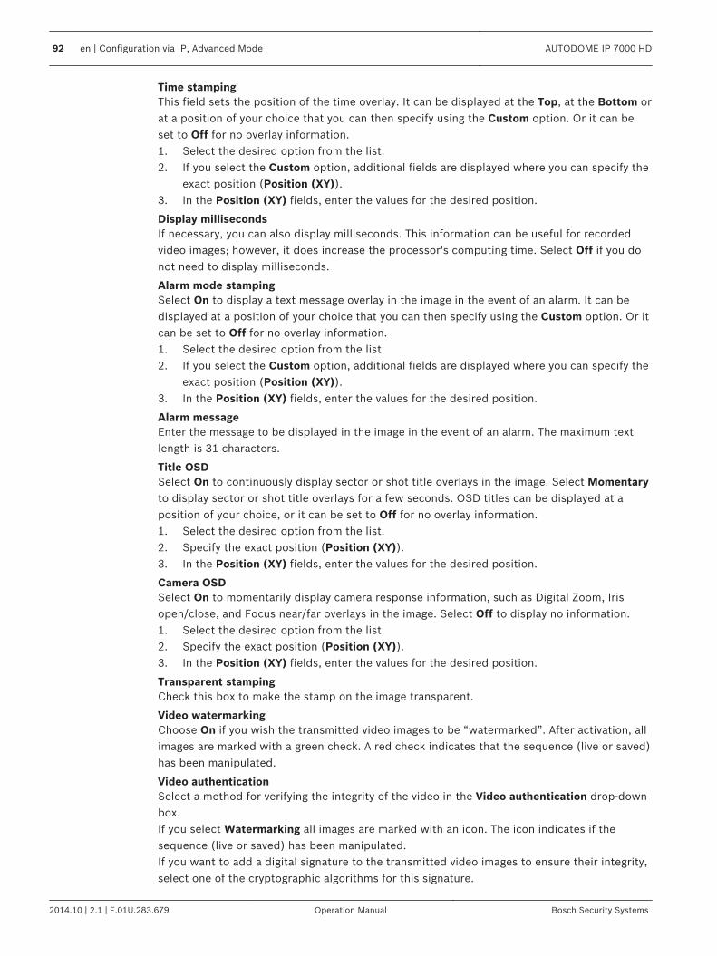
Time stampingThis field sets the position of the time overlay. It can be displayed at the Top, at the Bottom orat a position of your choice that you can then specify using the Custom option. Or it can beset to Off for no overlay information.1. Select the desired option from the list.2. If you select the Custom option, additional fields are displayed where you can specify the
exact position (Position (XY)).3. In the Position (XY) fields, enter the values for the desired position.
Display millisecondsIf necessary, you can also display milliseconds. This information can be useful for recordedvideo images; however, it does increase the processor's computing time. Select Off if you donot need to display milliseconds.
Alarm mode stampingSelect On to display a text message overlay in the image in the event of an alarm. It can bedisplayed at a position of your choice that you can then specify using the Custom option. Or itcan be set to Off for no overlay information.1. Select the desired option from the list.2. If you select the Custom option, additional fields are displayed where you can specify the
exact position (Position (XY)).3. In the Position (XY) fields, enter the values for the desired position.
Alarm messageEnter the message to be displayed in the image in the event of an alarm. The maximum textlength is 31 characters.
Title OSDSelect On to continuously display sector or shot title overlays in the image. Select Momentaryto display sector or shot title overlays for a few seconds. OSD titles can be displayed at aposition of your choice, or it can be set to Off for no overlay information.1. Select the desired option from the list.2. Specify the exact position (Position (XY)).3. In the Position (XY) fields, enter the values for the desired position.
Camera OSDSelect On to momentarily display camera response information, such as Digital Zoom, Irisopen/close, and Focus near/far overlays in the image. Select Off to display no information.1. Select the desired option from the list.2. Specify the exact position (Position (XY)).3. In the Position (XY) fields, enter the values for the desired position.
Transparent stampingCheck this box to make the stamp on the image transparent.
Video watermarkingChoose On if you wish the transmitted video images to be “watermarked”. After activation, allimages are marked with a green check. A red check indicates that the sequence (live or saved)has been manipulated.
Video authenticationSelect a method for verifying the integrity of the video in the Video authentication drop-downbox.If you select Watermarking all images are marked with an icon. The icon indicates if thesequence (live or saved) has been manipulated.If you want to add a digital signature to the transmitted video images to ensure their integrity,select one of the cryptographic algorithms for this signature.
92 en | Configuration via IP, Advanced Mode AUTODOME IP 7000 HD
2014.10 | 2.1 | F.01U.283.679 Operation Manual Bosch Security Systems

Enter the interval (in seconds) between insertions of the digital signature.
Advanced Mode: Web Interface
AppearanceOn this page you can adapt the appearance of the web interface and change the websitelanguage to meet your requirements. If necessary, you can replace the manufacturer's logo(top right) and the product name (top left) in the top part of the window with individualgraphics.
Notice!
You can use either GIF or JPEG images. The file paths must correspond to the access mode
(for example C:\Images\Logo.gif for access to local files, or http://www.mycompany.com/
images/logo.gif for access via the Internet/Intranet).
When accessing via the Internet/Intranet, ensure that a connection is always available to
display the image. The image file is not stored in the camera.
Website languageSelect the language for the user interface here.
Company logoEnter the path to a suitable graphic if you want to replace the manufacturer's logo. The imagefile can be stored on a local computer, in the local network or at an Internet address.
Device logoEnter the path to a suitable graphic if you want to replace the product name. The image filecan be stored on a local computer, in the local network or at an Internet address.
Notice!
If you want to use the original graphics again, simply delete the entries in the Company logo
and Device logo fields.
Show VCA metadataWhen video content analysis (VCA) is activated, additional information is displayed in the livevideo stream. For example, in Motion+ mode, the sensor areas for motion detection aremarked.
Show VCA trajectoriesWhen video content analysis (VCA) is activated, check this item to show additional informationthat traces the path of objects.
Show overlay iconsSelect this checkbox to show overlay icons on the live video image.
Video playerSelect the desired video player from the list in the drop-down box. Options are “Auto detect”(default), Bosch Video SDK, Bosch Autoload Decoder, JPEG
JPEG sizeYou can specify the size of the JPEG image on the LIVE page. Options are Small, Medium,Large, 720p, 1080p, and “Best possible” (default).
JPEG intervalYou can specify the interval at which the individual images should be generated for the M-JPEG image on the LIVE page.
JPEG qualityYou can specify the quality at which the JPEG images appear on the LIVE page.
14.6
14.7
AUTODOME IP 7000 HD Configuration via IP, Advanced Mode | en 93
Bosch Security Systems Operation Manual 2014.10 | 2.1 | F.01U.283.679

LIVE FunctionsOn this page you can adapt the functions on the LIVE page to your requirements. You canchoose from a variety of different options for displaying information and controls.1. Check the box for the items that are to be made available on the LIVE page. The selected
items are indicated by a check mark.2. Check whether the required functions are available on the LIVE page.
Transmit audioYou can only select this option if audio transmission is actually switched on (see Audio, page109).The audio signals are sent in a separate data stream parallel to the video data, and soincrease the network load. The audio data are encoded according to G.711 and require anadditional bandwidth of approx. 80 kbps per connection in each direction.
Lease time (s)The lease time in seconds determines the time beyond which a different user is authorized tocontrol the camera after no further control signals are received from the current user. Afterthis time interval, the camera is automatically enabled.
Show alarm inputsThe alarm inputs are displayed next to the video image as icons along with their assignednames. If an alarm is active, the corresponding icon changes color.
Show alarm outputsAlarm outputs are shown next to the video image as icons, along with their assigned names. Ifthe alarm output is active, the corresponding icon changes color.
Show event logThe event messages are displayed along with the date and time in a field next to the videoimage.
Show system logThe system messages are displayed along with the date and time in a field next to the videoimage and provide information about establishing and ending connections, for example.
Allow snapshotsHere you can specify whether the icon for saving individual images (snapshots) should bedisplayed below the live image. Individual images can only be saved if this icon is visible.
Allow local recordingHere you can specify whether the icon for saving (recording) video sequences on the localmemory should be displayed below the live image. Video sequences can only be saved if thisicon is visible.
I-frames only streamHere you can specify whether the LIVE page displays a viewing tab for an I-frame only stream.
Show scene listHere you can specify whether the View Controls section of the LIVE page displays a drop-down box with the list of scenes set in Advanced Mode > Camera > Scenes and Tours of theSETTINGS page.
Show ‘Intelligent Tracking’Here you can specify whether the LIVE page displays the controls for the Intelligent Trackingfeature.
Show ‘Special Functions’Here you can specify whether the LIVE page displays the Special Functions section.
Path for JPEG and video files1. Enter the path for the storage location of individual images and video sequences that you
can save from the LIVE page.
14.8
94 en | Configuration via IP, Advanced Mode AUTODOME IP 7000 HD
2014.10 | 2.1 | F.01U.283.679 Operation Manual Bosch Security Systems

2. If necessary, click Browse to find a suitable directory.
LoggingSave event logCheck this option to save event messages in a text file on your local computer. You can thenview, edit and print this file with any text editor or the standard Office software.
File for event log1. Enter the path for saving the event log here.2. If necessary, click Browse to find a suitable directory.
Save system logCheck this option to save system messages in a text file on your local computer. You can thenview, edit and print this file with any text editor or the standard Office software.
File for system log1. Enter the path for saving the system log here.2. If necessary, click Browse to find a suitable directory.
Advanced Mode: Camera
Installer MenuThe following options are available only for HD cameras:Base frame rateThis option allows you to set the frame rate that the camera uses to transmit video. Selecteither 25 ips or 30 ips. If you select 25 ips, the camera will stream video at 25 or 50 ips. If youselect 30 ips, the camera will stream video at 30 or 60 ips, depending on the option selectedin the Encoder Stream.Max. frame rateThis option determines the maximum frame rate that the camera streams video. Select one ofthe following options:
Max. Frame Rate Option Available Streaming Options
25/30 ips (up to 1920 x 1080) H.264 MP 720p25/30 FixedH.264 MP 1080p25/30 Fixed
50/60 ips (up to 1280 x 720) H.264 MP 720p50/60 Fixed
Notice!
Changing the Base frame rate or Max. frame rate
A change to the Base frame rate or to the Max. frame rate parameter requires a reboot of the
HD camera. The reboot process takes approximately 10-20 seconds. During this time, no
changes can be made. The cameo image freezes.
This section also displays a graphic that shows the relative image size difference between animage encoded at 1280 x 720 and at 1920 x 1080.
OrientationReverses the image 180º (ideal when mounting upside down). Set the orientation to Normal(default) or Inverted.
14.9
14.10
14.11
AUTODOME IP 7000 HD Configuration via IP, Advanced Mode | en 95
Bosch Security Systems Operation Manual 2014.10 | 2.1 | F.01U.283.679

!
Caution!
The camera disables the Privacy Mask function if the orientation is set to Inverted.
SC settingsClick the Default button to restore all camera settings to their original defaults.
SC dataClick the Default button to clear all prepositions, privacy masks, and other configurationsettings defined in the camera’s web server to their default values.
Reboot deviceClick the Reboot button to reboot the camera. There is a ten (10) second pause before thedome starts its homing phase. During the homing phase, the camera pans left and right andtilts up and down. It also adjusts the lens focus. The entire homing phase lasts approximately40 seconds.
Factory defaultsClick the Defaults button to restore the configuration settings defined in the camera’s webserver to their default values. A confirmation screen appears. Allow 5 seconds for the camerato optimize the picture after a mode reset.
96 en | Configuration via IP, Advanced Mode AUTODOME IP 7000 HD
2014.10 | 2.1 | F.01U.283.679 Operation Manual Bosch Security Systems

Encoder Profile
Figure 14.1: Advanced Mode>Camera>Encoder Profile>Profile 1 [HD models only]
For the video signal encoding, you can select a code algorithm and you can change the presetsfor the profiles.You can adapt the video data transmission to the operating environment (for example networkstructure, bandwidth, data load). To this end, the camera simultaneously generates two datastreams (Dual Streaming), which compression settings you can select individually, for exampleone setting for transmissions to the Internet and one for LAN connections.Pre-programmed profiles are available, each giving priority to different perspectives.You can change individual parameter values of a profile and you can also change the name.You can switch between profiles by clicking the appropriate tabs.
!
Caution!
The profiles are rather complex. They include a large number of parameters that interact with
one another, so it is generally best to use the default profiles.
Change the profiles only once you are fully familiar with all the configuration options.
14.12
AUTODOME IP 7000 HD Configuration via IP, Advanced Mode | en 97
Bosch Security Systems Operation Manual 2014.10 | 2.1 | F.01U.283.679

Notice!
In the default setting, Stream 1 is transmitted for alarm connections and automatic
connections. Keep this fact in mind when assigning the profile.
Notice!
All parameters combine to make up a profile and are dependent on one another. If you enter a
setting that is outside the permitted range for a particular parameter, the nearest permitted
value will be substituted when the settings are saved.
HD Profiles (Configuration Parameters)
HD Image OptimizedTarget bit rate: 2000 kbpsMaximum bit rate: 4000 kbpsEncoding interval: 30.00 ips
HD BalancedTarget bit rate: 4000 kbpsMaximum bit rate: 7000 kbpsEncoding interval: 30.00 ips
HD Bit Rate OptimizedTarget bit rate: 2500 kbpsMaximum bit rate: 4500 kbpsEncoding interval: 30.00 ips
SD Image OptimizedTarget bit rate: 3300 kbpsMaximum bit rate: 5000 kbpsEncoding interval: 30.00 ips
SD BalancedTarget bit rate: 1300 kbpsMaximum bit rate: 2600 kbpsEncoding interval: 30.00 ips
SD Bit Rate OptimizedTarget bit rate: 750 kbpsMaximum bit rate: 1500 kbpsEncoding interval: 30.00 ips
DSL OptimizedTarget bit rate: 380 kbpsMaximum bit rate: 500 kbpsEncoding interval: 30.00 ips
3G OptimizedTarget bit rate: 80 kbpsMaximum bit rate: 100 kbpsEncoding interval: 30.00 ips
Profile nameIf required, enter a new name for the profile.
98 en | Configuration via IP, Advanced Mode AUTODOME IP 7000 HD
2014.10 | 2.1 | F.01U.283.679 Operation Manual Bosch Security Systems

Target bit rateTo optimize use of the bandwidth in the network, limit the data rate for the device. The targetdata rate should be set according to the desired picture quality for typical scenes with noexcessive motion.For complex images or frequent changes of image content due to frequent movements, thislimit can temporarily be exceeded up to the value entered in the Maximum bit rate field.
Maximum bit rateThis maximum bit rate is not exceeded under any circumstances. Depending on the videoquality settings for the I- and P-frames, this fact can result in individual images being skipped.The value entered here must be at least 10% higher than the value entered in the Target bitrate field. If the value entered here is too low, it will be adjusted automatically.
Encoding intervalThis parameter determines the interval at which images are encoded and transmitted. Forexample, entering or selecting 4 means that only every fourth image is encoded, while thefollowing there are skipped, which can be particularly advantageous for networks with lowbandwidths. The image rate in (images per second (ips) appears next to the text field orslider.
Video resolutionSelect the desired resolution for the video image.For standard definition only, options are:– 240p– 480p– 144p– 288p– 432p (default)
Expert SettingsIf necessary, use the expert settings to adapt the I-frame quality and the P-frame quality tospecific requirements. The setting is based on the H.264 quantization parameter (QP).
GOP structureSelect the structure that you require for the group of pictures, depending on whether youplace greater priority on having the lowest possible delay (IP frames only) or using as littlebandwidth as possible.Options are IP, IBP, and IBBP.GOP is not available for megapixel cameras.
I-frame distanceThis parameter allows you to set the intervals in which the I-frames will be coded. Auto meansauto mode, whereby the video server inserts I-frames as necessary. Values range from 3 to 60.An entry of 3 indicates that I-frames are continuously generated. An entry of 4 indicates thatonly every fourth image is an I-frame, and so on; the frames in between are coded as P-frames.Note that the values supported depend on the GOP structure setting. For example, only evenvalues are supported with IBP; if you have selected IBBP, only 3 or multiples of 3 aresupported.
Min. P-frame QPThis parameter allows you to adjust the image quality of the P-frame and to define the lowerlimit for the quantization of the P-frames, and thus the maximum achievable quality of the P-frames. In the H.264-protocol, the Quantization Parameter (QP) specifies the degree ofcompression and thus the image quality for every frame. The lower the quantization of the P-frame (QP value), the higher the encoding quality (and thus the best image quality) and the
AUTODOME IP 7000 HD Configuration via IP, Advanced Mode | en 99
Bosch Security Systems Operation Manual 2014.10 | 2.1 | F.01U.283.679

lower the frame refresh rate depending on the settings for the maximum data rate undernetwork settings. A higher quantization value results in low image quality and lower networkload. Typical QP values are between 18 and 30.The basic setting Auto automatically adjusts the quality to the settings for the P-frame videoquality.
I/P-frame delta QPThis parameter sets the ratio of the I-frame quantization (QP) to the P-frame quantization(QP). For example, you can set a lower value for I-frames by moving the slide control to anegative value. Thus, the quality of the I-frames relative to the P-frames is improved. The totaldata load will increase, but only by the portion of I-frames. The basic setting Autoautomatically adjusts to the optimum combination of movement and image definition (focus).To obtain the highest quality at the lowest bandwidth, even in the case of increasedmovement in the picture, configure the quality settings as follows:1. Observe the coverage area during normal movement in the preview images.2. Set the value for Min. P-frame QP to the highest value at which the image quality still
meets your needs.3. Set the value for I/P-frame delta QP to the lowest possible value. This is how to save
bandwidth and memory in normal scenes. The image quality is retained even in the caseof increased movement since the bandwidth is then filled up to the value that is enteredunder Maximum bit rate.
DefaultClick Default to return the profile to the factory default values.
Encoder StreamsPropertySelect one of the H.264 standards for each stream.
Stream 1 (recording) Options are:- H.264 MP SD- H.264 MP 720p25/30 Fixed- H.264 MP 1080p25/30 Fixed;- H.264 MP 720p50/60 Fixed
Note: In order to select the option “H.264 MP 720p50/60 Fixed” here, you must set the Max.frame rate field in the Advanced Mode: Camera >Installer Menu to “H.264 MP 720p50/60Fixed” first.Note (for dynamic models only): In order to select the option “H.264 MP 1080p25/30 Fixed”here, you must set the Max.frame rate field in the Advanced Mode: Camera >Installer Menu to“H.264 MP 1080p25/30 Fixed” first.
Stream 2 Options vary depending on Stream 1 selection.
Options with “H.264 MP 1080p25/30 Fixed” selected forStream 1:– Copy Stream 1– H.264 MP SD– H.264 MP 720p8/10 Fixed– H.264 MP 1080p4/5 Fixed– H.264 MP upright (cropped)– H.264 MP D1 4:3 (cropped)
14.13
100 en | Configuration via IP, Advanced Mode AUTODOME IP 7000 HD
2014.10 | 2.1 | F.01U.283.679 Operation Manual Bosch Security Systems

Options with “H.264 MP 720p50/60 Fixed” selected forStream 1:– Copy Stream 1– H.264 MP SD– H.264 MP 720p6/7 Fixed– H.264 MP upright (cropped)– H.264 MP D1 4:3 (cropped)
Options with “H.264 MP 720p25/30 Fixed” selected forStream 1:– H.264 MP SD– H.264 MP 720p25/30 Fixed– H.264 MP upright (cropped)– H.264 MP D1 4:3 (cropped)– H.264 MP 1280x960 (cropped)
Option with “H.264 MP SD” selected for Stream 1: H.264 MPSD
Non-recording profileSelect one of the following profiles for each stream:
HD Profiles (Configuration Parameters)
HD Image OptimizedTarget bit rate: 2000 kbpsMaximum bit rate: 4000 kbpsEncoding interval: 30.00 ips
HD BalancedTarget bit rate: 4000 kbpsMaximum bit rate: 7000 kbpsEncoding interval: 30.00 ips
HD Bit Rate OptimizedTarget bit rate: 2500 kbpsMaximum bit rate: 4500 kbpsEncoding interval: 30.00 ips
SD Image OptimizedTarget bit rate: 3300 kbpsMaximum bit rate: 5000 kbpsEncoding interval: 30.00 ips
SD BalancedTarget bit rate: 1300 kbpsMaximum bit rate: 2600 kbpsEncoding interval: 30.00 ips
SD Bit Rate OptimizedTarget bit rate: 750 kbpsMaximum bit rate: 1500 kbpsEncoding interval: 30.00 ips
AUTODOME IP 7000 HD Configuration via IP, Advanced Mode | en 101
Bosch Security Systems Operation Manual 2014.10 | 2.1 | F.01U.283.679

HD Profiles (Configuration Parameters)
DSL OptimizedTarget bit rate: 380 kbpsMaximum bit rate: 500 kbpsEncoding interval: 30.00 ips
3G OptimizedTarget bit rate: 80 kbpsMaximum bit rate: 100 kbpsEncoding interval: 30.00 ips
PreviewClick the Preview button to open a small static preview window for each stream. To enlargethe preview and view live video, click the 1:1 Live View button.
JPEG streamSelect the resolution, frame rate, and image quality parameters for the M-JPEG stream.– Resolution: Select the appropriate resolution.– Max. frame rate: Select one of the following frame rates to be the maximum: 5, 10, 15,
20, 25, or 30 ips.– Picture quality: This setting allows you to adjust the image quality. Use the slide bar to
choose a quality between Low and High. Note: The M-JPEG frame rate can vary depending on system loading.
See also– Encoder Profile, page 97
Privacy MasksPrivacy Masking is used to block out a specific area of a scene from being viewed. Masks canbe configured as a gray area with four corners. You may define a total of 24 privacy masks.To add a privacy mask to a scene:1. Navigate to the scene in which you want to apply a privacy mask.
Click the View Control link.Use the PTZ controls to view the scene.
2. Select the privacy mask number to apply to the scene.3. The preview window displays a gray rectangle in the scene.4. Click the Enabled check box to activate the privacy mask.5. The privacy mask in the preview window changes to orange to indicate that the mask will
appear in the video streams on the LIVE page.6. Place the cursor inside the privacy mask area in the preview window; then click and drag
to move the privacy mask.7. Place the cursor on a corner or on a vertex of the mask rectangle; then click and drag to
expand or shrink the privacy mask area.8. Click Set to save the privacy mask size and position.
An image window displays the privacy mask.9. To hide an individual mask, select the mask number and clear the Enabled check box.10. To hide all masks from an image view, click the Disable Masks check box.
Note: If you choose to hide all masks, you must enable each individual mask to show themask in the scene.
11. To display IVA behind privacy masks, click the IVA behind masks check box.
14.14
102 en | Configuration via IP, Advanced Mode AUTODOME IP 7000 HD
2014.10 | 2.1 | F.01U.283.679 Operation Manual Bosch Security Systems

Notice!
Draw the mask 10% larger than the object to ensure that the mask completely covers the
object as the camera zooms in and out. Click the Zoom threshold box.
Draw the mask at 50% optical zoom or less for improved masking performance.
Notice!
The camera disables the Privacy Mask feature if the orientation of the camera is set to
Inverted. Refer to Installer Menu, page 95 for orientation settings.
See also– Installer Menu, page 95
Picture SettingsCurrent modeSelect one of the pre-programmed user modes, optimized with the best settings for a varietyof typical applications, that best defines the environment in which the camera is installed.– Outdoor – General day-to-night changes with sun highlights and street lighting– Indoor – Ideal mode for indoor applications where lighting is constant and not changing– Low light – Optimized for sufficient details at low light– Motion – Monitoring traffic or fast moving objects; motion artifacts are minimized– Vibrant – Enhanced contrast color reproduction and sharpnessThe default setting depends on whether the camera is an in-ceiling camera or a pendantcamera.Customize the mode, if necessary, for the specific requirements of the site by selectingdifferent values for the fields below.In this case, the name of the user mode changes to “Custom.”
White BalanceAdjusts the color settings to maintain the quality of the white areas of the image.– ATW: allows the camera to continuously adjust color reproduction.– AWB Hold: places the ATW on hold and saves the color settings.– Extended ATW (default): allows the camera to constantly adjust for optimal color
reproduction.– Manual: Red and Blue gain can be manually set to a desired position.– Sodium Lamp Auto: Automatically adjusts for sodium vapor light to restore objects to
their original color.– Sodium Lamp: Optimizes the sodium vapor light to restore objects to their original color.
Red GainThe red gain adjustment offsets the factory white point alignment (reducing red introducesmore cyan).
Blue GainThe blue gain adjustment offsets the factory white point alignment (reducing blue introducesmore yellow). It is only necessary to change the white point offset for special sceneconditions.
SaturationThe percentage of light or color in the video image (HD only). Values range from 60% to 200%;the default is 110%.
14.15
AUTODOME IP 7000 HD Configuration via IP, Advanced Mode | en 103
Bosch Security Systems Operation Manual 2014.10 | 2.1 | F.01U.283.679

Color hueThe degree of color in the video image (HD only). Values range from -14° to 14°; the default is8°.
Gain controlAdjusts the automatic gain control (AGC). Automatically sets the gain to the lowest possiblevalue needed to maintain a good picture.– AGC (default): electronically brightens dark scenes, which may cause graininess in low
light scenes.– Fixed: no enhancement. This setting disables the Max. Gain Level option.
If you select this option, the camera makes the following changes automatically:– Night Mode: switches to Color– Auto Iris: switches to Constant
Fixed GainUse the slide to select the desired number for fixed gain. The default is 2.
Maximum Gain LevelControls the maximum value the gain can have during AGC operation. To set the maximumgain level, choose from:– Normal– Medium– High (default)
AE-response speedSelect the speed of the response of auto exposure. Options are Super slow, Slow, Medium(default), Fast.
SharpnessAdjusts the sharpness of the picture. To set the sharpness, use the slider to select a number.The default is 12.
Shutter Mode– Off: turns the Auto SensUP Off.– AutoSensUp: increases camera sensitivity by increasing the integration time on the
camera. This is accomplished by integrating the signal from a number of consecutivevideo frames to reduce signal noise.If you select this option, the camera makes the following change automatically:– Auto Iris: switches to Constant– Shutter: is disabled
ShutterAdjusts the electronic shutter speed (AES). Controls the time period for which light isgathered by the collecting device. The default setting is 1/60 second for NTSC and 1/50 forPAL cameras. The range of settings is from 1/1 to 1/10000.
Auto SensUP limitThis is the maximum shutter speed when Auto SensUP (Frame Integration) is active. Thedefault is 1/4. The range of settings is from 1/4 to 1/30.
Shutter limitThe camera tries to hold this shutter value as long as sufficient ambient light is available in thescene.Settings range from 1/1 to 1/10000. The default value is 1/2000 for all modes except 'Motion'(default 1/500).
104 en | Configuration via IP, Advanced Mode AUTODOME IP 7000 HD
2014.10 | 2.1 | F.01U.283.679 Operation Manual Bosch Security Systems

Backlight compensationOptimizes the video level for the selected area of the image. Parts outside this area may beunderexposed or overexposed. Select On to optimize the video level for the central area of theimage. The default setting is Off.
High SensitivityAdjusts the level of intensity or lux within the image (HD only). Select from Off or On.Note: In Black and White (Night) mode / low light situations, High Sensitivity turns onautomatically.
StabilizationThis feature is ideal for cameras mounted on a pole or mast, or on another location thatshakes frequently.Select On to activate the video stabilization feature (if available on your camera) that reducescamera shake in both the vertical and horizontal axis. The camera compensates for themovement of the image by up to 2% of the image size.Select Auto to activate the feature automatically when the camera detects vibration.Select Off to deactivate the feature.Note: This feature is not available on 20x models.
High dynamic rangeSelect On to activate wide dynamic range, which improves image reproduction in extremehigh-contract scenes.Select Off to deactivate the feature.Select Enhanced to activate high dynamic range when the camera detects an extreme high-contract scene. The camera makes multiple, simultaneous exposures of the same scene tocapture details in both bright and dark parts of the scene.
Night modeSelects night mode (B/W) to enhance lighting in low light scenes. Select from the followingoptions:– Monochrome: Forces the camera to stay in Nigh Mode and transmit monochrome images.– Color: The camera does not switch to Night Mode regardless of ambient light conditions.– Auto (default): The camera switches out of Night Mode after the ambient light level
reaches a pre-defined threshold.
Night mode thresholdAdjusts the level of light at which the camera automatically switches out of night mode (B/W)operation. Select a value between 10 and 55 (in increments of 5), where 10 is earlier and 55 islater.
Noise ReductionTurns on the 2D and 3D noise reduction feature.
Noise Reduction LevelAdjusts the noise level to the appropriate level for shooting conditions. Select a value between1 and 5.
Anti-fogSelect Auto to configure the camera for automatic Anti-fog mode, which activates when thevideo analytics in the camera detect fog and add light to the video image (and thendeactivates when the fog clears or the scene changes).Select On to activate Anti-fog mode on a continuous basis. The camera operates in this modeuntil a user deactivates the mode. The video image on the LIVE page may become lighter.Select Off to deactivate the mode. The video image on the LIVE page may become darker.
AUTODOME IP 7000 HD Configuration via IP, Advanced Mode | en 105
Bosch Security Systems Operation Manual 2014.10 | 2.1 | F.01U.283.679

Lens SettingsAutofocusContinuously adjusts the lens automatically to the correct focus for the sharpest picture.– One Push (default; commonly called “Spot Focus”): activates the Auto Focus feature after
the camera stops moving. Once focused, Auto Focus is inactive until the camera is movedagain.
– Auto Focus: Auto Focus is always active.– Manual: Auto Focus is inactive.
Focus polarity– Normal (default): focus controls operate normally.– Reverse: focus controls are reversed.
Focus speedUse the slider (from 1 to 8) to control how fast the Auto focus will readjust when the focusbecomes blurred.
Auto irisAutomatically adjusts the lens to allow the correct illumination of the camera sensor. This typeof lens is recommended for use where there are low light or changing light conditions.– Constant (default): camera constantly adjusts to varying light conditions (default).
If you select this option, the camera makes the following changes automatically:– Gain Control: switches to AGC.– Shutter Speed: switches to default.
– Manual: camera must be manually adjusted to compensate for varying light conditions.
Iris polarityCapability to reverse the operation of the iris button on the controller.– Normal (default): iris controls operate normally.– Reverse: iris controls are reversed.
Auto iris levelIncreases or decreases brightness according to the amount of light. Type a value between 1and 15.
Maximum zoom speedControls the zoom speed.
Zoom polarityCapability to reverse the operation of the zoom button on the controller.– Normal (default): zoom controls operate normally.– Reverse: zoom controls are reversed.
Digital zoomDigital zoom is a method of decreasing (narrowing) the apparent angle of view of a digitalvideo image. It is accomplished electronically, without any adjustment of the camera's optics,and no optical resolution is gained in the process. Select Off to disable or On to enable thisfeature. The default setting is On.
PTZ SettingsAuto pan speedContinuously pans the camera at a speed between right and left limit settings. Type a valuebetween 1 and 60 (expressed in degrees), inclusive. The default setting is 30.
InactivitySelects the time period the dome must be not controlled until the inactivity event will beexecuted.– Off (default): camera remains on a current scene indefinitely.
14.16
14.17
106 en | Configuration via IP, Advanced Mode AUTODOME IP 7000 HD
2014.10 | 2.1 | F.01U.283.679 Operation Manual Bosch Security Systems

– Scene 1: camera returns to Preset 1.– Previous Aux: camera returns to the previous activity.
Inactivity periodDetermines the behavior of the dome when the control for dome is inactive. Select a timeperiod from the pull-down list (3 sec. - 10 min.). The default setting is 2 minutes.
Auto pivotThe Auto pivot tilts the camera through the vertical position as the camera is rotated tomaintain the correct orientation of the image. Set the Auto Pivot to On (default) toautomatically rotate the camera 180º when following a subject traveling directly beneath thecamera. To disable this feature, click Off.
Freeze frameSelect On to freeze the image while the camera moves to a predetermined scene position.
Turbo modeSelect On to set the camera in Turbo mode when an operator pans or tilts the cameramanually. In this mode, the camera can pan at a maximum of 400° per second, and tilt at amaximum of 300° per second.
Tracker Zoom Threshold [%]This parameter defines the zoom ratio percentage to which the camera zooms out afterTracker Timeout stops tracking, or if Intelligent Tracking loses visibility of an object beingtracked. This allows the camera to re-acquire the target in a new wider FoV. Settings rangefrom 0 to 100. The default is 50.
Tracker Timeout [sec]This parameter allows the camera to stop tracking motion of certain objects, such as a tree ora flag swaying in the wind, in a confined area after the specified number of seconds. Settingsrange from 5 to 120. The default is 30.
Auto pan left limitSets the left Auto Pan limit of the camera. Use the preview window to move the camera to theleft pan limit and click the button. The camera will not move past this limit when in Auto PanBetween Limits mode (AUX 2 ON).
Auto pan right limitSets the right Auto Pan limit of the camera. Use the preview window to move the camera tothe right pan limit and click the button. The camera will not move past this limit when in AutoPan Between Limits mode (AUX 2 ON).
Tilt up limitSets the upper tilt limit of the camera. Use the preview window to move the camera to the tiltlimit and click the button.
Tilt limitsClick the Reset button to clear the upper tilt limit.
Tour A / Tour BStarts and stops the recording of a recorded (guard) tour.The camera can make up to two (2) recorded tours. A recorded tour saves all manual cameramovements made during the recording, including its rate of pan, tilt and zoom speeds, andother lens setting changes. The tour does not capture camera video during the recording ofthe tour.Note 1: You can save a total of 15 minutes of recorded actions between the two tours.To record a tour:1. Click the Start Recording button. The system prompts you to overwrite the existing tour.2. Click Yes to overwrite the existing tour movements.
AUTODOME IP 7000 HD Configuration via IP, Advanced Mode | en 107
Bosch Security Systems Operation Manual 2014.10 | 2.1 | F.01U.283.679

3. Click the View Control link, under the image cameo, to access the directional and zoomcontrols.
4. Use the View Control dialog box to make the necessary camera movements.5. Click the Stop Recording button to save all actions.
North pointClick the Set button to overwrite the existing North point.Click the Defaults button to reset the North point to factory defaults.
Scenes and ToursThe camera can store up to 256 preset scenes. You can define the individual scenes thatcomprise a preposition tour.You define individual preposition scenes, then use these scenes to define the preposition tour.The tour starts from the lowest scene number in the tour and progresses sequentially to thehighest scene number in the tour. The tour displays each scene for a specified dwell timebefore advancing to the next scene.By default, all scenes are part of the preposition tour unless removed.
To define and edit an individual scene:1. Click the View Control link.
Use the PTZ controls to move the camera into position.Navigate to the scene that you want to define as a preposition.
2. Click the Add scene (“+”) button to define the preposition.3. Select a number for the scene, from 1 to 256.4. Type an optional name for the scene, up to 20 characters long.5. Click OK to save the scene to the Preposition list.
The asterisk (*) to the left of the scene name indicates the scene is part of thepreposition tour.
6. To delete a scene from the list, select the scene and click the Delete scene (“X”) button.7. To overwrite an existing scene:
Click the View Control link to access the PTZ controls.Use the PTZ controls to navigate to the new scene.Click the scene in the Preposition list you want to overwrite.Click the Overwrite scene button to apply the new scene to the existing preposition.To change the name of the scene, double-click the scene in the list. Then, change thename in the Edit Scene dialog box and click OK.
8. To view a scene in the preview window, select the scene in the list and click the Showscene button.
9. To view a scene from the LIVE page:Click a scene number below the PTZ controls on the View Control tab.ORUse the keypad and the Show Shot button on the Aux Control tab.
To define a preposition tour:1. Create the individual scenes.
By default, all scenes in the Preposition list are in the preposition tour.2. To remove a scene from the tour, select the scene in the list and uncheck the Include in
standard tour box.3. Select a dwell time from the Standard preposition tour drop-down list.4. To start the preposition tour:
Return to the LIVE page.Click the Aux Control tab.
14.18
108 en | Configuration via IP, Advanced Mode AUTODOME IP 7000 HD
2014.10 | 2.1 | F.01U.283.679 Operation Manual Bosch Security Systems

Type 8 in the input box and click the Aux On button.5. To stop the tour, type 8 and click the Aux Off button.
Notice!
Refer to the document “AUTODOME_OperationGuidelines_2014.pdf” for guidelines for
operating your camera using Guard Tours and Preset Tours. To access the document, go to
www.boschsecurity.com, navigate to the product page for your camera, and then locate the
document in the Documents tab.
SectorsSectorThe camera’s pan capability is 360° and is divided into 16 equal sectors. This section allowsyou to apply a title for each sector and to designate any sectors as a Blanked Sector.
To define a title for sectors:1. Place the cursor in the input box to the right of the sector number.2. Type a title for the sector, up to 20 characters long.3. To blank the sector, click the check box to the right of the sector title.
MiscellaneousFast addressThis parameter allows the appropriate camera to be operated via the numerical address in thecontrol system. Enter a number between 0000 and 9999, inclusive, to identify the camera.Note: This is required for identifying cameras connected through a decoder such as theVIDEOJET decoder 3000 (VJD-3000).
LogsTo save the log file information:1. Click Download to obtain the log information.2. Click Save.3. Navigate to the directory in which you want to store the log information.4. Type a name for the log file and click Save.
AudioYou can set the gain of the audio signals to suit your specific requirements. The current videoimage is shown in the small window next to the slide controls to help you check the audiosource and improve assignments. Your changes are effective immediately.If you connect via Web browser, you must activate the audio transmission on the LIVEFunctions page. (See LIVE Functions, page 94.) For other connections, the transmissiondepends on the audio settings of the respective system.
AudioThe audio signals are sent in a separate data stream parallel to the video data, and so increasethe network load. The audio data are encoded according to G.711 and require an additionalbandwidth of approximately 80 kbps for each connection. If you do not want any audio data tobe transmitted, select Off.
Input volumeYou can set the input volume with the slider (from 0 to 31, with 0 as the default).
Line InYou can set the line input gain with the slider (from 0 (zero) to 79, with 0 as the default).Make sure that the display does not go beyond the green zone during modulation.
14.19
14.20
14.21
14.22
AUTODOME IP 7000 HD Configuration via IP, Advanced Mode | en 109
Bosch Security Systems Operation Manual 2014.10 | 2.1 | F.01U.283.679

Line OutYou can set the line output gain with the slider (from 0 (zero) to 79, with 0 as the default).Make sure that the display does not go beyond the green zone during modulation.
Recording formatSelect a format for audio recording. Select L16 or AAC (Advanced Audio Coding) if you wantbetter audio quality with higher sampling rates. Note that the L16 standard requiresapproximately eight times the bandwidth of the format G.711.
Pixel CounterCounts the number of pixels in a defined image area. The pixel counter allows the installer toeasily verify that the camera installation fulfills any regulatory or specific customerrequirements, for example, calculating the pixel resolution of the face of a person passing adoorway monitored by the camera.
Advanced Mode: Recording
Storage ManagementYou can record the images from the camera on various local storage media (user-supplied SD,SDHC, or SDXC memory card) or on an appropriately configured iSCSI system.It is also possible to let the VRM Video Recording Manager control all recording with accessingan iSCSI system. This is an external program for configuring recording tasks for video servers.For further information please contact your local customer service at Bosch Security SystemsInc.
Device managerIf you activate the Managed by VRM option in this screen, the VRM Video Recording Managerwill manage all recording and you will not be able to configure any further settings here.
!
Caution!
Activating or deactivating VRM causes the current settings to be lost; they can only be
restored through reconfiguration.
Recording mediaSelect the required recording media here so that you can then activate them and configure therecording parameters.
iSCSI MediaIf you want to use an iSCSI system as a recording medium, you must set up a connection tothe required iSCSI system and set the configuration parameters.
Notice!
The iSCSI storage system selected must be available on the network and completely set up.
Amongst other things, it must have an IP address and be divided into logical drives (LUN).
14.23
14.24
14.25
110 en | Configuration via IP, Advanced Mode AUTODOME IP 7000 HD
2014.10 | 2.1 | F.01U.283.679 Operation Manual Bosch Security Systems

1. Enter the IP address of the required iSCSI destination in the iSCSI IP address field.2. If the iSCSI destination is password protected, enter this into the Password field.3. Click the Read button. The connection to the IP address will be established. In the
Storage overview field, you can see the corresponding logical drives.
Local MediaThe supported local recording media are displayed in the Storage overview field.
Activating and Configuring Storage MediaThe storage overview displays the available storage media. You can select individual media oriSCSI drives and transfer these to the Managed storage media list. You can activate thestorage media in this list and configure them for storage.
!
Caution!
Each storage medium can only be associated with one user. If a storage medium is already
being used by another user, you can decouple the user and connect the drive with the
camera. Before decoupling, make absolutely sure that the previous user no longer needs the
storage medium.
1. In the Recording media section, click the iSCSI Media and Local Media tabs to displaythe applicable storage media in the overview.
2. In the Storage overview section, double-click the required storage medium, an iSCSI LUNor one of the other available drives. The medium is then added to the Managed storagemedia list. In the Status column, newly added media are indicated by the status Notactive.
3. Click the Set button to activate all media in the Managed storage media list. In theStatus column, these are indicated by the status Online.
4. Check the box in the Rec. 1 or Rec. 2 to specify which data stream should be recordedon the storage media selected. Rec. 1 stores Stream 1, Rec. 2 stores Stream 2. Thismeans that you can record the standard data stream on a hard drive and record alarmimages on the mobile CF card, for example.
5. Check the boxes for the Overwrite older recordings option to specify which olderrecordings can be overwritten once the available memory capacity has been used.Recording 1 corresponds to Stream 1, Recording 2 corresponds to Stream 2.
!
Caution!
If older recordings are not allowed to be overwritten when the available memory capacity has
been used, the recording in question will be stopped. You can specify limitations for
overwriting old recordings by configuring the retention time (see Maximum Retention Time,
page 113).
Formatting Storage MediaYou can delete all recordings on a storage medium at any time.
!
Caution!
Check the recordings before deleting and back up important sequences on the computer's
hard drive.
1. Click a storage medium in the Managed storage media list to select it.2. Click the Edit button below the list. A new window will open.3. Click the Formatting button to delete all recordings in the storage medium.4. Click OK to close the window.
AUTODOME IP 7000 HD Configuration via IP, Advanced Mode | en 111
Bosch Security Systems Operation Manual 2014.10 | 2.1 | F.01U.283.679

Deactivating Storage MediaYou can deactivate any storage medium from the Managed storage media list. It is then nolonger used for recordings.1. Click a storage medium in the Managed storage media list to select it.2. Click the Remove button below the list. The storage medium is deactivated and removed
from the list.
Recording ProfilesYou can define up to ten different recording profiles. You will then use these recording profilesin the recording scheduler, where they are linked with the individual days and times (seeRecording Scheduler, page 113).
Notice!
You can change or add to the recording profile description on the tabs on the Recording
Scheduler page (see Recording Scheduler, page 113).
1. Click one of the tabs to edit the corresponding profile.2. If necessary, click the Default button to return all settings to their default values.3. Click the Copy Settings button if you want to copy the currently visible settings to other
profiles. A new window will open and you can select the profiles in which you want tocopy the settings.
4. For each profile, click the Set button to save the settings in the unit.
Standard recordingHere you can select the mode for standard recordings.If you select Continuous, the recording proceeds continuously. If the maximum memorycapacity is reached, older recordings will automatically be overwritten. If you select the Pre-alarm option, recording will only take place in the pre-alarm time, during the alarm and duringthe set post-alarm time.If you select Off, no automatic recording takes place.
!
Caution!
You can specify limitations for overwriting older recordings in Continuous mode by
configuring the retention time (see Maximum Retention Time, page 113).
Standard profileFrom this field, you can select the encoder profile to be used for recording (see EncoderProfile, page 97).
Notice!
The recording profile can deviate from the standard setting Active profile and is only used
during an active recording.
Pre-alarm timeYou can select the required pre-alarm time from the list field.
Post-alarm timeYou can select the required post-alarm time from the list field.
Post-alarm profileYou can select the encoder profile to be used for recording during the post-alarm time (seeEncoder Profile, page 97).The Standard profile option adopts the selection at the top of the page.
14.26
112 en | Configuration via IP, Advanced Mode AUTODOME IP 7000 HD
2014.10 | 2.1 | F.01U.283.679 Operation Manual Bosch Security Systems

Alarm input / Analysis alarm / Video loss alarmHere you can select the alarm sensor that is to trigger a recording.
Virtual alarmHere you can select the virtual alarm sensors that are to trigger a recording, via RCP+commands or alarm scripts, for example.
Notice!
For more information, please see the Alarm Task Script Language document and the RCP+
documentation. These documents can be found on the product CD supplied.
Recording includesYou can specify whether, in addition to video data and metadata (for example alarms, VCAdata and serial data) should also be recorded. Including metadata could make subsequentsearches of recordings easier but it requires additional memory capacity.
!
Caution!
Without metadata, it is not possible to include video content analysis in recordings.
Maximum Retention TimeYou can specify the retention times for recordings. If the available memory capacity of amedium has been used, older recordings are only overwritten if the retention time enteredhere has expired.
Notice!
Make sure that the retention time corresponds with the available memory capacity. A rule of
thumb for the memory requirement is as follows: 1 GB per hour retention time with 4CIF for
complete frame rate and high image quality.
Maximum Retention TimeEnter the required retention time in hours or days for each recording. Recording 1corresponds to Stream 1, Recording 2 corresponds to Stream 2.
Recording SchedulerThe recording scheduler allows you to link the created recording profiles with the days andtimes at which the camera's images are to be recorded in the event of an alarm.You can link any number of 15-minute intervals with the recording profiles for each day of theweek. Moving the mouse cursor over the table displays the time below it. This aids orientation.In addition to the normal weekdays, you can define holidays that are not in the standardweekly schedule on which recordings are to apply. This allows you to apply a schedule forSundays to other days with dates that fall on varying weekdays.1. Click the profile you want to link in the Time periods field.2. Click in a field in the table, hold down the mouse button and drag the cursor over all the
periods to be assigned to the selected profile.3. Use the right mouse button to deselect any of the intervals.4. Click the Select All button to link all time intervals to the selected profile.5. Click the Clear All button to deselect all of the intervals.6. When you are finished, click the Set button to save the settings in the unit.
14.27
14.28
AUTODOME IP 7000 HD Configuration via IP, Advanced Mode | en 113
Bosch Security Systems Operation Manual 2014.10 | 2.1 | F.01U.283.679

HolidaysYou can define holidays that are not in the standard weekly schedule on which recordings areto apply. This allows you to apply a schedule for Sundays to other days with dates that fall onvarying weekdays.1. Click the Holidays tab. Any days that have already been selected will be shown in the
table.2. Click the Add button. A new window will open.3. Select the desired date from the calendar. You can select several consecutive calendar
days by holding down the mouse button. These will later be displayed as a single entry inthe table.
4. Click OK to accept the selection. The window will close.5. Assign the individual holidays to the recording profiles, as described above.
Deleting HolidaysYou can delete holidays you have defined yourself at any time.1. Click the Delete button. A new window will open.2. Click the date you wish to delete.3. Click OK. The item will be deleted from the table and the window will close.4. The process must be repeated for deleting additional days.
Time periodsYou can change the names of the recording profiles.1. Click a profile and then the Rename button.2. Enter your chosen name and then click the Rename button again.
Activating the RecordingAfter completing configuration you must activate the recording scheduler and start therecording. Once recording is underway, the Recording Profiles and Recording Schedulerpages are deactivated and the configuration cannot be modified.You can stop the recording activity at any time and modify the settings.1. Click the Start button to activate the recording scheduler.2. Click the Stop button to deactivate the recording scheduler. Running recordings are
interrupted and the configuration can be changed.
Recording statusThe graphic indicates the recording activity of the camera. You will see an animated graphicwhile recording is taking place.
Recording StatusCertain details on the recording status are displayed here for information purposes. Youcannot change any of these settings. If an error occurs during recording, the Status line for the recording may display informationalicons that provide additional information when you point to them with your mouse.
14.29
114 en | Configuration via IP, Advanced Mode AUTODOME IP 7000 HD
2014.10 | 2.1 | F.01U.283.679 Operation Manual Bosch Security Systems

Advanced Mode: Alarm
Alarm ConnectionsYou can select how the camera responds to an alarm. In the event of an alarm, the unit canautomatically connect to a pre-defined IP address. You can enter up to ten IP addresses towhich the camera will connect in sequence in the event of an alarm, until a connection ismade.
Connect on alarmSelect On so that the camera automatically connects to a predefined IP address in the eventof an alarm.By setting Follows input 1 the unit maintains the connection that has been automaticallyestablished for as long as an alarm exists on alarm input 1.
Notice!
In the default setting, Stream 2 is transmitted for alarm connections. Bear this fact in mind
when assigning the profile (see Encoder Profile, page 97).
Number of destination IP addressSpecify the numbers of the IP addresses to be contacted in the event of an alarm. The unitcontacts the remote stations one after the other in the numbered sequence until a connectionis made.
Destination IP addressFor each number, enter the corresponding IP address for the desired remote station.
Destination passwordIf the remote station is password protected, enter the password here.In this page, you can save a maximum of ten destination IP addresses and hence up to tenpasswords for connecting to remote stations. If connections to more than ten remote stationsare to be possible, for example when initiating connections via higher-ranking systems such asVIDOS or Bosch Video Management System, you can store a general password here. Thecamera can use this general password to connect to all remote stations protected with thesame password. In this case, proceed as follows:1. Select 10 from the Number of destination IP address list field.2. Enter the address 0.0.0.0 in the Destination IP address field.3. Enter your chosen password in the Destination password field.4. Define this password as the user password for all remote stations to which a connection
is to be possible.
14.30
14.31
AUTODOME IP 7000 HD Configuration via IP, Advanced Mode | en 115
Bosch Security Systems Operation Manual 2014.10 | 2.1 | F.01U.283.679

Notice!
If you enter the destination IP address 0.0.0.0 for destination 10, this address will no longer
be used for the tenth attempt at automatic connection in the event of an alarm. The
parameter is then used only to save the general password.
Video transmissionIf the unit is operated behind a firewall, TCP (HTTP port) should be selected as the transferprotocol. For use in a local network, select UDP.
!
Caution!
Please note that in some circumstances, a larger bandwidth must be available on the network
for additional video images in the event of an alarm, in case Multicast operation is not
possible. To enable Multicast operation, select the UDP option for the Video transmission
parameter here and on the Network page (see Network Access, page 124).
StreamSelect the number of the stream from the drop-down list.
Remote portDepending on the network configuration, select a browser port here. The ports for HTTPSconnections will be available only if the On option is selected in the SSL encryptionparameter.
Video outputIf you know which unit is being used as the receiver, you can select the analog video output towhich the signal should be switched. If the destination unit is unknown, it is advisable toselect the First available option. In this case, the image is placed on the first free videooutput. This is an output on which there is no signal. The connected monitor only displaysimages when an alarm is triggered. If you select a particular video output and a split image isset for this output on the receiver, you can also select from Decoder the decoder in thereceiver that is to be used to display the alarm image.
Notice!
Refer to the destination unit documentation concerning image display options and available
video outputs.
DecoderSelect a decoder of the receiver to display the alarm image. The decoder selected has animpact on the position of the image in a split screen. For example, you can specify via a VIP XDthat the upper-right quadrant should be used to display the alarm image by selecting decoder2.
SSL encryptionThe data for the connection, for example the password, can be securely transmitted with SSLencryption. If you have selected the On option, only encrypted ports are offered in the Remoteport parameter.
Notice!
Please note that the SSL encryption must be activated and configured at both ends of a
connection. This requires the appropriate certificates to be uploaded onto the camera.
You can activate and configure encryption of the media data (video and metadata) on theEncryption page (see Encryption, page 131).
116 en | Configuration via IP, Advanced Mode AUTODOME IP 7000 HD
2014.10 | 2.1 | F.01U.283.679 Operation Manual Bosch Security Systems

Auto-connectSelect the On option to automatically re-establish a connection to one of the previouslyspecified IP addresses after each reboot, after a connection breakdown or after a networkfailure.
Notice!
In the default setting, Stream 2 is transmitted for automatic connections. Bear this fact in
mind when assigning the profile (see Encoder Profile, page 97).
AudioSelect On to activate audio alarms.
VCAThe camera has integrated video content analysis (VCA), which can detect and analyzechanges in the signal on the basis of image processing. Such changes can be due to movements in the camera's field of view.You can select various VCA configurations and adapt these to your application as required. TheSilent MOTION+ Configuration is active by default. In this configuration, metadata is createdto facilitate searches of recordings; however, no alarm is triggered.1. Select a VCA configuration and make the required settings.2. If necessary, click the Default button to return all settings to their default values.
Intelligent DNR (Digital Noise Reduction)IVA / VCA controls the iDNR feature, which reduces noise based on motion activity in thescene. When there is no motion in the preset scene, noise reduction is increased. When thereis motion detected in the preset scene, noise reduction is decreased to reduce bandwidth andoptimize storage space.To disable the iDNR feature, select the OFF option in the VCA configuration field.To enable iDNR, select a Profile # (1 – 16) or Silent VCA in the VCA configuration field. If youselect a specific profile, you must also select MOTION+ in the Analysis Type field.
VCA ProfilesYou can configure two profiles with different VCA configurations. You can save profiles on yourcomputer's hard drive and load saved profiles from there. This can be useful if you want totest a number of different configurations. Save a functioning configuration and test newsettings. You can use the saved configuration to restore the original settings at any time.
Notice!
If computing power becomes short, the highest priority is always the live images and
recordings. This can lead to impairment of the video content analysis. You should therefore
observe the processor load and optimize the encoder settings or the video content analysis
settings as necessary.
1. Select a VCA profile and enter the required settings.2. If necessary, click the Default button to return all settings to their default values.3. Click the Save... button to save the profile settings to another file. A new window is
opened, in which you can specify where you want to save the file and what name youwant to save it under.
4. Click the Load... button to load a saved profile. A new window opens in which you canselect the profile file and specify where to save the file.
VCA configurationSelect one of the profiles here to activate it or edit it.
14.32
AUTODOME IP 7000 HD Configuration via IP, Advanced Mode | en 117
Bosch Security Systems Operation Manual 2014.10 | 2.1 | F.01U.283.679

You can rename the profile.1. To rename the file, click the icon to the right of the list field and enter the new profile
name in the field.2. Click the icon again. The new profile name is saved.
PresetSelect Off or Test.
Alarm statusThe alarm status is displayed here for information purposes. This means you can check theeffects of your settings immediately.
Aggregation timesUse the slider (from 0 (zero) to 20 (0 is the default) to select the aggregation times.
Analysis typeSelect the required analysis algorithm. By default, only MOTION+ is available – this offers amotion detector and essential recognition of tampering.
Notice!
Additional analysis algorithms with comprehensive functions such as IVMD and IVA are
available from Bosch Security Systems Inc.
If you select one of these algorithms, you can set the corresponding parameters here directly.
You can find information on this in the relevant documents on the product CD supplied.
Metadata is always created for a video content analysis, unless this was explicitly excluded.Depending on the analysis type selected and the relevant configuration, additional informationoverlays the video image in the preview window next to the parameter settings. Options are:MOTION+, IVA 5.6, IVA 5.6 Flow. With the MOTION+ analysis type, for example, the sensorfields in which motion is recorded will be marked with rectangles.
Notice!
On the LIVE Functions page, you can also enable additional information overlays for the LIVE
page (see LIVE Functions, page 94).
Motion detector (MOTION+ only)For the detector to function, the following conditions must be met:– Analysis must be activated.– At least one sensor field must be activated.– The individual parameters must be configured to suit the operating environment and the
desired responses.– The sensitivity must be set to a value greater than zero.
!
Caution!
Reflections of light (off glass surfaces, etc.), switching lights on or off or changes in the light
level caused by cloud movement on a sunny day can trigger unintended responses from the
motion detector and generate false alarms. Run a series of tests at different times of the day
and night to ensure that the video sensor is operating as intended.
For indoor surveillance, ensure constant lighting of the areas during the day and at night.
Sensitivity (MOTION+ only)The basic sensitivity of the motion detector can be adjusted for the environmental conditionsto which the camera is subject.
118 en | Configuration via IP, Advanced Mode AUTODOME IP 7000 HD
2014.10 | 2.1 | F.01U.283.679 Operation Manual Bosch Security Systems

The sensor reacts to variations in the brightness of the video image. The darker theobservation area, the higher the value that must be selected.
Minimum object size (MOTION+ only)You can specify the number of sensor fields that a moving object must cover to generate analarm. This is to prevent objects that are too small from triggering an alarm.A minimum value of 4 is recommended. This value corresponds to four sensor fields.
Debounce time 1 s (MOTION+ only)The debounce time is intended to prevent very brief alarm events from triggering individualalarms. If the Debounce time 1 s option is activated, an alarm event must last at least onesecond to trigger an alarm.
Select Area (MOTION+ only)The areas of the image to be monitored by the motion detector can be selected. The videoimage is subdivided into 858 square fields. Each of these fields can be activated ordeactivated individually. If you wish to exclude particular regions of the camera's field of viewfrom monitoring due to continuous movement (by a tree in the wind, etc.), the relevant fieldscan be deactivated.4 Click Select Area to configure the sensor fields. A new window will open.
1. If necessary, click Clear All first to clear the current selection (fields marked yellow).2. Left-click the fields to be activated. Activated fields are marked yellow.3. If necessary, click Select All to select the entire video frame for monitoring.4. Right-click any fields you wish to deactivate.5. Click OK to save the configuration.6. Click the close button X in the window title bar to close the window without saving the
changes.
Tamper detectionYou can reveal the tampering of cameras and video cables by means of various options. Run aseries of tests at different times of the day and night to ensure that the video sensor isoperating as intended.
Notice!
The options for tamper detection can only be set for fixed cameras. Dome cameras or other
motorized cameras cannot be protected in this manner as the movement of the camera itself
causes changes in the video image that are too great.
Sensitivity
Notice!
This and the following parameter are only accessible if the reference check is activated.
The basic sensitivity of the tamper detection can be adjusted for the environmental conditionsto which the camera is subject.The algorithm reacts to the differences between the reference image and the current videoimage. The darker the observation area, the higher the value that must be selected.
Trigger delay (s)You can set delayed alarm triggering. The alarm is only triggered after a set time interval inseconds has elapsed and then only if the triggering condition still exists. If the originalcondition has been restored before this time interval elapses, the alarm is not triggered. Thisallows you to avoid false alarms triggered by short-term changes, for example cleaningactivities in the direct field of vision of the camera.
AUTODOME IP 7000 HD Configuration via IP, Advanced Mode | en 119
Bosch Security Systems Operation Manual 2014.10 | 2.1 | F.01U.283.679

Global changeYou can set how large the global change in the video image must be for an alarm to betriggered. This setting is independent of the sensor fields selected under Select Area. Set ahigh value if fewer sensor fields need to change to trigger an alarm. With a low value, it isnecessary for changes to occur simultaneously in a large number of sensor fields to trigger analarm.This option allows you to detect, independently of motion alarms, manipulation of theorientation or location of a camera resulting from turning the camera mount bracket, forinstance.
Global changeActivate this function if the global change, as set with the Global change slide control, shouldtrigger an alarm.
Scene too brightActivate this function if tampering associated with exposure to extreme light (for instance,shining a flashlight directly on the lens) should trigger an alarm. The average brightness of thescene provides a basis for recognition.
Scene too darkActivate this function if tampering associated with covering the lens (for instance, by sprayingpaint on it) should trigger an alarm. The average brightness of the scene provides a basis forrecognition.
Scene too noisyActivate this function if tampering associated with EMC interference (noisy scene as the resultof a strong interference signal in the vicinity of the video lines), as an example, should triggeran alarm.
Reference CheckYou can save a reference image that is continuously compared with the current video image. Ifthe current video image in the marked areas differs from the reference image, an alarm istriggered. This allows you to detect tampering that would otherwise not be detected, forexample if the camera is turned.1. Click Reference to save the currently visible video image as a reference.2. Click Select Area and select the areas in the reference image that are to be monitored.3. Check the box Reference check to activate on-going matching. The stored reference
image is displayed in black and white below the current video image, and the selectedareas are marked in yellow.
4. Select the Disappearing edges or Appearing edges option to specify the reference checkonce again.
Disappearing edgesThe area selected in the reference image should contain a prominent structure. If thisstructure is concealed or moved, the reference check triggers an alarm. If the selected area istoo homogenous, so that concealing and moving the structure would not trigger an alarm, thenan alarm is triggered immediately to indicate the inadequate reference image.
Appearing edgesSelect this option if the selected area of the reference image includes a largely homogenoussurface. If structures appear in this area, then an alarm is triggered.
Select AreaYou can select the image areas in the reference image that are to be monitored. The videoimage is subdivided into 858 square fields. Each of these fields can be activated ordeactivated individually.
120 en | Configuration via IP, Advanced Mode AUTODOME IP 7000 HD
2014.10 | 2.1 | F.01U.283.679 Operation Manual Bosch Security Systems

Notice!
Select only those areas for reference monitoring in which no movement takes place and that
are always evenly lit, as false alarms could otherwise be triggered.
1. Click Select Area to configure the sensor fields. A new window will open.2. If necessary, click Clear All first to clear the current selection (fields marked yellow).3. Left-click the fields to be activated. Activated fields are marked yellow.4. If necessary, click Select All to select the entire video frame for monitoring.5. Right-click any fields you wish to deactivate.6. Click OK to save the configuration.7. Click the close button X in the window title bar to close the window without saving the
changes.
Virtual MasksVirtual masks allow users to mask parts of the scene which should not be considered for flowanalysis to trigger Intelligent Tracking. This allows users to mask background motion in thescene such as moving trees, pulsating lights, busy roads, etc.To create a virtual mask:1. Select the number of the Virtual mask. In the video preview window, a dark grey rectangleappears with the text “Mask x,” where ‘x’ is the number of the mask.2. Select the mask with your mouse. Move the mouse to position the mask over the area of theview that you want to mask, and then click “Set.” The text “VM Configuration active!” appearsin the View Control window.3. Click Enabled to enable the virtual mask. The rectangle that represents the mask in thepreview window becomes red. The text “Virtual Masks: ENABLED” appears in the View Controlwindow.To disable virtual masks:Click the Disable masks checkbox. The text “Virtual Masks: DISABLED” appears in the ViewControl window.
Audio AlarmThe camera can create alarms on the basis of audio signals. You can configure signal strengthsand frequency ranges in such a way that false alarms, for example due to machine noise orbackground noise, are avoided.
Notice!
First set up normal audio transmission before you configure the audio alarm here (see Audio,
page 109).
Audio alarmSelect On if you want the device to generate audio alarms.
NameThe name makes it easier to identify the alarm in extensive video monitoring systems, forexample with the VIDOS and Bosch Video Management System programs. Enter a unique andclear name here.
14.33
14.34
AUTODOME IP 7000 HD Configuration via IP, Advanced Mode | en 121
Bosch Security Systems Operation Manual 2014.10 | 2.1 | F.01U.283.679

!
Caution!
Do not use any special characters, for example &, in the name.
Special characters are not supported by the system's internal recording management and may
therefore result in the Player or Archive Player programs being unable to play back the
recording.
Signal RangesYou can exclude particular signal ranges in order to avoid false alarms. For this reason thetotal signal is divided into 13 tonal ranges (mel scale). Check or uncheck the boxes below thegraphic to include or exclude individual ranges.
ThresholdSet up the threshold on the basis of the signal visible in the graphic. You can set the thresholdusing the slide control or, alternately, you can move the white line directly in the graphic usingthe mouse.
SensitivityYou can use this setting to adapt the sensitivity to the sound environment. You can effectivelysuppress individual signal peaks. A high value represents a high level of sensitivity.
Alarm E-MailAs an alternative to automatic connecting, alarm states can also be documented by e-mail. Inthis way it is possible to notify a recipient who does not have a video receiver. In this case, thecamera automatically sends an e-mail to a previously defined e-mail address.
Send alarm e-mailSelect On if you want the unit to automatically send an alarm e-mail in the event of an alarm.
Mail server IP addressEnter the IP address of a mail server that operates on the SMTP standard (Simple MailTransfer Protocol). Outgoing e-mails are sent to the mail server via the address you entered.Otherwise leave the box blank (0.0.0.0).
SMTP user nameEnter a registered user name for the chosen mailserver here.
SMTP passwordEnter the required password for the registered user name here.
FormatYou can select the data format of the alarm message.– Standard (with JPEG) E-mail with attached JPEG image file.– SMS E-mail in SMS format to an e-mail-to-SMS gateway (for example to send an alarm by
cellphone) without an image attachment.
!
Caution!
When a cellphone is used as the receiver, make sure to activate the e-mail or SMS function,
depending on the format, so that these messages can be received.
You can obtain information on operating your cellphone from your cellphone provider.
Image sizeSelect the appropriate image size: Small, Medium, Large, 720p, 1080p.
Attach JPEG from cameraClick the checkbox to specify that JPEG images are sent from the camera. An enabled videoinput is indicated by a check mark.
Destination addressEnter the e-mail address for alarm e-mails here. The maximum address length is 49 characters.
14.35
122 en | Configuration via IP, Advanced Mode AUTODOME IP 7000 HD
2014.10 | 2.1 | F.01U.283.679 Operation Manual Bosch Security Systems

Sender addressEnter a unique name for the e-mail sender, for example the location of the device. This willmake it easier to identify the origin of the e-mail.Note: The name must include at least two character groups separated by a blank (for example,Parking Garage) in order for the system to generate an email from that name, as in “FromParking Garage”. Text with only one group of characters (for example, Lobby) will notgenerate an email.
Test e-mailYou can test the e-mail function by clicking the Send Now button. An alarm e-mail isimmediately created and sent.
Alarm Task Editor
!
Caution!
Editing scripts on this page overwrites all settings and entries on the other alarm pages. This
procedure cannot be reversed.
In order to edit this page, you must have programming knowledge and be familiar with the
information in the Alarm Task Script Language document.
As an alternative to the alarm settings on the various alarm pages, you can enter your desiredalarm functions in script form here. This will overwrite all settings and entries on the otheralarm pages.1. Click the Examples link under the Alarm Task Editor field to see some script examples. A
new window will open.2. Enter new scripts in the Alarm Task Editor field or change existing scripts in line with your
requirements.3. When you are finished, click the Set button to transmit the scripts to the unit. If the
transfer was successful, the message Script successfully parsed is displayed over thetext field. If it was not successful, an error message will be displayed with furtherinformation.
Alarm RulesThe camera features an alarm rule engine. In its simplest form, an alarm rule can define whichinput(s) activate which output(s). Basically, an alarm rule allows you to customize the camerato respond automatically to different alarm inputs.To configure an alarm rule specify one input from a physical connection, a motion detectiontrigger, or from a connection to the camera’s LIVE page. The physical input connection can beactivated by dry contact devices such as pressure pads, door contacts, and similar devices.Next, specify up to two (2) rule outputs, or the camera’s response to the input. Outputsinclude a physical alarm relay, an AUX command, or a preposition scene.1. Click the Enabled check box to activate the alarm.2. Choose one of the following alarm Inputs:
Local Input 1: a physical alarm connection.Local Input 2: a physical alarm connection.IVA/MOTION+: an alarm when IVA or motion detection is activated.Connection: an alarm when an attempt is made to access the camera’s IP address.
3. Choose one of the following output commands for both Output 1 and Output 2 settings:None: no defined command.Alarm Relay: defines a physical connection from the open collector alarm output.
14.36
14.37
AUTODOME IP 7000 HD Configuration via IP, Advanced Mode | en 123
Bosch Security Systems Operation Manual 2014.10 | 2.1 | F.01U.283.679
Aux On: defines a standard or custom keyboard ON command. Refer to User CommandTable, page 151 for a list of valid commands.Note: Only commands 1, 8, 18, 20, 43, 60, 80, 86 are supported. Support for theremaining commands is scheduled for a future release.Aux Off: defines a standard or custom keyboard OFF command. Refer to to UserCommand Table, page 151 for a list of valid commands.Note: Only commands 1, 8, 18, 20, 43, 60, 80, 86 are supported. Support for theremaining commands is scheduled for a future release.Shot: defines a preset scene from shot 1-256.
4. Click Set to save and to activate the alarm rules.
Advanced Mode: Interfaces
Alarm InputsSelect the type of input for each physical alarm. Select from either N.O. (Normally Open) orN.C. (Normally Closed) and provide an optional name for each input.
Alarm OutputsThe camera incorporates three (3) open collector alarm or transistor outputs. Use thefollowing settings to configure the relay for alarm outputs.
Idle stateSpecify either Open or Closed idle state.
Operating modeSelect one of the following modes for operation: Bistable, 0.5 s, 1 s, 5 s, 10 s, or 60 s.
Output nameType an optional name for the relay connection, up to 20 characters.
Trigger outputClick the appropriate Trigger output button to test the relay / output connection.
Advanced Mode: Network
Network AccessThe settings on this page are used to integrate the camera into an existing network.
14.38
14.39
14.40
14.41
14.42
124 en | Configuration via IP, Advanced Mode AUTODOME IP 7000 HD
2014.10 | 2.1 | F.01U.283.679 Operation Manual Bosch Security Systems

Some changes only take effect after the unit is rebooted. In this case, the Set button changesto Set and Reboot.1. Make the desired changes.2. Click the Set and Reboot button. The camera reboots and the changed settings are
activated.
!
Caution!
If you change the IP address, subnet mask or gateway address, the camera is only available
under the new addresses after the reboot.
Automatic IP assignmentIf a DHCP server is employed in the network for the dynamic assignment of IP addresses, youcan activate acceptance of IP addresses automatically assigned to the camera.Certain applications (Bosch Video Management System, Archive Player, ConfigurationManager) use the IP address for the unique assignment of the unit. If you use theseapplications, the DHCP server must support the fixed assignment between IP address andMAC address, and must be appropriately set up so that, once an IP address is assigned, it isretained each time the system is rebooted.
IPv4Fill in the 3 fields in this section of the screen.
IP addressEnter the desired IP address for the camera in this field. The IP address must be valid for thenetwork.
Subnet maskEnter the appropriate subnet mask for the selected IP address here.
Gateway addressIf you want the unit to establish a connection to a remote location in a different subnet, enterthe IP address of the gateway here. Otherwise leave the box blank (0.0.0.0).
IPv6Consult with the network administrator before making changes to this section.
IP addressEnter the desired IP address for the camera in this field. The IP address must be valid for thenetwork. A typical IPv6 address may resemble the following example:2001:db8: :52:1:1Consult the network administrator for valid IPv6 address construction.
Prefix lengthA typical IPv6 node address consists of a prefix and an interface identifier (total 128 bits). Theprefix is the part of the address where the bits have fixed values or are the bits that define asubnet.
Gateway addressIf you want the unit to establish a connection to a remote location in a different subnet, enterthe IP address of the gateway here. Otherwise leave the box blank (0.0.0.0).
DNS server address 1 / DNS server address 2The camera is easier to access if the unit is listed on a DNS server. If you wish, for example, toestablish an Internet connection to the camera, it is sufficient to enter the name given to theunit on the DNS server as a URL in the browser. Enter the IP address of the DNS server here.Servers are supported for secure and dynamic DNS.
Video transmissionIf the unit is operated behind a firewall, TCP (HTTP port) should be selected as the transferprotocol. For use in a local network, select UDP.
AUTODOME IP 7000 HD Configuration via IP, Advanced Mode | en 125
Bosch Security Systems Operation Manual 2014.10 | 2.1 | F.01U.283.679

!
Caution!
Multicast operation is only possible with the UDP protocol. The TCP protocol does not
support multicast connections.
The MTU value in UDP mode is 1,514 bytes.
TCP rate controlSelect On to control the rate of transmission control protocol. Select Off if you do not want tocontrol the TCP rate.
HTTP browser portSelect a different HTTP browser port from the list if required. The default HTTP port is 80. Ifyou want to allow only secure connections via HTTPS, you must deactivate the HTTP port. Inthis case, select Off.
HTTPS browser portIf you wish to allow browser access on the network via a secure connection, select an HTTPSbrowser port from the list if necessary. The default HTTPS port is 443. Select the Off option todeactivate HTTPS ports; only unsecured connections will now be possible.The camera uses the TLS 1.0 encryption protocol. You may have to activate this protocol viayour browser configuration. You must also activate the protocol for the Java applications (viathe Java control panel in the Windows control panel).
Notice!
If you want to allow only secure connections with SSL encryption, you must select the Off
option for each of the parameters HTTP browser port, RCP+ port 1756 and Telnet support.
This deactivates all unsecured connections. Connections will then only be possible via the
HTTPS port.
You can activate and configure encryption of the media data (video and metadata) on theEncryption page (see Encryption, page 131).
RCP+ port 1756To exchange connection data, you can activate the unsecured RCP+ port 1756. If you wantconnection data to be transmitted only when encrypted, select the Off option to deactivatethe port.
Telnet supportIf you want to allow only secure connections with encrypted data transmission, you mustselect the Off option to deactivate Telnet support. The unit will then no longer be accessibleusing the Telnet protocol.
Interface mode ETHIf necessary, select the Ethernet link type for the ETH interface. Depending on the unitconnected, it may be necessary to select a special operation type.
Network MSS (Byte)You can set the maximum segment size for the IP packet's user data. This gives you the optionto adjust the size of the data packets to the network environment and to optimize datatransmission. Please comply with the MTU value of 1,514 bytes in UDP mode.
iSCSI MSS (Byte)You can specify a higher MSS value for a connection to the iSCSI system than for the otherdata traffic via the network. The potential value depends on the network structure. A highervalue is only useful if the iSCSI system is located in the same subnet as the camera.
Network MTU (Byte)The value in the field defaults to 1514.
126 en | Configuration via IP, Advanced Mode AUTODOME IP 7000 HD
2014.10 | 2.1 | F.01U.283.679 Operation Manual Bosch Security Systems

DynDNSEnable DynDNSDynDNS.org is a DNS hosting service that stores IP addresses in a database ready for use. Itallows you to select the camera via the Internet using a host name, without having to know thecurrent IP address of the unit. You can enable this service here. To do this, you must have anaccount with DynDNS.org and you must have registered the required host name for the unit onthat site.
Notice!
Information about the service, registration process and available host names can be found at
DynDNS.org.
ProviderThe value in this field defaults to dyndns.org. Select another option as necessary.
Host nameEnter the host name registered on DynDNS.org for the camera here.
User nameEnter the user name you registered at DynDNS.org here.
PasswordEnter the password you registered at DynDNS.org here.
Force registration nowYou can force the registration by transferring the IP address to the DynDNS server. Entriesthat change frequently are not provided in the Domain Name System. It is a good idea to forcethe registration when you are setting up the device for the first time. Only use this functionwhen necessary and no more than once a day, to avoid the possibility of being blocked by theservice provider. To transfer the IP address of the camera, click the Register button.
StatusThe status of the DynDNS function is displayed here for information purposes. You cannotchange any of these settings.
Notification mailSelect On to set the system to provide email notification of domain registration.
Mail addressEnter the email address for notification.
AdvancedThe settings on this page are used to implement advanced settings for the network.
User ModeSelect the appropriate mode for cloud-based services:– Off– On– Auto (default option)
RTSP portIf necessary, select a different port for the exchange of the RTSP data from the list. Thestandard RTSP port is 554. Select Off to deactivate the RTSP function.
AuthenticationIf a RADIUS server is employed in the network for managing access rights, authentication mustbe activated here to allow communication with the unit. The RADIUS server must also containthe corresponding data.
14.43
14.44
AUTODOME IP 7000 HD Configuration via IP, Advanced Mode | en 127
Bosch Security Systems Operation Manual 2014.10 | 2.1 | F.01U.283.679

To configure the unit, you must connect the camera directly to a computer using a networkcable. This is because communication via the network is not enabled until the Identity andPassword parameters have been set and successfully authenticated.
IdentityEnter the name that the RADIUS server is to use for identifying the camera.
PasswordEnter the password that is stored in the RADIUS server.
NTCIPSpecifies a set of rules and protocols for organizing, describing and exchanging transportationmanagement information between transportation management applications andtransportation equipment such that they interoperate with each other.Select a port for NTCIP and the Address from the appropriate drop-down lists.
TCP portThe device can receive data from an external TCP sender, for example an ATM or POS device,and store it as metadata. Select the port for TCP communication. Select Off to deactivate theTCP metadata function.
Sender IP addressEnter the IP address of the TCP metadata sender here.
Network ManagementSNMPThe camera supports the SNMP V1 (Simple Network Management Protocol) for managing andmonitoring network components, and can send SNMP messages (traps) to IP addresses. Theunit supports SNMP MIB II in the unified code. If you wish to send SNMP traps, enter the IPaddresses of one or two required target devices here.If you select On for the SNMP parameter and do not enter an SNMP host address, the cameradoes not send them automatically, but only replies to SNMP requests. If you enter one or twoSNMP host addresses, SNMP traps are sent automatically. Select Off to deactivate the SNMPfunction.
1. SNMP host address / 2. SNMP host addressIf you wish to send SNMP traps automatically, enter the IP addresses of one or two requiredtarget units here.
SNMP trapsYou can select which traps are to be sent.1. Click Select. A list is opened.2. Click the checkboxes to select the required traps. All the checked traps will be sent.3. Click Set to accept the selection.
UPnPYou can activate the Universal Plug and Play (UPnP) function. If the function is turned on, theunit responds to requests from the network and is automatically registered on the requestingcomputers as a new network device. For example, access to the unit can then be made usingWindows Explorer without knowledge of the IP address of the unit.
Notice!
To use the UPnP function on a computer, both the Universal Plug and Play Device Host and
SSDP Discovery Service must be active in Windows XP and Windows 7.
14.45
128 en | Configuration via IP, Advanced Mode AUTODOME IP 7000 HD
2014.10 | 2.1 | F.01U.283.679 Operation Manual Bosch Security Systems

Quality of serviceThe camera offers Quality of Service (QoS) configuration options to ensure fast networkresponse to PTZ data and images. Quality of Service (QoS) is the set of techniques to managenetwork resources. QoS manages the delay, delay variation (jitter), bandwidth, and packetloss parameters to guarantee the ability of a network to deliver predictable results. QoSidentifies the type of data in a data packet and divides the packets into traffic classes that canbe prioritized for forwarding.Consult with your network administrator for assistance configuring the Audio, Video, Control,and the Alarm video settings, and to select the appropriate Post-alarm time.
MulticastIn addition to a 1:1 connection between an encoder and a single receiver (unicast), thecamera can enable multiple receivers to receive the video signal from an encodersimultaneously. The device either duplicates the data stream itself and then distributes it tomultiple receivers (Multi-unicast) or it sends a single data stream to the network, where thedata stream is simultaneously distributed to multiple receivers in a defined group (Multicast).You can enter a dedicated multicast address and port for each stream. You can switchbetween the streams by clicking the appropriate tabs.
Notice!
Multicast operation requires a multicast-enabled network that uses the UDP and the Internet
Group Management IGMP protocols. Other group management protocols are not supported.
The TCP protocol does not support multicast connections.
A special IP address (class D address) must be configured for multicast operation in amulticast-enabled network.The network must support group IP addresses and the Internet Group Management Protocol(IGMP V2). The address range is from 225.0.0.0 to 239.255.255.255.The multicast address can be the same for multiple streams. However, it will be necessary touse a different port in each case so that multiple data streams are not sent simultaneouslyusing the same port and multicast address.
Notice!
The settings must be made individually for each stream.
EnableTo enable simultaneous data reception on several receivers you need to activate the multicastfunction. To do this, check the box. You can then enter the multicast address.
Multicast AddressEnter a valid multicast address for each stream to be operated in multicast mode (duplicationof the data streams in the network).With the setting 0.0.0.0 the encoder for the relevant stream operates in multi-unicast mode(copying of data streams in the unit). The camera supports multi-unicast connections for up tofive simultaneously connected receivers.
Notice!
Duplication of data places a heavy demand on the unit and can lead to impairment of the
image quality under certain circumstances.
14.46
AUTODOME IP 7000 HD Configuration via IP, Advanced Mode | en 129
Bosch Security Systems Operation Manual 2014.10 | 2.1 | F.01U.283.679

PortAssign a different port to each data stream if there are simultaneous data streams at the samemulticast address.Enter the port address of the required stream here.
StreamingClick the checkbox to activate multicast streaming mode for the relevant stream. An enabledstream is indicated by a check mark.
Multicast packet TTLYou can enter a value to specify how long the multicast data packets are active on thenetwork. This value must be greater than one if multicast is to be run via a router.
Image PostingYou can save individual JPEG images on an FTP server at specific intervals. You can thenretrieve these images at a later date to reconstruct alarm events if required. In order toconfigure image posting, and to save and retrieve JPEG images, you must create an Account inwhich to save and access them. If you have not configured an account, the following errormessage appears at the top of this page: “No configured account. Configure accounts.” Clickthe link to access the Accounts, page 131 page.
Image sizeSelect the size of the images that you want to save:– Small– Medium– Large– 720p– 1080p
File nameYou can select how file names will be created for the individual images that are transmitted.– Overwrite The same file name is always used and any existing file will be overwritten with
the current file.– Increment A number from 000 to 255 is added to the file name and automatically
incremented by 1. When it reaches 255 it starts again from 000.– Date/time suffix The date and time are automatically added to the file name. When
setting this parameter, ensure that the unit's date and time are always correctly set.Example: the file snap011005_114530.jpg was stored on October 1, 2005 at 11:45 and30 seconds.
Posting intervalEnter the interval in seconds at which the images will be sent to an FTP server. Enter 0 (zero)if you do not want any images to be sent.
TargetSelect the target—the name of the account on the server—to which to save images.
EnableClick this checkbox to enable face detection.
File formatSelect the file format in which to save images. Options are JPEG (default), YUV420, TIFF.
TargetSelect the target—the name of the account on the server—to which to save images.
TimeoutsSelect the number of timesouts for image posting. The default is 0 (no timeout).
14.47
130 en | Configuration via IP, Advanced Mode AUTODOME IP 7000 HD
2014.10 | 2.1 | F.01U.283.679 Operation Manual Bosch Security Systems

Maximum image widthEnter a number for the maximum width, in pixels, for the saved images.
AccountsIn order to configure image posting, and to save and retrieve JPEG images, you must create anAccount in which to save and access them. You can create a maximum of four (4) accounts.
TypeSelect the type of account: FTP or Dropbox.
Account nameEnter the name of the account.
IP addressEnter the IP address of the server on which you wish to save the JPEG images.
LoginEnter the login ID for the server.
PasswordEnter the password that gives you access to the server. To verify the password, click theCheck button to the right.
PathEnter the exact path on which you wish to post the images on the server. To browse for thecorrect path, click the Browse button to the right.
Maximum bit rateEnter the maximum bit rate for the JPEG images (in kbps).
IPv4 FilterUse this setting to configure a filter that allows or blocks network traffic that matches aspecified address or protocol.
IP Address 1 / 2Enter the IPv4 address that you want to allow or block
Mask 1 / 2Enter the subnet mask for the appropriate IPv4 address.
EncryptionA special license, with which you will receive a corresponding activation key, is required toencrypt user data. You can enter the activation key to release the function on the Licensespage (see Licenses, page 133).
Advanced Mode: ServiceMaintenance, page 131Licenses, page 133Diagnostics, page 133System Overview, page 133
MaintenanceUpgrading your cameraThe camera allows an operator to update the camera firmware via the TCP/IP network. TheMaintenance page allows updates of the firmware.For the latest firmware, go to www.boschsecurity.com, navigate to the product page for yourcamera, and then download the software from the Software tab.
14.48
14.49
14.50
14.51
14.52
AUTODOME IP 7000 HD Configuration via IP, Advanced Mode | en 131
Bosch Security Systems Operation Manual 2014.10 | 2.1 | F.01U.283.679

The preferred method to update your camera is through a direct connection between thecamera and a PC. This method entails connecting the Ethernet cable from the camera directlyto the Ethernet port of a PC.If the direct-connect method is not practical, you can also update the camera through a LocalArea Network (LAN). You cannot, however, update the camera through a Wide Area Network(WAN) or via the Internet.
Update serverEnter the path of the server on which to perform the update. Click Check to verify the path.
FirmwareThe camera is designed in such a way that its functions and parameters can be updated with firmware. To do this, transfer the current firmware package to the unit via the selectednetwork. It will then be automatically installed there.In this way, a camera can be serviced and updated remotely without a technician having tochange the installation on site.
!
Caution!
Before launching the firmware upload make sure that you have selected the correct upload
file. Uploading the wrong files can result in the unit no longer being addressable, in which
case you must replace the unit.
You should never interrupt the installation of firmware. An interruption can lead to the flash-
EPROM being incorrectly programmed. This in turn can result in the unit no longer being
addressable, in which case it will have to be replaced. Even changing to another page or
closing the browser window leads to an interruption.
Upload1. Enter the full path of the file to upload or click Browse to navigate to the required
firmware file (*.fw).2. Make certain that the file to be loaded comes from the same unit type as the unit you
want to configure.3. Next, click Upload to begin transferring the file to the unit. The progress bar allows you to
monitor the transfer.4. Click OK to the warning message to continue the firmware upload, or Cancel to stop the
upload.The page displays a progress bar as the firmware is uploaded. Note: Once the progress bar reaches 100%, the system opens the reset page. Allow thereset page to complete its action.
Once the upload is complete, the new configuration is activated. The time remaining is shownby the message going to reset Reconnecting in ... seconds. The unit reboots automaticallyonce the upload has successfully completed.Download1. Click the Download button. A dialog box opens.2. Follow the on-screen instructions to save the current settings.
ConfigurationYou can save configuration data for the camera on a computer and then load savedconfiguration data from a computer to the unit.
SSL certificateTo be able to work with an SSL encrypted data connection, both ends of a connection musthold the relevant certificates. You can upload the SSL certificate, comprising one or multiplefiles, onto the camera.If you wish to upload multiple files onto camera, you must select them consecutively.
132 en | Configuration via IP, Advanced Mode AUTODOME IP 7000 HD
2014.10 | 2.1 | F.01U.283.679 Operation Manual Bosch Security Systems

1. Enter the full path of the file to upload or click Browse to select the required file.2. Next, click Upload to begin transferring the file to the unit.3. Once all files have been successfully uploaded, the unit must be rebooted. In the address
bar of your browser, enter /reset after the IP address of camera (for example192.168.0.10/reset).
The new SSL certificate is valid.
Maintenance logYou can download an internal maintenance log from the unit to send it to Customer Servicefor support purposes. Click Download and select a storage location for the file.
LicensesYou can enter the activation key to release additional functions or software modules.
Notice!
The activation key cannot be deactivated again and is not transferable to other units.
DiagnosticsAccesses the Built-in Self Test (BIST). The BIST displays a Pass or Fail status on the mostrecent homing event, not a counter. For the other items, a counter is maintained.Click the Start BIST button to display the number of times the camera:– performed a homing event.– failed to home properly.– restarted.– lost video.
System OverviewThe data on this page are for information purposes only and cannot be changed. Keep arecord of this information in case technical assistance is required.
Notice!
You can select all required text on this page with the mouse and copy it to the clipboard with
the [Ctrl]+[C] key combination, for example if you want to send it via e-mail.
14.53
14.54
14.55
AUTODOME IP 7000 HD Configuration via IP, Advanced Mode | en 133
Bosch Security Systems Operation Manual 2014.10 | 2.1 | F.01U.283.679

Operation
Using the AUTODOME CameraThe AUTODOME 7000 transmits PTZ control commands and images over a TCP/IP network. Italso allows users to configure the camera display settings, camera operating settings, and toconfigure the network parameters.The camera incorporates a network video server in the IP module. The primary function of theserver is to encode video and control data for transmission over a TCP/IP network. With its H.264 encoding, it is ideally suited for IP communication and for remote access to digital videorecorders and multiplexers. The use of existing networks means that integration with CCTVsystems or local networks can be achieved quickly and easily. Video images from a singlecamera can be simultaneously received on several receivers.
LIVE pageOnce the connection is established, the Web browser displays the LIVE page. It shows the livevideo image on the right of the browser window. Depending on the configuration, various textoverlays may be visible on the live video image.Other information may be shown next to live video image on the LIVE page. The displaydepends on the settings selected in the LIVE Functions page (see the AUTODOME 7000Series online help).
Display StampingVarious overlays or “stamps” in the video image provide important status information. Theoverlays provide the following information:
Decoding error. The frame might show artifacts due to decoding errors. If subsequentframes reference this corrupted frame, they might also show decoding errors as wellbut won’t be marked with the “decoding error” icon.
Alarm flag set on media item
Communication error. Any kind of communication error is visualized by this icon.Cause can be a connection failure to the storage medium, a protocol violation with asub component or simply a timeout. An automatic reconnection procedure is startedin the background in order to recover from this error.
Gap; no video recorded
Watermarking not valid
Watermarking flag set on media item
Motion flag set on media item
Discovery of storage not completed. If the information about recorded video is notcached, a discovery procedure is started in order find all recorded video. During thistime, the “discovery” symbol is shown. While discovery is executed, gaps might beshown in places which the discovery has not yet reached. The gap will automaticallybe replaced by the true video, as soon as the correct information is available.
15
15.1
134 en | Operation AUTODOME IP 7000 HD
2014.10 | 2.1 | F.01U.283.679 Operation Manual Bosch Security Systems

Maximum Number of ConnectionsIf you do not connect, the unit may have reached its maximum number of connections.Depending on the unit and network configuration, each camera can have up to 50 Webbrowser connections or up to 100 connections via the Bosch Video Management System(BVMS).
Protected AutoDomeIf the camera is password protected against unauthorized access, the Web browser displays acorresponding message and prompts you to enter the password when you attempt to accessprotected areas.
Notice!
An AUTODOME 7000 Series offers the option to limit the extent of access using various
authorization levels (see the AUTODOME 7000 Series online help).
1. Enter the user name and associated password in the corresponding text fields.2. Click OK. If the password is entered correctly, the Web browser displays the page that
was called up.
Protected NetworkIf a RADIUS server is employed in the network for managing access rights (802.1xauthentication), the camera must be configured accordingly, otherwise no communication ispossible.
Image SelectionYou can view the image of the camera in different displays.4 Click one of the tabs Stream 1, Stream 2, or M-JPEG below the video image to toggle
between the different displays of the camera image.
View ControlThe View Control tab allows you to control camera functions (pan, tilt, zoom, focus, and iris),navigate through on-screen menus and to view preset scenes (shots).
Ref # Description Ref # Description
1 Tilts the camera up 8 Focus far²
AUTODOME IP 7000 HD Operation | en 135
Bosch Security Systems Operation Manual 2014.10 | 2.1 | F.01U.283.679

2 Tilts the camera down 9 Focus near²
3 Pans the camera to the left 10 Iris close²
4 Pans the camera to the right 11 Iris open²
5 Pans and tilts the camera in alldirections
12 Sets the pre-set scene for thecorresponding button 1, 2, 3, 4, 5 and 6
6 Zoom out¹ 13 Moves the camera to pre-set scenenumbers 1, 2, 3, 4, 5 and 6
7 Zoom in¹
¹ This function is also accessible by using the mouse scroll wheel while in the Live videoframe.
² This button is also used as the “Enter” button to select menu items from the AUX tab.
To control a peripheral, follow these steps:1. Click the appropriate controls.2. Move the mouse cursor over the video image. Additional options for controlling
peripherals are displayed with the mouse cursor.3. To manually pan throughout the image area, move your cursor over any part of the live
video. The image area displays a directional arrow ( ), then click and holdthe right mouse key to pan the camera.
Preset ListThe View Control Tab displays a list of all presets with their titles, if any are defined, belowPresets 1-6. To move the camera to a preset scene, select the appropriate preset from thedrop-down list. Refer to Scenes and Tours, page 108 to define a preset scene and to specify atitle for the preset.
Figure 15.1: View control tab preset / scene list
Digital I/OThe alarm icon is for information purposes and indicates the status of an alarm input: When analarm is triggered, the icon lights up blue. The device’s configuration determines whether thealarm is displayed, as well as additional details (see the AUTODOME 7000 Series online help).
136 en | Operation AUTODOME IP 7000 HD
2014.10 | 2.1 | F.01U.283.679 Operation Manual Bosch Security Systems

Triggering RelayYou can switch connected units using the relays in the camera (for example, lights or dooropeners).4 To activate this, click the icon for the relay next to the video image. The icon will be red
when the relay is activated.
System LogThe System Log field contains information about the operating status of the camera and theconnection. You can save these messages automatically in a file (see the online help).
Events such as the triggering or end of alarms are shown in the Event Log field. You can savethese messages automatically in a file (see the online help).1. If you want to delete the entries, click the delete icon in the top right-hand corner of the
relevant field.2. If you want to view a detailed log, click the icon in the top right-hand corner of the
relevant field. A new window will open.
Audio functionAll users who are connected to the camera via Web browser can receive audio signals from thecamera. Audio signals can only be sent to the camera by the user who connects to the unitfirst.1. On the LIVE page, click anywhere next to the video image to remove the focus from the
ActiveX.2. Hold down the F12 key to establish a voice connection to the camera. The browser’s
status bar displays the message Send Audio ON.3. Release the F12 key when you want to stop sending audio signals to the camera. The
status bar displays the message Send Audio OFF.
Notice!
When the voice contact connection to the camera is broken, the next user to make a
connection to the camera can send audio data to the camera.
Aux Control TabThe AUX Control tab is used to enter pre-programmed keyboard control commands. Thesecommands are composed of a command number plus the appropriate function key (Showscene, Set scene, AUX on, AUX off). A valid combination either issues a command to thecamera or displays an on-screen menu.To access the AUX Control tab, go to the LIVE page and click the AUX Control tab.
AUTODOME IP 7000 HD Operation | en 137
Bosch Security Systems Operation Manual 2014.10 | 2.1 | F.01U.283.679

1 Command number field
2 Keypad (numbers 0-9)
3 Show a preset scene
4 Set a preset scene
5 Initiates a command
6 Deletes a number in the Command Number field
7 Used to select a menu item
8 Stops a command
Notice!
Some commands (such as Set 110, Set 899) that were “SET” commands in previous
AUTODOME models are no longer “SET” commands. See the Appendix for the complete list of
commands and how to activate them.
To Enter a Keyboard Control Command:1. Place the cursor in the Command Number field.2. Click the desired command number via the on-screen keypad.3. Click either the Aux on button or the Aux off button to initiate or stop the command.4. If the command initiates a menu, use the Up/Down arrows on the View Control to
navigate the menu. Click the Focus button or Iris button to select a menu item.
To Set a Preset Shot:Preset shots (or scenes) are camera positions that are saved in memory for future use.1. Move your cursor over the live image and wait for the area to display a directional arrow.2. Click and hold a mouse button to pan to the desired position that you want to save.3. Click any number combination from 1-256 from the on-screen keypad to identify the
scene number.4. Click the Set scene button. The image area displays a message that indicates which shot
number was saved.
To View a Preset Shot:1. Click the number of the scene you want to view using the on-screen keypad.
138 en | Operation AUTODOME IP 7000 HD
2014.10 | 2.1 | F.01U.283.679 Operation Manual Bosch Security Systems

2. Click the Show scene button.
Notice!
For more information about the camera settings and controls, click the Help on this page?
link to open the online help.
LIVE page Special FunctionsThe camera offers special command buttons on the LIVE page.
Scan 360°Click this button to start a continuous 360° pan. To stop the continuous pan, click adirectional control in the View Control tab.
AutopanClick this button to pan the camera between user-defined limits. To set the left and right panlimits, refer to PTZ Settings in the Operator Manual. To stop the continuous pan, click adirectional control in the View Control tab.
Tour A / Tour BClick one of these buttons to start the playback of a recorded (guard) tour. A Recorded Toursaves all manual camera movements made during the recording, including its rate of pan, tiltand zoom speeds and other lens setting changes. To program a recorded tour, refer to PTZSettings. To stop a tour, click a directional control in the View Control tab.
!Warning!
Save presets using One Push (“Spot Focus“). Refer to Lens Settings, page 106.
Find homeClick the Find home button to recalibrate the home position for the camera.
Show homeClick the Show home button to display the current home position.
RefocusClick the Refocus button to issue the One Push focus command. One Push activates the AutoFocus feature after the camera stops moving.
Saving SnapshotsYou can save individual images from the video sequence currently shown on the LIVE page inJPEG format on your computer's hard drive. The icon for recording single images is only visibleif the unit is configured to enable this process.4 Click the icon. The storage location depends on the configuration of the camera.
AUTODOME IP 7000 HD Operation | en 139
Bosch Security Systems Operation Manual 2014.10 | 2.1 | F.01U.283.679

Recording Video SequencesYou can save sections of the video sequence currently shown on the LIVE page on yourcomputer's hard drive. The icon for recording video sequences is only visible if the unit isconfigured to enable this process.4 Click the icon to start recording. The storage location depends on the configuration of the
camera. A red dot in the icon indicates that recording is in progress.
1. Click the icon again to stop recording.2. To change the storage location for the recorded video, select Advanced Mode >
Recording > Storage Management from the SETTINGS page.
Image ResolutionSequences are saved at the resolution that has been preset in the configuration for theencoder (see Basic Mode: Network, page 86).
Processor LoadIf the camera is accessed via the Web browser, you will see the processor load indicator in thetop left of the window next to the manufacturer's logo.
You can obtain additional information to help when you troubleshoot or fine-tune the unit. Thevalues indicate the proportions of the individual functions on the encoder load, shown aspercentages.4 Move the cursor over the graphic indicator. Some additional numerical values are also
displayed.
Accessing Recorded Video from the Recordings Page / PLAYBACKClick Recordings to access the Recordings page from the LIVE page or SETTINGS page (theRecordings link is only visible if a storage medium has been selected).
Figure 15.2: Playback page
140 en | Operation AUTODOME IP 7000 HD
2014.10 | 2.1 | F.01U.283.679 Operation Manual Bosch Security Systems

Selecting RecordingsAll saved sequences are displayed in a list. A track number is assigned to each sequence. Starttime and stop time, recording duration, number of alarms, and recording type are displayed.To play back recorded video sequences:1. Select Recording 1 or 2 in the drop-down menu. (The contents for 1 and 2 are identical,
only the quality and location may be different.)2. Use the arrow buttons to browse the list.3. Click a track. The playback for the selected sequence starts.
Export to FTPClick Export to FTP to send the current track to the FTP server. If required, change the timeswithin the selected range.
Controlling PlaybackA time bar below the video image allows quick orientation. The time interval associated withthe sequence is displayed in the bar in gray. A green arrow above the bar indicates theposition of the image currently being played back within the sequence.
The time bar offers various options for navigation in and between sequences.– Change the time interval displayed by clicking the plus or minus icons. The display can
span a range from two months to a few seconds.– If required, drag the green arrow to the point in time at which the playback should begin.– Red bars indicate the points in time where alarms were triggered. Drag the green arrow
to navigate to these points quickly.Control playback by means of the buttons below the video image. The buttons have thefollowing functions:
Start/Pause playback
Jump to start of active sequence or to previous sequence
Jump to start of the next video sequence in the listContinuously select playback speed by means of the speed regulator (slide control):
BookmarksIn addition, set markers in the sequences, so-called bookmarks, and jump directly to these.These bookmarks are indicated as small yellow arrows above the time interval. Use thebookmarks as follows:
Jump to the previous bookmark
Set bookmark
Jump to the following bookmarkBookmarks are only valid while in the Recordings page; they are not saved with the sequences.All bookmarks are deleted when leaving the page.
TrackingFor information about the Tracking section of the LIVE page, refer to Using Intelligent Tracking,page 142.
See also– User Command Table, page 151
AUTODOME IP 7000 HD Operation | en 141
Bosch Security Systems Operation Manual 2014.10 | 2.1 | F.01U.283.679

Using Intelligent TrackingConfiguring Intelligent TrackingThe camera utilizes the built-in Intelligent Video Analytics (IVA) to continuously follow anindividual or object even if it passes behind a Privacy Mask or a stationary object. The camerauses objects detected by IVA in a stationary preset position to activate the Intelligent Trackingfeature.The Intelligent Tracking feature allows continuous on-screen following of an individual or anobject. This feature operates by recognizing an object in motion and zooms in toapproximately 50% (default Tracker zoom threshold) of the field of view for an average targetheight of six feet. This feature controls the pan/tilt/zoom actions of the camera to keep theselected object in the scene.
12 ft (3.66 m)
6 ft (1.83 m)
8 ft (2.44 m)
H
D
To activate the Intelligent Tracking feature, one of the following conditions must be met:– The Silent IVA option must be selected in the VCA page on the Settings tab. Refer to VCA,
page 117.– IVA must be active for at least one preset scene in the VCA page on the Settings tab. If
IVA is configured for one scene, then all other scenes have Intelligent Tracking enabled bydefault. If a scene has Motion+ of IVA Flow activated, however, then Intelligent Tracking isdisabled for these scenes.
Notice!
The following actions occur if Intelligent Tracking is active:
All other IVA objects are disabled in scenes with Intelligent Tracking.
The camera automatically disables the display of compass headings. Once Intelligent Tracking
is set to Off, the camera resumes display of the compass heading. Refer to PTZ Settings, page
106 for details of the Compass feature.
Guidelines for Implementing Intelligent TrackingFactors such as the viewing angle and unwanted motion (from trees, for example) mayinterfere with Intelligent Tracking operation. Use the following recommendations to ensuresmooth Intelligent Tracking operation:– Mount/Mounting Surface Stability
15.2
142 en | Operation AUTODOME IP 7000 HD
2014.10 | 2.1 | F.01U.283.679 Operation Manual Bosch Security Systems

– Mount the camera in the most stable position. Avoid locations affected by vibrations,such as those caused by a roof-top air conditioner. These vibrations may causecomplications when the camera zooms-in on a target.
– Use the pendant arm mount, if possible. This mount option provides the moststability for the camera.
– Use guy wires to protect against strong winds if using the parapet mount.– Field of View
– Select a location and viewing angle that allows the flow of people to move across thecamera’s field of view.
– Avoid motion that moves directly towards the camera.– Avoid locations that attract large numbers of people, such as retail stores or
intersections. Intelligent Tracking is optimized for scenes with very few movingobjects.
– Unwanted Motion– Avoid neon lights, flashing lights, night time lights, and reflected light (from a
window or mirror, for example). The flickering of these lights can affect theIntelligent Tracking operation.
– Avoid motion from moving leaves/branches that present a persistent fixed motion.
Operation of Intelligent TrackingThe Intelligent Tracking feature behaves in one of the following ways:– Camera detects an object in motion and automatically tracks the object
User actions always take precedence over Intelligent Tracking. If the camera is activelytracking an object and a user takes control, the camera will attempt to track the objectafter a period of inactivity.
– An IVA alarm can trigger Intelligent Tracking to track a detected objectA rule that triggers an IVA event must be set. The following standard tasks can be set:Object in field, Crossing Line, Loitering, Condition change, Following route, Entering field,and Leaving field. Refer to the IVA 5.60 Operation Manual for specific information.
– A user manually selects an object in the live image area to trackThe Intelligent Tracking feature allows a user to click a moving object in the live imagedisplay inside the LIVE page to identify an object to track.
– Use AUX Command 78 to activate/deactivate Intelligent TrackingUse AUX ON 78 to enable the Intelligent Tracking Auto mode. This command can be usedin conjunction with the rules engine.
Using Intelligent TrackingUse the following options on the LIVE page to control Intelligent Tracking:Note: If you do not see these controls on the LIVE page, ensure that the Show ‘Tracking’option is enabled on the LIVE Functions page. Refer to LIVE Functions, page 94.
– Off: Disables Intelligent Tracking.– Auto: In this mode, the camera actively analyzes the video to detect any moving object. If
it detects movement, the camera begins to track the moving object. This mode is mostuseful for scenarios where no motion is expected in the scene.
– Click: In this mode, users can click an object moving in the live video image to enable thecamera to track the movement of the selected object. This mode is most useful forscenarios where normal scene activity is expected.
AUTODOME IP 7000 HD Operation | en 143
Bosch Security Systems Operation Manual 2014.10 | 2.1 | F.01U.283.679

If the Intelligent Tracking feature is set to Auto or Click, the live video image displays an eyeicon with a symbol that conveys the state of Intelligent Tracking activity:
Graphic Description Explanation
White eye, flashing Intelligent Tracking is actively following atarget.
Gray eye with a red “X” Intelligent Tracking lost the selected targetand will wait for the target to reappearusing the last known trajectory. During theIDLE state, the camera will not seek otherobjects in motion.
Gray eye without a symbol Intelligent Tracking is idle, waiting to track atarget.
Gray eye with a “pause”symbol
Intelligent Tracking attempts to track atarget passively while a user has cameracontrol.
Tracking triggered by IVA rulesIn this mode, the camera continuously analyzes the scene for IVA alarms or IVA rule violations.If an IVA rule is violated, it triggers the advanced tracking feature of the camera to startfollowing the object / person that triggered the alarm. This allows the camera to track movingobjects of interest without getting distracted by other moving objects in the scene.To activate this mode, you must enable IVA by selecting either IVA 5.6 or IVA 5.6 Flow in theAnalysis type field of the VCA page (from the SETTINGS page, select Advanced Mode >Alarm > VCA). Refer to the IVA 5.60 Operation Manual for specific information.If the Show VCA metadata option is selected in LIVE Functions (from the SETTINGS page,select Advanced Mode > Web Interface > LIVE Functions), the live view will show thefollowing metadata objects in the LIVE page view:– Objects in motion are initially identified in the video.– Actively tracked object in motion are identified in the video.– When an object in motion is lost, a diamond appears designating the area where the
target was lost.Several reasons may cause the Intelligent Tracking to stop tracking a target:– The target has stopped moving while being followed by Intelligent Tracking.– The target has moved behind a static object in the scene.In these instances, Intelligent Tracking switches to the IDLE mode (pink eye icon) and waitsfor the target to reappear in the scene. The camera will restart tracking if a target startsmoving in the same area where the initial target stopped moving or if the camera detects anobject moving along the last known trajectory.
144 en | Operation AUTODOME IP 7000 HD
2014.10 | 2.1 | F.01U.283.679 Operation Manual Bosch Security Systems

Recommended Use of Your CameraBosch recommends that you consider the following in order to optimize the life of your Boschcamera.
Notice!
Refer to the document “AUTODOME_OperationGuidelines_2014.pdf” for guidelines for
operating your camera using Guard Tours and Preset Tours. To access the document, go to
www.boschsecurity.com, navigate to the product page for your camera, and then locate the
document in the Documents tab.
1. Power-over-Ethernet (PoE)Use the recommended Bosch High PoE 60W Midspan (sold separately from the camera)between the camera and your PoE network. Improper network connection can result inintermittent camera reboots. If the camera reboots frequently, test your camera with anotherpower supply.If you choose to use a PoE switch, ensure that the switch can support PoE+ (IEEE 802.3at,class 4 standard) devices to optimize its power management, and that the switch meetsrequirements for power draw for the product.
!Warning!
Only in-ceiling models of the AUTODOME can be connected to a PoE+ switch. Outdoor
models should be used only with the Bosch High PoE 60W Midspan.
2. Installation in an area with high humidityIdeally, the bubble of your dome camera should remain in place. The dome contains adesiccant pack to control the level of moisture inside the camera. Removing the bubble fromthe dome exposes the desiccant to moisture that could negatively affect the performance ofthe camera. If you must remove the bubble (for example, to install or remove an SD card), donot leave the bubble off of the dome for longer than five minutes.Bosch also recommends that you keep the dome camera in its packaging until you are ready toinstall the camera.
3. Installation in a corrosive environment (for example, near a coastline)The fasteners and fixtures shipped with the camera help to keep the camera secure. Alwaysuse Bosch-supplied screws and other fasteners when installing or performing maintenance onthe camera.Before installation, inspect the metal parts of the camera for paint that is chipped orotherwise damaged. If you notice any paint damage, touch up the damage with locallyavailable paint or sealants.Avoid installation practices that may bring the camera’s metal mountings in contact withmaterials such as stainless steel. Such contacts can result in galvanic corrosion and degradethe cosmetic appearance of the camera. These cosmetic damages caused by improperinstallation are not covered by warranty as they do not affect the functionality of the camera.
4. Outdoor installationUse proper surge suppression on your network video, power, audio, and alarm cables.
15.3
AUTODOME IP 7000 HD Operation | en 145
Bosch Security Systems Operation Manual 2014.10 | 2.1 | F.01U.283.679

TroubleshootingIf you experience difficulties operating your AUTODOME camera, refer to the following. If theguidelines do not enable you to solve the problem, contact an authorized technician.
Problem Questions to Ask/Actions to Resolve the Problem
Need to remove trimring.
Use a slotted screw driver and push the clips outward while gently pulling downon the edge of the trim ring.
Nothing appears on thescreen.
Are the power cord and line connection between the camera and monitor madeproperly?
The image on thescreen is dim.
Is the lens dirty? If so, clean the lens with a soft, clean cloth.
The contrast on thescreen is too weak.
Adjust the contrast feature of the monitor. Is the camera exposed to strong light?If so, change the camera position.
The image on thescreen is flickers.
Does the camera face directly into the sun or fluorescent lighting? If so,reposition camera.
The image on thescreen is distorted.
Is the power frequency set properly in sync? If the power frequency is not setcorrectly, the line lock synchronization mode cannot be used. Set thesynchronization mode to INT.NTSC Model power frequency in LL mode: 60 Hz.
No video – Check that the mains power to the power supply is on.– Check to see if you have a web page.
If you do not, then you may have the wrong IP address. Use ConfigurationManager to identify the correct IP address.
If O.K., then:– Check that there is 24 V output from the transformer.If O.K., then:– Check the integrity of all wires and mating connectors to the camera.
No camera control – Ensure that the LAN cable has good connection and is secured.– Refresh the browser and ensure that video is updated.– For analog cameras: Cycle the camera's power off and on.
For IP cameras: Ping the camera’s IP address and try again to control thecamera.
Camera moves whenmoving other cameras
– Check that the camera’s IP address is properly set.If camera’s IP address is not set, then:– Use Configuration Manager to confirm that two cameras do not have the
same IP address. If they do, change the address of one of the cameras.
16
146 en | Troubleshooting AUTODOME IP 7000 HD
2014.10 | 2.1 | F.01U.283.679 Operation Manual Bosch Security Systems

Problem Questions to Ask/Actions to Resolve the Problem
Picture is dark – Check that the Gain Control is set to High via the Settings menu.If O.K., then:– Check that the Auto Iris Level is set to the appropriate level via the Settings
menu.If O.K., then:– Check that the camera lens cover is removed.If O.K., then:– Check that the maximum Ethernet cable distance has not been exceeded.If O.K., then:– Restore all camera settings via the Settings menu.
Background is toobright to see subject
– Turn on backlight compensation via the Settings menu (or by using 20 AuxON/OFF).
Video is rolling, noisyor distorted
– Check the frequency.- From the SETTINGS page, click Advanced Mode. - Click Camera, and then click Installer Menu.- In the Base frame rate field, choose either 25 ips or 30 ips.
– Check the integrity of all connectors and splices of the Ethernet cable.If O.K., then:– Contact Bosch Technical Support.
Loss of Privacy whenusing Privacy Mask
– Webbrowsers, BVC or BVMS– Press the FindHome key on the Special Functions menu in order to
align the mask back to the original position.– Intuikey (when keyboard is connected to BVC or BVMS
– Issue a SetScene 110 command in order to align the mask back to theoriginal position.
No NetworkConnection
– Check all network connections.– Ensure that the maximum distance between any two Ethernet
connections is 100 m (328 ft) or less.If O.K., then:– If you are behind a firewall, ensure that the Video Transmission mode is set
to UDP.– Access the Settings Web page for the IP-enabled device.– Expand the Service Settings link, then click Network.– Select UDP from the Video Transmission drop-down list. Then click Set.
AUTODOME IP 7000 HD Troubleshooting | en 147
Bosch Security Systems Operation Manual 2014.10 | 2.1 | F.01U.283.679

MaintenanceThe bubble is made of Acrylic or Polycarbonate, depending on the application. Polycarbonatebubbles provide high impact resistance, and its optical clarity is comparable to glass oracrylic, although its surface is much softer. All bubbles require special care when handling andcleaning to avoid scratches.
Notice!
To avoid excessive moisture saturation inside the housing, limit the amount of time that the
bubble is disconnected from the housing. Bosch recommends that the bubble be removed
from the housing for no more than five (5) minutes.
Bubble HandlingThe bubble may be packaged with a protective plastic sheet. It is recommended that thebubble remain stored this way until it is ready to install. Limit handling the bubble, as anyscratches can quickly affect visibility.
Bubble CleaningIf cleaning the bubble is required, use the following procedures and comply with all thewarnings listed below.
Cleaning the Bubble InteriorThe extremely soft interior surface should not be cleaned by rubbing or dusting with a cloth.Use clean dry compressed air, preferably from a spray can, to remove any dust from theinterior surface.
!Warning!
Do not use alcohol-based solutions to clean the bubble. This will cause the polycarbonate to
cloud and over time cause stress aging, which makes the bubble brittle.
17
148 en | Maintenance AUTODOME IP 7000 HD
2014.10 | 2.1 | F.01U.283.679 Operation Manual Bosch Security Systems

Cleaning the Bubble ExteriorThe exterior of the bubble is hard coated for extra protection. If cleaning becomes necessary,only use cleaning solutions and cloths suitable for cleaning safety glass lenses. Dry the bubblethoroughly with a dry nonabrasive cloth to prevent water spots. Never scrub the bubble withany abrasive material or cleaners.Bosch recommends cleaning the exterior of the bubble with NOVUS “No. 1” Plastic Clean &Shine (or equivalent), according to manufacturer’s instructions. Refer towww.novuspolish.com to order or to find a local distributor.
Cautions– Do Not clean bubbles in the hot sun or on very hot days.– Do Not use abrasive or highly alkaline cleaners on the bubble.– Do Not scrape the bubble with razor blades or other sharp instruments.– Do Not use Benzene, Gasoline, Acetone, or Carbon Tetrachloride on the bubble.
Remove an SD card1. Follow the steps in one of these sections (depending on the type of camera mount):
Remove the bubble from an in-ceiling housing, page 69 or Remove the bubble from a pendanthousing, page 69.
2. Press down the end of the SD card until it ejects partially from the connector.3. Pull out the SD card and put it in a safe location.4. Follow the steps in one of these sections (depending on the type of camera mount):
Replace the bubble in an in-ceiling housing, page 71 or Replace the bubble in a pendanthousing, page 71.
AUTODOME IP 7000 HD Maintenance | en 149
Bosch Security Systems Operation Manual 2014.10 | 2.1 | F.01U.283.679

Technical dataFor product specifications, see the datasheets for AUTODOME IP 7000 Series and forAUTODOME HD 7000 Series, available on the appropriate product pages of the Online ProductCatalog at www.boschsecurity.com.
18
150 en | Technical data AUTODOME IP 7000 HD
2014.10 | 2.1 | F.01U.283.679 Operation Manual Bosch Security Systems

User Command Table
Notice!
Some of the following commands may not apply to your camera.
Locked Alarm RuleOutput
FunctionKey
CommNo.
Command Description
Y On/Off 1 Scan 360° Auto Pan without limits
Y On/Off 2 Auto Pan Auto Pan between limits
Y On/Off 8 Play Pre-position Tour Activate/Deactivate
Y Y On/Off 18 AutoPivot Enable Enables/disables AutoPivot
Y On/Off 20 Backlight Comp Backlight Compensation
Y On/Off 24 Stabilization Electronic Stabilization(Available only with the AUTODOME7000 IP)
Y On/Off 40 Restore CameraSettings
Restores all setting to their originaldefaults
Y Y On/Off 43 Auto Gain Control AGC–On, Auto, Off
50 Playback Tour A Activate/Deactivate
52 Playback Tour B Activate/Deactivate
Y On/Off 57 Night Mode setting Enables/Disables Night Mode (Day/Night only)
Y Y On/Off 60 On Screen Display On–enableOff–disable
Y Y On/Off 66 Display SoftwareVersion
Display software version information.Issue Once–presents basicinformationIssue Twice (while basic infodisplayed) –presents expandedinformation (HD models only)
On/Off 78 Intelligent Tracking Turns Intelligent Tracking on or off
Y Y On/Off 80 Digital Zoom Lock Turns digital zoom on and off
Y Y On/Off 86 Sector Blanking On–enableOff–disable
Y Y On/Off 87 Privacy Masking On–enableOff–disable
Y On/Off 90 Command Lock/Unlock On–lock onOff–lock off
19
AUTODOME IP 7000 HD User Command Table | en 151
Bosch Security Systems Operation Manual 2014.10 | 2.1 | F.01U.283.679

Locked Alarm RuleOutput
FunctionKey
CommNo.
Command Description
Y On/Off 94 Set Azimuth Zero Point Sets the zero degree pan position.
On/Off 95 Display Azimuth/Elevation Readings
On–Displays azimuth/elevationreadingsOff–Hides azimuth/elevation readings
On/Off 96 Display CompassHeading
On–Displays compass headingOff–Hides compass heading
On/Off 100 Record Tour A On–start recordingOff–stop recording
On/Off 101 Record Tour B On–start recordingOff - stop recording
On/Off 149 Turbo mode On – activates turbo modeOff – deactivates turbo mode
Set/Shot 901-999 Adds or removespresets from tour
Set ###–adds preset to tourShot ###–removes preset from tour
152 en | User Command Table AUTODOME IP 7000 HD
2014.10 | 2.1 | F.01U.283.679 Operation Manual Bosch Security Systems


Bosch Security Systems, Inc.850 Greenfield RoadLancaster, PA, 17601USAwww.boschsecurity.com© Bosch Security Systems, Inc., 2014
Bosch Sicherheitssysteme GmbHRobert-Bosch-Ring 585630 GrasbrunnGermany