Embed Size (px)
Citation preview

Autodesk® Topobase™ Modules User Guide
Autodesk® Topobase™
Modules User Guide

© 2010 Autodesk, Inc. All Rights Reserved. Except as otherwise permitted by Autodesk, Inc., this publication, or parts thereof, may not bereproduced in any form, by any method, for any purpose. Certain materials included in this publication are reprinted with the permission of the copyright holder. TrademarksThe following are registered trademarks or trademarks of Autodesk, Inc., and/or its subsidiaries and/or affiliates in the USA and other countries:3DEC (design/logo), 3December, 3December.com, 3ds Max, Algor, Alias, Alias (swirl design/logo), AliasStudio, Alias|Wavefront (design/logo),ATC, AUGI, AutoCAD, AutoCAD Learning Assistance, AutoCAD LT, AutoCAD Simulator, AutoCAD SQL Extension, AutoCAD SQL Interface,Autodesk, Autodesk Envision, Autodesk Intent, Autodesk Inventor, Autodesk Map, Autodesk MapGuide, Autodesk Streamline, AutoLISP, AutoSnap,AutoSketch, AutoTrack, Backburner, Backdraft, Built with ObjectARX (logo), Burn, Buzzsaw, CAiCE, Civil 3D, Cleaner, Cleaner Central, ClearScale,Colour Warper, Combustion, Communication Specification, Constructware, Content Explorer, Dancing Baby (image), DesignCenter, DesignDoctor, Designer's Toolkit, DesignKids, DesignProf, DesignServer, DesignStudio, Design Web Format, Discreet, DWF, DWG, DWG (logo), DWGExtreme, DWG TrueConvert, DWG TrueView, DXF, Ecotect, Exposure, Extending the Design Team, Face Robot, FBX, Fempro, Fire, Flame, Flare,Flint, FMDesktop, Freewheel, GDX Driver, Green Building Studio, Heads-up Design, Heidi, HumanIK, IDEA Server, i-drop, ImageModeler, iMOUT,Incinerator, Inferno, Inventor, Inventor LT, Kaydara, Kaydara (design/logo), Kynapse, Kynogon, LandXplorer, Lustre, MatchMover, Maya,Mechanical Desktop, Moldflow, Moonbox, MotionBuilder, Movimento, MPA, MPA (design/logo), Moldflow Plastics Advisers, MPI, MoldflowPlastics Insight, MPX, MPX (design/logo), Moldflow Plastics Xpert, Mudbox, Multi-Master Editing, Navisworks, ObjectARX, ObjectDBX, OpenReality, Opticore, Opticore Opus, Pipeplus, PolarSnap, PortfolioWall, Powered with Autodesk Technology, Productstream, ProjectPoint, ProMaterials,RasterDWG, RealDWG, Real-time Roto, Recognize, Render Queue, Retimer,Reveal, Revit, Showcase, ShowMotion, SketchBook, Smoke, Softimage,Softimage|XSI (design/logo), Sparks, SteeringWheels, Stitcher, Stone, StudioTools, ToolClip, Topobase, Toxik, TrustedDWG, ViewCube, Visual,Visual LISP, Volo, Vtour, Wire, Wiretap, WiretapCentral, XSI, and XSI (design/logo). All other brand names, product names or trademarks belong to their respective holders. DisclaimerTHIS PUBLICATION AND THE INFORMATION CONTAINED HEREIN IS MADE AVAILABLE BY AUTODESK, INC. "AS IS." AUTODESK, INC. DISCLAIMSALL WARRANTIES, EITHER EXPRESS OR IMPLIED, INCLUDING BUT NOT LIMITED TO ANY IMPLIED WARRANTIES OF MERCHANTABILITY ORFITNESS FOR A PARTICULAR PURPOSE REGARDING THESE MATERIALS. Published by:Autodesk, Inc.111 McInnis ParkwaySan Rafael, CA 94903, USA

Contents
Chapter 1 Autodesk Topobase Modules User Guide . . . . . . . . . . . . . 1Introduction . . . . . . . . . . . . . . . . . . . . . . . . . . . . . . . . 1
Chapter 2 Autodesk Topobase Water . . . . . . . . . . . . . . . . . . . . . 3Using Water Workflows . . . . . . . . . . . . . . . . . . . . . . . . . . . 3
Initiate a Water Workflow . . . . . . . . . . . . . . . . . . . . . . 4Acquisition Workflows . . . . . . . . . . . . . . . . . . . . . . . . 4
Network Point Creation . . . . . . . . . . . . . . . . . . . . 5Network Pipe Creation . . . . . . . . . . . . . . . . . . . . . 6Network Pipe with Fitting Point Creation . . . . . . . . . . . 7House Connection Creation . . . . . . . . . . . . . . . . . . 8Fire Hydrant Creation . . . . . . . . . . . . . . . . . . . . . 9Site or Facility Creation . . . . . . . . . . . . . . . . . . . . 11Facility Creation . . . . . . . . . . . . . . . . . . . . . . . . 11Damage Creation . . . . . . . . . . . . . . . . . . . . . . . 13Pressure Zone Creation . . . . . . . . . . . . . . . . . . . . 14Protection Creation . . . . . . . . . . . . . . . . . . . . . . 14
Analysis Workflows . . . . . . . . . . . . . . . . . . . . . . . . . 15Find Connected . . . . . . . . . . . . . . . . . . . . . . . . 15Find Connected with Stop Conditions . . . . . . . . . . . . 17Find Non Split Point on Pipe . . . . . . . . . . . . . . . . . 18
Cable Acquisition Workflows . . . . . . . . . . . . . . . . . . . . 19Control Cable Creation . . . . . . . . . . . . . . . . . . . . 19
iii

Control Point Creation . . . . . . . . . . . . . . . . . . . . 20Report Workflows . . . . . . . . . . . . . . . . . . . . . . . . . . 20
Report Generation . . . . . . . . . . . . . . . . . . . . . . 21Managing Water Network Topologies . . . . . . . . . . . . . . . . . . . 21
Check Topologies . . . . . . . . . . . . . . . . . . . . . . . . . . 22Explore Stop Conditions . . . . . . . . . . . . . . . . . . . . . . 23Use Water Feature Functions . . . . . . . . . . . . . . . . . . . . 23Connect Features to a Zone . . . . . . . . . . . . . . . . . . . . . 24Use a Referenced Record . . . . . . . . . . . . . . . . . . . . . . 25Split Lines . . . . . . . . . . . . . . . . . . . . . . . . . . . . . . 25
Soft Split and Hard Split . . . . . . . . . . . . . . . . . . . 27Extract Points from Lines . . . . . . . . . . . . . . . . . . . . . . 29
Organization of Water Functions and Features . . . . . . . . . . . . . . 31Explore Water Feature Rules . . . . . . . . . . . . . . . . . . . . 31
Feature Rule: Set Pressure Zone . . . . . . . . . . . . . . . . 32Feature Rule: Set Supply Zone . . . . . . . . . . . . . . . . . 33Feature Rule: Create Start And End Nodes . . . . . . . . . . 34
Administration . . . . . . . . . . . . . . . . . . . . . . . . . . . 35Contact . . . . . . . . . . . . . . . . . . . . . . . . . . . . 35Location . . . . . . . . . . . . . . . . . . . . . . . . . . . . 36Manufacturer . . . . . . . . . . . . . . . . . . . . . . . . . 36Meter Area . . . . . . . . . . . . . . . . . . . . . . . . . . . 36Pressure Zone . . . . . . . . . . . . . . . . . . . . . . . . . 36Protection Zone . . . . . . . . . . . . . . . . . . . . . . . . 38Supply Zone . . . . . . . . . . . . . . . . . . . . . . . . . . 38Water Model Feature Classes . . . . . . . . . . . . . . . . . 38
Control Cable . . . . . . . . . . . . . . . . . . . . . . . . . . . . 41Control Cabinet . . . . . . . . . . . . . . . . . . . . . . . . 42Control Cable . . . . . . . . . . . . . . . . . . . . . . . . . 42Control Cable Point . . . . . . . . . . . . . . . . . . . . . . 42
Facility . . . . . . . . . . . . . . . . . . . . . . . . . . . . . . . . 43Miscellaneous . . . . . . . . . . . . . . . . . . . . . . . . . . . . 44
Maintenance . . . . . . . . . . . . . . . . . . . . . . . . . 44Marker . . . . . . . . . . . . . . . . . . . . . . . . . . . . . 45
Pipe . . . . . . . . . . . . . . . . . . . . . . . . . . . . . . . . . 45Pipe Feature Class Form . . . . . . . . . . . . . . . . . . . . 45Pipe . . . . . . . . . . . . . . . . . . . . . . . . . . . . . . 46Damage Point . . . . . . . . . . . . . . . . . . . . . . . . . 48
Point . . . . . . . . . . . . . . . . . . . . . . . . . . . . . . . . . 48Point Feature Class Form . . . . . . . . . . . . . . . . . . . 49Connect Point Features to Sites . . . . . . . . . . . . . . . . 50Armature . . . . . . . . . . . . . . . . . . . . . . . . . . . 51Emitter . . . . . . . . . . . . . . . . . . . . . . . . . . . . . 51Fitting . . . . . . . . . . . . . . . . . . . . . . . . . . . . . 52House Connector . . . . . . . . . . . . . . . . . . . . . . . 52Hydrant . . . . . . . . . . . . . . . . . . . . . . . . . . . . 54
iv | Contents

Meter . . . . . . . . . . . . . . . . . . . . . . . . . . . . . 54Pig Launch . . . . . . . . . . . . . . . . . . . . . . . . . . 55Pressure Reduction . . . . . . . . . . . . . . . . . . . . . . 55Pump . . . . . . . . . . . . . . . . . . . . . . . . . . . . . 56Reservoir . . . . . . . . . . . . . . . . . . . . . . . . . . . . 56Sample . . . . . . . . . . . . . . . . . . . . . . . . . . . . . 57Source . . . . . . . . . . . . . . . . . . . . . . . . . . . . . 57Tank . . . . . . . . . . . . . . . . . . . . . . . . . . . . . . 58Valve . . . . . . . . . . . . . . . . . . . . . . . . . . . . . . 58Vent . . . . . . . . . . . . . . . . . . . . . . . . . . . . . . 59
Protection . . . . . . . . . . . . . . . . . . . . . . . . . . . . . . 59Anode . . . . . . . . . . . . . . . . . . . . . . . . . . . . . 59Casing . . . . . . . . . . . . . . . . . . . . . . . . . . . . . 60
Site . . . . . . . . . . . . . . . . . . . . . . . . . . . . . . . . . . 60Understand and Work with the Water Data Model . . . . . . . . . . . . 61
Explore the Water Data Model . . . . . . . . . . . . . . . . . . . 63Water Topologies . . . . . . . . . . . . . . . . . . . . . . . . . . 64Define Labels . . . . . . . . . . . . . . . . . . . . . . . . . . . . 65
Chapter 3 Autodesk Topobase Wastewater . . . . . . . . . . . . . . . . . 67Using Wastewater Workflows . . . . . . . . . . . . . . . . . . . . . . . 67
Acquisition Workflows . . . . . . . . . . . . . . . . . . . . . . . 68Manhole Creation . . . . . . . . . . . . . . . . . . . . . . . 69Network Point Creation . . . . . . . . . . . . . . . . . . . . 69Section Creation . . . . . . . . . . . . . . . . . . . . . . . 70Section Remove . . . . . . . . . . . . . . . . . . . . . . . . 71House Connector Remove . . . . . . . . . . . . . . . . . . 71Sub Drain Area Creation . . . . . . . . . . . . . . . . . . . 72Site Creation . . . . . . . . . . . . . . . . . . . . . . . . . . 73Administrative Information Creation . . . . . . . . . . . . 73Protection Creation . . . . . . . . . . . . . . . . . . . . . . 74
Analysis Workflows . . . . . . . . . . . . . . . . . . . . . . . . . 75Find Connected . . . . . . . . . . . . . . . . . . . . . . . . 75Find Connected with Stop Conditions . . . . . . . . . . . . 76Find Non Split Point on Section . . . . . . . . . . . . . . . 77
Report Workflows . . . . . . . . . . . . . . . . . . . . . . . . . . 79Report Generation . . . . . . . . . . . . . . . . . . . . . . 79
Classification Workflows . . . . . . . . . . . . . . . . . . . . . . 80Classify Import . . . . . . . . . . . . . . . . . . . . . . . . 80
Managing Wastewater Network Topologies . . . . . . . . . . . . . . . . 81Check Topologies . . . . . . . . . . . . . . . . . . . . . . . . . . 82Use Wastewater Feature Functions . . . . . . . . . . . . . . . . . 82
Maintenance Record Creation . . . . . . . . . . . . . . . . 83Marker Creation . . . . . . . . . . . . . . . . . . . . . . . . 84Connect a Point to a Cover . . . . . . . . . . . . . . . . . . 85Cover Creation . . . . . . . . . . . . . . . . . . . . . . . . 85
Contents | v

Show Input and Output Sections . . . . . . . . . . . . . . . 86Show Connected Sections . . . . . . . . . . . . . . . . . . . 86Point Detail Creation . . . . . . . . . . . . . . . . . . . . . 87Section Height Interpolation . . . . . . . . . . . . . . . . . 88Connect Points to Site . . . . . . . . . . . . . . . . . . . . 89Remove Connections from a Site . . . . . . . . . . . . . . . 89Classification . . . . . . . . . . . . . . . . . . . . . . . . . 90Network Tracer . . . . . . . . . . . . . . . . . . . . . . . . 90
Use a Reference Record . . . . . . . . . . . . . . . . . . . . . . . 91Split Lines . . . . . . . . . . . . . . . . . . . . . . . . . . . . . . 92
Soft Split and Hard Split . . . . . . . . . . . . . . . . . . . 93Extract Points from Lines . . . . . . . . . . . . . . . . . . . . . . 95
Manage Inspection Data . . . . . . . . . . . . . . . . . . . . . . . . . 96Inspection Editor . . . . . . . . . . . . . . . . . . . . . . . . . . 103Inspection File Formats . . . . . . . . . . . . . . . . . . . . . . 108
Understand and Work with the Wastewater Data Model . . . . . . . . 111Wastewater Feature Classes and Types . . . . . . . . . . . . . . . 113
Administration . . . . . . . . . . . . . . . . . . . . . . . . 117Dimension . . . . . . . . . . . . . . . . . . . . . . . . . . 131Drain Area . . . . . . . . . . . . . . . . . . . . . . . . . . 131Hydraulic . . . . . . . . . . . . . . . . . . . . . . . . . . . 138Import . . . . . . . . . . . . . . . . . . . . . . . . . . . . 173Inspection . . . . . . . . . . . . . . . . . . . . . . . . . . 182Miscellaneous . . . . . . . . . . . . . . . . . . . . . . . . 209Operation . . . . . . . . . . . . . . . . . . . . . . . . . . 220Point . . . . . . . . . . . . . . . . . . . . . . . . . . . . . 224Profile . . . . . . . . . . . . . . . . . . . . . . . . . . . . 301Protection . . . . . . . . . . . . . . . . . . . . . . . . . . 301Section . . . . . . . . . . . . . . . . . . . . . . . . . . . . 309Site . . . . . . . . . . . . . . . . . . . . . . . . . . . . . . 320Utility . . . . . . . . . . . . . . . . . . . . . . . . . . . . 327
Wastewater Feature Rules . . . . . . . . . . . . . . . . . . . . . 327Feature Rules: Manhole . . . . . . . . . . . . . . . . . . . 328Feature Rules: Sub Drain Area . . . . . . . . . . . . . . . . 329Feature Rules: Washing Area . . . . . . . . . . . . . . . . . 330Explore Stop Conditions . . . . . . . . . . . . . . . . . . . 330
Explore Wastewater Topologies . . . . . . . . . . . . . . . . . . 331Set Wastewater Document Options . . . . . . . . . . . . . . . . 333Wastewater Elevation, Slope, and Height . . . . . . . . . . . . . 335Define Labels . . . . . . . . . . . . . . . . . . . . . . . . . . . . 339
Chapter 4 Autodesk Topobase Gas . . . . . . . . . . . . . . . . . . . . . 341Using Gas Workflows . . . . . . . . . . . . . . . . . . . . . . . . . . 341
Initiate a Gas Workflow . . . . . . . . . . . . . . . . . . . . . . 342Acquisition Workflows . . . . . . . . . . . . . . . . . . . . . . . 342
Network Point Creation . . . . . . . . . . . . . . . . . . . 343
vi | Contents

Network Pipe Creation . . . . . . . . . . . . . . . . . . . . 344Network Pipe with Fitting Point Creation . . . . . . . . . . 345House Connection Creation . . . . . . . . . . . . . . . . . 346Site or Facility Creation . . . . . . . . . . . . . . . . . . . 347Facility Creation . . . . . . . . . . . . . . . . . . . . . . . 348Damage Creation . . . . . . . . . . . . . . . . . . . . . . 350Pressure Zone Creation . . . . . . . . . . . . . . . . . . . 350Protection Creation . . . . . . . . . . . . . . . . . . . . . 351Administrative Information Creation . . . . . . . . . . . . 352
Analysis Workflows . . . . . . . . . . . . . . . . . . . . . . . . 352Find Connected . . . . . . . . . . . . . . . . . . . . . . . 353Find Connected with Stop Conditions . . . . . . . . . . . 354Find Non Split Point on Pipe . . . . . . . . . . . . . . . . 355
Cable Acquisition Workflows . . . . . . . . . . . . . . . . . . . 356Control Cable Creation . . . . . . . . . . . . . . . . . . . 356Control Point Creation . . . . . . . . . . . . . . . . . . . 357
Report Workflows . . . . . . . . . . . . . . . . . . . . . . . . . 357Report Generation . . . . . . . . . . . . . . . . . . . . . . 358
Managing Gas Network Topologies . . . . . . . . . . . . . . . . . . . 358Check Topologies . . . . . . . . . . . . . . . . . . . . . . . . . 359Explore Stop Conditions . . . . . . . . . . . . . . . . . . . . . . 360Use Gas Feature Functions . . . . . . . . . . . . . . . . . . . . . 360
Maintenance Record Creation . . . . . . . . . . . . . . . . 361Marker Creation . . . . . . . . . . . . . . . . . . . . . . . 362Show Input and Output Pipes . . . . . . . . . . . . . . . . 362Show Connected Pipes . . . . . . . . . . . . . . . . . . . . 363Connect a Point to a Site . . . . . . . . . . . . . . . . . . 363Remove Connections from a Site . . . . . . . . . . . . . . 364Network Tracer . . . . . . . . . . . . . . . . . . . . . . . . 364
Connect Features to a Zone . . . . . . . . . . . . . . . . . . . . 365Use a Reference Record . . . . . . . . . . . . . . . . . . . . . . 366Split Lines . . . . . . . . . . . . . . . . . . . . . . . . . . . . . 367
Soft Split and Hard Split . . . . . . . . . . . . . . . . . . . 368Extract Points from Lines . . . . . . . . . . . . . . . . . . . . . 370
Organization of Gas Functions and Features . . . . . . . . . . . . . . 372Explore Gas Feature Rules . . . . . . . . . . . . . . . . . . . . . 372
Feature Rule: Set Pressure Zone . . . . . . . . . . . . . . . 373Feature Rule: Set Supply Zone . . . . . . . . . . . . . . . . 375Feature Rule: Create Start and End Nodes . . . . . . . . . . 376
Administration . . . . . . . . . . . . . . . . . . . . . . . . . . . 377Contact . . . . . . . . . . . . . . . . . . . . . . . . . . . . 377Location . . . . . . . . . . . . . . . . . . . . . . . . . . . 378Manufacturer . . . . . . . . . . . . . . . . . . . . . . . . 378Meter Area . . . . . . . . . . . . . . . . . . . . . . . . . . 378Pressure Zone . . . . . . . . . . . . . . . . . . . . . . . . 379Supply Zone . . . . . . . . . . . . . . . . . . . . . . . . . 380
Contents | vii

Gas Model Feature Classes . . . . . . . . . . . . . . . . . . 380Control Cable . . . . . . . . . . . . . . . . . . . . . . . . . . . 383
Control Cabinet . . . . . . . . . . . . . . . . . . . . . . . 383Control Cable . . . . . . . . . . . . . . . . . . . . . . . . 384Control Cable Point . . . . . . . . . . . . . . . . . . . . . 384
Facility . . . . . . . . . . . . . . . . . . . . . . . . . . . . . . . 384Miscellaneous . . . . . . . . . . . . . . . . . . . . . . . . . . . 386
Maintenance . . . . . . . . . . . . . . . . . . . . . . . . . 386Marker . . . . . . . . . . . . . . . . . . . . . . . . . . . . 386Terrain Point . . . . . . . . . . . . . . . . . . . . . . . . . 387
Pipe . . . . . . . . . . . . . . . . . . . . . . . . . . . . . . . . . 387Pipe Feature Class Form . . . . . . . . . . . . . . . . . . . 387Pipe . . . . . . . . . . . . . . . . . . . . . . . . . . . . . . 388Damage Point . . . . . . . . . . . . . . . . . . . . . . . . 390
Point . . . . . . . . . . . . . . . . . . . . . . . . . . . . . . . . 390Point Feature Class Form . . . . . . . . . . . . . . . . . . 392Connect Point Features to Sites . . . . . . . . . . . . . . . 392Armature . . . . . . . . . . . . . . . . . . . . . . . . . . . 393Blow Off Valve . . . . . . . . . . . . . . . . . . . . . . . . 394Fill . . . . . . . . . . . . . . . . . . . . . . . . . . . . . . 394Filter . . . . . . . . . . . . . . . . . . . . . . . . . . . . . 394Fitting . . . . . . . . . . . . . . . . . . . . . . . . . . . . 395House Connector . . . . . . . . . . . . . . . . . . . . . . 395Light . . . . . . . . . . . . . . . . . . . . . . . . . . . . . 397Meter . . . . . . . . . . . . . . . . . . . . . . . . . . . . . 397Odor Equipment . . . . . . . . . . . . . . . . . . . . . . . 398Pig Launch . . . . . . . . . . . . . . . . . . . . . . . . . . 398Pump . . . . . . . . . . . . . . . . . . . . . . . . . . . . . 399Regulator . . . . . . . . . . . . . . . . . . . . . . . . . . . 399Reservoir . . . . . . . . . . . . . . . . . . . . . . . . . . . 400Sample . . . . . . . . . . . . . . . . . . . . . . . . . . . . 400Shut Off Valve . . . . . . . . . . . . . . . . . . . . . . . . 401Siphon . . . . . . . . . . . . . . . . . . . . . . . . . . . . 401Source . . . . . . . . . . . . . . . . . . . . . . . . . . . . 402Tank . . . . . . . . . . . . . . . . . . . . . . . . . . . . . 402Valve . . . . . . . . . . . . . . . . . . . . . . . . . . . . . 403
Profile . . . . . . . . . . . . . . . . . . . . . . . . . . . . . . . 403Protection . . . . . . . . . . . . . . . . . . . . . . . . . . . . . 403
Anode . . . . . . . . . . . . . . . . . . . . . . . . . . . . 404Anode Station . . . . . . . . . . . . . . . . . . . . . . . . 404Casing . . . . . . . . . . . . . . . . . . . . . . . . . . . . 405
Site . . . . . . . . . . . . . . . . . . . . . . . . . . . . . . . . . 405Understand and Work with the Gas Data Model . . . . . . . . . . . . 406
Explore the Gas Data Model . . . . . . . . . . . . . . . . . . . . 408Gas Topologies . . . . . . . . . . . . . . . . . . . . . . . . . . . 409Define Labels . . . . . . . . . . . . . . . . . . . . . . . . . . . . 410
viii | Contents

Index . . . . . . . . . . . . . . . . . . . . . . . . . . . . . . . 411
Contents | ix

x

Autodesk TopobaseModules User Guide
IntroductionAutodesk® Topobase™ Water, Wastewater, and Gas enable utilities to use CADtools to document, maintain, and present networks and infrastructure. In theprocess, water, wastewater, and gas utilities create attribute data associated withtheir assets, for example, pumps, meters, and valves. Engineering designinformation is GIS-ready, incorporating a dynamic utility model that enableson-the-fly topology and analysis, such as network traces. Utilities can thenmaintain infrastructure data in the Topobase enterprise solution built on anOracle database, which can be accessed across the organization and used bybusiness teams in ongoing network and asset management.
Topobase Water, Wastewater, and Gas come with a industry-specific data modelscomprised of the most commonly requested and used data schemas, objectrelationships and associations, business rules, and workflows. Each area iscustomizable to fit specific needs.
Topobase Water, Wastewater, and Gas workflows are designed to streamlinecommon activities related to creating and maintaining utility networks. Designerscan rely on the extensive library of workflows to perform their daily tasks.
The data models delivered with Topobase Water, Wastewater, and Gas are oftencustomized to meet customer or project requirements in different countries andregions. This customization impacts feature class form layout, additionalfunctions, the content of domains, and available reports. This guide describesbasic functionality, not specific customizations.
1
1

2

Autodesk Topobase Water
Using Water WorkflowsAn important feature of Topobase Water is that designers have the ability toestablish a comprehensive set of workflows. Workflows streamline businessprocesses based on the water utility’s current way of doing business. Workflowshelp guide you through common tasks and govern the way information isentered into the database. Workflows — and related business rules that areworking behind the scenes — also prevent designers from leaving out requiredelements, choosing incorrect materials, or including incorrect material sizes,thereby reducing errors during design and data updates
Topobase Water provides four types of workflows:
DefinitionWorkflow Type
Create network points, pipes, house connectors, sites,facilities, pressure zones, and so on.
Acquisition Workflow
Find connected pipes and trace the network from adesignated start and stop point.
Analysis Workflow
Create control cables and points.Cable Acquisition Workflow
Generate and print predefined and customized reportsand export the report into HTML, ASCII, or PDF files.
Report Workflow
You can create your own workflows.
For more information about defining and managing workflows, refer toWorkflow Definitionin the Topobase Administrators Guide.
2
3

Initiate a Water WorkflowBefore starting a workflow, you must make sure you’ve set a display modeland generate graphics. Report workflows can be used without a drawing.
You can also start workflows from the shortcut menu of the related featureclass.
To generate graphics and start a workflow
1 On the ribbon, click Home tab ➤ Display panel ➤ Display Model anddo one of the following:
■ Click the arrow button and select a previously opened display model.
■ Click Open Display Model and select a display model (.tbdm file).
■ Select Open Default Display Model.
2 Click Generate Graphic.
3 In the Topobase Task Pane, click the Workflow explorer icon to display
the workflows.
4 In the Workflows group, select a workflow and click Execute.
Optionally, you can right-click a workflow and click Execute or simplydouble-click a workflow.
Acquisition WorkflowsAcquisition workflows and rules help designers create features like valves,network points, pipes, meters, house connections, and so on. Acquisitionworkflows are also used to remove features like house connections and pipsin a water network.
4 | Chapter 2 Autodesk Topobase Water

Network Point CreationUse the Network Point Creation workflow to create any of the network pointtypes.
The Network Point Creation workflow splits existing lines to keep the topology correct.
To create a network point
1 In the Topobase Task Pane, click the Workflow explorer icon.
2 Right-click the Network Point Creation workflow.
3 Click Execute.
4 In the feature class list, select the type of network point feature you wantto create.
You can also double-click a point type to start digitizing with the currentoptions.
5 Specify a reference record, if any.
6 In the Site area, click one of the following options:
■ None – Specifies no site is associated with the point.
■ Digitize – Prompts you to create a site.If you create a new site, specify the geometry type for the site.
■ Connect To – Prompts you to select an existing site.
Acquisition Workflows | 5

7 Click OK.
8 Follow the prompts to create the new point.
9 Press ESC to finish the workflow.
When you are finished creating geometry, the feature class form isdisplayed so you can add attribute data.
When you place the network point on a line feature, such as a pipe, you areprompted to create a soft split or a hard split. For more information, see SplitLines (page 25).
Network Pipe CreationUse the Network Pipe Creation workflow to create network pipes with orwithout casing or anode protection.
To create a network pipe
1 In the Topobase Task Pane, click the Workflow explorer icon.
2 Right-click Network Pipe Creation.
3 Click Execute.
4 Specify a reference record, if any.
6 | Chapter 2 Autodesk Topobase Water

5 Under Choose Protections, specify whether to create casing, anode, orboth when creating the pipes.
You are prompted to create the protection features. Casings are polygonsand anodes are points.
6 Click OK.
7 Follow the prompts.
8 Press ESC to finish the workflow.
When you are finished creating geometry, the feature class form isdisplayed so you can add attribute data.
Feature Rules
Feature rules ensure consistency on the Pipe attribute feature class, Pipe andon its related Line geometry feature class.
■ If a vertex of the new pipe lies exactly on an existing network point feature,the pipe is soft split, see Split Lines (page 25).
■ If you create a pipe with a start or end that is not connected to a networkpoint, by default a fitting is created, see Feature Rule: Create Start And EndNodes (page 34).
See also:
■ Network Pipe with Fitting Point Creation (page 7)
Network Pipe with Fitting Point CreationUse this workflow to create network pipes. If you create a pipe with a start orend that is not connected to a network point, a fitting is created.
If you do not want to create fitting points, you can use the Network PipeCreation workflow, see Network Pipe Creation (page 6).
To create a network pipe with a fitting point
1 In the Topobase Task Pane, click the Workflow explorer icon.
2 Right-click Network Pipe with Fitting Point Creation.
Acquisition Workflows | 7

3 Click Execute.
4 Draw the pipe.
5 When done selecting points that make up the pipe, press ENTER.
6 Press ESC to finish the workflow.
When you are finished creating geometry, the feature class form isdisplayed so you can add attribute data.
House Connection CreationUse the House Connection Creation workflow to connect the house connectionto the main pipe with a generated straight pipe or a pipe you create.
You can digitize an armature on the main pipe at the position where the houseconnection is attached to the main pipe and add a valve on the pipe.
If you do not create an armature, the system creates a fitting at the locationwhere the house connection is attached to the main pipe. This behavior iscontrolled by a feature rule, see Feature Rule: Create Start And End Nodes(page 34).
To create a house connection
1 In the Topobase Task Pane, click the Workflow explorer icon.
2 Right-click House Connection Creation.
8 | Chapter 2 Autodesk Topobase Water

3 Click Execute.
4 Specify a reference record, if any.
5 Under Pipe from House Connector to Main Pipe, select Straight Pipe orDigitize Pipe.
If you choose Straight Pipe you are prompted to select the main pipe inthe drawing. The connection is created as an orthogonal projection onthe main pipe.
6 Specify whether to add an armature, or a valve on the main pipe.
7 Click OK.
8 Follow the prompts.
9 Press ESC to finish the workflow.
When you are finished creating geometry, the feature class form isdisplayed so you can add attribute data.
See also:
■ House Connector (page 52)
Fire Hydrant CreationUse the Fire Hydrant Creation workflow to create fire hydrants that areconnected to the main pipe with a generated straight pipe or a pipe you create.
You can also digitize an armature on the main pipe or a valve on the pipe.
Acquisition Workflows | 9

If you do not create an armature, the system creates a fitting at the locationwhere the pipe is attached to the main pipe (feature rule).
To create a fire hydrant
1 In the Topobase Task Pane, click the Workflow explorer icon.
2 Right-click Fire Hydrant Creation.
3 Click Execute.
4 Specify a reference record, if any.
5 Under Pipe from Hydrant to Main Pipe, select Straight Pipe or DigitizePipe.
If you choose Straight Pipe you are prompted to select the main pipe inthe drawing. The connection is created as an orthogonal projection onthe main pipe.
6 Specify whether to add an armature, or a valve on the main pipe.
7 Click OK.
8 Follow the prompts.
9 Press ESC to finish the workflow.
When you are finished creating geometry, the feature class form isdisplayed so you can add attribute data.
10 | Chapter 2 Autodesk Topobase Water

See also:
■ Hydrant (page 54)
Site or Facility CreationUse the Site or Facility Creation workflow to create a site that can be connectedto a network point or to create a facility structure with geometry.
Creating a site or facility
1 In the Topobase Task Pane, click the Workflow explorer icon.
2 Right-click Site or Facility Creation.
3 Click Execute.
4 In the Workflows pane, click Site or Facility (With Structure).
5 Specify a reference record, if any.
6 Click a geometry type for the site or facility, either point, line, or polygon.
7 Click OK.
8 Follow the prompts.
9 Press ESC to finish the workflow.
When you are finished creating geometry, the feature class form isdisplayed so you can add attribute data.
See also:
■ Site (page 60)
■ Facility (page 43)
■ Facility Creation (page 11)
Facility CreationUse the Facility Creation workflow to either create and name a new structureor add facilities to an existing structure. Facilities are not related to networkpoints or lines.
Acquisition Workflows | 11

To create a facility
1 In the Topobase Task Pane, click the Workflow explorer icon.
2 Right-click Facility Creation.
3 Click Execute.
4 Under Structure Of The Facility, select the structure to add facilities to orenter a name for a new structure.
5 Select the type of geometry you want to create.
6 Click OK and follow the prompts.
7 Press ESC to finish the workflow.
When you are finished creating geometry, the feature class form isdisplayed so you can add attribute data.
The facility includes a new structure (if selected), a new facility attributefeature, and a facility geometry feature of the selected geometry type.
8 In the Facility feature class form, define the facility attributes for thecreated features.
The facility geometry feature class is not displayed, because it does notstore any special attributes.
9 Double-click the FID Structure attribute to open the Structure featureclass form.
This is the structure associated with the facility.
Creating a facility
1 In the Facility feature class form, define the facility attributes for thecreated features. The facility geometry feature class is not displayed,because it does not store any special attributes.
2 Double-click the FID Structure attribute to open the Structure featureclass form. This is the structure the facility belongs to.
Add Geometry and Equipment
With the Facility Creation workflow you can create facilities with one geometryfeature. You can add more geometries and equipment features.
12 | Chapter 2 Autodesk Topobase Water

To add geometry and equipment
1 In the Facility feature class form, select the facility.
2 Click Equipment to show the Equipment feature class form. If noequipment has been created so far, the filter is empty.
3 On the form toolbar, click the New Record icon. Note that the FID of thefacility has been inserted.
4 Adjust the attributes and click OK.
Repeat these steps to add more geometry features to the facility.
5 Click Facility Line to open the related feature class form. The filter showsall lines that are related to the current facility.
6 On the form toolbar, click Digitize New Feature. Follow the prompts.
See also:
■ Facility (page 43)
Damage CreationUse the Damage Creation workflow to place a damage point feature on a pipe.Optionally, you can create an armature such as a strap at the damage location.If you create an armature, the pipe is soft split.
Damage points can only be placed on a pipe.
To create a damage point feature
1 In the Topobase Task Pane, click the Workflow explorer icon.
2 Right-click Damage Creation.
3 Click Execute.
4 Specify whether to add an armature at the location of the damage.
5 Click OK.
6 Follow the prompts.
7 Press ESC to finish the workflow.
Acquisition Workflows | 13

When you are finished creating geometry, the feature class form isdisplayed so you can add attribute data.
See also:
■ Damage Point (page 48)
Pressure Zone CreationUse the Pressure Zone Creation workflow to create pressure zones thatsubdivide the water network into sections of similar pressure.
To create a pressure zone
1 In the Topobase Task Pane, click the Workflow explorer icon.
2 Right-click Pressure Zone Creation.
3 Click Execute.
4 Follow the prompts to create one or more pressure zones.
5 Press ESC to finish the workflow.
When you are finished creating geometry, the feature class form isdisplayed so you can add attribute data.
NOTE With the SetPressureZone feature rule you can control the assignment ofpressure zones to network objects, see Feature Rule: Set Pressure Zone (page 32).
See also:
■ Pressure Zone (page 36)
Protection CreationUse the Protection Creation workflow to add casings and/or anodes to a pipe.
To create a protection casing or anode
1 In the Topobase Task Pane, click the Workflow explorer icon.
14 | Chapter 2 Autodesk Topobase Water

2 Right-click Protection Creation.
3 Click Execute.
4 Select a pipe.
5 Under Choose Protections, click casings, anodes, or both.
6 Click OK to start digitizing one or more casings (closed polylines).
7 Press ESC to finish digitizing casings.
8 If selected, you are now prompted to create anodes. Create as many anodesas needed.
9 Press ESC to finish the workflow.
When you are finished creating geometry, the feature class form isdisplayed so you can add attribute data.
See also:
■ Protection (page 59)
Analysis WorkflowsAnalysis workflows and rules allow designers to trace a water network fromone or more designated start features to an optional stop feature. Networktracing begins from the start location and stops when all stop features havebeen reached. You can also set attribute-dependent stop conditions, locatepoint objects on a pipe, locate point objects that are not connected to thenetwork, or pinpoint error in a network topology.
Find ConnectedTrace a water network from a start feature to one or more optional stop features.The network is traced from the start feature to the stop features, if stop featuresare specified
TIP Network tracing is much more efficient when start and stop features areselected. Tracing a network without selecting a stop feature can take a very longtime.
Analysis Workflows | 15

To find connected pipes
1 In the Topobase Task Pane, click the Workflow explorer icon.
2 Right-click Find Connected.
3 Click Execute.
4 In the Workflow pane, under Choose A Start Feature, do the following:
■ Click Choose.
■ Click one or more features at the start of the network trace.
■ Press ENTER to complete the selection.
5 If you do not want to trace the whole network, do the following:
■ Under Optionally Choose Stop Features, click Choose.
■ Click one or more stop features.
■ Press Enter to complete selection.
6 Under Options, select Include Stop Features to list all connected featuresincluding the stop features. If this check box is cleared, stop features arenot included.
Start features are always included in the list of connected features.
7 To specify the trace direction, click Forward, Backward, or Both.
8 Click OK to start network tracing.
When network tracing has finished, all connected features are displayedin the feature explorer in the Workflows pane. Use the tools at the topof the Workflows pane to open the feature class form, highlight selectedfeatures, and zoom to selected features.
See also:
■ Adapting a Viewport for Feature Highlighting in the Topobase Client UserGuide
16 | Chapter 2 Autodesk Topobase Water

Find Connected with Stop ConditionsThe Find Connected With Stop Condition workflow provides the samefunctionality as the Find Connected workflow. In addition, you can definestop features based on their attributes.
All advanced stop conditions that have been defined in the data modeladministrator are also available here.
For more information about stop conditions using SQL statements, see NetworkTracer in the Topobase Administrator Guide.
To trace connected pipes using a stop condition
1 In the Topobase Task Pane, click the Workflow explorer icon.
2 Right-click Find Connected With Stop Conditions.
3 Click Execute.
4 In the Workflow group, under Choose a Start Feature, do the following:
■ Click Choose.
■ Click one or more features at the start of the network trace.
■ Press ENTER to complete selection.
5 If you do not want to trace the whole network, do the following:
■ Under Optionally Choose Stop Features, click Choose.
■ Click one or more stop features.
■ Press ENTER to complete selection.
6 Under Options, select Include Stop Features to list all connected featuresincluding the stop features. If this check box is cleared, stop features arenot included.
Start features are always included in the list of connected features.
7 To specify the trace direction, click Forward, Backward, or Both.
8 Under Stop Conditions, click Add.
9 In the Stop Condition Editor dialog box, do one of the following:
■ Select an existing stop condition.
Analysis Workflows | 17

■ Click New and define a new stop condition.To learn about creating a new stop condition, see Stop ConditionEditor.
10 Click OK to close the Stop Condition Editor dialog box.
11 Click OK to start network tracing.
When network tracing has finished all connected features are displayedin the feature explorer in the Workflow pane. Use the tools at the top ofthe Workflow pane to open the feature class form, highlight selectedfeatures, and zoom to selected features.
In the Stop Condition Editor dialog box, the list displays only the stopconditions that are not assigned to any tracing template.
See also:
■ Adapting a Viewport for Feature Highlighting in the Topobase Client UserGuide
Find Non Split Point on PipeUse Find Non Split Point On Pipe to find all point features on a pipe that isnot split at these points.
Finding non split points on a pipe
1 In the Topobase Task Pane, click the Workflow explorer icon.
2 Right-click Find Non Split Point On Pipe.
3 Click Execute.
4 Select the point feature classes to locate.
Select All to search for non split points of any feature class.
5 To perform the search on a specific set of features, click Choose and clickthe point features.
6 Click OK.
18 | Chapter 2 Autodesk Topobase Water

When the search has finished, all non split points are displayed in the featureexplorer in the Workflow pane. Use the tools at the top of the Workflow paneto open the feature class form, highlight selected features, to zoom to selectedfeatures, and to soft or hard split the pipes.
See also:
■ Adapting a Viewport for Feature Highlighting in the Topobase Client UserGuide
Cable Acquisition WorkflowsUse Cable Acquisition workflows to create control cables or control pointsthat contain information about wires, cables, and electronic system controlsthat are deployed throughout the water utility network. For more information,see Control Cable (page 41).
Control Cable CreationUse the Control Cable Creation workflow to create a cable used to transmitelectricity or information to system controls.
To create a control cable
1 In the Topobase Task Pane, click the Workflow explorer icon.
2 Right-click Control Cable Creation.
3 Click Execute.
4 Follow the prompts to create one or more control cables.
5 When done selecting points that make up the control cables, press ENTER.
6 Press ESC to finish the workflow.
When you are finished creating geometry, the feature class form isdisplayed so you can add attribute data.
If you create a control cable with a start or end that is not connected to anetwork point, a cable point is created. This is controlled by a feature rule,see Feature Rule: Create Start And End Nodes (page 34).
Cable Acquisition Workflows | 19
Control Point CreationUse the Control Point Creation workflow to create control cable points.Optionally, you can choose to connect the control cable points to a site, oryou can digitize control cabinets.
1 In the Topobase Task Pane, click the Workflow explorer icon.
2 Right-click Control Point Creation.
3 Click Execute.
4 Specify a reference record, if any.
5 Specify whether to connect the points to a site.
6 Specify whether to create control cabinets.
7 Click OK.
8 Follow the prompts to create one or more control points.
9 Press ESC to finish the workflow.
When you are finished creating geometry, the feature class form isdisplayed so you can add attribute data.
See also:
■ Control Cable (page 41)
Report WorkflowsReport workflows are used to generate predefined or user-defined reports.Designers can quickly and easily generate reports from a list of predefinedreport templates. These reports include:
DescriptionPredefined Report
Shows a complete list of all feature classesand features in the water utility database.
Data Model Description
It also shows the number of features foreach feature class and how they are linkedto other tables (according to the metatable TB_RELATIONS).
20 | Chapter 2 Autodesk Topobase Water

DescriptionPredefined Report
Displays hydrant information.Water Hydrant Statistics
Displays point and pipe information, listsother features, and provides a count.
Water Network Statistics
Only if the COGO extension is available.For example, ARC Intersection, or Center.See Constructions: Reports.
COGO reports
The report templates have been created with the Topobase Report Designer.For more information, refer to Report Designer Introduction in the TopobaseAdministrator Guide.
Report GenerationUse the Report Generation workflow to generate predefined reports. The reporttemplates are created by your Topobase Administrator using the TopobaseReport Designer.
To generate reports
1 In the Topobase Task Pane, click the Workflow explorer icon.
2 Right-click Report Generation.
3 Click Execute.
4 In the Workflows group, select a report name and click OK.
The report is displayed in a secondary window. You can print the reportor change its format to HTML, ASCII, or PDF.
Managing Water Network TopologiesAutodesk Topobase uses topologies to model objects and phenomena of thereal world. Typically, a GIS user needs information about relationships betweenobjects with topological characteristics. Models of land and other flat surfacesis a perfect application for area topology. Logical topology is appropriatewherever real world objects are connected to each other in networks
Managing Water Network Topologies | 21

Topobase Water is based on the utility model and network topology which isused for network tracing.
For more information about defining and managing topologies, refer toTopology Introduction in the Topobase Administrator Guide.
Check TopologiesUse the Topology Checker to locate errors in a network topology.
To check a topology for errors
1 Click the Document explorer icon.
2 Expand the Topologies listing and right-click the topology. Click TopologyChecker.
Topology errors are displayed in the Logical Topology Checker Desktopdialog box.
3 Navigate the tree view to select specific features.
4 Use the Topology Checker tools to perform the following operations onselected features:
■ Refresh the topology check after you have addressed problems.
■ Open the feature class form.
■ Highlight a feature or clear all highlighted features.
■ Zoom to a selected feature in the map.
■ Delete a selected feature.
See also:
■ Water Topologies (page 64)
22 | Chapter 2 Autodesk Topobase Water

Explore Stop ConditionsNetwork topologies are comprised of predefined stop conditions. You canview them with the Topobase Administrator.
To explore stop conditions
1 Start Topobase Administrator and open the Water workspace.
2 Click Document menu ➤ Data Model to select the document.
3 In the data model explorer, expand Topologies.
4 Expand a topology and expand the Conditions folder.
5 Right-click the stop condition you want to view and click Properties.
The Tracing Condition dialog box is displayed.
6 View or edit the setting for the stop condition or click Cancel to exit.
See also:
■ Stop Condition Editor
For more information about defining conditions, see Network Tracer in theTopobase Administrator Guide.
Use Water Feature FunctionsEach point and line feature class form provides functions for further processingof the selected records. These functions are available in the Function menuand the Network Tracer menu of the feature classes to which they apply.
To view available functions
1 Click the Document explorer icon.
2 Under Topics, expand a feature. For example, Point.
3 Right-click a feature class. For example, Armature.
4 Click Show Form.
Explore Stop Conditions | 23

5 On the Armature feature class form, do one of the following:
■ Click Function menu ➤ function_name.Where function_name is the name of any function available to theselected feature.
■ Click Network Tracer menu ➤ menufunction_name.
If you start a function from the feature class form, consider the current filter.You can apply the function to all features in the filter or to the current feature.
Connect Features to a ZoneUse this function to connect features that lie within a pressure zone or a supplyzone. You can use a feature rule to connect the features to the pressure zoneor supply zone.
To connect features to a zone
1 Click the Document explorer icon.
2 Expand the Administration topic and do one of the following:
■ Right-click Pressure Zone.
■ Right-click Supply Zone.
3 Click Show Form.
4 Click Function menu ➤ Associate Related Features to the Zone.
Features are connected to the zone.
See also:
■ Pressure Zone (page 36)
■ Supply Zone (page 38)
■ Feature Rule: Set Pressure Zone (page 32)
■ Feature Rule: Set Supply Zone (page 33)
24 | Chapter 2 Autodesk Topobase Water

Use a Referenced RecordUse reference records to create data more quickly. Define one or more referencerecords for each feature class. These can be used in a workflow. You can:
■ Use no reference record.
■ Use the last used reference record.
■ Select an available reference record.
NOTE To explore available reference records, open the related feature class formin Edit mode.
To create a reference record
1 Click the Document explorer icon.
2 Expand the Point topic.
3 Right-click the feature class for the reference record you want to create.For example, House Connector.
4 Right-click and click Show Form.
5 In the form, right-click in the background and click Reference Record ➤
Add.
The New Reference Record dialog box is displayed.
6 In the Name field, enter a name, such as Digitized House Connector, andclick OK.
7 In Reference Record mode, enter the reference values to be used, such asAccuracy = Digitized.
8 Click Save.
For more information about reference records, see Using Reference Recordsin the Topobase Client User Guide.
Split LinesIf you digitize a point feature on a line or polyline feature, the line or polylineis split to preserve a correct network topology.
Use a Referenced Record | 25

To digitize a point and split a line
1 Click the Document explorer icon.
2 Expand the topic for the line you want to split. For example, Pipe.
3 Right-click the Pipe feature class and do one of the following:
■ Click Soft Split (Only Geometry)
■ Click Hard Split (Also Attributes)
4 In the drawing, select the line representing the pipe.
5 In the Select dialog box, select the point feature class you want to digitize.For example, select Meter.
6 Digitize the point.
The new point does not need to lie exactly on the selected line. If thepoint lies next to the line, the line is split and the new lines move to thepoint. However, if the point lies on a line that is not the selected one, nosplitting is performed.
NOTE Use Object Snap and Object Snap Tracking to ensure that the point isplaced on the line. For more information, refer to AutoCAD Help.
26 | Chapter 2 Autodesk Topobase Water

Splitting lines: When you digitize a point on a utility line or next to a utility line, thenew lines move to the point.
When a pipe is digitized, normally only the start and the endpoint coordinatesare known, and connected using a straight line. Then, when a new point ismeasured, such as a valve, this point normally does not lie exactly on thepipe, and the pipe must be adjusted to this new point.
Soft Split and Hard SplitBecause geometry and attributes are stored separately, one geometry featureclass such as a point, can represent various attribute feature classes such asarmature, emitter, and fitting. For line features, there are two different linesplitting methods: soft split and hard split.
Split Lines | 27

Water data model: Relation between pipe and line feature class
In a workflow you can specify whether the line is soft split or hard split. Thisdetermines how the system handles the attribute data of the two resultingfeatures.
DescriptionSplit Type
With soft split, the line is split into twoseparate features. Each has its own geo-
Soft Split
metry (WA_LINE), but they both use thesame attribute data (WA_PIPE).Use soft split for point features of minorimportance and when the attributes of thepipe do not change, such as armatures.
With hard split, the line is split into twoseparate features. Each has its own geo-
Hard Split
metry (WA_LINE) and each has its own at-tribute data (WA_PIPE).Use hard split for point features of majorimportance, such as a pump or a valve.Use hard split if the attributes of the pipechange, such as diameter, material, ormodel.
28 | Chapter 2 Autodesk Topobase Water

Water data model: Soft and hard split
See also:
■ Water Topologies (page 64)
Extract Points from LinesIf you delete a point, you must update the network topology to keep thenetwork consistent. For example, if you delete a network point, you mustmerge the two connected lines. If more than two lines are connected at thepoint, you are not allowed to delete the point.
Extract Points from Lines | 29

To extract a point
1 Click the Document explorer icon.
2 Right-click the point feature class and click Extract From Line.
3 When prompted, click the point you want to delete.
The point is deleted from the database and the connected lines aremerged.
Network topology: Extracting points from a network line
See also:
■ Water Topologies (page 64)
30 | Chapter 2 Autodesk Topobase Water

Organization of Water Functions and FeaturesWhen you run Data Acquisition workflows in the Water application, thefollowing feature rules improve the efficiency of adding features and keepdata consistent.
■ Soft split — If a network line has a network point on a vertex, the line issplit. See also Split Lines (page 25).
■ Pressure zone — Enable or disable the pressure zone rule for a feature if itis located within a zone. See Feature Rule: Set Pressure Zone (page 32)
■ Supply zone — Enable or disable the supply zone rule for a feature if it islocated within a zone. See Feature Rule: Set Supply Zone (page 33).
■ Point orientation — If you place a point on a pipe, the symbol is orientedaccording to the direction of the pipe.
■ Move — If a pipe is moved, the connected pipe and points also move.
■ Identical points — Ensure that no water network points or cable controlpoints are created in the same location.
For more information about feature rules, see About Feature Rules in theTopobase Administrator Guide.
Explore Water Feature RulesMany feature classes in the water data model are comprised of feature rules.Use the data model administrator to view, enable, or disable feature rules.
To explore water feature rules
1 Start Topobase Administrator and open the Water workspace.
2 Click Document menu ➤ Data Model.
3 Expand a topic in the data model explorer.
4 Right-click a feature class and click Edit Feature Rules.
The Feature Rules Properties dialog box is displayed.
5 In the Feature Rules Properties dialog box, click the Client Side (.NET)tab.
Organization of Water Functions and Features | 31

6 In the Applied Rule Bases list, enable or disable the rules you wantadjusted.
7 Click Save & Close.
For example, you can use a feature rule to automatically set the pressure zone,when a point or line feature is digitized within an existing pressure zone. Bydefault, these rules are applied to the node feature class and the network pointfeature classes.
For more information about defining feature rules, see About Feature Rulesin the Topobase Administrator Guide.
Feature Rule: Set Pressure ZoneWhen you digitize water network features, a feature rule sets the pressure zonefor a feature if it is located within a zone. If the feature is located in overlappingzones, you are prompted to select a zone. If you choose Yes, you can select azone. If you choose No, the pressure zone value is cleared.
NOTE If you digitize a pressure zone while the water network features alreadyexist, the pipes are not updated and do not belong to the pressure zone.
You can use a feature function to update the relations. See also ConnectFeatures to a Zone (page 24).
To enable or disable the Set Pressure Zone feature rule for a fitting
1 Start Topobase Administrator and open the Water workspace.
2 Click Document menu ➤ Data Model.
3 Expand the Utility topic and select the Point feature class.
4 Right-click and click Edit Feature Rules.
The Feature Rules Properties dialog box is displayed.
5 In the Feature Rules Properties dialog box, click the Client Side (.NET)tab.
6 In the Applied Rule Bases list, enable or disable the SetPressureZone_BIUand the SetPressureZone_AIU rules.
7 Click Save & Close.
8 Expand the Point topic and select the Fitting feature class.
32 | Chapter 2 Autodesk Topobase Water

9 Right-click and click Edit Feature Rules.
10 In the Feature Rules Properties dialog box, click the Client Side (.NET)tab.
11 In the Applied Rule Bases list, enable or disable the SetPressureZone_BIrule.
12 Click Save & Close.
See also:
■ Pressure Zone (page 36)
Feature Rule: Set Supply ZoneWhen you digitize water network features, a feature rule sets the supply zonefor a line feature if it is located within a zone. If the feature is located inoverlapping zones, you are prompted to select a zone. If you choose Yes, youcan select a zone. If you choose No, the pressure zone value is cleared.
NOTE If you digitize a supply zone while the water network features already exist,the pipes are not updated and do not belong to the supply zone.
You can use a feature function to update the relations. See also ConnectFeatures to a Zone (page 24).
To enable or disable the Set Supply Zone feature rule
1 Start Topobase Administrator and open the Water workspace.
2 Click Document menu ➤ Data Model.
3 Expand the Utility topic and select the Line feature class (WA_LINE).
4 Right-click and click Edit Feature Rules.
The Feature Rules Properties dialog box is displayed.
5 In the Feature Rules Properties dialog box, click the Client Side (.NET)tab.
6 In the Applied Rule Bases list, enable or disable the SetSupplyZone_BIUand the SetSupplyZone_AIU rules.
7 Click Save & Close.
Explore Water Feature Rules | 33

8 Expand the Pipe topic and select the Pipe feature class.
9 Right-click and click Edit Feature Rules.
10 In the Feature Rules Properties dialog box, click the Client Side (.NET)tab.
11 In the Applied Rule Bases list, enable or disable the SetSupplyZone_BIrule.
12 Click Save & Close.
See also:
■ Supply Zone (page 38)
Feature Rule: Create Start And End NodesThe CreateStartEndNode feature rule controls the automatic creation ofnetwork points.
If you create a pipe with a start or end that is not connected to a networkpoint, a fitting is created. Sometimes the water network does not continuebeyond a certain point. If you need to create non-ending pipes, you can disablethis feature rule. Also, you can configure the feature rule, so that a networkpoint of any type is created.
If you create a control cable with a start or end that is not connected to anetwork point, a cable point is created.
To enable or disable the CreateStartEndNode feature rule for pipes
1 Start Topobase Administrator and open the Water workspace.
2 Click Document menu ➤ Data Model.
3 Expand the Utility topic and select the Line feature class (WA_LINE).
4 Right-click and click Edit Feature Rules.
The Feature Rules Properties dialog box is displayed.
5 In the Feature Rules Properties dialog box, click the Client Side (.NET)tab.
6 In the Applied Rule Bases list, enable or disable the CreatetStartEndNoderule and click Edit.
34 | Chapter 2 Autodesk Topobase Water

The Edit Rule Base dialog box is displayed.
7 In the Edit Rule Base dialog box, do the following:
■ Select or clear the Active option.Optionally, you can also enable or disable the feature rule in theFeature Rules Properties dialog box.
■ In the Parameters field, specify which point feature class to create.For example, WA_FITTING.
■ Click OK.
8 Click Save & Close.
See also:
■ Network Pipe Creation (page 6)
■ Control Cable Creation (page 19)
AdministrationThese attribute feature classes manage contacts, customers, locations,manufacturers, and item models.
In addition, the Administration topic includes feature classes for meter areas,pressure zones, protection zones, and supply zones.
ContactThis feature class manages contact information, such as company address,contact name, and E-mail.
DescriptionContact
AdministrationTopic
WA_CONTACTTable name
You can access the contact form from most of the feature class forms using arelation.
In the contact form, you can access several water network features using thelink buttons in the Related Tables tab.
Administration | 35
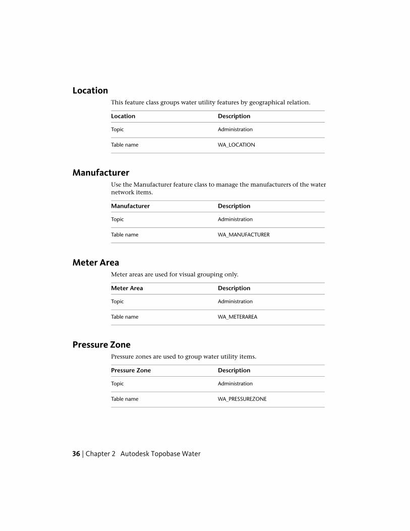
LocationThis feature class groups water utility features by geographical relation.
DescriptionLocation
AdministrationTopic
WA_LOCATIONTable name
ManufacturerUse the Manufacturer feature class to manage the manufacturers of the waternetwork items.
DescriptionManufacturer
AdministrationTopic
WA_MANUFACTURERTable name
Meter AreaMeter areas are used for visual grouping only.
DescriptionMeter Area
AdministrationTopic
WA_METERAREATable name
Pressure ZonePressure zones are used to group water utility items.
DescriptionPressure Zone
AdministrationTopic
WA_PRESSUREZONETable name
36 | Chapter 2 Autodesk Topobase Water

DescriptionPressure Zone
Workflows: Pressure Zone Creation. Formore information, see Pressure Zone Cre-ation (page 14).
Shortcut Menu
Feature Rule
Optionally, when digitizing a network feature within an existing area, thefeature is related to the pressure zone. If you digitize a network feature thatlies within several pressure zones, you are prompted to select the zone toconnect to.
This option is controlled by the feature rule SetPressureZone. You can enableor disable this feature rule in the data model administrator. See also FeatureRule: Set Pressure Zone (page 32).
To view related pipes
1 Select the pressure zone in the drawing.
2 Click Home tab ➤ Quick Access panel ➤ Attributes.
3 In the Pressure Zone form, click the Related Tables tab.
4 Click the Pipes (WA_PIPE) referencebutton.
The Pipes form is displayed showing all related pipes in the filter.
When you digitize a pressure zone while the water network features alreadyexist, the pipes are not updated and do not belong to the pressure zone. Youcan use a feature function to update the relations. See also Connect Featuresto a Zone (page 24).
See also:
■ Pressure Zone Creation (page 14)
Administration | 37
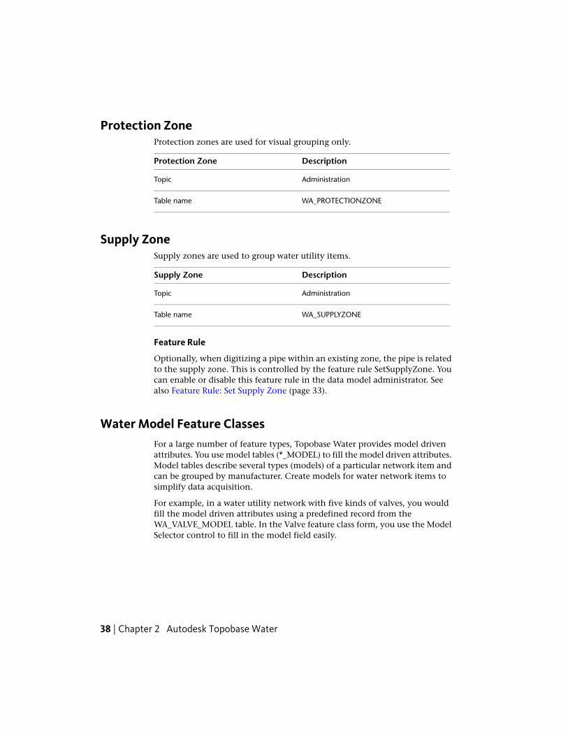
Protection ZoneProtection zones are used for visual grouping only.
DescriptionProtection Zone
AdministrationTopic
WA_PROTECTIONZONETable name
Supply ZoneSupply zones are used to group water utility items.
DescriptionSupply Zone
AdministrationTopic
WA_SUPPLYZONETable name
Feature Rule
Optionally, when digitizing a pipe within an existing zone, the pipe is relatedto the supply zone. This is controlled by the feature rule SetSupplyZone. Youcan enable or disable this feature rule in the data model administrator. Seealso Feature Rule: Set Supply Zone (page 33).
Water Model Feature ClassesFor a large number of feature types, Topobase Water provides model drivenattributes. You use model tables (*_MODEL) to fill the model driven attributes.Model tables describe several types (models) of a particular network item andcan be grouped by manufacturer. Create models for water network items tosimplify data acquisition.
For example, in a water utility network with five kinds of valves, you wouldfill the model driven attributes using a predefined record from theWA_VALVE_MODEL table. In the Valve feature class form, you use the ModelSelector control to fill in the model field easily.
38 | Chapter 2 Autodesk Topobase Water

NOTE In the Model input field, the value Choose Model indicates that you canapply a model. It does not store the model that has been applied, because at anytime you can modify the model driven attributes. The attributes are stored in themain feature class, and you use the model feature class to insert a set of attributes.You can use the model table to store reference values.
BEST PRACTICE In the feature class form, use the Model table, to search for anappropriate model. Use the model list, if you are sure which model to use. In theForm Designer, modify the model table form to hide or show model attributes,or to modify the order in the grid. Modify the main feature class form to movethe Model selector to another location.
See also Data Model: Model Tables.
Usually the model information is created either at the beginning of the projector during data acquisition.
The following table is an example of a pipe model table.
WA_PIPE_MODELTable name
Description of DIN/ISO/DVGW/TUEV value.CERTIFICATE
Date when the item was created.DATE_CREATION
Inside diameter of the pipe.DIAMETER_INSIDE
The manufacturer's designated size, ornominal diameter, such as 1" gas hydrant,2" meter, 6" pipe.
DIAMETER_NOMINAL
Outside diameter of the pipe.DIAMETER_OUTSIDE
WA_MANUFACTURERFID_MANUFACTURERManufacturer of this item.
Hydraulic friction or kind of roughness in-side the pipe; what causes a decrease inpressure relative to the pipeline length.
HYDRAULIC_FRICTION
WA_COATING_TBDID_COATING_INSIDE
WA_COATING_TBDID_COATING_OUTSIDE
Administration | 39
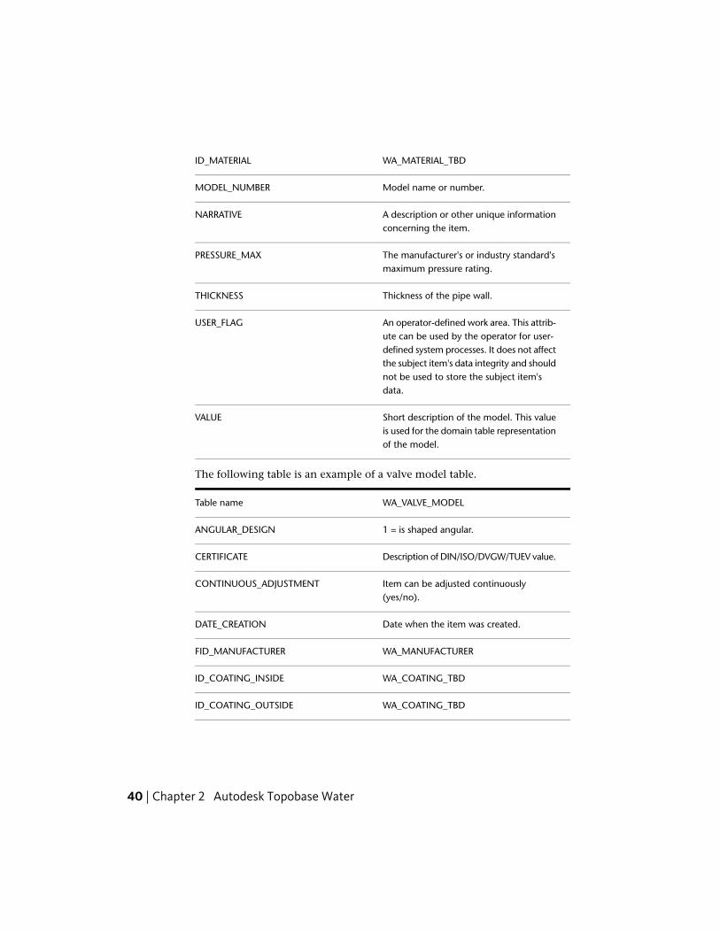
WA_MATERIAL_TBDID_MATERIAL
Model name or number.MODEL_NUMBER
A description or other unique informationconcerning the item.
NARRATIVE
The manufacturer's or industry standard'smaximum pressure rating.
PRESSURE_MAX
Thickness of the pipe wall.THICKNESS
An operator-defined work area. This attrib-ute can be used by the operator for user-
USER_FLAG
defined system processes. It does not affectthe subject item's data integrity and shouldnot be used to store the subject item'sdata.
Short description of the model. This valueis used for the domain table representationof the model.
VALUE
The following table is an example of a valve model table.
WA_VALVE_MODELTable name
1 = is shaped angular.ANGULAR_DESIGN
Description of DIN/ISO/DVGW/TUEV value.CERTIFICATE
Item can be adjusted continuously(yes/no).
CONTINUOUS_ADJUSTMENT
Date when the item was created.DATE_CREATION
WA_MANUFACTURERFID_MANUFACTURER
WA_COATING_TBDID_COATING_INSIDE
WA_COATING_TBDID_COATING_OUTSIDE
40 | Chapter 2 Autodesk Topobase Water

WA_MATERIAL_TBDID_MATERIAL
WA_VALVE_TYPE_TBDID_TYPEParticular kind, class, or group of valve,such as gate, or check.
Item is lockable (yes/no).LOCKABLE
Model name or number.MODEL_NUMBER
A description or other unique information.NARRATIVE
The manufacturer's or industry standard'smaximum pressure rating.
PRESSURE_MAX
An operator-defined work area. This attrib-ute can be used by the operator for user-
USER_FLAG
defined system processes. It does not affectthe subject item's data integrity and shouldnot be used to store the subject item'sdata.
Short description of the model. This valueis used for the domain table representationof the model.
VALUE
Length.VALVE_LENGTH
Control CableTopobase Water contains a simple data model for the maintenance of controlcables.
The data model for control cables is based on the utility model.
See also:
■ Water Topologies (page 64)
■ Cable Acquisition Workflows (page 19)
Control Cable | 41

Control CabinetA cabinet for the cable where electrical nodes are located.
DescriptionControl Cabinet
Control CableTopic
WA_C_Control_CabinetTable name
Control CableA cable used to transmit electricity or information to system controls.
DescriptionControl Cable
Control CableTopic
WA_C_CableTable name
Reverse DirectionShortcut menuSoft Split (Only Geometry)Hard Split (Also Attributes)For more information, see Split Lines (page25).Workflows: Control Cable Creation. Formore information, see Control Cable Cre-ation (page 19).
Control Cable PointA cable point that represents an electrical node.
DescriptionControl Cable Point
Control CableTopic
WA_C_Cable_PointTable name
Workflows: Control Point Creation. Formore information, see Control Point Cre-ation (page 20).
Shortcut menu
42 | Chapter 2 Autodesk Topobase Water

DescriptionControl Cable Point
Extract Points From Lines. For more inform-ation, see Extract Points from Lines (page29).
FacilityTopobase Water contains a simple data structure for facility management.Facility features are not part of the network topology. They are rather usedfor orientation or illustration purposes. The predefined feature classes comewith a number of attributes. The means by which attributes are stored in thefacility topic are dependant upon the project and purpose.
DescriptionFacility
FacilityTopic
WA_FACILITY_*Table name
The geometry feature classes store thegeometry for the graphical representation.
Geometry
They do not store attributes of the facilityfeatures, except attributes to control therepresentation, such as line type or symbol.
Workflows: Site or Facility Creation. Formore information, see Site or Facility Cre-ation (page 11).
Shortcut Menu
Facility | 43
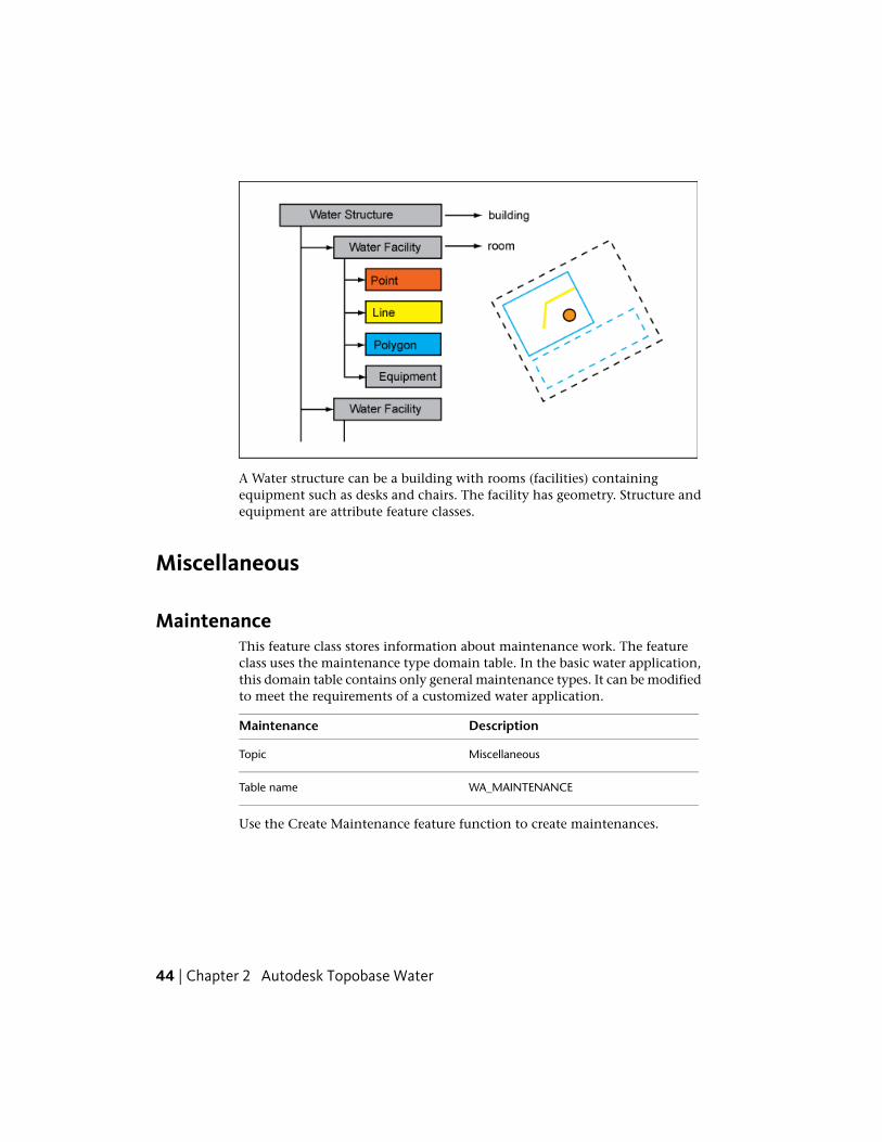
A Water structure can be a building with rooms (facilities) containingequipment such as desks and chairs. The facility has geometry. Structure andequipment are attribute feature classes.
Miscellaneous
MaintenanceThis feature class stores information about maintenance work. The featureclass uses the maintenance type domain table. In the basic water application,this domain table contains only general maintenance types. It can be modifiedto meet the requirements of a customized water application.
DescriptionMaintenance
MiscellaneousTopic
WA_MAINTENANCETable name
Use the Create Maintenance feature function to create maintenances.
44 | Chapter 2 Autodesk Topobase Water

MarkerMarkers are not part of the network topology and therefore are recorded in acommon point feature class.
DescriptionMarker
MiscellaneousTopic
WA_MARKERTable name
PipeThe basic water application contains one water line feature, pipe. Geometryis stored in the WA_LINE line string feature class. Attribute information isstored in the WA_PIPE attribute feature class.
The pipe feature class has a set of model driven attributes. Values for the modeldriven attributes are stored in the model table (suffix _MODEL). For moreinformation, see Data Model: Model Tables.
Pipe Feature Class FormUse the basic feature class form of the water pipe to view and edit featureattributes and to view related data.
The pipe feature class form contains the following elements:
■ General tab — Displays general feature information.
■ Details tab — Displays detailed feature attributes and link buttons thatprovide links to all point features the pipe is connected to.
■ Related Tables tab — Allows direct access to the following related tables:
Table Name and DescriptionRelated Table
WA_LINE – Contains line geometry.Line
WA_PIPE_TBL – Contains labels for pipefeatures.
Label
Pipe | 45

Table Name and DescriptionRelated Table
WA_MARKER – Contains marker informa-tion. The marker is placed above groundto indicate the position of a pipe feature.
Marker
WA_ANODE – Contains anode for protec-tion of the pipe.
Anode
WA_CASING – Contains casing for protec-tion of the pipe.
Casing
WA_MAINTENANCE – Contains informa-tion about pipe maintenance.
Maintenance
WA_DAMAGE – Contains recorded dam-age.
Damage
■ Table tab — Displays all controls in table form.
Some feature class forms provide functions for further processing of the selectedrecords. These functions can be accessed via menus or control buttons. Seealso Use Water Feature Functions (page 23).
PipePipes are the only standard line feature of a water utility model.
DescriptionPipe
PipeTopic
WA_PIPETable name
Contains the description of cadastral in-formation.
CADASTRAL_INFO
Elevation relative to the ground.GROUND_ELEVATION
Description of isolation type.ISOLATION
46 | Chapter 2 Autodesk Topobase Water

DescriptionPipe
Brief description where the item is located(1m of the wall).
LOCATION
Name or number of the item.NAME_NUMBER
A description or other unique informationconcerning the subject item.
NARRATIVE
Length of the pipe.PIPE_LENGTH
Operating pressure of the item.PRESSURE_OPERATING
Unique serial number of the manufacturer.SERIAL_NUMBER
Slope of the pipe measured by hand. Thisvalue is not calculated.
SLOP_MEASURED
An operator defined work area. This attrib-ute can be used by the operator for user-
USER_FLAG
defined system processes. It does not effectthe subject item's data integrity and shouldnot be used to store the subject item'sdata.
Displays the diameter, length, and materi-al. See Define Labels (page 65).
Label definition
Model driven attributes can either be filledwith the information that is stored in the
Model driven attributes
WA_PIPE_MODEL table, or you can entervalues manually.You use the Model Selector control to se-lect a set of attribute values.See also Water Model Feature Classes(page 38).
Reverse DirectionShortcut MenuSoft Split (Only Geometry)Hard Split (Also Attributes)For more information, see Split Lines (page25).
Pipe | 47

DescriptionPipe
Workflows: Network Pipe Creation. Formore information see, Network Pipe Cre-ation (page 6).Network Point With Fitting Point Creation.For more information, see Network Pipewith Fitting Point Creation (page 7).Damage Creation. For more information,see Damage Creation (page 13).Protection Creation. For more information,see Protection Creation (page 14).
Damage PointDamage points indicate locations where damage has occurred. They can berelated to a pipe. They are not part of the network topology.
DescriptionDamage Point
PipeTopic
WA_DAMAGETable name
Workflows: Damage Creation. For moreinformation, see Damage Creation (page13).
Shortcut Menu
PointThe utility points of the water data model are stored in separate attributefeature classes, one for each point type. They are grouped in the Point topic.
Geometry is stored separately from attribute data. The network point geometryis stored in the Point feature class in the Topology topic. The utility pointsare:
■ Armature
■ Emitter
■ Fitting
48 | Chapter 2 Autodesk Topobase Water

■ House Connector
■ Hydrant
■ Meter
■ Pig Launch
■ Pressure Reduction
■ Pump
■ Reservoir
■ Sample
■ Source
■ Tank
■ Valve
■ Vent
Each point feature class has a corresponding label feature class (*_TBL) withone default label definition.
Most point feature classes have an associated model table (*_MODEL). Reservoirand Source do not have model tables. Model tables can be found in theAdministration topic of the data model, under Manufacturer.
See also:
■ Water Topologies (page 64)
Point Feature Class FormUse the basic feature class forms of the Water point features to view and editfeature attributes and to view related data.
All point feature class forms contain the following elements:
■ General tab — Displays general feature information.
■ Details tab — Displays detailed feature attributes and link buttons thatprovide links to all line features (usually pipes) the points are connectedto.
Point | 49

■ Related Tables tab — Allows direct access to the following related tables:
Table Name and DescriptionRelated Table
Contains information about network maintenance.Maintenance
Contains marker information. The marker is placed aboveground to indicate the position of a network part.
Marker
Contains label text.Label
Contains point geometry.Point
■ Table tab — Displays all controls in table form.
Each point feature class form provides functions for further processing of theselected records. These functions can be accessed via menu or control buttons.See also Use Water Feature Functions (page 23).
Connect Point Features to SitesEach network point can be connected to a site. The easiest way to connect anetwork point to a site is to use the Network Point Creation workflow. Formore information, see Network Point Creation (page 5).
If you have existing points without a site connection, you can assign them toa site.
To connect a point to a site
1 Click the Document explorer icon.
2 Right-click the feature class, such as Armature, and click Show Form.
3 Select the armature to connect to the site.
4 Click the Related Tables tab.
5 Click the Point (WA_POINT) referencebutton to show the related geometry feature.
6 In the Point feature class form, click the Details tab.
50 | Chapter 2 Autodesk Topobase Water

7 Under Site, select the FID of the related site.
8 Click Update (F5).
For more information about sites, see Site (page 60).
ArmatureAn armature is an assembly that connects pipes.
DescriptionArmature
PointTopic
WA_ARMATURETable name
Workflows: Network Point Creation. Formore information, see Network Point Cre-ation (page 5).
Shortcut Menu
Extract Points From Lines. For more inform-ation, see Extract Points from Lines (page29).
EmitterAn emitter is a drip irrigation component that dispenses water to plants at aknown rate.
DescriptionEmitter
PointTopic
WA_EMITTERTable name
Workflows: Network Point Creation. Formore information, see Network Point Cre-ation (page 5).
Shortcut Menu
Extract Points From Lines. For more inform-ation, see Extract Points from Lines (page29).
Point | 51

FittingA fitting is used to connect, cap, or plug a pipe carrying water.
DescriptionFitting
PointTopic
WA_FITTINGTable name
Displays the name and number.Label definition
Workflows: Network Point Creation. Formore information, see Network Point Cre-ation (page 5).
Shortcut Menu
Extract Points From Lines. For more inform-ation, see Extract Points from Lines (page29).
House ConnectorA house connector is a service connection point on or inside a building. It isthe last point of a water network and represents the connection between thenetwork and the consumer/customer.
DescriptionHouse Connector
PointTopic
WA_HOUSE_CONNECTORTable name
Workflows: Network Point Creation. Formore information, see Network Point Cre-ation (page 5).
Shortcut Menu
House Connection Creation. For more in-formation, see House Connection Creation(page 8)Extract Points From Lines. For more inform-ation, see Extract Points from Lines (page29).
52 | Chapter 2 Autodesk Topobase Water

Manage Customer Information
The WA_HOUSE_CONNECTOR table has a Customer Number attribute.However, there is no table for managing customer information becausecustomers often use external software (for example SAP) for this.
To manage customer information within Topobase, use the data modeladministrator to create the appropriate feature classes.
To manage customer information
1 Create a new Customer feature class in the Administration topic.
2 Add attributes as needed, such as Name, Address, Telephone, and E-mail.
3 Customize the feature class form using the Form Designer.
4 In the House Connector form, add a Basic ComboBox control forCustomer Number and create the relation to the newly created tablecontaining the customers.
For more information, see the Setting Up Topobase in the TopobaseAdministrator Guide.
Generate Customer Notifications
Topobase Water helps you generate notification letters regarding plannedwork or interruptions in the water network. For example, if a pipe has a defectand the water must be stopped, you might do a network tracing to find allhouse connectors so you can notify customers.
There are several ways to generate customer notification letters.
■ Use the Topobase Report Designer.For more information about the Topobase report designer, see the ReportDesigner Introduction in the Topobase Administrator Guide.
■ Use Topobase Client to export to Microsoft® Word.
■ Export the data to any format and use external software to generate letters.For example, export a customer list to Microsoft® Excel®.
Point | 53

HydrantA hydrant is an apparatus that dispenses fluids.
DescriptionHydrant
PointTopic
WA_HYDRANTTable name
Workflows: Network Point Creation. Formore information, see Network Point Cre-ation (page 5).
Shortcut Menu
Fire Hydrant Creation. For more informa-tion, see Fire Hydrant Creation (page 9).Extract Points From Line. For more inform-ation, see Extract Points from Lines (page29).
MeterA meter is a device installed in a line for measuring the quantity and rate ofwater flowing to a facility or through a section of line.
DescriptionMeter
PointTopic
WA_METERTable name
Workflows: Network Point Creation. Formore information, see Network Point Cre-ation (page 5).
Shortcut Menu
Extract Points From Line. For more inform-ation, see Extract Points from Lines (page29).
You can use the related feature class WA_MAINTENANCE to create eventssuch as meter readings, installation, mounting, or calibration. For moreinformation, see Maintenance (page 44).
54 | Chapter 2 Autodesk Topobase Water

Pig LaunchA pig launch is a point where a pigging device is inserted to clean up a pipefitting.
DescriptionPig Launch
PointTopic
WA_PIG_LAUNCHTable name
Workflows: Network Point Creation. Formore information, see Network Point Cre-ation (page 5).
Shortcut Menu
Extract Points From Line. For more inform-ation, see Extract Points from Lines (page29).
Pressure ReductionPressure reduction is a water system component that reduces the downstreampressure of water. It is used in irrigation systems, particularly drip systems.
DescriptionPressure Reduction
PointTopic
WA_PRESSURE_REDUCTIONTable name
Workflows: Network Point Creation. Formore information, see Network Point Cre-ation (page 5).
Shortcut Menu
Extract Points From Line. For more inform-ation, see Extract Points from Lines (page29).
Point | 55

PumpA pump is a mechanical device for a water system that draws material intoitself through an entrance port and forces the material out through an exhaustport.
DescriptionPump
PointTopic
WA_PUMPTable name
Workflows: Network Point Creation. Formore information, see Network Point Cre-ation (page 5).
Shortcut Menu
Extract Points From Line. For more inform-ation, see Extract Points from Lines (page29).
ReservoirA reservoir is a body of water that supplies water to a water distribution system.
DescriptionReservoir
PointTopic
WA_RESERVOIRTable name
Workflows: Network Point Creation. Formore information, see Network Point Cre-ation (page 5).
Shortcut Menu
Extract Points From Line. For more inform-ation, see Extract Points from Lines (page29).
56 | Chapter 2 Autodesk Topobase Water

SampleThis feature class stores point locations where one or more water samples arecollected from a water utility or system.
DescriptionSample
PointTopic
WA_SAMPLETable name
Workflows: Network Point Creation. Formore information, see Network Point Cre-ation (page 5).
Shortcut Menu
Extract Points From Line. For more inform-ation, see Extract Points from Lines (page29).
SourceA source is the point from which water is supplied for processing anddistribution.
DescriptionSource
PointTopic
WA_SOURCETable name
Workflows: Network Point Creation. Formore information, see Network Point Cre-ation (page 5).
Shortcut Menu
Extract Points From Line. For more inform-ation, see Extract Points from Lines (page29).
Point | 57

TankA tank is an above or below grade receptacle or chamber used for holdingwater on a temporary basis prior to transfer or use.
DescriptionTank
PointTopic
WA_TANKTable name
Workflows: Network Point Creation. Formore information, see Network Point Cre-ation (page 5).
Shortcut Menu
Extract Points From Line. For more inform-ation, see Extract Points from Lines (page29).
ValveA valve is a fitting or device used for shutting or throttling flow through awater line.
DescriptionValve
PointTopic
WA_VALVETable name
Workflows: Network Point Creation. Formore information, see Network Point Cre-ation (page 5).
Shortcut Menu
Extract Points From Line. For more inform-ation, see Extract Points from Lines (page29).
58 | Chapter 2 Autodesk Topobase Water

VentA vent is a valve installed in a line to either release air trapped in the line,and/or allow air into a line to relieve a vacuum condition.
DescriptionVent
PointTopic
WA_VENTTable name
Workflows: Network Point Creation. Formore information, see Network Point Cre-ation (page 5).
Shortcut Menu
Extract Points From Line. For more inform-ation, see Extract Points from Lines (page29).
ProtectionUse the anode (point) and casing (polygon) feature classes to display andmanage water network protection.
Anodes and casings are usually related to a pipe. The best way to create thesefeature classes is to use the predefined Protection Creation workflow.
See also Protection Creation (page 14).
AnodeAn anode is made of a sacrificial material that is more reactive than the materialused to make a cathode (for example, a pipe). The anode is electricallyconnected to the cathode. When an electrical current is passed between theanode and the cathode, the current starts a chemical reaction where the anode,being the more reactive of the two materials, corrodes. This leaves the cathodeundamaged.
DescriptionAnode
ProtectionTopic
WA_ANODETable name
Protection | 59

DescriptionAnode
Workflows: Create an Anode. For more in-formation, see Protection Creation (page14).
Shortcut Menu
CasingA casing is a tube to protect cables and/or pipes.
DescriptionCasing
ProtectionTopic
WA_CASINGTable name
Workflows: Create Casings. For more in-formation, see Protection Creation (page14).
Shortcut Menu
SiteA site consists of one master attribute feature class with related line, point,and polygon geometry feature classes. Each network point can be connectedto a site. Sites are not part of the network topology. They are a useful meansto group various features of the water utility network to make them reachable.For example, a site stores house number and location.
DescriptionSite
SiteTopic
WA_SITE_*Table name
Site master feature class that stores the at-tributes.
WA_SITE
Site geometry feature classes. These storethe geometry for graphic presentation and
WA_SITE_LINEWA_SITE_*
normally do not contain any attributes ex-cept graphical attributes, such as line_type.
60 | Chapter 2 Autodesk Topobase Water

DescriptionSite
Workflow: Create a SiteShortcut Menu
The easiest way to connect a network point to a site is to use the NetworkPoint Creation workflow. For more information, see Network Point Creation(page 5).
With the Site or Facility Creation workflow, you can create sites that are relatedto one geometry feature. Add more geometry and equipment features usingthe feature class form. For more information, see Site or Facility Creation (page11) and Facility Creation (page 11).
See also:
■ Connect Point Features to Sites (page 50)
Understand and Work with the Water Data ModelThe Topobase water data model consists of the following components:
Feature classesWater data model component
Network geometry is stored in theWA_POINT (for nodes) and WA_LINE (for
Network geometry
edges) feature classes. These feature classesstore geometry only, not attributes. Theyare related to the water features for attrib-ute information.The rows of these tables are managed bythe Utility API. Do not enhance geometryfeature classes with customer columns.The geometry feature classes build thenetwork topology.
Network topology is stored in the _NNOD(topology nodes) and _NLNK (topologylinks) features classes.
Network topology
Only the point feature classes of the Pointtopic and the pipe feature class of the Pipetopic are part of the water network topo-logy.
Understand and Work with the Water Data Model | 61
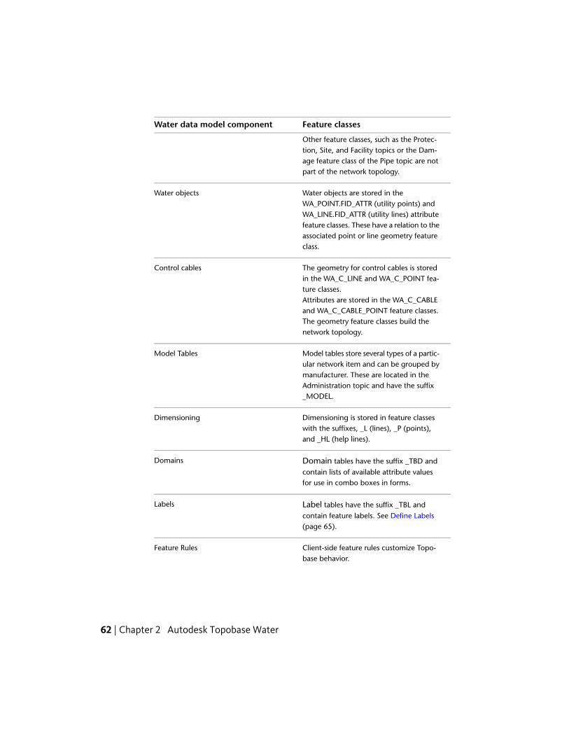
Feature classesWater data model component
Other feature classes, such as the Protec-tion, Site, and Facility topics or the Dam-age feature class of the Pipe topic are notpart of the network topology.
Water objects are stored in theWA_POINT.FID_ATTR (utility points) and
Water objects
WA_LINE.FID_ATTR (utility lines) attributefeature classes. These have a relation to theassociated point or line geometry featureclass.
The geometry for control cables is storedin the WA_C_LINE and WA_C_POINT fea-ture classes.
Control cables
Attributes are stored in the WA_C_CABLEand WA_C_CABLE_POINT feature classes.The geometry feature classes build thenetwork topology.
Model tables store several types of a partic-ular network item and can be grouped by
Model Tables
manufacturer. These are located in theAdministration topic and have the suffix_MODEL.
Dimensioning is stored in feature classeswith the suffixes, _L (lines), _P (points),and _HL (help lines).
Dimensioning
Domain tables have the suffix _TBD andcontain lists of available attribute valuesfor use in combo boxes in forms.
Domains
Label tables have the suffix _TBL andcontain feature labels. See Define Labels(page 65).
Labels
Client-side feature rules customize Topo-base behavior.
Feature Rules
62 | Chapter 2 Autodesk Topobase Water

Feature classesWater data model component
For more information, see Organization ofWater Functions and Features (page 31).
Water data model
For more information about the data model administrator, see Setting UpTopobase in the Topobase Administrator Guide.
Explore the Water Data ModelWith the data model administrator you can explore the data model with itstopics, feature classes, topologies, and utility models.
To explore the Water data model
1 Start Topobase Administrator and open the Water workspace.
2 Select the document and click Document menu ➤ Data Model.
3 Use the data model explorer to view feature classes, attributes, labeldefinitions, and topologies.
Explore the Water Data Model | 63

To view the water document structure version
1 In the data model explorer, right-click the document root node and clickDocument Info.
2 Click the Water Data Model row.
Water TopologiesThe Topobase Water data model contains the following two topologies:
■ Water network topology — Built from the node feature class WA_POINTand the edge feature class WA_LINE. A water point can be related to a site(FID_SITE).
■ Control cable topology — Built from the node feature class WA_C_POINTand the edge feature class WA_C_LINE. A cable point can be related to asite and to a control cabinet (FID_SITE, FID_CONTROL_CABINET).
The node and edge geometry feature classes are stored in the Topology topic.
Topobase Water network topology. Network points are connected with lines. Networkpoints must not lie on a network line.
64 | Chapter 2 Autodesk Topobase Water

Achieving a Valid Network Topology
The topology requires that network points always lie at the start or end of anetwork line. A network point must never lie on a line. If you insert a networkpoint on a network line, the line must be split at the insertion point. Theconsistency of the topology is maintained by feature rules.
If a network point is removed, the connecting lines must be merged.
For more information, seeSplit Lines (page 25) and Extract Points from Lines(page 29).
For more information about the feature rules, see Organization of WaterFunctions and Features (page 31).
Define LabelsThe basic Water application contains one predefined label definition for mostfeature classes. The standard attribute for the label text is called Name Number.
NOTE By default labels are not visible in the drawing. Only labels that are definedas auto labels are created during the create feature operation. Insert labels using
Home tab ➤ Quick Access panel ➤ Create Label.
Example Pipe label — The following label definition is used to display a labelcontaining the diameter, material, and length. The label text is queried fromthe tables WA_PIPE, WA_LINE, and WA_MATERIAL_TBD.
SELECT nvl2(max(pipe.DIAMETER_NOMINAL),'','')||max(pipe.DIAMET
ER_NOMINAL)||' '||round(sum(line.LENGTH),1)||' '||max(materi
al.VALUE)
FROM WA_PIPE pipe,
WA_LINE line,
WA_MATERIAL_TBD material
WHERE pipe.FID = $id
AND pipe.FID = line.FID_ATTR(+)
AND pipe.ID_MATERIAL = material.ID(+)
For more information about defining labels, see the Creating a Label Definitionin the Topobase Administrator Guide.
Define Labels | 65

66
Autodesk TopobaseWastewater
Using Wastewater WorkflowsAn important feature of Topobase Wastewater is that designers have the abilityto establish a comprehensive set of workflows. Workflows streamline businessprocesses based on the wastewater utility’s current way of doing business.Workflows help guide you through common tasks and govern the wayinformation is entered into the database. Workflows — and related businessrules that are working behind the scenes — also prevent designers from leavingout required elements, choosing incorrect materials, or including incorrectmaterial sizes, thus reducing errors during design and data updates.
Topobase Wastewater provides four types of predefined workflows:
DefinitionWorkflow Type
Create network points, pipes, house connections, firehydrants, structures, facilities, and so on.
Acquisition Workflow
Trace the network from a designated start point to anoptionally specified end point.
Analysis Workflow
Generate and print predefined or customized reports.Export reports as HTML, ASCII, or PFDF files.
Report Workflow
Classify imported wastewater content.Classification Workflow
You can also create your own workflows.
3
67

For more information about defining and managing workflows, refer toWorkflow Definitionin the Topobase Administrator Guide.
To Initiate a Wastewater workflow
Before starting a workflow, you must make sure you’ve set a display modeland generate graphics. Report workflows can be used without a drawing.
1 On the ribbon, click Home tab ➤ Display panel ➤ Display Model anddo one of the following:
■ Click the arrow button and select a previously opened display model.
■ Click Open Display Model and select a display model (.tbdm file).
■ Select Open Default Display Model.
2 Click Generate Graphic.
3 In the Topobase Task Pane, click the Workflow explorer icon to display
the workflows.
4 In the Workflows group, select a workflow and click Execute.
Optionally, you can right-click a workflow and click Execute or simplydouble-click a workflow.
You can also start workflows from the shortcut menu of the related featureclass.
Acquisition WorkflowsAcquisition workflows and rules help designers create features like manholes,network points, pipes, hydrants, house connections, and so on. Acquisitionworkflows are also used to remove features like house connections and sectionsof a wastewater network.
68 | Chapter 3 Autodesk Topobase Wastewater

Manhole CreationUse the Manhole Creation workflow to create standard and complex manholes.You can associate the manhole with a cover.
To create a manhole
1 In the Topobase Task Pane, click the Workflow explorer icon.
2 Right-click the Manhole Creation workflow. Click Execute.
3 Specify a reference record, if any.
4 In the Cover area, click one of the following options:
■ None: Specifies that no cover is associated with the manhole.
■ Digitize: Prompts you to create a cover.
■ Connect To: Prompts you to select an existing cover.
5 In the Details area, specify additional details to add to the manhole.
NOTE You can add one polygon detail to a manhole and any number of lineand point details. For more information, see Point Detail Creation (page 87).
6 Click OK.
7 Follow the prompts to create the manhole.
8 Press ESC to complete the workflow.
The manhole form is displayed so you can add attribute data.
For more information, see Cover (page 231) and Wastewater Elevation, Slope,and Height (page 335).
Network Point CreationUse the Network Point Creation workflow to create a wastewater point.
NOTE Manholes can also be created using the Manhole Creation workflow;Intermediate points can also be created automatically in the Section Creationworkflow.
Acquisition Workflows | 69
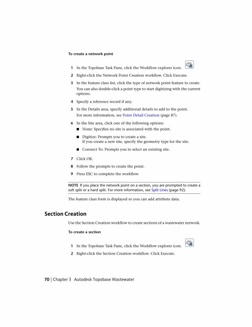
To create a network point
1 In the Topobase Task Pane, click the Workflow explorer icon.
2 Right-click the Network Point Creation workflow. Click Execute.
3 In the feature class list, click the type of network point feature to create.
You can also double-click a point type to start digitizing with the currentoptions.
4 Specify a reference record if any.
5 In the Details area, specify additional details to add to the point.
For more information, see Point Detail Creation (page 87).
6 In the Site area, click one of the following options:
■ None: Specifies no site is associated with the point.
■ Digitize: Prompts you to create a site.If you create a new site, specify the geometry type for the site.
■ Connect To: Prompts you to select an existing site.
7 Click OK.
8 Follow the prompts to create the point.
9 Press ESC to complete the workflow.
NOTE If you place the network point on a section, you are prompted to create asoft split or a hard split. For more information, see Split Lines (page 92).
The feature class form is displayed so you can add attribute data.
Section CreationUse the Section Creation workflow to create sections of a wastewater network.
To create a section
1 In the Topobase Task Pane, click the Workflow explorer icon.
2 Right-click the Section Creation workflow. Click Execute.
70 | Chapter 3 Autodesk Topobase Wastewater
3 Specify whether to create intermediate points.
4 Click OK.
5 Follow the prompts to create the section.
6 Press ESC to complete the workflow.
Digitize sections in the flow direction. Intermediate points are created at theentries of the manholes with a soft split at the section line.
NOTE You can reverse the flow direction with the Reverse Direction command.
If a vertex of the new pipe lies exactly on an existing network point feature,the pipe is soft split.
Section RemoveUse the Section Remove workflow to delete a section from the databaseincluding all related network points.
To remove a section
1 In the Topobase Task Pane, click the Workflow explorer icon.
2 Right-click the Section Remove workflow. Click Execute.
3 Specify the sections to remove.
4 Press ESC.
The workflow pane displays the selected sections and related features.
For more information, see Section (page 310).
House Connector RemoveUse the House Connector Remove workflow to remove a house connector.
To remove a house connector
1 In the Topobase Task Pane, click the Workflow explorer icon.
Acquisition Workflows | 71

2 Right-click the House Connector Remove workflow. Click Execute.
3 Specify the house connectors to remove.
4 Press ESC.
The workflow pane displays the selected house connectors and related features.
For more information, see House Connector (page 256).
Sub Drain Area CreationUse the Sub Drain Area Creation workflow to create a sub drain area. You canadd a higher level drain area.
Sections can be assigned to sub drain areas.
To create a sub drain area
1 In the Topobase Task Pane, click the Workflow explorer icon.
2 Right-click the Sub Drain Area Creation workflow. Click Execute.
72 | Chapter 3 Autodesk Topobase Wastewater

3 In the Drain Area section, click one of the following options:
■ None: Specifies no drain area is associated with the sub drain.
■ Digitize: Prompts you to create a drain.
■ Connect To: Prompts you to select an existing drain.
4 Click OK.
5 Follow the prompts to create the new sub drain area.
6 Press ESC to finish the workflow.
The feature class form is displayed so you can add attribute data.
For more information, see Drain Area (page 131).
Site CreationUse the Site Creation workflow to create a site. You can relate the site to anetwork point.
To create a site
1 In the Topobase Task Pane, click the Workflow explorer icon.
2 Right-click the Site Creation workflow. Click Execute.
3 In the Site area, specify the type of geometry to create: point, line, orpolygon.
4 Click OK.
5 Follow the prompts to create the site.
6 Press ESC to complete the workflow.
The feature class form is displayed so you can add attribute data.
Administrative Information CreationUse the Administrative Information Creation workflow to create administrationareas, washing areas with contacts, locations, and manufacturers.
Acquisition Workflows | 73

To create administrative information
1 In the Topobase Task Pane, click the Workflow explorer icon.
2 Right-click the Create Administrative Information workflow. ClickExecute.
3 Specify the feature class to create.
4 Click OK.
5 Follow the prompts.
6 Press ESC to finish the workflow.
If you create an area you can optionally relate all features contained in thisarea with the area. The relation is made if the corresponding feature rule isactivated.
For more information, see Administration (page 117).
Protection CreationUse the Create Protection workflow to add casings and/or anodes to a section.
To create a protection casing or anode
1 In the Topobase Task Pane, click the Workflow explorer icon.
2 Right-click the Create Protection workflow. Click Execute.
3 In the Choose Type Of Protection area, click Casing or Anode.
4 Click OK.
5 Follow the prompts.
6 In the Next Action area, click one of the following:
■ Open Dialog.
■ Create New Protection.
■ Create New Protection On Same Section.
7 Click OK.
74 | Chapter 3 Autodesk Topobase Wastewater
8 Press ESC to finish the workflow.
The feature class form is displayed so you can add attribute data.
For more information, see Protection (page 301).
Analysis WorkflowsAnalysis workflows and rules allow designers to trace a wastewater networkfrom one or more designated start features to an optional end feature. Networktracing begins from the start location and ends when all end features havebeen reached. You can also set attribute-dependent stop conditions, locatepoint objects on a pipe, locate point objects that are not connected to thenetwork, or pinpoint error in a network topology.
Find ConnectedTrace a wastewater network from a start feature to one or more optional endfeatures. The network is traced from the start feature to the end features, ifend features are specified.
TIP Network tracing is much more efficient when start and end features areselected. Tracing a network without selecting an end feature can take a very longtime.
To find connected features
1 In the Topobase Task Pane, click the Workflow explorer icon.
2 Right-click Find Connected.
3 Click Execute.
4 In the Workflow group, under Choose a Start Feature, do the following:
■ Click Choose.
■ Click one or more features at the start of the network trace.
■ Press ENTER to complete the selection.
5 If you do not want to trace the whole network, do the following:
■ Under Optionally Choose Stop Features, click Choose.
Analysis Workflows | 75

■ Click one or more end features.
■ Press ENTER to complete the selection.
6 Under Options, select Include Stop Features to list all connected featuresincluding the end features. If this check box is cleared, end features arenot included.
Start features are always included in the list of connected features.
7 To specify the trace direction, select Forward, Backward or Both.
8 Click OK.
9 When network tracing has finished, all connected features are displayedin a tree view in the workflow pane. Use the tools at the top of theWorkflows pane to open the feature class form, highlight selected features,and zoom to selected features.
Find Connected with Stop ConditionsThe Find Connected with Stop Condition workflow provides the samefunctionality as the Find Connected workflow with the added benefit ofdefining advanced stop features based on their attributes.
All advanced stop conditions that have been defined in the data modeladministrator are also available.
For more information about stop conditions using SQL statements, see NetworkTracer in the Topobase Administrator Guide.
To trace connected features using stop conditions
1 In the Topobase Task Pane, click the Workflow explorer icon.
2 Right-click Find Connected With Stop Conditions.
3 Click Execute.
4 In the Workflow group, under Choose a Start Feature, do the following:
■ Click Choose.
■ Click one or more features at the start of the network trace.
■ Press ENTER to complete selection.
76 | Chapter 3 Autodesk Topobase Wastewater

5 If you do not want to trace the whole network, do the following:
■ Under Optionally Choose Stop Features, click Choose.
■ Click one or more end features.
■ Press ENTER to complete selection.
6 Under Options, select Include Stop Features to list all connected featuresincluding the end features. If this check box is cleared, end features arenot included.
Start features are always included in the list of connected features.
7 To specify the trace direction, select Forward, Backward or Both.
8 Under Stop Conditions, click Add.
9 In the Stop Condition Editor dialog box, do one of the following:
■ Select an existing stop condition.
■ Click New and define a new stop condition.To learn about creating a new stop condition, see Stop ConditionEditor.
10 Click OK to save the stop condition.
11 Click OK to start network tracing.
When network tracing has finished, all connected features are displayedin a tree view in the workflow pane. Use the tools at the top of theWorkflows pane to open the feature class form, highlight selected features,and zoom to selected features.
In the Stop Condition Editor dialog box, the list displays only the stopconditions that are not assigned to any tracing template.
Find Non Split Point on SectionUse Find Non Split Point On Section to find points on a section that are notsplit.
Analysis Workflows | 77

To find non split points on a section
1 In the Topobase Task Pane, click the Workflow explorer icon.
2 Right-click Find Non Split Point on Section.
3 Click Execute.
4 Select the point feature classes to locate.
Select All to search for non split points of any feature class.
5 To perform the search on a specific set of features, click Choose and clickthe features.
6 Click OK.
The result is shown in the workflow window in an explorer view.
You can use the icons to split points, for example, select a point and clickeither Soft Split on Section, or Hard Split on Section.
78 | Chapter 3 Autodesk Topobase Wastewater

Report WorkflowsReport workflows are used to generate predefined or user-defined reports.Designers can quickly and easily generate reports from a list of predefinedreport templates. These reports include:
DescriptionPredefined report
Displays a complete list of all topics andfeatures in the wastewater database. It also
Data Model Description
shows the number of features for eachfeature class and how they are linked toother tables (according to the meta-tableTB_RELATIONS).
Displays creation dates and lengths of lines.Date Creation Statistics
Displays errors in the network.Error Statistics
Displays line and point information, listsother features, and provides a count.
Network Statistics
Displays manhole information.Manhole Statistics
Displays a wastewater section.Section
Displays section information.Section statistic
Only if the COGO extension is available.COGO reports
The report templates have been created with the Topobase Report Designer.For more information, refer to Report Designer Introduction in the TopobaseAdministrator Guide.
Report GenerationUse the Report Generation workflow to generate predefined and user-definedreports.
Report Workflows | 79

To generate reports
1 In the Topobase Task Pane, click the Workflow explorer icon.
2 Open the Report workflow, if necessary.
3 Right-click Report Generation. Click Execute.
4 In the Workflows group, select a report name and click OK.
The report is displayed in a secondary window. You can print the reportor change its format to HTML, ASCII, or PDF.
To create an Error Statistics report
1 In the Topobase Task Pane, click the Workflow explorer icon.
2 Open the Report workflow, if necessary.
3 Right-click Report Generation. Click Execute.
4 Select WW Error Statistics. Click OK.
The report is displayed in a secondary window. You can print the reportor change its format to HTML, ASCII, or PDF.
Classification WorkflowsClassification workflows are used to determine the quality of sections andmanholes based on inspection data. Damaged features are coded and quantifiedbased on a chosen wastewater standard.
Before you can use the classification workflow, you need to import inspectiondata. For more information, see Manage Inspection Data (page 96).
Classify ImportUse the Classify Import workflow to classify all sections and manholes in aselected set of imported information.
To classify imported information
1 In the Topobase Task Pane, select the intermediate document tab.
80 | Chapter 3 Autodesk Topobase Wastewater

2 Click the Workflow explorer icon.
3 Expand the Classification workflow and right-click Classify Import. ClickExecute.
4 In the Workflows group, open the list and select the import you want toclassify. Click OK.
The classification results are shown in the feature explorer.
Managing Wastewater Network TopologiesAutodesk Topobase uses topologies to model objects and phenomena of thereal world. Typically, a GIS user needs information about relationships betweenobjects with topological characteristics. Modeling of land and other flat surfacesis a perfect application for area topology. Logical topology is appropriatewherever real world objects are connected to each other in networks.
Topobase Wastewater is based on a logical topology that represents the utilitynetworks.
For more information about defining and managing workflows, refer toTopology Introduction in the Topobase Administrator Guide.
Managing Wastewater Network Topologies | 81

Check TopologiesUse the Topology Checker to locate errors in a network topology.
To check a topology for errors
1 Click the Document explorer icon.
2 Expand the Topologies listing and right-click the topology. Click TopologyChecker.
Topology errors are displayed in the Logical Topology Checker Desktopdialog box.
3 Navigate the tree view to select specific features.
4 Use the Topology Checker tools to perform the following operations onselected features:
■ Refresh the topology check after you have addressed problems.
■ Open the feature class form.
■ Highlight a feature or clear all highlighted features.
■ Zoom to a selected feature in the map.
■ Delete a selected feature.
See also:
■ Explore Wastewater Topologies (page 331)
Use Wastewater Feature FunctionsFeature functions are available in the Function menu, Classification menu,and the Network Tracer menu of the feature classes to which they apply.
82 | Chapter 3 Autodesk Topobase Wastewater

To view available functions
1 Click the Document explorer icon.
2 Under Topics, expand a feature. For example, Point.
3 Right-click a feature class. For example, Basin.
4 Click Show Form.
5 On the Basin feature class form, do one of the following:
■ Click Function menu ➤ function_name.Where function_name is the name of any function available to theselected feature.
■ Click Classification menu ➤ function_name.Where function_name is the name of any function available to theselected feature.
■ Click Network Tracer menu ➤ menufunction_name.
If you start a function from the feature class form, consider the current filter.You can apply the function to all features in the filter or to the current feature.
See also:
■ Point Feature Class Form (page 224)
■ Section Feature Class Form (page 310)
Maintenance Record CreationYou can create maintenance records for several feature classes. Use this functionto add maintenance information to a feature. Maintenance information isstored in the Maintenance feature class (WW_MAINTENANCE).
To create a maintenance record
1 Select a feature in your map. For example, a Cover.
2 Right-click the Cover feature and select Attributes.
The Cover feature class form is displayed.
3 On the Cover feature class form, do one of the following:
Use Wastewater Feature Functions | 83
4 Click Function ➤ Create Maintenance.
The Maintenance feature class form is displayed with a new record.
5 Click the Details tab and enter a maintenance date and maintenanceperiod.
The Next Maintenance Date is automatically calculated based on theentries you make for the maintenance date and maintenance period.
6 Do one of the following:
■ Click Update to accept the entries you made and keep the maintenanceform open for further changes. If no further changes are necessary,close the window.
■ Click Update & Close to accept the entries you made and close themaintenance form.
See also:
■ Maintenance (page 211)
■ Understand and Work with the Wastewater Data Model (page 111)
Marker CreationYou can create markers that are assigned to the current feature.
To create a marker
1 Select a feature in your map. For example, a Point.
2 Right-click the Point feature and select Attributes.
The Point feature class form is displayed.
3 Select the features to which you want assign a marker.
4 Click Function menu ➤ Create Marker.
5 Follow the prompts to create the marker.
The Marker feature class form is displayed with a new record.
See also:
■ Marker (page 213)
84 | Chapter 3 Autodesk Topobase Wastewater

Connect a Point to a CoverYou can assign existing covers to any network points that have a relation tothe cover feature class, for example: manhole, neutralizer, grit chamber. Usethis function. If the covers have been measured separately from the wastewaternetwork.
To connect a point to a site
1 Select a Manhole feature in your map.
2 Right-click the Manhole feature and select Attributes.
The Manhole feature class form is displayed.
3 Click Function menu ➤ Connect Point to Cover.
All points that lie inside the site detail polygon are connected.
4 Specify whether to apply the function to the current feature or to allfeatures in the filter. Click OK.
The Cover form is displayed where you can add attributes.
The resulting covers are highlighted in the drawing. If both fields arefilled, a message is displayed. Each cover can be assigned to one or twonetwork points.
When you connect an existing cover to a manhole that has a DEPTH anda BOTTOM_ELEVATION entry, the cover Z is not automatically calculated.Use the Wastewater Error Statistics report to find inconsistencies.
5 Click Update (F5).
See also:
■ Cover (page 231)
■ Report Generation (page 79)
Cover CreationFor network points, you can create a cover that is related to a network point.The cover is stored with the same coordinate as the related point.
Use this function if you have not measured the cover coordinates and wantto create them later.
Use Wastewater Feature Functions | 85

To create a cover
1 Select a feature in your map. For example, a Manhole.
2 Open the feature class form.
3 Click Function ➤ Create Cover.
4 Specify whether to apply the function to the current feature or to allfeatures in the filter. Click OK.
When you are finished, the Cover form is displayed so you can addattributes.
See also:
■ Cover (page 231)
Show Input and Output SectionsDisplay the input sections or output sections for points.
To display input or output sections
1 Select a feature in your map. For example, a Manhole.
2 Right-click the Manhole feature and select Attributes.
The Manhole feature class form is displayed.
3 In the Manhole feature class form, do one of the following:
■ Click Function menu ➤ Show Input Sections.
■ Click Function menu ➤ Show Output Sections.
The related feature class forms are displayed and the input and outputsections are highlighted in the drawing.
Show Connected SectionsYou can display the input and output sections for points.
To show connected sections
1 Select a feature in your map. For example, a Manhole.
86 | Chapter 3 Autodesk Topobase Wastewater

2 Right-click the Manhole feature and select Attributes.
The Manhole feature class form is displayed.
3 Click Function ➤ Show Connected Sections.
The related feature class forms are displayed and the sections arehighlighted in the drawing.
Point Detail CreationFor network points, you can create geometry details, for example to illustratecomplex manholes in the drawing. These are geometry feature classes thatnormally contain only attributes for representation, for example, line type.All other attribute data is stored with the master attribute feature class.
A network point can have related geometry in the drawing. Only the manhole is partof the network topology.
To create a point detail
1 Select a feature in your map. For example, a Disposal Tank.
2 Right-click the Disposal Tank feature and select Attributes.
The Disposal Tank feature class form is displayed.
Use Wastewater Feature Functions | 87

3 In the Disposal Tank feature class form, do one of the following:
■ Click Function menu ➤ Create Point Detail.
■ Click Function menu ➤ Create Line Detail.
■ Click Function menu ➤ Create Polygon Detail.
Follow the prompts to create the point, line or polygon detail.
NOTE You can create one polygon detail for each network point. You can addany number of point and line details.
See also:
■ Manhole Creation (page 69)
■ Point (page 224)
Section Height InterpolationYou can interpolate the height of a section and store these values in thenetwork point feature class.
To interpolate section height
1 Select a Section feature in your map.
2 Right-click the Section feature and select Attributes.
The Section feature class form is displayed.
3 Click Function menu ➤ Interpolate Section Height.
This function populates the BOTTOM_ELEVATION attribute for thenetwork points that lie on the section. If a BOTTOM_ELEVATION valueexists, the form is displayed so you can replace the value.
See also:
■ Section (page 310)
■ Wastewater Elevation, Slope, and Height (page 335)
88 | Chapter 3 Autodesk Topobase Wastewater
Connect Points to SiteUse this function if you have created sites separately from the wastewaternetwork and want to associate them.
To connect points to a site
1 Select a Site feature in your map.
2 Right-click the Site feature and select Attributes.
The Site feature class form is displayed.
3 Click Function menu ➤ Connect Point to Site.
All points that lie inside the site detail polygon are connected.
See also:
■ Site (page 320)
Remove Connections from a SiteYou can remove all connections that are related to a site.
To remove connections from a site
1 Select a Site feature in your map.
2 Right-click the Site feature and select Attributes.
The Site feature class form is displayed.
3 Click Function menu ➤ Remove Site.
Confirm the removal of the site and the record is removed.
See also:
■ Site (page 320)
Use Wastewater Feature Functions | 89

ClassificationClassification can also be achieved through function forms. Individualclassification can be performed on specific sections and manholes. Furthermore,manual classification is supported when done through function forms.
To classify through function forms
1 Select one or more sections or manholes of the wastewater network. Forexample, a section.
2 In the Section form, click Classification ➤ Classify.
Results are displayed in the Classification dialog box.
Network TracerUse the Network Tracer functions to specify start and stop features for networkanalysis.
To specify start and end features for network tracing
1 Select a feature in your map. For example, a Pipe.
2 Right-click the Pipe feature and select Attributes.
The Pipe form is displayed.
3 Open the Network Tracer menu do one of the following:
■ Click Set as Start Feature.
■ Click Set as End Feature.
The Network Tracer dialog box is displayed.
4 In the Network Tracer dialog box, open the Tracing Template list andselect a template.
5 Follow the on-screen instructions in the Features section. Depending onthe tracing template, there are various workflows. When you are finished,click Trace.
The resulting features are highlighted in the map and listed in the TracingResult dialog box.
90 | Chapter 3 Autodesk Topobase Wastewater

The Tracing Result dialog box displays the features in an explorer tree, fromwhich you can process the features. Expand the items, select a feature and usethe buttons on the toolbar.
To learn more about attributive network topologies, see Creating Topologiesin the Topobase Administrator Guide.
Use a Reference RecordReference records are used to create data more quickly. Define one or morereference records for each feature class. These can be used in a workflow. Youcan:
■ Use no reference record.
■ Use the last used reference record.
■ Select an available reference record.
NOTE To explore available reference records, open the related feature class formin edit mode.
To create a reference record
1 Click the Document explorer icon.
2 Expand the Point topic.
3 Right-click the feature class for the reference record you want to create.For example, House Connector.
4 Right-click and click Show Form.
5 In the form, right-click in the background and click Reference Record ➤
Add.
The New Reference Record dialog box is displayed.
6 In the Name field, enter a name, such as Digitized House Connector, andclick OK.
7 In Reference Record mode, enter the reference values to be used, such asAccuracy = Digitized.
8 Click Save.
Use a Reference Record | 91

For more information about reference records, see Using Reference Recordsin the Topobase Client User Guide.
Split LinesIf you digitize a point feature on a line or polyline feature, the line or polylineis split to preserve a correct network topology.
To digitize a point and split a line
1 Click the Document explorer icon.
2 Expand the topic for the line you want to split. For example, Pipe orSection.
3 Right-click the Pipe or Section feature class and do one of the following:
■ Click Soft Split (Only Geometry)
■ Click Hard Split (Also Attributes)
4 In the drawing, select the line representing the pipe or section.
5 In the Select dialog box, select the point feature class you want to digitize.For example, select Manhole.
6 Digitize the point.
The new point needs not to lie exactly on the selected line. If the pointlies next to the line, the line is split and the new lines move to the point.However, if the point lies on a line that is not the selected one, nosplitting is performed.
NOTE Enable Object Snap and Object Snap Tracking to ensure that the point isplaced on the line. For more information, see the AutoCAD Map Help.
92 | Chapter 3 Autodesk Topobase Wastewater

Splitting lines: When you digitize a point on a utility line or next to a utility line, thenew lines move to the point.
When a section is digitized, normally only the start and the endpointcoordinates are known, and connected using a straight line. Then, when anew point is measured, such as a house connector, this point normally doesnot lie exactly on the pipe, and the pipe must be adjusted to this new point.
Soft Split and Hard SplitBecause geometry and attributes are stored separately, one geometry featuresclass, such a point, can reference various attribute feature classes, such asmanhole, cover, fitting. For line features this allows for two different linesplitting methods: soft split and hard split.
Split Lines | 93

Wastewater data model: Relation between section and line feature class
Using a workflow you can decide whether the line is soft split or hard split,thus determining how the system handles the attribute data of the tworesulting features.
DescriptionSplit
A soft split breaks the line into two separatefeatures, each with its own geometry
Soft Split
(WW_LINE) but sharing the same attributedata (WW_SECTION).Use soft split for point features of minorimportance and when the attributes of thesection do not change.
A hard split breaks the line into two separ-ate features, each with its own geometry
Hard Split
(WW_LINE) and attribute data (WW_SEC-TION). In a hard split the attribute data isnot shared.Use hard split for point features of majorimportance or if the attributes of the sec-tion change, for example diameter, mater-ial, model.
94 | Chapter 3 Autodesk Topobase Wastewater

Wastewater data model: Soft and hard split
For more information, see Explore Wastewater Topologies (page 331).
Extract Points from LinesIf you delete a point, be sure to maintain a valid network topology. Forexample, when you delete the point you must merge the two connected lines.If more than two lines connect at the point, you cannot delete the point.
To extract a point
1 Click the Document explorer icon.
Extract Points from Lines | 95

2 Right-click the point feature class and click Extract From Line.
3 When prompted, click the feature to delete.
The point is deleted from the database and the connected lines aremerged.
Network topology: Extracting points from a network line
Manage Inspection DataIn order to avoid sanitation problems or flooding damage, a wastewaternetwork needs to be regularly inspected and, when necessary, renovated. Togauge the severity of necessary repairs and closely estimate renovation costsof damaged features, it is important to have accurate inspection data. This isdone by means of importing inspection data.
96 | Chapter 3 Autodesk Topobase Wastewater

Once you import inspection information into Topobase, you can perform anyof the following tasks:
■ Verification of wastewater inspection data.
■ Classify any damage and wastewater network features.
■ Import hydraulic computation results.
Process for Importing Inspection DataWhen you import inspection data, several processes take place before theimported content is fully integrated with your main document.
DescriptionProcess
Inspection data is imported to a temporary datacache in the form of an intermediate document. The
Import
validity of the inspection file is also checked for in-consistencies.
Feature matching occurs between the inspectiondata and GIS features of the wastewater network.
Feature Matching
If certain parameters coincide between an inspectedobject and a GIS feature (for example, section:NAME_NUMBER) a match is found. If no match isautomatically found, you can select a matchingfeature.
When a conflict between an inspection feature andits GIS feature is detected, the inspection feature is
Attribute Matching
considered a conflict feature. For example, a differ-ence in section diameters between the inspectiondata and its comparable GIS feature. Conflicts mustbe resolved before the inspection data can becommitted to the main document.
Data Validation checks the imported inspection dataagainst the specified classification model. For ex-
Data Validation
ample, section damage is checked if all necessarydata is provided and only if section main codes areused.You can flag invalid features to be ignored. Thatmeans that an invalid feature would not prevent therest of valid data from being imported.
Manage Inspection Data | 97

DescriptionProcess
During the geometry creation process, geometryfor each damage observation in the inspection datais created.
Geometry Creation
All revised data is copied from the intermediatedocument to the main document. This process alsocopies any video and photo files to the server.
Commit Data
Prepare to import inspection data
Before you can import any inspection data, you must have a wastewaterworkspace that contains two wastewater documents; the main document andan intermediate document.
The main document conatins the Wastewater Data Model module and yourwastewater project data. The intermediate document is created using theWastewater Data Model (for Intermediate Document) module, and is used totemporarily store the imported data.
To prepare a wastewater workspace for import capability
You create a wastewater import workspace that contains two documents: yourwastewater document, and the intermediate document.
1 Start Topobase Administrator.
2 In the Administrator window, click Workspace menu ➤ Create.
3 Enter a name for the workspace, such as WS_Wastewater.
4 In the Documents group of the Workspace Manager pane, add yourwastewater document. Do one of the folllowing:
■ Under Available Documents In TBSYS, select your wastewater
document, and click to add the document to the DocumentsIn Workspace <workspace name>.
■ Click New, and create a new document that contains the WastewaterData Model module.To learn more about creating a document, see To Create A Documentin the Topobase Administrator Guide.
98 | Chapter 3 Autodesk Topobase Wastewater

5 Create the intermediate document. In the Documents group of theWorkspace Manager pane, click New. Specify the following:
■ On the General tab, specify a user name for the intermediatedocument, such as WW_IMPORT.
■ On the Modules tab, select Wastewater Data Model (For IntermediateDocument).
6 Click OK.
The document is added to the wastewater import workspace.
Now you can start Topobase Client or Topobase Standalone and importinspection data.
To import inspection data using Topobase Client
To import any inspection data, you must have a wastewater workspace thatcontains two wastewater documents; the main document and the intermediatedocument.
1 Start Topobase Client.
2 In the Open Workspace dialog box, select a workspace that includes bothan intermediate document and a main wastewater document. Click Open.
3 In the Topobase Task Pane, select the intermediate document tab. Forexample, WW_IMPORT.
4 Click the Document explorer icon.
5 Right-click the intermeidate document in the tree view and select Import ➤ Wastewater Import.Optionally, you can initialize the import process by:
■ Entering TBWWIMPORT at the command line.
■ Clicking Menu Browser ➤ File ➤ Import ➤ Wastewater.
6 In the Select Import pane of the Wastewater Import dialog box, do oneof the following:
■ Click Create to create a new import.
■ Continue with an old import. Open the list of imports, if any arepresent, and select an import.
Manage Inspection Data | 99

Click Next.
7 In the Import Data - Specify Import File pane, do the following:
■ Specify the Import Type. See also Inspection File Formats (page 108).
■ Click the Add button to choose the inspection file you want to import.
TIP If there is a video file that accompanies the import file, placing them inthe same folder ensures that both will import together. Storing the files ona network server gives accessibility to all who need to import the data.
Click Next to begin importing data.
NOTE This can take awhile depending upon the size the inspection file andthe number of features involved.
8 When the file is imported, click View Log. Save the log file for furtherreference.
9 Click Next.
Features in the import file are matched against the main document.
10 In the Match Features pane, wait for the features to be matched againstthe main document and then do the following:
■ If there are feature mismatches, resolve them by excluding the featuresfrom the import, manually matching the features, or by ignoring themismatches.
■ Once all mismatched features are resolved, click Next.
11 In the Match Attributes pane, wait for the validation process to finishand then do the following:
■ For any features that fail validation, fix the problems.Conflicts can be fixed individually by selecting a feature and choosingwhether the conflicting attributes should use the old or new featurevalues. You can also fix multiple conflicts by selecting the AttributeValues Conflicting heading and choosing whether to keep the oldfeature values or replace with the new feature values.
■ Click Next.
12 In the Validate Data pane, do the following:
■ Fix all data conflicts, or ignore the errors.
100 | Chapter 3 Autodesk Topobase Wastewater

For Length Check Errors, you can specify a tolerance in the WastewaterDocument Options (page 333).
■ Click Next.
13 In the Create Geometry pane, wait for the geometry to be created. ClickNext.
14 In the Commit Import pane, click Next to begin committing theinspection data to the main document.
Click Next to copy media files and to update the main document. ClickFinish.
NOTE If you did not specify any media files, click Next to update the maindocument with imported features.
Optionally, if Jobs are enabled for the main wastewater document, the ImportSettings pane is accessible where you can do the following:
■ Select an existing job.
■ Create a new job based on a predefined job template.
To import inspection data using Topobase Client Standalone
1 Start Topobase Standalone Client.
2 Click Workspace menu ➤ Open.
3 In the Open Workspace dialog box, select a workspace that includes bothan intermediate document and a main wastewater document. Click Open.
4 Select the intermediate document tab. For example, WW_IMPORT.
5 Click the Document explorer icon.
6 Right-click the intermediate document in the tree view and select Import ➤ Wastewater Import.
Optionally, you can select Document menu ➤ Import.
7 In the Select Import pane of the Wastewater Import dialog box, do oneof the following:
■ Click Create to create a new import.
Manage Inspection Data | 101

■ Continue with an old import. Open the list of imports, if any arepresent, and select an import.
Click Next.
8 In the Import Data - Specify Import File pane, do the following:
■ Specify the Import Type. See also Inspection File Formats (page 108).
■ Click the Add button to choose the inspection file you want to import.
TIP If there is a video file that accompanies the import file, placing them inthe same folder ensures that both will import together. Storing the files ona network server gives accessibility to all who need to import the data.
Click Next to begin importing data.
NOTE This can take awhile depending upon the size the inspection file andthe number of features involved.
9 When the file is imported, click Next.
Features in the import file are matched against the main document.
10 In the Match Features pane, wait for the features to be matched againstthe main document and then do the following:
■ If there are feature mismatches, resolve them by excluding the featuresfrom the import, manually matching the features, or by ignoring themismatches.
■ Once all mismatched features are resolved, click Next.
11 In the Match Attributes pane, wait for the validation process to finishand then do the following:
■ For any features that fail validation, fix the problems.Conflicts can be fixed individually by selecting a feature and choosingwhether the conflicting attributes should use the old or new featurevalues. You can also fix multiple conflicts by selecting the AttributeValues Conflicting heading and choosing whether to keep the oldfeature values or replace with the new feature values.
■ Click Next.
12 In the Validate Data pane, do the following:
■ Fix all data conflicts, or ignore the errors.
102 | Chapter 3 Autodesk Topobase Wastewater

For Length Check Errors, you can specify a tolerance in the WastewaterDocument Options (page 333).
■ Click Next.
13 In the Create Geometry pane, wait for the geometry to be created. ClickNext.
14 In the Commit Import pane, click Next to begin committing theinspection data to the main document.
Click Next to copy media files and to update the main document. ClickFinish.
NOTE If you did not specify any media files, click Next to update the maindocument with imported features.
Optionally, if Jobs are enabled for the main wastewater document, the ImportSettings pane is accessible where you can do the following:
■ Select an existing job.
■ Create a new job based on a predefined job template.
Inspection EditorUse the Inspection Editor to review imported information pertaining to specificsections of the wastewater network.
Inspection Editor Interface
The Inspection Editor interface is divided into three panes where you canreview, edit and add observations.
■ Tools Pane — On the left side; shows the tools for managing inspectionobservations.
■ Image/Information Pane — On the right side; shows the inspection videoalong with descriptive information about the video content.
■ Inspection/Video Controls Pane — Across the bottom; controls the videoand selection of primary and secondary inspection data.
Inspection Editor | 103

Inspection Editor MenusThere are several menus included in the Inspection Editor.
Toolbar IconDescriptionMenu
Open Report—Displays an inspection re-port for the current section.The report is displayed in a secondarywindow. You can print the report orchange its format to HTML, ASCII, or PDF.
Section
Create Point Observation—Allows you tocreate an observation instance occurringat a specific point in the section.
Observation
Create Lateral Observation—Allows you tocreate an observation instance occurringsomewhere around the circumference ofthe section.
Create Longitudinal Observation—Allowsyou to create an observation instance oc-curring along the length of the section.
Auto Zoom—Automatically zooms to aselected inspection observation.
Auto Highlight—Automatically highlightsthe selected inspection observation.
Play/Pause—Starts or pauses the video.Video
Stop—Stops the video.
Fast Forward—Speeds up video.
Rewind—Rewinds the video.
Next—Advances the video by one frameso you can more accurately perform inspec-tions.
104 | Chapter 3 Autodesk Topobase Wastewater

Toolbar IconDescriptionMenu
Previous—Backs the video up by oneframe.
In/Out—An icon at the right-hand side ofthe menu that controls whether the Inspec-tion Editor is docked with the form orwhether it is undocked.
Dock (icon)
When undocked, you can still view the In-spection Editor and choose other tabs inthe form.
Tools PaneThe Tools pane is divided into four sections; Tools, Side View, Descriptionand Observation Editor.
DescriptionTool Pane Section
The Tools section contains several icons that duplicatesome of the functionality found in the Section and
Tools
Observation menus. You can choose to enable or dis-able automatic zoom and highlight, or you can opena report for inspection. At the right side of the Toolssection is an icon you can use to collapse or expandthe Tools pane.If you click the Open Report button, the inspectionreport is displayed in a secondary window. You canprint the report or change its format to HTML, ASCII,or PDF.
The Side View section displays a graphical representa-tion of an inspected section of pipe between a from
Side View
Inspection Editor | 105

DescriptionTool Pane Section
manhole and a to manhole along with their uniquefeature IDs.
NOTE The ‘from manhole’ is always at the top of theside view.
To the left of the section representation is an arrowwhich indicates flow direction. To the right of thesection representation is a list of distances and corres-ponding damage codes.Double-clicking a damage code changes the descrip-tion data shown in the Description section and alsoadvances or rewinds the video to that location alongthe section.
NOTE If multiple observations are within 2 meters ofone another, double-clicking or moving the slider overone of the observations with auto-highlight or auto-zoom all the observations. This occurs only when AutoHighlight or Auto Zoom are active.
Hovering the cursor over a damage code displays amenu where you can choose to highlight or zoom tothe damage, open a form, delete the damage observa-tion, or fix the damage observation. Navigating thered arrows in the side view to different damage obser-vations will also advance or rewind the video displayto the selected observation.
The Description section contains information regardingthe currently selected damage observation. You canfind the following information:
Description
■ Distance from the base manhole to the locationwhere the damage is reported.
■ The damage code based on the wastewaterstandard you selected.
■ The position of the damage observation based onthe Observation Editor.
■ Optionally, you can add a short description of theactual damage observation. For example, Severelengthwise crack.
106 | Chapter 3 Autodesk Topobase Wastewater

DescriptionTool Pane Section
The Observation Editor section contains a graphicalrepresentation of the inside of the inspected section
Observation Editor
looking from the ‘from manhole’ toward the ‘to man-hole’. The observation editor is further delineated bytwelve wedges representing positions on a clock.Observations in the observation editor are depicted asfollows:
■ A point on the dashed line indicates a point dam-age observation. For example, a point placed atthe 6-o-clock position means damage is localizedto that specific point in the section.
■ A solid line running around the dashed line indic-ates a lateral damage observation. For example, asolid line running along the dashed line from 7-o-clock to 10-o-clock means damage running aroundthe circumference of the section between the 7-and 10-o-clock positions.
■ A point with an arrow pointing toward or awayfrom the center indicates a longitudinal damageobservation. For example, a point at 5-o-clock withan arrow pointing toward the center means thereis damage along the length of the section startingat the 5-o-clock position and running for a spe-cified distance.
■ A dashed line running around the dashed line in-dicates a combination of a lateral and longitudinaldamage observation with a beginning at one clockposition and an end at another clock position. Forexample, a dashed line running along the dashedline from 12-o-clock to 3-o-clock means there isdamage starting at the 12-o-clock position andending some distance along the section at the 3-o-clock position.
Image/Information Pane
The Video/Information pane displays the inspection video that was importedalong with the other inspection data. Along with the video, inspection andsection data related to the video is displayed, such as a description of where
Inspection Editor | 107

the video was shot, the data the inspection team recorded the video, what thesection of pipe is made of and how big it is.
The video is synchronized with the documented observations noted in theSide View section of the Tools pane. This means that if you played the videoand notice damage 3 meter into the section, there is likely to be a damageobservation called out in the Side View.
Inspection/Video Controls Pane
The Inspection/Video Controls pane allows you to select the main andsecondary inspections with which you want to work. A main inspection isalways needed, but the secondary inspection is set to “None” by default. Youcan open the secondary inspection list and select a secondary inspection. Thesecondary inspection is displayed beside the main inspection in the side viewwhere you can perform a side-by-side comparison of the two inspections.Using a secondary inspection does not advance or rewind a video file, if oneis loaded.
The video control buttons beneath the video display duplicate the controlsin the Video menu. When using the controls while reviewing inspectionobservations, you can play, pause, stop, fast forward or rewind the video. Youcan also move frames forward or back one frame at a time to more accuratelyinspect video content.
If you only want to review video of the inspection data, you can use theInspection Editor Web. The web version displays a video window with playbackcontrols and an inspection list where you can choose the specific inspectiondata you want to view.
NOTE Topobase Client uses the Windows Media Player for video playback whichsupports WMV and MPG file formats. Topobase Web uses the Microsoft®
SilverLight™ player which only supports WMV video files.
To access the inspection editor
1 Double-click a section of the wastewater network.
2 In the Section form, click the Inspection Editor tab.
Inspection File FormatsTopobase Wastewater Import provides several Import Types to support thefollowing damage encoding rules, and classification models. The classification
108 | Chapter 3 Autodesk Topobase Wastewater

model is determined by the damage encoding rule that is used in the inspectionfile.
CommentsClassificationmodel
Damage en-coding rule
Import Type /File Format
Imports ISYBAU (*.k, *.h, *.s,*.lh, *.ey, *.lk) files contain-
ISYBAU 1996ISYBAU 1996ISYBAU 1996/2001
ing network data, and dam-age observations.ISYBAU 1996/2001 files arenot compliant with DIN EN-13508-2
NOTE Import Type ISYBAU1996/2001 supports bothISYBAU 1996, and ISYBAU2001, because the fileformat is identical.
ISYBAU 2001ISYBAU 2001
Imports ISYBAU (*.k, *.h, *.s,*.lh, *.ey, *.lk) files contain-
ATV-M 149ATV-M 143-2ATV-M 143-2
ing network data, and dam-age observations that areusing ATV-M 143-2 encod-ing.ATV-M 143-2 does notprovide a file format. Youcan use the ISYBAU1996/2001 file format toexcahange data. The ATV-M143-2 Import Type reads theISYBAU file format, and setsthe classification model toATV-M 149.
Imports ISYBAU 2006(*.XML) files.
ISYBAU 1996ISYBAU 1996ISYBAU 2006
We recommend that you useISYBAU 2006 file formats,and encoding rules thatsupport DIN EN 13508,wherever it is possible.
Inspection File Formats | 109

CommentsClassificationmodel
Damage en-coding rule
Import Type /File Format
ISYBAU 2001ISYBAU 2001
ISYBAU 2006DIN EN-13508-2
Supports DIN EN-13508-2.DWA-M 149-3DWA-M 149-2
ISYBAU 2006DIN EN-13508-2
Imports (*.XML) files contain-ing network data, and dam-age observations.
ISYBAU 2001ISYBAU 2001ATV-DVWK-M150-1
Encoding supports DIN EN-13508-2.
DWA-M 149-3DWA-M 149-2
ATV-M 149ATV-M 143-2
The file does not provide theclassification model, that
ISYBAU 2006 orDWA-M 149-3
DIN EN-13508-2
EN-13508-2
means that the default classi-fier will be applied. See alsoSet Wastewater DocumentOptions (page 333).
Damage encoding rules (supporting DIN EN 13508)
■ DWA-M 149-2: Extension of EN 13508-2 for Germany.
■ ATV-DVWK-M 150: DWA-M 149-2 for ATV.
Notice that the following supported encodings are not DIN EN 13508compliant: ISYBAU 1996, ISYBAU 2001, and ATV-M 143-2.
Classification Models
Notice that the results of ISYBAU classification models, and DWA classificationmodels can not be compared, because they use a different classification system.
110 | Chapter 3 Autodesk Topobase Wastewater

To determine the Import Type
The Import Type is based on the file format, and the damage encoding rule.
■ If you have (*.k, *.h, *.s, *.lh, *.ey, *.lk) files, you select the Import TypeISYBAU 1996/2001.
■ If the inspection uses damage encoding according to ATV-M 143-2, and ifyou have (*.k, *.h, *.s, *.lh, *.ey, *.lk) files, select the import type ATV-M143-2 (within ISYBAU 1996/2001 files).
■ If you have ISYBAU 2006 (*.XML) files, select the import type ISYBAU2006.
■ If you have ATV (*.XML) files, select the import type ISYBAU 2006.
■ if you are not sure what format your inspection file has, ask your vendorwho provided the file. Ask for the file format, and the damage encodingrule.
Understand and Work with the Wastewater DataModel
Topobase Wastewater is based on the Utility data model which stores geometryand attribute data separately. The data model contains topics, representations,domains, utilities, topologies, and intersections.
The Data Model Administrator lets you explore wastewater topics,representations, domains, utilities, topologies, and intersections in the datamodel.
DescriptionData Model Elements
Topics are containers used to organize groups offeature classes and collections of feature class tables.
Topics
A representation is a template you can use to visual-ize a feature in different locations, and store thegeometries in the database.
Representations
For more information about representations(schematics), see Data Model: Schematics in theTopobase Administrator Guide.
Domains are stored in domain tables (*_TBD) anddefine the attribute values that are used in forms.
Domains
Understand and Work with the Wastewater Data Model | 111

DescriptionData Model Elements
For more information about domains, see DataModel: Domain Tables in the Topobase Administrat-or Guide.
A utility model provides basic utility network com-ponents, which are used in the wastewater applica-tion.
Utilities
For more information about utilities, see Overviewof the Utility Model in the Topobase AdministratorGuide.
Topologies are used to model objects and phenom-ena found in the real world.
Topologies
For more information about topologies, see Topo-logy Introduction in the Topobase AdministratorGuide.
Intersections are routines used to calculate intersec-tions between two feature classes.
Intersections
For more information about intersections, see DataModel: Intersections in the Topobase AdministratorGuide.
Wastewater data model
112 | Chapter 3 Autodesk Topobase Wastewater
With the Data Model Administrator you can explore the data model with itstopics, feature classes, topologies, and utility models.
To explore the Wastewater data model
1 Start Topobase Administrator and open the Wastewater workspace.
2 Select the document and click Document menu ➤ Data Model.
3 Use the data model explorer to view feature classes, attributes, labeldefinitions, and topologies.
To view the Wastewater document structure version
1 In the data model explorer, right-click the document root node, and clickDocument Info.
2 Click the Wastewater Data Model row.
The document structure is shown in the lower information pane.
Wastewater Feature Classes and TypesThe wastewater data model is comprised of feature classes that are specific tothe design, implementation, and maintenance of wastewater networks.
Feature classes are the basic class for objects. For example, a section or manholeis a feature class. In a database, each feature class corresponds to one Oracletable. A feature class can have any number of attributes (Oracle columns), oneof which can be of type "geometry".
The WW_POINT and WW_LINE feature classes represent the points and linesthat make up the wastewater network. WW_POINT features are wastewaterfeatures such as manholes, house connectors, valves, meters and otherwastewater devices. WW_LINE features are the linestring geometries thatrepresent sections. These features carry the wastewater and control its flow.
WW_CONN is the table that stores connectivity and flow information. Westrongly recommend that you do not modify this table.
Wastewater Feature Classes and Types | 113

Feature Class TypesEach topic in the wastewater data model contains multiple types of featureclasses.
DescriptionFeature Class Type
An attribute is a feature class that has no geometry.AttributeFor more information, see Feature Class Type: Attributein the Topobase Adminstrator Guide.
The line string feature class is normally comprised ofgeometry and has one attribute that can be used forstylization by means of the Display Manager.
Line String
For more information, see Feature Class Type: Line Stringin the Topobase Adminstrator Guide.
A collection is a feature class for objects that can be eitherpoints, lines, or polygons.
Collection
For more information, see Feature Class Type: Collectionin the Topobase Adminstrator Guide.
The point feature class is made up of points that indicatethe location of feetures, such as manholes, fittings, valves,etc.
Point
For more information, see Feature Class Type: Point inthe Topobase Adminstrator Guide.
The polygon feature class is made up of line segmentsthat form a closed region. The line segments that form
Polygon
the polygon have the same line attributes. Examples ofthe polygon feature class include the Drain Area and Sub-Drain Area.For more information, see Feature Class Type: Polygonin the Topobase Adminstrator Guide.
A dimension feature class (parent attribute feature class)is related to several child feature classes that store the
Dimension
geometry components, such as points (symbols) andlines, and labels.Dimensioning is stored in feature classes with the suffixes,_L (lines), _P (points), and _HL (help lines).For more information, see Feature Class Type: Dimensionin the Topobase Adminstrator Guide.
114 | Chapter 3 Autodesk Topobase Wastewater

For a number of feature classes, Topobase Wastewater provides model drivenattributes. You use specific model tables (*_MODEL) to fill the model drivenattributes:
■ Cover, manhole, meter, valve, pump
■ Section
■ Sub drain area, marker, casing
See also the Topobase Administrator Guide, section Data Model: Model Tables.
They are used to collect several types (models) of a particular network itemand can be grouped by manufacturer.
For example, in a wastewater network with several kinds of covers, you wouldfill the model driven attributes using a predifined record from theWW_COVER_MODEL table. In the Cover feature class form, you use the ModelSelector control to fill in the model driven attributes more quickly.
NOTE In the Model input field, the value Choose Model indicates that you canapply a model. It does not store the model that has been applied, because at anytime you can modify the model driven attributes. The attributes are stored in themain feature class, and you use the model feature class to insert a set of attributes.You can use the model table to store reference values.
BEST PRACTICE In the feature class form, use the Model table, to search for anappropriate model. Use the model list, if you are sure which model to use. In theForm Designer, modify the model table form to hide or show model attributes,or to modify the order in the grid. Modify the main feature class form to movethe Model selector to another location.
The following tables show sample cover and section models.
WW_COVER_MODELTable name
-> WW_MANUFACTURERFID_MANUFACTURER
First and second dimensionDIMENSION_1 and DIMENSION_2
-> WW_COVER_AER_TBDID_AERATIONTo define the aeration type of the cover.
-> WW_COVER_SHAPE_TBDID_COVER_SHAPE
Wastewater Feature Classes and Types | 115

-> WW_COVER_LOAD_TBDID_LOAD_CLASS
-> WW_COVER_MAT_TBDID_MATERIAL
Maximum load accepted by the cover.LOAD_LIMIT
Name or number.NAME_NUMBER
A description or other unique informationconcerning the item.
NARRATIVE
An operator-defined work area. This attrib-ute can be used by the operator for user-
USER_FLAG
defined system processes. It does not effectthe subject item's data integrity and shouldnot be used to store the subject item'sdata.
AdministrationTopic
WW_SECTION_MODELTable name
Inside diameter of the pipe.DIAMETER_INSIDE
Outside diameter of the pipe.DIAMETER_OUTSIDE
First dimension.DIMENSION_1
Second dimension.DIMENSION_2
WW_MANUFACTURERFID_MANUFACTURERManufacturer of this item.
Hydraulic friction or kind of roughness in-side the pipe; what causes a decrease inpressure relative to the pipeline length.
HYDRAULIC_FRICTION
-> WW_MATERIAL_TBDID_MATERIAL
-> WW_PROFILE_TBDID_PROFILE
Model name or number.NAME_NUMBER
116 | Chapter 3 Autodesk Topobase Wastewater
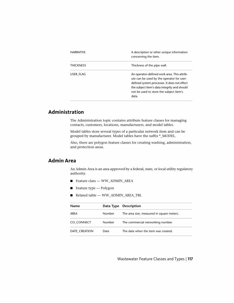
A description or other unique informationconcerning the item.
NARRATIVE
Thickness of the pipe wall.THICKNESS
An operator-defined work area. This attrib-ute can be used by the operator for user-
USER_FLAG
defined system processes. It does not effectthe subject item's data integrity and shouldnot be used to store the subject item'sdata.
AdministrationThe Administration topic contains attribute feature classes for managingcontacts, customers, locations, manufacturers, and model tables.
Model tables store several types of a particular network item and can begrouped by manufacturer. Model tables have the suffix *_MODEL.
Also, there are polygon feature classes for creating washing, administration,and protection areas.
Admin AreaAn Admin Area is an area approved by a federal, state, or local utility regulatoryauthority.
■ Feature class — WW_ADMIN_AREA
■ Feature type — Polygon
■ Related table — WW_ADMIN_AREA_TBL
DescriptionData TypeName
The area size, measured in square meters.NumberAREA
The commercial networking number.NumberCO_CONNECT
The date when the item was created.DateDATE_CREATION
Wastewater Feature Classes and Types | 117

DescriptionData TypeName
The designed wastewater treatment capacity,measured in cubic meters.
NumberDESIGN_TREAT_CAP
Feature geometry polyline. For more information,see Oracle Spatial Users Guide and Reference.
GeometryGEOM
The owner of this item.NumberID_OWNERSHIP
The name or number of this item.Varchar2NAME_NUMBER
A description or other unique information con-cerning this item.
Varchar2NARRATIVE
The population served by this area.NumberPOPULA-TION_SERVED
The residential connection number.NumberRE_CONNECT
An operator defined work area. This attribute canbe used by the operator for user defined system
Varchar2USER_FLAG
processes. It does not effect this item's data integ-rity and should not be used to store this item'sdata.
ContactThe Contact feature class manages contact information, for example; companyname, contact person, address, and email address.
The contact form provides access to several wastewater network features usingthe link buttons in the Related Tables tab.
■ Feature class — WW_CONTACT
■ Feature type — Attribute
DescriptionData TypeName
Is this contact active? (Yes/No)NumberACTIVE
The bank associated with this record.Varchar2BANK
118 | Chapter 3 Autodesk Topobase Wastewater

DescriptionData TypeName
The bank account ID associated with this record.Varchar2BANK_ACCOUNT_ID
The bank code associated with this record.Varchar2BANK_CODE
The date of birth associated with this record.DateBIRTH_DATE
The name at birth of this record.Varchar2BIRTH_NAME
The place of birth associated with this record.Varchar2BIRTH_PLACE
The city associated with this record.Varchar2CITY
The company associated with this record.Varchar2COMPANY
Additional company information for this record.Varchar2COMPANY_2
The date of the last time this record was changed.DateDATE_CHANGED
The date when this record was created.DateDATE_CREATED
The direct dialing number for this record.Varchar2DIRECT_DIALING
The email address associated with this record.Varchar2EMAIL
The fax number associated with this record.Varchar2FAX
The first name associated with this record.Varchar2FIRST_NAME
The house number associated with this record.Varchar2HOUSE
The homepage URL associated with this record.Varchar2INTERNET
The job description for this record.Varchar2JOB_DESCRIPTION
The name associated with this record.Varchar2NAME
A description or other unique information con-cerning this record.
Varchar2NARRATIVE
The ID of the person associated with this record.Varchar2PERSONAL_ID
Wastewater Feature Classes and Types | 119

DescriptionData TypeName
The mobile phone number.Varchar2PHONE_MOBILE
The office phone number.Varchar2PHONE_OFFICE
The private phone number.Varchar2PHONE_PRIVATE
The postal code associated with this record.Varchar2POSTAL_CODE
The street associated with this record.Varchar2STREET
An operator defined work area. This attribute canbe used by the operator for user defined system
Varchar2USER_FLAG
processes. It does not effect this item's data integ-rity and should not be used to store this item'sdata.
LocationThe Location feature class groups wastewater utility features by geographicalrelation.
■ Feature class — WW_LOCATION
■ Feature type — Attribute
DescriptionData TypeName
The city associated with this record.Varchar2CITY
The designation related to this record.Varchar2DESIGNATION
The district code associated with this record.NumberDISTRICTCODE
The district name associated with this record.Varchar2DISTRICTNAME
The position type ID for this record.NumberID_POSITION_TYPERelated to:
■ WW_POSITION_TYPE_TBD
120 | Chapter 3 Autodesk Topobase Wastewater

DescriptionData TypeName
Is this a flood zone? (Yes/No)NumberIS_FLOOD_AREA
The name of the location.Varchar2NAME
The name or number of the record.Varchar2NAME_NUMBER
A description or other unique information con-cerning this item.
Varchar2NARRATIVE
The postal code of this location.Varchar2POSTALCODE
The property number of this location.Varchar2PROPERTY_NUMBER
The street associated with this location.Varchar2STREET
The street code related to this location.NumberSTREETCODE
The street name related to this location.Varchar2STREETNAME
An operator defined work area. This attribute canbe used by the operator for user defined system
Varchar2USER_FLAG
processes. It does not effect this item's data integ-rity and should not be used to store this item'sdata.
The utilization of this location.Varchar2UTILIZATION
ManufacturerThe Manufacturer feature class manages the manufacturer data for all materialsand assemblies.
You can also create models for wastewater network items to simplify the dataacquisition.
■ Feature class — WW_MANUFACTURER
Wastewater Feature Classes and Types | 121

■ Feature type — Attribute
DescriptionData TypeName
The manufacturer’s company name.Varchar2COMPANY
Additional company information for this manu-facturer.
Varchar2COMPANY_2
The date when this item was created.DateDATE_CREATION
A description or other unique information con-cerning this manufacturer.
Varchar2NARRATIVE
An operator defined work area. This attribute canbe used by the operator for user defined system
Varchar2USER_FLAG
processes. It does not effect this item's data integ-rity and should not be used to store this item'sdata.
The Manfacturer feature class provides several model tables that store variousnetwork items.
Casing Model
The manufacturer’s detail information for casings.
■ Model table — WW_CASING_MODEL
■ Feature type — Attribute
■ Parent feature class — WW_MANUFACTURER
DescriptionData TypeName
A description of item's DIN/ISO/DVGW/TUEVvalue.
Varchar2CERTIFICATE
The inside diameter of the section, measured inmeters.
NumberDIAMETER_INSIDE
The manufacturer's designated size, or nominaldiameter, rounded to the nearest unit, for the
Varchar2DIAMETER_NOMIN-AL
122 | Chapter 3 Autodesk Topobase Wastewater

DescriptionData TypeName
subject item. for example, 1" gas hydrant, 2"meter, 6" pipe.
The outside diameter of the section, measuredin meters.
NumberDIAMETER_OUTSIDE
The manufacturer of this item.NumberFID_MANUFAC-TURER Related to:
■ WW_MANUFACTURER
Hydraulic friction or the roughness inside a sec-tion which decreases the pressure relative to thelength.
NumberHYDRAULIC_FRIC-TION
The type of coating used on the inside of thesection.
NumberID_COATING_INSIDE
Related to:
■ WW_COATING_TBD
The type of coating used on the outside of thesection.
NumberID_COATING_OUT-SIDE
Related to:
■ WW_COATING_TBD
The material used to manufacture this item.NumberID_MATERIAL
The model name or number of this item.Varchar2MODEL_NUMBER
The manufacturer's or industry standard's maxim-um pressure rating for this item.
Varchar2PRESSURE_MAX
The thickness of the section wall.Varchar2THICKNESS
A short description of the model. This value isused for the domain table representation of themodel.
Varchar2VALUE
Wastewater Feature Classes and Types | 123

Cover Model
The manufacturer’s detail information for covers.
■ Model table — WW_COVER_MODEL
■ Feature type — Attribute
■ Parent feature class — WW_MANUFACTURER
DescriptionData TypeName
The first dimension, measured in meters.NumberDIMENSION_1
The second dimension, measured in meters.NumberDIMENSION_2
The manufacturer of this item.NumberFID_MANUFAC-TURER Related to:
■ WW_MANUFACTURER
Defines the aeration type of the cover.NumberID_AERATIONRelated to:
■ WW_COVER_AER_TBD
The shape of the cover.NumberID_COVER_SHAPERelated to:
■ WW_COVER_SHAPE_TBD
The type of cover.NumberID_COVER_TYPERelated to:
■ WW_COVER_TYPE_TBD
The load class of the cover.NumberID_LOAD_CLASSRelated to:
■ WW_COVER_LOAD_TBD
The material used to manfacture this item.NumberID_MATERIALRelated to:
■ WW_COVER_MAT_TBD
124 | Chapter 3 Autodesk Topobase Wastewater

DescriptionData TypeName
The maximum load, measured in kilograms, ac-cepted by the cover.
NumberLOAD_LIMIT
The name or number of the model.Varchar2MODEL_NAME
Manhole Model
The manufacturer’s detail information for manholes.
■ Model table — WW_MANHOLE_MODEL
■ Feature type — Attribute
■ Parent feature class — WW_MANUFACTURER
DescriptionData TypeName
The depth of the manhole.NumberDEPTH
The first dimension, measured in meters.NumberDIMENSION_1
The second dimension, measured in meters.NumberDIMENSION_2
The manufacturer of this item.NumberFID_MANUFAC-TURER Related to:
■ WW_MANUFACTURER
The shape of the manhole.NumberID_MAN-HOLE_SHAPE Related to:
■ WW_MHOLE_SHAPE_TBD
The type of manhole.NumberID_MANHOLE_TYPERelated to:
■ WW_MHOLE_TYPE_TBD
The material used to manfacture this item.NumberID_MATERIALRelated to:
■ WW_MATERIAL_TBD
Wastewater Feature Classes and Types | 125

DescriptionData TypeName
The name or number of the model.Varchar2MODEL_NAME
Marker Model
The manufacturer’s detail information for manholes.
■ Model table — WW_MARKER_MODEL
■ Feature type — Attribute
■ Parent feature class — WW_MANUFACTURER
DescriptionData TypeName
The manufacturer of this item.NumberFID_MANUFAC-TURER Related to:
■ WW_MANUFACTURER
The material used to manfacture this item.NumberID_MATERIALRelated to:
■ WW_MATERIAL_TBD
The name or number of the model.Varchar2MODEL_NAME
The height dimension of the sign, measured inmeters.
NumberSIGN_HEIGHT
The width dimension of the sign, measured inmeters.
NumberSIGN_WIDTH
Short description of the model. This value is usedfor the domain table representation of the model.
Varchar2VALUE
Meter Model
The manufacturer’s detail information for meters.
■ Model table — WW_METER_MODEL
■ Feature type — Attribute
126 | Chapter 3 Autodesk Topobase Wastewater

■ Parent feature class — WW_MANUFACTURER
DescriptionData TypeName
The first dimension, measured in meters.NumberDIMENSION_1
The second dimension, measured in meters.NumberDIMENSION_2
The manufacturer of this item.NumberFID_MANUFAC-TURER Related to:
■ WW_MANUFACTURER
The type of meter.NumberID_METER_TYPERelated to:
■ WW_METER_TYPE_TBD
The name or number of the model.Varchar2MODEL_NAME
Pump Model
The manufacturer’s detail information for pumps.
■ Model table — WW_PUMP_MODEL
■ Feature type — Attribute
■ Parent feature class — WW_MANUFACTURER
DescriptionData TypeName
The manufacturer of this item.NumberFID_MANUFAC-TURER Related to:
■ WW_MANUFACTURER
The method used to cool this pump.NumberID_COOLING_METH-OD Related to:
■ WW_COOLING_METHOD_TBD
The type of pump.NumberID_PUMP_TYPERelated to:
Wastewater Feature Classes and Types | 127

DescriptionData TypeName
■ WW_PUMP_TYPE_TBD
The name or number of the model.Varchar2MODEL_NAME
The amount of power provided by this pump.NumberPOWER
Section Model
The manufacturer’s detail information for sections.
■ Model table — WW_SECTION_MODEL
■ Feature type — Attribute
■ Parent feature class — WW_MANUFACTURER
DescriptionData TypeName
The inside diameter of the section, measured inmeters.
NumberDIAMETER_INSIDE
The outside diameter of the section, measuredin meters.
NumberDIAMETER_OUTSIDE
The first dimension, measured in meters.NumberDIMENSION_1
The second dimension, measured in meters.NumberDIMENSION_2
The existing special profile.NumberEXIST_SPECIAL_PRO-FILE
The manufacturer of this item.NumberFID_MANUFAC-TURER Related to:
■ WW_MANUFACTURER
Hydraulic friction or the roughness inside a sec-tion which decreases the pressure relative to thelength.
NumberHYDRAULIC_FRIC-TION
The material used to manufacture this item.NumberID_MATERIAL
128 | Chapter 3 Autodesk Topobase Wastewater

DescriptionData TypeName
The profile of the section.NumberID_PROFILE
The name or number of the model.Varchar2MODEL_NAME
The thickness of the section wall.Varchar2THICKNESS
A short description of the model. This value isused for the domain table representation of themodel.
Varchar2VALUE
Valve Model
The manufacturer’s detail information for valves.
■ Model table — WW_VALVE_MODEL
■ Feature type — Attribute
■ Parent feature class — WW_MANUFACTURER
DescriptionData TypeName
The first dimension, measured in meters.NumberDIMENSION_1
The manufacturer of this item.NumberFID_MANUFAC-TURER Related to:
■ WW_MANUFACTURER
The service type for the valve.NumberID_SERVICE_TYPERelated to:
■ WW_SERVICE_TYPE_TBD
The type of valve.NumberID_VALVE_TYPERelated to:
■ WW_VALVE_TYPE_TBD
The name or number of the model.Varchar2MODEL_NAME
Wastewater Feature Classes and Types | 129

Protection AreaProtection areas are used for visual grouping only.
■ Feature class — WW_PROTECTION_AREA
■ Feature type — Polygon
■ Related table — WW_PROTECTION_AREA_TBL
DescriptionData TypeName
The area size, measured in square meters.NumberAREA
The date when the item was created.DateDATE_CREATION
Feature geometry polyline. For more information,see Oracle Spatial Users Guide and Reference.
GeometryGEOM
The name or number of this item.Varchar2NAME_NUMBER
A description or other unique information con-cerning this item.
Varchar2NARRATIVE
An operator defined work area. This attribute canbe used by the operator for user defined system
Varchar2USER_FLAG
processes. It does not effect this item's data integ-rity and should not be used to store this item'sdata.
Washing AreaDefines an area used for washing sections.
Feature rules can be enabled to allow the connection of a washing area witha section and vice-versa. See Feature Rules: Washing Area (page 330).
■ Feature class — WW_WASHING_AREA
■ Feature type — Polygon
130 | Chapter 3 Autodesk Topobase Wastewater

■ Related table — WW_WASHING_AREA_TBL
DescriptionData TypeName
The area size, measured in square meters.NumberAREA
The date when the item was created.DateDATE_CREATION
Feature geometry polyline. For more information,see Oracle Spatial Users Guide and Reference.
GeometryGEOM
The name or number of this item.Varchar2NAME_NUMBER
A description or other unique information con-cerning this item.
Varchar2NARRATIVE
An operator defined work area. This attribute canbe used by the operator for user defined system
Varchar2USER_FLAG
processes. It does not effect this item's data integ-rity and should not be used to store this item'sdata.
DimensionThe Dimension topic contains feature classes that store dimensioning in thedata base.
For more information about saving dimensioning, see Data Model:Dimensioning.
Drain AreaThe Drain Area topic contains polygon and attribute feature classes for creatingdrain and sub-drain areas in a wastewater network.
Model tables store several types of a particular network item and can begrouped by sub-drain area. Model tables have the suffix *_MODEL.
You use the Sub Drain Area Creation (page 72) workflow to digitize a drainarea.
Wastewater Feature Classes and Types | 131

Drain AreaA drain area is a region of land where water flows into a specified body ofwater, such as a river, lake, sea, ocean, or sewer pipe.
A drain area is directly connected to a section and a network point. It is usedfor flow computations such as how much wastewater flows in the section. Itsproperties are collected in a model table.
Each section can be assigned to one sub drain area.
■ Feature class — WW_DRAIN_AREA
■ Feature type — Polygon
■ Related table — WW_DRAIN_AREA_TBL
DescriptionData TypeName
The area size, measured in square meters.NumberAREA
Feature geometry polyline. For more information,see Oracle Spatial Users Guide and Reference.
GeometryGEOM
The name or number of this item.Varchar2NAME_NUMBER
A description or other unique information con-cerning this item.
Varchar2NARRATIVE
An operator defined work area. This attribute canbe used by the operator for user defined system
Varchar2USER_FLAG
processes. It does not effect this item's data integ-rity and should not be used to store this item'sdata.
Sub Drain AreaA sub-drain area is directly connected to a section and a network point. It isused for flow computations such as how much water flows in the section. Itsproperties are collected in a model table.
Each section can be assigned to one sub-drain area.
■ Feature class — WW_SUB_DRAIN_AREA
132 | Chapter 3 Autodesk Topobase Wastewater

■ Feature type — Polygon
■ Related table — WW_SUB_DRAIN_AREA_TBL
DescriptionData TypeName
The area size, measured in square meters.NumberAREA
The number of the area.NumberAREA_NUMBER
The inflow of commercial water, measured inliters / second [l/s].
NumberCOMMERCIAL_IN-FLOW
The area of the covered area, measured in squaremeters.
NumberCOVERED_AREA
The date when the item was created.DateDATE_CREATION
The discharge coefficient (psi value) of the subdrain area.
NumberDISCHARGE_COEFFI-CIENT
The amount of inflow water during dry weather,measured in liters / second [l/s].
NumberDRY_WEATHER_IN-FLOW
The factor of the covered area.NumberFACTOR_COV_AREA
The factor of the flat roof area.NumberFACTOR_FLAT_ROOF_AREA
The factor of the non-covered area.NumberFACTOR_NOT_COV_AREA
The factor of the roof area.NumberFACTOR_ROOF_AREA
The relation with the drain area.NumberFID_DRAIN_AREARelated to:
■ WW_DRAIN_AREA
The relation to the dry weather feature.NumberFID_DRY_WEATHERRelated to:
■ WW_DRY_WEATHER
The relation with one point.NumberFID_END_POINT_AT-TR Related to:
Wastewater Feature Classes and Types | 133

DescriptionData TypeName
■ WW_DISCHARGE
■ WW_DISPOSAL_TANK
■ WW_GREASE_TRAP
■ WW_GRIT_CHAMBER
■ WW_MANHOLE
■ WW_NEUTRALIZER
■ WW_OIL_WATER_SEP
■ WW_OUTFALL
■ WW_SEPTIC_TANK
The relation to the hydraulic feature.NumberFID_HYD_FEATURERelated to:
■ WW_HYD_DISCHARGE
■ WW_HYD_FREE_OUTFALL
■ WW_HYD_MANHOLE
■ WW_HYD_OUTFALL
■ WW_HYD_PUMP
■ WW_HYD_RESTR_CHAR_LINE
■ WW_HYD_RESTR_DISCHARGE
■ WW_HYD_SECTION
■ WW_HYD_STORAGE_SITE
■ WW_HYD_VALVE
The relation to a hydraulic collection.NumberFID_HYDRAUL-IC_COLLECTION Related to:
■ WW_HYDRAULIC_COLLECTION
The relation with one section.NumberFID_SECTIONRelated to:
■ WW_SECTION
The area of a flat roof, measured in square meters.NumberFLAT_ROOF_AREA
134 | Chapter 3 Autodesk Topobase Wastewater
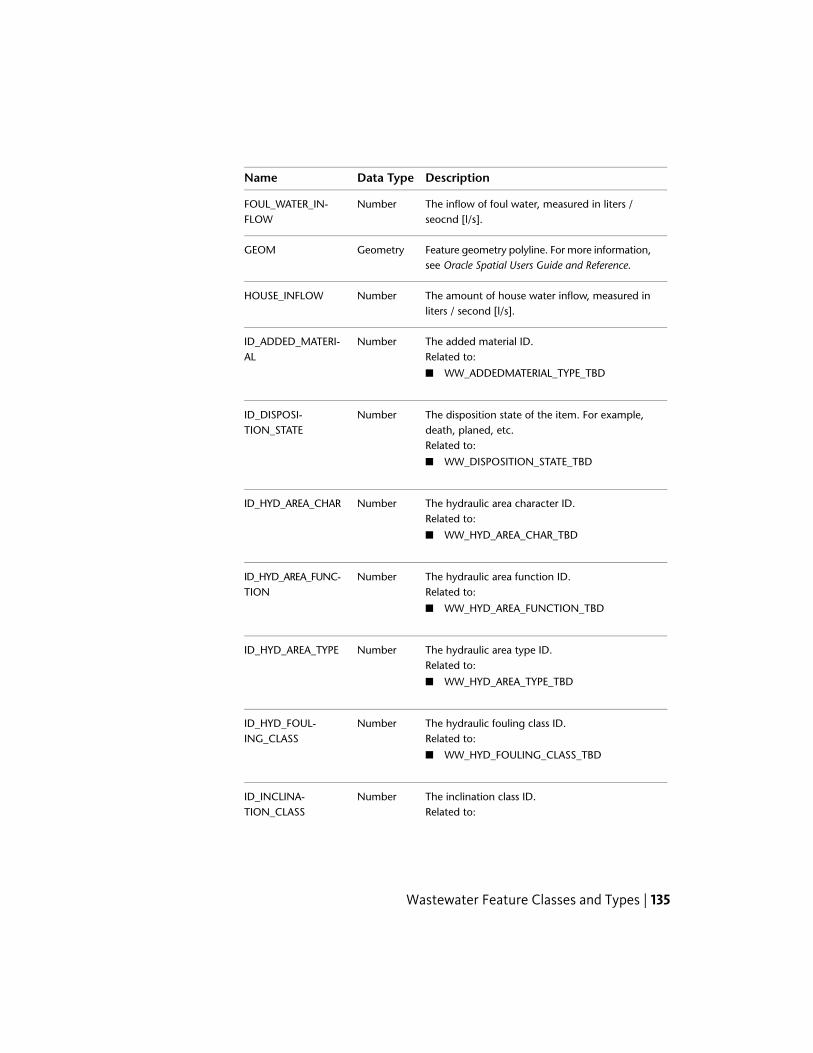
DescriptionData TypeName
The inflow of foul water, measured in liters /seocnd [l/s].
NumberFOUL_WATER_IN-FLOW
Feature geometry polyline. For more information,see Oracle Spatial Users Guide and Reference.
GeometryGEOM
The amount of house water inflow, measured inliters / second [l/s].
NumberHOUSE_INFLOW
The added material ID.NumberID_ADDED_MATERI-AL Related to:
■ WW_ADDEDMATERIAL_TYPE_TBD
The disposition state of the item. For example,death, planed, etc.
NumberID_DISPOSI-TION_STATE
Related to:
■ WW_DISPOSITION_STATE_TBD
The hydraulic area character ID.NumberID_HYD_AREA_CHARRelated to:
■ WW_HYD_AREA_CHAR_TBD
The hydraulic area function ID.NumberID_HYD_AREA_FUNC-TION Related to:
■ WW_HYD_AREA_FUNCTION_TBD
The hydraulic area type ID.NumberID_HYD_AREA_TYPERelated to:
■ WW_HYD_AREA_TYPE_TBD
The hydraulic fouling class ID.NumberID_HYD_FOUL-ING_CLASS Related to:
■ WW_HYD_FOULING_CLASS_TBD
The inclination class ID.NumberID_INCLINA-TION_CLASS Related to:
Wastewater Feature Classes and Types | 135

DescriptionData TypeName
■ WW_INCLINATION_TBD
The type of soil.NumberID_SOIL_TYPERelated to:
■ WW_SOIL_TYPE_TBD
The utilisation of the sub-drain area.NumberID_SUB_DRAIN_UTIL-ISATION Related to:
■ WW_UTILISATION_TBD
The identifier.Varchar2IDENTIFIER
The amount of industrial water inflow, measuredin liters / second [l/s].
NumberINDUSTRIAL_IN-FLOW
The amount of infiltration water inflow, measuredin liters / second [l/s].
NumberINFILTRATION_IN-FLOW
The infiltration water coefficient.NumberINFILTRATION_WA-TER_COEFFICIENT
The number of inhabitants in the sub-drain area.NumberINHABITANT
The inhabitant density, measured in inhabitants/ hectare [inhabitants/ha].
NumberINHABITANT_DENS-ITY
The name or number of this item.Varchar2NAME_NUMBER
A description or other unique information con-cerning this item.
Varchar2NARRATIVE
The area that is not covered, measured in squaremeters.
NumberNOT_COVERED_AREA
The amount of rain water inflow, measured inliters / second [l/s].
NumberRAIN_INFLOW
The area that is covered by a roof, measured insquare meters.
NumberROOF_AREA
136 | Chapter 3 Autodesk Topobase Wastewater

DescriptionData TypeName
The average slope of the sub-drain area.NumberSLOPE
The class of slope of the sub-drain area.NumberSLOPE_CLASS
The area of covered area, measured in squaremeters.
NumberSURFACE_AREA
The average usage of water per day, measuredin hours / day.
NumberUS-AGE_TIME_PER_DAY
An operator defined work area. This attribute canbe used by the operator for user defined system
Varchar2USER_FLAG
processes. It does not effect this item's data integ-rity and should not be used to store this item'sdata.
The usage of water by inhabitants measured inliters / inhabitant / day [l/inhabitant/day].
NumberWATER_USAGE
Sub Drain Area Model
In the Sub Drain Area Model feature class, the validation checks whether thesub area factors add to 1.0. FACTOR_COV_AREA + FACTOR_NOT_COV_AREA +
FACTOR_ROOF_AREA + FACTOR_FLAT_ROOF_AREA. In the feature class form,attributes that do not match are highlighted, and a tooltip explains theinconsistency.
NOTE In the wastewater document options, you can enable sub-drain area modelvalidation. See Set Wastewater Document Options (page 333).
■ Model table — WW_SUB_DRAIN_AREA_MODEL
■ Feature type — Attribute
■ Parent feature class — WW_SUB_DRAIN_AREA
DescriptionData TypeName
The discharge coefficient of the sub-drain area.This is part of the input flow which goes into thewastewater network.
NumberDISCHARGE_COEFFI-CIENT
Wastewater Feature Classes and Types | 137

DescriptionData TypeName
The covered area factor.NumberFACTOR_COV_AREA
The flat roof area factor.NumberFACTOR_FLAT_ROOF_AREA
The uncovered area factor.NumberFACTOR_NOT_COV_AREA
The roof area factor.NumberFACTOR_ROOF_AREA
The inflow of foul water, measured in liters /second [l/s].
NumberFOUL_WATER_IN-FLOW
The inflow of infiltration water, measured in liters/ second [l/s].
NumberINFILTRATION_IN-FLOW
The infiltration coefficient.NumberINFILTRATION_WA-TER_COEFFICIENT
The density of inhabitants, measured in inhabit-ants / hectares [Inhabitant/ha].
NumberINHABITANT_DENS-ITY
The name or number of the model.Varchar2MODEL_NAME
The class of slope of the sub-drain area.NumberSLOPE_CLASS
The average usage of water per day measured inhours / day.
NumberUS-AGE_TIME_PER_DAY
The usage of water by inhabitants, measured inliters / inhabitant / day [l/inhabitant/day].
NumberWATER_USAGE
See also:
■ Sub Drain Area Creation (page 72)
■ Feature Rules: Sub Drain Area (page 329)
HydraulicThe Hydraulic topic contains attribute feature classes pertaining to thehydraulic capacity of a wastewater network.
138 | Chapter 3 Autodesk Topobase Wastewater

CalculationThe Calculation feature class contain the information related to the capacityof the network and of the specific sections.
■ Feature class — WW_CALCULATION
■ Feature type — Attribute
DescriptionData TypeName
The calculation model.Varchar2CALCULA-TION_MODEL
The date when the calculation was made.DateDATE_CALCULATION
The relation to the discharger collective.NumberFID_DISCHAR-GER_COLLECTIVE Related to:
■ WW_DISCHARGER_COLLECTIVE
The relation to the hydraulic collection.NumberFID_HYDRAUL-IC_COLLECTION Related to:
■ WW_HYDRAULIC_COLLECTION
The relation to the procedure.NumberFID_PROCEDURERelated to:
■ WW_PROCEDURE
The calculation procedure.NumberID_CALCULA-TION_PROCEDURE Related to:
■ WW_CALCULATION_PROCEDURE_TBD
The general calculation procedure.NumberID_CALCULA-TION_PROCED-URE_GEN
Related to:
■ WW_CALCULATION_PROCEDURE_GEN_TBD
The frequency type.NumberID_FRE-QUENCY_TYPE Related to:
■ WW_FREQUENCY_TYPE_TBD
Wastewater Feature Classes and Types | 139

DescriptionData TypeName
The results type.NumberID_RESULTS_TYPERelated to:
■ WW_RESULTS_TYPE_TBD
The name or number of this item.Varchar2NAME_NUMBER
The name responsible for this item.Varchar2NAME_RESPONSIBLE
A description or other unique information con-cerning this item.
Varchar2NARRATIVE
The simulation days.NumberSIMULATION_DAYS
The simulation hours.NumberSIMULA-TION_HOURS
The simulation minutes.NumberSIMULA-TION_MINUTES
The simulation years.NumberSIMULATION_YEARS
Discharge Computation
The discharge computation is used to link the discharge feature with thehydraulic computation.
■ Computation table — WW_DISCHARGE_COMPUTATION
■ Feature type — Attribute
■ Parent feature class — WW_CALCULATION
DescriptionData TypeName
The discharge capacity, measured in cubicmeters.
NumberCAPACITY
The relation to calculation.NumberFID_CALCULATIONRelated to:
■ WW_CALCULATION
140 | Chapter 3 Autodesk Topobase Wastewater

DescriptionData TypeName
The relation to discharge.NumberFID_DISCHARGERelated to:
■ WW_DISCHARGE
The relation to target values.NumberFID_TARGET_VALUESRelated to:
■ WW_TARGET_VALUES
The type of hydraulic object.NumberID_HYD_OB-JECT_TYPE Related to:
■ WW_HYD_OBJECT_TYPE_TBD
The maximum overfall.NumberMAX_OVERFALL
The name or number of this item.Varchar2NAME_NUMBER
A description or other unique information con-cerning this item.
Varchar2NARRATIVE
Free Outfall Computation
The free outfall computation is used to link the free outfall feature with thehydraulic computation.
■ Computation table — WW_F_OUTFALL_COMPUTATION
■ Feature type — Attribute
■ Parent feature class — WW_CALCULATION
DescriptionData TypeName
The free outfall capacity, measured in cubicmeters.
NumberCAPACITY
The relation to calculation.NumberFID_CALCULATIONRelated to:
■ WW_CALCULATION
Wastewater Feature Classes and Types | 141

DescriptionData TypeName
The relation to the outfall.NumberFID_OUTFALLRelated to:
■ WW_OUTFALL
The relation to target values.NumberFID_TARGET_VALUESRelated to:
■ WW_TARGET_VALUES
The type of hydraulic object.NumberID_HYD_OB-JECT_TYPE Related to:
■ WW_HYD_OBJECT_TYPE_TBD
The maximum flow.NumberMAX_FLOW
The name or number of this item.Varchar2NAME_NUMBER
A description or other unique information con-cerning this item.
Varchar2NARRATIVE
The outfall frequency.NumberOUTFALL_FRE-QUENCY
Manhole Computation
The manhole computation is used to link the manhole feature with thehydraulic computation.
■ Computation table — WW_MANHOLE_COMPUTATION
■ Feature type — Attribute
■ Parent feature class — WW_CALCULATION
DescriptionData TypeName
The accumulation amount, measured in cubicmeters.
NumberACCUMULA-TION_AMOUNT
The accumulation duration.NumberACCUMULA-TION_DURATION
142 | Chapter 3 Autodesk Topobase Wastewater

DescriptionData TypeName
The accumulation frequency.NumberACCUMULA-TION_FREQUENCY
The relation to calculation.NumberFID_CALCULATIONRelated to:
■ WW_CALCULATION
The relation to the manhole feature.NumberFID_MANHOLERelated to:
■ WW_MANHOLE
The relation to target values.NumberFID_TARGET_VALUESRelated to:
■ WW_TARGET_VALUES
The type of hydraulic object.NumberID_HYD_OB-JECT_TYPE Related to:
■ WW_HYD_OBJECT_TYPE_TBD
The utility parameters ID.NumberID_UTIL_PARAMET-ERS Related to:
■ WW_UTIL_PARAMETERS_TBD
The manhole class - automatic.NumberMAN-HOLE_CLASS_AUTO
The manhole class - manual.NumberMAN-HOLE_CLASS_MANU-AL
The maximum water level.NumberMAX_WATER_LEVEL
The name or number of this item.Varchar2NAME_NUMBER
A description or other unique information con-cerning this item.
Varchar2NARRATIVE
Wastewater Feature Classes and Types | 143

DescriptionData TypeName
The overflow amount.NumberOVER-FLOW_AMOUNT
The overflow frequency.NumberOVERFLOW_FRE-QUENCY
Outfall Computation
The outfall computation is used to link the outfall feature with the hydrauliccomputation.
■ Computation table — WW_OUTFALL_COMPUTATION
■ Feature type — Attribute
■ Parent feature class — WW_CALCULATION
DescriptionData TypeName
The outfall capacity, measured in cubic meters.NumberCAPACITY
The relation to calculation.NumberFID_CALCULATIONRelated to:
■ WW_CALCULATION
The relation to the outfall feature.NumberFID_OUTFALLRelated to:
■ WW_OUTFALL
The relation to target values.NumberFID_TARGET_VALUESRelated to:
■ WW_TARGET_VALUES
The type of hydraulic object.NumberID_HYD_OB-JECT_TYPE Related to:
■ WW_HYD_OBJECT_TYPE_TBD
The maximum flow.NumberMAX_FLOW
144 | Chapter 3 Autodesk Topobase Wastewater

DescriptionData TypeName
The name or number of this item.Varchar2NAME_NUMBER
A description or other unique information con-cerning this item.
Varchar2NARRATIVE
Pump Computation
The pump computation is used to link the pump feature with the hydrauliccomputation.
■ Computation table — WW_PUMP_COMPUTATION
■ Feature type — Attribute
■ Parent feature class — WW_CALCULATION
DescriptionData TypeName
The pump capacity, measured in cubic meters.NumberCAPACITY
The dry flow.NumberDRY_FLOW
The relation to calculation.NumberFID_CALCULATIONRelated to:
■ WW_CALCULATION
The relation to the pump feature.NumberFID_PUMPRelated to:
■ WW_PUMP
The relation to target values.NumberFID_TARGET_VALUESRelated to:
■ WW_TARGET_VALUES
The type of hydraulic object.NumberID_HYD_OB-JECT_TYPE Related to:
■ WW_HYD_OBJECT_TYPE_TBD
The maximum flow.NumberMAX_FLOW
Wastewater Feature Classes and Types | 145

DescriptionData TypeName
The name or number of this item.Varchar2NAME_NUMBER
A description or other unique information con-cerning this item.
Varchar2NARRATIVE
The work duration.NumberWORK_DURATION
Section Computation
The section computation is used to link the section feature with the hydrauliccomputation.
■ Computation table — WW_SECTION_COMPUTATION
■ Feature type — Attribute
■ Parent feature class — WW_CALCULATION
DescriptionData TypeName
The complete full flow value.NumberCOM-PLETE_FULL_FLOW
The complete full speed value.NumberCOM-PLETE_FULL_SPEED
The dry weather discharge value.NumberDRYWEATHER_DIS-CHARGE
The dry weather speed value.NumberDRYWEATHER_SPEED
The dry weather input water level, measured inmeters.
NumberDW_WA-TER_LEVEL_INPUT
The dry weather output water level, measured inmeters.
NumberDW_WA-TER_LEVEL_OUTPUT
The relation to calculation.NumberFID_CALCULATIONRelated to:
■ WW_CALCULATION
146 | Chapter 3 Autodesk Topobase Wastewater

DescriptionData TypeName
The relation to the section feature.NumberFID_SECTIONRelated to:
■ WW_SECTION
The relation to target values.NumberFID_TARGET_VALUESRelated to:
■ WW_TARGET_VALUES
The type of hydraulic object.NumberID_HYD_OB-JECT_TYPE Related to:
■ WW_HYD_OBJECT_TYPE_TBD
The utility parameters ID.NumberID_UTIL_PARAMET-ERS Related to:
■ WW_UTIL_PARAMETERS_TBD
The maximum outflow.NumberMAX_OUTFLOW
The maximum speed.NumberMAX_SPEEED
The maximum input water level, measured inmeters.
NumberMAX_WA-TER_LEVEL_INPUT
The maximum output water level, measured inmeters.
NumberMAX_WA-TER_LEVEL_OUTPUT
The name or number of this item.Varchar2NAME_NUMBER
A description or other unique information con-cerning this item.
Varchar2NARRATIVE
The section class - automatic.NumberSEC-TION_CLASS_AUTO
The section class - manual.NumberSEC-TION_CLASS_MANU-AL
Wastewater Feature Classes and Types | 147

DescriptionData TypeName
The utilization degree.NumberUTILIZATION_DE-GREE
Storage Site Computation
The storage site computation is used to link the site feature with the hydrauliccomputation.
■ Computation table — WW_STOR_SITE_COMPUTATION
■ Feature type — Attribute
■ Parent feature class — WW_CALCULATION
DescriptionData TypeName
The capacity overfall value.NumberCAPACITY_OVERFALL
The days overfall value.NumberDAYS_OVERFALL
The degree of hydraulic efficiency.NumberDEGREE_HYD_EFFI-CIENCY
The duration overfall value.NumberDURATION_OVER-FALL
The duration water speed value.NumberDURATION_WA-TER_SPEED
The relation to calculation.NumberFID_CALCULATIONRelated to:
■ WW_CALCULATION
The relation to the feature.NumberFID_FEATURERelated to:
■ WW_ACC_BASIN
■ WW_BASIN
■ WW_DISCHARGE
■ WW_DISPOSAL_TANK
■ WW_EMULSION_SPLIT
148 | Chapter 3 Autodesk Topobase Wastewater

DescriptionData TypeName
■ WW_FRENCH_DRAINS
■ WW_MISC_PLANT
■ WW_OUTFALL
■ WW_PUMP
■ WW_RESTRICTOR
■ WW_SCREEN
■ WW_SITE
■ WW_STARCH
■ WW_STRAINER
■ WW_TREATMENT_PLANT
■ WW_VALVE
The relation to target values.NumberFID_TARGET_VALUESRelated to:
■ WW_TARGET_VALUES
The frequency overfall value.NumberFREQUENCY_OVER-FALL
The duration overfall value.NumberHEIGHT_STACK
The type of hydraulic object.NumberID_HYD_OB-JECT_TYPE Related to:
■ WW_HYD_OBJECT_TYPE_TBD
The hydraulic storage site ID.NumberID_HYD_STOR-AGE_SITE Related to:
■ WW_HYD_STORAGE_SITE_TBD
The maximum overfall.NumberMAX_OVERFALL
The name or number of this item.Varchar2NAME_NUMBER
A description or other unique information con-cerning this item.
Varchar2NARRATIVE
Wastewater Feature Classes and Types | 149

DescriptionData TypeName
The number overfall value.NumberNUMBER_OVERFALL
The discharge rate.NumberRATE_DISCHARGE
Valve Computation
The valve computation is used to link the valve feature with the hydrauliccomputation.
■ Computation table — WW_VALVE_COMPUTATION
■ Feature type — Attribute
■ Parent feature class — WW_CALCULATION
DescriptionData TypeName
The valve capacity, measured in cubic meters.NumberCAPACITY
The relation to calculation.NumberFID_CALCULATIONRelated to:
■ WW_CALCULATION
The relation to target values.NumberFID_TARGET_VALUESRelated to:
■ WW_TARGET_VALUES
The relation to the valve feature.NumberFID_VALVERelated to:
■ WW_VALVE
The type of hydraulic object.NumberID_HYD_OB-JECT_TYPE Related to:
■ WW_HYD_OBJECT_TYPE_TBD
The maximum flow.NumberMAX_FLOW
The name or number of this item.Varchar2NAME_NUMBER
150 | Chapter 3 Autodesk Topobase Wastewater
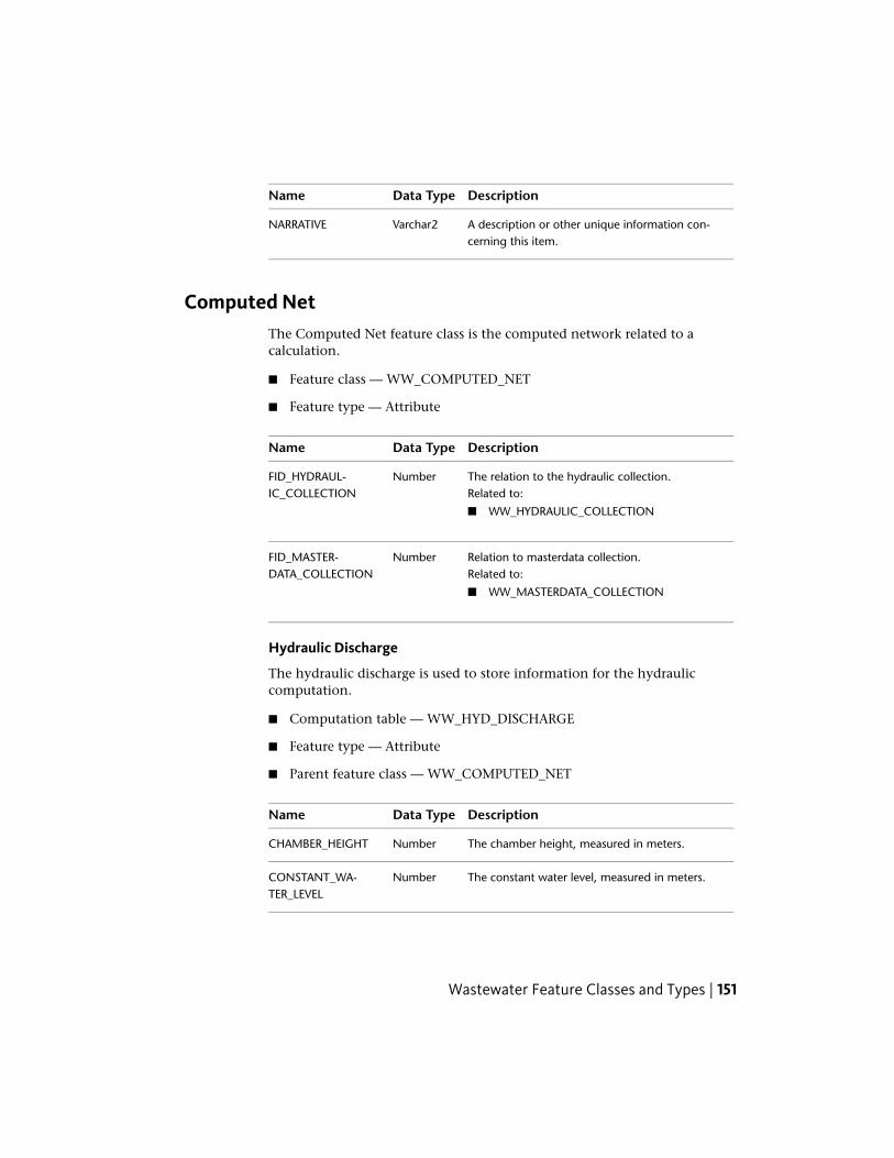
DescriptionData TypeName
A description or other unique information con-cerning this item.
Varchar2NARRATIVE
Computed NetThe Computed Net feature class is the computed network related to acalculation.
■ Feature class — WW_COMPUTED_NET
■ Feature type — Attribute
DescriptionData TypeName
The relation to the hydraulic collection.NumberFID_HYDRAUL-IC_COLLECTION Related to:
■ WW_HYDRAULIC_COLLECTION
Relation to masterdata collection.NumberFID_MASTER-DATA_COLLECTION Related to:
■ WW_MASTERDATA_COLLECTION
Hydraulic Discharge
The hydraulic discharge is used to store information for the hydrauliccomputation.
■ Computation table — WW_HYD_DISCHARGE
■ Feature type — Attribute
■ Parent feature class — WW_COMPUTED_NET
DescriptionData TypeName
The chamber height, measured in meters.NumberCHAMBER_HEIGHT
The constant water level, measured in meters.NumberCONSTANT_WA-TER_LEVEL
Wastewater Feature Classes and Types | 151

DescriptionData TypeName
The relation to the computed network.NumberFID_COM-PUTED_NET Related to:
■ WW_COMPUTED_NET
The relation to discharge.NumberFID_DISCHARGERelated to:
■ WW_DISCHARGE
The relation to the input manhole feature.NumberFID_INPUT_MAN-HOLE Related to:
■ WW_MANHOLE
The relation to the output manhole feature.NumberFID_OUTPUT_MAN-HOLE Related to:
■ WW_MANHOLE
The boundary condition ID.NumberID_BOUNDARY_CON-DITION Related to:
■ WW_BOUNDARY_CONDITION_TBD
The hydraulic discharge type ID.NumberID_HYD_DIS-CHARGE_TYPE Related to:
■ WW_HYD_DISCHARGE_TYPE_TBD
The hydraulic model ID.NumberID_HYD_MODELINGRelated to:
■ WW_HYD_MODELING_TBD
The type of hydraulic object.NumberID_HYD_OB-JECT_TYPE Related to:
■ WW_HYD_OBJECT_TYPE_TBD
The input manhole.Varchar2INPUT_MANHOLE
The name or number of this item.Varchar2NAME_NUMBER
152 | Chapter 3 Autodesk Topobase Wastewater

DescriptionData TypeName
A description or other unique information con-cerning this item.
Varchar2NARRATIVE
The output manhole.Varchar2OUTPUT_MANHOLE
The overall coefficient value.NumberOVERALL_COEFFI-CIENT
The threshold height, measured in meters.NumberTHRESHOLD_HEIGHT
The threshold length, measured in meters.NumberTHRESHOLD_LENGTH
Hydraulic Free Outfall
The hydraulic free outfall is used to store information for the hydrauliccomputation.
■ Computation table — WW_HYD_FREE_OUTFALL
■ Feature type — Attribute
■ Parent feature class — WW_COMPUTED_NET
DescriptionData TypeName
The constant water level, measured in meters.NumberCONSTANT_WA-TER_LEVEL
The relation to the computed network.NumberFID_COM-PUTED_NET Related to:
■ WW_COMPUTED_NET
The relation to the feature.NumberFID_FEATURERelated to:
■ WW_ACC_BASIN
■ WW_BASIN
■ WW_DISCHARGE
■ WW_DISPOSAL_TANK
■ WW_EMULSION_SPLIT
■ WW_FRENCH_DRAINS
Wastewater Feature Classes and Types | 153

DescriptionData TypeName
■ WW_MISC_PLANT
■ WW_OUTFALL
■ WW_PUMP
■ WW_RESTRICTOR
■ WW_SCREEN
■ WW_SITE
■ WW_STARCH
■ WW_STRAINER
■ WW_TREATMENT_PLANT
■ WW_VALVE
The boundary condition ID.NumberID_BOUNDARY_CON-DITION Related to:
■ WW_BOUNDARY_CONDITION_TBD
The hydraulic free outfall type ID.NumberID_HYD_FREE_OUT-FALL_TYPE Related to:
■ WW_HYD_FREE_OUTFALL_TYPE_TBD
The type of hydraulic object.NumberID_HYD_OB-JECT_TYPE Related to:
■ WW_HYD_OBJECT_TYPE_TBD
The name or number of this item.Varchar2NAME_NUMBER
A description or other unique information con-cerning this item.
Varchar2NARRATIVE
Hydraulic Manhole
The hydraulic manhole is used to store information for the hydrauliccomputation.
■ Computation table — WW_HYD_MANHOLE
■ Feature type — Attribute
154 | Chapter 3 Autodesk Topobase Wastewater

■ Parent feature class — WW_COMPUTED_NET
DescriptionData TypeName
The relation to the computed network.NumberFID_COM-PUTED_NET Related to:
■ WW_COMPUTED_NET
The relation to the manhole feature.NumberFID_MANHOLERelated to:
■ WW_MANHOLE
The type of hydraulic object.NumberID_HYD_OB-JECT_TYPE Related to:
■ WW_HYD_OBJECT_TYPE_TBD
Is cover pressure tight? (Yes/No)NumberIS_COVER_PRES-SURE_TIGHT
The name or number of this item.Varchar2NAME_NUMBER
A description or other unique information con-cerning this item.
Varchar2NARRATIVE
Hydraulic Outfall
The hydraulic outfall is used to store information for the hydrauliccomputation.
■ Computation table — WW_HYD_OUTFALL
■ Feature type — Attribute
■ Parent feature class — WW_COMPUTED_NET
DescriptionData TypeName
The outfall cross section surface, measured insquare meters.
NumberCROSS_SEC-TION_SURFACE
The outfall depth, measured in meters.NumberDEPTH
Wastewater Feature Classes and Types | 155

DescriptionData TypeName
The discharge coefficient value.NumberDISCHARGE_COEFFI-CIENT
The relation to the computed network.NumberFID_COM-PUTED_NET Related to:
■ WW_COMPUTED_NET
The relation to the input manhole feature.NumberFID_INPUT_MAN-HOLE Related to:
■ WW_MANHOLE
The relation with the outfall.NumberFID_OUTFALLRelated to:
■ WW_OUTFALL
The relation to the output manhole feature.NumberFID_OUTPUT_MAN-HOLE Related to:
■ WW_MANHOLE
The hydraulic modeling ID.NumberID_HYD_MODELINGRelated to:
■ WW_HYD_MODELING_TBD
The type of hydraulic object.NumberID_HYD_OB-JECT_TYPE Related to:
■ WW_HYD_OBJECT_TYPE_TBD
The hydraulic outfall type ID.NumberID_HYD_OUT-FALL_TYPE Related to:
■ WW_HYD_OUTFALL_TYPE_TBD
The input manhole.Varchar2INPUT_MANHOLE
The name or number of this item.Varchar2NAME_NUMBER
156 | Chapter 3 Autodesk Topobase Wastewater
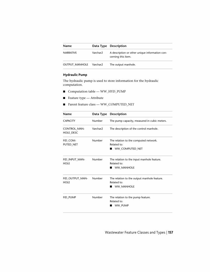
DescriptionData TypeName
A description or other unique information con-cerning this item.
Varchar2NARRATIVE
The output manhole.Varchar2OUTPUT_MANHOLE
Hydraulic Pump
The hydraulic pump is used to store information for the hydrauliccomputation.
■ Computation table — WW_HYD_PUMP
■ Feature type — Attribute
■ Parent feature class — WW_COMPUTED_NET
DescriptionData TypeName
The pump capacity, measured in cubic meters.NumberCAPACITY
The description of the control manhole.Varchar2CONTROL_MAN-HOLE_DESC
The relation to the computed network.NumberFID_COM-PUTED_NET Related to:
■ WW_COMPUTED_NET
The relation to the input manhole feature.NumberFID_INPUT_MAN-HOLE Related to:
■ WW_MANHOLE
The relation to the output manhole feature.NumberFID_OUTPUT_MAN-HOLE Related to:
■ WW_MANHOLE
The relation to the pump feature.NumberFID_PUMPRelated to:
■ WW_PUMP
Wastewater Feature Classes and Types | 157
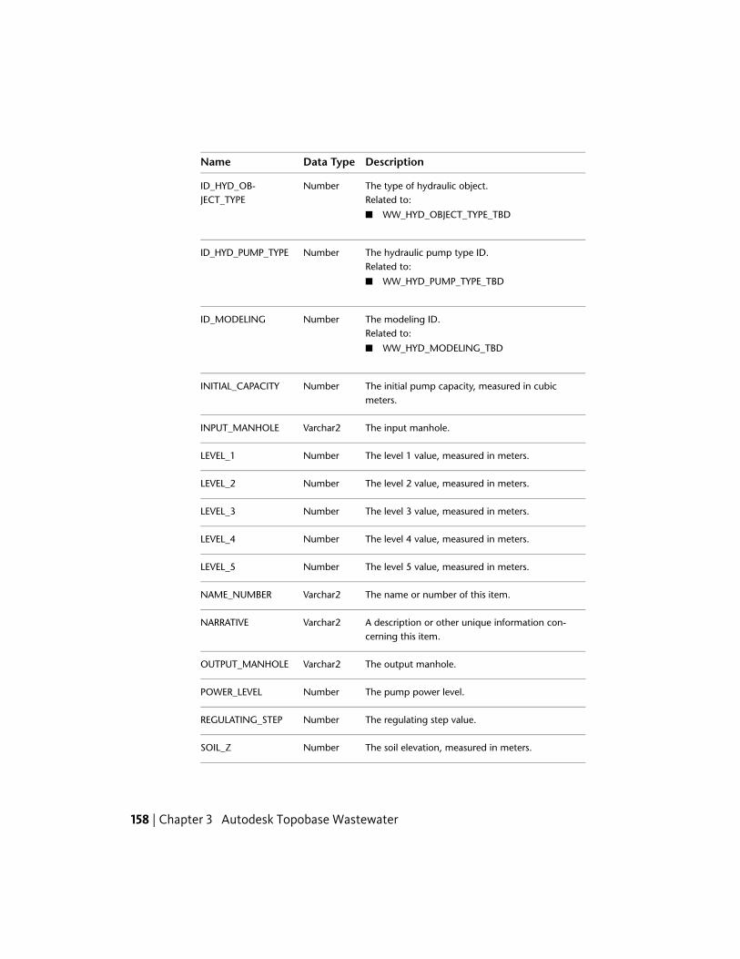
DescriptionData TypeName
The type of hydraulic object.NumberID_HYD_OB-JECT_TYPE Related to:
■ WW_HYD_OBJECT_TYPE_TBD
The hydraulic pump type ID.NumberID_HYD_PUMP_TYPERelated to:
■ WW_HYD_PUMP_TYPE_TBD
The modeling ID.NumberID_MODELINGRelated to:
■ WW_HYD_MODELING_TBD
The initial pump capacity, measured in cubicmeters.
NumberINITIAL_CAPACITY
The input manhole.Varchar2INPUT_MANHOLE
The level 1 value, measured in meters.NumberLEVEL_1
The level 2 value, measured in meters.NumberLEVEL_2
The level 3 value, measured in meters.NumberLEVEL_3
The level 4 value, measured in meters.NumberLEVEL_4
The level 5 value, measured in meters.NumberLEVEL_5
The name or number of this item.Varchar2NAME_NUMBER
A description or other unique information con-cerning this item.
Varchar2NARRATIVE
The output manhole.Varchar2OUTPUT_MANHOLE
The pump power level.NumberPOWER_LEVEL
The regulating step value.NumberREGULATING_STEP
The soil elevation, measured in meters.NumberSOIL_Z
158 | Chapter 3 Autodesk Topobase Wastewater

DescriptionData TypeName
Switchpoint1_2.NumberSWITCHPOINT1_2
Switchpoint2_1.NumberSWITCHPOINT2_1
Switchpoint2_3.NumberSWITCHPOINT2_3
Switchpoint3_2.NumberSWITCHPOINT3_2
Switchpoint3_4.NumberSWITCHPOINT3_4
Switchpoint4_3.NumberSWITCHPOINT4_3
Switchpoint4_5.NumberSWITCHPOINT4_5
Switchpoint5_4.NumberSWITCHPOINT5_4
Hydraulic Pump Line
The hydraulic pump line is used to store information for the hydrauliccomputation.
■ Computation table — WW_HYD_PUMP_LINE
■ Feature type — Attribute
■ Parent feature class — WW_HYD_PUMP
DescriptionData TypeName
The relation to hydraulic pump.NumberFID_HYD_PUMPRelated to:
■ WW_HYD_PUMP
The pump line power level.NumberPOWER_LEVEL
The regulating step value.NumberREGULATING_STEP
Wastewater Feature Classes and Types | 159

Hydraulic Restrictor Characteristic Line
The hydraulic restrictor charactistic line is used to store information for thehydraulic computation.
■ Computation table — WW_HYD_RESTR_CHAR_LINE
■ Feature type — Attribute
■ Parent feature class — WW_COMPUTED_NET
DescriptionData TypeName
The restrictor discharge value.NumberRESTRICTOR_DIS-CHARGE
The relation to hydraulic storage site.NumberFID_HYD_STOR-AGE_SITE Related to:
■ WW_HYD_STORAGE_SITE
The water level, measured in meters.NumberWATER_LEVEL
Hydraulic Restrictor Discharge
The hydraulic restrictor discharge is used to store information for the hydrauliccomputation.
■ Computation table — WW_HYD_RESTR_DISCHARGE
■ Feature type — Attribute
■ Parent feature class — WW_COMPUTED_NET
DescriptionData TypeName
The constant outflow value.NumberCONSTANT_OUT-FLOW
The relation to hydraulic storage site.NumberFID_HYD_STOR-AGE_SITE Related to:
■ WW_HYD_STORAGE_SITE
The pipe bed height, measured in meters.NumberHEIGHT_PIPE_BED
160 | Chapter 3 Autodesk Topobase Wastewater

DescriptionData TypeName
The restrictor coefficient value.NumberRESTRICTOR_COEFFI-CIENT
The restrictor diameter, measured in meters.NumberRESTRICTOR_DIA-METER
Hydraulic Section
The hydraulic section is used to store information for the hydrauliccomputation.
■ Computation table — WW_HYD_SECTION
■ Feature type — Attribute
■ Parent feature class — WW_COMPUTED_NET
DescriptionData TypeName
The calculation length, measured in meters.NumberCALCULA-TION_LENGTH
The relation to the computed network.NumberFID_COM-PUTED_NET Related to:
■ WW_COMPUTED_NET
The relation to the section feature.NumberFID_SECTIONRelated to:
■ WW_SECTION
The type of hydraulic object.NumberID_HYD_OB-JECT_TYPE Related to:
■ WW_HYD_OBJECT_TYPE_TBD
The leakage A110 ID.NumberID_LEAKAGE_A110Related to:
■ WW_LEAKAGE_A110_TBD
Wastewater Feature Classes and Types | 161

DescriptionData TypeName
The roughness method ID.NumberID_ROUGH-NESS_METHOD Related to:
■ WW_ROUGHNESS_METHOD_TBD
IS A110 Method.NumberIS_A110_METHODRelated to:
■ WW_LEAKAGE_A110_TBD
The name or number of this item.Varchar2NAME_NUMBER
A description or other unique information con-cerning this item.
Varchar2NARRATIVE
Roughness 1.NumberROUGHNESS_1
Roughness 2.NumberROUGHNESS_2
Hydraulic Storage Site
The hydraulic storage site is used to store information for the hydrauliccomputation.
■ Computation table — WW_HYD_STORAGE_SITE
■ Feature type — Attribute
■ Parent feature class — WW_COMPUTED_NET
DescriptionData TypeName
Bed KF Value.NumberBED_KF_VALUE
The storage site capacity, measured in cubicmeters.
NumberCAPACITY
The relation to the computed network.NumberFID_COM-PUTED_NET Related to:
■ WW_COMPUTED_NET
The relation to the feature.NumberFID_FEATURE
162 | Chapter 3 Autodesk Topobase Wastewater

DescriptionData TypeName
Related to:
■ WW_ACC_BASIN
■ WW_BASIN
■ WW_DISCHARGE
■ WW_DISPOSAL_TANK
■ WW_EMULSION_SPLIT
■ WW_FRENCH_DRAINS
■ WW_MISC_PLANT
■ WW_OUTFALL
■ WW_PUMP
■ WW_RESTRICTOR
■ WW_SCREEN
■ WW_SITE
■ WW_STARCH
■ WW_STRAINER
■ WW_TREATMENT_PLANT
■ WW_VALVE
The type of hydraulic object.NumberID_HYD_OB-JECT_TYPE Related to:
■ WW_HYD_OBJECT_TYPE_TBD
The hydraulic storage site ID.NumberID_HYD_STOR-AGE_SITE Related to:
■ WW_HYD_STORAGE_SITE_TBD
The infiltration surface, measured in squaremeters.
NumberINF_SURFACE
The infiltration water level, measured in meters.NumberINF_WATER_LEVEL
The initial pump capacity, measured in cubicmeters.
NumberINITIAL_CAPACITY
Wastewater Feature Classes and Types | 163

DescriptionData TypeName
IS Restrictor Discharge.NumberIS_RESTRICTOR_DIS-CHARGE
IS Restrictor Line.NumberIS_RESTRICTOR_LINE
The name or number of this item.Varchar2NAME_NUMBER
A description or other unique information con-cerning this item.
Varchar2NARRATIVE
The slope KF value.NumberSLOPE_KF_VALUE
The water level, measured in meters.NumberWATER_LEVEL
Hydraulic Capacity Line
The hydraulic capacity line is used to store information for the hydrauliccomputation.
■ Computation table — WW_HYD_CAPACITY_LINE
■ Feature type — Attribute
■ Parent feature class — WW_HYD_STORAGE_SITE
DescriptionData TypeName
The capacity, measured in cubic meters.NumberCAPACITY
The relation to storage site.NumberFID_HYD_STOR-AGE_SITE Related to:
■ WW_HYD_STORAGE_SITE
The capacity line water level, measured in meters.NumberWATER_LEVEL
Hydraulic Infiltration Line
The hydraulic infiltration line is used to store information for the hydrauliccomputation.
■ Computation table — WW_HYD_INFILTRATION_LINE
164 | Chapter 3 Autodesk Topobase Wastewater
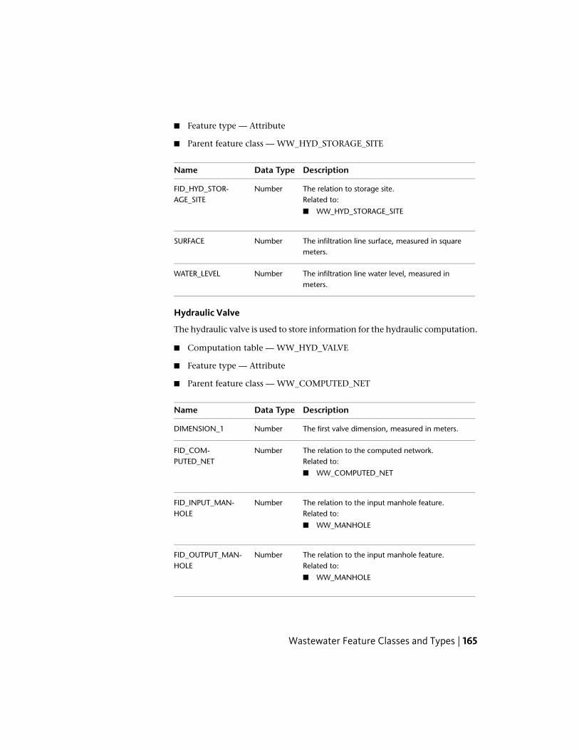
■ Feature type — Attribute
■ Parent feature class — WW_HYD_STORAGE_SITE
DescriptionData TypeName
The relation to storage site.NumberFID_HYD_STOR-AGE_SITE Related to:
■ WW_HYD_STORAGE_SITE
The infiltration line surface, measured in squaremeters.
NumberSURFACE
The infiltration line water level, measured inmeters.
NumberWATER_LEVEL
Hydraulic Valve
The hydraulic valve is used to store information for the hydraulic computation.
■ Computation table — WW_HYD_VALVE
■ Feature type — Attribute
■ Parent feature class — WW_COMPUTED_NET
DescriptionData TypeName
The first valve dimension, measured in meters.NumberDIMENSION_1
The relation to the computed network.NumberFID_COM-PUTED_NET Related to:
■ WW_COMPUTED_NET
The relation to the input manhole feature.NumberFID_INPUT_MAN-HOLE Related to:
■ WW_MANHOLE
The relation to the input manhole feature.NumberFID_OUTPUT_MAN-HOLE Related to:
■ WW_MANHOLE
Wastewater Feature Classes and Types | 165

DescriptionData TypeName
The relation to the valve feature.NumberFID_VALVERelated to:
■ WW_VALVE
The hydraulic modeling ID.NumberID_HYD_MODELINGRelated to:
■ WW_HYD_MODELING_TBD
The type of hydraulic object.NumberID_HYD_OB-JECT_TYPE Related to:
■ WW_HYD_OBJECT_TYPE_TBD
The hydraulic valve type ID.NumberID_HYD_VALVE_TYPERelated to:
■ WW_HYD_VALVE_TYPE_TBD
The input manhole.Varchar2INPUT_MANHOLE
The leakage coefficient value.NumberLEAKAGE_COEFFI-CIENT
The maximum stroke height value.NumberMAX_STROKE_HEIGHT
The name or number of this item.Varchar2NAME_NUMBER
A description or other unique information con-cerning this item.
Varchar2NARRATIVE
The output manhole.Varchar2OUTPUT_MANHOLE
The start valve value.NumberSTART_VALVE
The start valve speed value.NumberSTART_VALVE_SPEED
The zero position of the valve.NumberZERO_POSITION
166 | Chapter 3 Autodesk Topobase Wastewater

LoadThe Load feature class contains the rain quantities used for the calculation.
■ Feature class — WW_LOAD
■ Feature type — Attribute
DescriptionData TypeName
The relation to hydraulic collection.NumberFID_HYDRAUL-IC_COLLECTION Related to:
■ WW_HYDRAULIC_COLLECTION
Discharger Collective
The discharger collective load is used to group one or more single discharger.
■ Computation table — WW_DISCHARGER_COLLECTIVE
■ Feature type — Attribute
■ Parent feature class — WW_LOAD
DescriptionData TypeName
The relation to the load.NumberFID_LOADRelated to:
■ WW_LOAD
The name or number of this item.Varchar2NAME_NUMBER
Single Discharger
The single discharger is used to store discharge attributes for load tests andhydraulic computation.
■ Computation table — WW_SINGLE_DISCHARGER
■ Feature type — Attribute
Wastewater Feature Classes and Types | 167

■ Parent feature class — WW_DISCHARGER_COLLECTIVE
DescriptionData TypeName
The commercial inflow value.NumberCOMMERCIAL_IN-FLOW
The commercial inhabitant value.NumberCOMMERCIAL_IN-HABITANT
The dryweather inflow value.NumberDRYWEATHER_IN-FLOW
The dryweather inhabitant value.NumberDRYWEATHER_IN-HABITANT
The relation to the discharger collective feature.NumberFID_DISCHAR-GER_COLLECTIVE Related to:
■ WW_DISCHARGER_COLLECTIVE
The relation to the hydraulic feature.NumberFID_HYD_FEATURERelated to:
■ WW_HYD_DISCHARGE
■ WW_HYD_FREE_OUTFALL
■ WW_HYD_MANHOLE
■ WW_HYD_OUTFALL
■ WW_HYD_PUMP
■ WW_HYD_RESTR_CHAR_LINE
■ WW_HYD_RESTR_DISCHARGE
■ WW_HYD_SECTION
■ WW_HYD_STORAGE_SITE
■ WW_HYD_VALVE
The foul water inflow value.NumberFOULWATER_IN-FLOW
The foul water inhabitant value.NumberFOULWATER_INHAB-ITANT
168 | Chapter 3 Autodesk Topobase Wastewater

DescriptionData TypeName
The house inflow value.NumberHOUSE_INFLOW
The house inhabitant value.NumberHOUSE_INHABITANT
The industrial inflow value.NumberINDUSTRIAL_IN-FLOW
The industrial inhabitant value.NumberINDUSTRIAL_INHAB-ITANT
A description or other unique information con-cerning this item.
Varchar2NARRATIVE
The Qrt24 Infiltration inflow value.NumberQTR24_INFILTRA-TION_INFLOW
The rainwater inflow value.NumberRAINWATER_IN-FLOW
Dry Weather
The dry weather load is used to store attributes like water consumption forload tests and hydraulic computation.
■ Computation table — WW_DRY_WEATHER
■ Feature type — Attribute
■ Parent feature class — WW_LOAD
DescriptionData TypeName
The daily peak value.NumberDAILY_PEAK
The relation to the load.NumberFID_LOADRelated to:
■ WW_LOAD
The ground infiltration value.NumberGROUND_INFILTRA-TION
Wastewater Feature Classes and Types | 169

DescriptionData TypeName
The ground infiltration percent value.NumberGROUND_INFILTRA-TION_PERCENT
The name or number of this item.Varchar2NAME_NUMBER
A description or other unique information con-cerning this item.
Varchar2NARRATIVE
The quantity in 24 hours.NumberQTR24
The water consumption value.NumberWATER_CONSUMP-TION
Precipitation
The precipitation load is used to store statistical data for modelling rain events.
■ Computation table — WW_PRECIPITATION
■ Feature type — Attribute
■ Parent feature class — WW_LOAD
DescriptionData TypeName
The blockrain duration value.NumberBLOCKRAIN_DURA-TION
The blockrain frequency.NumberBLOCKRAIN_FRE-QUENCY
The blockrain total.NumberBLOCKRAIN_TOTAL
The continuumrain total.NumberCONTINUUM-RAIN_TOTAL
The continuumrain end date.DateDATE_END_CON-TINUUMRAIN
The naturalrain end date.DateDATE_END_NATUR-ALRAIN
170 | Chapter 3 Autodesk Topobase Wastewater

DescriptionData TypeName
The continuumrain start date.DateDATE_START_CON-TINUUMRAIN
The naturalrain start date.DateDATE_START_NATUR-ALRAIN
The relation to the load.NumberFID_LOADRelated to:
■ WW_LOAD
The continuum type ID.NumberID_CON-TINUUM_TYPE Related to:
■ WW_CONTINUUM_TYPE_TBD
The load type ID.NumberID_LOAD_TYPERelated to:
■ WW_LOAD_TYPE_TBD
The modelrain type ID.NumberID_MOD-ELRAIN_TYPE Related to:
■ WW_MODELRAIN_TYPE_TBD
The modelrain duration.NumberMODELRAIN_DURA-TION
The modelrain frequency.NumberMODELRAIN_FRE-QUENCY
The modelrain total.NumberMODELRAIN_TOTAL
The name or number of this item.Varchar2NAME_NUMBER
A description or other unique information con-cerning this item.
Varchar2NARRATIVE
The naturalrain total.NumberNATUR-ALRAIN_TOTAL
Wastewater Feature Classes and Types | 171

DescriptionData TypeName
The station designation continuumrain value.Varchar2STATION_DESIGNA-TION_CONT
The station designation naturalrain value.Varchar2STATION_DESIGNA-TION_NAT
The station name number continuumrain value.NumberSTA-TION_NAME_NUM-BER_CONT
The station name number naturalrain value.NumberSTA-TION_NAME_NUM-BER_NAT
ProcedureThe Procedure feature class describes the calculation method.
■ Feature class — WW_PROCEDURE
■ Feature type — Attribute
DescriptionData TypeName
The procedure designation ID.NumberID_PROCDURE_DES-IGNATION Related to:
■ WW_PROCEDURE_DESIGNATION_TBD
The relation to hydraulic collection.NumberFID_HYDRAUL-IC_COLLECTION Related to:
■ WW_HYDRAULIC_COLLECTION
The name or number of this item.Varchar2NAME_NUMBER
A description or other unique information con-cerning this item.
Varchar2NARRATIVE
172 | Chapter 3 Autodesk Topobase Wastewater

Target Values
The target values are permissible values like rain frequency allowed for ahydraulic procedure.
■ Computation table — WW_TARGET_VALUES
■ Feature type — Attribute
■ Parent feature class — WW_PROCEDURE
DescriptionData TypeName
The relation to procedure.NumberFID_PROCEDURERelated to:
■ WW_PROCEDURE
The type of hydraulic object.NumberID_HYD_OB-JECT_TYPE Related to:
■ WW_HYD_OBJECT_TYPE_TBD
The target type ID.NumberID_TARGET_TYPERelated to:
■ WW_TARGET_TYPE_TBD
The target unit ID.NumberID_TARGET_UNITRelated to:
■ WW_TARGET_UNIT_TBD
The name or number of this item.Varchar2NAME_NUMBER
The value.NumberVALUE
ImportThe Import topic contains feature classes that store information about importsyou have made.
Wastewater Feature Classes and Types | 173

ImportThe Import feature class stores information related specifically to the import.For example, it is possible to import data from a file in ISYBAU format.
■ Feature class — WW_IMPORT
■ Feature type — Attribute
DescriptionData TypeName
The administrative office.Varchar2ADMINISTRATIVEOF-FICE
The area of responsibility.Varchar2AREAOFRESPONSIB-ILTY
The building implementation office.Varchar2BUILDINGIMPLE-MENTATIONOFFICE
Comments pertaining to the import.Varchar2COMMENTS
The date when the import was made.DateDATE_CREATION
The location (street) where the import data wascollected.
NumberFID_LOCATION
Related to:
■ WW_LOCATION
The import filename.Varchar2FILENAME
The file reference number for the import data.Varchar2FILEREFERENCENO
The data status ID.NumberID_DATA_STATUSRelated to:
■ WW_DATA_STATUS_TBD
The responsibility type ID.NumberID_RESPONSIBIL-ITY_TYPE Related to:
■ WW_RESPONSIBILITY_TYPE_TBD
174 | Chapter 3 Autodesk Topobase Wastewater

DescriptionData TypeName
The wastewater elimination requirements ID.NumberID_WW_ELIM_RE-QUIREMENTS Related to:
■ WW_ELIM_REQUIREMENTS_TBD
The name of this import.Varchar2NAME
The number of the building implementation.Varchar2NUMBEROFBUILDIN-GIMPLEMENTATION
The date when the outlet discharge permit wasissued.
DateOUTLET_DIS-CHARGEPERMIT
The property management office.Varchar2PROPERTYMANAGE-MENTOFFICE
The site supervision office.Varchar2SITESUPERVISIONOF-FICE
The steps completed.NumberSTEPS_COMPLETED
The import version.Varchar2VERSION
The water authorities.Varchar2WATERAUTHORITIES
Hydraulic Collection
The hydraulic collection is used to store hydraulic information for the relateddata import.
■ Computation table — WW_HYDRAULIC_COLLECTION
■ Feature type — Attribute
■ Parent feature class — WW_IMPORT
DescriptionData TypeName
The description of the item.Varchar2DESCRIPTION
The relation to import.NumberFID_IMPORTRelated to:
Wastewater Feature Classes and Types | 175

DescriptionData TypeName
■ WW_IMPORT
The relation to discharge.NumberFID_DISCHARGERelated to:
■ WW_DISCHARGE
The calculation entry.NumberIS_CALCULATION
The computer network entry.NumberIS_COMPUTERNET-WORK
The disctrict entry.NumberIS_DISCTRICT
The load entry.NumberIS_LOAD
The procedure entry.NumberIS_PROCEDURE
The name or number of this item.Varchar2NAME_NUMBER
A description or other unique information con-cerning this item.
Varchar2NARRATIVE
Import Media File
The import media file is used to store the media information for the relateddata import.
■ Computation table — WW_IMPORT_MEDIA
■ Feature type — Attribute
■ Parent feature class — WW_IMPORT
DescriptionData TypeName
The relation to import.NumberFID_IMPORTRelated to:
■ WW_IMPORT
The import filename.Varchar2FILENAME
176 | Chapter 3 Autodesk Topobase Wastewater

DescriptionData TypeName
The original path to the import file.NumberORIGINAL_PATH
The server path to the import file.NumberSERVER_PATH
Inspection Collection
The inspection collection is used to store the inspection information for therelated data import.
■ Computation table — WW_INSPECTION_COLLECTION
■ Feature type — Attribute
■ Parent feature class — WW_IMPORT
DescriptionData TypeName
The description of the import.Varchar2DESCRIPTION
The relation to import.NumberFID_IMPORTRelated to:
■ WW_IMPORT
The regulations ID.NumberID_REGULATIONSRelated to:
■ WW_REGULATIONS_TBD
The film entry.NumberIS_FILM
The inspection entry.NumberIS_INSPECTION
The leak tightness entry.NumberIS_LEAK_TIGHTNESS
The name or number of this item.Varchar2NAME_NUMBER
A description or other unique information con-cerning this item.
Varchar2NARRATIVE
Wastewater Feature Classes and Types | 177
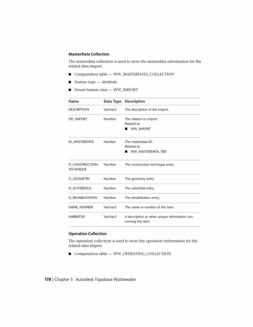
MasterData Collection
The masterdata collection is used to store the masterdata information for therelated data import.
■ Computation table — WW_MASTERDATA_COLLECTION
■ Feature type — Attribute
■ Parent feature class — WW_IMPORT
DescriptionData TypeName
The description of the import.Varchar2DESCRIPTION
The relation to import.NumberFID_IMPORTRelated to:
■ WW_IMPORT
The masterdata ID.NumberID_MASTERDATARelated to:
■ WW_MASTERDATA_TBD
The construction technique entry.NumberIS_CONSTRUCTION-TECHNIQUE
The geometry entry.NumberIS_GEOMETRY
The outerfield entry.NumberIS_OUTERFIELD
The rehabilitation entry.NumberIS_REHABILITATION
The name or number of this item.Varchar2NAME_NUMBER
A description or other unique information con-cerning this item.
Varchar2NARRATIVE
Operation Collection
The operation collection is used to store the operation information for therelated data import.
■ Computation table — WW_OPERATING_COLLECTION
178 | Chapter 3 Autodesk Topobase Wastewater

■ Feature type — Attribute
■ Parent feature class — WW_IMPORT
DescriptionData TypeName
The description of the import.Varchar2DESCRIPTION
The relation to import.NumberFID_IMPORTRelated to:
■ WW_IMPORT
The operation entry.NumberIS_OPERATION
The name or number of this item.Varchar2NAME_NUMBER
A description or other unique information con-cerning this item.
Varchar2NARRATIVE
Imported FeatureThis feature class stores all of the imported features, and the relationshipbetween sections, inspections and inspection collection.
■ Feature class — WW_IMPORTED_FEATURE
■ Feature type — Attribute
DescriptionData TypeName
The data matching state.NumberDATA_MATCH-ING_STATE
The feature class ID. TB_DICTION-ARY.F_CLASS_ID.
NumberF_CLASS_ID
The parent feature class ID.NumberF_CLASS_ID_PARENT
The feature ID (master data).NumberFID_FEATURERelated to:
■ WW_ACC_BASIN
Wastewater Feature Classes and Types | 179

DescriptionData TypeName
■ WW_BASIN
■ WW_COALESCENCE_SEP
■ WW_DISCHARGE
■ WW_DISPOSAL_TANK
■ WW_EMULSION_SPLIT
■ WW_FITTING
■ WW_FRENCH_DRAINS
■ WW_GREASE_TRAP
■ WW_GRIT_CHAMBER
■ WW_HYD_SECTION
■ WW_HYD_STORAGE_SITE
■ WW_HYD_PUMP
■ WW_HYD_DISCHARGE
■ WW_HYD_VALVE
■ WW_HYD_MANHOLE
■ WW_HYD_OUTFALL
■ WW_HYD_FREE_OUTFALL
■ WW_LINE
■ WW_MANHOLE
■ WW_MEASURING_STATION
■ WW_MISC_PLANT
■ WW_NEUTRALIZER
■ WW_OIL_WATER_SEP
■ WW_OUTERFIELD
■ WW_OUTFALL
■ WW_POINT
■ WW_PUMP
■ WW_RESTRICTOR
■ WW_SCREEN
■ WW_SECTION
■ WW_SITE
180 | Chapter 3 Autodesk Topobase Wastewater

DescriptionData TypeName
■ WW_SOIL_CHARACTERISTIC
■ WW_STARCH
■ WW_STRAINER
■ WW_SUB_DRAIN_AREA
■ WW_TREATMENT_PLANT
■ WW_VALVE
The relation to the hydraulic collection.NumberFID_HYDRAUL-IC_COLLECTION Related to:
■ WW_HYDRAULIC_COLLECTION
Optional. The relation to import.NumberFID_IMPORTRelated to:
■ WW_IMPORT
The relation to inspection.NumberFID_INSPECTIONRelated to:
■ WW_INSPECTION
The relation to the masterdata collection.NumberFID_MASTER-DATA_COLLECTION Related to:
■ WW_MASTERDATA_COLLECTION
The matched ID.NumberFID_MATCHED
The matched parent ID.NumberFID_MATCHED_PAR-ENT
The relation to the operating collection.NumberFID_OPERAT-ING_COLLECTION Related to:
■ WW_OPERATING_COLLECTION
The parent ID.NumberFID_PARENT
The ‘from’ manhole.Varchar2FROM_MANHOLE
Wastewater Feature Classes and Types | 181

DescriptionData TypeName
The matching attribute.Varchar2MATCHING_ATTRIB-UTE
The attribute used during conflict resolution.Varchar2RESOLVED_CON-FLICTS
The ‘to’ manhole.Varchar2TO_MANHOLE
InspectionThe Inspection topic contains feature classes which are related to the inspectionof a wastewater network.
ContractThe Contract feature class contains data that describes an inspection sessionand general information related to who performed the inspection, when theinspection occurred, etc.
■ Feature class — WW_CONTRACT
■ Feature type — Attribute
DescriptionData TypeName
The contract number of the inspection.Varchar2CONTRACT_NUM-BER
The contractor who will perform the inspection.Varchar2CONTRACTOR
The date when the contract was made.DateDATE_CONTRACT
The date when the inspection is completed.DateDATE_END_INSPEC-TION
A description of what the inspection will cover.Varchar2DESCRIPTION
The relation to inspection collection.NumberFID_INSPEC-TION_COLLECTION Related to:
182 | Chapter 3 Autodesk Topobase Wastewater

DescriptionData TypeName
■ WW_INSPECTION_COLLECTION
The relation to the masterdata collection.NumberFID_MASTER-DATA_COLLECTION Related to:
■ WW_MASTERDATA_COLLECTION
The coding system ID.NumberID_CODING_SYS-TEM Related to:
■ WW_CODING_SYSTEM_TBD
The rehabilitation contract ID.NumberID_CONTRACT_RE-HAB Related to:
■ WW_CONTRACT_REHAB_TBD
The contract typeID.NumberID_CONTRACT_TYPERelated to:
■ WW_CONTRACT_TYPE_TBD
The inspection purpose ID.NumberID_INSPECTION_PUR-POSE Related to:
■ WW_INSPECTION_PURPOSE_TBD
The identifier of the inspection contract.NumberIDCONTRACT
The inspection site.Varchar2INSPECTION_SITE
The object support value.Varchar2OBJECTSUPPORT
The quality control value.Varchar2QUALITYCONTROL
The site supervision value.Varchar2SITESUPERVISION
The name of the system.Varchar2SYSTEMNAME
The import version.Varchar2VERSION
Wastewater Feature Classes and Types | 183

FilmThe Film feature class contains information pertaining to the inspection videoassociated with the inspection. A film documents the inspection and allowthe inspector to see the section and the manhole during the inspection.
■ Feature class — WW_FILM
■ Feature type — Attribute
DescriptionData TypeName
The relation to inspection collection.NumberFID_INSPEC-TION_COLLECTION Related to:
■ WW_INSPECTION_COLLECTION
The film path.Varchar2FILMPATH
The film path actual (absolute).NumberFILMPATHACTUALAB-SOLUTE
The identifier of the inspection contract.NumberIDCONTRACT
The video archive reference.Varchar2VIDEOARCHIVEREFER-ENCE
Film Feature
The film feature is a film that corresponds to an inspected section.
■ Computation table — WW_FILM_FEATURE
■ Feature type — Attribute
■ Parent feature class — WW_FILM
DescriptionData TypeName
The feature ID.NumberFID_FEATURERelated to:
■ WW_SECTION
The film ID.NumberFID_FILM
184 | Chapter 3 Autodesk Topobase Wastewater

DescriptionData TypeName
Related to:
■ WW_FILM
The inspection direction ID.NumberID_INSPECTION_DIR-ECTION Related to:
■ WW_INSPECTION_DIRECTION_TBD
The name or number of this item.Varchar2NAME_NUMBER
Film Frame
The film frame is a single, still frame of a film.
■ Computation table — WW_FILM_FRAME
■ Feature type — Attribute
■ Parent feature class — WW_FILM
DescriptionData TypeName
The last frame of the inspection film.NumberEND_FRAME
The film ID.NumberFID_FILMRelated to:
■ WW_FILM
The frame rate at which the inspection video wascreated, measured in frames per second (fps).
NumberFPS
The first frame of the inspection film.NumberSTART_FRAME
Film Offset
The film offset is used to synchronize the MPEG frame number with a videotime counter.
■ Computation table — WW_FILM_OFFSET
■ Feature type — Attribute
Wastewater Feature Classes and Types | 185

■ Parent feature class — WW_FILM
DescriptionData TypeName
The film ID.NumberFID_FILMRelated to:
■ WW_FILM
The MPEG frame number.NumberMPEGFRAMENO
The TC frame number.NumberTCFRAMENO
InspectionThe Inspection feature class is the control for the wastewater networkcomponents (such as sections and manholes) which checks their operatingcapabilities.
■ Feature class — WW_INSPECTION
■ Feature type — Attribute
DescriptionData TypeName
The date when the inspection was made.DateDATE_INSPECTION
The relation to inspection collection.NumberFID_INSPEC-TION_COLLECTION Related to:
■ WW_INSPECTION_COLLECTION
The location to inspection (street).NumberFID_LOCATIONRelated to:
■ WW_LOCATION
The inspection direction ID.NumberID_INSPECTION_DIR-ECTION Related to:
■ WW_INSPECTION_DIRECTION_TBD
186 | Chapter 3 Autodesk Topobase Wastewater

DescriptionData TypeName
The inspection procedure ID.NumberID_INSPEC-TION_PROCEDURE Related to:
■ WW_INSPECTION_PROCEDURE_TBD
The inspection type ID.NumberID_INSPEC-TION_TYPE Related to:
■ WW_INSPECTION_TYPE_TBD
The piping type ID.NumberID_PIPING_TYPERelated to:
■ WW_PIPING_TYPE_TBD
The reference point position ID.NumberID_REF_POINT_POSI-TION Related to:
■ WW_REF_POINT_POSITION_TBD
The video reference ID.NumberID_VIDEO_REFER-ENCE Related to:
■ WW_VIDEO_REFERENCE_TBD
The video storage medium ID.NumberID_VIDEOSTOR-AGEMEDIUM Related to:
■ WW_VIDEOSTORAGEMEDIUM_TBD
The water drainage ID.NumberID_WATERDRAINAGERelated to:
■ WW_WATERDRAINAGE_TBD
The weather typeID.NumberID_WEATHER_TYPERelated to:
■ WW_WEATHER_TYPE_TBD
The identifier of the contract.NumberIDCONTRACT
The inspection group.NumberINSPECTION_GROUP
Wastewater Feature Classes and Types | 187

DescriptionData TypeName
The identifier of the contract.Varchar2INSPECTORNAME
The cleaned entry.NumberIS_CLEANED
The length of the inspection, measured in meters.NumberLENGTHOFINSPEC-TION
The name or number of this item.Varchar2NAME_NUMBER
Remarks pertaining to the inspection.Varchar2REMARKS
The temperature during the inspection.NumberTEMPERATURE
The time when the inspection was performed.DateTIME
The video archive reference.Varchar2VIDEOARCHIVEREFER-ENCE
Inspection Leakage Test
The inspection leakage test is used to store leakage test information of aninspected section. For example, the information may include detected corrosionor pitting of the section.
■ Computation table — WW_LEAKAGE_TEST
■ Feature type — Attribute
■ Parent feature class — WW_INSPECTION
DescriptionData TypeName
The date when the leakage test was performed.DateDATE_TEST
The device operator.Varchar2DEVICEOPERATOR
The inspection ID.NumberFID_INSPECTIONRelated to:
■ WW_INSPECTION
188 | Chapter 3 Autodesk Topobase Wastewater

DescriptionData TypeName
The test procedure ID.NumberID_TEST_PROCED-URE Related to:
■ WW_TEST_PROCEDURE_TBD
The test reason ID.NumberID_TEST_REASONRelated to:
■ WW_TEST_REASON_TBD
The test regulation ID.NumberID_TEST_REGULA-TION Related to:
■ WW_TEST_REGULATION_TBD
The test scope ID.NumberID_TEST_SCOPERelated to:
■ WW_TEST_SCOPE_TBD
The identifier of the contract.NumberIDCONTRACT
The successful entry.NumberIS_SUCCESFUL
Manhole Classification
Manhole classification is used to store all classification information related tothe inspection of a manhole.
■ Computation table — WW_MANHOLE_CLASSIFICATION
■ Feature type — Attribute
■ Parent feature class — WW_INSPECTION
DescriptionData TypeName
Additional points.NumberADDITIONALPOINTS
The authoritative damage value.Varchar2AUTHORITATIVEDAM-AGE
Wastewater Feature Classes and Types | 189

DescriptionData TypeName
The authoritative quantification value.NumberAUTHORITAT-IVEQUANTIFICATION
The automatic class value.NumberCLASSAUTOMATIC
The manual class value.NumberCLASSMANUAL
The date when the evaluation was performed.DateDATE_EVALUATION
The inspection ID.NumberFID_INSPECTIONRelated to:
■ WW_INSPECTION
The manhole ID.NumberFID_MANHOLERelated to:
■ WW_MANHOLE
■ WW_FITTING
The evaluation procedure ID.NumberID_EVAL_PROCED-URE Related to:
■ WW_EVAL_PROCEDURE_TBD
The final number.NumberNUMBERFINAL
The preliminary number.NumberNUMBERPRELIMIN-ARY
Manhole Observation
Manhole observation is used to store all observed information related to theinspection of a manhole.
■ Computation table — WW_MANHOLE_OBSERVE
■ Feature type — Collection
190 | Chapter 3 Autodesk Topobase Wastewater

■ Parent feature class — WW_INSPECTION
DescriptionData TypeName
The characterization 1 value.Varchar2CHARACTERIZA-TION1
The characterization 2 value.Varchar2CHARACTERIZA-TION2
The damage number.NumberDAMAGE_NUMBER
The inspection ID.NumberFID_INSPECTIONRelated to:
■ WW_INSPECTION
The manhole ID.NumberFID_MANHOLERelated to:
■ WW_MANHOLE
■ WW_FITTING
The manhole rehabilitation ID.NumberFID_MANHOLE_RE-HABILITATION Related to:
■ WW_MANHOLE_REHABILITATION
The frame value.Varchar2FRAME
The DAK clean up ID.NumberID_DAK_CLEAN_UPRelated to:
■ WW_DAK_CLEAN_UP_TBD
The DAL clean up ID.NumberID_DAL_CLEAN_UPRelated to:
■ WW_DAL_CLEAN_UP_TBD
The manhole area ID.NumberID_MANHOLE_AREARelated to:
■ WW_MANHOLE_AREA_TBD
Wastewater Feature Classes and Types | 191
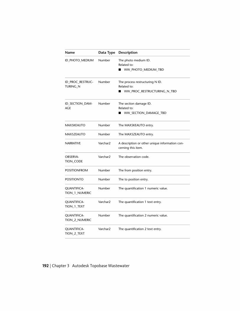
DescriptionData TypeName
The photo medium ID.NumberID_PHOTO_MEDIUMRelated to:
■ WW_PHOTO_MEDIUM_TBD
The process restructuring N ID.NumberID_PROC_RESTRUC-TURING_N Related to:
■ WW_PROC_RESTRUCTURING_N_TBD
The section damage ID.NumberID_SECTION_DAM-AGE Related to:
■ WW_SECTION_DAMAGE_TBD
The MAXSKEAUTO entry.NumberMAXSKEAUTO
The MAXSZEAUTO entry.NumberMAXSZEAUTO
A description or other unique information con-cerning this item.
Varchar2NARRATIVE
The observation code.Varchar2OBSERVA-TION_CODE
The from position entry.NumberPOSITIONFROM
The to position entry.NumberPOSITIONTO
The quantification 1 numeric value.NumberQUANTIFICA-TION_1_NUMERIC
The quantification 1 text entry.Varchar2QUANTIFICA-TION_1_TEXT
The quantification 2 numeric value.NumberQUANTIFICA-TION_2_NUMERIC
The quantification 2 text entry.Varchar2QUANTIFICA-TION_2_TEXT
192 | Chapter 3 Autodesk Topobase Wastewater

DescriptionData TypeName
The rehabilitation designation.Varchar2REHABILITA-TION_DESIGNATION
The SKBE auto entry.NumberSKBEAUTO
The SKBV auto entry.NumberSKBVAUTO
The SKBV manual entry.NumberSKBVMANU
The SKDE auto entry.NumberSKDEAUTO
The AKDV auto entry.NumberSKDVAUTO
The SKDV manual entry.NumberSKDVMANU
The SKSE auto entry.NumberSKSEAUTO
The SKSV auto entry.NumberSKSVAUTO
The SKSV manual entry.NumberSKSVMANU
Standard annotation used only for DWA classific-ation.
Varchar2STANDARD_AN-NOTATION_DWA
The restructuring status.NumberSTATUS_RESTRUC-TURING
The SZBE auto entry.NumberSZBEAUTO
The SZBV auto entry.NumberSZBVAUTO
The SZDE auto entry.NumberSZDEAUTO
The SZDV auto entry.NumberSZDVAUTO
The SZSE auto entry.NumberSZSEAUTO
The SZSV auto entry.NumberSZSVAUTO
The time code.Varchar2TIMECODE
Wastewater Feature Classes and Types | 193

DescriptionData TypeName
The vertical position value.NumberVERTICALPOSITION
The video counter.Varchar2VIDEO_COUNTER
Manhole Rehabilitation
Manhole rehabilitation is used to indicate when a damaged, deteriorated, orworn item needs rehabilitation.
■ Computation table — WW_MANHOLE_REHABILITATION
■ Feature type — Attribute
■ Parent feature class — WW_INSPECTION
DescriptionData TypeName
The chemical resistance value.Varchar2CHEMICALRESIST-ANCE
The first clear width, measured in square meters.NumberCLEAR_WIDTH_1
The second clear width, measured in squaremeters.
NumberCLEAR_WIDTH_2
The acceptance date for the manhole rehabilita-tion.
DateDATE_ACCEPTANCE
The completion date for the manhole rehabilita-tion.
DateDATE_COMPLETION
The date when the manhole rehabilitation begins.DateDATE_STARTUP
The end stationing entry.NumberEND_STATIONNING
The relation with contract.NumberFID_CONTRACTRelated to:
■ WW_CONTRACT
The manhole ID.NumberFID_MANHOLERelated to:
194 | Chapter 3 Autodesk Topobase Wastewater

DescriptionData TypeName
■ WW_MANHOLE
The flexible module.NumberFLEXIBLEE_MODULE
The flexural strength.NumberFLEXUR-AL_STRENGTH
The doc direction ID.NumberID_DOC_DIRECTIONRelated to:
■ WW_DOC_DIRECTION_TBD
The load ID.NumberID_LOADRelated to:
■ WW_LOAD_TBD
The material ID.NumberID_MATERIALRelated to:
■ WW_MATERIAL_TBD
The material bond 1 ID.NumberID_MATERI-AL_BOND_1 Related to:
■ WW_MATERIAL_BOND_TBD
The material bond 2 ID.NumberID_MATERI-AL_BOND_2 Related to:
■ WW_MATERIAL_BOND_TBD
The profile ID.NumberID_PROFILERelated to:
■ WW_PROFILE_TBD
The rehabilitation scope ID.NumberID_REHABILITA-TION_SCOPE Related to:
■ WW_REHABILITATION_SCOPE_TBD
Wastewater Feature Classes and Types | 195

DescriptionData TypeName
The rehabilitation type ID.NumberID_REHABILITA-TION_TYPE Related to:
■ WW_REHABILITATION_TYPE_TBD
The site part ID.NumberID_SITE_PARTRelated to:
■ WW_SITE_PART_TBD
The water permeability ID.NumberID_WATER_PERMEAB-ILITY Related to:
■ WW_WATER_PERMEABILITY_TBD
The leakage test entry.NumberIS_LEAKAGE_TEST
The material strength value.NumberMATERI-AL_STRENGTH
The name or number of this item.Varchar2NAME_NUMBER
A description or other unique information con-cerning this item.
Varchar2NARRATIVE
The narrative position value.Varchar2NARRATIVE_POSI-TION
The from position entry.NumberPOSITIONFROM
The to position entry.NumberPOSITIONTO
The rehabiliation period.NumberREHABILITA-TION_PERIOD
The ring rigidity value.NumberRING_RIGIDITY
The start stationing entry.NumberSTART_STATIONING
The wall thickness value.NumberWALL_THICKNESS
The date when the warranty ends.DateWARRANTY_END
196 | Chapter 3 Autodesk Topobase Wastewater
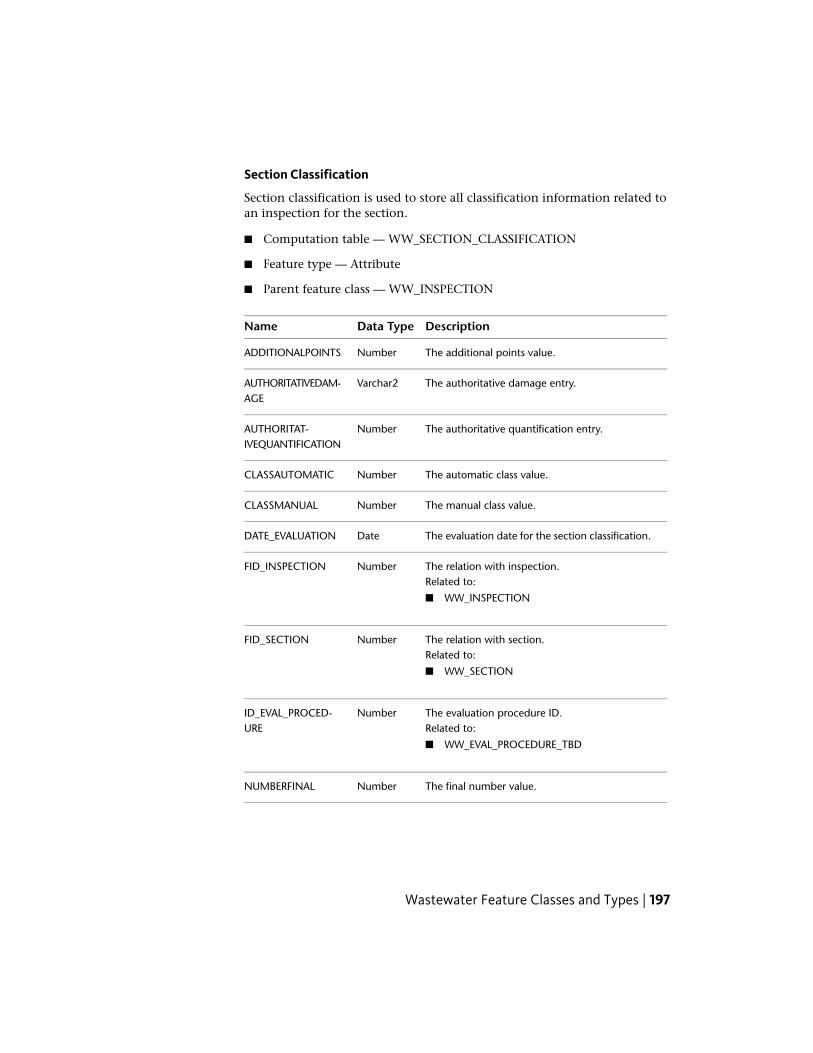
Section Classification
Section classification is used to store all classification information related toan inspection for the section.
■ Computation table — WW_SECTION_CLASSIFICATION
■ Feature type — Attribute
■ Parent feature class — WW_INSPECTION
DescriptionData TypeName
The additional points value.NumberADDITIONALPOINTS
The authoritative damage entry.Varchar2AUTHORITATIVEDAM-AGE
The authoritative quantification entry.NumberAUTHORITAT-IVEQUANTIFICATION
The automatic class value.NumberCLASSAUTOMATIC
The manual class value.NumberCLASSMANUAL
The evaluation date for the section classification.DateDATE_EVALUATION
The relation with inspection.NumberFID_INSPECTIONRelated to:
■ WW_INSPECTION
The relation with section.NumberFID_SECTIONRelated to:
■ WW_SECTION
The evaluation procedure ID.NumberID_EVAL_PROCED-URE Related to:
■ WW_EVAL_PROCEDURE_TBD
The final number value.NumberNUMBERFINAL
Wastewater Feature Classes and Types | 197
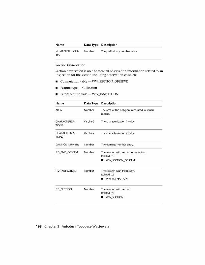
DescriptionData TypeName
The preliminary number value.NumberNUMBERPRELIMIN-ARY
Section Observation
Section obversation is used to store all observation information related to aninspection for the section including observation code, etc.
■ Computation table — WW_SECTION_OBSERVE
■ Feature type — Collection
■ Parent feature class — WW_INSPECTION
DescriptionData TypeName
The area of the polygon, measured in squaremeters.
NumberAREA
The characterization 1 value.Varchar2CHARACTERIZA-TION1
The characterization 2 value.Varchar2CHARACTERIZA-TION2
The damage number entry.NumberDAMAGE_NUMBER
The relation with section observation.NumberFID_END_OBSERVERelated to:
■ WW_SECTION_OBSERVE
The relation with inspection.NumberFID_INSPECTIONRelated to:
■ WW_INSPECTION
The relation with section.NumberFID_SECTIONRelated to:
■ WW_SECTION
198 | Chapter 3 Autodesk Topobase Wastewater

DescriptionData TypeName
The relation with section rehabilitation.NumberFID_SECTION_REHAB-ILITATION Related to:
■ WW_SECTION_REHABILITATION
The frame entry.Varchar2FRAME
The BAK clean up ID.NumberID_BAK_CLEAN_UPRelated to:
■ WW_BAK_CLEAN_UP_TBD
The BAL clean up ID.NumberID_BAL_CLEAN_UPRelated to:
■ WW_BAL_CLEAN_UP_TBD
The cancellation reason ID.NumberID_CANCELLA-TION_REASON Related to:
■ WW_CANCELLATION_REASON_TBD
The photo medium ID.NumberID_PHOTO_MEDIUMRelated to:
■ WW_PHOTO_MEDIUM_TBD
The process restructuring ID.NumberID_PROC_RESTRUC-TURING Related to:
■ WW_PROC_RESTRUCTURING_TBD
The section damage ID.NumberID_SECTION_DAM-AGE Related to:
■ WW_SECTION_DAMAGE_TBD
The connection entry.NumberIS_CONNECTION
The MAXSKEAUTO entry.NumberMAXSKEAUTO
The MAXSZEAUTO entry.NumberMAXSZEAUTO
Wastewater Feature Classes and Types | 199

DescriptionData TypeName
A description or other unique information con-cerning this item.
Varchar2NARRATIVE
The observation code.Varchar2OBSERVA-TION_CODE
The position value.NumberPOSITION
The from position entry.NumberPOSITIONFROM
The to position entry.NumberPOSITIONTO
The first numeric quantification value.NumberQUANTIFICA-TION_1_NUMERIC
The first text quantification value.Varchar2QUANTIFICA-TION_1_TEXT
The second numeric quantification value.NumberQUANTIFICA-TION_2_NUMERIC
The second text quantification value.Varchar2QUANTIFICA-TION_2_TEXT
The rehabiliation designation.Varchar2REHABILITA-TION_DESIGNATION
The SKBE auto entry.NumberSKBEAUTO
The SKBV auto entry.NumberSKBVAUTO
The SKBV manual entry.NumberSKBVMANU
The SKDE auto entry.NumberSKDEAUTO
The AKDV auto entry.NumberSKDVAUTO
The SKDV manual entry.NumberSKDVMANU
The SKSE auto entry.NumberSKSEAUTO
200 | Chapter 3 Autodesk Topobase Wastewater

DescriptionData TypeName
The SKSV auto entry.NumberSKSVAUTO
The SKSV manual entry.NumberSKSVMANU
Standard annotation used only for DWA classific-ation.
Varchar2STANDARD_AN-NOTATION_DWA
The restructuring status.NumberSTATUS_RESTRUC-TURING
The SZBE auto entry.NumberSZBEAUTO
The SZBV auto entry.NumberSZBVAUTO
The SZDE auto entry.NumberSZDEAUTO
The SZDV auto entry.NumberSZDVAUTO
The SZSE auto entry.NumberSZSEAUTO
The SZSV auto entry.NumberSZSVAUTO
The time code.Varchar2TIMECODE
The video counter.Varchar2VIDEO_COUNTER
Section Rehabilitation
Section rehabilitation is used to indicate when a damaged, deteriorated, orworn item needs rehabilitation.
■ Computation table — WW_SECTION_REHABILITATION
■ Feature type — Attribute
■ Parent feature class — WW_INSPECTION
DescriptionData TypeName
The chemical resistance value.Varchar2CHEMICALRESIST-ANCE
Wastewater Feature Classes and Types | 201

DescriptionData TypeName
The first clear width, measured in square meters.NumberCLEAR_WIDTH_1
The second clear width, measured in squaremeters.
NumberCLEAR_WIDTH_2
The acceptance date for the manhole rehabilita-tion.
DateDATE_ACCEPTANCE
The completion date for the manhole rehabilita-tion.
DateDATE_COMPLETION
The date when the manhole rehabilitation begins.DateDATE_STARTUP
The end stationing value.NumberEND_STATIONNING
The relation with contract.NumberFID_CONTRACTRelated to:
■ WW_CONTRACT
The manhole ID.NumberFID_SECTIONRelated to:
■ WW_SECTION
The flexible module.NumberFLEXIBLEE_MODULE
The flexural strength.NumberFLEXUR-AL_STRENGTH
The doc direction ID.NumberID_DOC_DIRECTIONRelated to:
■ WW_DOC_DIRECTION_TBD
The load ID.NumberID_LOADRelated to:
■ WW_LOAD_TBD
The material ID.NumberID_MATERIALRelated to:
202 | Chapter 3 Autodesk Topobase Wastewater

DescriptionData TypeName
■ WW_MATERIAL_TBD
The material bond 1 ID.NumberID_MATERI-AL_BOND_1 Related to:
■ WW_MATERIAL_BOND_TBD
The material bond 2 ID.NumberID_MATERI-AL_BOND_2 Related to:
■ WW_MATERIAL_BOND_TBD
The profile ID.NumberID_PROFILERelated to:
■ WW_PROFILE_TBD
The rehabilitation scope ID.NumberID_REHABILITA-TION_SCOPE Related to:
■ WW_REHABILITATION_SCOPE_TBD
The rehabilitation type ID.NumberID_REHABILITA-TION_TYPE Related to:
■ WW_REHABILITATION_TYPE_TBD
The site part ID.NumberID_SITE_PARTRelated to:
■ WW_SITE_PART_TBD
The water permeability ID.NumberID_WATER_PERMEAB-ILITY Related to:
■ WW_WATER_PERMEABILITY_TBD
The leakage test entry.NumberIS_LEAKAGE_TEST
The material strength value.NumberMATERI-AL_STRENGTH
Wastewater Feature Classes and Types | 203

DescriptionData TypeName
The name or number of this item.Varchar2NAME_NUMBER
A description or other unique information con-cerning this item.
Varchar2NARRATIVE
The narrative position entry.Varchar2NARRATIVE_POSI-TION
The from position entry.NumberPOSITIONFROM
The to position entry.NumberPOSITIONTO
The rehabiliation period.NumberREHABILITA-TION_PERIOD
The ring rigidity value.NumberRING_RIGIDITY
The start stationing value.NumberSTART_STATIONING
The wall thickness value.NumberWALL_THICKNESS
The date when the warranty ends.DateWARRANTY_END
Site Observation
Site obversation is used to store all observation information related to aninspection for the site.
■ Computation table — WW_SITE_OBSERVE
■ Feature type — Collection
■ Parent feature class — WW_INSPECTION
DescriptionData TypeName
The area of the polygon, measured in squaremeters.
NumberAREA
The feature ID.NumberFID_FEATURERelated to:
■ WW_ACC_BASIN
204 | Chapter 3 Autodesk Topobase Wastewater

DescriptionData TypeName
■ WW_BASIN
■ WW_DISCHARGE
■ WW_DISPOSAL_TANK
■ WW_EMULSION_SPLIT
■ WW_FITTING
■ WW_FRENCH_DRAINS
■ WW_MISC_PLANT
■ WW_OUTFALL
■ WW_PUMP
■ WW_RESTRICTOR
■ WW_SCREEN
■ WW_SITE
■ WW_STARCH
■ WW_STRAINER
■ WW_TREATMENT_PLANT
■ WW_VALVE
The relation with inspection.NumberFID_INSPECTIONRelated to:
■ WW_INSPECTION
The relation with section rehabilitation.NumberFID_SITE_REHABILIT-ATION Related to:
■ WW_SITE_REHABILITATION
The photo medium ID.NumberID_PHOTO_MEDIUMRelated to:
■ WW_PHOTO_MEDIUM_TBD
A description or other unique information con-cerning this item.
Varchar2NARRATIVE
Wastewater Feature Classes and Types | 205

DescriptionData TypeName
The rehabiliation designation.Varchar2REHABILITA-TION_DESIGNATION
Site Rehabilitation
Site rehabilitation is used to indicate when a damaged, deteriorated, or wornitem needs rehabilitation.
■ Computation table — WW_SITE_REHABILITATION
■ Feature type — Attribute
■ Parent feature class — WW_INSPECTION
DescriptionData TypeName
The chemical resistance value.Varchar2CHEMICALRESIST-ANCE
The first clear width, measured in square meters.NumberCLEAR_WIDTH_1
The second clear width, measured in squaremeters.
NumberCLEAR_WIDTH_2
The acceptance date for the manhole rehabilita-tion.
DateDATE_ACCEPTANCE
The completion date for the manhole rehabilita-tion.
DateDATE_COMPLETION
The date when the manhole rehabilitation begins.DateDATE_STARTUP
The end stationing entry.NumberEND_STATIONNING
The relation with contract.NumberFID_CONTRACTRelated to:
■ WW_CONTRACT
The manhole ID.NumberFID_SITERelated to:
■ WW_SITE
206 | Chapter 3 Autodesk Topobase Wastewater
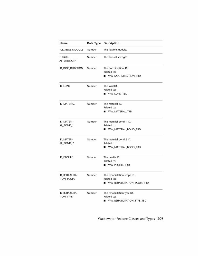
DescriptionData TypeName
The flexible module.NumberFLEXIBLEE_MODULE
The flexural strength.NumberFLEXUR-AL_STRENGTH
The doc direction ID.NumberID_DOC_DIRECTIONRelated to:
■ WW_DOC_DIRECTION_TBD
The load ID.NumberID_LOADRelated to:
■ WW_LOAD_TBD
The material ID.NumberID_MATERIALRelated to:
■ WW_MATERIAL_TBD
The material bond 1 ID.NumberID_MATERI-AL_BOND_1 Related to:
■ WW_MATERIAL_BOND_TBD
The material bond 2 ID.NumberID_MATERI-AL_BOND_2 Related to:
■ WW_MATERIAL_BOND_TBD
The profile ID.NumberID_PROFILERelated to:
■ WW_PROFILE_TBD
The rehabilitation scope ID.NumberID_REHABILITA-TION_SCOPE Related to:
■ WW_REHABILITATION_SCOPE_TBD
The rehabilitation type ID.NumberID_REHABILITA-TION_TYPE Related to:
■ WW_REHABILITATION_TYPE_TBD
Wastewater Feature Classes and Types | 207

DescriptionData TypeName
The site part ID.NumberID_SITE_PARTRelated to:
■ WW_SITE_PART_TBD
The water permeability ID.NumberID_WATER_PERMEAB-ILITY Related to:
■ WW_WATER_PERMEABILITY_TBD
The leakage test entry.NumberIS_LEAKAGE_TEST
The material strength value.NumberMATERI-AL_STRENGTH
The name or number of this item.Varchar2NAME_NUMBER
A description or other unique information con-cerning this item.
Varchar2NARRATIVE
The narrative position value.Varchar2NARRATIVE_POSI-TION
The from position entry.NumberPOSITIONFROM
The to position entry.NumberPOSITIONTO
The rehabiliation period.NumberREHABILITA-TION_PERIOD
The ring rigidity value.NumberRING_RIGIDITY
The start stationing entry.NumberSTART_STATIONING
The wall thickness value.NumberWALL_THICKNESS
The date when the warranty ends.DateWARRANTY_END
208 | Chapter 3 Autodesk Topobase Wastewater

MiscellaneousThe Miscellaneous topic contains feature classes which are related toenvironmental parameter, maintenance, markers, outerfields, and filtrationand sludge beds.
Env ParameterEnv parameters are pieces of information that include the wastewater type,the soil type, ground water distribution, or water protection area.
■ Computation table — WW_ENV_PARAMETERS
■ Feature type — Attribute
DescriptionData TypeName
The ground water distribution ID.NumberID_GROUND_WA-TER_DIST Related to:
■ WW_GROUND_WATER_DIST_TBD
The soil type ID.NumberID_SOIL_TYPERelated to:
■ WW_SOIL_TYPE_TBD
The wastewater soil type ID.NumberID_WASTEWA-TER_SOL_TYPE Related to:
■ WW_WASTEWATER_SOL_TYPE_TBD
The wastewater type ID.NumberID_WASTEWA-TER_TYPE Related to:
■ WW_WASTEWATER_TYPE_TBD
The water protection area ID.NumberID_WA-TER_PROT_AREA Related to:
■ WW_WATER_PROT_AREA_TBD
Wastewater Feature Classes and Types | 209

Filtration BedA below-grade system consisting of perforated piping installed in sand, gravelbeds, or trenches designed to permit the uniform distribution and absorptionor effluent from a septic tank or aerobic unit into the soil.
■ Computation table — WW_FILTRATION_BED
■ Feature type — Polygon
DescriptionData TypeName
The area of the filtration bed, measured in squaremeters.
NumberAREA
The date when the item was created.DateDATE_CREATION
The concessionaire of this item.NumberFID_CONSESSION-AIRE Related to:
■ WW_CONTACT
The enterprise in charge of building the item.Related to:
NumberFID_INSTALLER
■ WW_CONTACT
The company that is responsible for the mainten-ance of this item.
NumberFID_MAINTENANCE
Related to:
■ WW_CONTACT
The operator of this itemNumberFID_OPERATORRelated to:
■ WW_CONTACT
The owner of this itemNumberFID_OWNERRelated to:
■ WW_CONTACT
The name or number of this item.Varchar2NAME_NUMBER
210 | Chapter 3 Autodesk Topobase Wastewater

DescriptionData TypeName
A description or other unique information con-cerning this item.
Varchar2NARRATIVE
An operator defined work area. This attribute isused by the operator for user defined system
Varchar2USER_FLAG
processes. It does not effect the subject item'sdata integrity and should not be used to storethe subject item's data.
MaintenanceYou can administer maintenance work for all wastewater network features,except the intermediate points. The Maintenance feature class storesinformation about completed maintenance work. The feature class uses themaintenance type domain table. In the basic wastewater application, thisdomain table only contains general maintenance types. It can easily beenhanced to meet the requirements of the customized wastewater application.
■ Computation table — WW_MAINTENANCE
■ Feature type — Attribute
DescriptionData TypeName
The relation with network points and lines.Related to:
NumberFID_FEATURE
■ WW_ANODE
■ WW_ANODE_TEST_STATION
■ WW_CASING
■ WW_COVER
■ WW_DISCHARGE
■ WW_DISPOSAL_TANK
■ WW_FILTRATION_BED
■ WW_FITTING
■ WW_GREASE_TRAP
■ WW_GRIT_CHAMBER
■ WW_HOUSE_CONNECTOR
Wastewater Feature Classes and Types | 211

DescriptionData TypeName
■ WW_INTERMEDIATE_POINT
■ WW_LAGOON
■ WW_MANHOLE
■ WW_MARKER
■ WW_METER
■ WW_NEUTRALIZER
■ WW_OIL_WATER_SEP
■ WW_OUTFALL
■ WW_PUMP
■ WW_SECTION
■ WW_SEPTIC_TANK
■ WW_SITE
■ WW_SLUDGE_BED
■ WW_TREATMENT_PLANT
■ WW_VALVE
The type of maintenance for this item.NumberID_MAINTEN-ANCE_TYPE Related to:
■ WW_MAINTENANCE_TYPE_TBD
The date when the maintenance occurred.DateMAINTEN-ANCE_DATE
The date when the next maintenance is sched-uled.
DateMAINTEN-ANCE_NEXT_DATE
The maintenance period [day].NumberMAINTENANCE_PERI-OD
The name or number of this item.Varchar2NAME_NUMBER
A description or other unique information con-cerning this item.
Varchar2NARRATIVE
212 | Chapter 3 Autodesk Topobase Wastewater

DescriptionData TypeName
An operator defined work area. This attribute isused by the operator for user defined system
Varchar2USER_FLAG
processes. It does not effect the subject item'sdata integrity and should not be used to storethe subject item's data.
MarkerA sign, or concrete monument installed either directly above or immediatelyadjacent to undergroud lines, bends, or fittings to indicate the presence ofwaste water.
■ Computation table — WW_MARKER
■ Feature type — Point
DescriptionData TypeName
The date when the data was acquired.DateDATE_ACQUIRED
The date when the item was created.DateDATE_CREATION
The date when responsibility of the item wastaken.
DateDATE_STARTUP
The concessionaire of this item.NumberFID_CONSESSION-AIRE Related to:
■ WW_CONTACT
The relation with network points and lines.Related to:
NumberFID_FEATURE
■ WW_ANODE
■ WW_ANODE_TEST_STATION
■ WW_COVER
■ WW_DISCHARGE
■ WW_DISPOSAL_TANK
■ WW_FILTRATION_BED
Wastewater Feature Classes and Types | 213

DescriptionData TypeName
■ WW_FITTING
■ WW_GREASE_TRAP
■ WW_GRIT_CHAMBER
■ WW_HOUSE_CONNECTOR
■ WW_INTERMEDIATE_POINT
■ WW_LAGOON
■ WW_MANHOLE
■ WW_MARKER
■ WW_METER
■ WW_NEUTRALIZER
■ WW_OIL_WATER_SEP
■ WW_OUTFALL
■ WW_PROTECTION_AREA
■ WW_PUMP
■ WW_SEPTIC_TANK
■ WW_SITE
■ WW_SLUDGE_BED
■ WW_TREATMENT_PLANT
■ WW_VALVE
The enterprise in charge of building the item.Related to:
NumberFID_INSTALLER
■ WW_CONTACT
The location of the item (street).Related to:
NumberFID_LOCATION
■ WW_LOCATION
The company that is responsible for the mainten-ance of this item.
NumberFID_MAINTENANCE
Related to:
■ WW_CONTACT
214 | Chapter 3 Autodesk Topobase Wastewater

DescriptionData TypeName
The manufacturer of this item.NumberFID_MANUFAC-TURER Related to:
■ WW_CONTACT
The operator of this itemNumberFID_OPERATORRelated to:
■ WW_CONTACT
The owner of this itemNumberFID_OWNERRelated to:
■ WW_CONTACT
The date when the maintenance occurred.NumberGROUND_ELEVA-TION
The house number.Varchar2HOUSE
The house number supplement.Varchar2HOUSE_SUPPLE-MENT
How the current position of the item was determ-ined. For example, exactly, by positioning, un-known, or inexactly.
NumberID_ACCURACY
Related to:
■ WW_ACCURACY_TBD
The condition of the item. For example, broken,leaking, etc.
NumberID_CONDITION
Related to:
■ WW_CONDITION_TBD
The state of the disposition of the item. For ex-ample, death, planed, etc.
NumberID_DISPOSI-TION_STATE
Related to:
■ WW_DISPOSITION_STATE_TBD
Wastewater Feature Classes and Types | 215

DescriptionData TypeName
The type of foundation for this item.NumberID_FOUNDATIONRelated to:
■ WW_FOUNDATION_TBD
How the item is used.NumberID_FUNCTIONRelated to:
■ WW_MARKER_FUNCTION_TBD
The type of material composition of the anodeor anode packet.
NumberID_MATERIAL
Related to:
■ WW_MATERIAL_TBD
The material composition of the pole. For ex-amplel wood, steel, concrete, etc.
NumberID_POLE_MATERIAL
Related to:
■ WW_MARKER_POLE_MAT_TBD
The condition of the rock relative to the rocksstrength and integrity. For example, high, low,or medium.
NumberID_ROCK_CONDI-TION
Related to:
■ WW_MARKER_ROCK_COND_TBD
The material composition of the sign. For ex-ample, concrete, wood, etc.
NumberID_SIGN_MATERIAL
Related to:
■ WW_MATERIAL_TBD
The soil condition indicating the soil's strengthand integrity.
NumberID_SOIL_CONDI-TION
Related to:
■ WW_SOIL_CONDITION_TBD
A brief description of where the item is located.For example, 1m from the wall.
Varchar2LOCATION
216 | Chapter 3 Autodesk Topobase Wastewater

DescriptionData TypeName
The name or number of this item.Varchar2NAME_NUMBER
A description or other unique information con-cerning this item.
Varchar2NARRATIVE
The depth, in meters, that the pole is buried intothe foundation; usually the ground surface.
NumberPOLE_DEPTH
The distance, in meters, that the pole extendsabove the foundation; usually the ground surface.
NumberPOLE_HEIGHT
The quality of the sign.NumberQUALITY
The height dimension of the sign.NumberSIGN_HEIGHT
The text on the sign.NumberSIGN_TEXT
The width dimension of the sign.NumberSIGN_WIDTH
An operator defined work area. This attribute isused by the operator for user defined system
Varchar2USER_FLAG
processes. It does not effect the subject item'sdata integrity and should not be used to storethe subject item's data.
A short description of the model. This value isused for the domain table representation of themodel.
Varchar2VALUE
OuterField■ Computation table — WW_OUTERFIELD
■ Feature type — Point
DescriptionData TypeName
The date when water reached its highest mark.DateDATE_HIGHWASSER
The explanation of this item.Varchar2EXPLANATION
Wastewater Feature Classes and Types | 217

DescriptionData TypeName
The relation to masterdata collection.NumberFID_MASTER-DATA_COLLECTION Related to:
■ WW_MASTERDATA_COLLECTION
The inclination ID.NumberID_INCLINATIONRelated to:
■ WW_INCLINATION_TBD
The point attribute ID.NumberID_POINT_ATTRIB-UTE Related to:
■ WW_POINT_ATTRIBUTE_TBD
The utilization ID.NumberID_UTILIZATIONRelated to:
■ WW_UTILIZATION_TBD
The water protection area ID.NumberID_WA-TER_PROT_AREA Related to:
■ WW_WATER_PROT_AREA_TBD
The maximum high water level.NumberMAX_HIGHWASSER
The name or number of this item.Varchar2NAME_NUMBER
A description or other unique information con-cerning this item.
Varchar2NARRATIVE
Qtygkfvalue.NumberQTYGKFVALUE
The soil type quality.Varchar2QTYSOILTYPE
The quality of the point.NumberQUALITY
218 | Chapter 3 Autodesk Topobase Wastewater
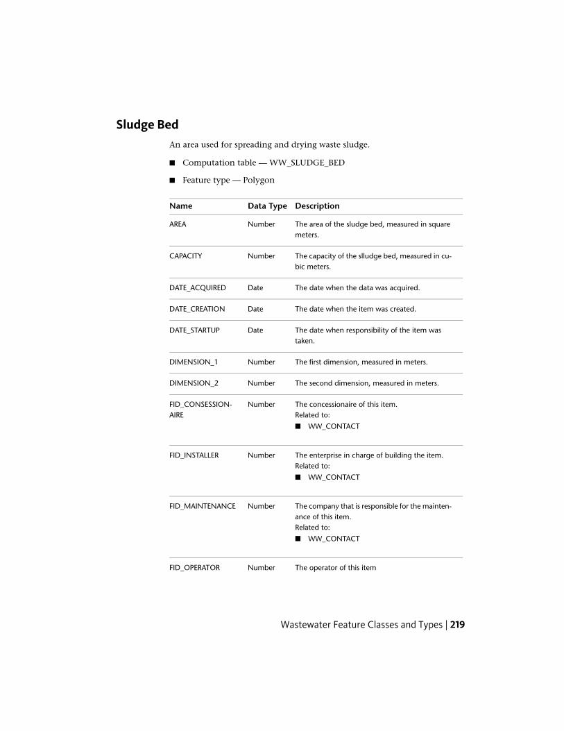
Sludge BedAn area used for spreading and drying waste sludge.
■ Computation table — WW_SLUDGE_BED
■ Feature type — Polygon
DescriptionData TypeName
The area of the sludge bed, measured in squaremeters.
NumberAREA
The capacity of the slludge bed, measured in cu-bic meters.
NumberCAPACITY
The date when the data was acquired.DateDATE_ACQUIRED
The date when the item was created.DateDATE_CREATION
The date when responsibility of the item wastaken.
DateDATE_STARTUP
The first dimension, measured in meters.NumberDIMENSION_1
The second dimension, measured in meters.NumberDIMENSION_2
The concessionaire of this item.NumberFID_CONSESSION-AIRE Related to:
■ WW_CONTACT
The enterprise in charge of building the item.Related to:
NumberFID_INSTALLER
■ WW_CONTACT
The company that is responsible for the mainten-ance of this item.
NumberFID_MAINTENANCE
Related to:
■ WW_CONTACT
The operator of this itemNumberFID_OPERATOR
Wastewater Feature Classes and Types | 219
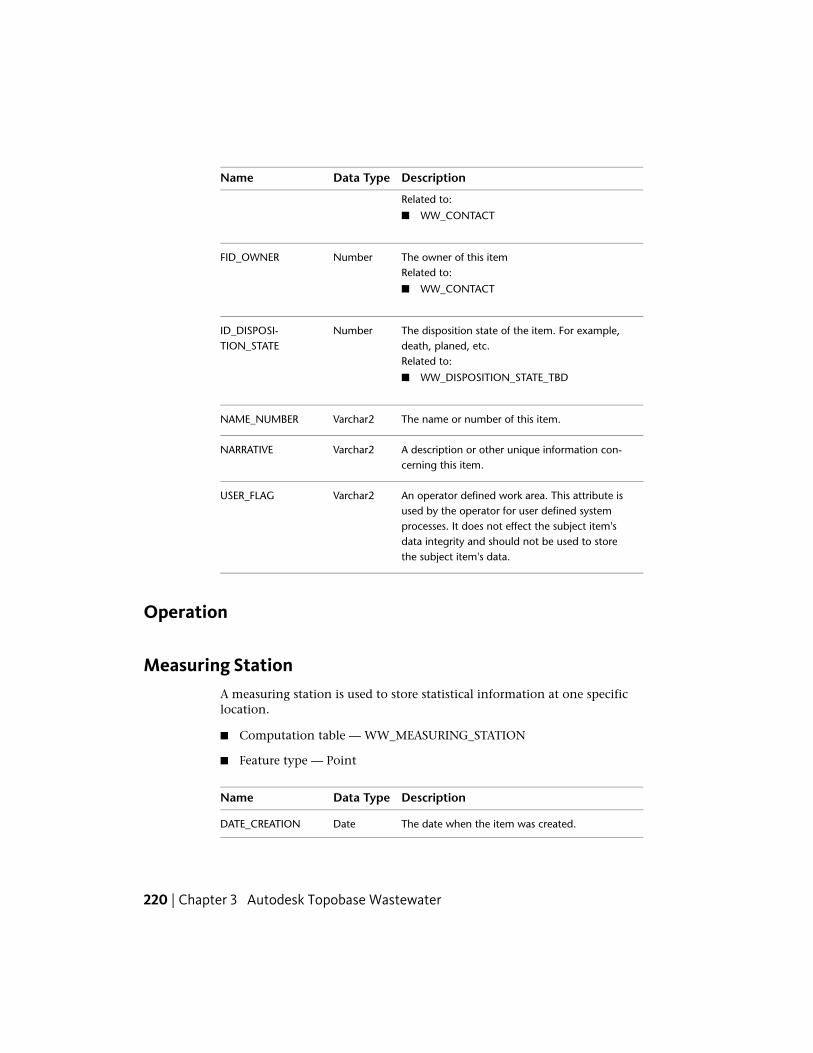
DescriptionData TypeName
Related to:
■ WW_CONTACT
The owner of this itemNumberFID_OWNERRelated to:
■ WW_CONTACT
The disposition state of the item. For example,death, planed, etc.
NumberID_DISPOSI-TION_STATE
Related to:
■ WW_DISPOSITION_STATE_TBD
The name or number of this item.Varchar2NAME_NUMBER
A description or other unique information con-cerning this item.
Varchar2NARRATIVE
An operator defined work area. This attribute isused by the operator for user defined system
Varchar2USER_FLAG
processes. It does not effect the subject item'sdata integrity and should not be used to storethe subject item's data.
Operation
Measuring StationA measuring station is used to store statistical information at one specificlocation.
■ Computation table — WW_MEASURING_STATION
■ Feature type — Point
DescriptionData TypeName
The date when the item was created.DateDATE_CREATION
220 | Chapter 3 Autodesk Topobase Wastewater

DescriptionData TypeName
The depth of the filter, measured in meters.NumberDEPTH_FILTER
The diameter, measured in meters.NumberDIAMETER
The edge elevation, measured in meters.NumberELEVATION_EDGE
The end of the filter.NumberEND_FILTER
The relation to the operating collectionNumberFID_OPERAT-ING_COLLECTION Related to:
■ WW_OPERATING_COLLECTION
How the current position of the item was determ-ined. For example, exactly, by positioning, un-known, or inexactly.
NumberID_ACCURACY
Related to:
■ WW_ACCURACY_TBD
The cycle ID.NumberID_CYCLERelated to:
■ WW_CYCLE_TBD
The name or number of this item.Varchar2NAME_NUMBER
A description or other unique information con-cerning this item.
Varchar2NARRATIVE
The orientation of the measuring station.NumberORIENTATION
The description of the outerfield .Varchar2OUTERFIELD_DE-SCRIPTION
The characteristics of the soil.Varchar2SOIL_CHARACTERIST-IC
The start of the filter.NumberSTART_FILTER
Wastewater Feature Classes and Types | 221

Measuring
The measuring feature class is used for storing the measured values of themeasuring station.
■ Computation table — WW_MEASURING
■ Feature type — Attribute
■ Parent feature class — WW_MEASURING_STATION
DescriptionData TypeName
The date when the data was acquired.DateDATE_ACQUIRED
The relation to the measuring stationNumberFID_MEASUR-ING_STATION Related to:
■ WW_MEASURING_STATION
The measured value.NumberMEASURED_VALUE
A description or other unique information con-cerning this item.
Varchar2NARRATIVE
Soil CharacteristicThe soil characteristic feature class is used for storing statistical informationabout the soil at one specific location.
■ Computation table — WW_SOIL_CHARACTERISTIC
■ Feature type — Point
DescriptionData TypeName
The relation to the operating collection.NumberFID_OPERAT-ING_COLLECTION Related to:
■ WW_OPERATING_COLLECTION
The ground distance, measured in meters.NumberGW_DISTANCE
222 | Chapter 3 Autodesk Topobase Wastewater

DescriptionData TypeName
How the current position of the item was determ-ined. For example, exactly, by positioning, un-known, or inexactly.
NumberID_ACCURACY
Related to:
■ WW_ACCURACY_TBD
The analysis type ID.NumberID_ANALYSIS_TYPERelated to:
■ WW_ANALYSIS_TYPE_TBD
The KF value.NumberKFVALUE
The name or number of this item.Varchar2NAME_NUMBER
A description or other unique information con-cerning this item.
Varchar2NARRATIVE
The orientation of the measuring station.NumberORIENTATION
The description of the outerfield .Varchar2OUTERFIELD
The quality of the point.NumberQUALITY
The type of the soil.Varchar2SOIL_TYPE
Soil Layer
The soil layer is used to store each characteristic value of a soil.
■ Computation table — WW_SOIL_LAYER
■ Feature type — Attribute
■ Parent feature class — WW_SOIL_CHARACTERISTIC
DescriptionData TypeName
The relation to the soil characteristic.NumberFID_SOIL_CHARAC-TERISTIC Related to:
■ WW_SOIL_CHARACTERISTIC
Wastewater Feature Classes and Types | 223
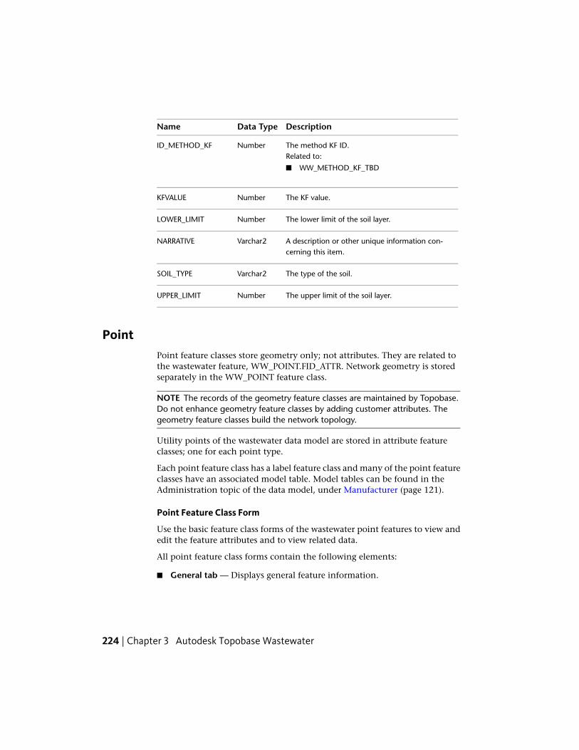
DescriptionData TypeName
The method KF ID.NumberID_METHOD_KFRelated to:
■ WW_METHOD_KF_TBD
The KF value.NumberKFVALUE
The lower limit of the soil layer.NumberLOWER_LIMIT
A description or other unique information con-cerning this item.
Varchar2NARRATIVE
The type of the soil.Varchar2SOIL_TYPE
The upper limit of the soil layer.NumberUPPER_LIMIT
PointPoint feature classes store geometry only; not attributes. They are related tothe wastewater feature, WW_POINT.FID_ATTR. Network geometry is storedseparately in the WW_POINT feature class.
NOTE The records of the geometry feature classes are maintained by Topobase.Do not enhance geometry feature classes by adding customer attributes. Thegeometry feature classes build the network topology.
Utility points of the wastewater data model are stored in attribute featureclasses; one for each point type.
Each point feature class has a label feature class and many of the point featureclasses have an associated model table. Model tables can be found in theAdministration topic of the data model, under Manufacturer (page 121).
Point Feature Class Form
Use the basic feature class forms of the wastewater point features to view andedit the feature attributes and to view related data.
All point feature class forms contain the following elements:
■ General tab — Displays general feature information.
224 | Chapter 3 Autodesk Topobase Wastewater

■ Details tab — Displays detailed feature attributes and link buttons thatprovide links to all line features (sections) the points are connected to.
■ Related Tables tab — Allows direct access to the following related tables:
Table Name and DescriptionRelated Table
WW_MAINTENANCE. Contains information about networkmaintenance.
Maintenance
See Maintenance (page 211).
WW_MARKER. Contains marker information. The marker isplaced above ground to indicate the position of a networkpart.
Marker
See Marker (page 213).
WW_COVER. Contains related cover information.CoverSee Cover (page 231).
■ Table tab — Displays all attributes in table form.
Each point feature class form provides functions for further processing of theselected records. For more information, see Use Wastewater Feature Functions(page 82).
Connecting Point Features to Sites
Each network point can be connected to a site. The easiest way to connect anetwork point to a site is to use the Network Point Creation workflow. Formore information, see Network Point Creation (page 69).
If you have an existing point without a site connection, you can assign it toa site.
To connect a point to a site
1 Click the Document explorer icon.
2 Right-click the feature class, such as Manhole, and click Show Form.
3 Select the manhole to connect to the site.
4 Click the Related Tables tab.
5 Click the Point (WW_POINT) reference button to display the related geometry feature.
Wastewater Feature Classes and Types | 225

6 In the Point feature class form, click the Details tab.
7 Under Site, select the FID of the related site.
8 Click Update (F5).
For more information about sites, see Site (page 320).
Accumulation BasinAn accumulation basin is a low region where water flows. Its main purpose isto decelerate the water flow.
■ Computation table — WW_ACC_BASIN
■ Feature type — Attribute
DescriptionData TypeName
The capacity of the accumulation basin, measuredin cubic meters.
NumberCAPACITY
The depth of the accumulation basin, measuredin meters.
NumberDEPTH
The first dimension of the accumulation basin,measured in meters.
NumberDIMENSION_1
The second dimension of the accumulation basin,measured in meters.
NumberDIMENSION_2
The relation to the environmental parameters.NumberFID_ENV_PARAMET-ERS Related to:
■ WW_ENV_PARAMETERS
The location of the item (street).Related to:
NumberFID_LOCATION
■ WW_LOCATION
Relation with the site.NumberFID_SITERelated to:
■ WW_SITE
226 | Chapter 3 Autodesk Topobase Wastewater

DescriptionData TypeName
Type of installation.NumberID_INSTALLA-TION_TYPE Related to:
■ WW_INSTALLATION_TYPE_TBD
The type of material composition used for theaccumulation basin.
NumberID_MATERIAL
Related to:
■ WW_MATERIAL_TBD
The input elevation, measured in meters.NumberINPUT_ELEVATION
Is a pump present?NumberIS_PUMP
The name or number of this item.Varchar2NAME_NUMBER
The outflow value.NumberOUTFLOW
The output elevation, measured in meters.NumberOUTPUT_ELEVATION
The separation volume, measured in cubicmeters.
NumberSEP_VOLUME
BasinA basin is a region of land or a receptacle into which waste water flows.
■ Computation table — WW_BASIN
■ Feature type — Attribute
DescriptionData TypeName
The basin manufacturer’s address.Varchar2ADDRESSOFMANU-FACTURER
The capacity of the basin, measured in cubicmeters.
NumberCAPACITY
Wastewater Feature Classes and Types | 227

DescriptionData TypeName
The date when the item was created.DateDATE_CREATION
The relation to the environmental parameters.NumberFID_ENV_PARAMET-ERS Related to:
■ WW_ENV_PARAMETERS
The location of the item (street).Related to:
NumberFID_LOCATION
■ WW_LOCATION
The basin filter layer.NumberFILTERLAYER
The basin foot print.NumberFOOTPRINT
The arrangement of the basin.NumberID_ARRANGEMENTRelated to:
■ WW_ARRANGEMENT_TBD
The basin design ID.NumberID_BASIN_DESIGNRelated to:
■ WW_BASIN_DESIGN_TBD
The basin function ID.NumberID_BASIN_FUNC-TION Related to:
■ WW_BASIN_FUNCTION_TBD
The basin shape ID.NumberID_BASIN_SHAPERelated to:
■ WW_BASIN_SHAPE_TBD
The basin type ID.NumberID_BASIN_TYPERelated to:
■ WW_BASIN_TYPE_TBD
The basin version ID.NumberID_BASIN_VERSIONRelated to:
228 | Chapter 3 Autodesk Topobase Wastewater

DescriptionData TypeName
■ WW_BASIN_VERSION_TBD
The state of the disposition of the item. For ex-ample, death, planed, etc.
NumberID_DISPOSI-TION_STATE
Related to:
■ WW_DISPOSITION_STATE_TBD
The filter material ID.NumberID_FILTER_MATERIALRelated to:
■ WW_FILTER_MATERIAL_TBD
The hydraulic function of the item.NumberID_HYDRAUL-IC_FUNCTION Related to:
■ WW_HYDRAULIC_FUNCTION_TBD
The planting ID.NumberID_PLANTINGRelated to:
■ WW_PLANTING_TBD
Is there a handover?NumberIS_HANDOVER
The LISA unique identifier.Varchar2LISA_GUID
A description of the manufacturer type.Varchar2MANUFAC-TURER_TYPE
The name or number of this item.Varchar2NAME_NUMBER
Additional name number of the item.Varchar2NAME_NUMBER_1
A description or other unique information con-cerning the subject item.
Varchar2NARRATIVE
The number of chambers.NumberNUMBEROFCHAM-BERS
The number of inlets.NumberNUMBEROFINLETS
Wastewater Feature Classes and Types | 229

DescriptionData TypeName
The number of outlets.NumberNUMBEROFOUTLETS
The unique sequence identifier.NumberSEQUENCEID
The site depth, measured in meters.NumberSITE_DEPTH
The site length, measured in meters.NumberSITE_LENGTH
The site width, measured in meters.NumberSITE_WIDTH
The slope inclination.NumberSLOPEINCLINATION
The space above ground, measured in meters.NumberSPACE_ABOVE_GROUND
The space below ground, measured in meters.NumberSPACE_BE-LOW_GROUND
The UFIS construction number.NumberUFIS_CONSTRUC-TIONNUMBER
Coalescence SeparatorA coalescence separator is the part of a site where large wastewater particules,like oil and water, get separated.
■ Computation table — WW_COALESCENCE_SEP
■ Feature type — Attribute
DescriptionData TypeName
The depth of the coalescence separator, measuredin meters.
NumberDEPTH
The first dimension of the coalescence separator,measured in meters.
NumberDIMENSION_1
The second dimension of the coalescence separ-ator, measured in meters.
NumberDIMENSION_2
230 | Chapter 3 Autodesk Topobase Wastewater

DescriptionData TypeName
The relation to the environmental parameters.NumberFID_ENV_PARAMET-ERS Related to:
■ WW_ENV_PARAMETERS
The location of the item (street).Related to:
NumberFID_LOCATION
■ WW_LOCATION
Relation with the site.NumberFID_SITERelated to:
■ WW_SITE
Type of installation.NumberID_INSTALLA-TION_TYPE Related to:
■ WW_INSTALLATION_TYPE_TBD
The type of material composition used for thecoalescence separator.
NumberID_MATERIAL
Related to:
■ WW_MATERIAL_TBD
The input elevation, measured in meters.NumberINPUT_ELEVATION
The name or number of this item.Varchar2NAME_NUMBER
The output elevation, measured in meters.NumberOUTPUT_ELEVATION
CoverThe cover feature clases stores cover information for network points, such asa manhole.
Covers are stored in a separate point feature class that is not part of the networktopology.
■ Computation table — WW_COVER
Wastewater Feature Classes and Types | 231

■ Feature type — Point
DescriptionData TypeName
The first dimension of the cover, measured inmeters.
NumberDIMENSION_1
The second dimension of the cover, measured inmeters.
NumberDIMENSION_2
The concessionaire of this item.NumberFID_CONSESSION-AIRE Related to:
■ WW_CONTACT
The connection with the first manhole.Related to:
NumberFID_FEATURE_1
■ WW_DISCHARGE
■ WW_DISPOSAL_TANK
■ WW_GREASE_TRAP
■ WW_GRIT_CHAMBER
■ WW_MANHOLE
■ WW_NEUTRALIZER
■ WW_OIL_WATER_SEP
■ WW_OUTFALL
■ WW_SEPTIC_TANK
■ WW_FRENCH_DRAINS
■ WW_SITE
The connection with the first manhole.Related to:
NumberFID_FEATURE_2
■ WW_DISCHARGE
■ WW_DISPOSAL_TANK
■ WW_GREASE_TRAP
■ WW_GRIT_CHAMBER
■ WW_MANHOLE
■ WW_NEUTRALIZER
232 | Chapter 3 Autodesk Topobase Wastewater

DescriptionData TypeName
■ WW_OIL_WATER_SEP
■ WW_OUTFALL
■ WW_SEPTIC_TANK
■ WW_FRENCH_DRAINS
■ WW_SITE
The enterprise in charge of building the item.NumberFID_INSTALLERRelated to:
■ WW_CONTACT
The company that is responsible for the mainten-ance of this item.
NumberFID_MAINTENANCE
Related to:
■ WW_CONTACT
The manufacturer of this item.NumberFID_MANUFAC-TURER Related to:
■ WW_CONTACT
The operator of this itemNumberFID_OPERATORRelated to:
■ WW_CONTACT
The owner of this itemNumberFID_OWNERRelated to:
■ WW_CONTACT
The height of the support rings, measured inmeters.
NumberHEIGHT_SUP-PORT_RINGS
How the current position of the item was determ-ined. For example, exactly, by positioning, un-known, or inexactly.
NumberID_ACCURACY
Related to:
■ WW_ACCURACY_TBD
Wastewater Feature Classes and Types | 233

DescriptionData TypeName
Defines the aeration type of the cover.NumberID_AERATIONRelated to:
■ WW_COVER_AER_TBD
The cover shape.NumberID_COVER_SHAPERelated to:
■ WW_COVER_SHAPE_TBD
The cover type.NumberID_COVER_TYPERelated to:
■ WW_COVER_TYPE_TBD
The accuracy of the elevation.NumberID_HEIGHT_ACCUR-ACY Related to:
■ WW_HEIGHT_ACCURACY_TBD
The load class.NumberID_LOAD_CLASSRelated to:
■ WW_COVER_LOAD_TBD
Defines if a lock exists on the cover.NumberID_LOCKRelated to:
■ WW_COVER_LOCK_TBD
The material of this item.NumberID_MATERIALRelated to:
■ WW_COVER_MAT_TBD
Is there a dirt trap?NumberIS_DIRTTRAP
The maximum load accepted by the cover.NumberLOAD_LIMIT
The name or number of this item.Varchar2NAME_NUMBER
A description or other unique information con-cerning the subject item.
Varchar2NARRATIVE
234 | Chapter 3 Autodesk Topobase Wastewater

DescriptionData TypeName
The number of support rings.NumberNUMBER_SUP-PORT_RINGS
An operator defined work area. This attribute canbe used by the operator for user defined system
Varchar2USER_FLAG
processes. It does not effect the subject item'sdata integrity and should not be used to storethe subject item's data.
The cover height value.NumberZ
NOTE You must enable the automatic update of the cover Z in the wastewaterdocument options. See Set Wastewater Document Options (page 333).
When you create a cover that is related to a manhole, or when you connecta cover to a manhole, the cover height Z will not be calculated automatically.Existing values of Z, DEPTH, or BOTTOM_ELEVATION are not changed. Onlywhen you update either Z, DEPTH, or BOTTOM_ELEVATION, the values areupdated.
Use the Manhole Creation workflow to create a related cover. For moreinformation, see the following topics:
■ Manhole Creation (page 69)
■ Connect a Point to a Cover (page 85)
■ Cover Creation (page 85)
■ Wastewater Elevation, Slope, and Height (page 335)
DischargeA discharge is the location where wastewater pipes directly discharge effluent.
■ Computation table — WW_DISCHARGE
Wastewater Feature Classes and Types | 235

■ Feature type — Attribute
DescriptionData TypeName
The discharge manufacturer’s address.Varchar2ADDRESSOFMANU-FACTURER
The elevation of the bottom part of the item rel-ative to the section.
NumberBOTTOM_ELEVA-TION
The date when the item was created.DateDATE_CREATION
The concessionaire of this item.NumberFID_CONSESSION-AIRE Related to:
■ WW_CONTACT
The environmental parameters.Related to:
NumberFID_ENV_PARAMET-ERS
■ WW_ENV_PARAMETERS
The enterprise in charge of building the item.NumberFID_INSTALLERRelated to:
■ WW_CONTACT
The street location of this item.NumberFID_LOCATIONRelated to:
■ WW_CONTACT
The company that is responsible for the mainten-ance of this item.
NumberFID_MAINTENANCE
Related to:
■ WW_CONTACT
The operator of this itemNumberFID_OPERATORRelated to:
■ WW_CONTACT
The owner of this itemNumberFID_OWNER
236 | Chapter 3 Autodesk Topobase Wastewater

DescriptionData TypeName
Related to:
■ WW_CONTACT
The discharge crest.NumberID_DIS-CHARGE_CREST Related to:
■ WW_DISCHARGE_CREST_TBD
Defines the discharge function.NumberID_DIS-CHARGE_FUNCTION Related to:
■ WW_DISCHARGE_FUNCTION_TBD
Defines the type of discharge.NumberID_DISCHARGE_TYPERelated to:
■ WW_DISCHARGE_TYPE_TBD
The state of the disposition of the item. For ex-ample, death, planed, etc.
NumberID_DISPOSI-TION_STATE
Related to:
■ WW_DISPOSITION_STATE_TBD
The hydraulic function of the item.NumberID_HYDRAUL-IC_FUNCTION Related to:
■ WW_HYDRAULIC_FUNCTION_TBD
The owner of this item.NumberID_OWNERSHIPRelated to:
■ WW_OWNERSHIP_TBD
Is there a handover?NumberIS_HANDOVER
The length of the threshold.NumberLENGTH_THRESHOLD
The LISA unique identifier.Varchar2LISA_GUID
The description of the manufacturer type.Varchar2MANUFAC-TURER_TYPE
Wastewater Feature Classes and Types | 237
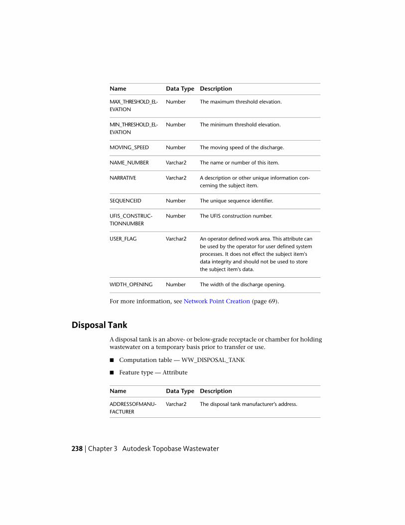
DescriptionData TypeName
The maximum threshold elevation.NumberMAX_THRESHOLD_EL-EVATION
The minimum threshold elevation.NumberMIN_THRESHOLD_EL-EVATION
The moving speed of the discharge.NumberMOVING_SPEED
The name or number of this item.Varchar2NAME_NUMBER
A description or other unique information con-cerning the subject item.
Varchar2NARRATIVE
The unique sequence identifier.NumberSEQUENCEID
The UFIS construction number.NumberUFIS_CONSTRUC-TIONNUMBER
An operator defined work area. This attribute canbe used by the operator for user defined system
Varchar2USER_FLAG
processes. It does not effect the subject item'sdata integrity and should not be used to storethe subject item's data.
The width of the discharge opening.NumberWIDTH_OPENING
For more information, see Network Point Creation (page 69).
Disposal TankA disposal tank is an above- or below-grade receptacle or chamber for holdingwastewater on a temporary basis prior to transfer or use.
■ Computation table — WW_DISPOSAL_TANK
■ Feature type — Attribute
DescriptionData TypeName
The disposal tank manufacturer’s address.Varchar2ADDRESSOFMANU-FACTURER
238 | Chapter 3 Autodesk Topobase Wastewater

DescriptionData TypeName
The area of the disposal tank, measured in squaremeters.
NumberAREA
The elevation of the bottom part of the item rel-ative to the section, measured in meters.
NumberBOTTOM_ELEVA-TION
The capacity of the disposal tank, measured incubic meters.
NumberCAPACITY
The connected area of the disposal tank.NumberCONNECTED_AREA
The date when the item was created.DateDATE_CREATION
The depth of the disposal tank, measured inmeters.
NumberDEPTH
The detention capacity of the disposal tank,measured in cubic meters.
NumberDETENTION_CAPA-CITY
The diameter of the disposal tank, measured inmeters.
NumberDIAMETER
The first dimension of the disposal tank, measuredin meters.
NumberDIMENSION_1
The second dimension of the disposal tank,measured in meters.
NumberDIMENSION_2
The elevation of the disposal tank, measured inmeters.
NumberELEVATION
The concessionaire of this item.NumberFID_CONSESSION-AIRE Related to:
■ WW_CONTACT
The environmental parameters.Related to:
NumberFID_ENV_PARAMET-ERS
■ WW_ENV_PARAMETERS
The enterprise in charge of building the item.NumberFID_INSTALLER
Wastewater Feature Classes and Types | 239

DescriptionData TypeName
Related to:
■ WW_CONTACT
The street location of this item.NumberFID_LOCATIONRelated to:
■ WW_CONTACT
The company that is responsible for the mainten-ance of this item.
NumberFID_MAINTENANCE
Related to:
■ WW_CONTACT
The operator of this itemNumberFID_OPERATORRelated to:
■ WW_CONTACT
The owner of this itemNumberFID_OWNERRelated to:
■ WW_CONTACT
Defines the disposal function.NumberID_DISPOSAL_FUNC-TION Related to:
■ WW_DISPOSAL_FUNCTION_TBD
The state of the disposition of the item. For ex-ample, death, planed, etc.
NumberID_DISPOSI-TION_STATE
Related to:
■ WW_DISPOSITION_STATE_TBD
Defines the filter type.NumberID_FILTER_TYPERelated to:
■ WW_FILTER_TYPE_TBD
The hydraulic function of the item.NumberID_HYDRAUL-IC_FUNCTION Related to:
240 | Chapter 3 Autodesk Topobase Wastewater
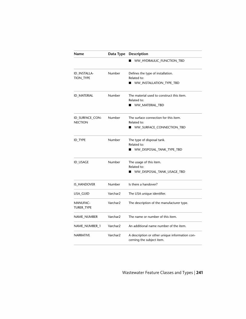
DescriptionData TypeName
■ WW_HYDRAULIC_FUNCTION_TBD
Defines the type of installation.NumberID_INSTALLA-TION_TYPE Related to:
■ WW_INSTALLATION_TYPE_TBD
The material used to construct this item.NumberID_MATERIALRelated to:
■ WW_MATERIAL_TBD
The surface connection for this item.NumberID_SURFACE_CON-NECTION Related to:
■ WW_SURFACE_CONNECTION_TBD
The type of disposal tank.NumberID_TYPERelated to:
■ WW_DISPOSAL_TANK_TYPE_TBD
The usage of this item.NumberID_USAGERelated to:
■ WW_DISPOSAL_TANK_USAGE_TBD
Is there a handover?NumberIS_HANDOVER
The LISA unique identifier.Varchar2LISA_GUID
The description of the manufacturer type.Varchar2MANUFAC-TURER_TYPE
The name or number of this item.Varchar2NAME_NUMBER
An additional name number of the item.Varchar2NAME_NUMBER_1
A description or other unique information con-cerning the subject item.
Varchar2NARRATIVE
Wastewater Feature Classes and Types | 241

DescriptionData TypeName
The normal head dimension, measured in meters.NumberNORMAL_HEAD_DI-MENSION
The normal operating pressure rate.NumberNORMAL_PRESSURE
The overflow elevation, measured in meters.NumberOVERFLOW_ELEVA-TION
The restrictor discharge.NumberRESTRICTOR_DIS-CHARGE
The unique sequence identifier.NumberSEQUENCEID
The UFIS construction number.NumberUFIS_CONSTRUC-TIONNUMBER
An operator defined work area. This attribute canbe used by the operator for user defined system
Varchar2USER_FLAG
processes. It does not effect the subject item'sdata integrity and should not be used to storethe subject item's data.
For more information, see Network Point Creation (page 69).
Emulsion Split■ Computation table — WW_EMULSION_SPLIT
■ Feature type — Attribute
DescriptionData TypeName
The depth of the emulsion split, measured inmeters.
NumberDEPTH
The first dimension of the emulsion split, meas-ured in meters.
NumberDIMENSION_1
The second dimension of the emulsion split,measured in meters.
NumberDIMENSION_2
242 | Chapter 3 Autodesk Topobase Wastewater

DescriptionData TypeName
The relation to the environmental parameters.NumberFID_ENV_PARAMET-ERS Related to:
■ WW_ENV_PARAMETERS
The location of the item (street).Related to:
NumberFID_LOCATION
■ WW_LOCATION
Relation with the site.NumberFID_SITERelated to:
■ WW_SITE
The chemical used to produce flocculation ofsuspended particles.
Varchar2FLOCCULANT
Type of installation.NumberID_INSTALLA-TION_TYPE Related to:
■ WW_INSTALLATION_TYPE_TBD
The type of material composition used for thecoalescence separator.
NumberID_MATERIAL
Related to:
■ WW_MATERIAL_TBD
The input elevation, measured in meters.NumberINPUT_ELEVATION
The name or number of this item.Varchar2NAME_NUMBER
Defines the outflow.NumberOUTFLOW
The output elevation, measured in meters.NumberOUTPUT_ELEVATION
The population equivalents.NumberPOPULATIONEQUI-VALENTS
Wastewater Feature Classes and Types | 243
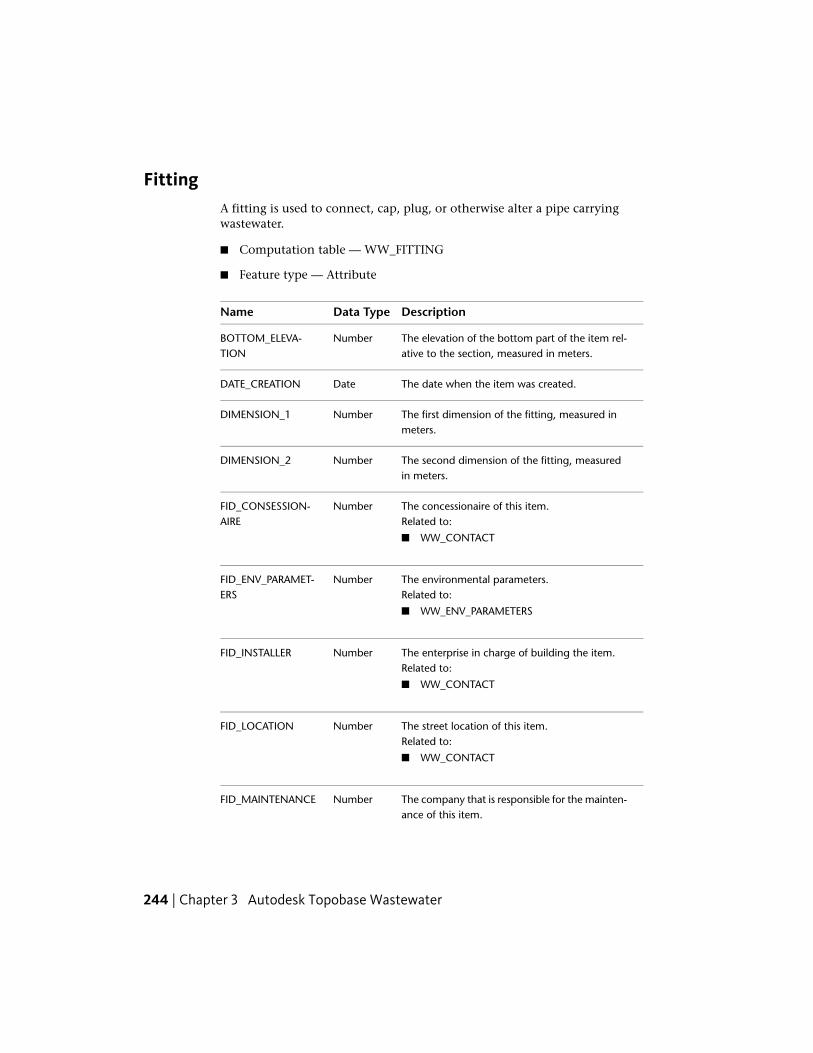
FittingA fitting is used to connect, cap, plug, or otherwise alter a pipe carryingwastewater.
■ Computation table — WW_FITTING
■ Feature type — Attribute
DescriptionData TypeName
The elevation of the bottom part of the item rel-ative to the section, measured in meters.
NumberBOTTOM_ELEVA-TION
The date when the item was created.DateDATE_CREATION
The first dimension of the fitting, measured inmeters.
NumberDIMENSION_1
The second dimension of the fitting, measuredin meters.
NumberDIMENSION_2
The concessionaire of this item.NumberFID_CONSESSION-AIRE Related to:
■ WW_CONTACT
The environmental parameters.Related to:
NumberFID_ENV_PARAMET-ERS
■ WW_ENV_PARAMETERS
The enterprise in charge of building the item.NumberFID_INSTALLERRelated to:
■ WW_CONTACT
The street location of this item.NumberFID_LOCATIONRelated to:
■ WW_CONTACT
The company that is responsible for the mainten-ance of this item.
NumberFID_MAINTENANCE
244 | Chapter 3 Autodesk Topobase Wastewater

DescriptionData TypeName
Related to:
■ WW_CONTACT
The operator of this itemNumberFID_OPERATORRelated to:
■ WW_CONTACT
The owner of this itemNumberFID_OWNERRelated to:
■ WW_CONTACT
How the current position of the item was determ-ined. For example, exactly, by positioning, un-known, or inexactly.
NumberID_ACCURACY
Related to:
■ WW_ACCURACY_TBD
The state of the disposition of the item. For ex-ample, death, planed, etc.
NumberID_DISPOSI-TION_STATE
Related to:
■ WW_DISPOSITION_STATE_TBD
How the item is used.NumberID_FUNCTIONRelated to:
■ WW_FITTING_FUNCTION_TBD
The elevation accuracy.NumberID_HEIGHT_ACCUR-ACY Related to:
■ WW_HEIGHT_ACCURACY_TBD
The hydraulic function of the item.NumberID_HYDRAUL-IC_FUNCTION Related to:
■ WW_HYDRAULIC_FUNCTION_TBD
Wastewater Feature Classes and Types | 245

DescriptionData TypeName
The type of material composition used for thefitting.
NumberID_MATERIAL
Related to:
■ WW_MATERIAL_TBD
The LISA unique identifier.Varchar2LISA_GUID
The name or number of this item.Varchar2NAME_NUMBER
An additional name number of the item.Varchar2NAME_NUMBER_1
A description or other unique information con-cerning the subject item.
Varchar2NARRATIVE
The unique sequence identifier.NumberSEQUENCEID
An operator defined work area. This attribute canbe used by the operator for user defined system
Varchar2USER_FLAG
processes. It does not effect the subject item'sdata integrity and should not be used to storethe subject item's data.
For more information, see Network Point Creation (page 69).
French DrainsA drainage trench filled to ground level with gravel, rock, fragments of brick,etc.
■ Computation table — WW_FRENCH_DRAINS
■ Feature type — Attribute
DescriptionData TypeName
The french drain manufacturer’s address.Varchar2ADDRESSOFMANU-FACTURER
The basin area of the french drain, measured insquare meters.
NumberBASIN_AREA
246 | Chapter 3 Autodesk Topobase Wastewater

DescriptionData TypeName
The permanent basin area of the french drain,measured in square meters.
NumberBASIN_AREA_PER-MANENT
The basin capacity of the french drain, measuredin cubic meters.
NumberBASIN_CAPACITY
The basin depth of the french drain, measuredin meters.
NumberBASIN_DEPTH
The first basin dimension of the french drain,measured in meters.
NumberBASIN_DIMEN-SION_1
The second basin dimension of the french drain,measured in meters.
NumberBASIN_DIMEN-SION_2
The permanent basin height of the french drain,measured in meters.
NumberBASIN_HEIGHT_PER-MANENT
The maximum basin height of the french drain,measured in meters.
NumberBASIN_MAX_HEIGHT
The basin slope of the french drain.NumberBASIN_SLOPE
The basin spillover of the french drain.NumberBASIN_SPILLOVER
The basin baselayer thickness of the french drain.NumberBASIN_THICK-NESS_BASELAYER
Description of cadastral information, such as landboundaries, structure locations, boundary dimen-sions, etc.
Varchar2CADASTRAL_INFO
The date when the item was commissioned.DateDATE_COMMISION-ING
The date when the item was created.DateDATE_CREATION
The first dimension of the item, measured inmeters.
NumberDIMENSION_1
Wastewater Feature Classes and Types | 247

DescriptionData TypeName
The second dimension of the item, measured inmeters.
NumberDIMENSION_2
The capacity of the ditch, measured in cubicmeters.
NumberDITCH_CAPACITY
The ditch capacity coefficient.NumberDITCH_CAPA-CITY_COEFFICIENT
The depth of the ditch, measured in meters.NumberDITCH_DEPTH
The first dimension of the ditch, measured inmeters.
NumberDITCH_DIMEN-SION_1
The number of pipes laid in the ditch.NumberDITCH_NUM-BER_PIPES
The pipe diameter, measured in meters.NumberDITCH_PIPE_DIAMET-ER
The restrictor discharge of the ditch.NumberDITCH_RESTRICT-OR_DISCHARGE
The restrictor manhole of the ditch.Varchar2DITCH_RESTRICT-OR_MANHOLE
The ditch spillover amount.Varchar2DITCH_SPILLOVER
The relation to the environmental parameters.NumberFID_ENV_PARAMET-ERS Related to:
■ WW_ENV_PARAMETERS
The location of the item (street).Related to:
NumberFID_LOCATION
■ WW_LOCATION
The state of the disposition of the item. For ex-ample, death, planed, etc.
NumberID_DISPOSI-TION_STATE
Related to:
■ WW_DISPOSITION_STATE_TBD
248 | Chapter 3 Autodesk Topobase Wastewater

DescriptionData TypeName
The ditch fill material ID.NumberID_DITCH_FILLING_MA-TERIAL Related to:
■ WW_FILLING_MATERIAL_TBD
The ditch restr manhole ID.NumberID_DITCH_RE-STR_MANHOLE Related to:
■ WW_DITCH_RESTR_MANHOLE_TBD
The hydraulic function of the item.NumberID_HYDRAUL-IC_FUNCTION Related to:
■ WW_HYDRAULIC_FUNCTION_TBD
The infiltration system ID.NumberID_INFILTRA-TION_SYSTEM Related to:
■ WW_INFILTRATION_SYSTEM_TBD
The manhole fill material ID.NumberID_MHOLE_FILLING_MA-TERIAL Related to:
■ WW_FILLING_MATERIAL_TBD
The manhole infiltration type ID.NumberID_MHOLE_INF_TYPERelated to:
■ WW_MHOLE_INF_TBD
The pipe material ID.NumberID_PIPE_MATERIALRelated to:
■ WW_MATERIAL_TBD
The surface connection ID.NumberID_SURFACE_CON-NECTION Related to:
■ WW_SURFACE_CONNECTION_TBD
Is there a basin spillover?NumberIS_BASIN_SPILLOVER
Wastewater Feature Classes and Types | 249

DescriptionData TypeName
Is there a ditch spillover?NumberIS_DITCH_SPILLOVER
Is there a handover?NumberIS_HANDOVER
Is there a manhole filter?NumberIS_MHOLE_FILTER
Is there a manhole spillover?NumberIS_MHOLE_SPILLOVER
Is there a surface spillover?NumberIS_SURF_SPILLOVER
The LISA unique identifier.Varchar2LISA_GUID
A description of the manufacturer type.Varchar2MANUFAC-TURER_TYPE
The maximum infiltration of the item.NumberMAX_INFILTRATION
How frequently are measurements taken?NumberMEASUREMENT_FRE-QUENCY
The manhole area, measured in square meters.NumberMHOLE_AREA
The manhole depth, measured in meters.NumberMHOLE_DEPTH
The second manhole dimension, measured inmeters.
NumberMHOLE_DIMEN-SION_2
The manhole height, measured in meters.NumberMHOLE_MAX_HEIGHT
The restrictor discharge of the manhole.NumberMHOLE_RESTRICT-OR_DISCHARGE
The manhole spillover amount.Varchar2MHOLE_SPILLOVER
The manhole storage capcity, measured in cubicmeters.
NumberMHOLE_STORAGE
The name or number of this item.Varchar2NAME_NUMBER
Additional name number of the item.Varchar2NAME_NUMBER_1
250 | Chapter 3 Autodesk Topobase Wastewater

DescriptionData TypeName
A description or other unique information con-cerning the subject item.
Varchar2NARRATIVE
The unique sequence identifier.NumberSEQUENCEID
The first surface dimension, measured in meters.NumberSURF_DIMENSION_1
The second surface dimension, measured inmeters.
NumberSURF_DIMENSION_2
The surface spillover amount.Varchar2SURF_SPILLOVER
The UFIS construction number.NumberUFIS_CONSTRUC-TIONNUMBER
Grease TrapA grease trap is a tank that separates grease from water, collects the grease forremoval, and allows the water to exit.
■ Computation table — WW_GREASE_TRAP
■ Feature type — Attribute
DescriptionData TypeName
The elevation of the bottom part of the item rel-ative to the section, measured in meters.
NumberBOTTOM_ELEVA-TION
The capacity of the grease trap, measured in cu-bic meters.
NumberCAPACITY
The date when the item was created.DateDATE_CREATION
The first dimension of the grease trap, measuredin meters.
NumberDIMENSION_1
The second dimension of the grease trap, meas-ured in meters.
NumberDIMENSION_2
Wastewater Feature Classes and Types | 251

DescriptionData TypeName
The concessionaire of this item.NumberFID_CONSESSION-AIRE Related to:
■ WW_CONTACT
The enterprise in charge of building the item.NumberFID_INSTALLERRelated to:
■ WW_CONTACT
The location of the item (street).Related to:
NumberFID_LOCATION
■ WW_LOCATION
The company that is responsible for the mainten-ance of this item.
NumberFID_MAINTENANCE
Related to:
■ WW_CONTACT
The operator of this itemNumberFID_OPERATORRelated to:
■ WW_CONTACT
The owner of this itemNumberFID_OWNERRelated to:
■ WW_CONTACT
The relation of the item with the site.NumberFID_SITERelated to:
■ WW_SITE
The flow rate.NumberFLOW_RATE
The state of the disposition of the item. For ex-ample, death, planed, etc.
NumberID_DISPOSI-TION_STATE
Related to:
■ WW_DISPOSITION_STATE_TBD
252 | Chapter 3 Autodesk Topobase Wastewater

DescriptionData TypeName
Defines the type of installation.NumberID_INSTALLA-TION_TYPE Related to:
■ WW_INSTALLATION_TYPE_TBD
The material used to construct this item.NumberID_MATERIALRelated to:
■ WW_MATERIAL_TBD
The structural condition of this item.NumberID_STRUCT_CONDI-TION Related to:
■ WW_STRUCT_CONDITION_TBD
The input elevation, measured in meters.NumberINPUT_ELEVATION
The name or number of this item.Varchar2NAME_NUMBER
A description or other unique information con-cerning the subject item.
Varchar2NARRATIVE
The nominal size of the grease trap.NumberNOMINAL_SIZE
The output elevation.NumberOUTPUT_ELEVATION
An operator defined work area. This attribute canbe used by the operator for user defined system
Varchar2USER_FLAG
processes. It does not effect the subject item'sdata integrity and should not be used to storethe subject item's data.
For more information, see Network Point Creation (page 69).
Grit ChamberA grit chamber is a chamber designed to remove sand, gravel, or other heavysolids that have subsiding velocities or specific gravities substantially greaterthan those of the organic solids in the wastewater system.
■ Computation table — WW_GRIT_CHAMBER
Wastewater Feature Classes and Types | 253

■ Feature type — Attribute
DescriptionData TypeName
The elevation of the bottom part of the item rel-ative to the section, measured in meters.
NumberBOTTOM_ELEVA-TION
The capacity of the grit chamber, measured incubic meters.
NumberCAPACITY
The date when the item was created.DateDATE_CREATION
The depth of the grit chamber, measured inmeters.
NumberDEPTH
The first dimension of the grit chamber, measuredin meters.
NumberDIMENSION_1
The second dimension of the grit chamber,measured in meters.
NumberDIMENSION_2
The concessionaire of this item.NumberFID_CONSESSION-AIRE Related to:
■ WW_CONTACT
The relation to the environmental parameters.NumberFID_ENV_PARAMET-ERS Related to:
■ WW_ENV_PARAMETERS
The enterprise in charge of building the item.NumberFID_INSTALLERRelated to:
■ WW_CONTACT
The company that is responsible for the mainten-ance of this item.
NumberFID_MAINTENANCE
Related to:
■ WW_CONTACT
The operator of this itemNumberFID_OPERATORRelated to:
254 | Chapter 3 Autodesk Topobase Wastewater

DescriptionData TypeName
■ WW_CONTACT
The owner of this itemNumberFID_OWNERRelated to:
■ WW_CONTACT
The relation of the item with the site.NumberFID_SITERelated to:
■ WW_SITE
The flow capacity.NumberFLOW_CAPACITY
The state of the disposition of the item. For ex-ample, death, planed, etc.
NumberID_DISPOSI-TION_STATE
Related to:
■ WW_DISPOSITION_STATE_TBD
Defines the type of installation.NumberID_INSTALLA-TION_TYPE Related to:
■ WW_INSTALLATION_TYPE_TBD
The material used to construct this item.NumberID_MATERIALRelated to:
■ WW_MATERIAL_TBD
The input elevation, measured in meters.NumberINPUT_ELEVATION
The name or number of this item.Varchar2NAME_NUMBER
A description or other unique information con-cerning the subject item.
Varchar2NARRATIVE
The nominal size.NumberNOMINAL_SIZE
The output elevation.NumberOUTPUT_ELEVATION
Will the grit chamber also separates oil?NumberSEPARATE_OIL
Wastewater Feature Classes and Types | 255

DescriptionData TypeName
The storage capacity, measured in cubic meters.NumberSTORAGE_CAPACITY
An operator defined work area. This attribute canbe used by the operator for user defined system
Varchar2USER_FLAG
processes. It does not effect the subject item'sdata integrity and should not be used to storethe subject item's data.
For more information, see Network Point Creation (page 69).
House ConnectorA house connector is the point at which a service connects to a house.
■ Computation table — WW_HOUSE_CONNECTOR
■ Feature type — Attribute
DescriptionData TypeName
The elevation of the bottom part of the item rel-ative to the section, measured in meters.
NumberBOTTOM_ELEVA-TION
Description of cadastral information, such as landboundaries, structure locations, boundary dimen-sions, etc.
Varchar2CADASTRAL_INFO
The connection fee for the house connection.NumberCONNECTION_FEE
The acquisition date of the data.DateDATE_ACQUIRED
The date when the item was created.DateDATE_CREATION
The date when responsibility for the item wastaken.
DateDATE_STARTUP
The concessionaire of this item.NumberFID_CONSESSION-AIRE Related to:
■ WW_CONTACT
256 | Chapter 3 Autodesk Topobase Wastewater

DescriptionData TypeName
The enterprise in charge of building the item.NumberFID_INSTALLERRelated to:
■ WW_CONTACT
The location of the item (street).Related to:
NumberFID_LOCATION
■ WW_LOCATION
The company that is responsible for the mainten-ance of this item.
NumberFID_MAINTENANCE
Related to:
■ WW_CONTACT
The operator of this itemNumberFID_OPERATORRelated to:
■ WW_CONTACT
The owner of this itemNumberFID_OWNERRelated to:
■ WW_CONTACT
The house number.Varchar2HOUSE
The house number supplement.Varchar2HOUSE_SUPPLE-MENT
How the current position of the item was determ-ined. For example, exactly, by positioning, un-known, inexactly, etc.
NumberID_ACCURACY
Related to:
■ WW_ACCURACY_TBD
The condition of the item. For example, broken,leaking, etc.
NumberID_CONDITION
Related to:
■ WW_CONDITION_TBD
Wastewater Feature Classes and Types | 257

DescriptionData TypeName
The state of the disposition of the item. For ex-ample, death, planed, etc.
NumberID_DISPOSI-TION_STATE
Related to:
■ WW_DISPOSITION_STATE_TBD
The owner of this item.NumberID_OWNERSHIPRelated to:
■ WW_OWNERSHIP_TBD
The type of pre-treatment made before the houseconnection.
NumberID_PRE_TREATMENT
Related to:
■ WW_PRE_TREATMENT_TBD
The juristic name or number (construction num-ber).
Varchar2JURIST-IC_NAME_NUMBER
A brief description of where the item is located.For example, 1m of the wall.
Varchar2LOCATION
The name or number of this item.Varchar2NAME_NUMBER
A description or other unique information con-cerning the subject item.
Varchar2NARRATIVE
The power of the pump used at the house con-nection.
NumberPUMP_POWER
The retention capacity for the house connectionmeasured in cubic meters.
NumberRETENSION_CAPA-CITY
The meter-reading route/area for the house con-nection meter.
Varchar2ROUTE_NUMBER
An operator defined work area. This attribute canbe used by the operator for user defined system
Varchar2USER_FLAG
processes. It does not effect the subject item'sdata integrity and should not be used to storethe subject item's data.
258 | Chapter 3 Autodesk Topobase Wastewater

For more information, see Network Point Creation (page 69).
Manage Customer Information
The WW_HOUSE_CONNECTOR table has a Customer Number attribute.However, there is no table for managing customer information becausecustomers often use external software (for example, SAP) for this purpose.
To manage customer information in Topobase, use the Data ModelAdministrator to create the appropriate feature classes.
To manage customer information
1 Create a new Customer feature class in the Administration topic.
2 Add attributes as needed, for example Name, Address, Telephone, andEmail.
3 Customize the feature class form using the Form Designer.
4 In the House Connector form, add a Basic ComboBox control forCustomer Number and create the relation to the newly created tablecontaining the customers.
For more information, see the Form Designer Introductionin the TopobaseAdministrator Guide.
Generate Customer Notifications
Topobase Wastewater helps you generate notification letters regarding plannedwork or problems in the wastewater network. For example, you might do anetwork trace to find all house connectors in an affected area so you can notifycustomers.
There are three ways to generate customer notification letters.
■ Use the Topobase Report Designer.For more information about the Topobase report designer, see the ReportDesigner Introduction in the Topobase Administrator Guide.
■ Use Topobase Client to export to Microsoft® Word.
■ Export the data to any format and use external software to generate letters.For example, export a customer list to Microsoft® Excel®.
Wastewater Feature Classes and Types | 259

Intermediate PointIntermediate points of a section are the points where pipes meet the structureof a manhole.
■ Computation table — WW_INTERMEDIATE_POINT
■ Feature type — Attribute
DescriptionData TypeName
The elevation of the bottom part of the item rel-ative to the section, measured in meters.
NumberBOTTOM_ELEVA-TION
The date when the item was created.DateDATE_CREATION
The name or number of this item.Varchar2NAME_NUMBER
A description or other unique information con-cerning the subject item.
Varchar2NARRATIVE
An operator defined work area. This attribute canbe used by the operator for user defined system
Varchar2USER_FLAG
processes. It does not effect the subject item'sdata integrity and should not be used to storethe subject item's data.
For more information, see Network Point Creation (page 69).
Intermediate points can be created automatically in the Section Creationworkflow.
260 | Chapter 3 Autodesk Topobase Wastewater

For complex manholes, the intermediate point is the intersection betweenthe section and the polygon detail. For standard manholes the intermediatepoint is calculated from the diameter (stored in theWW_MANHOLE_MODEL.diameter1).
For more information, see Section Creation (page 70) and WastewaterElevation, Slope, and Height (page 335).
LagoonA shallow, man-made pool or pond for the purpose of providing treatmentof domestic wastewater.
■ Computation table — WW_LAGOON
■ Feature type — Attribute
DescriptionData TypeName
Will the lagoon also have an aerator?NumberAERATOR
The power of the aerator.NumberAERATOR_POWER
The area of the lagoon, measured in squaremeters.
NumberAREA
The elevation of the bottom part of the item rel-ative to the section, measured in meters.
NumberBOTTOM_ELEVA-TION
Wastewater Feature Classes and Types | 261

DescriptionData TypeName
The analysis date.DateDATE_ANALYSIS
The date when construction on the item begins.DateDATE_CONSTRUC-TION
The date when the item was created.DateDATE_CREATION
The first dimension of the lagoon, measured inmeters.
NumberDIMENSION_1
The second dimension of the lagoon, measuredin meters.
NumberDIMENSION_2
The concessionaire of this item.NumberFID_CONSESSION-AIRE Related to:
■ WW_CONTACT
The enterprise in charge of building the item.NumberFID_INSTALLERRelated to:
■ WW_CONTACT
The company that is responsible for the mainten-ance of this item.
NumberFID_MAINTENANCE
Related to:
■ WW_CONTACT
The operator of this itemNumberFID_OPERATORRelated to:
■ WW_CONTACT
The owner of this itemNumberFID_OWNERRelated to:
■ WW_CONTACT
Describes the type of lagoon.NumberID_LAGOON_TYPERelated to:
■ WW_LAGOON_TYPE_TBD
262 | Chapter 3 Autodesk Topobase Wastewater

DescriptionData TypeName
The sewage test ID.NumberID_SEWAGE_TESTRelated to:
■ WW_SEWAGE_TEST_TBD
The soil condition ID.NumberID_SOIL_CONDI-TION Related to:
■ WW_SOIL_CONDITION_TBD
The soil erosion ID.NumberID_SOIL_EROSION_COEF-FICIENT Related to:
■ WW_SOIL_EROSION_COEFF_TBD
The soil family ID.NumberID_SOIL_FAMILYRelated to:
■ WW_SOIL_FAMILY_TBD
The soil texture ID.NumberID_SOIL_TEXTURERelated to:
■ WW_SOIL_TEXTURE_TBD
The name or number of this item.Varchar2NAME_NUMBER
A description or other unique information con-cerning the subject item.
Varchar2NARRATIVE
The number of pumps.NumberNR_PUMPS
An operator defined work area. This attribute canbe used by the operator for user defined system
Varchar2USER_FLAG
processes. It does not effect the subject item'sdata integrity and should not be used to storethe subject item's data.
For more information, see Network Point Creation (page 69).
Wastewater Feature Classes and Types | 263
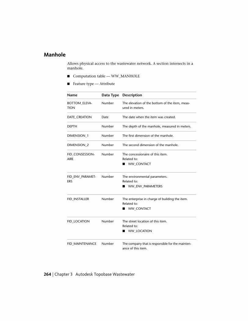
ManholeAllows physical access to the wastewater network. A section intersects in amanhole.
■ Computation table — WW_MANHOLE
■ Feature type — Attribute
DescriptionData TypeName
The elevation of the bottom of the item, meas-ured in meters.
NumberBOTTOM_ELEVA-TION
The date when the item was created.DateDATE_CREATION
The depth of the manhole, measured in meters.NumberDEPTH
The first dimension of the manhole.NumberDIMENSION_1
The second dimension of the manhole.NumberDIMENSION_2
The concessionaire of this item.NumberFID_CONSESSION-AIRE Related to:
■ WW_CONTACT
The environmental parameters.Related to:
NumberFID_ENV_PARAMET-ERS
■ WW_ENV_PARAMETERS
The enterprise in charge of building the item.NumberFID_INSTALLERRelated to:
■ WW_CONTACT
The street location of this item.NumberFID_LOCATIONRelated to:
■ WW_LOCATION
The company that is responsible for the mainten-ance of this item.
NumberFID_MAINTENANCE
264 | Chapter 3 Autodesk Topobase Wastewater

DescriptionData TypeName
Related to:
■ WW_CONTACT
The manufacturer of this item.NumberFID_MANUFAC-TURER Related to:
■ WW_MANUFACTURER
The operator of this itemNumberFID_OPERATORRelated to:
■ WW_CONTACT
The owner of this itemNumberFID_OWNERRelated to:
■ WW_CONTACT
The treament plant related to this itemNumberFID_TREAT-MENT_PLANT Related to:
■ WW_TREATMENT_PLANT
The access aid ID.NumberID_ACCESS_AIDRelated to:
■ WW_MHOLE_ACCESS_AID_TBD
The accessibilty ID.NumberID_ACCESSIBILITYRelated to:
■ WW_MHOLE_ACCESSIBILITY_TBD
How the current position of the item was determ-ined. For example, exactly, by positioning, un-known, inexactly, etc.
NumberID_ACCURACY
Related to:
■ WW_ACCURACY_TBD
The accuracy of the bottom elevation.NumberID_BOTTOM_ACCUR-ACY Related to:
Wastewater Feature Classes and Types | 265

DescriptionData TypeName
■ WW_ACCURACY_TBD
The channel shape ID.NumberID_CHANNEL_SHAPERelated to:
■ WW_CHANNEL_SHAPE_TBD
The inside coating used for the manhole.NumberID_COATING_INSIDERelated to:
■ WW_COATING_TBD
The type of material used to coat the manhole.NumberID_COATING_MA-TERIAL Related to:
■ WW_MATERIAL_TBD
The outside coating used for the manhole.NumberID_COATING_OUT-SIDE Related to:
■ WW_COATING_TBD
The data origination ID.NumberID_DATA_ORIGINRelated to:
■ WW_DATA_ORIGIN_TBD
The state of the disposition of the item. For ex-ample, death, planed, etc.
NumberID_DISPOSI-TION_STATE
Related to:
■ WW_DISPOSITION_STATE_TBD
Defines whether the section is in a floodplain.NumberID_FLOODPLAINRelated to:
■ WW_FLOODPLAIN_TBD
The function ID.NumberID_FUNCTIONRelated to:
■ WW_MHOLE_FUNCTION_TBD
266 | Chapter 3 Autodesk Topobase Wastewater

DescriptionData TypeName
Define whether ground water is present aroundthe section.
NumberID_GROUNDWATER
Related to:
■ WW_GROUNDWATER_TBD
The accuracy of the manhole height.NumberID_HEIGHT_ACCUR-ACY Related to:
■ WW_HEIGHT_ACCURACY_TBD
The hydraulic function of the item.NumberID_HYDRAUL-IC_FUNCTION Related to:
■ WW_HYDRAULIC_FUNCTION_TBD
Describes how the item is placed at its location.NumberID_LAYING_TYPERelated to:
■ WW_MHOLE_LAYING_TYPE_TBD
The lining ID.NumberID_LININGRelated to:
■ WW_LINING_TBD
The lower material ID.NumberID_LOWER_MATERI-AL Related to:
■ WW_MATERIAL_TBD
The shape of the manhole.NumberID_MAN-HOLE_SHAPE Related to:
■ WW_MHOLE_SHAPE_TBD
The manhole type.NumberID_MANHOLE_TYPERelated to:
■ WW_MHOLE_TYPE_TBD
The material used for constructing this item.NumberID_MATERIALRelated to:
Wastewater Feature Classes and Types | 267

DescriptionData TypeName
■ WW_MATERIAL_TBD
The material channel ID.NumberID_MATERIAL_CHAN-NEL Related to:
■ WW_MATERIAL_TBD
The material entry aid ID.NumberID_MATERI-AL_ENTRYAID Related to:
■ WW_MHOLE_ACCESS_AID_TBD
The material lower part ID.NumberID_MATERI-AL_LOWER_PART Related to:
■ WW_MATERIAL_TBD
The manhole lower part shape ID.NumberID_MHOLE_LOWER_PART_SHAPERelated to:
■ WW_MHOLE_LOWER_SHAPE_TBD
The manhole lower shape ID.NumberID_MHOLE_LOWER_SHAPERelated to:
■ WW_MHOLE_LOWER_SHAPE_TBD
The owner of this item.NumberID_OWNERSHIPRelated to:
■ WW_OWNERSHIP_TBD
The state of the traffic on the manhole.NumberID_TRAFFIC_STATERelated to:
■ WW_MHOLE_TRAFFIC_STATE_TBD
The utilization of the manhole.NumberID_UTILISATIONRelated to:
■ WW_MHOLE_UTILISATION_TBD
268 | Chapter 3 Autodesk Topobase Wastewater

DescriptionData TypeName
The water protection ID.NumberID_WATER_PROTEC-TION Related to:
■ WW_WATER_PROTECTION_TBD
Is there a cone?NumberIS_CONE
Is there a cover plate?NumberIS_COVERPLATE
Is there an entry aid?NumberIS_ENTRYAID
Is there a lower part of the cone?NumberIS_LOWER_PART_CONE
Is there a measurement?NumberIS_MEASUREMENT
Is there a pedestal?NumberIS_PEDESTAL
Is there a transfer manhole?NumberIS_TRANSFER_MAN-HOLE
Is there a transition plate?NumberIS_TRANS-ITION_PLATE
The LISA unique identifier.Varchar2LISA_GUID
The lower height of the item, measured in meters.Varchar2LOWERHEIGHT
The lower length of the item, measured in meters.NumberLOWERLENGTH
The height of the lower part, measured in meters.NumberLOWERPARTHEIGHT
The length of the lower part, measured in meters.NumberLOWERPARTLENGTH
The width of the lower part, measured in meters.NumberLOWERPARTWIDTH
The width of the item, measured in meters.NumberLOWERWIDTH
The name or number of this item.Varchar2NAME_NUMBER
The additional name number of the item.Varchar2NAME_NUMBER_1
Wastewater Feature Classes and Types | 269

DescriptionData TypeName
A description or other unique information con-cerning the subject item.
Varchar2NARRATIVE
The number of inputs to the manhole.NumberNR_INPUT_SECTION
The number of outputs from the manhole.NumberNR_OUTPUT_SEC-TION
The number of step irons in the manhole.NumberNR_STEP_IRON
The unique sequence identifier.NumberSEQUENCEID
An operator defined work area. This attribute canbe used by the operator for user defined system
Varchar2USER_FLAG
processes. It does not effect the subject item'sdata integrity and should not be used to storethe subject item's data.
270 | Chapter 3 Autodesk Topobase Wastewater

The cover height is stored in the attribute WW_COVER.Z, the terrain elevationof the manhole is stored in WW_POINT.Z. The soil elevation of the manholeis stored in BOTTOM_ELEVATION. The difference between soil elevation andterrain elevation is the depth.
See also:
■ Manhole Creation (page 69)
■ Network Point Creation (page 69)
■ Wastewater Elevation, Slope, and Height (page 335)
■ Extract Points from Lines (page 95)
■ Feature Rules: Manhole (page 328)
MeterA device installed in a line for measuring the quantity and/or rate of waterthrough a section of line.
■ Computation table — WW_METER
■ Feature type — Attribute
DescriptionData TypeName
The elevation of the bottom of the item, meas-ured in meters.
NumberBOTTOM_ELEVA-TION
The date when the item was created.DateDATE_CREATION
The first dimension of the meter.NumberDIMENSION_1
The second dimension of the meter.NumberDIMENSION_2
The concessionaire of this item.NumberFID_CONSESSION-AIRE Related to:
■ WW_CONTACT
The enterprise in charge of building the item.NumberFID_INSTALLERRelated to:
Wastewater Feature Classes and Types | 271

DescriptionData TypeName
■ WW_CONTACT
The company that is responsible for the mainten-ance of this item.
NumberFID_MAINTENANCE
Related to:
■ WW_CONTACT
The manufacturer of this item.NumberFID_MANUFAC-TURER Related to:
■ WW_MANUFACTURER
The operator of this item.NumberFID_OPERATORRelated to:
■ WW_CONTACT
The owner of this item.NumberFID_OWNERRelated to:
■ WW_CONTACT
The type of meter.NumberID_METER_TYPERelated to:
■ WW_METER_TYPE_TBD
The name or number of this item.Varchar2NAME_NUMBER
A description or other unique information con-cerning the subject item.
Varchar2NARRATIVE
An operator defined work area. This attribute canbe used by the operator for user defined system
Varchar2USER_FLAG
processes. It does not effect the subject item'sdata integrity and should not be used to storethe subject item's data.
For more information, see Network Point Creation (page 69).
272 | Chapter 3 Autodesk Topobase Wastewater

Miscellaneous Plant■ Computation table — WW_MISC_PLANT
■ Feature type — Attribute
DescriptionData TypeName
The depth of the item, measured in meters.NumberDEPTH
The first dimension of the item.NumberDIMENSION_1
The second dimension of the item.NumberDIMENSION_2
The environmental parameters.Related to:
NumberFID_ENV_PARAMET-ERS
■ WW_ENV_PARAMETERS
The street location of this item.NumberFID_LOCATIONRelated to:
■ WW_LOCATION
The relation to the site.NumberFID_SITERelated to:
■ WW_SITE
The type of installation.NumberID_INSTALLA-TION_TYPE Related to:
■ WW_INSTALLATION_TYPE_TBD
The material used to construct this item.NumberID_MATERIALRelated to:
■ WW_MATERIAL_TBD
The elevation of the input, measured in meters.NumberINPUT_ELEVATION
The name or number of this item.Varchar2NAME_NUMBER
The elevation of the output, measured in meters.NumberOUTPUT_ELEVATION
Wastewater Feature Classes and Types | 273

For more information, see Network Point Creation (page 69).
NeutralizerA receptacle or chamber where chemicals react with reactant materials. Thechemically neutralized liquid waste then passes through the wastewater system.
■ Computation table — WW_NEUTRALIZER
■ Feature type — Attribute
DescriptionData TypeName
The elevation of the bottom of the neutralizer,measured in meters.
NumberBOTTOM_ELEVA-TION
The capacity of the neutralizer, measured in cubicmeters.
NumberCAPACITY
The date when the item was created.DateDATE_CREATION
The depth of the neutralizer, measured in meters.NumberDEPTH
The first dimension of the neutralizer, measuredin meters.
NumberDIMENSION_1
The second dimension of the neutralizer, meas-ured in meters.
NumberDIMENSION_2
The concessionaire of this item.NumberFID_CONSESSION-AIRE Related to:
■ WW_CONTACT
The environmental parameters.Related to:
NumberFID_ENV_PARAMET-ERS
■ WW_ENV_PARAMETERS
The enterprise in charge of building the item.NumberFID_INSTALLERRelated to:
■ WW_CONTACT
274 | Chapter 3 Autodesk Topobase Wastewater

DescriptionData TypeName
The street location of this item.NumberFID_LOCATIONRelated to:
■ WW_LOCATION
The company that is responsible for the mainten-ance of this item.
NumberFID_MAINTENANCE
Related to:
■ WW_CONTACT
The operator of this item.NumberFID_OPERATORRelated to:
■ WW_CONTACT
The owner of this item.NumberFID_OWNERRelated to:
■ WW_CONTACT
The relation with the site.NumberFID_SITERelated to:
■ WW_SITE
The state of the disposition of the item. For ex-ample, death, planed, etc.
NumberID_DISPOSI-TION_STATE
Related to:
■ WW_DISPOSITION_STATE_TBD
The type of installation.NumberID_INSTALLA-TION_TYPE Related to:
■ WW_INSTALLATION_TYPE_TBD
The material used for constructing this item.NumberID_MATERIALRelated to:
■ WW_MATERIAL_TBD
Wastewater Feature Classes and Types | 275

DescriptionData TypeName
The neutralization agent ID.NumberID_NEUTRALIZA-TION_AGENT Related to:
■ WW_NEUTRALIZATION_AGENT_TBD
The type of neutralizer.NumberID_TYPE_NEUTRAL-IZER Related to:
■ WW_NEUTRALIZER_TYPE_TBD
The elevation of the input, measured in meters.NumberINPUT_ELEVATION
The name or number of this item.Varchar2NAME_NUMBER
A description or other unique information con-cerning the subject item.
Varchar2NARRATIVE
The name of the neutralizing agent.Varchar2NEUTRAL-IZER_AGENT
The number of pipes.NumberNR_PIPES
The neutralizer outflow.NumberOUTFLOW
The elevation of the output, measured in meters.NumberOUTPOUT_ELEVA-TION
The Ph value.NumberPHVALUE
The amount of reactant, measured in cubicmeters.
NumberREACTANT_QUANT-ITY
An operator defined work area. This attribute canbe used by the operator for user defined system
Varchar2USER_FLAG
processes. It does not effect the subject item'sdata integrity and should not be used to storethe subject item's data.
For more information, see Network Point Creation (page 69).
276 | Chapter 3 Autodesk Topobase Wastewater

Oil Water SeparatorA device or structure placed in the wastewater stream to separate water fromoil products.
■ Computation table — WW_OIL_WATER_SEP
■ Feature type — Attribute
DescriptionData TypeName
Comments about alaram system.Varchar2ALARMSYSTEMCOM-MENTS
The area of the item, measured in square meters.NumberAREA
The elevation of the bottom of the section,measured in meters.
NumberBOTTOM_ELEVA-TION
The capacity of the item, measured in cubicmeters.
NumberCAPACITY
The date when the item was created.DateDATE_CREATION
The depth of the item, measured in meters.NumberDEPTH
The first dimension of the separator, measuredin meters.
NumberDIMENSION_1
The second dimension of the separator, measuredin meters.
NumberDIMENSION_2
The concessionaire of this item.NumberFID_CONSESSION-AIRE Related to:
■ WW_CONTACT
The environmental parameters.Related to:
NumberFID_ENV_PARAMET-ERS
■ WW_ENV_PARAMETERS
The enterprise in charge of building the item.NumberFID_INSTALLERRelated to:
Wastewater Feature Classes and Types | 277

DescriptionData TypeName
■ WW_CONTACT
The street location of this item.NumberFID_LOCATIONRelated to:
■ WW_LOCATION
The company that is responsible for the mainten-ance of this item.
NumberFID_MAINTENANCE
Related to:
■ WW_CONTACT
The operator of this item.NumberFID_OPERATORRelated to:
■ WW_CONTACT
The owner of this item.NumberFID_OWNERRelated to:
■ WW_CONTACT
The relation with the site.NumberFID_SITERelated to:
■ WW_SITE
The alarm system ID.NumberID_ALARM_SYSTEMRelated to:
■ WW_ALARM_SYSTEM_TBD
The state of the disposition of the item. For ex-ample, death, planed, etc.
NumberID_DISPOSI-TION_STATE
Related to:
■ WW_DISPOSITION_STATE_TBD
The type of installation.NumberID_INSTALLA-TION_TYPE Related to:
■ WW_INSTALLATION_TYPE_TBD
278 | Chapter 3 Autodesk Topobase Wastewater

DescriptionData TypeName
The material used for constructing this item.NumberID_MATERIALRelated to:
■ WW_SEPARATOR_MAT_TBD
The type of separator.NumberID_SEPARATOR_TYPERelated to:
■ WW_SEPARATOR_TYPE_TBD
The elevation of the input, measured in meters.NumberINPUT_ELEVATION
The elevation of the first input, measured inmeters.
NumberINPUT_ELEVATION_1
The elevation of the second input, measured inmeters.
NumberINPUT_ELEVATION_2
Is there a close off?NumberIS_CLOSEOFF
The thickness of the layer.NumberLAYERTHICKNESS
The name or number of this item.Varchar2NAME_NUMBER
A description or other unique information con-cerning the subject item.
Varchar2NARRATIVE
The nominal size of the item, measured in meters.NumberNOMINAL_SIZE
The elevation of the outflow.NumberOUTPOUT_ELEVA-TION
The elevation of the outflow, measured in meters.NumberOUTPUT_ELEVATION
The separator code.NumberSEP_CODE
The separator process name.NumberSEP_PROCESS_NAME
The separator volume, measured in cubic meters.NumberSEP_VOLUME
The optimum operating temperature, measuredin degrees Celsius.
NumberTEMP_OPTIM
Wastewater Feature Classes and Types | 279

DescriptionData TypeName
An operator defined work area. This attribute canbe used by the operator for user defined system
Varchar2USER_FLAG
processes. It does not effect the subject item'sdata integrity and should not be used to storethe subject item's data.
For more information, see Network Point Creation (page 69).
OutfallAn outlet of a river, drain, or a sewer where it discharges into the sea or lake.
■ Computation table — WW_OUTFALL
■ Feature type — Attribute
DescriptionData TypeName
The manufacturer address.Varchar2ADDRESSOFMANU-FACTURER
Elevation of the bottom part of the item relativeto the section, measured in meters.
NumberBOTTOM_ELEVA-TION
The date when the item was created.DateDATE_CREATION
The depth of the item, measured in meters.NumberDEPTH
The first dimension of the outfall, measured inmeters.
NumberDIMENSION_1
The second dimension of the outfall, measuredin meters.
NumberDIMENSION_2
The concessionaire of this item.NumberFID_CONSESSION-AIRE Related to:
■ WW_CONTACT
The environmental parameters.Related to:
NumberFID_ENV_PARAMET-ERS
280 | Chapter 3 Autodesk Topobase Wastewater

DescriptionData TypeName
■ WW_ENV_PARAMETERS
The enterprise in charge of building the item.NumberFID_INSTALLERRelated to:
■ WW_CONTACT
The street location of this item.NumberFID_LOCATIONRelated to:
■ WW_LOCATION
The company that is responsible for the mainten-ance of this item.
NumberFID_MAINTENANCE
Related to:
■ WW_CONTACT
The operator of this item.NumberFID_OPERATORRelated to:
■ WW_CONTACT
The owner of this item.NumberFID_OWNERRelated to:
■ WW_CONTACT
The actual flow rate.NumberFLOW_ACTUAL
The bank protection ID.NumberID_BANK_PROTEC-TION Related to:
■ WW_BANK_PROTECTION_TBD
The state of the disposition of the item. For ex-ample, death, planed, etc.
NumberID_DISPOSI-TION_STATE
Related to:
■ WW_DISPOSITION_STATE_TBD
Wastewater Feature Classes and Types | 281

DescriptionData TypeName
The grating protection ID.NumberID_GRATING_PRO-TECTION Related to:
■ WW_GRATING_PROTECTION_TBD
The hydraulic function of the item.NumberID_HYDRAUL-IC_FUNCTION Related to:
■ WW_HYDRAULIC_FUNCTION_TBD
The material used in the construction of this item.NumberID_MATERIALRelated to:
■ WW_SEPARATOR_MAT_TBD
The outfall type.NumberID_OUTFALL_TYPERelated to:
■ WW_OUTFALL_TYPE_TBD
The outlet type.NumberID_OUTLET_TYPERelated to:
■ WW_OUTLET_TYPE_TBD
The soil protection ID.NumberID_SOIL_PROTEC-TION Related to:
■ WW_SOIL_PROTECTION_TBD
The inclination.NumberINCLINATION
Is there a handover?NumberIS_HANDOVER
The LISA unique identifier.Varchar2LISA_GUID
A description of the manufacturer type.Varchar2MANUFAC-TURER_TYPE
The name or number of this item.Varchar2NAME_NUMBER
The additional name number of the item.Varchar2NAME_NUMBER_1
282 | Chapter 3 Autodesk Topobase Wastewater

DescriptionData TypeName
A description or other unique information con-cerning the subject item.
Varchar2NARRATIVE
The outfall coefficient.NumberOUTFALL_COEFFI-CIENT
The elevation of the outflow, measured in meters.NumberOUTPUT_ELEVATION
The unique sequence identifier.NumberSEQUENCEID
The UFIS construction number.NumberUFIS_CONSTRUC-TIONNUMBER
An operator defined work area. This attribute canbe used by the operator for user defined system
Varchar2USER_FLAG
processes. It does not effect the subject item'sdata integrity and should not be used to storethe subject item's data.
For more information, see Network Point Creation (page 69).
PumpA mechanical device for wastewater systems that draws material into itselfthrough an entrance port and forces the material out through an exhaust port.
■ Computation table — WW_PUMP
■ Feature type — Attribute
DescriptionData TypeName
The manufacturer address.Varchar2ADDRESSOFMANU-FACTURER
Elevation of the bottom part of the item relativeto the section, measured in meters.
NumberBOTTOM_ELEVA-TION
The date when the item was created.DateDATE_CREATION
Wastewater Feature Classes and Types | 283

DescriptionData TypeName
The concessionaire of this item.NumberFID_CONSESSION-AIRE Related to:
■ WW_CONTACT
The environmental parameters.Related to:
NumberFID_ENV_PARAMET-ERS
■ WW_ENV_PARAMETERS
The enterprise in charge of building the item.NumberFID_INSTALLERRelated to:
■ WW_CONTACT
The street location of this item.NumberFID_LOCATIONRelated to:
■ WW_LOCATION
The company that is responsible for the mainten-ance of this item.
NumberFID_MAINTENANCE
Related to:
■ WW_CONTACT
The manufacturer of this item.NumberFID_MANUFAC-TURER Related to:
■ WW_MANUFACTURER
The operator of this item.NumberFID_OPERATORRelated to:
■ WW_CONTACT
The owner of this item.NumberFID_OWNERRelated to:
■ WW_CONTACT
The cooling method.NumberID_COOLING_METH-OD Related to:
284 | Chapter 3 Autodesk Topobase Wastewater

DescriptionData TypeName
■ WW_COOLING_METHOD_TBD
The state of the disposition of the item. For ex-ample, death, planed, etc.
NumberID_DISPOSI-TION_STATE
Related to:
■ WW_DISPOSITION_STATE_TBD
The hydraulic function of the item.NumberID_HYDRAUL-IC_FUNCTION Related to:
■ WW_HYDRAULIC_FUNCTION_TBD
The type of pump.NumberID_PUMP_TYPERelated to:
■ WW_PUMP_TYPE_TBD
Is there a handover?NumberIS_HANDOVER
The LISA unique identifier.Varchar2LISA_GUID
The menometric elevation, measured in meters.NumberMANOMETRIC_ELEV-ATION
A description of the manufacturer type.Varchar2MANUFAC-TURER_TYPE
The measured flow of the pump.NumberMEASURED_OUT-FLOW
The name or number of this item.Varchar2NAME_NUMBER
The additional name number of the item.Varchar2NAME_NUMBER_1
A description or other unique information con-cerning the subject item.
Varchar2NARRATIVE
The number of pumps.NumberNR_PUMPS
The power of the model.NumberPOWER
Wastewater Feature Classes and Types | 285

DescriptionData TypeName
The elevation of the item relative to the ground,measured in meters.
NumberPUMP_ELEVATION
The flow rating of the pump.NumberRATED_OUTFLOW
The unique sequence identifier.NumberSEQUENCEID
The UFIS construction number.NumberUFIS_CONSTRUC-TIONNUMBER
An operator defined work area. This attribute canbe used by the operator for user defined system
Varchar2USER_FLAG
processes. It does not effect the subject item'sdata integrity and should not be used to storethe subject item's data.
For more information, see Network Point Creation (page 69).
Restrictor■ Computation table — WW_RESTRICTOR
■ Feature type — Attribute
DescriptionData TypeName
The manufacturer address.Varchar2ADDRESSOFMANU-FACTURER
The date when the item was created.DateDATE_CREATION
The environmental parameters.Related to:
NumberFID_ENV_PARAMET-ERS
■ WW_ENV_PARAMETERS
The street location of this item.NumberFID_LOCATIONRelated to:
■ WW_LOCATION
286 | Chapter 3 Autodesk Topobase Wastewater

DescriptionData TypeName
The state of the disposition of the item. For ex-ample, death, planed, etc.
NumberID_DISPOSI-TION_STATE
Related to:
■ WW_DISPOSITION_STATE_TBD
The hydraulic function of the item.NumberID_HYDRAUL-IC_FUNCTION Related to:
■ WW_HYDRAULIC_FUNCTION_TBD
The restrictor outlet ID.NumberID_RESTRICT-OR_OUTLET Related to:
■ WW_RESTRICTOR_OUTLET_TBD
Is there a handover?NumberIS_HANDOVER
The LISA unique identifier.Varchar2LISA_GUID
A description of the manufacturer type.Varchar2MANUFAC-TURER_TYPE
The name or number of this item.Varchar2NAME_NUMBER
The additional name number of the item.Varchar2NAME_NUMBER_1
A description or other unique information con-cerning the subject item.
Varchar2NARRATIVE
The nominal output.NumberNOMINAL_OUTPUT
The unique sequence identifier.NumberSEQUENCEID
The UFIS construction number.NumberUFIS_CONSTRUC-TIONNUMBER
For more information, see Network Point Creation (page 69).
Wastewater Feature Classes and Types | 287

Screen■ Computation table — WW_SCREEN
■ Feature type — Attribute
DescriptionData TypeName
The manufacturer address.Varchar2ADDRESSOFMANU-FACTURER
The date when the item was created.DateDATE_CREATION
The depth of the item, measured in meters.NumberDEPTH
The first dimension of the item.NumberDIMENSION_1
The second dimension of the item.NumberDIMENSION_2
The environmental parameters.Related to:
NumberFID_ENV_PARAMET-ERS
■ WW_ENV_PARAMETERS
The street location of this item.NumberFID_LOCATIONRelated to:
■ WW_LOCATION
The cleaner intervention ID.NumberID_CLEANER_INTER-VENTION Related to:
■ WW_CLEANER_INTERVENTION_TBD
The state of the disposition of the item. For ex-ample, death, planed, etc.
NumberID_DISPOSI-TION_STATE
Related to:
■ WW_DISPOSITION_STATE_TBD
The grating type ID.NumberID_GRATING_TYPERelated to:
■ WW_GRATING_TYPE_TBD
288 | Chapter 3 Autodesk Topobase Wastewater

DescriptionData TypeName
The hydraulic function of the item.NumberID_HYDRAUL-IC_FUNCTION Related to:
■ WW_HYDRAULIC_FUNCTION_TBD
The type of installation.NumberID_INSTALLA-TION_TYPE Related to:
■ WW_INSTALLATION_TYPE_TBD
The material used to construct this item.NumberID_MATERIALRelated to:
■ WW_MATERIAL_TBD
The screen type ID.NumberID_SCREEN_TYPERelated to:
■ WW_SCREEN_TYPE_TBD
Is there a handover?NumberIS_HANDOVER
The LISA unique identifier.Varchar2LISA_GUID
A description of the manufacturer type.Varchar2MANUFAC-TURER_TYPE
The name or number of this item.Varchar2NAME_NUMBER
The additional name number of the item.Varchar2NAME_NUMBER_1
A description or other unique information con-cerning the subject item.
Varchar2NARRATIVE
The soil percolation rate.NumberSOIL_PERCOLA-TION_RATE
The UFIS construction number.NumberUFIS_CONSTRUC-TIONNUMBER
For more information, see Network Point Creation (page 69).
Wastewater Feature Classes and Types | 289
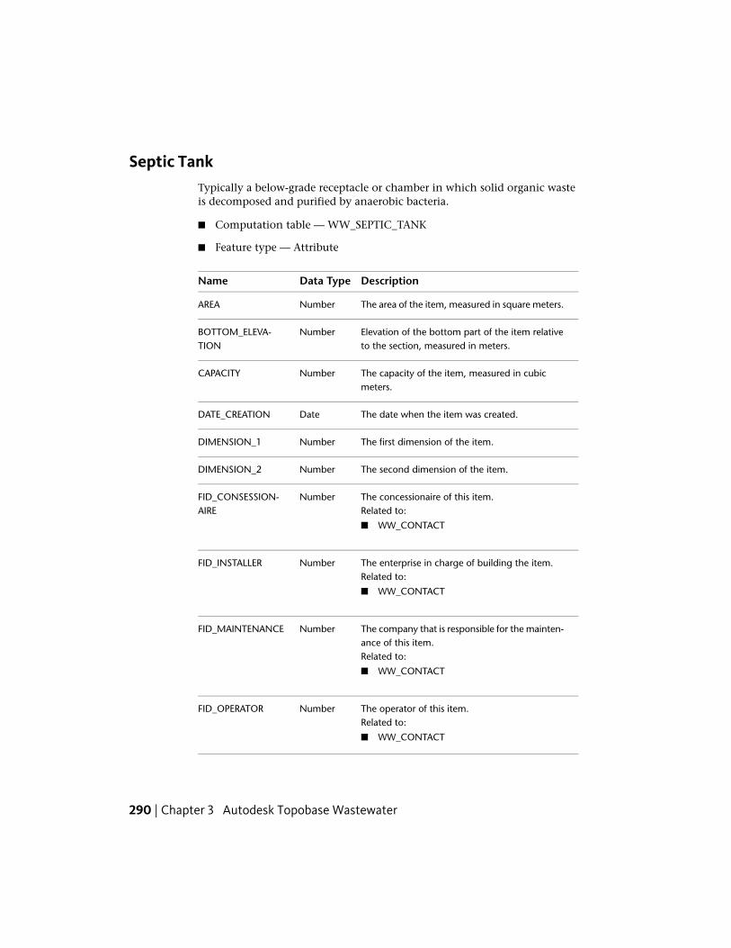
Septic TankTypically a below-grade receptacle or chamber in which solid organic wasteis decomposed and purified by anaerobic bacteria.
■ Computation table — WW_SEPTIC_TANK
■ Feature type — Attribute
DescriptionData TypeName
The area of the item, measured in square meters.NumberAREA
Elevation of the bottom part of the item relativeto the section, measured in meters.
NumberBOTTOM_ELEVA-TION
The capacity of the item, measured in cubicmeters.
NumberCAPACITY
The date when the item was created.DateDATE_CREATION
The first dimension of the item.NumberDIMENSION_1
The second dimension of the item.NumberDIMENSION_2
The concessionaire of this item.NumberFID_CONSESSION-AIRE Related to:
■ WW_CONTACT
The enterprise in charge of building the item.NumberFID_INSTALLERRelated to:
■ WW_CONTACT
The company that is responsible for the mainten-ance of this item.
NumberFID_MAINTENANCE
Related to:
■ WW_CONTACT
The operator of this item.NumberFID_OPERATORRelated to:
■ WW_CONTACT
290 | Chapter 3 Autodesk Topobase Wastewater

DescriptionData TypeName
The owner of this item.NumberFID_OWNERRelated to:
■ WW_CONTACT
The rate of flow of the item.NumberFLOW_RATE
The material used to construct this item.NumberID_MATERIALRelated to:
■ WW_MATERIAL_TBD
The structural condition of the item.NumberID_STRUCT_CONDI-TION Related to:
■ WW_STRUCT_CONDITION_TBD
The name or number of this item.Varchar2NAME_NUMBER
A description or other unique information con-cerning the subject item.
Varchar2NARRATIVE
The unique sequence identifier.NumberSEQUENCEID
An operator defined work area. This attribute canbe used by the operator for user defined system
Varchar2USER_FLAG
processes. It does not effect the subject item'sdata integrity and should not be used to storethe subject item's data.
For more information, see Network Point Creation (page 69).
Starch■ Computation table — WW_STARCH
Wastewater Feature Classes and Types | 291

■ Feature type — Attribute
DescriptionData TypeName
The capacity of the item, measured in cubicmeters.
NumberCAPACITY
The depth of the item, measured in meters.NumberDEPTH
The first dimension of the item, measured inmeters.
NumberDIMENSION_1
The second dimension of the item, measured inmeters.
NumberDIMENSION_2
The environmental parameters.Related to:
NumberFID_ENV_PARAMET-ERS
■ WW_ENV_PARAMETERS
The street location of this item.NumberFID_LOCATIONRelated to:
■ WW_LOCATION
The relation of the item to the site.NumberFID_SITERelated to:
■ WW_SITE
The fresh water ID.NumberID_FRESH_WATERRelated to:
■ WW_FRESH_WATER_TBD
The type of installation.NumberID_INSTALLA-TION_TYPE Related to:
■ WW_INSTALLATION_TYPE_TBD
The material used to construct this item.NumberID_MATERIALRelated to:
■ WW_MATERIAL_TBD
292 | Chapter 3 Autodesk Topobase Wastewater

DescriptionData TypeName
The input elevation, measured in meters.NumberINPUT_ELEVATION
The name or number of this item.Varchar2NAME_NUMBER
The nominal size.NumberNOMINAL_SIZE
The output elevation of the out flow, measuredin meters.
NumberOUTPUT_ELEVATION
For more information, see Network Point Creation (page 69).
StrainerA strainer is a type of sieve typically associated with separating liquids fromsolids.
■ Computation table — WW_STRAINER
■ Feature type — Attribute
DescriptionData TypeName
The manufacturer address.Varchar2ADDRESSOFMANU-FACTURER
The date when the item was created.DateDATE_CREATION
The environmental parameters.Related to:
NumberFID_ENV_PARAMET-ERS
■ WW_ENV_PARAMETERS
The street location of this item.NumberFID_LOCATIONRelated to:
■ WW_LOCATION
The state of the disposition of the item. For ex-ample, death, planed, etc.
NumberID_DISPOSI-TION_STATE
Related to:
■ WW_DISPOSITION_STATE_TBD
Wastewater Feature Classes and Types | 293

DescriptionData TypeName
The hydraulic function of the item.NumberID_HYDRAUL-IC_FUNCTION Related to:
■ WW_HYDRAULIC_FUNCTION_TBD
The installation ID.NumberID_INSTALLATIONRelated to:
■ WW_INSTALLATION_TBD
The type of installation.NumberID_INSTALLA-TION_TYPE Related to:
■ WW_INSTALLATION_TYPE_TBD
The material used to construct this item.NumberID_MATERIALRelated to:
■ WW_MATERIAL_TBD
The strainer body ID.NumberID_STRAINER_BODYRelated to:
■ WW_STRAINER_BODY_TBD
The strainer face ID.NumberID_STRAINER_FACERelated to:
■ WW_STRAINER_FACE_TBD
The strainer type ID.NumberID_STRAINER_TYPERelated to:
■ WW_STRAINER_TYPE_TBD
Is there a handover?NumberIS_HANDOVER
The LISA unique identifier.Varchar2LISA_GUID
A description of the manufacturer type.Varchar2MANUFAC-TURER_TYPE
The name or number of this item.Varchar2NAME_NUMBER
294 | Chapter 3 Autodesk Topobase Wastewater

DescriptionData TypeName
The additional name number of the item.Varchar2NAME_NUMBER_1
A description or other unique information con-cerning the subject item.
Varchar2NARRATIVE
The unique sequence indentifier.NumberSEQUENCEID
The UFIS construction number.NumberUFIS_CONSTRUC-TIONNUMBER
For more information, see Network Point Creation (page 69).
Treatment PlantA structure containing equipment used to treat or remove unwantedconstituents from wastewater.
■ Computation table — WW_TREATMENT_PLANT
■ Feature type — Attribute
DescriptionData TypeName
The manufacturer address.Varchar2ADDRESSOFMANU-FACTURER
The area of the item, measured in square meters.NumberAREA
Elevation of the bottom part of the item relativeto the section, measured in meters.
NumberBOTTOM_ELEVA-TION
The date when the item was created.DateDATE_CREATION
The first dimension of the item.NumberDIMENSION_1
The second dimension of the item.NumberDIMENSION_2
The concessionaire of this item.NumberFID_CONSESSION-AIRE Related to:
■ WW_CONTACT
Wastewater Feature Classes and Types | 295

DescriptionData TypeName
The environmental parameters.Related to:
NumberFID_ENV_PARAMET-ERS
■ WW_ENV_PARAMETERS
The enterprise in charge of building the item.NumberFID_INSTALLERRelated to:
■ WW_CONTACT
The street location of this item.NumberFID_LOCATIONRelated to:
■ WW_LOCATION
The company that is responsible for the mainten-ance of this item.
NumberFID_MAINTENANCE
Related to:
■ WW_CONTACT
The operator of this item.NumberFID_OPERATORRelated to:
■ WW_CONTACT
The owner of this item.NumberFID_OWNERRelated to:
■ WW_CONTACT
The actual rate of flow of the item.NumberFLOW_ACTUAL
The rated flow of the item.NumberFLOW_RATED
The state of the disposition of the item. For ex-ample, death, planed, etc.
NumberID_DISPOSI-TION_STATE
Related to:
■ WW_DISPOSITION_STATE_TBD
The hydraulic function of the item.NumberID_HYDRAUL-IC_FUNCTION Related to:
296 | Chapter 3 Autodesk Topobase Wastewater

DescriptionData TypeName
■ WW_HYDRAULIC_FUNCTION_TBD
The structural condition of the item.NumberID_STRUCT_CONDI-TION Related to:
■ WW_STRUCT_CONDITION_TBD
The type of treatment plant.NumberID_TREAT-MENT_PLANT_TYPE Related to:
■ WW_TREATMENT_PLANT_TYPE_TBD
Is there a handover?NumberIS_HANDOVER
The LISA unique identifier.Varchar2LISA_GUID
A description of the manufacturer type.Varchar2MANUFAC-TURER_TYPE
The name or number of this item.Varchar2NAME_NUMBER
The additional name number of the item.Varchar2NAME_NUMBER_1
A description or other unique information con-cerning the subject item.
Varchar2NARRATIVE
The number of pumps.NumberNR_PUMPS
The population equivalents.NumberPOPULATIONEQUI-VALENTS
The unique sequence identifier.NumberSEQUENCEID
The UFIS construction number.NumberUFIS_CONSTRUC-TIONNUMBER
An operator defined work area. This attribute canbe used by the operator for user defined system
Varchar2USER_FLAG
processes. It does not effect the subject item'sdata integrity and should not be used to storethe subject item's data.
Wastewater Feature Classes and Types | 297

For more information, see Network Point Creation (page 69).
ValveA fitting or device that is used for controlling flow through a wastewater line.
■ Computation table — WW_VALVE
■ Feature type — Attribute
DescriptionData TypeName
The manufacturer address.Varchar2ADDRESSOFMANU-FACTURER
Elevation of the bottom part of the item relativeto the section, measured in meters.
NumberBOTTOM_ELEVA-TION
The date when the item was created.DateDATE_CREATION
The first dimension of the item.NumberDIMENSION_1
The concessionaire of this item.NumberFID_CONSESSION-AIRE Related to:
■ WW_CONTACT
The environmental parameters.Related to:
NumberFID_ENV_PARAMET-ERS
■ WW_ENV_PARAMETERS
The enterprise in charge of building the item.NumberFID_INSTALLERRelated to:
■ WW_CONTACT
The street location of this item.NumberFID_LOCATIONRelated to:
■ WW_LOCATION
298 | Chapter 3 Autodesk Topobase Wastewater

DescriptionData TypeName
The company that is responsible for the mainten-ance of this item.
NumberFID_MAINTENANCE
Related to:
■ WW_CONTACT
The manufacturer of this item.NumberFID_MANUFAC-TURER Related to:
■ WW_MANUFACTURER
The operator of this item.NumberFID_OPERATORRelated to:
■ WW_CONTACT
The owner of this item.NumberFID_OWNERRelated to:
■ WW_CONTACT
The state of the disposition of the item. For ex-ample, death, planed, etc.
NumberID_DISPOSI-TION_STATE
Related to:
■ WW_DISPOSITION_STATE_TBD
The hydraulic function of the item.NumberID_HYDRAUL-IC_FUNCTION Related to:
■ WW_HYDRAULIC_FUNCTION_TBD
The service type of the valve.NumberID_SERVICE_TYPERelated to:
■ WW_SERVICE_TYPE_TBD
The state of the valve.NumberID_VALVE_STATERelated to:
■ WW_VALVE_STATE_TBD
The typeof valve.NumberID_VALVE_TYPE
Wastewater Feature Classes and Types | 299
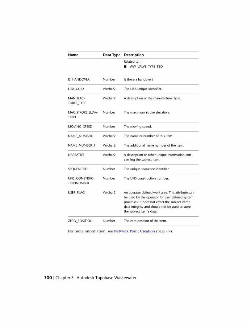
DescriptionData TypeName
Related to:
■ WW_VALVE_TYPE_TBD
Is there a handover?NumberIS_HANDOVER
The LISA unique identifier.Varchar2LISA_GUID
A description of the manufacturer type.Varchar2MANUFAC-TURER_TYPE
The maximum stroke elevation.NumberMAX_STROKE_ELEVA-TION
The moving speed.NumberMOVING_SPEED
The name or number of this item.Varchar2NAME_NUMBER
The additional name number of the item.Varchar2NAME_NUMBER_1
A description or other unique information con-cerning the subject item.
Varchar2NARRATIVE
The unique sequence identifier.NumberSEQUENCEID
The UFIS construction number.NumberUFIS_CONSTRUC-TIONNUMBER
An operator defined work area. This attribute canbe used by the operator for user defined system
Varchar2USER_FLAG
processes. It does not effect the subject item'sdata integrity and should not be used to storethe subject item's data.
The zero position of the item.NumberZERO_POSITION
For more information, see Network Point Creation (page 69).
300 | Chapter 3 Autodesk Topobase Wastewater

Wastewater Network PointA wastewater point stores the network points that are the network topologynodes. These points can be related to a site and can have one or more relatedgeometry details (WW_POINT_DETAIL_xx).
DescriptionWastewater Network Point
TopologyTopic
WW_POINT, point feature class.Table name
You can assign a site to describe the loca-tion.
FID_SITE
Standard attribute to store a height, forexample, terrain elevation of a manhole.
Z
ProfileThe Profile topic stores the profile feature classes.
DescriptionName
A profile system table used to store the profile origin.TB_PROFILE
A profile system table used to store the profile axis.TB_PROFILE_AXIS
Profile feature classes used to store the profile drawing.WW_xxx_PRO
For more information, see Working with Profiles.
ProtectionUse three basic feature classes to display and manage wastewater networkprotection: anode (point), anode test station (point), and casing (polygon).
Both anodes and casings are usually related to a section. The best way to accessthose feature classes is to use the predefined Protection Creation workflow.
For more information, see Protection Creation (page 74).
Wastewater Feature Classes and Types | 301

AnodeAn anode is made of a sacrificial material that is more reactive than the materialused to make a cathode (for example, a pipe). The anode is electricallyconnected to the cathode. When an electrical current is passed between theanode and the cathode, the current starts a chemical reaction where the anode,being the more reactive of the two materials, corrodes. This leaves the cathodeundamaged.
■ Computation table — WW_ANODE
■ Feature type — Point
DescriptionData TypeName
The anode weight quantity, measured in kilo-grams.
NumberANODE_WEIGHT
The date when the item was created.DateDATE_CREATION
The date when the item was inspected.DateDATE_INSPECTED
The concessionaire of this item.NumberFID_CONSESSION-AIRE Related to:
■ WW_CONTACT
The enterprise in charge of building the item.NumberFID_INSTALLERRelated to:
■ WW_CONTACT
The company that is responsible for the mainten-ance of this item.
NumberFID_MAINTENANCE
Related to:
■ WW_CONTACT
The operator of this item.NumberFID_OPERATORRelated to:
■ WW_CONTACT
The owner of this item.NumberFID_OWNER
302 | Chapter 3 Autodesk Topobase Wastewater

DescriptionData TypeName
Related to:
■ WW_CONTACT
The relation with the section.NumberFID_SECTIONRelated to:
■ WW_SECTION
Feature geometry polyline. For more information,see Oracle Spatial Users Guide and Reference.
GeometryGEOM
The anode material ID.NumberID_ANODE_MATERI-AL Related to:
■ WW_HYDRAULIC_FUNCTION_TBD
The name or number of this item.Varchar2NAME_NUMBER
A description or other unique information con-cerning the subject item.
Varchar2NARRATIVE
An operator defined work area. This attribute canbe used by the operator for user defined system
Varchar2USER_FLAG
processes. It does not effect the subject item'sdata integrity and should not be used to storethe subject item's data.
Anode Test StationA central location where anodes are tested for performance in wastewatersystems.
■ Computation table — WW_ANODE_TEST_STATION
■ Feature type — Point
DescriptionData TypeName
The date when the item was created.DateDATE_CREATION
Wastewater Feature Classes and Types | 303

DescriptionData TypeName
The concessionaire of this item.NumberFID_CONSESSION-AIRE Related to:
■ WW_CONTACT
The enterprise in charge of building the item.NumberFID_INSTALLERRelated to:
■ WW_CONTACT
The company that is responsible for the mainten-ance of this item.
NumberFID_MAINTENANCE
Related to:
■ WW_CONTACT
The operator of this item.NumberFID_OPERATORRelated to:
■ WW_CONTACT
The owner of this item.NumberFID_OWNERRelated to:
■ WW_CONTACT
Feature geometry polyline. For more information,see Oracle Spatial Users Guide and Reference.
GeometryGEOM
The insulation type code.NumberID_INSULA-TION_TYPE Related to:
■ WW_INSULATION_TYPE_TBD
The type of anode test station.NumberID_TYPERelated to:
■ WW_ANODE_TEST_STATION_TBD
The name or number of this item.Varchar2NAME_NUMBER
A description or other unique information con-cerning the subject item.
Varchar2NARRATIVE
304 | Chapter 3 Autodesk Topobase Wastewater

DescriptionData TypeName
The number of terminals.NumberNO_TERMINAL
The orientation of the anode test station.NumberORIENTATION
The quality of the sign.NumberQUALITY
An operator defined work area. This attribute canbe used by the operator for user defined system
Varchar2USER_FLAG
processes. It does not effect the subject item'sdata integrity and should not be used to storethe subject item's data.
The size of the wire, measured in meters.NumberWIRE_SIZE
The type of anode test station.NumberWIRE_TYPERelated to:
■ WW_WIRE_TYPE_TBD
The height value, measured in meters.NumberZ
CasingA material used to encase and protect sections of the wastewater system.
■ Computation table — WW_CASING
■ Feature type — Polygon
DescriptionData TypeName
The area of the item, measured in square meters.NumberAREA
Description of cadastral information, such as landboundaries, structure locations, boundary dimen-sions, etc.
Varchar2CADASTRAL_INFO
The length of the item, measured in squaremeters.
NumberCASING_LENGTH
Wastewater Feature Classes and Types | 305

DescriptionData TypeName
A description of the item's DIN/ISO/DVGW/TUEVvalue.
Varchar2CERTIFICATE
A description of objects which are crossed (belowsurface) by this item. for example, roads, rivers,buildings, railways, etc.
Varchar2CROSSED_OBJECT
The date when the data was acquired.DateDATE_ACQUIRED
The date when the item was created.DateDATE_CREATION
The date when responsibility of the item wastaken.
DateDATE_STARTUP
The inside diameter of the section.NumberDIAMETER_INSIDE
The manufacturer's designated size, or nominaldiameter (rounded to the nearest unit), for the
Varchar2DIAMETER_NOMIN-AL
subject item. For example, 1" gas hydrant, 2"meter, 6" pipe, etc.
The outside diameter of the section.NumberDIAMETER_OUTSIDE
The concessionaire of this item.NumberFID_CONSESSION-AIRE Related to:
■ WW_CONTACT
The enterprise in charge of building the item.NumberFID_INSTALLERRelated to:
■ WW_CONTACT
The company that is responsible for the mainten-ance of this item.
NumberFID_MAINTENANCE
Related to:
■ WW_CONTACT
The manufacturer of this item.NumberFID_MANUFAC-TURER Related to:
■ WW_MANUFACTURER
306 | Chapter 3 Autodesk Topobase Wastewater

DescriptionData TypeName
The operator of this item.NumberFID_OPERATORRelated to:
■ WW_CONTACT
The owner of this item.NumberFID_OWNERRelated to:
■ WW_CONTACT
The relation with one section.NumberFID_SECTIONRelated to:
■ WW_SECTION
Feature geometry polyline. For more information,see Oracle Spatial Users Guide and Reference.
GeometryGEOM
The elevation of the item relative to the ground.NumberGROUND_ELEVA-TION
The house address.Varchar2HOUSE
The house address supplement.Varchar2HOUSE_SUPPLE-MENT
The hydraulic friction or roughness along the in-side the section; what decreases the pressure rel-ative to the length.
NumberHYDRAULIC_FRIC-TION
How the current position of the item was determ-ined. For example, exactly, by positioning, un-known, or inexactly.
NumberID_ACCURACY
Related to:
■ WW_ACCURACY_TBD
The type of coating along the inside of the sec-tion.
NumberID_COATING_INSIDE
Related to:
■ WW_COATING_TBD
Wastewater Feature Classes and Types | 307

DescriptionData TypeName
The type of coating along the outside of the sec-tion.
NumberID_COATING_OUT-SIDE
Related to:
■ WW_COATING_TBD
The condition of the item. For example, broken,leaking, etc.
NumberID_CONDITION
Related to:
■ WW_CONDITION_TBD
The state of the disposition of the item. For ex-ample, death, planed, etc.
NumberID_DISPOSI-TION_STATE
Related to:
■ WW_DISPOSITION_STATE_TBD
The type of foundation for this item.NumberID_FOUNDA-TION_TYPE Related to:
■ WW_FOUNDATION_TBD
How was the item placed at its location. Forexmaple, open ditch, laying on ground, etc.
NumberID_LAYING_TYPE
Related to:
■ WW_LAYING_TYPE_TBD
The location of the item (street).Related to:
NumberID_LOCATION
■ WW_LOCATION
The material used to manufacture this item.NumberID_MATERIAL
A brief description of where the item is located.For example, 1m from the wall.
Varchar2LOCATION
The model name or number of the item.Varchar2MODEL_NUMBER
The name or number of this item.Varchar2NAME_NUMBER
308 | Chapter 3 Autodesk Topobase Wastewater

DescriptionData TypeName
A description or other unique information con-cerning the subject item.
Varchar2NARRATIVE
The manufacturer's or industry standard's maxim-um pressure rating for the subject item.
NumberPRESSURE_MAX
The unique serial number of the manufacturer.Varchar2SERIAL_NUMBER
The thickness of the section wall.NumberTHICKNESS
An operator defined work area. This attribute canbe used by the operator for user defined system
Varchar2USER_FLAG
processes. It does not effect the subject item'sdata integrity and should not be used to storethe subject item's data.
A short description of the model. This value isused for the domain table representation of themodel.
Varchar2VALUE
SectionThe basic wastewater application contains one wastewater line feature; thesection. Network geometry is stored separately in the WW_LINE feature class.This feature class stores geometry only; not attributes, and is related to thewastewater feature, WW_LINE.FID_ATTR.
NOTE The records of the geometry feature classes are maintained by Topobase.Do not enhance geometry feature classes by adding customer attributes. Thegeometry feature classes build the network topology.
■ WW_LINE: line string feature class – network line; geometry
■ WW_SECTION: attribute feature class – utility line
Section feature models: The section feature class has a model table(WW_SECTION_MODEL).
Wastewater Feature Classes and Types | 309

Section Feature Class FormUse the basic feature class form of the wastewater section to view and edit thefeature attributes and to view related data.
The Section feature class form contains the following elements:
■ General tab — Displays general feature information.
■ Details tab — Displays detailed feature attributes and links to all pointfeatures the section is connected to.
■ Related Tables tab — Provides direct access to the following related tables:
DescriptionRelated Table
Information about section maintenance(WW_MAINTENANCE)
Maintenance
Casing for protection of the section(WW_CASING)
Casing
Anode for protection of the section(WW_ANODE)
Anode
(WW_SUB_DRAIN_AREA)Sub Drain Area
Line geometry (WW_LINE)Line
Label for pipe features (WW_PIPE_TBL)Label
■ Inspection Editor tab — Displays the inspection editor. See InspectionEditor (page 103).
■ Table tab — Displays all attributes in table form.
Some feature class forms provide functions for further processing of the selectedrecords. These functions can be accessed via menu or control buttons. See UseWastewater Feature Functions (page 82).
SectionA section is a wastewater channel or pipe between network points. Sectionsare the only standard line feature of a wastewater utility model.
310 | Chapter 3 Autodesk Topobase Wastewater

The data model stores both real pipe geometry and the network topology,which is a more abstract view. Physically, a pipe runs between two manholestructures and a manhole has a certain diameter. Topologically, a section runsfrom manhole (center) to manhole (center).
Use intermediate points to add detail so the line from manhole to manholeis more accurate.
NOTE In the wastewater document options, you can enable manhole/sectionvalidation. See Set Wastewater Document Options (page 333).
The manhole/section validation checks the consistency of the bottom heightin the section and manhole feature class. In the feature class form, attributesthat do not match are highlighted, and a tooltip explains the inconsistency.
Wastewater data model: Section between two manholes. Physically the section isrepresented by a pipe that runs between the manhole structures.
■ Computation table — WW_SECTION
■ Feature type — Attribute
DescriptionData TypeName
The average depth of the section.NumberAVG_DEPTH
Wastewater Feature Classes and Types | 311

DescriptionData TypeName
Description of cadastral information, such as landboundaries, structure locations, boundary dimen-sions, etc.
Varchar2CADASTRAL_INFO
Connection comments pertaining to the section.Varchar2CONNECTION_COM-MENTS
Description of cadastral information, such as landboundaries, structure locations, boundary dimen-sions, etc.
Varchar2CONNECTION_DES-IGNATION
The average depth of the section.NumberCONNECTION_DIS-TANCE
Description of cadastral information, such as landboundaries, structure locations, boundary dimen-sions, etc.
Varchar2CONNECTION_FIX-ING
The date when the data was acquired.DateDATE_ACQUIRED
The date when the item was created.DateDATE_CREATION
The date when responsibility of the item wastaken.
DateDATE_STARTUP
The inside diameter of the section.NumberDIAMETER_INSIDE
The outside diameter of the section.NumberDIAMETER_OUTSIDE
The first dimension of the item, measured inmeters.
NumberDIMENSION_1
The second dimension of the item, measured inmeters.
NumberDIMENSION_2
The distance covered by the section, measuredin meters.
NumberDISTANCE
The height above sea-level of the end point ofthe section, measured in meters.
NumberEND_Z
312 | Chapter 3 Autodesk Topobase Wastewater

DescriptionData TypeName
The existing special profile of the section.NumberEXIST_SPECIAL_PRO-FILE
The water fall height at the end of the section,measured in meters.
NumberFALL_HEIGHT
The concessionaire of this item.NumberFID_CONSESSION-AIRE Related to:
■ WW_CONTACT
The drain area of the section.NumberFID_DRAIN_AREARelated to:
■ WW_DRAIN_AREA
The relation to the environmental parameters.NumberFID_ENV_PARAMET-ERS Related to:
■ WW_ENV_PARAMETERS
The enterprise in charge of building the item.NumberFID_INSTALLERRelated to:
■ WW_CONTACT
The location of the item (street).Related to:
NumberFID_LOCATION
■ WW_LOCATION
The company that is responsible for the mainten-ance of this item.
NumberFID_MAINTENANCE
Related to:
■ WW_CONTACT
The manufacturer of this item.NumberFID_MANUFAC-TURER Related to:
■ WW_MANUFACTURER
The operator of this item.NumberFID_OPERATOR
Wastewater Feature Classes and Types | 313

DescriptionData TypeName
Related to:
■ WW_CONTACT
The owner of this item.NumberFID_OWNERRelated to:
■ WW_CONTACT
The treament plant related to this item. SeeTreatment Plant (page 295)
NumberFID_TREAT-MENT_PLANT
Related to:
■ WW_TREATMENT_PLANT
The washing area in which the section is placed.See Washing Area (page 130).
NumberFID_WASHING_AREA
Related to:
■ WW_WASHING_AREA
The file related to this item.Varchar2FILE_NAME
The fixing entry.Varchar2FIXING
The group section.Varchar2GROUP_SECTION
Hydraulic friction or the roughness inside a sec-tion which decreases the pressure relative to thelength.
NumberHYDRAULIC_FRIC-TION
How the current position of the item was determ-ined. For example, exactly, by positioning, un-known, or inexactly.
NumberID_ACCURACY
Related to:
■ WW_ACCURACY_TBD
The type of cathodic protection applied to thesection. For example, victim anode, AC, DC, etc.
NumberID_CATHODIC_PRO-TECTION
Related to:
■ WW_CATHODIC_PROTECTION_TBD
314 | Chapter 3 Autodesk Topobase Wastewater

DescriptionData TypeName
The type of coating along the inside of the sec-tion.
NumberID_COATING_INSIDE
Related to:
■ WW_COATING_TBD
The type of coating along the outside of the sec-tion.
NumberID_COATING_OUT-SIDE
Related to:
■ WW_COATING_TBD
The condition of the item. For example, broken,leaking, etc.
NumberID_CONDITION
Related to:
■ WW_CONDITION_TBD
The connection edge type ID.NumberID_CONNEC-TION_EDGE_TYPE Related to:
■ WW_CONNECTION_EDGE_TYPE_TBD
The connection type ID.NumberID_CONNEC-TION_TYPE Related to:
■ WW_CONNECTION_TYPE_TBD
The additional constructed element on the profile.NumberID_CONSTR_PROFILERelated to:
■ WW_CONSTR_PROFILE_TBD
The data origin ID.NumberID_DATA_ORIGINRelated to:
■ WW_DATA_ORIGIN_TBD
The disposition state of the item. For example,death, planed, etc.
NumberID_DISPOSI-TION_STATE
Related to:
■ WW_DISPOSITION_STATE_TBD
Wastewater Feature Classes and Types | 315

DescriptionData TypeName
The drainage pattern code.NumberID_DRAIN_PATTERNRelated to:
■ WW_DRAIN_PATTERN_TBD
Defines whether the section is in a floodplain.NumberID_FLOODPLAINRelated to:
■ WW_FLOODPLAIN_TBD
The type of foundation.NumberID_FOUNDATIONRelated to:
■ WW_FOUNDATION_TBD
The function ID.NumberID_FUNCTIONRelated to:
■ WW_FUNCTION_TBD
The groundwater ID.NumberID_GROUNDWATERRelated to:
■ WW_GROUNDWATER_TBD
The accuracy of the elevation.NumberID_HEIGHT_ACCUR-ACY Related to:
■ WW_HEIGHT_ACCURACY_TBD
The hydraulic function of the item.NumberID_HYDRAUL-IC_FUNCTION Related to:
■ WW_HYDRAULIC_FUNCTION_TBD
Describes how the item was placed on its loca-tion. For example, open ditch, laying on ground,etc.
NumberID_LAYING_TYPE
Related to:
■ WW_LAYING_TYPE_TBD
The lining ID.NumberID_LINING
316 | Chapter 3 Autodesk Topobase Wastewater

DescriptionData TypeName
Related to:
■ WW_LINING_TBD
The lining material ID.NumberID_LINING_MATERI-AL Related to:
■ WW_MATERIAL_TBD
Describes how the item is marked on the ground.For example, marker, magnetic tape, tape, etc.
NumberID_MARKER_TYPE
Related to:
■ WW_MARKER_TYPE_TBD
The material used to construct this item.NumberID_MATERIALRelated to:
■ WW_MATERIAL_TBD
The material origin ID.NumberID_MATERIAL_ORI-GIN Related to:
■ WW_MATERIAL_ORIGIN_TBD
Describes any other construction placed in thesection.
NumberID_OTHER_CON-STRUCTION
Related to:
■ WW_OTHER_CONSTR_TBD
The owner of this item.NumberID_OWNERSHIPRelated to:WW_OWNERSHIP_TBD
The pressure procedure ID.NumberID_PRESSURE_PRO-CEDURE Related to:
WW_PRESSURE_PROCEDURE_TBD
Describes the profile of the section.NumberID_PROFILERelated to:WW_PROFILE_TBD
Wastewater Feature Classes and Types | 317

DescriptionData TypeName
The profile origin ID.NumberID_PROFILE_ORIGINRelated to:WW_PROFILE_ORIGIN_TBD
Describes the restoration or replacement of thesection. For example, concrete, epoxy, fitting,etc.
NumberID_RENOVATION
Related to:WW_RENOVATION_TBD
The type of soil.NumberID_SOIL_TYPERelated to:
■ WW_SOIL_TYPE_TBD
The state of the traffic passing over the section.NumberID_TRAFFIC_SITU-ATION Related to:
■ WW_TRAFFIC_SITUATION_TBD
The utilization of the section.NumberID_UTILISATIONRelated to:
■ WW_UTILISATION_TBD
The degree of water protection.NumberID_WATER_PROTEC-TION Related to:
■ WW_WATER_PROTECTION_TBD
The depth of the section at the start of the sec-tion, measured in meters.
NumberINPUT_DEPTH
The difference between the soil elevation and theinput elevation in the start manhole, measuredin meters.
NumberINPUT_STEP
The height above sea level at the input point ofthe section, measured in meters.
NumberINPUT_Z
The LISA unique identifier.Varchar2LISA_GUID
318 | Chapter 3 Autodesk Topobase Wastewater

DescriptionData TypeName
A brief description of where the item is located.For example, 1m from the wall.
Varchar2LOCATION
The maximum flow possible through the section.NumberMAX_FLOW
The maximum pressure rating of the section.NumberMAX_PRESSURE
The name or number of this item.Varchar2NAME_NUMBER
Additional name number of the item.Varchar2NAME_NUMBER_1
A description or other unique information con-cerning the subject item.
Varchar2NARRATIVE
The depth of the section at the end of the section,measured in meters.
NumberOUTPUT_DEPTH
The height above sea level at the output point ofthe section, measured in meters.
NumberOUTPUT_Z
The length of the physical pipe, measured inmeters.
NumberPIPE_LENGTH
The slope of the physical pipe.NumberPIPE_SLOPE
The pressure rating of the section.NumberRATEDPRESSURE
The regular individual pipe length.NumberREGULARINDIVIDU-ALPIPELENGTH
The unique sequence identifier.NumberSEQUENCEID
The unique serial number of the manufacturer.Varchar2SERIAL_NUMBER
The height above sea level at the start point ofthe section, measured in meters.
NumberSTART_Z
The thickness of the pipe wall.NumberTHICKNESS
Wastewater Feature Classes and Types | 319

DescriptionData TypeName
The 2D length of the section; the total lengthbetween the manholes, measured in documentunits.
NumberTOTAL_LENGTH
The computed slope of the section.NumberTOTAL_SLOPE
The reference to the transit right document onprivate parcel.
Varchar2TRANS-IT_RIGHT_DOCU-MENT
An operator defined work area. This attribute canbe used by the operator for user defined system
Varchar2USER_FLAG
processes. It does not effect the subject item'sdata integrity and should not be used to storethe subject item's data.
A short description of the model. This value isused for the domain table representation of themodel.
Varchar2VALUE
See also:
■ Wastewater Elevation, Slope, and Height (page 335)
■ Section Creation (page 70)
■ Intermediate Point (page 260)
■ Section Remove (page 71)
SiteA site consists of one master feature class (attribute) with related line, pointand polygon feature classes. Each network point can be connected to a site.
Sites are not part of the network topology. They are a useful means to groupvarious features of the utility network to make them reachable. A site storesfor example house number and location.
The easiest way to connect a network point to a site is to use the NetworkPoint Creation workflow.
320 | Chapter 3 Autodesk Topobase Wastewater

Use the Site Creation workflow to create sites that by default are related toone geometry feature. However, you can add more geometries and equipmentfeatures using the feature class form.
See also:
■ Site Creation (page 73)
■ Connect Points to Site (page 89)
■ Remove Connections from a Site (page 89)
Construction PartThe construction part feature class manages additional attributes of thestructural part of a manhole.
■ Feature class — WW_CONSTRUCTION_PART
■ Feature type — Attribute
DescriptionData TypeName
The relation to the manhole feature.NumberFID_MANHOLERelated to:
■ WW_MANHOLE
The height value.NumberHEIGHT
Describes the shape of the construction.NumberID_CONSTRUC-TION_SHAPE Related to:
■ WW_CONSTRUCTION_SHAPE_TBD
The material used to construct this item.NumberID_MATERIALRelated to:
■ WW_MATERIAL_TBD
The structural part ID.NumberID_STRUCTUR-AL_PART Related to:
■ WW_STRUCTURAL_PART_TBD
Wastewater Feature Classes and Types | 321

DescriptionData TypeName
The length value.NumberLENGH
A description or other unique information con-cerning the subject item.
Varchar2NARRATIVE
The number of structural parts.NumberNR_STRUCTUR-AL_PARTS
The width value.NumberWIDTH
SiteThe Site feature class is used to enclose assemblies and make them reachableby fittings, valves, etc.
■ Feature class — WW_SITE
■ Feature type — Attribute
DescriptionData TypeName
The site manufacturer’s address.Varchar2ADDRESSOFMANU-FACTURER
Data transmission? [yes/no].NumberDATA_TRANSMIS-SION
The date when the data was acquired.DateDATE_ACQUIRED
The date when the item was created.DateDATE_CREATION
The date when responsibility of the item wastaken.
DateDATE_STARTUP
The concessionaire of this item.NumberFID_CONSESSION-AIRE Related to:
■ WW_CONTACT
322 | Chapter 3 Autodesk Topobase Wastewater

DescriptionData TypeName
The relation to the environmental parameters.NumberFID_ENV_PARAMET-ERS Related to:
■ WW_ENV_PARAMETERS
The enterprise in charge of building the item.NumberFID_INSTALLERRelated to:
■ WW_CONTACT
The location of the item (street).Related to:
NumberFID_LOCATION
■ WW_LOCATION
The company that is responsible for the mainten-ance of this item.
NumberFID_MAINTENANCE
Related to:
■ WW_CONTACT
The operator of this item.NumberFID_OPERATORRelated to:
■ WW_CONTACT
The owner of this item.NumberFID_OWNERRelated to:
■ WW_CONTACT
Use to store the site in site.NumberFID_SITERelated to:
■ WW_SITE
The treament plant related to this item. SeeTreatment Plant (page 295)
NumberFID_TREAT-MENT_PLANT
Related to:
■ WW_TREATMENT_PLANT
The site footprint.NumberFOOTPRINT
Wastewater Feature Classes and Types | 323

DescriptionData TypeName
The elevation of the item relative to the ground,measured in meters.
NumberGROUND_ELEVA-TION
The house number.Varchar2HOUSE
The house number supplement.Varchar2HOUSE_SUPPLE-MENT
How the current position of the item was determ-ined. For example, exactly, by positioning, un-known, or inexactly.
NumberID_ACCURACY
Related to:
■ WW_ACCURACY_TBD
The condition of the item. For example, broken,leaking, etc.
NumberID_CONDITION
Related to:
■ WW_CONDITION_TBD
The disposition state of the item. For example,death, planed, etc.
NumberID_DISPOSI-TION_STATE
Related to:
■ WW_DISPOSITION_STATE_TBD
The type of foundation.NumberID_FOUNDATIONRelated to:
■ WW_FOUNDATION_TBD
The function ID.NumberID_FUNCTIONRelated to:
■ WW_FUNCTION_TBD
The hydraulic function of the item.NumberID_HYDRAUL-IC_FUNCTION Related to:
■ WW_HYDRAULIC_FUNCTION_TBD
324 | Chapter 3 Autodesk Topobase Wastewater

DescriptionData TypeName
Describes how the item was placed on its loca-tion. For example, open ditch, laying on ground,etc.
NumberID_LAYING_TYPE
Related to:
■ WW_LAYING_TYPE_TBD
The street location of this item.NumberID_LOCATIONRelated to:
■ WW_LOCATION
Describes how the item is marked on the ground.For example, marker, magnetic tape, tape, etc.
NumberID_MARKER_TYPE
Related to:
■ WW_MARKER_TYPE_TBD
The material used to construct this item.NumberID_MATERIALRelated to:
■ WW_MATERIAL_TBD
The owner of this item.NumberID_OWNERSHIPRelated to:WW_OWNERSHIP_TBD
The plant combination ID.NumberID_PLANT_COMBIN-ATION Related to:
WW_PLANT_COMBINATION_TBD
Describes the kind of site.NumberID_TYPERelated to:WW_SITE_TYPE_TBD
Is there a bypass?NumberIS_BYPASS
Is there a plant combination?NumberIS_PLANT_COMBINA-TION
Is there a handover?NumberIS_HANDOVER
Wastewater Feature Classes and Types | 325

DescriptionData TypeName
The LISA unique identifier.Varchar2LISA_GUID
A brief description of where the item is located.For example, 1m from the wall.
Varchar2LOCATION
A description of the manufacturer type.Varchar2MANUFAC-TURER_TYPE
The name or number of this item.Varchar2NAME_NUMBER
Additional name number of the item.Varchar2NAME_NUMBER_1
A description or other unique information con-cerning the subject item.
Varchar2NARRATIVE
The unique sequence identifier.NumberSEQUENCEID
The unique serial number of the manufacturer.Varchar2SERIAL_NUMBER
The service provided by this site.Varchar2SERVICE
The depth dimension of the item, measured inmeters.
NumberSITE_DEPTH
The length dimension of the item, measured inmeters.
NumberSITE_LENGTH
The width dimension of the item, measured inmeters.
NumberSITE_WIDTH
The space above ground, measured in meters.NumberSPACE_ABOVE_GROUND
The space below ground, measured in meters.NumberSPACE_BE-LOW_GROUND
The UFIS construction number.NumberUFIS_CONSTRUC-TIONNUMBER
An operator defined work area. This attribute canbe used by the operator for user defined system
Varchar2USER_FLAG
processes. It does not effect the subject item's
326 | Chapter 3 Autodesk Topobase Wastewater

DescriptionData TypeName
data integrity and should not be used to storethe subject item's data.
UtilityThe utility model allows you to separate the geometries from attributes. Thislets you maintain complex network topologies with soft and hard split points.
For example, a house connection is connected to one main section. If youconnect an additional house, you don’t want to split the main. Instead, youshould connect the new house connection to the main pipe. In this case, theconnection is done using a soft split.
The utility model has several feature rules which maintain the network.
DescriptionUtility
UtilityTopic
WW_POINT, point feature class.Table nameWW_LINE, line geometry.
Wastewater Feature RulesMany feature classes in the wastewater data model are comprised of featurerules. Use the data model administrator to view, enable, or disable featurerules.
Feature rules are methods and triggers that process data according to predefinedalgorithms. For example, feature rules perform consistency and dependencychecks at certain events, such as before inserting or after modifying a featureclass. A number of predefined feature rules are available, or you can defineyour own server-side feature rules or create client-side feature rules.
When you run Data Acquisition workflows in the wastewater application,feature rules improve the efficiency of adding feature classes and ensuringdata consistency.
To explore wastewater feature rules
1 Start Topobase Administrator and open the Wastewater workspace.
Wastewater Feature Rules | 327

2 Start the data model administrator. Select the document. Click Documentmenu ➤ Data Model.
3 In the data model explorer, right-click the feature class. Click Edit FeatureRules.
4 In the Feature Rules Properties dialog box, click the Client Side (.NET)tab.
To disable or enable a feature rule
1 Start the data model administrator and select the document.
2 In the data model explorer under the Administration topic, select thefeature class, such as Washing Area.
3 Right-click the feature class and click Edit Feature Rules.
4 In the Feature Rules Properties dialog box, click the Client Side (.NET)tab.
5 To enable or disable a feature rule, do one of the following:
■ In the Applied Rule Bases list, select or clear the feature rule.
■ In the Rule Base Definitions list, click a definition row and click Addto move the item to the Applied Rule Bases list.
6 Click Save and Close.
For more information regarding feature rules, see the Topobase Feature RulesReference.
Feature Rules: ManholeThe manhole feature rules check the number of sections, section elevationand cover elevation values when a manhole is added or modified.
■ Compute Number of Sections — For new manholes, calculates the numberof incoming and outgoing sections and stores the number in the attributesNR_INPUT_SECTION and NR_OUTPUT_SECTION.
■ Compute Section Elevation — Computes some values of the section, itsmanholes, and their covers.
328 | Chapter 3 Autodesk Topobase Wastewater
NOTE You must configure the computation of elevation, slope, and heightsin the wastewater document options. See Set Wastewater Document Options(page 333).
To learn more about section elevation, see Wastewater Elevation, Slope,and Height (page 335).
■ Compute Elevation — The cover height is stored in a Cover Z attributewhich is the difference between the soil elevation and the terrain elevation.To learn more about height, see Wastewater Elevation, Slope, and Height(page 335).
See also:
■ Manhole (page 264)
Feature Rules: Sub Drain AreaThe sub drain area feature rules check the sub-drain area, sub-drain area drains,sub-drain area sections, sub-drain area manholes, and the transferal of valuesfrom the model table to the sub-drain area table.
Each sub-drain area can belong to one drain area. This relation is stored inthe attribute WW_SUB_DRAIN_AREA.FID_DRAIN_AREA.
Also, feature rules calculate some values, transfer values from the model table,and connect the sub-drain area to a section or a manhole.
■ Compute Sub Drain Area — Calculates the following significant values:COVERED_AREA = AREA * DISCHARGE_COEFFICIENT
NOT_COVERED_AREA = AREA * (1-DISCHARGE_COEFFICIENT)
INHABITANT_DENSITY = INHABITANT/HECTARE [ha]
See WW_ComputeSubDrainArea_BIU.
■ Connect Sub Drain Area Drain Area — Connects a sub-drain area to thedrain area, when you digitize a sub-drain area that lies within a drain area.When two or more drain areas are found, they are highlighted and youcan select which one to assign. See WW_ConnSubAreaWDrainArea_BIU.
■ Connect Sub Drain Area Section — Connects a section with a sub-drainarea if it is contained in the sub-drain area. Also, this rule checks whetherthe utilization for the sub-drain area and the section match. See
Wastewater Feature Rules | 329

WW_ConnSubDrainAreaSection_BU orWW_ConnSubDrainAreaSection_BU.
■ Connect Sub Drain Area Manhole — Connects the start manhole or endmanhole of a section with a sub-drain area if it is contained in this area.Also, this rule checks whether the utilization for the sub-drain area andthe manhole match. See WW_ConnSubDrainAreaManhole_BIU.
■ Transfer Value from Model — When you select a model for the sub-drainarea, this rule transfers the corresponding value from the model table tothe sub-drain area table.
In Topobase Administrator, you can disable the feature rules. See WastewaterFeature Rules (page 327).
See also:
■ Sub Drain Area (page 132)
Feature Rules: Washing AreaThe washing area feature rules allow you to connect washing areas to sectionsor sections to a washing area. (WW_SECTION.FID_WASHING_AREA).
■ Connect Washing Area to a Section — When a washing area is specified,this rule automatically connects existing sections that fall within thatwashing area. See WW_ConnWashingAreaSection_BIU.
■ Connect Section to a Washing Area — When a section is added that lieswithin an existing washing area, this rule connects the section to thewashing area. When two or more washing areas are found, they arehighlighted so you can select which one to assign to the section. SeeWW_ConnSectionWashingArea_BI.
Use the Topobase Administrator to enable and disable feature rules.
Explore Stop ConditionsNetwork topologies are comprised of predefined stop conditions. You canview them with the Data Model administrator.
330 | Chapter 3 Autodesk Topobase Wastewater

To explore stop conditions
1 Start Topobase Administrator and open the Wastewater workspace.
2 Click Document menu ➤ Data Model to select the document.
3 In the data model explorer, expand Topologies.
4 Expand a topology and expand the Conditions folder.
5 Right-click the stop condition you want to view and click Properties.
The Tracing Condition dialog box is displayed.
6 View or edit the setting for the stop condition or click Cancel to exit.
For more information about defining conditions, see Network Tracer.
See also:
■ Stop Condition Editor
Explore Wastewater TopologiesThe Topobase wastewater data model contains the wastewater networktopology, which is built from the point feature class (WW_POINT) and thesection feature class (WW_LINE).
Explore Wastewater Topologies | 331

Topobase Wastewater network topology
Only the point feature classes of the Point topic and the section feature classof the Section topic are part of the wastewater network topology.
Network topology tables have the suffixes _NNOD (topology nodes) and_NLNK (topology links).
Other feature classes, such as the Protection or the Site feature classes, are notpart of the network topology.
Achieving a Valid Network Topology
The topology requires that network points always lie at the start or end of anetwork line. A network point must never lie on a line. If you insert a networkpoint on a network line, the line must be split at the insertion point. Theconsistency of the topology is maintained by feature rules.
If you remove a network point, you must merge the connecting lines.
For more information, see Intermediate Point (page 260), Split Lines (page 92),and Extract Points from Lines (page 95).
For more information about the feature rules, see Understand and Work withthe Wastewater Data Model (page 111)
332 | Chapter 3 Autodesk Topobase Wastewater

Set Wastewater Document OptionsUse the wastewater document options to specify how feature rules andfunctions of features shall be applied.
To set wastewater document options
1 On the ribbon, click Settings tab ➤ Setup panel ➤ Document Options.
2 In the tree view, click Wastewater.
3 Make one or more of the following types of settings:
■ Click the General tab to specify general options.
■ Click the Elevation Computation Priority tab to specify whichelevation values get calculated automatically.
■ Click the Inspection Management tab to specify the defaultclassification model.
Select options as shown in the following table
DescriptionWastewater Document Options
General tab
Specifies the search distance for the auto-matic connection of points and covers.
Tolerances
Enables or disables validation.ValidationSelect Manhole/Section to check heightconsistency. See Section (page 310).Select Sub Drain Area Model to check themodel parameters. See Sub Drain Area(page 132).
Specifies the values that are calculatedautomatically, such as cover height, section
Elevation Computation Priority tab
fall height. Select the values and use thearrow buttons to change the priority.
Set Wastewater Document Options | 333

DescriptionWastewater Document Options
To aid in PIPE_LENGTH andTOTAL_LENGTH calculations, use the CopyValues option to specify if the INPUT_Z andOUTPUT_Z values are automatically copiedto START_Z and END_Z values, respect-ively.See also Wastewater Elevation, Slope, andHeight (page 335).
Inspection Management tab
Select one of the classification models.When Topobase cannot find the import
Classification
data types, the selected classificationmodel is used as default to classify impor-ted data.
■ DWA-M 149-3 — The default standardused for the automated classificationof wastewater objects. The successorto the ATV standard.
■ ISYBAU 2006 (XML) — Set for classific-ation based on the ISYBAU XMLstandard. This standard is newer thanthe ISYBAU 96 standard.
■ ISYBAU 1996 — Set for classificationbased on the ISYBAU 1996 standard.
■ ISYBAU 2001 — Set for classificationbased on the ISYBAU 2001 standard.
See also Inspection File Formats (page 108).
Enables or disables section length check,and specifies a tolerance value (%). When
Inspection Length Check
importing inspection data, the inspectionlength is checked against its correspondingsection length.When the difference is below the tolerance,the inspection length will be adjusted.When the difference is above the tolerance,a message is displayed.
334 | Chapter 3 Autodesk Topobase Wastewater

DescriptionWastewater Document Options
Specifies a length below which the inspec-tion length will not be applied.
Minimum Section Length To Be Con-sidered
Wastewater Elevation, Slope, and HeightElevation management ensures consistent values for the heights of relatedcovers, manholes, and sections. The relation between the elevation of thewastewater feature heights and measured depths must be validated. Valuesthat can both be measured or calculated can be compared to validate eachother. For example, bottom elevation plus the depth of a manhole shouldresult in the cover height.
Height is a terrain elevation or a height above sea level. Height is usually storedin a *_Z attribute. Depth is a value that is usually measured with a meter rule.
For wastewater networks, the storage of heights and slopes is very important.The data model provides both a simple and a detailed approach. You caneither store the network by simply connecting manholes or you can useintermediate points for a more detailed model. You can also refine the networkaccording to your workflow. First, the surveyor measures the covers aboveground. Next, the wastewater specialist measures the wastewater networkunderground with exact coordinates and heights.
If you do not use intermediate points for the entries of the sections into themanhole or manhole structure, the following values are valid for the section:
■ START_Z = INPUT_Z
■ END_Z = OUTPUT_Z
Wastewater Elevation, Slope, and Height | 335

The Topobase Wastewater data model stores section attributes in either a simplifiedor a detailed structure.
The Compute Section Elevation feature rule calculates consistent elevationvalues. If you modify a value, you are prompted to adjust related values. Bydefault, this feature rule is activated. However, you must configure theexecution of this feature rule in the wastewater document option.
IMPORTANT You must enable the automatic computation of elevation, slope,and height in the wastewater document options. Also, you can define which valuesshall be calculated. See Set Wastewater Document Options (page 333).
Feature ruleElevation
Cover_Start.Z – Manhole_Start.DEPTH=Manhole_Start.BOTTOM_ELEVATION
Manhole bottom elevation
Cover_End.Z – Manhole_End.DEPTH=Manhole_End.BOTTOM_ELEVATION
Cover_Start.Z – Section.INPUT_DEPTH =Section.INPUT_Z
Section input and output Z
Cover_End.Z – Section.OUTPUT_DEPTH =Section.OUTPUT_Z
336 | Chapter 3 Autodesk Topobase Wastewater

Feature ruleElevation
TOTAL_SLOPE = (START_Z –END_Z)/TOTAL_LENGTH
Slope (section)
PIPE_SLOPE = (INPUT_Z – OUT-PUT_Z)/PIPE_LENGTH
Section.FALL_HEIGHT = Section.OUTPUT_Z– Manhole_End.BOTTOM_ELEVATION
Fall height and input step
Section.INPUT_STEP = Section.INPUT_Z -Manhole_Start.BOTTOM_ELEVATIONINPUT_STEP > 0: water pillowINPUT_STEP < 0: step.
Feature rules check values
Several feature rules check the elevation consistency, for example to ensurethat the flow direction is continuous and that pipe slopes are always greaterzero.
■ Manhole_Start.DEPTH >= Section.INPUT_DEPTH
■ Manhole_End.DEPTH >= Section.OUTPUT_DEPTH
■ Section.INPUT_Z >= Manhole_Start.BOTTOM_ELEVATION
Wastewater Elevation, Slope, and Height | 337

■ Section.OUTPUT_Z >= Manhole_End.BOTTOM_ELEVATION
■ Section.START_Z >= Section.INPUT_Z
■ Section.OUTPUT_Z >= Section.END_Z
■ Section.INPUT_Z >= Section.OUTPUT_Z
■ Section.TOTAL_SLOPE >= 0
■ Section.PIPE_SLOPE >= 0
Wastewater data model: Section with input step < 0
338 | Chapter 3 Autodesk Topobase Wastewater

Wastewater data model: Section with fall height
See also:
■ Understand and Work with the Wastewater Data Model (page 111)
■ Feature Rules: Manhole (page 328)
Define LabelsThe basic Wastewater application contains predefined label definitions formost of the feature classes. The standard attribute for the label text is calledName Number.
NOTE By default labels are not visible in the drawing. Only labels that are definedas auto labels are created during the create feature operation. Insert labels using
Home tab ➤ Quick Access panel ➤ Create Label.
Label tables use the suffix _TBL and contain feature labels.
Example Section label — The following label definition is used to write thediameter, length and material. The label text is queried from the tables
Define Labels | 339

WW_SECTION, WW_LINE, WW_SECTION_MODEL, andWW_MATERIAL_TBD.
SELECT nvl2(max(DIMENSION_1),'','')||max(DIMENSION_2)||'
'||round(sum(line.LENGTH),1)||' '||max(material.VALUE)
FROM WW_SECTION sec, WW_LINE line, WW_MATERIAL_TBD material
WHERE sec.FID= $id
AND sec.FID = line.FID_ATTR(+)
AND sec.ID_MATERIAL = material.ID(+)
For more information about defining labels, see the Creating a Label Definitionin the Topobase Administrator Guide.
340 | Chapter 3 Autodesk Topobase Wastewater

Autodesk Topobase Gas
Using Gas WorkflowsAn important feature of Topobase Gas is that designers have the ability toestablish a comprehensive set of workflows. Workflows streamline businessprocesses based on the gas utility’s current way of doing business. Workflowshelp guide you through common tasks and govern the way information isentered into the database. Workflows — and related business rules that areworking behind the scenes — also prevent designers from leaving out requiredelements, choosing incorrect materials, or including incorrect material sizes,thereby reducing errors during design and data updates.
Topobase Gas provides four types of predefined workflows:
DefinitionWorkflow Type
Create network points, pipes, house connectors, sites,facilities, pressure zones, and so on.
Acquisition Workflow
Find connected pipes and trace the network from adesignated start and stop point.
Analysis Workflow
Create control cables and points.Cable Acquisition Workflow
Generate and print predefined and customized reportsand export the report into HTML, ASCII, or PDF files.
Report Workflow
You can also create your own workflows.
For more information about defining and managing workflows, refer to SettingUp Topobase in the Topobase Administrators Guide.
4
341

Initiate a Gas WorkflowBefore starting a workflow, you must make sure you’ve set a display modeland generate graphics. Report workflows can be used without a drawing.
You can also start workflows from the shortcut menu of the related featureclass.
To generate graphics and start a workflow
1 On the ribbon, click Home tab ➤ Display panel ➤ Display Model anddo one of the following:
■ Click the arrow button and select a previously opened display model.
■ Click Open Display Model and select a display model (.tbdm file).
■ Select Open Default Display Model.
2 Click Generate Graphic.
3 In the Topobase Task Pane, click the Workflow explorer icon to display
the workflows.
4 In the Workflows group, select a workflow and click Execute.
Optionally, you can right-click a workflow and click Execute or simplydouble-click a workflow.
Acquisition WorkflowsAcquisition workflows and rules help designers create features like valves,network points, pipes, meters, house connections, and so on. Acquisitionworkflows are also used to remove features like house connections and pipesin a gas network.
342 | Chapter 4 Autodesk Topobase Gas

Network Point CreationUse the Network Point Creation workflow to create any of the network pointtypes.
The Network Point Creation workflow splits existing lines to keep the topology correct.
To create a network point
1 In the Topobase Task Pane, click the Workflow explorer icon.
2 Right-click the Network Point Creation workflow. Click Execute.
3 In the feature class list, select the type of network point feature you wantto create.
You can also double-click a point type to start digitizing with the currentoptions.
4 Specify a reference record, if any.
5 In the Site area, click one of the following options:
■ None – Specifies no site is associated with the point.
■ Digitize – Prompts you to create a site.If you create a new site, specify the geometry type for the site.
■ Connect To – Prompts you to select an existing site.
6 Click OK.
Acquisition Workflows | 343

7 Follow the prompts to create the new point.
8 Press ESC to finish the workflow.
When you are finished creating geometry, the feature class form isdisplayed so you can add attribute data.
If you place the network point on a line feature such as a pipe, you areprompted to create a soft split or a hard split. For more information, see SplitLines (page 367).
Network Pipe CreationUse the Network Pipe Creation workflow to create network pipes with orwithout casing or anode protection.
Use this workflow to create network pipes with or without fitting points atstart and end points.
To create a network pipe
1 In the Topobase Task Pane, click the Workflow explorer icon.
2 Right-click the Network Point Creation workflow.
3 Click Execute.
4 Specify a reference record, if any.
344 | Chapter 4 Autodesk Topobase Gas

5 Under Choose Protections, specify whether to create casing, anode, orboth when creating the pipes.
You are prompted to create the protection features. Casings are polygons,and anodes are points.
6 Under Create Terrain Points, specify whether to create terrain points.
7 Click OK.
8 Follow the prompts.
9 Press ESC to finish the workflow.
When you are finished creating geometry, the feature class form isdisplayed so you can add attribute data.
Feature Rules
Feature rules ensure consistency on the Pipe attribute feature class, Pipe andon its related Line geometry feature class.
■ If a vertex of the new pipe lies exactly on an existing network point feature,the pipe is soft split, see Split Lines (page 367).
■ If you create a pipe with a start or end that is not connected to a networkpoint, by default a fitting is created, see Feature Rule: Create Start and EndNodes (page 376)
For more information about utility feature rules see Utility Feature Rules inthe Topobase Administrator Guide.
See also:
■ Terrain Point (page 387)
■ Network Pipe with Fitting Point Creation (page 345)
Network Pipe with Fitting Point CreationUse this workflow to create network pipes. If you create a pipe with a start orend that is not connected to a network point, a fitting is created.
If you do not want to create fitting points, you can use the Network PipeCreation workflow, see Network Pipe Creation (page 344).
Acquisition Workflows | 345
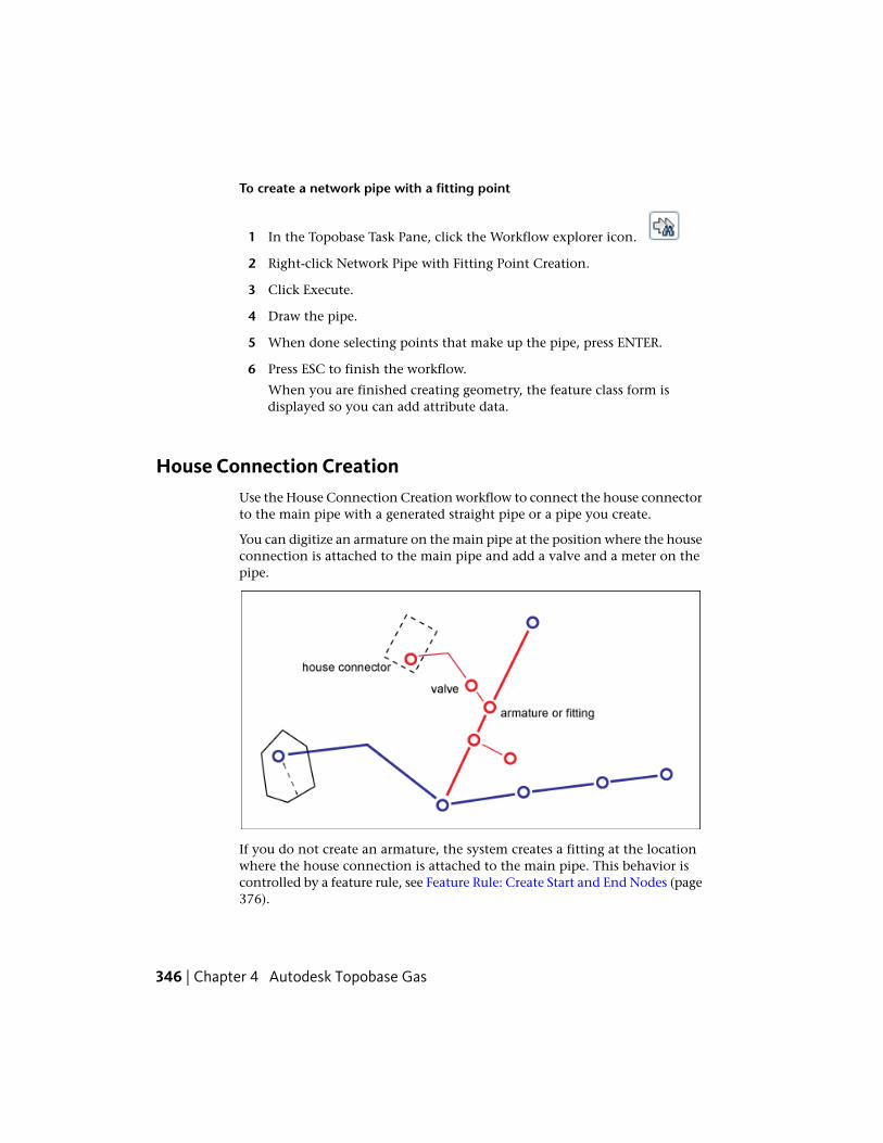
To create a network pipe with a fitting point
1 In the Topobase Task Pane, click the Workflow explorer icon.
2 Right-click Network Pipe with Fitting Point Creation.
3 Click Execute.
4 Draw the pipe.
5 When done selecting points that make up the pipe, press ENTER.
6 Press ESC to finish the workflow.
When you are finished creating geometry, the feature class form isdisplayed so you can add attribute data.
House Connection CreationUse the House Connection Creation workflow to connect the house connectorto the main pipe with a generated straight pipe or a pipe you create.
You can digitize an armature on the main pipe at the position where the houseconnection is attached to the main pipe and add a valve and a meter on thepipe.
If you do not create an armature, the system creates a fitting at the locationwhere the house connection is attached to the main pipe. This behavior iscontrolled by a feature rule, see Feature Rule: Create Start and End Nodes (page376).
346 | Chapter 4 Autodesk Topobase Gas

To create a house connection
1 In the Topobase Task Pane, click the Workflow explorer icon.
2 Right-click House Connection Creation.
3 Click Execute.
4 Specify a reference record, if any.
5 Under Pipe from House Connector to Main Pipe, select Straight Pipe orDigitize Pipe.
If you choose Straight Pipe you are prompted to select the main pipe inthe drawing. The connection is created as an orthogonal projection onthe main pipe.
6 Specify whether to add an armature, a valve or a meter on the main pipe.
If you choose Armature and Straight Pipe the armature is createdautomatically.
7 Click OK.
8 Follow the prompts.
9 Press ESC to finish the workflow.
When you are finished creating geometry, the feature class form isdisplayed so you can add attribute data.
See also:
■ House Connector (page 395)
Site or Facility CreationUse the Site or Facility Creation workflow to create a site that can be connectedto a network point or to create a facility structure with geometry.
To create a site or facility
1 In the Topobase Task Pane, click the Workflow explorer icon.
2 Right-click Site or Facility Creation.
Acquisition Workflows | 347
3 Click Execute.
4 In the Workflows pane, click Site or Facility (With Structure).
5 Specify a reference record, if any.
6 Click a geometry type for the site or facility, either point, line, or polygon.
7 Click OK.
8 Follow the prompts.
9 Press ESC to finish the workflow.
When you are finished creating geometry, the feature class form isdisplayed so you can add attribute data.
See also:
■ Site (page 405)
■ Facility (page 384)
■ Facility Creation (page 348)
Facility CreationUse the Facility Creation workflow to either create and name a new structureor add facilities to an existing structure. Facilities are not related to networkpoints or lines.
To create a facility
1 In the Topobase Task Pane, click the Workflow explorer icon.
2 Right-click Facility Creation.
3 Click Execute.
4 Under Structure Of The Facility, select the structure to add facilities to orenter a name for a new structure.
5 Select the type of geometry you want to create.
6 Click OK and follow the prompts.
7 Press ESC to finish the workflow.
348 | Chapter 4 Autodesk Topobase Gas
When you are finished creating geometry, the feature class form isdisplayed so you can add attribute data.
The facility includes a new structure (if selected), a new facility attributefeature, and a facility geometry feature of the selected geometry type.
8 In the Facility feature class form, define the facility attributes for thecreated features.
The facility geometry feature class is not displayed, because it does notstore any special attributes.
9 Double-click the FID Structure attribute to open the Structure featureclass form.
This is the structure associated with the facility.
Add Geometry and Equipment
With the initial Facility Creation workflow you can create a facility with onegeometry feature. You can add more geometries and equipment features.
To add geometry and equipment
1 In the Facility feature class form, select the facility.
2 Click Equipment to show the Equipment feature class form. If noequipment has been created so far, the filter is empty.
3 On the form toolbar, click the New Record icon. Note that the FID of thefacility has been inserted.
4 Adjust the attributes and click OK.
Repeat these steps to add more geometry features to the facility.
5 Click Facility Line to open the related feature class form. The filter showsall lines that are related to the current facility.
6 On the form toolbar, click Digitize New Feature. Follow the prompts.
See also:
■ Facility (page 384)
Acquisition Workflows | 349

Damage CreationUse the Damage Creation workflow to place a damage point feature on a pipe.Optionally, you can create an armature such as a strap at the damage location.If you create an armature, the pipe is soft split.
Damage points can only be placed on a pipe.
To create a damage point feature
1 In the Topobase Task Pane, click the Workflow explorer icon.
2 Right-click Damage Creation.
3 Click Execute.
4 Specify whether to add an armature at the location of the damage.
5 Click OK.
6 Follow the prompts.
7 Press ESC to finish the workflow.
When you are finished creating geometry, the feature class form isdisplayed so you can add attribute data.
See also:
■ Damage Point (page 390)
Pressure Zone CreationUse the Pressure Zone Creation workflow to create pressure zones thatsubdivide the gas network into sections of similar pressure.
To create a pressure zone
1 In the Topobase Task Pane, click the Workflow explorer icon.
2 Right-click Pressure Zone Creation.
3 Click Execute.
4 Follow the prompts to create one or more pressure zones.
350 | Chapter 4 Autodesk Topobase Gas

5 Press ESC to finish the workflow.
When you are finished creating geometry, the feature class form isdisplayed so you can add attribute data.
NOTE With the SetPressureZone feature rule you can control the assignment ofpressure zones to network objects, see Feature Rule: Set Pressure Zone (page 373).
See also:
■ Pressure Zone (page 379)
Protection CreationUse the Protection Creation workflow to add casings and/or anodes to a pipe.
To create a protection casing or anode
1 In the Topobase Task Pane, click the Workflow explorer icon.
2 Right-click Protection Creation.
3 Click Execute.
4 Select a pipe.
5 Under Choose Protections, click casings, anodes, or both.
6 Click OK to start digitizing one or more casings (closed polylines).
7 Press ESC to finish digitizing casings.
8 If selected, you are now prompted to create anodes. Create as many anodesas needed.
9 Press ESC to finish the workflow.
When you are finished creating geometry, the feature class form isdisplayed so you can add attribute data.
See also:
■ Protection (page 403)
Acquisition Workflows | 351

Administrative Information CreationUse the Administrative Information Creation workflow to acquireadministrative information, such as contacts, locations, supply zones, pressurezones, meter zones or manufacturers.
To create administrative information
1 In the Topobase Task Pane, click the Workflow explorer icon.
2 Right-click Administrative Information Creation.
3 Click Execute.
4 Specify which kind of information you want to acquire.
5 Click OK to start digitizing or entering the data.
See also:
■ Contact (page 377)
■ Location (page 378)
■ Manufacturer (page 378)
■ Meter Area (page 378)
■ Pressure Zone (page 379)
■ Supply Zone (page 380)
Analysis WorkflowsAnalysis workflows and rules allow designers to trace a gas network from oneor more designated start features to an optional stop feature. Network tracingbegins from the start location and stops when all stop features have beenreached. You can also set attribute-dependent stop conditions, locate pointobjects on a pipe, locate point objects that are not connected to the network,or pinpoint error in a network topology.
352 | Chapter 4 Autodesk Topobase Gas

Find ConnectedTrace a gas network from a start feature to one or more optional stop features.The network is traced from the start feature to the stop features, if stop featuresare specified
TIP Network tracing is much more efficient when start and stop features areselected. Tracing a network without selecting a stop feature can take a very longtime.
To find connected pipes
1 In the Topobase Task Pane, click the Workflow explorer icon.
2 Right-click Find Connected.
3 Click Execute.
4 In the Workflow pane, under Choose A Start Feature, do the following:
■ Click Choose.
■ Click one or more features at the start of the network trace.
■ Press ENTER to complete the selection.
5 If you do not want to trace the whole network, do the following:
■ Under Optionally Choose Stop Features, click Choose.
■ Click one or more stop features.
■ Press Enter to complete selection.
6 Under Options, select Include Stop Features to list all connected featuresincluding the stop features. If this check box is cleared, stop features arenot included.
Start features are always included in the list of connected features.
7 To specify the trace direction, click Forward, Backward, or Both.
8 Click OK to start network tracing.
When network tracing has finished, all connected features are displayedin the feature explorer in the Workflows pane. Use the tools at the topof the Workflows pane to open the feature class form, highlight selectedfeatures, and zoom to selected features.
Analysis Workflows | 353

See also:
■ Adapting a Viewport for Feature Highlighting in the Topobase Client UserGuide
Find Connected with Stop ConditionsThe Find Connected With Stop Condition workflow provides the samefunctionality as the Find Connected workflow. In addition, you can definestop features based on their attributes.
All advanced stop conditions that have been defined in the data modeladministrator are also available here.
For more information about stop conditions using SQL statements, see NetworkTracer in the Topobase Administrator Guide.
To trace connected pipes using a stop condition
1 In the Topobase Task Pane, click the Workflow explorer icon.
2 Right-click Find Connected With Stop Conditions.
3 Click Execute.
4 In the Workflow group, under Choose a Start Feature, do the following:
■ Click Choose.
■ Click one or more features at the start of the network trace.
■ Press ENTER to complete selection.
5 If you do not want to trace the whole network, do the following:
■ Under Optionally Choose Stop Features, click Choose.
■ Click one or more stop features.
■ Press ENTER to complete selection.
6 Under Options, select Include Stop Features to list all connected featuresincluding the stop features. If this check box is cleared, stop features arenot included.
Start features are always included in the list of connected features.
354 | Chapter 4 Autodesk Topobase Gas

7 To specify the trace direction, click Forward, Backward, or Both.
8 Under Stop Conditions, click Add.
9 In the Stop Condition Editor dialog box, do one of the following:
■ Select an existing stop condition.
■ Click New and define a new stop condition.To learn about creating a new stop condition, see Stop ConditionEditor.
10 Click OK to close the Stop Condition Editor dialog box.
11 Click OK to start network tracing.
When network tracing has finished all connected features are displayedin the feature explorer in the Workflow pane. Use the tools at the top ofthe Workflow pane to open the feature class form, highlight selectedfeatures, and zoom to selected features.
In the Stop Condition Editor dialog box, the list displays only the stopconditions that are not assigned to any tracing template.
See also:
■ Adapting a Viewport for Feature Highlighting in the Topobase Client UserGuide
Find Non Split Point on PipeUse Find Non Split Point On Pipe to find all points on a pipe that are not split.
Finding non split points on a pipe
1 In the Topobase Task Pane, click the Workflow explorer icon.
2 Right-click Find Non Split Point On Pipe.
3 Click Execute.
4 Select the point feature classes to locate.
Select All to search for non split points of any feature class.
Analysis Workflows | 355

5 To perform the search on a specific set of features, click Choose and clickthe point features.
6 Click OK.
When the search has finished, all non split points are displayed in the featureexplorer in the Workflow pane. Use the tools at the top of the Workflow paneto open the feature class form, highlight selected features, to zoom to selectedfeatures, and to soft or hard split the pipes.
See also:
■ Adapting a Viewport for Feature Highlighting in the Topobase Client UserGuide
Cable Acquisition WorkflowsUse Cable Acquisition workflows to create control cables or control pointsthat contain information about wires, cables, and electronic system controlsthat are deployed throughout the gas utility network. For more information,see Control Cable (page 383).
Control Cable CreationUse the Control Cable Creation workflow to create a cable used to transmitelectricity or information to system controls.
To create a control cable
1 In the Topobase Task Pane, click the Workflow explorer icon.
2 Right-click Control Cable Creation.
3 Click Execute.
4 Follow the prompts to create one or more control cables.
5 When done selecting points that make up the control cables, press ENTER.
6 Press ESC to finish the workflow.
When you are finished creating geometry, the feature class form isdisplayed so you can add attribute data.
356 | Chapter 4 Autodesk Topobase Gas

If you create a control cable with a start or end that is not connected to anetwork point, a cable point is created. This is controlled by a feature rule;see Feature Rule: Create Start and End Nodes (page 376).
Control Point CreationUse the Control Point Creation workflow to create control cable points.Optionally, you can choose to connect the control cable points to a site, oryou can digitize control cabinets.
1 In the Topobase Task Pane, click the Workflow explorer icon.
2 Right-click Control Point Creation.
3 Click Execute.
4 Specify a reference record, if any.
5 Specify whether to connect the points to a site.
6 Specify whether to create control cabinets.
7 Click OK.
8 Follow the prompts to create one or more control points.
9 Press ESC to finish the workflow.
When you are finished creating geometry, the feature class form isdisplayed so you can add attribute data.
See also:
■ Site (page 405)
Report WorkflowsReport workflows are used to generate predefined or user-defined reports.Designers can quickly and easily generate reports from a list of predefinedreport templates. These reports include:
DescriptionPredefined Report
Shows a complete list of all feature classesand features in the gas database. It also
Data Model Description
Report Workflows | 357

DescriptionPredefined Report
shows the number of features for eachfeature class and how they are linked toother tables (according to the meta-tableTB_RELATIONS).
Displays statistical information about pointand pipe information, lists other features,and provides a count.
Gas Network Statistics
Only if the COGO extension is available.COGO reports
The report templates have been created with the Topobase Report Designer.For more information, refer to Report Designer Introduction in the TopobaseAdministrator Guide.
Report GenerationUse the Report Generation workflow to print reports. The report templatesare created by your Topobase Administrator using the Topobase ReportDesigner.
To generate reports
1 In the Topobase Task Pane, click the Workflow explorer icon.
2 Right-click Report Generation.
3 Click Execute.
4 In the Workflows group, select a report name and click OK.
The report is displayed in a secondary window. You can print the reportor change its format to HTML, ASCII, or PDF.
Managing Gas Network TopologiesAutodesk Topobase uses topologies to model objects and phenomena of thereal world. Typically, a GIS user needs information about relationships betweenobjects with topological characteristics. Models of land and other flat surfaces
358 | Chapter 4 Autodesk Topobase Gas

is a perfect application for area topology. Logical topology is appropriatewherever real world objects are connected to each other in networks.
Topobase Gas is based on the utility model and network topology which isused for network tracing.
For more information about defining and managing topologies, refer toTopology Introduction in the Topobase Administrator Guide.
Check TopologiesUse the Topology Checker to locate errors in a network topology.
To check a topology for errors
1 Click the Document explorer icon.
2 Expand the Topologies listing and right-click the topology. Click TopologyChecker.
Topology errors are displayed in the Logical Topology Checker Desktopdialog box.
3 Navigate the tree view to select specific features.
4 Use the Topology Checker tools to perform the following operations onselected features:
■ Refresh the topology check after you have addressed problems.
■ Open the feature class form.
■ Highlight a feature or clear all highlighted features.
■ Zoom to a selected feature in the map.
■ Delete a selected feature.
Check Topologies | 359

See also:
■ Gas Topologies (page 409)
Explore Stop ConditionsNetwork topologies contain predefined stop conditions. You can view themwith the Topobase Administrator.
To explore stop conditions
1 Start Topobase Administrator and open the Gas workspace.
2 Click Document menu ➤ Data Model to select the document.
3 In the data model explorer, expand Topologies.
4 Expand a topology and expand the Conditions folder.
5 Right-click the stop condition you want to view and click Properties.
The Tracing Condition dialog box is displayed.
6 View or edit the setting for the stop condition or click Cancel to exit.
See also:
■ Stop Condition Editor
For more information about defining conditions, see Network Tracer in theTopobase Administrator Guide.
Use Gas Feature FunctionsEach point and line feature class form provides functions for further processingof the selected records. These functions are available in the Function menuand the Network Tracer menu of the feature classes to which they apply.
To view available functions
1 Click the Document explorer icon.
2 Under Topics, expand a feature. For example, Point.
360 | Chapter 4 Autodesk Topobase Gas

3 Right-click a feature class. For example, Armature.
4 Click Show Form.
5 On the Armature feature class form, do one of the following:
■ Click Function menu ➤ function_name.Where function_name is the name of any function available to theselected feature.
■ Click Network Tracer menu ➤ menufunction_name.
If you start a function from the feature class form, consider the current filter.You can apply the function to all features in the filter or to the current feature.
See also:
■ Point Feature Class Form (page 392)
■ Pipe Feature Class Form (page 387)
Maintenance Record CreationYou can create maintenance records for several feature classes. Use this functionto add maintenance information to a feature. Maintenance information isstored in the Maintenance feature class (GA_MAINTENANCE).
To create a maintenance record
1 Select a feature in your map. For example, an Armature.
2 Right-click the Armature feature and select Attributes.
The Armature feature class form is displayed.
3 On the Armature feature class form, do one of the following:
4 Click Function ➤ Create Maintenance.
The Maintenance feature class form is displayed with a new record.
5 Click the Details tab and enter a maintenance date and maintenanceperiod.
The Next Maintenance Date is automatically calculated based on theentries you make for the maintenance date and maintenance period.
Use Gas Feature Functions | 361

6 Do one of the following:
■ Click Update to accept the entries you made and keep the maintenanceform open for further changes. If no further changes are necessary,close the window.
■ Click Update & Close to accept the entries you made and close themaintenance form.
See also:
■ Maintenance (page 386)
Marker CreationYou can create markers that are assigned to the current feature.
To create a marker
1 Select a feature in your map. For example, a Pipe.
2 Right-click the Pipe feature and select Attributes.
The Pipe feature class form is displayed.
3 Select the features to which you want assign a marker.
4 Click Function menu ➤ Create Marker.
5 Follow the prompts to create the marker.
The Marker feature class form is displayed with a new record.
See also:
■ Marker (page 386)
Show Input and Output PipesFor network points, such as armatures or fittings, you can show connectedinput and output pipes.
To show input or output pipes
1 Select a feature in your map. For example, an Armature.
362 | Chapter 4 Autodesk Topobase Gas
2 Right-click the Armature feature and select Attributes.
The Armature feature class form is displayed.
3 In the Armature feature class form, do one of the following:
■ Click Function menu ➤ Show Input Pipes.
■ Click Function menu ➤ Show Output Pipes.
The related feature class forms are displayed and the input and outputpipes are highlighted in the drawing.
See also:
■ Pipe (page 388)
Show Connected PipesFor network points, such as armatures or fittings, you can show connectedinput pipes.
To show connected pipes
1 Select a feature in your map. For example, an Armature.
2 Right-click the Armature feature and select Attributes.
The Armature feature class form is displayed.
3 Click Function menu ➤ Show Connected Pipes.
The related feature class forms are opened and the pipes are highlightedin the drawing.
See also:
■ Pipe (page 388)
Connect a Point to a SiteUse this function if you have created sites separately from the gas networkand want to associate them.
Use Gas Feature Functions | 363

To connect a point to a site
1 Select a Site feature in your map.
2 Right-click the Site feature and select Attributes.
The Site feature class form is displayed.
3 Click Function menu ➤ Connect Point to Site.
All points that lie inside the site detail polygon are connected.
See also:
■ Site (page 405)
Remove Connections from a SiteYou can remove all connections that are related to a site.
To remove connections from a site
1 Select a Site feature in your map.
2 Right-click the Site feature and select Attributes.
The Site feature class form is displayed.
3 Click Function menu ➤ Remove Site.
Confirm the removal of the site and the record is removed.
See also:
■ Site (page 405)
Network TracerUse the Network Tracer functions to specify start and stop features for networkanalysis.
To specify start and end features for network tracing
1 Select a feature in your map. For example, a Pipe.
2 Right-click the Pipe feature and select Attributes.
364 | Chapter 4 Autodesk Topobase Gas

The Pipe feature class form is displayed.
3 Open the Network Tracer menu do one of the following:
■ Click Set as Start Feature.
■ Click Set as End Feature.
The Network Tracer dialog box is displayed.
4 In the Network Tracer dialog box, open the Tracing Template list andselect a template.
5 Follow the on-screen instructions in the Features section. Depending onthe tracing template, there are various workflows. When you are finished,click Trace.
The resulting features are highlighted in the map and listed in the TracingResult dialog box.
The Tracing Result dialog box displays the features in an explorer tree, fromwhich you can process the features. Expand the items, select a feature and usethe buttons on the toolbar.
To learn more about attributive network topologies, see Creating Topologiesin the Topobase Administrator Guide.
See also:
■ Analysis Workflows (page 352)
Connect Features to a ZoneUse this function to connect features that lie within a pressure zone or a supplyzone. You can use a feature rule to connect the features to the pressure zoneor supply zone.
To connect features to a zone
1 Click the Document explorer icon.
2 Expand the Administration topic and do one of the following:
■ Right-click Pressure Zone.
■ Right-click Supply Zone.
Connect Features to a Zone | 365
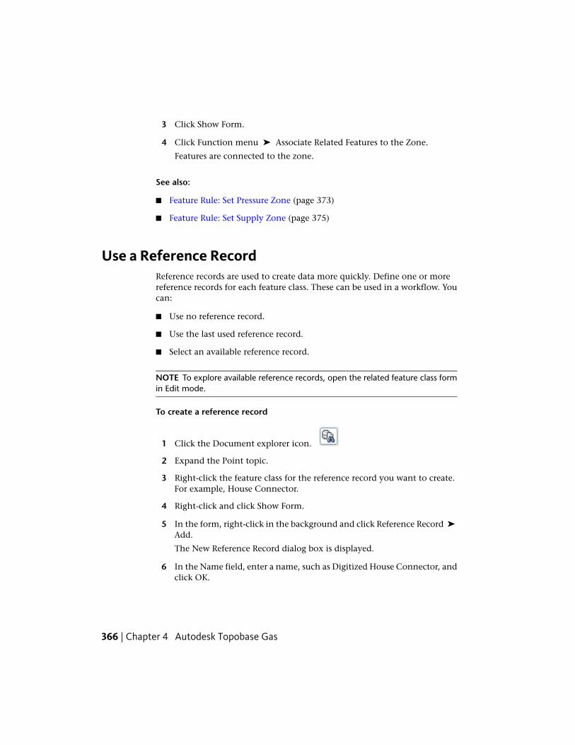
3 Click Show Form.
4 Click Function menu ➤ Associate Related Features to the Zone.
Features are connected to the zone.
See also:
■ Feature Rule: Set Pressure Zone (page 373)
■ Feature Rule: Set Supply Zone (page 375)
Use a Reference RecordReference records are used to create data more quickly. Define one or morereference records for each feature class. These can be used in a workflow. Youcan:
■ Use no reference record.
■ Use the last used reference record.
■ Select an available reference record.
NOTE To explore available reference records, open the related feature class formin Edit mode.
To create a reference record
1 Click the Document explorer icon.
2 Expand the Point topic.
3 Right-click the feature class for the reference record you want to create.For example, House Connector.
4 Right-click and click Show Form.
5 In the form, right-click in the background and click Reference Record ➤
Add.
The New Reference Record dialog box is displayed.
6 In the Name field, enter a name, such as Digitized House Connector, andclick OK.
366 | Chapter 4 Autodesk Topobase Gas

7 In Reference Record mode, enter the reference values to be used, such asAccuracy = Digitized.
8 Click Save.
For more information about reference records, see Using Reference Recordsin the Topobase Client User Guide.
Split LinesIf you place a point feature on a line or polyline feature, the line or polylineis split to preserve a correct network topology.
To digitize a point and split a line
1 Click the Document explorer icon.
2 Expand the topic for the line you want to split. For example, Pipe.
3 Right-click the Pipe feature class and do one of the following:
■ Click Soft Split (Only Geometry)
■ Click Hard Split (Also Attributes)
4 In the drawing, select the line representing the pipe.
5 In the Select dialog box, select the point feature class you want to digitize.For example, select Meter.
6 Digitize the point.
The new point does not need to lie exactly on the selected line. If thepoint lies next to the line, the line is split and the new lines move to thepoint. However, if the point lies on a line that is not the selected one, nosplitting is performed.
NOTE Use Object Snap and Object Snap Tracking to ensure that the point isplaced on the line. For more information, refer to AutoCAD Help.
Split Lines | 367

Splitting lines: When you digitize a point on a utility line or next to a utility line, thenew lines move to the point.
When a pipe is digitized, normally only the start and the endpoint coordinatesare known, and connected using a straight line. Then, when a new point ismeasured, such as a house connector, this point normally does not lie exactlyon the pipe, and the pipe must be adjusted to this new point.
Soft Split and Hard SplitBecause geometry and attributes are stored separately, one geometry featureclass such as a point, can represent various attribute feature classes such asarmature and fitting. For line features, there are two different line splittingmethods: soft split and hard split.
368 | Chapter 4 Autodesk Topobase Gas

Gas data model: Relation between pipe and line feature class
In a workflow you can specify whether the line is soft split or hard split. Thisdetermine how the system handles the attribute data of the two resultingfeatures.
DescriptionSplit Type
With soft split, the line is split into twoseparate features. Each has its own geo-
Soft Split
metry (GA_LINE), but they both use thesame attribute data (GA_PIPE).Use soft split for point features of minorimportance and when the attributes of thepipe do not change, such as armatures.
With hard split, the line is split into twoseparate features. Each has its own geo-
Hard Split
metry (GA_LINE) and each has its own at-tribute data (GA_PIPE).Use hard split for point features of majorimportance, such as a pump or a valve.Use hard split if the attributes of the pipechange, such as diameter, material, ormodel.
Split Lines | 369
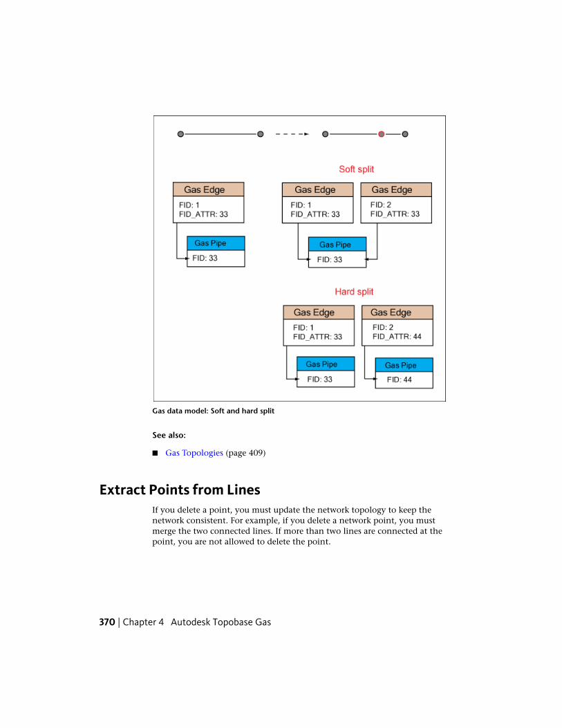
Gas data model: Soft and hard split
See also:
■ Gas Topologies (page 409)
Extract Points from LinesIf you delete a point, you must update the network topology to keep thenetwork consistent. For example, if you delete a network point, you mustmerge the two connected lines. If more than two lines are connected at thepoint, you are not allowed to delete the point.
370 | Chapter 4 Autodesk Topobase Gas

To extract a point
1 Click the Document explorer icon.
2 Right-click the point feature class and click Extract From Line.
3 When prompted, click the point you want to delete.
The point is deleted from the database and the connected lines aremerged.
Network topology: Extracting points from a network line
See also:
■ Gas Topologies (page 409)
Extract Points from Lines | 371

Organization of Gas Functions and FeaturesWhen you run Data Acquisition workflows in the Gas application, thefollowing feature rules improve the efficiency of adding features and keepdata consistent.
■ Soft split — If a network line has a network point on a vertex, the line issplit.
■ Point orientation — If you place a point on a pipe, the symbol is orientedaccording to the direction of the pipe.
■ Move — If a pipe is moved, the connected pipe and points also move.
■ Identical points — Ensure that no gas network points or cable controlpoints are created in the same location. See the Topobase Feature Rulereference, section GA_RejectDuplicatePoints_BIU.
■ Pressure zone — Enable or disable the pressure zone rule for a feature if itis located within a zone. See Feature Rule: Set Pressure Zone (page 373).
■ Supply zone — Enable or disable the supply zone rule for a feature if it islocated within a zone. See Feature Rule: Set Supply Zone (page 375).
■ Compute maintenance — Compute maintenance dates based on currentmaintenance dates and maintenance periods. See the Topobase FeatureRule reference, section GA_ComputeNextMaintDate_BIU.
For more information about feature rules, see About Feature Rules in theTopobase Administrator Guide.
See also:
■ Split Lines (page 367)
■ Pressure Zone (page 379)
■ Supply Zone (page 380)
Explore Gas Feature RulesMany feature classes in the gas data model are comprised of feature rules. Usethe data model administrator to view, enable, or disable feature rules.
372 | Chapter 4 Autodesk Topobase Gas

To explore gas feature rules
1 Start Topobase Administrator and open the Gas workspace.
2 Click Document menu ➤ Data Model.
3 Expand a topic in the data model explorer.
4 Right-click a feature class and click Edit Feature Rules.
The Feature Rules Properties dialog box is displayed.
5 In the Feature Rules Properties dialog box, click the Client Side (.NET)tab.
6 In the Applied Rule Bases list, enable or disable the rules you wantadjusted.
7 Click Save & Close.
See also:
■ Organization of Gas Functions and Features (page 372)
For more information about feature rules, see About Feature Rules in theTopobase Administrator Guide.
Feature Rule: Set Pressure ZoneWhen you digitize gas network features, a feature rule sets the pressure zonefor a feature if it is located within a zone. If the feature is located in overlappingzones, you are prompted to select a zone. If you select Yes, you can select azone. If you select No, the pressure zone value is cleared.
NOTE If you digitize a pressure zone while the gas network features already exist,the pipes are not updated and do not belong to the pressure zone.
You can use a feature function to update the relations. See also ConnectFeatures to a Zone (page 365)
To activate the Set Pressure Zone feature rule (Line feature class)
1 Start Topobase Administrator and open the Gas workspace.
2 Click Document menu ➤ Data Model.
3 Expand the Utility topic and select the Line feature class (GA_LINE).
Explore Gas Feature Rules | 373
4 Right-click and click Edit Feature Rules.
The Feature Rules Properties dialog box is displayed.
5 In the Feature Rules Properties dialog box, click the Client Side (.NET)tab.
6 In the Applied Rule Bases list, enable the GA_SetPressureZone_BIU andthe GA_SetPressureZone_AIU rules.
7 Click Save & Close.
To apply the Set Pressure Zone feature rule (Point feature class)
1 Start Topobase Administrator and open the Gas workspace.
2 Click Document menu ➤ Data Model.
3 Expand the Point topic and select the feature class. For example, Fitting(GA_FITTING).
4 Right-click and click Edit Feature Rules.
The Feature Rules Properties dialog box is displayed.
5 In the Feature Rules Properties dialog box, click the Client Side (.NET)tab.
6 In the Applied Rule Bases list select the GA_SetPressureZone_BI rule.
7 Click Save & Close.
To activate the Set Pressure Zone feature rule (Pipe feature class)
1 Start Topobase Administrator and open the Gas workspace.
2 Click Document menu ➤ Data Model.
3 Expand the Pipe topic and select the Pipe feature class (GA_PIPE).
4 Right-click and click Edit Feature Rules.
The Feature Rules Properties dialog box is displayed.
5 In the Feature Rules Properties dialog box, click the Client Side (.NET)tab.
6 In the Applied Rule Bases list, select the GA_SetPressureZone_BI rule.
7 Click Save & Close.
374 | Chapter 4 Autodesk Topobase Gas

See also:
■ Pressure Zone (page 379)
■ GA_SetPressureZone_BI
■ GA_SetPressureZone_BIU rule group
Feature Rule: Set Supply ZoneWhen you digitize gas network features, a feature rule sets the supply zonefor a line feature if it is located within a zone. If the feature is located inoverlapping zones, you are prompted to select a zone. If you select Yes, youcan select a zone. If you choose No, the pressure zone value is cleared.
NOTE If you digitize a supply zone while the gas network features already exist,the pipes are not updated and do not belong to the supply zone.
You can use a feature function to update the relations. See also ConnectFeatures to a Zone (page 365)
To activate the Set Supply Zone feature rule (Line feature class)
1 Start Topobase Administrator and open the Gas workspace.
2 Click Document menu ➤ Data Model.
3 Expand the Utility topic and select the Line feature class (GA_LINE).
4 Right-click and click Edit Feature Rules.
The Feature Rules Properties dialog box is displayed.
5 In the Feature Rules Properties dialog box, click the Client Side (.NET)tab.
6 In the Applied Rule Bases list, enable the GA_SetSupplyZone_BIU andthe GA_SetSupplyZone_AIU rules.
7 Click Save & Close.
To activate the Set Supply Zone feature rule (Pipe feature class)
1 Start Topobase Administrator and open the Gas workspace.
2 Click Document menu ➤ Data Model.
Explore Gas Feature Rules | 375

3 Expand the Pipe topic and select the Pipe feature class (GA_PIPE).
4 Right-click and click Edit Feature Rules.
The Feature Rules Properties dialog box is displayed.
5 In the Feature Rules Properties dialog box, click the Client Side (.NET)tab.
6 In the Applied Rule Bases list, select the GA_SetSupplyZone_BI rule.
7 Click Save & Close.
See also:
■ Supply Zone (page 380)
Feature Rule: Create Start and End NodesThe CreateStartEndNode feature rule controls the automatic creation ofnetwork points.
If you create a pipe with a start or end that is not connected to a networkpoint, a fitting is created. Sometimes the gas network does not continue beyonda certain point. If you need to create non-ending pipes, you can disable thisfeature rule. Also, you can configure the feature rule, so that a network pointof any type is created.
If you create a control cable with a start or end that is not connected to anetwork point, a cable point is created.
To enable or disable the CreateStartEndNode feature rule for pipes
1 Start Topobase Administrator and open the Gas workspace.
2 Click Document menu ➤ Data Model.
3 Expand the Utility topic and select the Line feature class (GA_LINE).
4 Right-click and click Edit Feature Rules.
The Feature Rules Properties dialog box is displayed.
5 In the Feature Rules Properties dialog box, click the Client Side (.NET)tab.
6 In the Applied Rule Bases list, select or deselect the CreatetStartEndNoderule and click Edit.
376 | Chapter 4 Autodesk Topobase Gas
The Edit Rule Base dialog box is displayed.
7 In the Edit Rule Base dialog box, do the following:
■ Select or clear the Active option.Optionally, you can also enable or disable the feature rule in theFeature Rules Properties dialog box.
■ In the Parameters field, specify which point feature class to create.For example, GA_FITTING.
■ Click OK.
8 Click Save & Close.
See also:
■ Network Pipe Creation (page 344)
■ Control Cable Creation (page 356)
■ CreateStartEndNode
AdministrationThese attribute feature classes manage contacts, customers, locations,manufacturers, and item models.
In addition, the Administration topic includes feature classes for meter areas,pressure zones, protection zones, and supply zones.
ContactThis feature class manages contact information, such as company address,contact name, and email.
DescriptionContact
AdministrationTopic
GA_CONTACTTable name
You can access the contact form from most of the feature class forms using arelation.
Administration | 377

In the contact form, you can access several gas network features using the linkbuttons in the Related Tables tab.
LocationThis feature class groups gas utility features by geographical relation.
DescriptionLocation
AdministrationTopic
GA_LOCATIONTable name
ManufacturerUse the Manufacturer feature class to manage the manufacturers of the gasnetwork items.
DescriptionManufacturer
AdministrationTopic
GA_MANUFACTURERTable name
Meter AreaMeter areas are used for visual grouping only.
DescriptionMeter Area
AdministrationTopic
GA_METERAREATable name
Workflow: Administrative InformationCreation. For more information, see Admin-istrative Information Creation (page 352).
Shortcut Menu
378 | Chapter 4 Autodesk Topobase Gas
Pressure ZonePressure zones are used to group gas utility items.
DescriptionPressure Zone
AdministrationTopic
GA_PRESSUREZONETable name
Workflow: Administrative InformationCreation. For more information, see Admin-istrative Information Creation (page 352).
Shortcut Menu
Feature Rule
Optionally, when digitizing a network feature within an existing area, thefeature is related to the pressure zone. If you digitize a network feature thatlies within several pressure zones, you are prompted to select the zone towhich you want to connect.
This option is controlled by the feature rule SetPressureZone. You can enableor disable this feature rule in the data model administrator. See also FeatureRule: Set Pressure Zone (page 373)
To view related pipes
1 Select the pressure zone in the drawing.
2 Click Home tab ➤ Quick Access panel ➤ Attributes.
3 In the Pressure Zone form, click the Related Tables tab.
4 Click the Pipes (GA_PIPE) referencebutton.
The Pipes form is displayed showing all related pipes in the filter.
See also:
■ Pressure Zone Creation (page 350)
Administration | 379

Supply ZoneSupply zones are used to group gas utility items.
DescriptionSupply Zone
AdministrationTopic
GA_SUPPLYZONETable name
Workflows: Administrative InformationCreation. For more information, see Admin-istrative Information Creation (page 352).
Shortcut Menu
Feature Rule
Optionally, when digitizing a pipe within an existing zone, the pipe is relatedto the supply zone. This is controlled by the feature rule SetSupplyZone. Youcan enable or disable this feature rule in the data model administrator. Seealso Feature Rule: Set Supply Zone (page 375).
Gas Model Feature ClassesFor a large number of feature types, Topobase Gas provides model drivenattributes. You use model tables (*_MODEL) to fill the model driven attributes.Model tables describe several types (models) of a particular network item. Theycan be grouped by manufacturer. Create models for gas network items tosimplify data acquisition.
For example, in a gas utility network with five kinds of valves, you would fillthe model driven attributes using a predifined record from theGA_VALVE_MODEL table. In the Valve feature class form, you use the ModelSelector control to fill in the model field easily.
NOTE In the Model input field, the value Choose Model indicates that you canapply a model. It does not store the model that has been applied, because at anytime you can modify the model driven attributes. The attributes are stored in themain feature class, and you use the model feature class to insert a set of attributes.You can use the model table to store reference values.
380 | Chapter 4 Autodesk Topobase Gas

BEST PRACTICE In the feature class form, use the Model table, to search for anappropriate model. Use the model list, if you are sure which model to use. In theForm Designer, modify the model table form to hide or show model attributes,or to modify the order in the grid. Modify the main feature class form to movethe Model selector to another location.
Usually the model information is created either at the beginning of the projector during data acquisition.
See also Data Model: Model Tables.
The following table is an example of a pipe model table.
GA_PIPE_MODELTable name
Description of DIN/ISO/DVGW/TUEV value.CERTIFICATE
Date when the item was created.DATE_CREATION
Inside diameter of the pipe.DIAMETER_INSIDE
The manufacturer's designated size, ornominal diameter for the subject item,such as 1" gas hydrant, 2" meter, 6" pipe.
DIAMETER_NOMINAL
Outside diameter of the pipe.DIAMETER_OUTSIDE
GA_MANUFACTURERFID_MANUFACTURERManufacturer of this item.
GA_COATING_TBDID_COATING_INSIDE
GA_COATING_TBDID_COATING_OUTSIDE
GA_MATERIAL_TBDID_MATERIAL
A description or other unique informationconcerning the item.
NARRATIVE
The manufacturer's or industry standard'smaximum pressure rating.
PRESSURE_MAX
Thickness of the pipe wall.THICKNESS
Administration | 381

An operator-defined work area. This attrib-ute can be used by the operator for user-
USER_FLAG
defined system processes. It does not affectthe subject item's data integrity and shouldnot be used to store the subject item'sdata.
Name of the model.MODEL_NAME
Short description of the model. This valueis used for the domain table representationof the model.
VALUE
The following table is an example of a valve model table.
GA_VALVE_MODELTable name
Date when the item were created.DATE_CREATION
Dimension 1 of the item.DIMENSION1
Dimension2 of the item.DIMENSION2
GA_MANUFACTURERFID_MANUFACTURER
GA_MATERIAL_TBDID_MATERIAL
GA_VALVE_TYPE_TBDID_TYPEParticular kind, class, or group of valve,such as gate or check.
Model name or number.NAME_NUMBER
A description or other unique information.NARRATIVE
An operator-defined work area. This attrib-ute can be used by the operator for user-
USER_FLAG
defined system processes. It does not affectthe subject item's data integrity and shouldnot be used to store the subject item'sdata.
382 | Chapter 4 Autodesk Topobase Gas

Short description of the model. This valueis used for the domain table representationof the model.
VALUE
Name of the model.MODEL_NAME
Control CableThe control cable feature contains information about wires, cables, andelectronic system controls that are deployed throughout the gas utility network.The control cable feature is where information such as sensory control anddata acquisition (SCADA) on the cable point, control cabinet, and controlcable is stored. It includes the following feature classes:
■ Control cabinet — a cabinet for the cable where electrical nodes are located.
■ Control cable — a cable used to transmit electricity or information tosystem controls.
■ Control cable point — a cable point that represents an electrical node.
The data model for control cables is based on the utility model.
See also:
■ Gas Topologies (page 409)
■ Cable Acquisition Workflows (page 19)
Control CabinetA cabinet for the cable where electrical nodes are located.
DescriptionControl Cabinet
Control CableTopic
GA_C_Control_CabinetTable name
Control Cable | 383

Control CableA cable used to transmit electricity or information to system controls.
DescriptionControl Cable
Control CableTopic
GA_C_CableTable name
Reverse DirectionShortcut menuSoft Split (Only Geometry)Hard Split (Also Attributes)For more information, see Split Lines (page367).Workflows: Control Cable Creation. Formore information, see Control Cable Cre-ation (page 356).
Control Cable PointA cable point that represents an electrical node.
DescriptionControl Cable Point
Control CableTopic
GA_C_Cable_PointTable name
Workflows: Control Point Creation. Formore information, see Control Point Cre-ation (page 357).
Shortcut menu
Extract Points From Lines. For more inform-ation, see Extract Points from Lines (page370).
FacilityTopobase Gas contains a simple data structure for facility management. Youcan use these feature classes to maintain equipment, such as chairs and tables.Facility features are not part of the network topology. They are used fororientation or illustration purposes. The predefined feature classes come with
384 | Chapter 4 Autodesk Topobase Gas
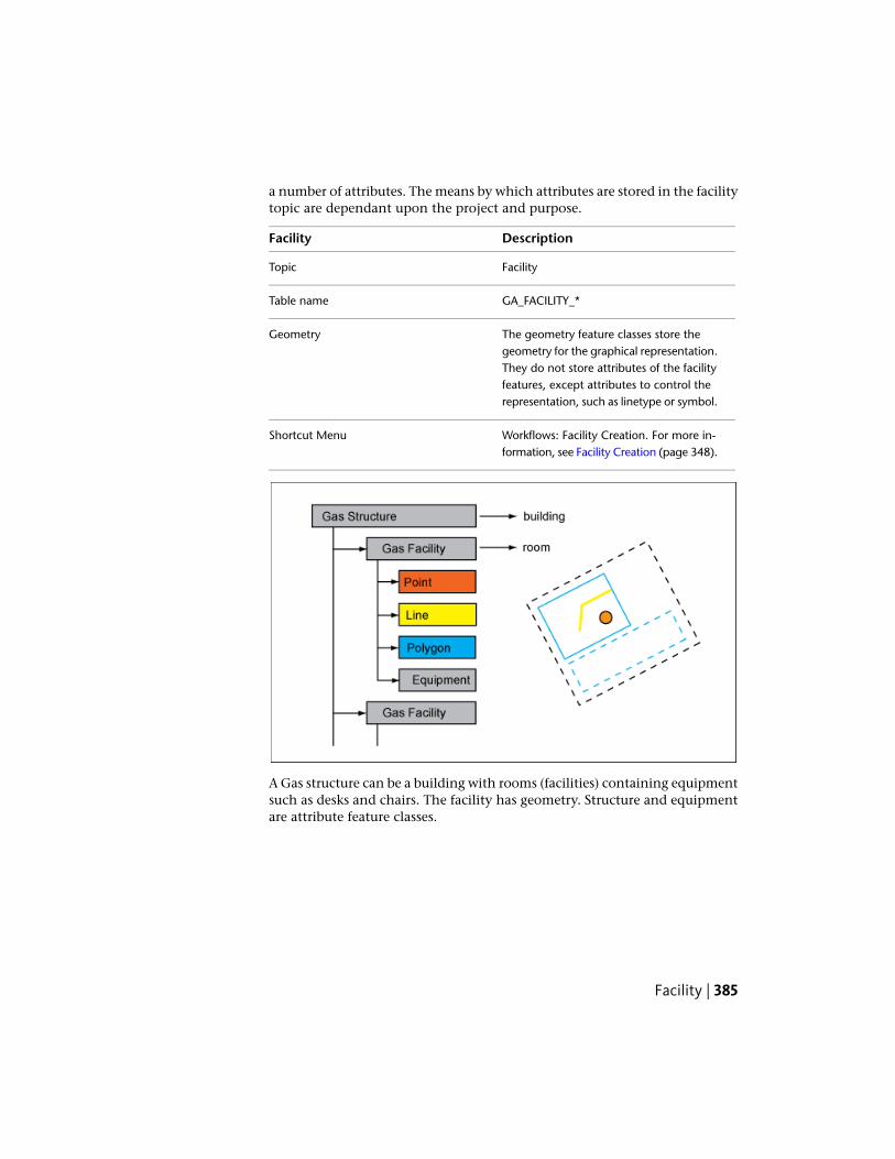
a number of attributes. The means by which attributes are stored in the facilitytopic are dependant upon the project and purpose.
DescriptionFacility
FacilityTopic
GA_FACILITY_*Table name
The geometry feature classes store thegeometry for the graphical representation.
Geometry
They do not store attributes of the facilityfeatures, except attributes to control therepresentation, such as linetype or symbol.
Workflows: Facility Creation. For more in-formation, see Facility Creation (page 348).
Shortcut Menu
A Gas structure can be a building with rooms (facilities) containing equipmentsuch as desks and chairs. The facility has geometry. Structure and equipmentare attribute feature classes.
Facility | 385

Miscellaneous
MaintenanceThis feature class stores information about maintenance work. The featureclass uses the maintenance type domain table. In the basic gas application,this domain table contains only general maintenance types. It can be modifiedto meet the requirements of a customized gas application.
DescriptionMaintenance
MiscellaneousTopic
GA_MAINTENANCETable name
Use the Create Maintenance feature function to create maintenances.
See also:
■ Use Gas Feature Functions (page 360)
■ Maintenance Record Creation (page 361)
MarkerA marker, such as a sign or a concrete monument, is a installed either directlyabove or immediately adjacent to underground lines, bends, or fittings toindicate the presence of gas. Markers are not part of the network topologyand therefore recorded in a common point feature class.
DescriptionMarker
MiscellaneousTopic
GA_MARKERTable name
Use the Create Marker feature function to create markers.
See also:
■ Use Gas Feature Functions (page 360)
■ Marker Creation (page 362)
386 | Chapter 4 Autodesk Topobase Gas

Terrain PointThis feature class stores height points to describe the terrain surface. Terrainpoints can be created during the Network Pipe Creation workflow. For example,they are used to represent the terrain surface in profile drawings.
DescriptionTerrain Point
MiscellaneousTopic
GA_TERRAIN_POINTTable name
terrain heightZ
See also:
■ Network Pipe Creation (page 344)
PipeThe basic gas application contains one gas line feature, pipe. Geometry isstored in the GA_LINE line string feature class. Attribute information is storedin the GA_PIPE attribute feature class.
The pipe feature class has a set of model driven attributes. Values for the modeldriven attributes are stored in the model table (suffix_MODEL). For moreinformation, see Data Model: Model Tables.
Pipe Feature Class FormUse the basic feature class form of the gas pipe to view and edit featureattributes and to view related data.
The pipe feature class form contains the following elements:
■ General tab — Displays general feature information.
■ Details tab — Displays detailed feature attributes and link buttons thatprovide links to all point features the pipe is connected to.
Pipe | 387

■ Related Tables tab — Allows direct access to the following related tables:
Table Name and DescriptionRelated Table
GA_LINE – Contains line geometry.Line
GA_PIPE_TBL – Contains labels for pipe features.Label
GA_MARKER – Contains marker information. Themarker is placed above ground to indicate the positionof a pipe feature.
Marker
GA_ANODE – Contains anode for protection of thepipe.
Anode
GA_CASING – Contains casing for protection of thepipe.
Casing
GA_MAINTENANCE – Contains information about pipemaintenance.
Maintenance
GA_DAMAGE – Contains recorded damage.Damage
■ Table — Displays the attributes in table form.
Some feature class forms provide functions for further processing of the selectedrecords. These functions can be accessed via menus or control buttons. Seealso Use Gas Feature Functions (page 360).
PipePipes are the only standard line feature of a gas utility model.
DescriptionPipe
PipeTopic
GA_PIPETable name
Contains the description of cadastral in-formation.
CADASTRAL_INFO
Elevation relative to the ground.GROUND_ELEVATION
388 | Chapter 4 Autodesk Topobase Gas

DescriptionPipe
Description of the isolation type.ISOLATION
Brief description where the item is located(1m of the wall).
LOCATION
Name or number of the item.NAME_NUMBER
A description or other unique informationconcerning the subject item.
NARRATIVE
Length of the pipe.PIPE_LENGTH
Operating pressure of the item.PRESSURE_OPERATING
Unique serial number of the manufacturer.SERIAL_NUMBER
Slop of the pipe measured by hand. Thisvalue is not calculated.
SLOP_MEASURED
An operator defined work area. This attrib-ute can be used by the operator for user-
USER_FLAG
defined system processes. It does not effectthe subject item's data integrity and shouldnot be used to store the subject item'sdata.
Displays the diameter, length, and materi-al. See Define Labels (page 410).
Label definition
Model driven attributes can either be filledwith the information that is stored in the
Model driven attributes
GA_PIPE_MODEL table, or you can entervalues manually.You use the Model Selector control to se-lect a set of attribute values.See also Gas Model Feature Classes (page380).
Reverse DirectionShortcut MenuSoft Split (Only Geometry)Hard Split (Also Attributes)
Pipe | 389

DescriptionPipe
For more information, see Split Lines (page367).Workflows: Network Pipe Creation. Formore information see, Network Pipe Cre-ation (page 344).Network Pipe With Fitting Point Creation.For more information, see Network Pipewith Fitting Point Creation (page 345).Damage Point Creation. For more inform-ation, see Damage Creation (page 350).Protection Creation. For more information,see Protection Creation (page 351).
See also:
■ Network Pipe Creation (page 344)
■ Network Pipe with Fitting Point Creation (page 345)
Damage PointDamage points indicate locations where damage has occurred. They can berelated to a pipe. They are not part of the network topology.
DescriptionDamage Point
PipeTopic
GA_DAMAGETable name
Workflows: Damage Creation. For moreinformation, see Damage Creation (page350).
Shortcut Menu
PointThe utility points of the gas data model are stored in separate attribute featureclasses, one for each point type. They are grouped in the Point topic.
390 | Chapter 4 Autodesk Topobase Gas

Geometry is stored separately from attribute data. The network point geometryis stored in the Point feature class in the Utility topic. The utility points are:
■ Armature
■ Blow Off Valve
■ Fill
■ Filter
■ Fitting
■ House Connector
■ Light
■ Meter
■ Odor Equipment
■ Pig Launch
■ Pump
■ Regulator
■ Reservoir
■ Sample
■ Shut Off Valve
■ Siphon
■ Source
■ Tank
■ Valve
Each point feature class has a corresponding label feature class (*_TBL) withone default label definition.
Most point feature classes have an associated model table (*_MODEL).Reservoir, House Connector and Source do not have model tables. Modeltables can be found in the Administration topic of the data model, underManufacturer.
Point | 391

See also:
■ Gas Topologies (page 409)
Point Feature Class FormUse the basic feature class forms of the Gas point features to view and editfeature attributes and to view related data.
All point feature class forms contain the following elements:
■ General tab — Displays general feature information.
■ Details tab — Displays detailed feature attributes and link buttons thatprovide links to all line features (usually pipes) the points are connectedto.
■ Related Tables tab — Allows direct access to the following related tables:
Table Name and DescriptionRelated Table
Contains information about network maintenance.Maintenance
Contains marker information. The marker is placed aboveground to indicate the position of a network part.
Marker
Contains label text.Label
Contains point geometry.Point
■ Table tab — Displays all attributes in table form.
Each point feature class form provides functions for further processing of theselected records. These functions can be accessed via menu or control buttons.See also Use Gas Feature Functions (page 360).
Connect Point Features to SitesEach network point can be connected to a site. The easiest way to connect anetwork point to a site is to use the Network Point Creation workflow. Formore information, see Network Point Creation (page 343).
If you have existing points without a site connection, you can assign them toa site.
392 | Chapter 4 Autodesk Topobase Gas

To connect a point to a site
1 Click the Document explorer icon.
2 Right-click the feature class, such as Armature, and click Show Form.
3 Select the armature to connect to the site.
4 Click the Related Tables tab.
5 Click the Point (GA_POINT) referencebutton to show the related geometry feature.
6 In the Point feature class form, click the Details tab.
7 Under Site, select the FID of the related site.
8 Click Update (F5).
For more information about sites, see Site (page 405).
ArmatureAn armature is an assembly that connects pipes.
DescriptionArmature
PointTopic
GA_ARMATURETable name
Workflows: Network Point Creation. Formore information, see Network Point Cre-ation (page 343).
Shortcut Menu
Extract Points From Lines. For more inform-ation, see Extract Points from Lines (page370).
Default label definitions to display thename, the date of creation, and the type.See also Define Labels (page 410).
Label definition
Point | 393

Blow Off ValveA pressure release system using a vacuum-actuated valve designed to releaseexcess pressurized gas into the atmosphere.
DescriptionBlow Off Valve
PointTopic
GA_BLOW_OFF_VALVETable name
Workflows: Network Point Creation. Formore information, see Network Point Cre-ation (page 343).
Shortcut Menu
Extract Points From Lines. For more inform-ation, see Extract Points from Lines (page370).
FillA fill is a location where gas is discharged to users.
DescriptionFill
PointTopic
GA_FILLTable name
Workflows: Network Point Creation. Formore information, see Network Point Cre-ation (page 343).
Shortcut Menu
Extract Points From Lines. For more inform-ation, see Extract Points from Lines (page370).
FilterA filter captures contaminants that might be present in a gas line.
DescriptionFilter
PointTopic
394 | Chapter 4 Autodesk Topobase Gas

DescriptionFilter
GA_FILTERTable name
Workflows: Network Point Creation. Formore information, see Network Point Cre-ation (page 343).
Shortcut Menu
Extract Points From Lines. For more inform-ation, see Extract Points from Lines (page370).
FittingA fitting is used to connect, cap, or plug a pipe carrying gas.
DescriptionFitting
PointTopic
GA_FITTINGTable name
Displays the name and number.Label definition
Workflows: Network Point Creation. Formore information, see Network Point Cre-ation (page 343).
Shortcut Menu
Extract Points From Lines. For more inform-ation, see Extract Points from Lines (page370).
House ConnectorA house connector is a service connection point on or inside a building. It isthe last point of a gas network and represents the connection between thenetwork and the consumer/customer.
Use the House Connector Creation workflow to create house connectors withconnecting lines.
DescriptionHouse Connector
PointTopic
Point | 395

DescriptionHouse Connector
GA_HOUSE_CONNECTORTable name
Workflows: Network Point Creation. Formore information, see Network Point Cre-ation (page 343).
Shortcut Menu
House Connection Creation. For more in-formation, see House Connection Creation(page 346)Extract Points From Lines. For more inform-ation, see Extract Points from Lines (page370).
Manage Customer Information
The GA_HOUSE_CONNECTOR table has a Customer Number attribute.However, there is no table for managing customer information becausecustomers often use external software (for example SAP) for this.
To manage customer information within Topobase, use the data modeladministrator to create the appropriate feature classes.
To manage customer information
1 Create a new Customer feature class in the Administration topic.
2 Add attributes as needed, such as Name, Address, Telephone, and E-mail.
3 Customize the feature class form using the Form Designer.
4 In the House Connector form, add a Basic ComboBox control forCustomer Number and create the relation to the newly created tablecontaining the customers.
For more information, see the Setting Up Topobase in the TopobaseAdministrator Guide.
Generate Customer Notifications
Topobase Gas helps you generate notification letters regarding planned workor interruptions in the gas network. For example, if a pipe has a defect andthe gas must be stopped, you might do a network tracing to find all houseconnectors so you can notify customers.
396 | Chapter 4 Autodesk Topobase Gas

There are several ways to generate customer notification letters.
■ Use the Topobase Report Designer.For more information about the Topobase report designer, see the ReportDesigner Introduction in the Topobase Administrator Guide.
■ Use Topobase Client to export to Microsoft® Word.
■ Export the data to any format and use external software to generate letters.For example, export a customer list to Microsoft® Excel®.
LightUse this feature class for the graphical representation of the location of a gaslight fixture. A gas light fixture utilizes gas as its energy source and containsa flame used for illumination of an area.
PointTopic
GA_LIGHTTable name
Workflows: Network Point Creation. Formore information, see Network Point Cre-ation (page 343).
Shortcut Menu
Extract Points From Lines. For more inform-ation, see Extract Points from Lines (page370).
MeterA meter is a device installed in a line for measuring the quantity and rate ofgas flowing to a facility or through a section of line.
DescriptionMeter
PointTopic
GA_METERTable name
Workflows: Network Point Creation. Formore information, see Network Point Cre-ation (page 343).
Shortcut Menu
Point | 397

DescriptionMeter
Extract Points From Lines. For more inform-ation, see Extract Points from Lines (page370).
You can use the related feature class GA_MAINTENANCE to create events suchas meter readings, installation, mounting, or calibration. For more information,see Maintenance (page 386).
Odor EquipmentThis is equipment located the a control station that allows the addition of anodorant to a gas. An odorant provides a characteristic “warning” smell.
DescriptionOdor Equipment
PointTopic
GA_ODOUR_EQUIPMENTTable name
Workflows: Network Point Creation. Formore information, see Network Point Cre-ation (page 343).
Shortcut Menu
Extract Points From Lines. For more inform-ation, see Extract Points from Lines (page370).
Pig LaunchA pig launch is a point where a pigging device is inserted to clean up a pipefitting.
DescriptionPig Launch
PointTopic
GA_PIG_LAUNCHTable name
Workflows: Network Point Creation. Formore information, see Network Point Cre-ation (page 343).
Shortcut Menu
398 | Chapter 4 Autodesk Topobase Gas

DescriptionPig Launch
Extract Points From Lines. For more inform-ation, see Extract Points from Lines (page370).
PumpA pump is a mechanical device for a gas system that draws material into itselfthrough an entrance port and forces the material out through an exhaust port.
DescriptionPump
PointTopic
GA_PUMPTable name
Workflows: Network Point Creation. Formore information, see Network Point Cre-ation (page 343).
Shortcut Menu
Extract Points From Lines. For more inform-ation, see Extract Points from Lines (page370).
RegulatorA pressure regulator automatically reduces the pressure on the downstreamside of a valve to a preset magnitude.
DescriptionRegulator
PointTopic
GA_REGULATORTable name
Workflows: Network Point Creation. Formore information, see Network Point Cre-ation (page 343).
Shortcut Menu
Extract Points From Lines. For more inform-ation, see Extract Points from Lines (page370).
Point | 399

ReservoirA reservoir is a body of gas that supplies gas to a gas distribution system.
DescriptionReservoir
PointTopic
GA_RESERVOIRTable name
Workflows: Network Point Creation. Formore information, see Network Point Cre-ation (page 343).
Shortcut Menu
Extract Points From Lines. For more inform-ation, see Extract Points from Lines (page370).
SampleThis feature class stores point locations where one or more gas samples arecollected from a gas utility or system.
DescriptionSample
PointTopic
GA_SAMPLETable name
Workflows: Network Point Creation. Formore information, see Network Point Cre-ation (page 343).
Shortcut Menu
Extract Points From Lines. For more inform-ation, see Extract Points from Lines (page370).
400 | Chapter 4 Autodesk Topobase Gas

Shut Off ValveAn inline valve that cuts or allows the flow of a gas or liquid through the pipeswhere it is installed.
DescriptionShut Off Valve
PointTopic
GA_SHUT_OFF_VALVETable name
Workflows: Network Point Creation. Formore information, see Network Point Cre-ation (page 343).
Shortcut Menu
Extract Points From Lines. For more inform-ation, see Extract Points from Lines (page370).
SiphonA siphon is a continuous tube that allows liquid to flow from a source reservoirto a storage reservoir. By means of a difference in hydrostatic pressure, liquidflows from the end of the tube in the source reservoir through an intermediatepoint that is higher than the source reservoir toward the opposite end of thetube. The opposite end of the tube must be lower than the liquid surface inthe source reservoir.
DescriptionSiphon
PointTopic
GA_SIPHONTable name
Workflows: Network Point Creation. Formore information, see Network Point Cre-ation (page 343).
Shortcut Menu
Extract Points From Lines. For more inform-ation, see Extract Points from Lines (page370).
Point | 401
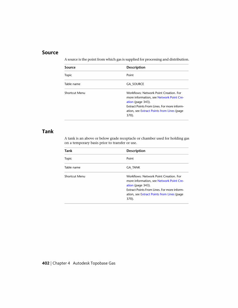
SourceA source is the point from which gas is supplied for processing and distribution.
DescriptionSource
PointTopic
GA_SOURCETable name
Workflows: Network Point Creation. Formore information, see Network Point Cre-ation (page 343).
Shortcut Menu
Extract Points From Lines. For more inform-ation, see Extract Points from Lines (page370).
TankA tank is an above or below grade receptacle or chamber used for holding gason a temporary basis prior to transfer or use.
DescriptionTank
PointTopic
GA_TANKTable name
Workflows: Network Point Creation. Formore information, see Network Point Cre-ation (page 343).
Shortcut Menu
Extract Points From Lines. For more inform-ation, see Extract Points from Lines (page370).
402 | Chapter 4 Autodesk Topobase Gas

ValveA valve is a fitting or device used for shutting or throttling flow through a gasline.
DescriptionValve
PointTopic
GA_VALVETable name
Workflows: Network Point Creation. Formore information, see Network Point Cre-ation (page 343).
Shortcut Menu
Extract Points From Lines. For more inform-ation, see Extract Points from Lines (page370).
ProfileThis topic stores the profile feature classes.
DescriptionFeature Class
Profile system table to store the profileorigin.
TB_PROFILE
Profile system table to store the profile axis.TB_PROFILE_AXIS
Profile feature classes to store the profiledrawing.
GA_xxx_PRO
To create profiles, see Working with Profiles in the Topobase Client User Guide.
ProtectionUse the anode, anode station (point), and casing (polygon) feature classes todisplay and manage gas network protection.
Anodes and casings are usually related to a pipe. The best way to create thesefeature classes is to use the predefined Protection Creation workflow.
Profile | 403

See also:
■ Protection Creation (page 351)
AnodeAn anode is made of a sacrificial material that is more reactive than the materialused to make a cathode (for example, a pipe). The anode is electricallyconnected to the cathode. When an electrical current is passed between theanode and the cathode, the current starts a chemical reaction where the anode,being the more reactive of the two materials, corrodes. This leaves the cathodeundamaged.
DescriptionAnode
ProtectionTopic
GA_ANODETable name
Workflows: Anode Creation. For more in-formation, see Protection Creation (page351).
Shortcut Menu
Network Pipe Creation. For more informa-tion see, Network Pipe Creation (page 344).
Anode StationA central location where anodes are tested for performance in natural gassystems.
DescriptionAnode Station
ProtectionTopic
GA_ANODE_STATIONTable name
404 | Chapter 4 Autodesk Topobase Gas

CasingA casing is a tube which protects cables and/or pipes.
DescriptionCasing
ProtectionTopic
GA_CASINGTable name
Workflows: Casing Creation. For more in-formation, see Protection Creation (page351).
Shortcut Menu
Network Pipe Creation. For more informa-tion see, Network Pipe Creation (page 344).
SiteA site consists of one master attribute feature class with related line, point,and polygon geometry feature classes. Each network point can be connectedto a site. Sites are not part of the network topology. They are a useful meansto group various features of the gas utility network to make them reachable.For example, a site stores house number and location.
DescriptionSite
SiteTopic
GA_SITE_*Table name
Site master feature class that stores the at-tributes.
GA_SITE
Site geometry feature classes. These storethe geometry for graphic presentation and
GA_SITE_LINEGA_SITE_*
normally do not contain any attributes ex-cept graphical attributes like line_type.
Workflow: Site CreationShortcut Menu
The easiest way to connect a network point to a site is to use the NetworkPoint Creation workflow. For more information, see Network Point Creation(page 343).
Site | 405

With the Site or Facility Creation workflow, you can create sites that are relatedto one geometry feature. Add more geometries and equipment features usingthe feature class form. For more information, see Site or Facility Creation (page347) and Facility Creation (page 348).
See also:
■ Connect Point Features to Sites (page 392)
■ Connect a Point to a Site (page 363)
■ Remove Connections from a Site (page 364)
Understand and Work with the Gas Data ModelThe Topobase gas data model consists of the following components:
Feature classesGas Data Model Component
Network geometry is stored in the GA_POINT(for nodes) and GA_LINE (for edges) feature
Network geometry
classes. These feature classes store geometryonly, not attributes. They are related to the gasfeatures for attribute information.The rows of these tables are managed by theUtility API. Do not enhance geometry featureclasses with customer columns.The geometry feature classes build the networktopology.
Network topology is stored in the _NNOD (to-pology nodes) and _NLNK (topology links) fea-tures classes.
Network topology
Only the point feature classes of the Point topicand the pipe feature class of the Pipe topic arepart of the gas network topology.Other feature classes such as the Protection, Site,and Facility topics, the Damage feature class ofthe Pipe topic, are not part of the network topo-logy.
Gas objects are stored in theGA_POINT.FID_ATTR (utility points) and
Gas objects
GA_LINE.FID_ATTR (utility lines) attribute feature
406 | Chapter 4 Autodesk Topobase Gas

Feature classesGas Data Model Component
classes. These have a relation to the associatedpoint or line geometry feature class.
The geometry for control cables is stored in theGA_C_LINE and GA_C_POINT feature classes.
Control cables
Attributes are stored in the GA_C_CABLE andGA_C_CABLE_POINT feature classes.The geometry feature classes build the networktopology.
Model tables store several types of a particularnetwork item. They are located in the Adminis-
Model tables
tration topic under Manufacturer and have thesuffix _MODEL. See also Data Model: ModelTables.
Dimensioning is stored in feature classes withthe suffixes, _L (lines), _P (points), and _HL (helplines).
Dimensioning
Domain tables have the suffix _TBD and containlists of available attribute values for combo boxesin forms.
Domains
Label tables have the suffix _TBL and containfeature labels.
Labels
Client-side feature rules customize Topobasebehavior.
Feature Rules
For more information, see Organization of GasFunctions and Features (page 372).
Understand and Work with the Gas Data Model | 407

Gas data model
For more information about the data model administrator, see the Overviewof Data Model Administrator in the Topobase Administrator Guide.
Explore the Gas Data ModelWith the Data Model Administrator you can explore the data model with itstopics, feature classes, topologies, and utility models.
To explore the Gas data model
1 Start Topobase Administrator and open the Gas workspace.
2 Select the document and click Document menu ➤ Data Model.
3 Use the data model explorer to view feature classes, attributes, labeldefinitions and topologies.
To view the gas document structure version
1 In the data model explorer, right-click the document root node and clickDocument Info.
2 Click the Gas Data Model row.
408 | Chapter 4 Autodesk Topobase Gas

The document structure is shown in the lower information pane.
Gas TopologiesThe Topobase Gas data model contains the following two topologies:
■ Gas network topology — Built from the node feature class GA_POINT andthe edge feature class GA_LINE. A gas point can be related to a site(FID_SITE).
■ Control cable topology — Built from the node feature class GA_C_POINTand the edge feature class GA_C_LINE. A cable point can be related to asite and to a control cabinet (FID_SITE, FID_CONTROL_CABINET).
The node and edge geometry feature classes are stored in the Topology topic.
Topobase Gas network topology. Network points are connected with lines. Networkpoints must not lie on a network line.
Achieving a Valid Network Topology
The topology requires that network points always lie at the start or end of anetwork line. A network point must never lie on a line. If you insert a network
Gas Topologies | 409

point on a network line, the line must be split at the insertion point. Theconsistency of the topology is maintained by feature rules.
If a network point is removed, the connecting lines must be merged.
For more information, see Split Lines (page 367) and Extract Points from Lines(page 370).
For more information about the feature rules, see Organization of GasFunctions and Features (page 372).
Define LabelsThe basic Gas application contains predefined label definitions for most featureclasses. The standard attribute for the label text is called Name Number.
NOTE By default labels are not visible in the drawing. Only labels that are definedas auto labels are created during the create feature operation. Insert labels using
Home tab ➤ Quick Access panel ➤ Create Label.
Example Pipe label — The following label definition is used to display a labelcontaining the diameter, material, and installation date. The label text isqueried from the tables GA_PIPE and GA_MATERIAL_TBD.
select c.value||' '||a.DIAMETER_NOMINAL||' '||to_char(a.date_in
stallation,'YYYY')
from ga_pipe a, ga_material_tbd c
where a.ID_MATERIAL = c.id
and a.FID = $id
Example Armature label — The following label definition is used to displaythe armature type. The label text is queried from the tables GA_ARMATURE,and GA_ARMATURE_TYPE_TBD.
select b.value from ga_armature a, ga_armature_type_tbd b where
a.ID_TYPE = b.ID and a.FID = $id
For more information about defining labels, see the Creating a Label Definitionin the Topobase Administrator Guide.
410 | Chapter 4 Autodesk Topobase Gas

Index
C
classificationwastewater 80
classifywastewater 80
coverheight 335
create featuresgas 342wastewater 68
D
data modelgas 406Topobase Wastewater 111
E
elevationcalculation - wastewater 333
F
facility managementgas 384
feature classesTopobase Wastewater 111
feature ruleselevation (wastewater) 335gas 379Topobase gas 372Topobase Wastewater 111Topobase Water 31
G
gascreate features 342
data model 406feature functions 360label definition 410topology 409workflows 341
H
height-s of wastewater objects 335
I
initiateworkflow 68
L
label definitiongas module examples 410
M
managegas network topologies 358wastewater network topologies 81
N
network analysiswastewater 75
network topologyanalysis workflows 15digitize points 5, 25, 343extract points 29, 370split lines 25, 367
Index | 411

O
optionswastewater - 333
P
pointsextract from lines 29, 370
pressure zone 350gas 377
R
report generationwastewater 79, 357
reportsgas 358wastewater 79water 21
S
split linesgas 367soft and hard split 27, 368water 25
startworkflow 68
supply zonegas 377
T
topologiesmanaging gas network 358managing wastewater network 81
topologygas network 409keep - consistent 370water network 64
W
wastewaterclassification 80create features 68elevation management 335network analysis 75network topology 331report generation 79, 357workflows 67
wastewater options 333water
data model 61feature functions 23introduction 1network topology 64workflows 3
workflowinitiate 68start 68
workflowsgas 341wastewater 67water - 3
412 | Index