Embed Size (px)
Citation preview

Autodesk Medical Center
Page 1
Contents Autodesk Medical Center ........................................ 1
Revit Projects ....................................................... 3
Exercise 1– Create a new project file ............... 3
Datum Elements .................................................. 4
Exercise 2– Add Grids....................................... 5
Exercise 3– Edit Levels ................................... 12
Walls................................................................... 16
Exercise 4– Add exterior Walls ...................... 16
Exercise 5– Add Interior Walls ....................... 23
Columns ............................................................. 29
Exercise 6– Add Columns ............................... 29
Inserts ................................................................ 31
Exercise 7– Add Doors and Windows ............ 31
Curtain Walls ...................................................... 36
Exercise 8– Add Curtain Walls ....................... 36
Wall Types .......................................................... 46
Exercise 9– Customize Walls .......................... 46
Floors and Roofs ................................................ 51
Exercise 10– Add Floors ................................. 51
Exercise 11– Add Roofs .................................. 57
Vertical Circulation ............................................. 63
Exercise 12– Add Stairs and Railings .............. 64
Components ....................................................... 69
Exercise 13– Add Fixtures, Furnishings and Equipment ...................................................... 69
Working with Others .......................................... 73
Exercise 14– Link a CAD file ........................... 73
Exercise 15– Create a Sheet ........................... 78
Exercise 16– Export a CAD file ....................... 81
Views .................................................................. 83
Exercise 17– Create Views ............................. 83
Next Steps .......................................................... 86
Page 2

Revit Projects Revit project files are created from template files. A template file gives a standard starting point for all projects and includes many common settings and preferences. You can use the template files provided with the software or you can customize them to create your own. For this exercise, we will use the basic Revit template file provided with the US Imperial installation. (In Revit it is referred to as the Architectural Template, but in Windows Explorer the file is actually named: Default.rte).
Exercise 1–Create a new project file
1. From the Application menu (big “R” in the top
left) choose New > Project.
2. In the “New Project” dialog, choose
Architectural Template from the Template file
list and then click OK.
3. From the Application menu choose Save.
4. In the “Save As” dialog, browse to where you
would like to save the file, give it a name such
as: Medical Center and then click Save.
The default template is somewhat minimal in its setup. You can see the basics on the Project Browser. The Project Browser is usually docked on the left or right side of the screen and includes the project’s views, sheets, schedules, etc. Each of these items allows us to interact with some aspect of our project. Think of the Project Browser as the “table of contents” for your project. If you do not have the Project Browser displayed, you can reload it from the View tab of the ribbon. On the Windows panel (far right) click the User Interface drop-down and check the Project Browser item. You can then drag the browser wherever you would like it onscreen. For this tutorial we will assume the
Page 3

default location docked to the left side of the screen beneath the Properties palette. While you are verifying the user interface options, make sure that Properties is also checked in the drop-down and dock it to the side of the screen as well.
In the middle of the screen is the “model canvas” and it is surrounded by four icons that are the locations of the four building elevations you see listed on the Project Browser. While it is possible to adjust these elevations (we can move them, change their symbols, rename them, etc.) we will leave them as is and use them to frame our work area. Note one more thing in Project Browser: the Floor Plan named: Level 1 is bold. This indicates that this is the active view. Another way to say this, is that we are currently working in the Level 1 floor plan in the model canvas. File completed to this point: 01_Medical Center.rvt
Datum Elements When you start a new project, there are often some set up actions that you need to perform. Chief among them is establishing the datum elements that frame the project and structure its elements. Revit has three datum elements:
• Levels—represent the floor levels in your building. They run parallel to the ground and are given a height in your project. You will typically have a level for each storey of your building. Another way to think of it is that for each button on the elevator, plan to have a level in your project. You will also see levels for grade, top of foundation, top of steel, parapet, etc. Any meaningful vertical location in your project can be marked by a level. Objects in your model will in turn be associated to one of your levels.
Page 4
• Grids—represent the location of the buildings structural elements. The most common application of these it to use them to locate the buildings columns. Grids run vertically through the building (perpendicular to levels) but can run at any angle in plan. If your building is using columns, you will typically place a series of grids to help locate and manage them.
• Reference Planes—are basically guide lines. You can use a reference plane to mark any important or meaningful datum location in your project. They can run horizontally or vertically or at any angle. Use them in situations that would not be practical for levels and grids.
Exercise 2–Add Grids
You can add Grids and Reference Planes in plan view. To edit your levels, work in an elevation or section view. We will start here with some grids. Add Vertical Grids
Make sure the Level 1 floor plan view is open
onscreen. If you are not seeing all four
elevation symbols, type: ZF to zoom the
screen to fit. You can also double-click the
wheel on your mouse instead.
1. On the Architecture tab, on the Datum panel,
click the Grid tool.
2. For the start point of the Grid, click near the
lower-left corner of the view (inside the
elevation markers).
3. Pull the mouse straight up vertically and click
again near the upper-left (again inside the
elevations).
Page 5

We are going to place several grids. You can continue to place them by clicking points like we did for the first one, but there are other methods as well.
4. Cancel the command. You do this by clicking
the Modify tool on the ribbon, or press ESC
twice.
5. Click on the grid line to select it onscreen.
6. On the Modify | Grids ribbon tab, on the
Modify panel, click the Copy tool.
7. On the Options Bar (running horizontally
across the screen beneath the ribbon) check
the Multiple checkbox.
8. Click onscreen to set the copy start point.
Begin moving horizontally to the right. When
the dimension onscreen reads 15'-6" click
again.
Page 6

Alternatively you can begin moving in the direction you wish to copy and then type in the distance you want instead. The default template we used automatically snaps to 6" increments, so if your distance is a multiple of 6" the onscreen method can work well, but in cases where the amount is not a multiple, typing it in can be a better option. Since we did multiple copy, the command is still active and waiting for your next point. Let’s type it this time.
9. Start moving to the right and then simply type
in: 13'-3". Press ENTER to finish.
If you are new to Revit and/or Imperial units, there are a few ways you can input them: 13'3 13'3" 13'-3" 13.25 all yield the same result. You can also type: 13 3, that is 13 SPACE (with the SPACEBAR) 3. Note that is you type only 13, Revit will assume it is feet, not inches. So if you want only inches, use the inch symbol or add 0 SPACE in front of the number. So to get 6", you can type: 6", 0 6(zero SPACE six) or .5. There is no right or wrong way to do it. In these instructions, dimensions will be written out longhand for clarity, but feel free to input them using one of the shorter methods.
10. Keep moving to the right and this time type:
4'-5".
11. Continue this process copying grids at: 1'-4",
9'-8", 18'-0", 25'-0", 25'-0" and 26'-8". Press
ENTER to finish copying.
Make sure you keep moving the mouse to the right and keep it horizontal or the copied grids will not line up.
Page 7

File completed to this point:
02_Medical Center_Grids_A.rvt Add Horizontal Grids You can continue in your previous file, or open the progress file (02_Medical Center_Grids_A.rvt) from the previous exercise. If you open the progress file, save it as with a new name. Move your mouse near the bubbles at the top of the grid and then roll the wheel up a little. This will zoom in on the bubbles. To adjust the view without zooming, hold the wheel down and drag, this is panning. Take a look at the numbers in the bubbles. Notice how they are numbered sequentially starting with the first one you placed. We want to add the grids in the other directions but have them lettered instead of numbered. To do this, add one grid, rename it and then continue.
1. On the Architecture tab, on the Datum panel,
click the Grid tool
As an alternative, you can use keyboard
shortcuts. For the Grid tool, type the letters GR
on your keyboard—type the letters only in
sequence, do NOT press ENTER.
2. For the start point, click near the upper left
next to (and just below) Grid 10.
3. Move the mouse horizontally to the left and
click the end point just to the left of Grid 1.
Page 8
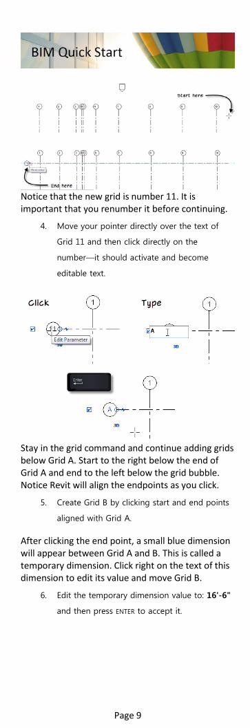
Notice that the new grid is number 11. It is important that you renumber it before continuing.
4. Move your pointer directly over the text of
Grid 11 and then click directly on the
number—it should activate and become
editable text.
Stay in the grid command and continue adding grids below Grid A. Start to the right below the end of Grid A and end to the left below the grid bubble. Notice Revit will align the endpoints as you click.
5. Create Grid B by clicking start and end points
aligned with Grid A.
After clicking the end point, a small blue dimension will appear between Grid A and B. This is called a temporary dimension. Click right on the text of this dimension to edit its value and move Grid B.
6. Edit the temporary dimension value to: 16'-6"
and then press ENTER to accept it.
Page 9

7. Repeat the exact process to create Grid C and
edit its distance from B to 16'-6" as well.
8. Add one more: Grid D and set its distance to
5'-6" this time.
If you need to adjust the length of grids after you create them, drag the endpoints. All aligned grids will stretch together.
9. Click and drag the open circle at the right end
of one of the horizontal grids. Drag it to
between Grid 6 and 7 and then release.
All of the grids move together. To prevent this, unlock the end.
10. Click the small lock icon at the right end of
Grid D to unlock it.
11. Drag this endpoint back to its original position
(to the right of Grid 10).
Notice that this time only Grid D is affected.
Page 10

12. Select Grid D. On the Modify tab, click the
Copy tool and then check the Multiple
checkbox on the Options Bar.
13. Start moving straight down, type in: 18'-6"
and then press ENTER.
14. Continue copying grids down at: 13'-9", 10'-
3", 7'-0", 13'-0" and 25'-3". (5) total; press
ENTER to finish copying.
The main portion of the building (Grids A through H) is “L” shaped. On the right side between Grids 8 – 10 a small projection to the south occurs. These are Grids I and J. So using the unlock procedure, we can shorten Grids I and J to just that area.
15. Unlock Grid I and drag its left end to the right
between Grid 7 and 8. Repeat for Grid J.
Notice that I and J lock back together automatically when they align.
16. Repeat the procedure to unlock the bottom
end of Grid 8, 9 and 10 and stretch them
below Grid J. (Be sure to unlock each time or
other grids will also stretch).
There are plenty of other adjustments that can be made. For example, you can hide and show the bubbles at either end with the small checkbox.
Page 11

17. Make any final adjustments to your grid layout
to match this figure:
It is a common office standard in many firms to omit letters “I” and “O” from grid designations to avoid having them confused with “1” and “0” on drawings. If you want to rename Grid I, first rename Grid J to K, and then you can change I to J. You cannot have two grids with the same name.
File completed to this point:
02_Medical Center_Grids_B.rvt
Exercise 3–Edit Levels
If you understand Grids, you have the basics you need to work with Levels as well. Levels run parallel to the ground. You cannot see them in a plan view, so to edit them, open an elevation or section. Otherwise, they will have similar behaviors to grids: the same types of control points, locking and stretching behavior, etc. You can continue in your previous file, or open the progress file (02_Medical Center_Grids_B.rvt) from the previous exercise. If you open the progress file, save it as with a new name.
1. On the Project Browser, beneath Elevations,
double-click South.
2. In an elevation view such as this, levels show
as dashed lines running horizontally and
Page 12

notice that the grids also show in this view. By
default, the file includes two levels: Level 1 and
Level 2.
For now we will adjust the height of the existing Level 2 and add two new levels for the roofs of the various portions of the building.
3. Select Level 2 onscreen.
4. Click directly on the dimension beneath the
Level 2 label. Edit the value to: 13'-4" and
then press ENTER.
You can add levels using techniques similar to adding grids. The level tool is on the Architecture tab, on the Datum panel. Its keyboard shortcut is LL. When you click points, they will attempt to align and lock to other levels just like grids. You can also copy levels as we did with grids. There is a difference in the final result with these two methods. When you add a new level, the default behavior also gives you new floor plan views associated to the new levels. When you copy, you do not get plans automatically and must add them later if desired. Let’s add levels with the level tool and introduce the “Pick” option.
5. On the Architecture tab, on the Datum panel,
click the Level tool (or type LL).
6. On the Modify | Place Level tab, on the Draw
panel, notice there are two icons. Click the
Pick Lines icon.
The Pick Lines option allows you to create levels from the edges of other geometry already in your model, in this case, we will offset from the existing levels.
Page 13

7. On the Options Bar, notice that the “Make
Plan View” box is checked. Click the Plan View
Types button next to this.
8. In the “Plan View Types” dialog that appears,
make sure that only “Floor Plan” is selected
and then click OK. (Click on an item to select
or deselect it in the list).
9. Also on the Options Bar, in the Offset field,
type: 13'-4" and then press ENTER.
10. Click once in an empty space in the view
window. (This makes the view active instead of
the text field).
11. Highlight Level 2 and wait for a dashed green
line to appear above its location. (Move the
mouse slightly if necessary to get it to appear).
12. Click to place the new level above.
13. Remain in the command, highlight the new
Level 3 that was just created and click again to
create a second level above it.
14. Click the Modify tool or ESC twice to finish the
command
15. Select Level 4. Click directly on the dimension
value on the level head (currently 40'-0") and
change the value to: 35'-6".
The level will move down. We can rename the levels the same way.
16. Click directly on the Level 4 label. It will
activate as editable text.
Page 14

17. Type in: Atrium Roof and then press ENTER.
As you are making this edit, glance over at your Project Browser. Since we used the “Make Plan View” checkbox above, we have a Level 3 and Level 4 floor plan on the Project Browser. When you enter the new name, Revit will ask you to confirm the renaming of the floor plans as well. If you want the names of the floor plans to also change, click Yes. If you want to leave the floor plan names unchanged, click No.
18. In the alert dialog, click Yes.
19. Repeat the process to rename Level 3 to:
Roof. Answer yes to change the plan name as
well.
You are welcome to experiment more with the other controls on the levels. The checkboxes at either end hide and show the levels as they did with the grids. You can also stretch one level and the aligned and locked ones will follow. You may also want to adjust the height of the grids to make them go above the levels.
20. Select any grid. Drag the open circle control at
the top to adjust the height.
21. Open either the East or West elevation view
and repeat for the lettered grids.
Page 15

Datum elements help you establish context in your project. Every model element you draw will be associated to a level or grid in your project. The best part is that later if you modify these datum elements, associated geometry will follow.
File completed to this point: 03_Medical Center_Levels.rvt
Walls There is not one “correct” way to start a new building project, but whichever process you follow, you will usually begin adding walls pretty early in the process. In this section, we will explore working with wall elements.
Exercise 4–Add exterior Walls
You can start adding walls anytime you have enough information to place them. In projects with a column grid, it is usually convenient to layout the grid first. This is what we did here. But you can start right in with adding walls instead if you wish. The process to adding walls is simple: layout walls in rough locations first and then come back and modify their locations, sizes and types. For this example, we will use the column grid to help us locate walls. If you don’t have a grid, simply click approximate points onscreen and then move the walls to their proper locations. You can continue in your previous file, or open the progress file (03_Medical Center_Levels.rvt) from the previous exercise. If you open the progress file, save it as with a new name.
Be sure that Level 1 floor plan is the current
view.
1. On the Architecture tab, on the Build panel,
click the Wall tool. The keyboard shortcut is
WA.
2. On the Properties palette, from the Type
Selector at the top, choose Generic - 12".
3. On the Options Bar, for the Offset type: 1'-0".
4. On the Modify | Place Wall tab, on the Draw
panel, click the Rectangle icon.
Page 16

5. For the starting point, snap at the intersection
of Grid lines 1 and A.
6. For the opposite corner, snap to the
intersection of Grid lines 6 and H.
Pay attention to the orientation of the walls before you click. If the rectangle is being formed inside of the two corners, tap the SPACEBAR to flip to the outside before you click the second point.
7. Stay in the command and create a second
rectangle from grid intersection D6 to H9.
8. Make one last rectangle from grid intersection
E9 to J10.
File completed to this point:
04_Medical Center_Ext_Walls_A.rvt Now that we have the basic exterior walls in place, we can use some standard tools to clean things up a bit. We have a few techniques we can use. The basic premise with all of them is the same: quickly sketch the rough form first (as we did in the previous steps) then modify the form.
Page 17

You can continue in your previous file, or open the progress file (04_Medical Center_Ext_Walls_A.rvt) from the previous exercise. If you open the progress file, save it as with a new name. Temporary Dimensions
9. Select the vertical wall to the left of Grid 6.
Two temporary dimensions will appear tying
its location to the walls at left and right.
10. Click directly on the dimension value at the
right (currently 2'-0") and change it to: 11'-8".
(You can type 11 SPACEBAR 8 and then ENTER).
The wall will move to the left. Next let’s clean up the overlapping portions. Using Trim/Extend tools
1. On the Modify tab, on the Modify panel, click
the Trim/Extend to Corner tool.
2. Click the horizontal wall at Grid G. Click on the
left side of the wall.
3. Click the lower portion of the wall at Grid 5
(this is the one we just moved). Be sure to
click the part below Grid G.
Page 18

You always need to click the portion of the wall that you wish to keep. So if you got the wrong thing, click the Undo tool on the Quick Access toolbar and try again.
4. Repeat the process at the walls at Grid 6 and
Grid D.
5. On the Modify tab, on the Modify panel, click
the Trim/Extend Single Element tool.
6. For the boundary edge, click the horizontal
wall at Grid H.
7. For the object to trim/extend, click the lower
portion of the vertical wall at Grid 9.
Page 19

8. Repeat above this by trimming the horizontal
wall at Grid E using the boundary wall at Grid
9.
9. Click the Modify tool or press ESC twice to
finish.
Making Selections Clicking on an element selects that element. Clicking a second element deselects the first and selects the new one instead. To select several items at once we have a few methods:
• You can use individual selection—hold down the CTRL key and click each wall one at a time.
• You can use chain selection—highlight (do not click) one wall, with it highlighted press (don’t hold down) TAB. The chain will highlight. Then click to select the chain. So it is: Highlight, TAB, then click.
• You can use window and crossing selections—click and drag a box around multiple objects. Click and drag from left to right to select elements within the box (window); click and drag right to left to select anything touching the box (crossing).
Practice each selection method. Click in empty space or press ESC to deselect everything and try again.
Page 20
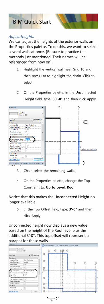
Adjust Heights We can adjust the heights of the exterior walls on the Properties palette. To do this, we want to select several walls at once. (Be sure to practice the methods just mentioned. Their names will be referenced from now on).
1. Highlight the vertical wall near Grid 10 and
then press TAB to highlight the chain. Click to
select.
2. On the Properties palette, in the Unconnected
Height field, type: 30'-0" and then click Apply.
3. Chain select the remaining walls.
4. On the Properties palette, change the Top
Constraint to: Up to Level: Roof.
Notice that this makes the Unconnected Height no longer available.
5. In the Top Offset field, type: 3'-0" and then
click Apply.
Unconnected height now displays a new value based on the height of the Roof level plus the additional 3'-0". This top offset will represent a parapet for these walls.
Page 21
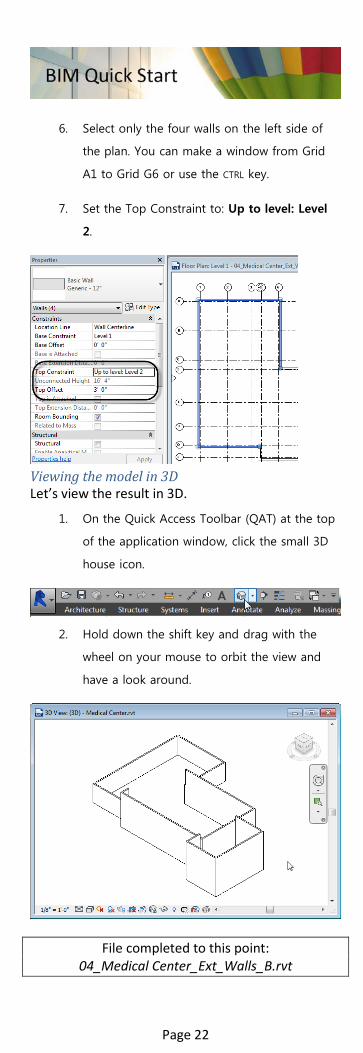
6. Select only the four walls on the left side of
the plan. You can make a window from Grid
A1 to Grid G6 or use the CTRL key.
7. Set the Top Constraint to: Up to level: Level
2.
Viewing the model in 3D Let’s view the result in 3D.
1. On the Quick Access Toolbar (QAT) at the top
of the application window, click the small 3D
house icon.
2. Hold down the shift key and drag with the
wheel on your mouse to orbit the view and
have a look around.
File completed to this point: 04_Medical Center_Ext_Walls_B.rvt
Page 22

Exercise 5–Add Interior Walls
Adding interior walls is quite similar to exterior walls. Let’s put in some interior spaces. You can continue in your previous file, or open the progress file (04_Medical Center_Ext_Walls_B.rvt) from the previous exercise. If you open the progress file, save it as with a new name. Draw Walls
Make sure the Level 1 floor plan is active.
Zoom in on the middle of the plan.
1. On the Architecture tab, on the Build panel,
click the Wall tool.
2. On the Properties palette, change the type to
Generic - 5". On the Draw panel, click the
rectangle icon.
3. Draw a rectangle in the middle of the plan.
The exact size is not important.
4. Cancel the command.
Edit using Temporary Dimensions 1. Select the horizontal wall at the bottom of the
rectangle you just drew.
Small round shape handles appear on the ends of the temporary dimensions indicating which points they measure to.
2. Click the small round shape handles on each
side of the dimension.
Page 23

Each time you click, it will move the witness lines of the dimension to a new location such as left, center and right faces of the walls.
3. When both witness lines are to the inside
faces of the walls, click in the dimension value
to set the size of the corridor to: 6'-0".
While this is effective, it can be a little tedious. An alternative is to create permanent dimensions and then use them to move the walls. Edit using Permanent Dimensions When elements that are dimensioned with permanent dimensions are selected, the values activate and become like temporaries. You can therefore use them to edit in the same way.
1. On the Annotate tab, on the Dimension panel,
click the Aligned tool.
2. On the Options Bar, from the first drop-down,
choose: Wall Faces.
3. Pick the inside face of the upper horizontal
exterior wall.
4. Pick each of the outside faces of the
horizontal walls making the rectangle in the
middle.
Page 24

5. Pick the inside face of the lower horizontal
exterior wall.
6. Click in empty white space to finish and place
the dimension.
7. Repeat in the other direction.
8. Cancel the command.
9. Select the top wall of the inside rectangle.
Notice that the permanent dimensions activate
like the other temporaries.
Page 25

10. Make the distance to the upper outside wall:
17'-9".
11. Select one of the vertical walls of the inside
rectangle and edit its value. Repeat on the
other to match the dimensions as shown.
Drawing Walls using Dimensions
1. Start the wall command again.
2. Draw a wall across the rectangle horizontally
from midpoint to midpoint.
3. On the left side of the rectangle, draw a
vertical wall 10'-6" from the left. Use the
temporary dimension to aid in placement.
Page 26

4. Repeat to create three more walls for a total
of five rooms across. The last room will be
smaller.
Using Location Line
1. Stay in the wall command. On the Options Bar,
change the Location Line to: Finish Face:
Interior.
2. Snap to the inside corner endpoint at the
exterior walls near grid intersection D6.
Page 27

3. Draw the wall straight down. The exact length
is not important.
4. Press ESC once to break the chain, but stay in
the wall command.
5. Snap to the inside endpoint near grid
intersection G5. Begin drawing to the right.
Notice that the wall is oriented the wrong way.
6. Tap the SPACEBAR on the keyboard to flip the
wall.
7. Draw it out horizontally. The length is not
important.
8. Use Trim/Extend to Corner to connect these
two walls.
Page 28
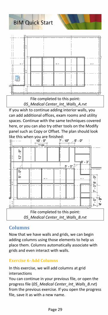
File completed to this point:
05_Medical Center_Int_Walls_A.rvt If you wish to continue adding interior walls, you can add additional offices, exam rooms and utility spaces. Continue with the same techniques covered here, or you can also try other tools on the Modify panel such as Copy or Offset. The plan should look like this when you are finished:
File completed to this point:
05_Medical Center_Int_Walls_B.rvt
Columns Now that we have walls and grids, we can begin adding columns using those elements to help us place them. Columns automatically associate with grids and even interact with walls.
Exercise 6–Add Columns
In this exercise, we will add columns at grid intersections You can continue in your previous file, or open the progress file (05_Medical Center_Int_Walls_B.rvt) from the previous exercise. If you open the progress file, save it as with a new name.
Page 29

Add Architectural Columns
1. On the Architecture tab, on the Build panel,
click the drop-down on the Column button
and choose: Column: Architectural.
2. On the Properties palette, from the Type
Selector, choose: 18"x18".
3. Down near the lower portion of the plan, click
to place a column at the intersection of grids
H and 6.
4. Repeat for H7, H8 and H9.
Notice how the architectural columns engage with the architectural walls.
5. Place some more along Grid line D and E.
Editing Columns If the column does not touch the wall, it will not merge. Some of the columns on Grid E do not merge for example. If you move either the wall or the Grid line they will merge when they touch.
1. Cancel the Column command.
2. Select Grid E.
3. Locate the temporary dimension over to the
right. Edit the value to: 5'-0".
4. Window select all of the columns (drag from
left to right surrounding all of them).
Page 30

5. On the ribbon, click the Filter button.
The “Filter” dialog appears allowing us to fine-tune the selection by removing categories we don’t need selected.
6. Uncheck everything except Columns and then
click OK.
7. On the Properties palette, set the Top Level to:
Roof.
8. On the QAT, click the Default 3D View icon to
view the results in 3D.
File completed to this point:
06_Medical Center_Columns.rvt
Inserts In Revit the term “Inserts” is applied to Doors, Windows and other elements that are associated (hosted) to walls and interact with the wall geometry. Specifically, windows and doors cut holes in the walls and remain attached to them as the design changes.
Exercise 7–Add Doors and Windows
In this exercise, we’ll add doors and windows to our model.
Page 31

You can continue in your previous file, or open the progress file (06_Medical Center_Columns.rvt) from the previous exercise. If you open the progress file, save it as with a new name. Placing Doors
Be sure that Level 1 floor plan is active.
1. On the Architecture tab, on the Build panel,
click the Door tool.
Move the mouse around the screen.
Notice that the door only appears when your cursor is highlighting a wall. Doors must be “hosted” by walls. They cannot be placed free-standing in space.
2. Place the mouse on the horizontal exterior
wall at the corridor leading out between Grids
8 and 9.
If you move the mouse slightly inside and outside the building the door direction changes. If you tap the SPACEBAR, you can flip it side to side as well.
3. When the door is pointing outside the
building, click to place it.
The door will appear and will cut a hole in the receiving wall. The door is hosted to that wall. If that wall is moved the door will move. If the wall is deleted, the door will also be deleted. Notice where the temporary dimensions appear for this door. They measure to the door’s center. You may prefer to measure to the opening instead.
4. On the Manage tab, click the Additional
Settings drop-down and choose: Temporary
Dimensions.
5. For Walls, choose: Faces and for Doors and
Windows choose: Openings and then click OK.
Page 32

When you dismiss this dialog, the Door command should still be active. If you canceled it, please run it again. Notice that as you move the mouse around now, the doors measure to the openings instead of the centers.
6. Using the temporary dimensions as a guide,
place a few more doors at some of the interior
rooms set 6" from the corner of the room.
Remember the SPACEBAR to flip.
Door Families The door we are using is a single-flush door. This is the “family.” In some cases you want a double door or doors with vision panels. These are different families that must be loaded into the project.
1. Remain in the Door command and on the
Modify | Place Door tab, click the Load Family
button.
2. In the “Load Family” dialog, double-click the
Doors folder.
3. Hold down the CTRL key and select: Double-
Flush.rfa, Single-Flush Vision.rfa and Single-
Glass 1.rfa.
Page 33

4. Click Open to load all three families.
On the Properties palette, the Type Selector at the top now displays four families and their types (the original one plus the three we just loaded). The types are the predefined sizes for each family.
5. Choose one of the newly loaded types and
add it to the plan. Continue to place several
doors.
File completed to this point:
07_Medical Center_Doors-and-Windows_A.rvt Adding Windows Adding Windows is the same as adding doors.
Page 34

You can continue in your previous file, or open the progress file (07_Medical Center_Doors-and-Windows_A.rvt) from the previous exercise. If you open the progress file, save it as with a new name.
1. On the Architecture tab, on the Build panel,
click the Window tool.
There is only a single family (Fixed) loaded in this file. You are welcome to click Load Family and load other styles of window if you prefer, or you can simply use the Fixed one.
2. Place some windows in the rooms at the top
of the plan.
By default the temporary dimensions for the windows reference the walls and typically those nearest the windows. If you want to space your windows relative to other geometry like the exterior features of the building or the column grid, you can use the technique covered above for walls and first add some permanent dimensions and then modify them.
3. On the QAT, click the Aligned Dimension tool.
4. Place the first witness line at the outside face
of the vertical wall at Grid 6.
5. Place a witness line at the center of each
window.
6. Click in empty space to finish.
7. Select the leftmost window.
Page 35

8. Edit the dimension on the left to move the
window and set its distance to 4'-0" from the
wall.
9. Working left to right, select a window, then
edit the dimension on the left. Then move to
the next one. A distance of 10'-0" works well.
Even though the locations of the windows inside the rooms are now somewhat random, the spacing from the exterior of the building is even.
File completed to this point: 07_Medical Center_Doors-and-Windows_B.rvt
Curtain Walls Curtain walls are walls with a complex structure. We can define a spacing of grid lines in both the horizontal and vertical dimensions and even apply mullions to these grids. Use curtain walls to define glazing walls, stone or metal panelization or any number of other complex design ideas.
Exercise 8–Add Curtain Walls
Curtain walls can be used for a variety of design features. Whether your application is a full glazed wall exterior curtain wall, strip window or interior glass partitions, the curtain wall can prove quite versatile. You can continue in your previous file, or open the progress file (07_Medical Center_Doors-and-Windows_B.rvt) from the previous exercise. If you open the progress file, save it as with a new name. Create a glass entryway
Be sure that the Level 1 floor plan is open.
1. Zoom in around the lower-right portion of the
plan (between Grids J9 and K10).
2. On the Architecture tab, on the Build panel,
click the Wall tool.
Page 36

3. On the Properties palette, from the Type
Selector, choose the: Curtain Wall: Storefront
type.
4. For the Unconnected Height, input: 14'-0".
5. Click the first point directly on the horizontal
wall running along Grid J about 3'-0" from
Grid 10.
6. Move the mouse straight down and click when
the dimension reads: 10'-0".
7. Move horizontally to the left and click when
the dimension reads: 22'-0".
8. Move straight back up and click on the
horizontal wall to finish.
Adjust a Curtain Wall You can adjust the mullion spacing as needed. This is sometimes easier in elevation.
1. On the Project Browser, double-click the South
elevation view to open it.
2. Zoom in on the Curtain Wall at the right.
3. On the Architecture tab, click the Curtain Grid
tool.
4. Highlight the bottom edge of the curtain wall.
A dashed vertical line will appear indicating
where the gird will go when you click.
Page 37

5. Click within the second bay from the left
about 1'-0" from the middle bay.
6. Create another one in the fourth bay (to the
right of the middle one).
7. Press ESC twice to cancel.
Adding a Door to a Curtain Wall You can’t use the normal door tool to add a door in a curtain wall. Instead you replace one of the panels with a curtain wall door.
1. Hold down the CTRL key and click to select
each of the mullions in the middle bay as
shown.
Page 38

2. On the Modify tab, on the Modify panel, click
the Unpin tool or press UP.
3. Press the DELETE key to remove these mullions.
4. Click one of the grid lines that remain. On the
Modify ribbon, click the Add/Remove
Segments button.
5. Click again on the empty spot.
The grid segment will remove merging the two bays.
6. Repeat on the other grid line.
7. On the Insert tab, click the Load Family button.
8. Browse to the Doors folder, select the Curtain
Wall Dbl Glass.rfa family and then click Open.
Page 39

9. Highlight the bottom edge of the modified
center bay. Press TAB to highlight the panel
within that bay and then click.
You may have to TAB a second time to
highlight the panel.
10. Unpin this panel.
11. On the Properties palette, from the Type
Selector, choose: Curtain Wall Dbl Glass.
12. Return to Floor Plan Level 1.
File completed to this point: 08_Medical Center_Curtain-Wall_A.rvt
Replacing a Wall with a Curtain Wall You can replace walls already in the file with Curtain Walls as the building design progresses.
1. Select the exterior horizontal wall along Grid E.
2. With the CTRL key held down, also select the
horizontal wall at Grid J and the small vertical
wall at Grid 9 between J and H.
Page 40

3. With these three walls selected, on the
Properties palette, change them to Curtain
Wall: Storefront.
Zoom in and study the results. If necessary, you can tap the SPACEBAR to flip the walls while they are still selected to make sure the glazing is on the outside.
For now we will ignore the intersection of the curtain wall and the wall at J10. But let’s address the connection between the curtain wall and the entry foyer built in the previous exercise.
4. On the Modify tab, on the Modify panel, click
the Align tool.
5. For the alignment reference, click on the grid
line of the second mullion from the left along
the curtain wall at Grid J.
6. For the entity to align, click the left curtain
wall of the foyer.
The curtain wall moves just fine, but notice that the spacing of mullions along the bottom curtain wall adjusts as well; but they don’t stay symmetrical. If this is not obvious, try aligning the curtain wall on
Page 41

the other side as well. It will be more obvious then.
7. Cancel the command and then on the QAT,
click the undo tool to reverse the alignments
(you can also press CTRL+Z).
8. Select the lower horizontal curtain wall (the
one with the door).
9. On the Properties palette, click the Edit Type
button.
10. In the “Type Properties” dialog, click the
Duplicate button, input a new name such as:
Front Entry and then click OK.
11. Remaining in “Type Properties,” beneath
Vertical Grid and Horizontal Grid, choose
None for the Layout of both.
12. Click OK to finish.
13. A warning will appear. Click OK (do NOT click
Delete Gridline or Cancel).
Page 42

What we have done here is disable the automatic spacing of gridlines on this segment of curtain wall. This means that now when you move the adjoining walls, they will no longer try to adjust the mullion spacing.
14. Repeat the Align process from above to align
both sides of the foyer to the mullions of the
curtain wall on Grid line J.
15. Use Trim/Extend to extend the curtain walls
and enclose the space.
File completed to this point:
08_Medical Center_Curtain-Wall_B.rvt Embed a Curtain Wall We can also use curtain walls like windows. We do this by embedding them in another wall. In this way we can create a strip window along the south elevation of the building.
1. On the Project Browser, locate and expand the
Families branch.
2. Next expand Curtain Wall Mullions and then
Rectangular Mullion.
3. Right-click on 2.5" x 5" rectangular and
choose: Duplicate.
2.5" x 5" rectangular 2 will appear.
4. Right-click and choose Rename. Name it: 6" x
24" rectangular.
Page 43

5. Double-click the new mullion to edit its
properties.
6. Change the Thickness to: 2'-0", and both the
Width on side 1 and side 2 to: 3" each. Click
OK to finish.
7. Stay on the Families branch, expand Walls,
then Curtain Wall.
8. Right-click and Duplicate Curtain Wall and
then Rename it to: Ribbon Window.
9. Edit the Properties of Ribbon Window and
change the all of the Border Type mullions to
the new 6" x 24" rectangular.
There are four total: Border 1 and 2 for each
of horizontal and vertical.
Page 44

10. At the top, for the Join Condition, choose:
Border and Vertical Grid Continuous and
then click OK to finish.
11. On the Architecture tab, on the Build panel,
click the Wall tool.
12. On the Properties palette, from the Type
Selector, choose the: Curtain Wall: Ribbon
Window type.
13. For both the Base Offset input: 3'-4".and for
the Unconnected Height, input: 5'-0".
14. Draw the new curtain wall directly on top of
the centerline of the existing horizontal wall at
Grid H. Make it about 50'-0" long.
15. Cancel the command to finish.
The curtain wall will be centered on its host wall.
16. Select the curtain wall. Edit the 6" temporary
dimension and change it to zero.
Page 45
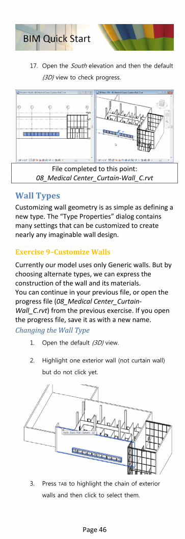
17. Open the South elevation and then the default
{3D} view to check progress.
File completed to this point:
08_Medical Center_Curtain-Wall_C.rvt
Wall Types Customizing wall geometry is as simple as defining a new type. The “Type Properties” dialog contains many settings that can be customized to create nearly any imaginable wall design.
Exercise 9–Customize Walls
Currently our model uses only Generic walls. But by choosing alternate types, we can express the construction of the wall and its materials. You can continue in your previous file, or open the progress file (08_Medical Center_Curtain-Wall_C.rvt) from the previous exercise. If you open the progress file, save it as with a new name. Changing the Wall Type
1. Open the default {3D} view.
2. Highlight one exterior wall (not curtain wall)
but do not click yet.
3. Press TAB to highlight the chain of exterior
walls and then click to select them.
Page 46

4. On the Properties palette, from the Type
Selector, choose: Exterior – Brick on Mtl.
Stud.
When you do this an error will appear. This is because the curtain walls are joined to the walls we are changing and this change forces the automatically generated mullions and grids to adjust. Revit indicates that some elements must be deleted. This is OK in this case, as new ones will be created automatically to replace the ones being deleted. Since we are in 3D, you can see the elements in question highlighted in orange.
5. In the error dialog, click the Delete Element(s)
button.
6. Zoom in and explore the change.
Notice that as you zoom in closer, a brick pattern appears on the walls. If your brick appears on the inside of the building instead, chain select the walls again and then tap the SPACEBAR to flip them.
7. When finished, open the Level 1 floor plan
view.
In plan view, the change to the exterior walls will not be obvious. This is because the plan view is set to display course level of detail. In course level, only the outlines of the walls display.
8. On the View Control Bar at the bottom left
corner of the view, click the Level of Detail
pop-up and choose Medium.
Page 47

If you look carefully at the dimensions in the plan, you will notice that some have changed. This is because in addition to now displaying internal components, changing from Generic to Brick on Metal Stud has also changed the thickness of the walls. Editing a Wall Type Let’s assume that the design called for keeping the thickness of the wall unchanged when changing types. In other words, let’s say we needed the wall to remain 1'-0" thick. Create a new type and modify it to accomplish this.
1. Select any exterior wall and then on the
Properties palette, click the Edit Type button.
If you want to change all existing walls of this type throughout the entire project, simply make your edits and then click OK. If instead you would prefer to preserve the original, use the Duplicate button to make a copy and assign it instead. Best practice is to duplicate.
2. In the “type Properties” dialog, click the
Duplicate button and then name the new type:
Exterior - Brick on 4" Mtl. Stud.
3. Next to the Structure item, click the large Edit
button.
4. In the Thickness column, next to layer 6,
change the value from 6" to: 4".
5. For Layer 9, change the thickness to: 0' 0 5/8".
6. Click OK twice to complete the change.
Page 48

7. If you get the curtain wall error again, click
Delete Elements again.
8. Select a different brick wall, right-click and
choose: Select all Instances > Visible in View.
9. From the Type Selector, choose your new wall
type for these walls. If the error appears, click
Delete Elements.
All dimensions should return to their previous values. You will not always be able to adjust the wall thickness like this in every project. In cases where the walls must change thickness, you may need to adjust some of their locations after the change. Adding Walls with the new Type Once you have created a new wall type, it can be used like any other.
1. On the Project Browser, double-click to open
the Level 2 floor plan.
2. On the Architecture tab, on the Build panel,
click the Wall tool.
Pay close attention to the settings on the Properties palette as Revit is remembering the curtain wall we drew previously and defaulting to those values.
3. Change the type to: Exterior – Brick on 4"
Mtl. Stud.
4. Set the Location Line to: Finish Face: Exterior.
5. Verify that Base Constraint is: Level 2 and set
the Base Offset to: 0.
6. For Top Constraint, choose: Up to level: Roof
and set the Top Offset to: 3'-0".
Page 49

Zoom in near the intersection of Grid G and 4.
7. Snap to the outside endpoint of the short wall
there.
8. Draw straight up and click when you are
aligned with the horizontal wall at Grid D.
9. Draw a small horizontal wall snapping back to
the existing wall near Grid intersection D6.
10. Click Modify or press ESC twice to finish.
11. Reopen the {3D} view, hold down the SHIFT key
and drag with the wheel to orbit around and
see the results.
File completed to this point:
09_Medical Center_Wall-Types.rvt
Page 50

Floors and Roofs Floors and Roofs share many common characteristics. Both are “sketch-based” elements where you draw a two-dimensional outline representing the floor or roof shape. Floors and roofs can be flat or sloped.
Exercise 10–Add Floors
In this lesson we’ll add floors to our building. To build a floor element, you simply enter a special mode that Revit calls “sketch mode” and sketch the outline of the floor shape. You can continue in your previous file, or open the progress file (09_Medical Center_Wall-Types.rvt) from the previous exercise. If you open the progress file, save it as with a new name. Create a Floor Element
1. On the Project Browser, double-click to open
the Level 1 floor plan.
The simplest way to create a floor is to use the existing walls to sketch the edges.
2. On the Architecture tab, click the Floor button.
The drawing window grays out to indicate that you are in sketch mode. On the Modify tab, the Boundary Line and Pick Walls buttons are highlighted and active. On the Options Bar, the “Extend into wall” checkbox is checked. All of these defaults will work well for most floors you create. Leave them all set this way for this example.
3. In the drawing window, click on one of the
exterior walls.
A magenta line will appear near the middle of
the wall. If it appears near the edge, click the
small flip control at the midpoint of the line.
4. Continue clicking on each of the exterior walls
to create a boundary all the way around the
shape of the building.
Some manual cleanup will be required in the areas indicated.
Page 51

5. For the lines at Grid 9 and Grid E, use
Trim/Extend to a Corner.
6. Remember to click the side of the line you
want to keep, so along Grid 9, click the upper
portion of the line.
7. Remaining in Trim/Extend to Corner, clean up
the corner at Grid intersection E10 and the
one at J9.
We will use Trim/Extend to Corner at the foyer area as well, but before doing so, we need to split the sketch line at Grid J.
8. On the Modify tab, on the Modify panel, click
the Split Element tool (or press SL).
9. Click near the middle of the line on Grid J to
split it in two.
10. Use Trim/Extend to Corner to finish up.
Page 52

11. On the Modify tab, on the Mode panel, click
the Finish Edit Mode button (green
checkmark).
Create a Section View To help us visualize the floor slab on the second floor, let’s make a section view through the building first.
1. On the View tab, on the Create panel, click the
Section tool.
2. Click outside the building in the space
between Grids 7 and 8.
3. Move straight down and then click a second
point outside the building at the bottom.
Page 53

A new Sections branch will appear on Project Browser.
4. On Project Browser, double-click to open
Section 1.
5. From the View Control Bar, for the Level of
Detail, choose Medium.
6. On the Project Browser, double-click to open
the Level 2 floor plan.
7. On the View tab, on the Windows panel, click
the Tile button.
If you have more than Level 2 floor plan and Section 1 open, you can close the other views and tile again.
8. Type ZA to zoom both windows to fit.
Add a Second Floor Now let’s create a floor for Level 2
1. Click in the Level 2 floor plan view to make it
active.
Page 54

This floor will be confined to the middle portion of the building with a small extension to the right in the atrium space.
2. On the Architecture tab, click the Floor button.
3. Again, accept all defaults.
4. Select the exterior walls of the rectangular
portion of the building in the center. (There
are 6 total).
5. Split the vertical line on the right.
6. On the Modify tab, on the Draw panel, click
the Line tool.
7. Draw three lines as shown. Use the dimensions
indicated to help you place them.
8. Trim/Extend the corners to clean up.
Page 55

9. On the Modify tab, on the Mode panel, click
the Finish Edit Mode button (green check).
A message will appear asking if we want to attach the tops of the walls to the bottom of the floor. You can see this highlighted in both plan and section. For most of our walls this is a good idea. But for the two on the left portion of the building, we would not want this as they are exterior walls. Unfortunately with this command you cannot adjust the selection. You can only answer yes or no. In this case, let’s answer yes and then come back and remove the two we don’t need attached.
10. In the dialog click Yes.
A second message will highlight just the exterior walls. This one is asking if we want to clean up the connection between the floor and exterior walls. Let’s also answer yes here.
When finished, take a close look at the connections in the section view.
Detach Walls from a Floor Now let’s detach the two exterior walls.
1. On the QAT click the Default 3D View icon.
2. Hold the SHIFT key and drag the wheel to orbit
around the north side of the building.
Page 56

Note the two exterior walls that are now too low.
3. Hold the CTRL key and click to select these two
walls.
4. On the Modify tab, on the Modify Wall panel,
click the Detach Top/Base button.
5. Click on the edge of the floor element. (You
can click anywhere, zoom and orbit if
necessary).
File completed to this point:
10_Medical Center_Floors.rvt
Exercise 11–Add Roofs
There are a couple ways to make roofs in Revit. Footprint roofs are very similar to floors. Extrusion roofs are sketched a little differently offering some alternative roof shapes. You can continue in your previous file, or open the progress file (10_Medical Center_Floors.rvt) from the previous exercise. If you open the progress file, save it as with a new name. Add a Footprint Roof We’ll need two footprint roofs, one for each of the brick portions of the building.
1. On the Project Browser, double-click to open
the Level 2 floor plan.
2. Zoom in on the left side of the building.
This portion of the building is one story tall, so we will build its roof on the second floor level.
3. On the Architecture tab, on the Build panel,
click the Roof by Footprint tool.
Most options are identical to floors. We have the Boundary Line and Pick Walls tools active. We sketch the shape of the roof’s footprint in plan. Just like floors. However, by default, Roofs default to sloped roofs. This is controlled by the “Defines
Page 57

Slope” checkbox on the Options Bar. For this building, we need flat roofs.
4. On the Options Bar, uncheck Defines Slope.
5. Like the floors previously move around the
plan and click once on each wall that you
want to use for the sketch.
This time the sketch lines go to the inside face
of the walls.
6. Finish the roof.
7. On the Project Browser, double-click to open
the Roof plan.
8. Repeat the process to create a flat roof for the
middle portion of the building.
As before, there are six lines here.
Page 58

Creating an Reference Plane For the atrium portion of the building, we will create a custom shaped roof using the extrusion roof tool. We need to start with a reference plane. Reference planes are essentially guidelines that will help us locate the sketch and set the depth of the roof.
Remain in the Roof plan view.
1. On the Architecture tab, on the Work Plane
panel, click the Ref Plane button.
2. Click a point to the left of the atrium (between
Grid 8 and 9) and about halfway between
Grids J and K.
3. Move the mouse horizontally to the right and
click the other end past the outside of the
building.
4. Change the value of the temporary dimension
between Grid K and the reference plane to:
10'-0".
5. Cancel the command, select the new
Reference Plane and then on the Properties
palette, in the Name field type: Atrium Roof.
Page 59

Reference planes are similar to grids and levels except they have no restrictions on orientation (they can be drawn in any direction) and then don’t have annotation. Use them as work planes for geometry. Creating an Extrusion Roof To draw the extrusion roof sketch, we must work in a view parallel to the work plane (our new reference plane in this case).
1. Open the South elevation.
2. On the Architecture tab, on the Build panel,
click the Roof drop-down button and choose:
Roof by Extrusion.
3. In the “Work Plane” dialog, from the Name list,
choose: Reference Plane: Atrium Roof and
then click OK.
4. In the “Roof Reference Level and Offset”
dialog, accept Atrium Roof and zero and click
OK.
Zoom in near the bottom-right side of the
elevation at the exterior wall on the right.
Page 60

5. Click the first point of the sketch at the
endpoint on the outside of the right-most
exterior wall (TAB if necessary).
Roll the wheel of your mouse down to zoom
back out before clicking the second point.
6. Move the mouse up well beyond the top of
the building and slightly to the left of Grid 10.
7. When the angle reads 94°, click to place the
second point. Press ESC once to break the
chain but remain in the sketch.
On the Draw panel, make sure that the line
tool is still active.
8. Click the first point about 5'-0" to the left of
Grid 9.
9. Move down and to the right past the right
side of the building and click when the angle
reads 6°.
Page 61

10. Use Trim/Extend to Corner to join the two
diagonal lines to one another.
11. On the Mode panel, click the Finish Edit Mode
(green checkmark) button.
12. With the new roof still selected, on the
Properties palette, for Rafter Cut, choose: Two
Cut – Square.
13. Edit the Extrusion End to: 70'-0".
Attach walls to Roof Let’s cleanup the connections between the walls and the roof.
1. Delete the Generic - 12" wall on the outside of
the atrium.
2. Select the three curtain walls in the atrium. (It
is easiest to do this in the Level 1 plan view
using the CTRL key).
Page 62

3. On the Modify | Walls tab, on the Modify Wall
panel, click the Attach Top/Base button.
4. Click the extrusion wall we just created.
An error will appear indicating that mullions cannot be created. This is expected as we are cutting the shape of the curtain walls to match the slope of the roof. It is save to click the Delete Elements button here.
5. In the error dialog, click the Delete Element(s)
button.
When you do this, the curtain walls will be unacceptable. Large portions disappear. There is an easy fix to this.
6. Undo the previous command.
7. In the Level 1 floor plan, select the extrusion
roof and move it to the right slightly about 2"
is plenty.
8. Repeat the attach top/base command.
This time it will work much better.
File completed to this point:
11_Medical Center_Roofs.rvt.rvt
Vertical Circulation Create stair elements from types defining the slope and code requirements of the stairs. Railings can be created directly with the stair or separately as freestanding guardrails.
Page 63

Exercise 12–Add Stairs and Railings
In this exercise, we will add a simple egress stair to our model. You can continue in your previous file, or open the progress file (11_Medical Center_Roofs.rvt) from the previous exercise. If you open the progress file, save it as with a new name. Create the Stair well space First we need a location for the stairs.
1. On the Project Browser, double-click to open
the Level 2 floor plan.
2. Select the two walls added above in “Adding
Walls with the new Type” topic (near Grids 4
and D).
3. On the Modify tab, on the Clipboard panel,
click the Copy to Clipboard button (or press
CTRL + C).
4. On the clipboard panel, from the Paste drop-
down, choose: Aligned to Selected Levels.
5. Select Level 1 in the list and then click OK.
6. On the Project Browser, double-click to open
the Level 1 floor plan to see the results.
A warning will appear in the lower right corner indicating that walls overlap. It is safe to ignore this. We will fix the problem now. The walls we pasted have a 3'-0" top offset. We need to set this to zero. Take note of the context buttons on the Modify ribbon. There is one labeled: “Show Related Warnings.” If you missed the warning and dismissed it too quickly, this would allow you to see it again.
Page 64

7. With both walls still selected, on the Properties
palette, change the Top Offset to: 0.
Notice that the “Show Related Warnings” button is no longer displayed. This is because we have resolved the previous warning.
8. Keep these two walls selected and on the
Properties palette, change the Location Line
to: Finish Face: Interior.
9. From the Type Selector choose: Basic Wall:
Interior – 6 1/8" Partition (2-hr).
10. Select the vertical wall near Grid 6 and the
small horizontal one near Grid G and change
them to this type as well.
Within this long thin space, we will add our egress stair. Add a Stair Now let’s add the stairs.
1. Zoom in on the area between Grids 5 and 6
just below the corridor door.
2. On the Architecture tab, on the Circulation
panel, click the Stair drop-down and choose:
Stair by Component.
3. On the Options Bar, for Location Line, choose:
Exterior Support: Right.
Page 65

4. Also on the Options Bar, for the Actual Run
Width, input: 3'-8".
5. On the Modify | Create Stair ribbon, on the far
right, click the Railing button.
6. Choose: Handrail – Pipe, click the Stringer
radio button and then click OK.
We’ll accept the remaining defaults for the stair and begin drawing it.
7. Click the first point on the face of the wall at
Grid 6 near the bottom.
8. Move the mouse straight up along the face of
the wall and when the light gray message
indicates that 12 Risers have been created,
click the second point.
9. Click the third point across the space inline
with the second tread and the face of the wall
at Grid 5.
10. Move straight down and click the final point
when all risers are created.
Page 66
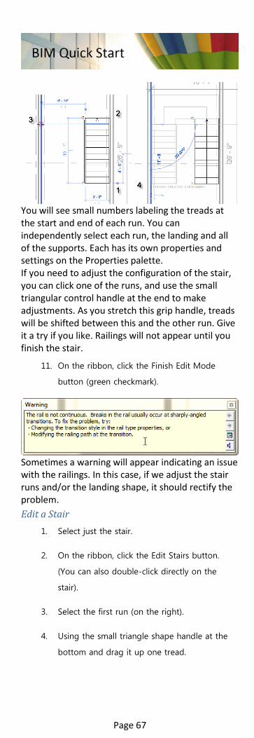
You will see small numbers labeling the treads at the start and end of each run. You can independently select each run, the landing and all of the supports. Each has its own properties and settings on the Properties palette. If you need to adjust the configuration of the stair, you can click one of the runs, and use the small triangular control handle at the end to make adjustments. As you stretch this grip handle, treads will be shifted between this and the other run. Give it a try if you like. Railings will not appear until you finish the stair.
11. On the ribbon, click the Finish Edit Mode
button (green checkmark).
Sometimes a warning will appear indicating an issue with the railings. In this case, if we adjust the stair runs and/or the landing shape, it should rectify the problem. Edit a Stair
1. Select just the stair.
2. On the ribbon, click the Edit Stairs button.
(You can also double-click directly on the
stair).
3. Select the first run (on the right).
4. Using the small triangle shape handle at the
bottom and drag it up one tread.
Page 67

5. On the Modify tab, click the Align tool.
6. For the point of alignment, click the bottom
edge of the last tread (where it says 23).
7. Next click the edge at tread 1. Cancel the
command when finished.
Notice that the first run will move into alignment with the second one.
8. Select the landing.
Notice all of the shape handles on each edge. We can use these to adjust the shape of the landing. There is also a temporary dimension for the overall width. Let’s adjust that slightly.
9. Click in the value of the temporary dimension
and make the overall landing width: 4'-0".
10. Finish the stairs.
To complete the stair, you can add a few more walls and fine-tune its location by simply moving the stair.
Page 68

File completed to this point: 12_Medical Center_Stair.rvt
Components Component families of all kinds are included with the software. You can also locate others online or even create them yourself.
Exercise 13–Add Fixtures, Furnishings and Equipment
We can add all sorts of components to our models: toilets, sinks, desks, chairs, office equipment, etc. You can continue in your previous file, or open the progress file (12_Medical Center_Stair.rvt) from the previous exercise. If you open the progress file, save it as with a new name. Add Plumbing Fixtures
1. In the Level 1 floor plan, zoom in on the three
small rooms to the left of the atrium space.
2. On the Architecture tab, click the Component
tool.
3. On the Modify tab, click the Load Family
button.
4. Browse to the
Plumbing\Architectural\Fixtures\Water
Closets folder.
5. Select the Toilet-Commercial-Wall-3D.rfa
family and then click Open.
Page 69

6. Click on the face of a wall to place the
component. Place one in each toilet room.
7. Click Load Family again. This time browse to
the Plumbing\Architectural\Fixtures\Sinks
folder.
8. Hold down the CTRL key and select the Sink-
Mop-2D.rfa family and the Sink-Single-2D.rfa
family. Click Open.
9. Place a sink in each toilet room.
10. From the Properties palette, switch to the mop
sink and place it in the janitor’s closet between
them. Use the spacebar to rotate it before
placement.
Place Casework and Furniture Let’s add a few items to some of the exam rooms
1. Remain in the Component tool.
2. On the ribbon click Load Family.
3. Browse to the Casework\Counter Tops folder.
Page 70
4. Select the Counter Top.rfa family and then
click Open.
5. Tap the SPACEBAR to rotate it.
Zoom in on the exam room at Grid
intersection D6.
6. Snap to the lower left corner of the room to
place the counter.
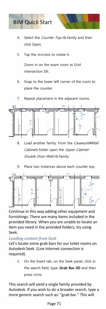
7. Repeat placement in the adjacent rooms.
8. Load another family. From the Casework\Wall
Cabinets folder open the Upper Cabinet-
Double Door-Wall.rfa family.
9. Place two instances above each counter top.
Continue in this way adding other equipment and furnishings. There are many items included in the provided library. When you are unable to locate an item you need in the provided folders, try using Seek. Loading content from Seek Let’s locate some grab bars for our toilet rooms on Autodesk Seek. (Live Internet connection is required).
1. On the Insert tab, on the Seek panel, click in
the search field, type: Grab Bar-3D and then
press ENTER.
This search will yield a single family provided by Autodesk. If you wish to do a broader search, type a more generic search such as: “grab bar.” This will
Page 71

yield a variety of manufacturer provided options instead.
2. Click on the link for the item that appears.
On the right side usually more than one
version is provided.
3. Check the one you wish to download and then
click the Download Selected to Local button.
4. Follow the remaining prompts to login, accept
terms and download the file.
5. Once downloaded, you can return to Revit, run
the Component tool again, Load Family and
browse to where you downloaded the Seek
component.
6. Place an instance in each toilet room.
7. Rotate and flip as necessary.
Page 72

File completed to this point:
13_Medical Center_Components.rvt
Working with Others While working in Revit it is common for you to have to access information from other programs such as AutoCAD. Revit both reads and writes DWG files and other common formats as well.
Exercise 14–Link a CAD file
When you receive design data in a DWG file, you can import it directly into Revit and use the information to help you coordinate your design work. You can continue in your previous file, or open the progress file (13_Medical Center_Components.rvt) from the previous exercise. If you open the progress file, save it as with a new name. Create a link to a CAD file Let’s import a CAD file of the site plan information. It will be linked so that we can update it easily later if the CAD file changes.
1. On the Project Browser, double-click to open
the Site plan view.
2. On the Insert tab, click the Link CAD button.
CAD files are typically organized on layers and each layer is often assigned a color. The Colors and Layers/Levels settings allow you to customize which layers are imported and if their colors are maintained. Usually Revit can read the correct units and “Auto-Detect” works fine. Since it is unlikely that the CAD file uses the same origin as Revit, using the Center to Center option is a good starting point and then we can move the file. If you want the file to appear in all views and be able to create
Page 73

topography from it, be sure that “Current view only” is not checked.
3. Select the file named: Site_Plan.dwg, accept
the default settings (make sure Current View
Only is not checked) and then click Open.
4. Click anywhere on the imported file to select
it.
5. On the ribbon, click the Query button.
6. Click again on some of the linework in the
CAD file.
A dialog will appear indicating information about the selected element’s layer.
7. When finished, click OK and then on the
ribbon, click the Modify tool.
Orient the CAD file Adjusting the orientation of the CAD link to match the project is as simple as move and rotate.
1. Select the CAD file and on the ribbon, click the
Move tool.
2. Snap to the endpoint in the CAD file that
corresponds to the outside corner of the
building.
3. For the second point of the move, snap to the
corresponding point on the building geometry.
Page 74

Perform similar steps to rotate.
4. On the Modify panel, click Rotate.
5. Tap the SPACEBAR to change the center of
rotation.
6. Snap the rotation center point at the same
point you used to move the file.
7. Click at the opposite end of the angled line in
the CAD file.
8. Rotate down and snap to the building
geometry.
Page 75

9. Open the South elevation view.
Notice that the lines in the CAD file are above the building. Back in the Site plan, if you zoom in you can see some text labels indicating the heights of these contour lines. The file needs to move down 53' to properly align with the building.
10. Use the move command again. Click any base
point.
11. Move straight down, type 53 and then press
ENTER.
12. Open the default {3D} view and orbit around
(hold the SHIFT key while dragging with the
wheel button).
The contours are at the correct heights, but the other information in this file is at 0. This is common in site files. Create a Toposurface We can use the contours to create a toposurface upon which our building can sit.
1. On the Massing & Site tab, click the
Toposurface button.
2. On the Modify | Edit Surface tab, click the
Create from Import drop-down button and
choose: Select Import Instance.
Page 76
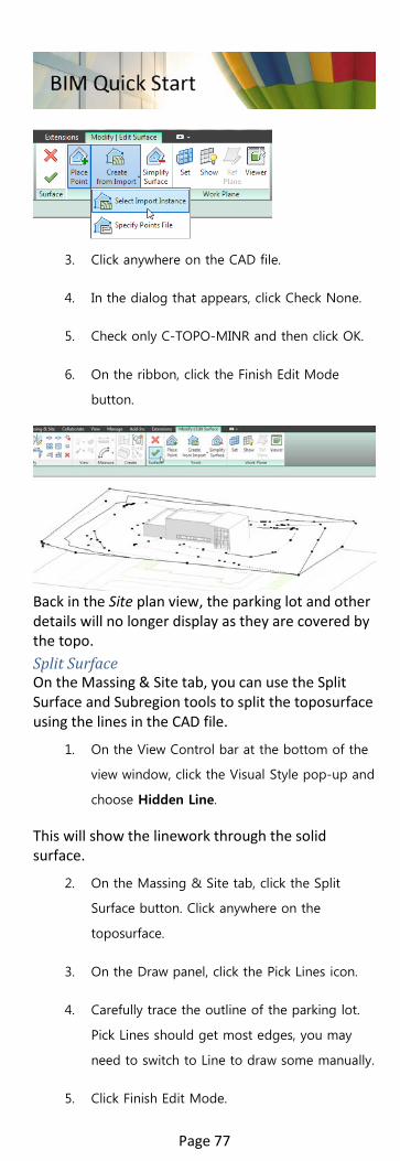
3. Click anywhere on the CAD file.
4. In the dialog that appears, click Check None.
5. Check only C-TOPO-MINR and then click OK.
6. On the ribbon, click the Finish Edit Mode
button.
Back in the Site plan view, the parking lot and other details will no longer display as they are covered by the topo. Split Surface On the Massing & Site tab, you can use the Split Surface and Subregion tools to split the toposurface using the lines in the CAD file.
1. On the View Control bar at the bottom of the
view window, click the Visual Style pop-up and
choose Hidden Line.
This will show the linework through the solid surface.
2. On the Massing & Site tab, click the Split
Surface button. Click anywhere on the
toposurface.
3. On the Draw panel, click the Pick Lines icon.
4. Carefully trace the outline of the parking lot.
Pick Lines should get most edges, you may
need to switch to Line to draw some manually.
5. Click Finish Edit Mode.
Page 77

If you get an error look for overlapping lines and adjust. Also, manually extending the bottom endpoints beyond the topo helps overcome some errors.
6. Check your results in the {3D} view.
CAD files can also be used in other parts of the design process. You can import floor plans and trace over them and even details and print them with your Revit project.
File completed to this point: 14_Medical Center_CAD-Import.rvt
Exercise 15–Create a Sheet
When you want to share your work, you can print from any Revit view. But to control the printing process and create professional results, set up sheets. You can continue in your previous file, or open the progress file (14_Medical Center_CAD-Import.rvt) Adjust view extents Let’s start by getting views ready for placement on Sheets.
1. On Project Browser, double-click to open the
South elevation.
Page 78

Now that we have the toposurface, the elevation extents are larger. Let’s crop the view.
2. On the Properties palette, beneath Extents,
check both Crop View and Crop Region
Visible.
3. Select the large rectangle (crop region) that
appears around the elevation and using the
small round control handles, crop the view to
be just larger than the building all the way
around.
4. Open the North elevation and repeat the
process.
5. Repeat for other views if you like.
Create a Sheet Now let’s add a sheet.
1. On Project Browser, locate the Sheets branch,
right-click it and choose: New Sheet.
2. In the “New Sheet” dialog, accept the default
choice of titleblock and then click OK.
3. On the Browser, right-click on A101 –
Unnamed and choose: Rename.
4. Change the number to: A201, and the Name
to: Elevations.
Page 79

5. From Project Browser, drag the South
elevation and drop it on the sheet.
6. Click to place it on the sheet.
7. Repeat for the North elevation.
8. Zoom in beneath each viewport.
Notice that the two viewports have named and numbered automatically.
9. On the Project Browser, double-click to open
Level 1 floor plan.
10. Zoom in on the elevation markers.
Notice that the sheet number and view number also fills in automatically. To print the sheet, simple choose print from the Application menu. Feel free to create additional sheets and print them if you wish.
File completed to this point: 15_Medical Center_Sheet.rvt
Page 80

Exercise 16–Export a CAD file
Sometimes your extended team needs digital files instead of printed sheets. If they are using Revit, you can share your model with them. If they are using CAD, you can export a DWG. You can continue in your previous file, or open the progress file (15_Medical Center_Sheet.rvt) from the previous exercise. If you open the progress file, save it as with a new name. Export Setup There are lots of settings you can configure to export to DWG.
1. From the Application menu, choose:
Export>CAD Formats>DWG.
2. At the top of the dialog, click the browse
button next to the Export Setup list.
3. Click through each tab and scan the various
settings.
The layers tab configures how Revit elements will be organized onto DWG layers. There are several industry standard layer schemes such as the American Institute of Architects and British Standard 1192. You can also configure line types, hatch patterns, text and fonts, colors and units. You can even indicate if 3D elements should export as solids or meshes. (Note to create 3D elements in AutoCAD you must export a 3D view).
4. Click Cancel when you are done exploring.
Export a DWG You can export sheets, views or both.
Page 81

1. In the “DWG Export” dialog, on the right, click
the Export drop-down and choose: <in-
session view/sheet set>.
The Show in list drop-down will appear.
2. Choose: Sheets in the Model.
3. From the list that appears, check the sheet(s)
you wish to export.
In cases where you have many sheets, there are icons at the top of the list that you can use to make a saved list of sheets for later retrieval.
4. Click Next.
5. In the “Save to Target Folder” dialog, make
sure that “Export views on sheets and links as
external references” is checked, accept the
default name and then click OK.
This option creates a DWG with a titleblock in paper space and viewports for each drawing on the sheet. These are set up as XREFs to separately created CAD files.
6. If you have AutoCAD, feel free to open the file
and check the results.
File completed to this point: 16_Medical Center_CAD-export.rvt
Page 82

Views Revit includes many kinds of views to help us construct, edit and present our project. Standard view types include: floor plans, ceiling plans, elevations, sections, schedules and sheets.
Exercise 17–Create Views
There is plenty more that you can do with this model. We have only begun to scratch the surface of Revit’s potential. You are encouraged to continue adding elements, add additional walls and spaces, doors, windows and fixtures. To help you assess where you are and what you still need to do, let’s use this final exercise to open and add a few views and study the state of our model. You can continue in your previous file, or open the progress file (16_Medical Center_CAD-export.rvt) from the previous exercise. If you open the progress file, save it as with a new name. Add a Section To better understand the stair added previously and the atrium space, let’s add a couple of sections.
1. On the View tab, click the Section button.
2. Click two points from left to right horizontally
across the width of the whole building.
3. On the Project Browser, expand Sections and
then right-click Section 2. Choose: Rename.
4. Name the section: Longitudinal Building
Section and then click OK.
Page 83
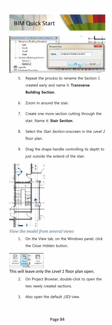
5. Repeat the process to rename the Section 1
created early and name it: Transverse
Building Section.
6. Zoom in around the stair.
7. Create one more section cutting through the
stair. Name it: Stair Section.
8. Select the Stair Section onscreen in the Level 1
floor plan.
9. Drag the shape handle controlling its depth to
just outside the extend of the stair.
View the model from several views
1. On the View tab, on the Windows panel, click
the Close Hidden button.
This will leave only the Level 1 floor plan open.
2. On Project Browser, double-click to open the
two newly created sections.
3. Also open the default {3D} view.
Page 84

4. On the View tab, on the Windows panel, click
the Tile button (or press WT).
5. Press ZA to zoom all windows to fit.
Zoom and pan to study the results of your work in each view. The following image shows the views stacked, but they will tile in a 2x2 configuration when using Window Tile.
File completed to this point: 17_Medical Center_Views.rvt
Page 85
Next Steps Now that you have completed a basic model, there is so much more that you can do with Revit. The next series of lessons contains lessons on a variety of topics including:
• Conceptual Massing and Schematic Design • Working with CAD files in Families • Running an Energy Analysis in the Cloud • Walls, Doors and Dimensions • Working with Rooms • Adding Stairs and Railings • Working with non-rectangular viewports • Text, tags and dimensions • Making modifications • Using Displace Elements • Using Materials • Creating a Cloud Rendering
To learn more:
Page 86