Embed Size (px)
Citation preview

MS2011072 Rev 0 10th
January 2012
Guide by Clinton Brown
Autodesk Inventor Tube and Pipe – Custom
Template Authoring
This is step by step guide to help you create a custom Tube and Pipe template,
or Company standard template for Tube and Pipe. Note that this is designed
for Advanced users with an understanding of projects and design data
MS2011072
Advanced CAD users, CAD Managers, System Administrators
For advice on shared design environments, please see the notes at the end.
To get started with creating your own Piping Standards, continue as described below, it is advised that you first
read through this tutorial, before attempting to modify your design data. It is also advised that you create a
backup copy of your current design data before proceeding, Tube and pipe specific design data is kept in the
following location by default C:\Users\Public\Documents\Autodesk\Inventor XXX\Design Data\Tube & Pipe in
shared environments, this location could be different, please refer to your project file.
Create a new blank Assembly, and save it. (For the purpose of this exercise, call it AssemblyName.iam)
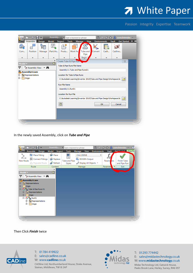
In the newly saved Assembly, click on Tube and Pipe
Then Click Finish twice

Now Delete Run01 in your browser (as shown above)
To modify your styles, click on the Tube and Pipe Styles Button

Create the new pipe standards as required, remember to fill in the required rules
Click on Save
Finish Tube and Pipe

Right Click on the Tube and Pipe Runs in the browser, click on iProperties. In the iProperties, click on the
Occurrence Tab, and unselect Adaptive (as shown below)
Click Apply

On the General Tab in iProperties, highlight the Location information and copy it to your clipboard (as shown
above)
Browse to this location in Windows Explorer
Copy the file called AssemblyName.Tube and Pipe Runs01.iam to your clipboard (AssemblyName is the name
you gave the original Assembly file)

Navigate to C:\Users\Public\Documents\Autodesk\Inventor XXX\Design Data\Tube & Pipe*
*If your project file accesses your design data from another location, browse there. A common set of Design data
should be used across design teams to ensure enforcement of standards
Paste AssemblyName.Tube and Pipe Runs01.iam into this folder
Rename the piping runs.iam to piping runs ORIGINAL.iam (this keeps a backup of the original settings)
Then rename the AssemblyName.Tube and Pipe Runs01.iam to piping runs.iam
Close the file in Inventor.
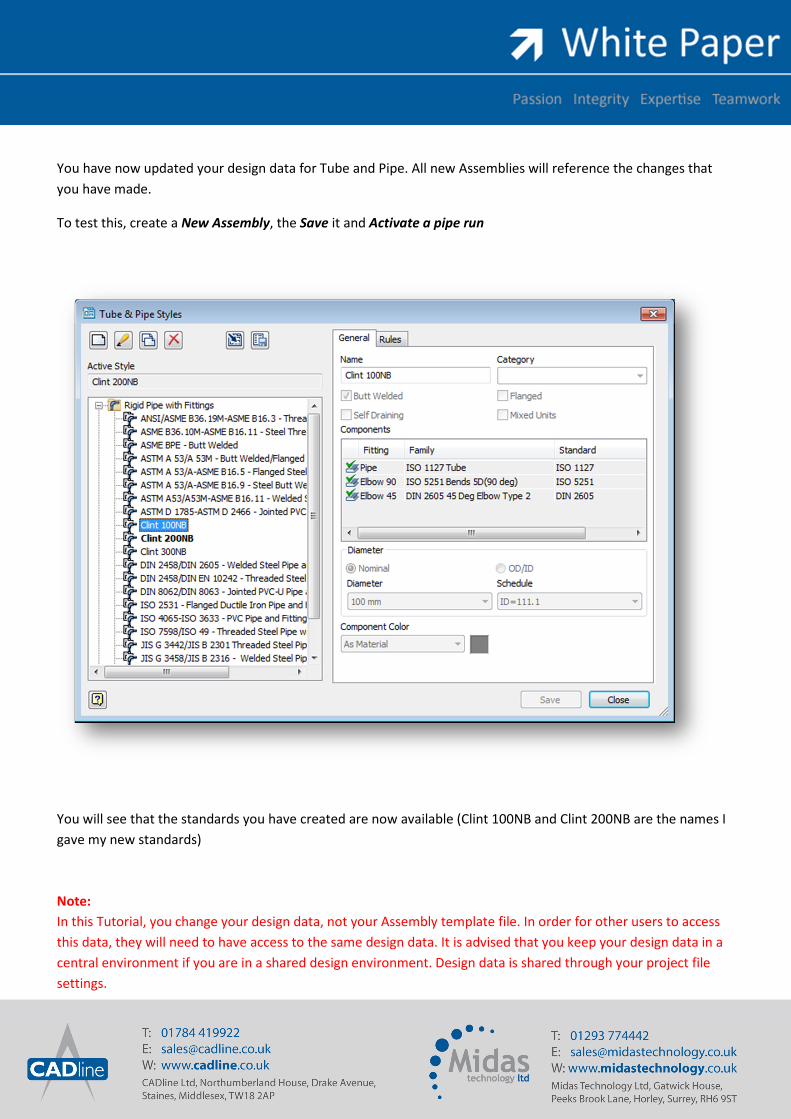
You have now updated your design data for Tube and Pipe. All new Assemblies will reference the changes that
you have made.
To test this, create a New Assembly, the Save it and Activate a pipe run
You will see that the standards you have created are now available (Clint 100NB and Clint 200NB are the names I
gave my new standards)
Note:
In this Tutorial, you change your design data, not your Assembly template file. In order for other users to access
this data, they will need to have access to the same design data. It is advised that you keep your design data in a
central environment if you are in a shared design environment. Design data is shared through your project file
settings.