Embed Size (px)
Citation preview

AutoCAD Topics by Chapter
Quick Start
Chapter 1: Starting to Draw
Chapter 2: Opening a Drawing
Chapter 3: Using Commands (44 & 50)
Chapter 4: Specifying Coordinates
Chapter 5: Setting up a Drawing
Chapter 6: Lines
Chapter 7: Curves and Points
Chapter 8: Viewing your drawing
Chapter 9: Basic Editing
Chapter 10: Advanced Editing
Chapter 11: Organizing Drawings
Chapter 12: Drawing Information
Chapter 13: Text (and Annotative Objects)
Chapter 14 & 15: Dimensioning
Chapter 16: Complex Objects
Chapter 17: Plotting
Chapters 18 & 19: Blocks and XREFs

1) Quick Start Chapter (adapted from AutoCAD Bible 2010)
a) Application Button - Upper Left
b) Quick Access Toolbar - Upper Left
c) Ribbon – Near top of screen
d) Layers e) Dynamic Input Tooltip (at cursor)
f) Command Line – near bottom of screen
i) COMMANDLINEHIDE to hide COMMANDLINE to get back
ii) Or undock and use Autohide
g) Status Bar - Grey bar along bottom of window. Turn things on and off by left clicking buttons.
Change settings by right clicking buttons. Use dropdown menus and menus buttons to change
settings.
h) Pick (Left Click = LC)
i) Short Cut Menus
i) Right Click = RC
ii) Shift Right Click = S-RC
j) Relative Coordinates - @
k) Absolute Coordinates - #
l) Splitting data with , or <T>
m) ORTHO Button on Status Bar
n) Layout Tab (Paper Space)
i) Title Block
ii) Viewport Border (1) Double-click inside to get at model (e.g., to PAN or Zoom)
(2) Double-click outside to get out of model
(3) Select border to get at Viewport properties, e.g., to change scale
iii) Page Border
o) View
p) Zoom
q) Text
r) Plotting
2) Chapter 1: Starting to Draw (adapted from AutoCAD Bible 2010)
a) Model Space – Any size! Draw objects at full scale.
b) Layout Tab (Paper Space) – Viewing model for plotting purposes
c) Status Bar i) Clean Screen Button – maximize drawing space, right end of status bar
ii) Down pointing triangle – select buttons, right end of status bar

3) Chapter 2: Opening a Drawing (adapted from AutoCAD Bible 2010)
a) 3 Ways from Application Button or Quick Access Toolbar
i) New
ii) Open existing drawing (DWG) – may need to change Files of Type in drop down list
iii) Open template (DWT) – may need to change Files of Type in drop down list
b) Drawings and templates have various characteristics
i) Drawing limits (determines extent of grid and zoom all) - Application ButtonDrawing
Utilities
ii) Units (metric or US) - Application ButtonDrawing Utilities
iii) Default settings
c) QNEW – set path to default template used when selecting a new drawing. Application
ButtonOptionsFile TabFile Setting Node
d) Making your own template – see book
4) Chapter 3: Using Commands
a) Use workspace switching drop down menu on status bar to switch between workspaces, such as
2D drafting & Annotation and AutoCAD Classic
b) Tabs/Panel Tabs, Ribbon
i) Tabs – Home/Insert/Annotate/ etc.
ii) Panel Tabs, drop down menus for each tab. E.g., for Home, the panel tabs are
Draw/Modify/Layers/…
iii) Ribbon – Commands that display in a ribbon below the row of tabs, for each tab. The full
ribbon includes the Panel Tabs.
c) Shortcut menus – RC or Shift-RC (S-RC) in drawing area
d) Toolbars – access to related commands
e) Palettes – access to related functions (tools & settings)
f) Command Line – type in commands, coordinates, values
i) F2 shows past commands
g) Dynamic Input Tooltip box – type near curser.
i) DYN button on Status Bar
ii) Use down arrow to see/select options
h) Typing Commands
i) All commands can be typed into command line or Dyn Input Tooltip box
ii) Some old or rare commands can only be accessed by typing
iii) Can use aliases, short nicknames for commands
i) Repeating Commands
i) Hit enter after completing the command and it starts over
ii) Press Spacebar while at Command line prompt and it starts over
iii) Before using command, type “multiple” and then select command. It will repeat until you
hit <ESC>.
j) Undoing a Command
i) Click backwards arrow button
ii) Type “undo” and you can specify how many operations to undo.
iii) Redo with forward arrow
k) Transparent Commands i) Can be used within another command (any command that doesn‟t select or create objects,
regenerate, or end a session)
l) Pan, Zoom,…

i) Pan – Press down scroll bar on mouse
ii) Zoom – Rotate scroll bar on mouse
iii) View Tab
iv) Buttons on Status Bar
m) Help in selecting points - Short Cut (Shift Right Click)
n) Getting Help - F1 or ? in upper right corner
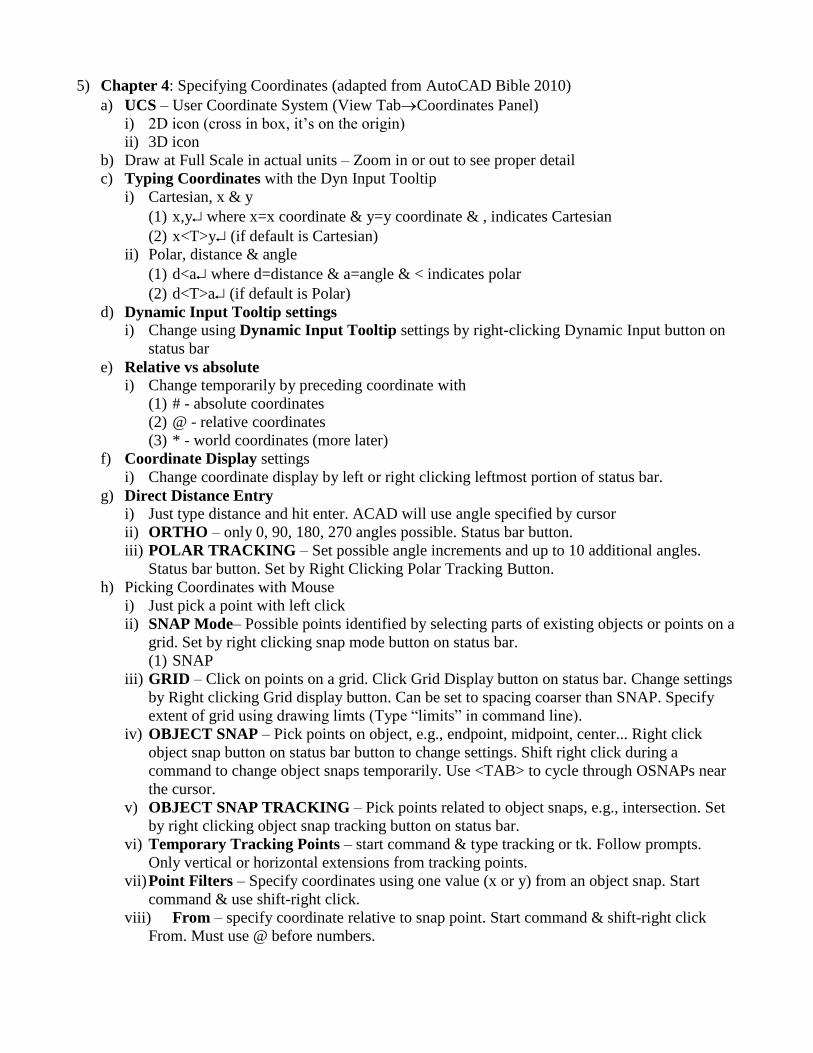
5) Chapter 4: Specifying Coordinates (adapted from AutoCAD Bible 2010)
a) UCS – User Coordinate System (View TabCoordinates Panel)
i) 2D icon (cross in box, it‟s on the origin)
ii) 3D icon
b) Draw at Full Scale in actual units – Zoom in or out to see proper detail
c) Typing Coordinates with the Dyn Input Tooltip
i) Cartesian, x & y
(1) x,y where x=x coordinate & y=y coordinate & , indicates Cartesian
(2) x<T>y (if default is Cartesian)
ii) Polar, distance & angle
(1) d<a where d=distance & a=angle & < indicates polar
(2) d<T>a (if default is Polar)
d) Dynamic Input Tooltip settings i) Change using Dynamic Input Tooltip settings by right-clicking Dynamic Input button on
status bar
e) Relative vs absolute i) Change temporarily by preceding coordinate with
(1) # - absolute coordinates
(2) @ - relative coordinates
(3) * - world coordinates (more later)
f) Coordinate Display settings
i) Change coordinate display by left or right clicking leftmost portion of status bar.
g) Direct Distance Entry i) Just type distance and hit enter. ACAD will use angle specified by cursor
ii) ORTHO – only 0, 90, 180, 270 angles possible. Status bar button.
iii) POLAR TRACKING – Set possible angle increments and up to 10 additional angles.
Status bar button. Set by Right Clicking Polar Tracking Button.
h) Picking Coordinates with Mouse
i) Just pick a point with left click
ii) SNAP Mode– Possible points identified by selecting parts of existing objects or points on a
grid. Set by right clicking snap mode button on status bar.
(1) SNAP
iii) GRID – Click on points on a grid. Click Grid Display button on status bar. Change settings
by Right clicking Grid display button. Can be set to spacing coarser than SNAP. Specify
extent of grid using drawing limts (Type “limits” in command line).
iv) OBJECT SNAP – Pick points on object, e.g., endpoint, midpoint, center... Right click
object snap button on status bar button to change settings. Shift right click during a
command to change object snaps temporarily. Use <TAB> to cycle through OSNAPs near
the cursor.
v) OBJECT SNAP TRACKING – Pick points related to object snaps, e.g., intersection. Set
by right clicking object snap tracking button on status bar.
vi) Temporary Tracking Points – start command & type tracking or tk. Follow prompts.
Only vertical or horizontal extensions from tracking points.
vii) Point Filters – Specify coordinates using one value (x or y) from an object snap. Start
command & use shift-right click.
viii) From – specify coordinate relative to snap point. Start command & shift-right click
From. Must use @ before numbers.

6) Chapter 5: Setting up a Drawing (adapted from AutoCAD Bible 2010)
a) Changing Drawing Units and Angles
i) Application ButtonDrawing UtilitiesUnits. ACAD uses exact units entered, but shows
measurement values at specified precision. Use higher precision than needed to avoid
errors.
b) Unit Types i) Decimal – 32.50
ii) Engineering – 2‟-8.50”
(1) Assumes inches if no „ or “
iii) Architectural – 2‟-8 1/2”
(1) Entered as 2‟8-1/2” or 2‟8-1/2. Confusing, displayed with moved „–„ and space
(2) Assumes inches if no „ or “
iv) Fractional – 32 1/2
(1) Entered as 32-1/2. Confusing, displayed with space
v) Scientific – 3.25E+01
c) Angles Types i) Decimal Degrees – 32.5
ii) Deg/Min/Sec – 32o30‟0”
iii) Grads (gradians) - 36.1111g (1 gradian = 1/100 of right angle)
iv) Radians – 0.5672r (2p = 360d)
v) Surveyor – N 57d30‟ E
d) Drawing Limits: type “limits” into command line
i) Draw at full scale, with proper units!
e) Set drawing from 0,0 to X,Y, where X and Y are just larger than what you need to draw.
f) Scales i) Figure out scale for printing at the start to properly size text.
ii) Depends on size of drawing and size of paper
(1) US – A, B, C, D, E
(2) Metric – A4, A3, A2, A1, A0
iii) Types and a few examples
(1) Architectural
(a) 192: 1/16” = 1‟
(b) 96: 1/8” = 1‟
(c) 48: 1/4” = 1‟
(d) 24: 1/2” = 1‟
(e) 12: 1” = 1‟
(2) Civil
(a) 120: 1” = 10‟
(b) 240: 1” = 20‟
(3) Metric
(a) 1000: 1mm = 10 meters
(b) 500: 1 mm = 5 meters
(c) 100: 1 mm = 1 meter
(4) Annotative Scales
(a) Object will automatically resize to proper scale when plotting
(i) Text, Dimensions & Leaders, Hatches, Blocks and Attributes.
g) Title Block i) Open drawing using a template with a title block
ii) Add a title block using InsertBlock PanelInsert Button
iii) Insert a new layout (Paper space) with an appropriate Title Block. Right click on a Layout
Tab and select From Template. Navigate to a template or drawing with a title block. Select
appropriate Layout and select OK.
iv) Draw a Title Block
h) Common Options i) Layers, Text Styles, Table Styles, Multileader styles, Dimension styles
i) Set Up Wizards j) Change the appearance of Model Space using Application Button→Options→Display Tab
and select the color button. For example, change the uniform background color to White and
model space will display as colored lines on a white background.

7) Chapter 6: Lines (adapted from AutoCAD Bible 2010)
a) Access from Home TabDraw Panel
b) Lines – simple line (introduced in quick start chapter)
i) Different line types covered later
c) Rectangles – Box (introduced in quick start chapter)
i) Opposite corner, Area (& length or width), Length & Width
ii) Rotation – enter rotation angle or two points that describe angle (e.g., along existing object)
iii) Elevation – Distance above xy plane to draw rectangle
iv) Thickness – Thickness of lines in y direction
v) Width – Width of lines in xy plane
vi) Chamfer – cut corners with straight line
vii) Fillet – round corners
d) Polygons – Look up if you need.
e) Construction lines – Temporary or Reference line that extends infinitely in each direction
i) Options – Horizontal, Vertical, Angle, Bisect, Offset
f) Rays – Temporary or Reference line that that extends infinitely in one direction
g) Linetype Scale –When using non-continuous lines (e.g., dashed), an improper scale can cause
the line to look continuous (e.g., if the scale is too small so you cannot see gaps between dashes
or if the scale is too big so a dash fills the screen) or even make it disappear (e.g., if the gap
between two dashes fills the viewing area). There are a number of system variables that can be
used to control how non-continuous lines are displayed. Use LTSCALE to change the global
scale of linetypes. Giving it a value greater than 1 makes the dashes and spaces bigger. If
MSLTSCALE = 1, Linetypes on the Model tab are scaled by the annotation scale. Set it to 0
and they are scaled to the model space “view scale”. If PSLTSCALE = 1, AutoCAD
compensates, showing the linetype at the same scale relative to paper space regardless of the
viewport scale, i.e. a linetype with dashes 0.25” long will have dashes 0.25” in any viewport
(regardless of viewport scale) and on the layout outside of any viewports. The first method
given is the recommended one. The others are included just in case.
i) Set LTSCALE, MSLTSCALE and PSLTSCALE to 1 (this is the default setting).
IMPORTANT: Type REGENALL in the command line if you don‟t see what you expect.
I recommend using the basic non-continuous linetypes, e.g., HIDDEN, CENTER, and
PHANTOM.
ii) Not RECOMMENED: Change Global Linetype Scale – Home Tab→Properties
Panel→Linetype Drop Down List→Other to open the Linetype Manager. If the “Show
Details” button is in the upper right, click it. Change the Global Scale Factor in the Details
area (bottom right). Smaller values compress linetypes, larger values expand. Only load
discontinuous linetypes that are not “2x” or “5x”, e.g., “BORRDER”, “CENTER”,
“DASHED”, and “HIDDEN”. Once you‟ve determined the scale you will use to plot,
change the global scale factor (GSF) accordingly, e.g., if you are printing at 1:200 enter 200
as the GSF, if you are using 1”=200‟ enter 2400 as the GSF.
iii) Not RECOMMENED: Change Linetype - Most come in short medium and long variations.
The change the linetype for a layer, <C> the layer in the Linetype column in the Layer
Properties Manager and select the desired linetype. Select the Load button to add more
linetypes.
iv) Not RECOMMENED: Change an object‟s linetype scale in its property box.
v) Not RECOMMENED: Change the scale of objects to be created using the Current Object
Scale – Home Tab→Properties Panel→Linetype Drop Down List→Other to open the
Linetype Manager. If the “Show Details” button is in the upper right, click it. Change the
Current Object Scale in the Details area (bottom right). Smaller values compress
linetypes, larger values expand. This will change the linetype scale for all subsequent
objects (it is best to leave it at the default of “1”).
h) Lineweights – Toggle the Show/Hide Lineweights button on the status bar to get AutoCAD to
show lineweights. Type LWEIGHT or LW into the command line to view the Lineweight
Settings box and slide the Adjust Display Scale to the right to exaggerate lineweights in
model space (to help you see differences). If a lineweight difference cannot be seen in paper
space, make the thicker line even thicker. AutoCAD cannot show a line thinner than one pixel
wide, if your viewport scale is high, you may have to use very thick lines in order see any
differences.
8) Chapter 7: Curves and Points (adapted from AutoCAD Bible 2010)
a) Access from Home TabDraw Panel
b) Circle i) 2P (two opposite points on circumference)
ii) 3P (3 points on circumference).
iii) Or chose center point and give radius or diameter
c) Arc – page 125: parts of an arc
i) Multiple ways to specify
(1) Start
(a) CenterAngle / Chord Length / End
(b) EndAngle / Direction / Radius / Center
(c) Second PointEnd
(2) CenterStart
(a) Angle / Chord Length / Endpoint
ii) When using Start/End/Radius to specify arc, a minor (default) or major arc is possible.
Make the major arc show by typing in a negative radius.
d) Ellipse – Cover on your own
e) Donuts – Cover on your own
f) Points – Identify coordinate with symbol or locate snapable object at coordinate
i) HomeUtilitiesPoint Style to change point symbol
ii) Turn on Node OBJECT SNAP to object snap to points

9) Chapter 8: Viewing your drawing (adapted from AutoCAD Bible 2010)
a) Regenerate to recalculate entire drawing. Rarely needed anymore. Type REGEN or
REGENALL in command line. It is needed to see non-continuous lines properly when viewport
scales are changed.
b) Redraw to refresh screen. Use it to get rid of any blips. Type Redraw in command line.
c) Pan - move drawing around screen or viewport.
i) ViewNavigate panelpan button or pan button on status bar
ii) Press scroll wheel and move mouse.
d) Zoom - Zooming does not affect the actual size of the object, just the viewing size.
i) ViewNavigate panelLowest command or button on status bar.
ii) Spin scroll wheel on mouse to zoom.
iii) Zoom options.
(1) Window - zoom into portion of currently viewable drawing by defining a rectangular
boundary.
(2) Dynamic - simultaneous zooming and panning. If there‟s an X at the cursor you can
move the white viewbox (i.e., pan). If there‟s an arrow, you can change the size of the
viewbox to select how much will be shown (i.e., zoom). <LC> to toggle between pan
and zoom. Hit enter to finish and see the new view.
(3) Scale - type a number followed by an x to zoom relative to current view or xp to zoom
relative to paper space units (e.g., 0.5x makes objects half current size, 2x makes them
twice current size).
(4) Center - set a new center of the drawing and a new relative magnification/height.
(5) Object - zoom in on selected objects.
(6) In zooms in 2x, while Out zooms out 0.5x, like the Scale option.
(7) All zoom out to the drawing extent or drawing limits, which ever is greater.
(8) Extents zooms to extent of drawing
(9) Previous goes back to previous display of drawing.
e) Steering Wheel – Steering Wheel button on status bar. All in one navigation tool.
f) Named Views - return to a particular view of a drawing. Good when working with large
drawings or drawings with lots of detail.
i) When you view a drawing in a manner you like, save the view by ViewNamed View in
View Panel, click new button and fill in the dialog box.
ii) To return to a saved view, select ViewNamed View, select the named view, click the
Select Current button and hit OK or Apply.
iii) If a drawing has named views, you can set it to open in a named view. Select Open from
the Application Button or Quick Access Toolbar, select the desired file then check the
Select Initial View check box. Click Open and choose the view you want to display when
the drawing opens.
iv) When working with a very large drawing, which might be slow to open in its entirety, you
can open only a Named View (e.g., a single plat out of an entire county) to speed things up.
Select Open on the Standard toolbar or File menu, select the desired file then click the
Open button‟s drop down menu. Choose Partial Open and select the desired named view
in the dialog box. You also need to select the Layers you want displayed. Select Load All
if you want all the layers. Finish by clicking Open.
g) Tiled Viewports - split screen into multiple views of same drawing. Any changes made in one
window are automatically updated in the other windows. The viewports are simply different
views of the same drawing. The default is one Viewport.

i) Create a viewport configuration by ViewViewports PanelSet Viewports button and
selecting the number of viewports desired or New Viewport in the submenu. You can even
give the configuration a name in the New Viewport dialogue box. This allows you to
restore the configuration at any time by selecting Named Viewports from the Viewport
submenu.
ii) If your drawing has Named Views you can specify one for each view in the New
Viewports dialog box. Click on the viewport in the preview pane and select the Named
View from the Change View To drop down list. If your drawing is in 3D, selecting 3D
from the Setup drop down list will create standard orthogonal views.
iii) You can subdivide any viewport by selecting it, going to the New Viewport dialogue box
and selecting Current Viewport from the Apply To drop down list. Otherwise a new
viewport configuration is applied to entire screen.
iv) Remove Viewports by selecting a New Viewport configuration or restoring a different
Named Viewport configuration.
v) Join a viewport to another by selecting Join from the Viewport submenu, selecting the
dominant Viewport, then selecting the Viewport to join.
h) Angled Drawings - sometimes a portion of a drawing is at an angle to the majority of the
drawing, e.g., an auxiliary view.
i) You can draw the angled portion using polar coordinates. If the POLAR TRACKING
button is selected you can find the correct angle by moving the cursor around. <RC> on
POLAR TRACKING then select setting to set the increment angles such that the desired
angle is easy to find. Then all you have to do to create lines is enter the length.
ii) You can change the User Coordinate System (UCS). The default UCS is the World
Coordinate System (WCS). The origin is X,Y equal to 0,0 with X to the East and Y to the
North. An angle of zero degrees is to the east. To rotate the UCS about the Z axis, select
View TabCoordinates Panel and select appropriate button. A positive value will rotate
counterclockwise. Specify a new origin, if needed, before or after rotating, by selecting the
Origin button.
iii) Finally, you could draw the entire object then rotate it.
i) Changing the User Coordinate System: There are a number of options, which can be accessed
from View TabCoordinates Panel.
i) World: applies the WCS, the default UCS, in which the origin is X,Y equal to 0,0 with X to
the East and Y to the North. An angle of zero degrees is to the east.
ii) Object: align the UCS to an object.
iii) Face: align UCS to face of 3D solid.
iv) View: align X, Y axis with current view.
v) Origin: used to set a new origin.
vi) Z axis Vector: Specifies direction of Z axis (3D only).
vii) 3 Point: Specify origin, X axis direction, and Y axis direction.
viii) X: rotate around X axis.
ix) Y: rotate around Y axis.
x) Z: rotate around Z axis.
xi) Named UCS to either save current UCS as a Named UCS or make Named UCS current.
Some common Named UCSs are included in the default settings.
xii) Change the UCS icon using the Hide/Show UCS Icon drop down list or and the UCS Icon
Properties button.
j) Isometric drawings are 2D drawings that look like a 3D drawing. Make lines and circles that
follow the specific angles of isometric drawings.

i) <RC> on SNAP (Button on bottom of drawing) and select properties. Turn on Snap and
Grid and select Isometric Snap.
ii) If needed, make the cursor larger using Application ButtonOptionsDisplay tab and
changing the Crosshair Size to 100. Click OK.
iii) Rotate through cross hair options (Isoplane left, Isoplane right, Isoplane top) by hitting F5.
Isoplane left shows a straight line and a line slanted upward from right to left. Use it to
make Isocircles in the left face. Isoplane right shows a straight line and a line slanted
upward from left to right. Use it to make Isocircles in the right face. Isoplane top shows
lines that form a cross. Use it to make Isocircles in the top face.
iv) Use the Line command and the snap grid to specify line direction (and length, if possible).
Isometric Snap must be selected.
v) Use the Ellipse command to make Isocircles. Set the cursor for the appropriate face using
F5. Select Ellipse→Axis, End from the Draw menu or Ellipse from Dashboard. <RC>
and select Isocircle. Select the center of the circle and enter or select the circle radius, <R>.
Isometric Snap must be selected.
10) Chapter 9: Basic Editing (adapted from AutoCAD Bible 2010)
a) Erase an object by selecting it and hitting the delete key or using the Erase command (Home
tabModify PanelErase).
b) Copy and/or Move Commands: There are numerous options available on the Modify Panel of
the Home tab. The object of interest can be selected before or after the command is selected.
One or multiple objects can be selected, then to get to next part of process. at the end as
well. You can select an object then right click to access many of these commands given below.
i) Move an object using the Move command. Specify a base and second point or a
displacement to specify where or how far the object moves. Don‟t forget, with the Dynamic
Input Tooltip (DIT) you can use the down arrow to select other options (e.g.,
displacement).
ii) Copy an object using the Copy command and following a procedure like the Move
command to specify where or how far. To Copy an object to another drawing select the
object then <RC> and select Copy with Base Point. Specify the Base Point on the object
(Object Snap works well), then switch to the second drawing, <RC> and select Paste, and
specify an insertion point.
iii) Rotate an object using the Rotate Command. Specify the Base Point about which to rotate
the object, then the Rotation Angle. Don‟t forget the “<” in front of the angle. A positive
angle causes counterclockwise rotation. The base point does not need to be on the object.
After selecting the Base Point, you can use the down arrow to select Copy or Reference
options. Use Copy to leave a copy of the object in the original position after rotating it. Use
Reference to create a reference angle (by selecting two points or typing it) then type or
select the new angle.
c) Resizing Commands: Some of the commands in the Modify menu can be used to resize
objects.
i) Scale an object using the Scale command. Specify the base point then type in the scaling
factor (e.g., 0.5 would make the new object half the original size) or use the down arrow to
select the same Copy and Reference options described for the Rotate command.
ii) Change a circle using the Change command. Changing a circle has the same result as
scaling it. You select a change point and the circle radius changes so the circle passes
through the change point. If more than one circle is selected, one must type in a new radius
for each circle in turn. Select the object and type “change” on the command line.
iii) Change a line using the Change command. Changing a line moves its end point (the end
closest to where you picked the line). If you select more than one line, Change moves the
ends nearest to the change point to the change point.
d) Selecting Objects
i) After getting a “Select Objects:” prompt, the selection options below can be selected by
typing the capitalized letters into the command line then hitting <R>.
ii) The Pick, Window (left to right drag), and Crossing (right to left drag) options are default.
Because you can keep selecting objects until hitting after a selection, you can use
multiple selection options as you select the desired objects.
(1) Pick an object by placing the cursor over it and <LC>.
(2) Use the Window option by clicking and dragging a box that contains the object(s) you
want to select.
(3) Use the Last option to select the last object created that is also visible in the current
view.
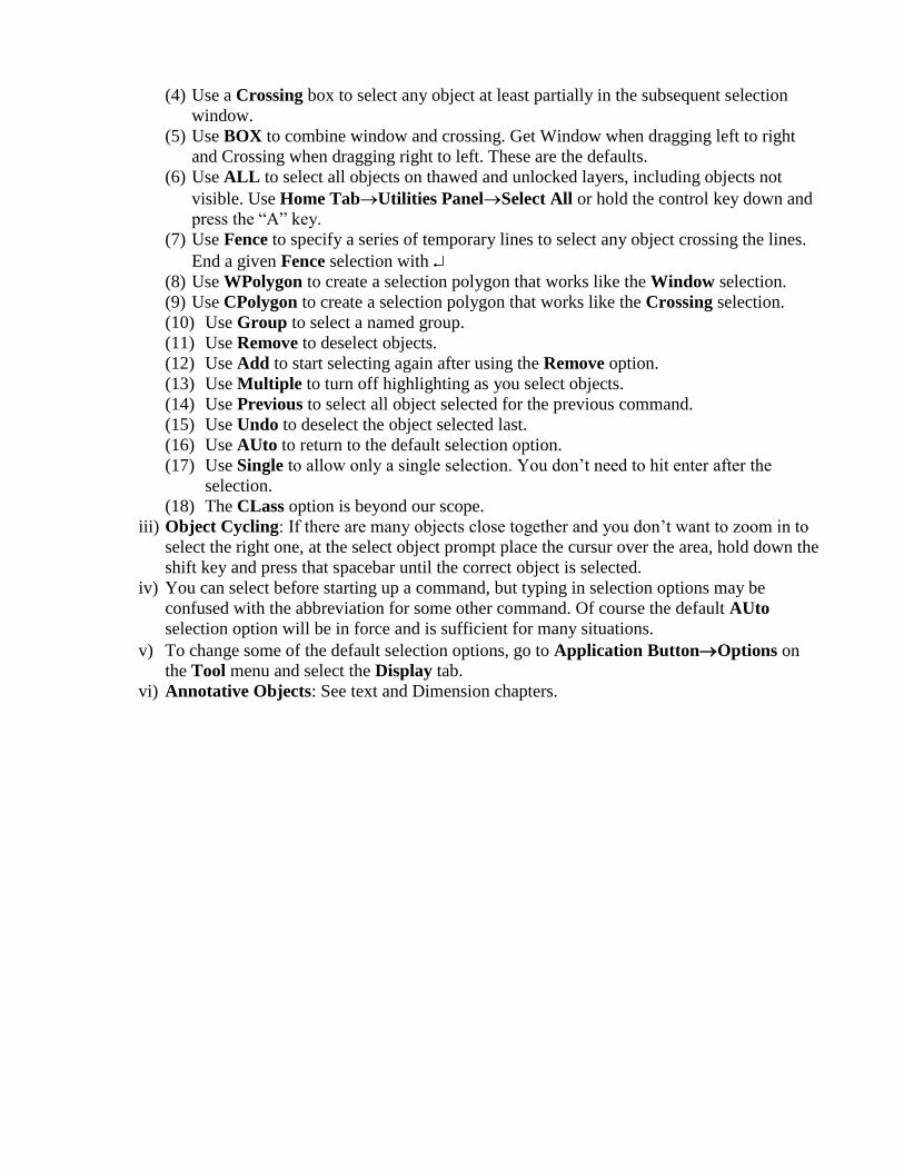
(4) Use a Crossing box to select any object at least partially in the subsequent selection
window.
(5) Use BOX to combine window and crossing. Get Window when dragging left to right
and Crossing when dragging right to left. These are the defaults.
(6) Use ALL to select all objects on thawed and unlocked layers, including objects not
visible. Use Home TabUtilities PanelSelect All or hold the control key down and
press the “A” key.
(7) Use Fence to specify a series of temporary lines to select any object crossing the lines.
End a given Fence selection with
(8) Use WPolygon to create a selection polygon that works like the Window selection.
(9) Use CPolygon to create a selection polygon that works like the Crossing selection.
(10) Use Group to select a named group.
(11) Use Remove to deselect objects.
(12) Use Add to start selecting again after using the Remove option.
(13) Use Multiple to turn off highlighting as you select objects.
(14) Use Previous to select all object selected for the previous command.
(15) Use Undo to deselect the object selected last.
(16) Use AUto to return to the default selection option.
(17) Use Single to allow only a single selection. You don‟t need to hit enter after the
selection.
(18) The CLass option is beyond our scope.
iii) Object Cycling: If there are many objects close together and you don‟t want to zoom in to
select the right one, at the select object prompt place the cursur over the area, hold down the
shift key and press that spacebar until the correct object is selected.
iv) You can select before starting up a command, but typing in selection options may be
confused with the abbreviation for some other command. Of course the default AUto
selection option will be in force and is sufficient for many situations.
v) To change some of the default selection options, go to Application ButtonOptions on
the Tool menu and select the Display tab.
vi) Annotative Objects: See text and Dimension chapters.

11) Chapter 10: Advanced Editing (adapted from AutoCAD Bible 2010)
a) More Copying and Moving Commands (Home TabModify Panel)
i) Use Offset to create a parallel object. If Offset is applied to a closed object (e.g., a circle or
polygon), it makes a concentric object. Choose Offset from Modify menu. Specify offset
distance: Type a distance or select two points the correct distance apart and hit . Select
object to offset. Select point on side to offset and hit to finish with rectangle command.
ii) Use Mirror to create a mirror image on an object (e.g., draw half of a symmetrical object,
then use Mirror to create remaining half). Choose Mirror from Modify menu. Click
object(s) to be mirrored. Specify first point of mirror line. Specify second point of mirror
line. Turn ORTHO on to help select a vertical or horizontal mirror line. If you don‟t want to
erase the original object, enter n or just if no is default.
iii) Use Array to copy an object multiple times into a rectangular or polar array (e.g., to copy a
window to make all the windows in a skyscraper or copy a spoke to make all of the spokes
in a wheel). Select the object to copy then select Array. Fill in the dialogue box. For polar
arrays, the initially selected base point will depend on the object selected, e.g., the center of
a circle.
iv) Use Align to move and rotate an object. Choose 3D Operation from the Modify Menu
then select Align from the submenu. Select the object(s) of interest then hit <R>. The
procedure is to select a source point on the object of interest then the related destination
point. This is done twice for 2D objects and 3 times for 3D objects. For 2D objects, hit <R>
at the prompt for a third source point. The final prompt asks if the realigned object should
be scaled to the alignment (i.e., destination) points.
b) More Resizing Commands (Home TabModify Panel)
i) Use Trim to trim an object on one side of another object or between two objects. First,
select the object(s) that specify where to trim then hit to go to the next step. At the
”Select object to trim” prompt you can use the down arrow to select a number of options. A
useful one is “Edge”. Select it and select “Extend” if you want to use an extension of an
object to trim. Finally, select the object(s) to be trimmed. Hit when finished.
ii) Use Extend to extend an object(s) to some boundary defined by other objects. Use it like
Trim.
iii) Lengthen can be used to lengthen or shorten open objects (e.g., lines, arcs,…) or increase
or decrease the included angle of arcs. The first prompt is to select an object. Selecting an
object simply gives its measurements (on the command line). Now use the down arrow to
select an option: DElta, Percent, Total, or DYnamic. You may need to use the down arrow
to specify what will be changed: length or angle. Select Delta and enter the desired change
in length (e.g., 2” would increase the length by 2” or <20 would increase the angle by 20o).
Select Percent and enter the desired percent change in length (e.g., 150 would increase the
length or angle by 50%). Select Total and enter the desired total value (e.g., 1‟ would make
the object 1‟ long while <20 would make the include angle 20o). Select DYnamic to be able
to simply move the cursor to lengthen or shorten. Hit and select the object. If you selected
the DYnamic option, you‟ll need to move the cursor and <LC> when the object is as
desired. Finish with <R>.
iv) Stretch is usually used to stretch or compress a group of objects. After choosing the
Stretch command, select the objects using a crossing window. Don‟t forget to go right to
left. Hit then select a base point on the objects then move the cursor and click or specify
the second point by typing. Finish with .

c) Construction Commands (Home TabModify Panel)
i) Break is used to delete a section of an object. Choose Break then click on the first break
point. If you selected the correct object, but not the correct break point, simply hit and
you get another try at selecting the first break point. Select the second break point and hit .
ii) Break at Point is used to break an object into two pieces.
iii) Use Join to join multiple objects. Choose Join then select the objects and hit . The objects
must be along the same linear, circular, or elliptical path.
iv) Chamfering creates corners from two nonparallel lines. After choosing Chamfer the
stored chamfer distance(s)/angle are displayed. To use them, simply select the two lines and
hit . Alternatively use the down arrow (or <RC>) to select Distance or Angle. If you
choose Distance, you must enter two distances then select the two lines to join with a
corner, finishing with . The values entered are the distances from the chamfer angle to the
intersection of the two lines. If either distance is zero you get a normal corner. If both
chamfer distances are non-zero you get a chamfered corner, with an angled line connecting
the two lines. If you chose Angle, enter the distance along the first line and the chamfer
angle to the first line, finishing with .
v) Filleting creates rounded corners. It connects lines, Polylines, circles, arcs, etc., even
parallel lines. Once you choose Fillet the current radius is displayed. Select two objects and
<R> to join them with a rounded corner using the displayed radius. Use the down arrow (or
<RC>) to choose options. Choose the Radius option if you want to change the radius.
Choose Polyline to apply the rounded corner to an entire Polyline.
d) A Revision Cloud is used to mark areas of a drawing that need revision or to draw attention to
revisions. Choose Revision Cloud from Home TabDraw Panel.
e) A Wipeout is used to hide objects to clear space for a note or to indicate that the covered
objects can be ignored. Choose Wipeout from Home TabDraw Panel then draw a Polyline
and hit . If you want to hide the boundaries of all Wipeouts on a layer, chose Wipeout and use
the down arrow (or <RC>) to choose the Frame option and select “Off”. If you want to convert
an existing Polyline to a Wipeout, choose Wipeout and select the Polyline option. Polylines
used as Wipeouts cannot contain arcs and must be closed.
f) Use Parameters to constrain an object‟s measurements (e.g., a circle must have a radius of 2)
or relationships with other objects (e.g., two lines must be parallel). Constraints are
dimensional or geometric. Dimensions can be constraints. Use the Parametric Tab.
g) Property Palette: Shows useful information about objects. Can be used to change properties.
<DC> an object or <RC> and select “Properties”. Use autohide and leave it up. The put cursor
over the Property Palette to show it. It will give information on whatever object is selected.
<DC>ing some objects will open a dialog box.
h) Grips can be used to move, rotate, scale, mirror, or stretch an object. Left Click the object and
you will see blue squares (Grips). Place the cursor on a Grip and wait for it to change color
then <LC> and move the cursor to change the object. <LC> again when you are done. Or,
<RC> a grip to enter the Grip shortcut menu.
i) Customize Grips from the of the Application ButtonOptionsSelection Tab.
i) Selection Filter: Use a Selection Filter to select all objects with certain properties, e.g., all red
lines. <RC> in the drawing and select Quick Select. Fill in the dialogue box. Use the Filter
command to make more complex filters than can be made using Quick Select. Type “filter”
on the command line to access the Object Selection Filter dialogue box.
j) Group: Combine objects into a Group by typing “group” at the command line . Complete
the Group dialogue box and hit OK. Select the objects in the group and hit . Blocks are
covered later.
12) Chapter 11: Organizing Drawings (adapted from AutoCAD Bible 2010)
a) Layers:
i) Have 4 states:
(1) On/Off - Off layers are invisible and cannot be plotted;
(2) Thawed/Frozen - Frozen layers are invisible, cannot be plotted, and are not regenerated
with the drawing until they are thawed;
(3) Unlocked/Locked - Locked layers are visible but cannot be edited; and
(4) Plottable/Not Plottable - Not Plottable layers cannot be plotted.
ii) Create a new layer by choosing Home Tab→ Layer Panel→Layer Properties Button
and click the New Layer Button (or <RC> on an existing layer and select New Layer) in
the Layer Properties Manager.
(1) Color (of lines), Linetype, and Lineweight can be assigned to a layer, in the layer
Property Manager (just LC on the correct layer row and property column, click Load
button and select desired colors, etc.).
iii) Move an object to a layer by selecting it and then selecting the layer in the layer drop
down menu in the Layer Panel in the Home Tab.
iv) Make a selected objects layer the current layer. Select object and LC the “Make
Object’s Layer Current” Icon in the Layer Panel in the Home Tab.
v) Show all layers or just the layers in use. In the Layer Properties Manager, use filter tree
panel on left to show all layers or just the ones in use. If the filter tree isn‟t visible, RC in
the Layer Properties Manager and choose Show Filter Tree.
b) Objects can be assigned colors, linetypes & lineweights separate from their layer. Select and
use the Property Toolbar or <RC> object and select properties.
i) ByLayer assigns the layer color (or linetype, etc.) to the object.
ii) ByBlock assigns the block‟s color (or linetype, etc.) to an object in a block.
c) Linetype Scale –When using non-continuous lines (e.g., dashed), an improper scale can cause
the line to look continuous (e.g., if the scale is too small so you cannot see gaps between dashes
or if the scale is too big so a dash fills the screen) or even make it disappear (e.g., if the gap
between two dashes fills the viewing area). There are a number of system variables that can be
used to control how non-continuous lines are displayed. Use LTSCALE to change the global
scale of linetypes. Giving it a value greater than 1 makes the dashes and spaces bigger. If
MSLTSCALE = 1, Linetypes on the Model tab are scaled by the annotation scale. Set it to 0
and they are scaled to the model space “view scale”. If PSLTSCALE = 1, AutoCAD
compensates, showing the linetype at the same scale relative to paper space regardless of the
viewport scale, i.e. a linetype with dashes 0.25” long will have dashes 0.25” in any viewport
(regardless of viewport scale) and on the layout outside of any viewports. The first method
given is the recommended one. The others are included just in case.
i) Set LTSCALE, MSLTSCALE and PSLTSCALE to 1 (this is the default setting).
IMPORTANT: Type REGENALL in the command line if you don‟t see what you expect.
I recommend using the basic non-continuous linetypes, e.g., HIDDEN, CENTER, and
PHANTOM.
ii) Not RECOMMENED: Change Global Linetype Scale – Home Tab→Properties
Panel→Linetype Drop Down List→Other to open the Linetype Manager. If the “Show
Details” button is in the upper right, click it. Change the Global Scale Factor in the Details
area (bottom right). Smaller values compress linetypes, larger values expand. Only load
discontinuous linetypes that are not “2x” or “5x”, e.g., “BORRDER”, “CENTER”,
“DASHED”, and “HIDDEN”. Once you‟ve determined the scale you will use to plot,
change the global scale factor (GSF) accordingly, e.g., if you are printing at 1:200 enter 200
as the GSF, if you are using 1”=200‟ enter 2400 as the GSF.

iii) Not RECOMMENED: Change Linetype - Most come in short medium and long variations.
The change the linetype for a layer, <C> the layer in the Linetype column in the Layer
Properties Manager and select the desired linetype. Select the Load button to add more
linetypes.
iv) Not RECOMMENED: Change an object‟s linetype scale in its property box.
v) Not RECOMMENED: Change the scale of objects to be created using the Current Object
Scale – Home Tab→Properties Panel→Linetype Drop Down List→Other to open the
Linetype Manager. If the “Show Details” button is in the upper right, click it. Change the
Current Object Scale in the Details area (bottom right). Smaller values compress
linetypes, larger values expand. This will change the linetype scale for all subsequent
objects (it is best to leave it at the default of “1”).
d) Lineweights – Toggle the Show/Hide Lineweights button on the status bar to get AutoCAD to
show lineweights. Type LWEIGHT or LW into the command line to view the Lineweight
Settings box and slide the Adjust Display Scale to the right to exaggerate lineweights in
model space (to help you see differences). If a lineweight difference cannot be seen in paper
space, make the thicker line even thicker. AutoCAD cannot show a line thinner than one pixel
wide, if your viewport scale is high, you may have to use very thick lines in order see any
differences.
e) Importing Layers and Linetypes – They can be imported from other drawings using the
DesignCenter (Insert Tab→Content Panel→DesignCenter Button).
f) Match Properties: You can transfer properties from one object to another. Home
Tab→Clipboard Panel→Match Properties.
13) Chapter 12: Drawing Information (adapted from AutoCAD Bible 2010)
a) Get drawing information by typing “Status” into command line.
b) Get object information by selecting the object and <RC> and select Properties. Or use Home
Tab→Properties Panel→List to get information in a different format.
c) Get coordinates of a point: Home Tab→Utilities Panel→ID Point.
d) Measure Distance, Radius, Angle, Area, or Volume using Home Tab→Utilities
Panel→Measure drop down list. e) Use Home Tab→Draw Panel→Multiple Points Drop Down List→Divide or Measure to
add points (or a Block) along an object
i) Divide – place points evenly about object, based on a specified number of segments.
ii) Measure – Place points every specified distance around object
f) Calculator - Home Tab→Utilities Panel→ Quick Calculator or View Tab→Palettes
Panel→Quick Calculator i) Can do unit conversions
14) Chapter 13: Text (adapted from AutoCAD Bible 2010)
a) Use Annotate Tab→Text Panel.
b) Standard Text prints at a single size. Annotative Text can print at any annotation scale that
has been assigned to it. Simple Text is OK for drawings that are only printed at one scale (just
make the Text the correct size in AutoCAD so that it prints correctly, e.g., a drawing printed at
1:2 scale needs Text of 0.4 inches if the printed text is to be 0.2 inches. Use annotative text if
you think a drawing will be used with multiple layouts printed at different scales.
c) Annotative Objects can be plotted at the desired size regardless of the viewport scale, if the
viewport scale used is one of the object‟s Annotation Scales.
i) Annotative Objects include Text, Dimensions, Leaders, Tables, Blocks, etc. See the
appropriate Chapters for specific information.
ii) The object must be declared as Annotative
(1) Text: use an Annotative Text Style or select Annotative on Annotative Tab→Text
Panel or make the text annotative using its Property Palette.
(2) Dimension: use an Annotative Dimension Style or select Annotative on Annotative
Tab→Dimension Panel or make the text annotative using its Property Palette.
iii) The current Annotation Scale will be assigned to a new Annotative Object. Change the
current Annotation Scale by clicking on the Annotative Scale down arrow in the Status Bar.
iv) Additional Annotation Scales can be added to an object. Select the object, RC in drawing
area and select Annotation Object Scale and pick Add/Delete Button. OR click the
Annotative Scale box in the Object‟s property palette.
v) Model Space Object size: The Annotative Scale determinse the size of annotative objects
relative to static objects.
vi) Paper Space (Layout) Object size: Plotting an Annotative Object in a viewport that has an
Viewport Scale equal to one of the object‟s Annotative Scales causes the object to print at
it‟s desired size. If the viewport scale is not the same as any of the object‟s Annotation
Scales, the object will not plot.
vii) Recommended: determine the possible viewport scales and make a style for the object that
is annotative and includes the appropriate annotation scales.
Exercise – Print Scale and Drawing Text Size
Make your own title block template, from the quick start drawing. Change the Firm Name and
Address to Your Name and Rowan University. Change the Project Name and Address to Your
Name, CEE Graphics, and Rowan University. Save it as a new template. Use it whenever you
print out drawings on 11 x 8.5” paper.
Open a new drawing. Import your title block. Set drawing limits to 0,0 to 8400,1200 (700‟,
100‟). Draw a rectangle that is 8000 by 1000. This represents a warehouse.
What scale will it be printed at? The paper size is A (11” x 8.5”). We will print in landscape
orientation. The title block drawing space is 8.3” x 7.9”. Our drawing is long in the x direction,
short in the y. The limit, then, will be the 8.3”. The exact scale (drawing just fits) is 1” to
8000”/8.3 or 1: 964. The nearest appropriate scale is 1:1000. Click on the viewport and add the
new sale using the Viewport Scale drop down list on the status bar.
Standard Text: If you want to include the text “Everett Warehouse” on the warehouse
drawing, what size does it need to be in the drawing to print at 0.25” at a 1:1000 scale? 0.25 x
1000 = 250”. Place the text at that size inside the warehouse, near the center-bottom. Use
Annotative Tab→Text Panel, and select a standard text style and give it a height of 250”
(Manage Text Styles in the Text Style drop down list). View in the paper space layout. What
if you need to print the various parts of the drawing at different scales? You could put text that
will be printed at different scales on different layers, in different sizes. Fortunately we have
annotative objects, new in 2008.
Annotative Text: You can assign Annotative Scales (one or more) to annotative text. The text
will then print out at a desired size at any of those scales. In Model space, LC on the
Annotation Scale drop down list (Status Bar) and select custom. Add 1:1000, 1:500, & 1:750
annotative scales. Now LC on the Annotative Scale and select 1:1000. Use Annotative
Tab→Text Panel, and select an annotative text style and give it a paper height of 0.25”
(Manage Text Styles in the Text Style drop down list). Type “Annotative Text” inside the
warehouse, center-top. The current annotative scale (1:1000) is automatically applied to it.
Select the text and RC in model space to add 1:500 to the object‟s annotative scales. In Model
Space, change the annotative scale from 1:1000 to 1:500 to 1:750 and back to 1:1000 (from
status bar). See the changes. Do the same thing in Paper Space (you can do this by double-click
in the view port and changing on the status bar or single-clicking on the viewport, opening the
property palette, and changing in the annotation scale box. See the changes. Finally, change the
viewport scale with the scroll bar.
15) Chapter 14 & 15: Dimensioning (adapted from AutoCAD Bible 2010)
a) Dimensions are made of:
i) Extension Lines - Extend from object to be dimensioned
ii) Dimension Text – Measurement value (length, degree…) and other descriptive text
iii) Dimension Line – Extends between the extension lines.
iv) Arrowheads – Mark intersection of extensions & dimension lines. Can be arrows, tick
marks, or dots.
b) Dimensions are Blocks and Associative (to an object or selected points).
c) Preparing to Dimension involves the following.
i) Create a dimension Layer, perhaps even a dimension layer for each separate drawing layer.
ii) Drawings created in pre-2002 AutoCAD need to have associative dimensioning turned on.
Type dimassoc at command line and 2 <R>.
iii) Set the text height for dimension layers (Annotate Tab→Text Panel→Text Style Drop
Down List→Manage Text Style) to zero if you want the dimension style to specify the
text height. Or set the dimension layer text height to over ride the dimension style text
height.
iv) Turn on OSNAP and set running object snaps (e.g., endpoint, intersection, center,…)
v) Create Dimension Style, if the standard style is not appropriate. It is common to make a
dimension style with a scale factor (see below) that makes dimensions show and plot
properly.
vi) Save dimension layer(s) and style(s) in drawing templates.
d) Create a new Dimension Style by selecting Annotate Tab and select the angled arrow in the
bottom right corner of the Dimension Panel. In the Create New Dimension Style dialogue
box you can name the new style, select the existing style it will be based on, and determine
which types of dimension the new style will apply to (usually All dimensions). Click the New
button to open the New Dimension Style dialogue box. There are a number of Tabs, including
i) Lines – Change dimension and extension lines
ii) Symbols & Arrows – Specify arrowheads, center marks, arc length symbols, jog angle…
Determine is a center mark or line is created with appropriate dimension commands.
iii) Text – Appearance, placement & alignment of dimension text
iv) Fit – set how dimensions work when they are applied to narrow objects or what to do when
text won‟t fit in the default position. Most importantly, this is where you set the Scale
Factor, which scales the dimensions, ideally, to the scale used to plot the drawing
v) Primary Units – Change format & precision
vi) Alternate Units – Check to display a second set of units in dimensions (e.g., English and
metric). Change format & precision of secondary units.
vii) Tolerances – Specify tolerances (how much deviation is allowed from exact measurement
when model is manufactured).
e) A number of Dimension types are included in the Dimension Panel
i) Use Linear to create a dimension along either drawing axis. Follow the prompts or <R> &
select the object to be dimensioned and follow the prompts. Options include
(i) MText to replace or add characters to the calculated dimension text (e.g.,
“TYP” for typical or “subject to final approval”)
(ii) Text to type replacement text on command line
(iii)Angle to change the text angle for the specific dimension
(iv) Horizontal/Vertical to force a particular orientation (rarely needed)
(v) Rotate for dimensions that are not along a drawing axis or aligned to an axis
(rarely needed)

ii) Use Aligned to align the dimension to an object (dimension line and measurement will be
parallel to object or a line through the extension line selection points.
iii) Use Baseline to create a series of dimensions that all start from one extension line. Select
Baseline and, based on the previous commands, you may be prompted to select a base
dimension or a second extension line origin.
iv) Use Continue to create a series of dimensions that are all attached. Select Continue and,
based on the previous commands, you may be prompted to select a continued dimension or
a second extension line origin.
v) Use Radius or Diameter to show the radius or diameter of a circle. Depending on the
Dimension Style, a center mark or line can be drawn automatically.
(i) Use Center Mark to add a center mark or line without adding a radius or
diameter.
vi) Use Jogged when the center of an arc or circle is located off the layout and cannot be
displayed in its true location
vii) Use Angular to dimension the minor or major angle associated with an arc or two lines.
(i) For Arcs, select the object, then move the cursor & <LC> to determine the type
of angle to measure & the position of the dimension text.
(ii) To dimension the minor angle, or an supplemental angle, associated with two
lines: select the lines, then move the cursor & <LC> to determine the type of
angle to measure & the position of the dimension text.
(iii)To dimension the major angle associated with two lines: <R>, then select the
vertex of the angle and the two angle endpoints. Use OSNAP and OTRACK to
select the angle vertex if the two lines do not meet.
viii) Use Ordinate to specify the X, Y, or Z coordinate of a point, e.g., the center of a circle.
ix) Use Leader to attach a note to an object or point. Down arrow to access the Leader
Settings dialog box.
x) Use Quick Dimension to dimension several objects at once. Select the objects to dimension
then down arrow and select the type of dimension. The same dimension type is applied to
all of the objects, or a baseline or continuous dimension is applied.
xi) Use Oblique to angle a dimension‟s extension lines. Select dimension object enter
oblique angle .
xii) Use Tolerance to specify allowable tolerances.
xiii) Edit a Dimension by selecting it then using <RC> to access a short cut menu that
includes editing options. You can also edit a dimension using the Property Palette.
f) Inspection Dimensions & Geometric Tolerances (new in 2008). See text.
g) Annotative Dimensions can print at any annotation scale that has been assigned to them.
i) See basic editing section here, or Dimensioning chapters in text and Chapter 17.
Exercise: Dimensions
Open the Warehouse drawing (from Annotative Text Example)
Standard Dimension: Make a Dimension Style called “Standard 250”. Annotate
Tab→Dimension Panel→angled arrow at bottom right, select “Standard” and <LC> new
button, name it “Standard 250”, <LC> Continue button, and make the text height 0.25 on the
Text Tab, on the Fit tab look at “scale for dimension features”, make sure “Use overall scale
of” is checked, and change the scale to 1000. Make a dimension of the North side of the
warehouse. Go back to the Dimension Style dialog box and modify Dimension 250 so the
precision is 0 (Primary Units tab). View change. (Be careful with setting precision, if you
make a mistake when drawing a shape, if the precision is set low, if the mistake might not show
up in the dimension. You can also set precision for an entire drawing.)
Annotative Dimension: This is a better option. Make a new style called Annotative 250, based
on the default Annotative style (see above). On the Fit tab look at “scale for dimension
features” and check “Annotative”. Then go to the Text tab and make the text height 0.25. Now,
when you make a dimension with this style, the current annotative scale will be applied to it.
Add more scales by selecting the dimension object and <RC> in the drawing. Change the
current annotative scale to 1:500. Make an Annotative 250 dimension and apply it to the South
side of the warehouse. Add the 1:1000 annotative scale to the dimension. In Model Space,
change the annotative scale from 1:1000 to 1:500 to 1:750 and back to 1:1000 (from status bar).
See the changes. Do the same thing in Paper Space (you can do this by double-click in the view
port and changing on the status bar or single-clicking on the viewport, opening the property
palette, and changing in the annotation scale box. See the changes. Finally, change the viewport
scale with the scroll bar.
ANNOUPDATE (typed in command line) to update existing annotative objects to the current
dimension (or text) style. Make a dimension current in the appropriate Style drop down menu
or dialog box.

16) Chapter 16: Complex Objects (adapted from AutoCAD 2010)
a) The Polyline command creates objects that combine lines and arcs. Choose Polyline from
Home Tab→Draw Panel. Select the starting point. Use the down arrow (or <RC>) to choose
one of the following options.
i) Select Arc to draw an arc. If Arc is selected, additional options becomes available: Angle
of arc, Center of arc, Direction of arc from start point, Line (draw a line segment), Radius
of arc, Second pt of arc, and Specify endpoint of arc.
ii) Select Close to close the Polyline from the last endpoint to the start point. Only available
after second point is chosen.
iii) Select Halfwidth to make a Polyline that is tapered by entering the starting and ending
halfwidth.
iv) Use Length to specify the length of the next segment, which will wither continue a
previous line segment or be tangent to a previous arc.
v) Select Halfwidth to make a Polyline that is tapered by entering the starting and ending
width.
vi) Specify next point (default) to create next line segment.
vii) Edit a Polyline by selecting Object → Polyline from the Modify menu. Then select a
Polyline. If you select an object that is not a Polyline, you are given the option of
converting the object to a Polyline. There are a number of options available, including an
option called Spline which converts the Polyline into something that is not quite a Spline,
as the curve may not pass through all of the Vertexes (see Spline command below). The
Vertexes of a Polyline are at the start and end of the segments used to make the Polyline.
The Edit Vertex option has its own set of sub-options.
b) The Spline command creates NURBS (Non-uniform rational B-spline) objects (Home
Tab→Draw Panel). A Spline is simply a smooth curve defined by a series of points. By
default the curve will pass through each point used to define the Spline. After you pick two
points, the following options will become available using the down arrow.
i) Close the Spline by connecting the last point to the first. You will need to specify the
tangent of the curve at the start point.
ii) Specify the Fit Tolerance, i.e., how closely the Spline comes to the points you pick.
iii) Specify next points (Default).
iv) Start tangent to specify the tangent to the Spline curve at the start point. You will be
prompted for the tangent to the last point as well. This creates an open Spline.
v) If you finish an open Spline by you will be prompted to specify the start and end tangent.
vi) Edit a Spline by selecting Object → Spline from the Modify menu. Then select a Spline.
c) Regions are 2D surfaces (Home Tab→Draw Panel).. They look like and are created from
closed Polylines (which can be circles, rectangles,…). They even look like closed Polylines,
but they have more properties (centroid, moments of inertia, and other mass-related properties).
Select one or more objects and hit . The closed objects will be converted to regions. More on
this when we get to 3D.
d) The Boundary command creates a Polyline or Region from an enclosed area (Home
Tab→Draw Panel). Complete the dialogue box, finishing by clicking the “Select Points”
button. Select points inside any area created by the intersection of any number of Polylines.
Multiple areas can be selected. Finish with . A Polyline or Region is created that matches the
boundary of each selected area.
e) Hatches are patterns that fill in an area (Home Tab→Draw Panel). Complete the dialogue
box. Edit a Hatch by selecting Object → Hatch from the Modify menu.
f) Gradients are fills that change from dark to light of from one color to another (Home
Tab→Draw Panel). Complete the dialogue box. Edit a Gradient using the Properties
Palette. Select the Gradient then <RC> and select Properties.
g) A Multiline is a set of parallel lines drawn with one command (Type MLINE in Command
Line). Create your own Multiline style by typing MLSTYLE into Command Line. Make sure
to save the Multiline and load it. You can also set it to be the current Multiline. To change from
the current Multiline to another loaded Multiline, use the down arrow to select STyle, then
down arrow again and . The will open a command line window that shows the names of the
current loaded Mutlilines. Type in the name of the one you want and . Alternatively, go back
to the Multiline Style dialogue box and use the Set Current button to select the one you want.
Type MLEDIT into Command Line to edit multilines.
h) Use the Sketch command to draw freehand, good for making contour lines. Type SKETCH
into the Command Line.
i) Tablet Command – For digitizing old paper drawings. See text.
17) Chapter 17: Plotting (adapted from AutoCAD 2010)
a) It is possible to plot from Model Space, but plots are most often done from Paper Space
(Layout Tabs).
i) You can show multiple views (Floating Viewports) of a model in a paper space layout, and
each view can be shown at a different scale
ii) Title blocks work best in a paper space layout, because each title block is for a given size
page.
b) Enter “layoutwizard” on the Cammand Line to easily make a new Paper Space Layout.
c) You can also create a new Paper Space Layout on your own: <RC> an existing layout tab to
access the layout short cut menu. On this menu you can select New Layout. You can also
access other options, including the Page Setup Manager (see below).
d) Change the new Paper Space Layout as you wish
i) Add a Title Block layer. Add a title block to this layer using Insert Tab→Block
Anel→Insert Button & picking a drawing with an appropriate title block (make one if
necessary). You can also draw the title block.
ii) Floating Viewports should be on their own layer, so, by freezing the layer one can make
their borders non-plottable. When you make a new layout using the layout short cut menu,
it will have one viewport. If you don‟t want the default viewport, select and delete it. Then
add as many Floating Viewports as you want using View Tab→Viewports Panel→New
Button & picking the appropriate option.
iii) Right click on the active layout tab and select Page Setup Manager to apply an existing
Page Setup to a Paper Space Layout, or create a new or modify an existing Page Setup.
Most of the options are easy to figure out. You generally don‟t need to apply a Plot scale to
a layout, as that is generally done for each viewport separately. The Shaded Viewport
Options only apply to model space.
iv) You can set model layer visibility separately within each Floating Viewport. Simply enter
Model Space within the viewport (<DC> inside viewport) and Use Home Tab→Layer
Panel→Layer drop down list to change the “Current VP Freeze property).
e) You can enter Model Space within a paper space Floating Viewport. This is often done to
Pan or Zoom the model within a particular viewport. <DC> within the viewport to enter
Model Space. Hit <Esc> until you get back to a cursor arrow then <DC> outside the viewport
to exit Model Space. Another way to do this is to select the Paper button (bottom of window)
while still in a layout. The button changes to Model. Select the Model button to return.
f) Access the Properties Palette of a Floating Viewport to change its scale. Gain quick access to
the Properties Palette of a viewport by clicking on its border, then <RC> and select
Properties.
i) The Property Palette of any object (including a Viewport) can also be accessed by selecting
the object, then selecting Home Tab→Angled arrow at bottom of Properties Panel.
g) Once you‟ve selected a Floating Viewport border (see above) you can <RC> to select the
Maximize Viewport option to temporarily expand the viewport to take up the entire window
(it will look like model space). <RC> again and select Minimize Viewport to return to the
normal view of the Paper Space Layout.
h) Save a layout as a Template for use in other drawings by selecting the layout‟s tab, typing
“layout” at the command line, then “sa” and again. Then complete the Create Drawing
File dialog box. Apply a Layout template to a layout by <RC> the layout‟s tab and selecting the
“From Template” option.
i) Use Plot Styles to assign plot styles to objects by color or name (Beyond scope of course).

j) Annotative Objects – Store representations at various scales and display according to scale of
specific viewport. To work, the annotative object needs to have been assigned any scales you
want it to print out as.
i) Examples include Text, Dimensions, Leaders
k) You can export AutoCAD dwg files in to a large number of other formats, including pdf, bmp,
jpg, and png.
i) Export a layout directly to a pdf using Output Tab→Export to DWF/PDF
Panel→Export Button. ii) Export other file types by typing JPGOUT, BMPOUT, PNGOUT or TIFOUT on the
command line. You can export from Model or Page Space. If you want to export a single
object from page space, <DC> inside the viewport first.
18) Chapters 18 & 19: Blocks and XREFs (adapted from AutoCAD Bible 2010)
a) Blocks: are groups of objects. Multiple blocks can be included in a given drawing and can be
inserted into other drawings. When a block is inserted into a drawing it is copied to the
drawing, unlike an Xref (see below). Blocks can be organized into Libraries (of parts or
symbols). Any drawing or symbol that is used multiple times should be managed in a block
library. Dynamic blocks have attributes that can be changed.
i) Use Home Tab→Block Panel→Create Button to create a block from a group of objects.
Or use Insert Tab→Block Panel→Create Button
ii) Explode a block using Home Tab→Modify Panel→Explode Button. This changes is
back to it original separate objects.
iii) Use Insert Tab→Block Panel→Insert Button to Insert a block. Browse to the drawing
containing the block. The insertion dialog box includes a number of options, including
rotation, flipping, and scaling (resizing). You can also use the Design Center (Insert
Tab→Content Panel).
iv) Save a block as a separate file by typing “wblock” in the command line.
v) Use Dynamic Blocks that have attributes that can be varied. This can reduce the number of
blocks you need to keep in your block library.
b) Xrefs: Include other drawings in the current drawing using External References (Xrefs). The
advantages of Xrefs over Blocks are (1) Xrefs keep your drawing smaller because they don‟t
become part of it (2) Xrefs are updated each time a drawing containing Xrefs is opened (3)
several people can use the same drawings as a Xref and (4) They can be attached and detached
easily. Access Xref commands on the Reference toobar. Use the same toolbar to attach and
edit images.
i) See what Xrefs are in your drawing using Home Tab→Palettes Panel→External
References Button or Insert Tab→angled arrow at bottom of Reference Panel.
ii) Attach an Xref using Insert Tab→Reference Panel→Attach Button.
iii) Edit an Xref by opening the actual dwg. The changes will be updated the next time you
open the drawing that references the Xref. Alternatively, select the Xref, then <RC> and
choose Edit Xref in Place or Open Xref.
c) Design Center: use Insert Tab→Content Panel→Design Center Button to grab Blocks,
Dimstyles, Layers, Layouts, Linetypes, Tablestyles, Textstyles, or Xrefs from other drawings.