Embed Size (px)
Citation preview

AutoCAD® MEP 2010 Advanced Tips and Tricks
Speaker Name – David Butts
MP214-1L The primary goal of this course is to take a deep dive into the more advanced features of AutoCAD MEP 2010, which will better assist users in meeting their design, documentation and standardization needs. In this session, the user will learn best practices and tips for fast methods for creating block-based multi-view parts and integrating them into a catalog library; and how to modify existing parametric connection geometry, such as a duct fitting, to match custom field conditions. The course comes with samples to help the user along the way. So join us for a fast-paced, information-filled session!
About the Speaker:
David is the training manager and senior technical engineer for the Building Solutions Division of Advanced Solutions, Inc. of Cary, North Carolina. His expertise is based on over 20 years of architectural and MEP engineering design and CAD management experience. He has an Associate of Applied Science in Architecture degree from Wake Technical College. David's Autodesk product specialties are in Revit® MEP, Revit Architecture, AutoCAD® MEP and AutoCAD Architecture. He is an Autodesk Architectural Desktop/AutoCAD Architecture Certified Expert, an AutoCAD MEP Implementation Certified Expert, and teaches at AUGI® CAD Camp and Autodesk University annually. Most recently he has also been working with external applications, such as the IES Virtual Environment, Green Building Studio® and Ecotect® product lines. He has been a part of the Autodesk reseller channel (formerly with CADRE Systems and currently with Advanced Solutions) since 1997.
Business email: [email protected]

AutoCAD® MEP 2010 Advanced Tips and Tricks
2
Introduction
Many engineering firms that are AutoCAD and AutoCAD LT users still depend on traditional CAD to complete their construction documents. In some cases, these firms create elaborate, and sometimes complicated, designs with plain AutoCAD. They may have seen the features and benefits of Autodesk’s Building Systems and AutoCAD MEP products over the years, but were wary of adopting it, due to the fact they did not know if the program could follow their design workflow. The user may also not be ready to make the change to Revit MEP for a variety of reasons.
There are also existing AutoCAD MEP and Building Systems users that for their own reasons are not ready to migrate to Revit. The types of projects, project sizes, user requirements and their CAD user’s skills and comfort levels, could be other factors that keep these users on their current version of these applications. They could simply be ready to get more out the program than they are currently using.
This document is geared towards CAD Managers and experienced AutoCAD MEP users that need to be able to recognize when these conditions exist, and how to use advanced features of AutoCAD MEP.
Note – to repeat the exercises, create the following folders under a folder on your local C: drive named ACADMEP2010:
• C:\ACADMEP2010\Custom • C:\ACADMEP2010\Profiles • C:\ACADMEP2010\Partbuilder

AutoCAD® MEP 2010 Advanced Tips and Tricks
3
Overview – Creating Custom Block-Based MvParts
AutoCAD MEP is based on creating two types of engineering elements – block-based targets and sources, and parametric connecting geometry. Targets are objects that receive power, fluids or air, while sources are the providers of these elements. Targets and sources are typical complex elements with few sizes, and include connections for piping, ducts, conduit, cable tray and wire. Load data can also be stored with these components. Autodesk uses a component called a Multi-View Part, or MvPart, to represent these types of MEP equipment. The MvPart can be an items as complex as a chiller, or as simple as an air terminal.
Some MvParts can also be parametric in nature, but the majority of components that are created as MvParts used a combination of 2D and 3D blocks to represent this object. This series of exercises will examine the following items:
- Creating 3D model and 2D symbol geometry that represents a part in plan and model views. - Defining the multi-view part and incorporating connection points. - Creating a separate catalog for custom parts created by the user. - Using third-party and web-based content to create custom parts.
The following sets of exercises are designed to help the user get more out of the application they are currently using, and provide a more detailed view of the program’s capabilities to the non-user. By explain how these tools impact the design process, the user can see how they will help reduce project drafting tasks, and add valuable data to their CAD files.
Exercise 1 – Creating Model and Symbol Geometry In this first exercise, the user should be able to create 2D plan symbols and 3D solids to represent a part in AutoCAD MEP. These components are the foundation of creating multi-view parts for the program.
Note: this exercise segment should take 5-10 minutes to complete once the user has become proficient with the steps listed.
Before getting started, Autodesk includes these tips to make the creation of parts simpler:
- Determine model dependencies. Analyze the model design to determine how features interrelate; then decide how to create the model.
- Work in a 3-dimensional (3D) view. Creating the model in a 2-dimensional (2D) view may lead to confusion.
- Do not use the EXPLODE command. Exploding a part deletes the part definition from the catalog. - AutoCAD object snaps can be used to assist in object selection - Leave the UCS icon on at all times

AutoCAD® MEP 2010 Advanced Tips and Tricks
4
Create a custom folder first to store your parts. This folder can be located on either a server or local hard drive. From Windows Explorer, create (or use) the folder C:\ACADMEP2010\PartBuilder. Locate your working drawings that are used to create parts in this folder. They can be discarded once the part is completed, or used to create additional parts.
1. To begin creating the symbol and model components, start a new drawing from scratch. This will eliminate the additional blocks, styles, etc. that comes preloaded with the default AutoCAD MEP templates, and keep the file clean and small. To start from scratch, type in STARTUP on the command line. Set the variable to 1, so the startup dialog is displayed. Next, type in NEW from the command line so the Startup dialog is displayed:
2. Select the second icon to start from scratch, and then choose either imperial or Imperial to create the part in the correct units (note: this exercise is completed in imperial units).
3. A new drawing will appear. Use the Save icon to save the drawing in the part builder folder, naming the file AHU Part Builder.
4. To turn on the Solids tab, right mouse click over the ribbon. Underneath Tabs, select the Solids tab. The solids tab will appear on the ribbon:

AutoCAD® MEP 2010 Advanced Tips and Tricks
5
5. Begin by selecting the Box tool. Specify the first corner as 0,0, and the second point as @6’, 4’. Define the height as 4’. After the height has been input, zoom to extents to see the part:
6. Use the view tab of the ribbon to change to a SW Isometric view:
7. This solid represents the body on an air handling unit. Next, solids will be added for the water and discharge components of the unit. From the solids tab, choose the box command again.
8. For a start point, type in 15,15,4’ (this is an absolute coordinate and specifies a location on the box relative to the base point of 0,0,0). For the second point, type in @18,18,4 to use a relative distance from the first point. The component will appear on the top on the unit:

AutoCAD® MEP 2010 Advanced Tips and Tricks
6
9. From the view tab, change to the Front view. Type in UCS, and select enter. Next, type in V and enter, to orient the working plane towards the front of the model:
10. From the solids tab, select the pulldown under the Box tool, and select the cylinder tool. Place the start point using a midpoint snap along the bottom edge of the front face of the model:
11. Once the center point is selected, type in a radius of 1” and a height of 2”. This will create the solid pipe connector for a chilled water connection. To move the connection up the face of the model, select the solid and change the Z elevation to 4”.
12. Return to the SW Isometric point of view. Type in UCS and select Enter twice to return the working plane to its original world coordinate.
13. Select the pipe connector, and then type in CP for copy. Pick a start point anywhere on the screen, and then drag the mouse towards the right side of the unit – type in 8” for the distance to create the copy. Select enter after the copy is created:
Select the midpoint here

AutoCAD® MEP 2010 Advanced Tips and Tricks
7
14. Once the solids have been created, the next step is to add points where connections can be made. Since a center snap can be used to locate the pipe connector, a point may not be needed for these connectors. Points will need to be created for the HVAC connections for the intake and discharge connections. To make the points visible, change the style by typing in DDPTYPE on the command line – select the point style highlighted below:
15. Select OK to continue. 16. To place a point, type in POINT on the command line. Select the midpoint of the left edge of the
connector box on the top of the unit:

AutoCAD® MEP 2010 Advanced Tips and Tricks
8
17. Move the connector to the right 9” using the move command (note: turn ortho on to make the point move in a straight line):
18. The point should now be centered on the connection. 19. To place the point for the intake, type in POINT, and then choose the mid point along the bottom
of the right side of the unit:
Select the midpoint here

AutoCAD® MEP 2010 Advanced Tips and Tricks
9
20. Select the point, and then use the properties palette to change the elevation to 2’. This will be an unsized connection, allowing the user to place any size duct connection needed.
21. The next step is defining the model as block. Type in BLOCK on the command line, and select enter.
22. Type in AHU-Custom-6x4-M for the block name, choose the select objects icon, and then choose all of the model geometry and points created. Make sure the base point is set to 0,0,0 and then select OK to continue. This block definition will be used as the model block for the part.
23. To create the 2D symbol block, type in REC on the command line and select enter. Choose 0,0 as the start point, and @6’,4’ as the end point
24. Draw a second rectangle with a start point of 15,15, and a relative distance of @18,18. Once the rectangle appears, draw two diagonal lines across the last rectangle, to represent the top HVAC discharge connection on the part.
25. To turn the visibility of the 3D model, select the Isolate Objects tool on the drawing status bar. Select Hide Objects, and then choose the 3D block definition. The 2D linework should remain visible:
26. Type in BLOCK on the command line, and select enter. Type in AHU-Custom-6x4-P for the block name, Choose the select objects icon, and then choose all of the linework visible. Make sure the base point is set to 0,0,0 and then select OK to continue. This block definition will be used as the 2D symbol block for the part
27. Choose the Isolate Objects tool on the drawing status bar, and then select End Object Isolation. The 3D model block will be visible.
28. The creation of the model and symbol block definitions needed to create the part is now complete. Both objects were created on Layer 0 and have bylayer characteristics for color, linetype and lineweight. These can be modified to BYBLOCK using the properties command for consistent appearance but is not required:

AutoCAD® MEP 2010 Advanced Tips and Tricks
10
29. Make sure the current view is an Isometric point of view, so the next steps can be correctly completed. Save the drawing.
END OF EXERCISE.
Exercise 2 – Defining the Part
AutoCAD MEP uses XML-based catalogs to track content for all types of components, from multi-view parts to parametric connecting geometry. In this first exercise, the CAD manager should be able to demonstrate how to add a catalog that separates the user’s custom content from the content that ships with AutoCAD MEP. By keeping this content separate, the user will be able to receive new content from Autodesk without having to be concerned with their content being lost or overwritten
Note: this demonstration should take 5-10 minutes to complete once the user has become proficient with the steps listed.
1. To being to define the part, change to the Manage tab and choose the Content Builder tool.
2. When the dialog appears, choose the MvPart domain, and then select the New Chapter icon. Add a chapter under All Installed MvParts (US Imperial) named Custom, and then add a sub-chapter named Mechanical:

AutoCAD® MEP 2010 Advanced Tips and Tricks
11
3. Once the chapters have been added, select the New Block part Icon:
4. Name the part AHU Custom 6x4. Select the description field, and the description will automatically populate from the name:
5. Select OK to continue. 6. On the behavior tab, choose Air Handling Unit as the type, M-MV-AIR_Handling_Unit as the layer
key alias (based on the AIA 256 Color standard – you will have a different layer key based on what style is set as the current standard), and Air Handling Unit as the subtype. While the user cannot add to the Type list, they can add to the subtype list if needed. Select Next to continue:

AutoCAD® MEP 2010 Advanced Tips and Tricks
12
7. On the Blocks and Names tab, select the add part size icon, and then select the model block for the model component:
8. After selecting the model component, select the 2D symbol block as the symbol block to use:

AutoCAD® MEP 2010 Advanced Tips and Tricks
13
9. Note the program will create the additional view blocks needed to be displayed based on point of view and display configuration. Select Generate Blocks to continue:
10. When the views dialog appears, select OK (unless the CAD manager really wants to customize the blocks, do not make any changes here). Select Next to continue.
11. All Parts require an image. Unless you’ve already created an image from the working block, use the Generate image tool to create a rough image of the model, This image can be replaced with a cleaner image later, but the image is required to continue. Select the Generate image option and then choose the generate image icon. Select Next to continue:
12. The connectors tab is next – and is what separates a multi-view part from an ordinary multi-view block or plain AutoCAD block. The connectors can be used to create parametric connecting geometry, and define the system connection between parts. Duct, pipe, conduit and cable tray can all have connectors assigned to a part. To create the connectors, start by right mouse clicking on the part name and choose Duct connector first:

AutoCAD® MEP 2010 Advanced Tips and Tricks
14
13. Name the connector Supply Air Discharge, and leave all of the other settings at their defaults, Select OK to continue:
14. Right mouse click again on the main part to add the following connectors (unless otherwise specified, leave settings as the defaults:
- Duct Connector – Air Intake: Unsized – True (this allows the user to define the size when
creating the duct) - Pipe Connector – Chilled Water Supply - Pipe Connector – Chilled Water Return

AutoCAD® MEP 2010 Advanced Tips and Tricks
15
15. After the connections have been added, right mouse click on Connector 1 under the AHU-Custom 6x4 part and choose Edit Placement:
16. The edit placement command will open a new interface that shows the part and the connection palette. All connections can be edited at once while the MvPart Builder palette is active. Active connections are shown in red while inactive connections are shown in blue. The active connector will also show up bold in the palette:
17. The command line will be prompting the user for a connection point, Type in P and enter to define the position of the connector. Use a node snap to select the node at the center of the discharge connection. A red connector will appear:

AutoCAD® MEP 2010 Advanced Tips and Tricks
16
18. Once the connection is placed, the symbol will include the shape of the connector (in this case rectangular). To set the size of the connection, go to the connector properties section of the palette – type in 18” for the connector width and height values:
19. Select the air intake connector at the top of the palette. To place the connection, select P for position, and snap to the connection point on the right side of the unit. Edit the placement values to match the image below:

AutoCAD® MEP 2010 Advanced Tips and Tricks
17
20. Since this connection is unsized, no size values will appear – the connection point will be indentified when the part is placed in the drawing by a plus sign grip.
21. Select the Connector 3 Chilled Water Supply connection. Repeat the same steps - for position, use a center snap to select the outside face of the left connector:
22. Change the default values to match the image below:
23. Select the last connector, using the same steps to place the connection point at the center of the right connector. Change the values on the palette to match the image below:

AutoCAD® MEP 2010 Advanced Tips and Tricks
18
24. Select OK to close the connector dialog. When a connector is expanded in the connectors dialog, the user will be able to see the properties of the connection:
25. Select Next to continue. 26. If the user wants to define additional properties for the part, they can select the Edit Properties
icon on the Properties dialog and add or remove catalog values as needed. Since this part will only contain one size, choose Finish to complete the command.
27. To test the tool, start a new drawing from an Aecb template. From the Home tab of the HVAC workspace, select the Equipment command. Browse to the catalog and locate the new part. Place an example in the drawing at an elevation of 0 and then select the part. Grips should appear at each connection; by moving your mouse over the connection, the user should see the information about the connection.
END OF EXERCISE.
Exercise 3 – Creating Custom Catalogs In the event a user creates a large number of parts, they may want to move their custom content to a separate location. In order to do this, the user catalog must contain at least one part, and the folder location must already exist. The MEP Catalog path will need to include this new path, and can only be added after the content is located in the new folder.

AutoCAD® MEP 2010 Advanced Tips and Tricks
19
Note: this exercise should take five minutes to complete once the user has become proficient with the steps listed.
Before getting started, Autodesk includes these tips to make the creation of parts simpler:
- Save a backup copy of the part catalogs before using Content Builder, in case you need to revert to the original catalogs provided with AutoCAD MEP. You can use a browser application, such as Windows® Explorer, to copy and paste the catalogs and their sub-folders to a new location.
- Use the order of the folders in the part browser as a guide to the steps involved in the creation process.
- Content Builder generates drawing views of your parametric part. The AutoCAD MVIEW command does not create associative views of your parts.
- From Windows Explorer in Windows XP or Vista, browse to the following folder (this is the default location as installed using the defaults for AutoCAD MEP):
C:\ProgramData\Autodesk\MEP 2010\enu\MEPContent\USI\MvParts\Custom
1. To begin creating the part, a new folder should be created and used for the custom content. This folder should be located on a server or local hard drive. The user must have full permissions and administrative rights to the folder. From Windows Explorer, create a new folder directly under the c:\ drive named c:\ACADMEP2010\Custom.
2. From the manage tab of the ribbon, select the Catalog Editor. In the Catalog editor dialog, select the New icon to create a new catalog:
3. In the new catalog dialog, change the part Domain to Multi-View Part. Name the new catalog Multi-View Parts – Custom. Match the description to the name, and change the catalog root directory to C:\ACADMEP2010\Custom (note: this folder must already exist on the system to be used):

AutoCAD® MEP 2010 Advanced Tips and Tricks
20
4. Select OK to continue and return to the catalog editor. 5. On the right panel, change the following values by double-clicking on the field: 6. Supplier Name – your company name; 7. Supplier URL – your company web address 8. Supplier Image – if you have an image file that can be used, select the image – make sure it’s in
a path that can be seen by all users. 9. Save the catalog. 10. Remain in the catalog editor. The next step is to copy the new part from its original location to the
new catalog. Open the existing catalog where the new part is located (see the previous path locations for the default catalog paths):
11. To copy the new part out of the main folder, expand the custom MvParts chapter to the Air Handling Unit Chapter. Right mouse click on the chapter and choose Copy:

AutoCAD® MEP 2010 Advanced Tips and Tricks
21
12. To re-open the new catalog, choose the File pull down menu, and then select the new catalog:
13. Once the new catalog is open, right click on the catalog and choose Paste. The Air Handling Unit chapter should appear:
AutoCAD® MEP 2010 Advanced Tips and Tricks
22
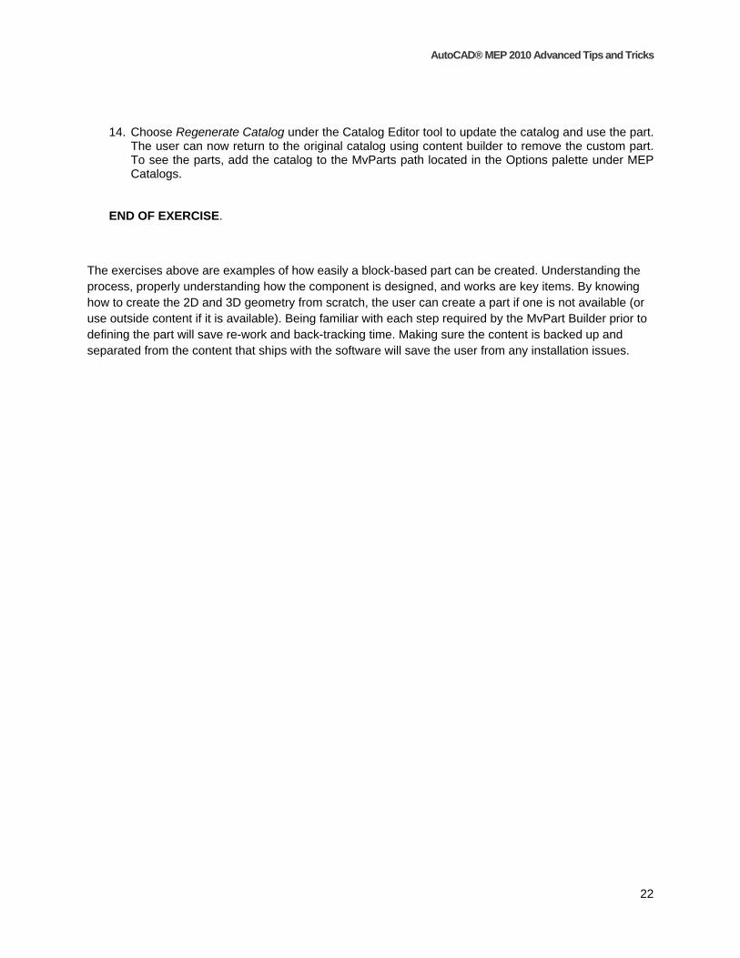
14. Choose Regenerate Catalog under the Catalog Editor tool to update the catalog and use the part. The user can now return to the original catalog using content builder to remove the custom part. To see the parts, add the catalog to the MvParts path located in the Options palette under MEP Catalogs.
END OF EXERCISE.
The exercises above are examples of how easily a block-based part can be created. Understanding the process, properly understanding how the component is designed, and works are key items. By knowing how to create the 2D and 3D geometry from scratch, the user can create a part if one is not available (or use outside content if it is available). Being familiar with each step required by the MvPart Builder prior to defining the part will save re-work and back-tracking time. Making sure the content is backed up and separated from the content that ships with the software will save the user from any installation issues.

AutoCAD® MEP 2010 Advanced Tips and Tricks
23
Chapter 2 – Modifying a Parametric Part - Exercises Exercise 1 – Selecting a Part and Creating a New File As a child most people were taught not to cheat – but this does not apply to CAD content. It is a smart behavior to use something that was already created and improve upon it – which is the main point of this exercise. Since creating parametric fittings from scratch is not a simple task, this exercise will explain how to choose the best part and create a new file to work in and modify to match the client’s conditions.
This exercise should take approximately 15 minutes to complete, and will take about 5-10 minutes to demonstrate to a client. This exercise also uses the AutoCAD MEP (US Imperial) profile, so the imperial catalog can be accessed. A similar part will be found in the US Metric catalog. As demonstrated in the previous exercises, the new part can be moved to a custom catalog after it is completed.
1. Begin by reviewing what the criteria are for the part. In this case, the client wanted a rectangular shaped, mitered duct elbow that would allow each branch of the elbow to be different lengths, and allow for user input into those lengths.
2. From the manage tab of the ribbon, open the Content Builder tool. Change the domain to Duct, and then select the Rectangular > Elbows category:

AutoCAD® MEP 2010 Advanced Tips and Tricks
24
3. In this case, the Rectangular Duct Mitered Transition Elbow US Imperial was chosen as the part to be modified, because it had the least amount of changes to be made to fit the criteria. This was determined using the Modify Part tool to examine the part, and review the model parameters and formulas used to make the part. To examine these properties, select the fitting in the main
panel, and then choose the Modify Part Size tool: 4. The Content Builder will open. The tool includes a palette that contains all of the tools for editing
the part:
5. To understand why this part was chosen, expand the modeling tab. Expand the SizeParameters subcategory:

AutoCAD® MEP 2010 Advanced Tips and Tricks
25
6. Each parameter represents a value used to create the part. For example, there are several values that include Len in the name – each one of these values represents a length of a component in the model. To see what the parameter is associated with, go to the modeling space view and note how there are “dimensions” in the model that include a parameter and a default value:
7. In the example above, LenA1 and LenA2 are the parameters that control the length of each branch of the fitting. This means that the part has two parameters already assigned that can be used to meet the criteria set forth by the client.
8. To see what controls these parameters, return to the content builder palette. Notice that both LenA1 and LenA2 are set to be equal to LenC1:
9. This tells the user that by changing the LenC1 parameter, it will change both legs. Since only one variable is controlling both segments, the solution is to create another variable, LenC2, that is visible in a catalog and allows user input. This variable will be assigned to LenA2 variable, and LenC1 can still control LenA1. (Note: LenA2 cannot be made visible from this location after is has been created, which is required in order for the user to be able to modify its values; therefore, it is easier to create another variable and assign its value to be equal to the existing parameter – visibility will be edited from the catalog later).

AutoCAD® MEP 2010 Advanced Tips and Tricks
26
10. To verify the values, right mouse click on any of the model parameters and choose Edit. In the Size Parameters dialog, scroll down to the LenC1 parameter – the description states what the parameter is used for:
11. Once our new part is created, this dialog will be used to create our new parameter. Select close to exit the dialog.
12. Before making any modifications to the part, the first step is to create a copy of the part. Choose
the second icon on the toolbar, Save Part Family As. 13. Name the part Rectangular Duct Mitered Transition Elbow Variable Tap, to reflect the
behavior of the part. Change the description to include the Variable Tap text, and make sure the chapter is set to Elbow. Note that new chapters can be added as needed to reflect custom parts:
14. Select OK to continue.

AutoCAD® MEP 2010 Advanced Tips and Tricks
27
15. Close the Content Builder tool to continue. To verify the part has been added to the catalog .XML file, open the Catalog Editor. Use the Open tool to open the Duct (US Imperial) catalog where the elbow is saved (the default location is: C:\ProgramData\Autodesk\MEP 2010\enu\MEPContent\USI\Duct. Expand the subcategories for Rectangular > Elbows, and verify the part exists in the catalog:
16. Select the close icon in the upper right corner to close the catalog editor.
The new file is created, and the user is ready to begin editing the part..
END OF EXERCISE.

AutoCAD® MEP 2010 Advanced Tips and Tricks
28
Exercise 2 – Editing the New Fitting
Now that the fitting has been copied and a new part created, review what tasks are needed to get the part to behave as desired:
- A new variable that controls the length of one branch of the fitting has to be created and assigned to the existing parameter,
- The options for the part need to be altered so the user can create any length value for the part. - The parameters should be tested to confirm they are working correctly
1. From the Content Builder dialog, open the part that was just created, and expand the Modeling category from the palette. Right mouse click on the Model Parameters section and choose Edit.
2. In the Model Parameters dialog, examine the properties of the existing variable, LenC1 – the user will create LenC2 to match these values. To create the parameter, right mouse click on Size Parameters, and then choose New. On the dialog, name the parameter LenC2, set the equation to be a value of 1 (since this is just a value, no equation is needed – this value will become part of an equation). Type in Body Tap Length 2 for the description. Check the units and make sure they are set to unitless:
3. Select OK to continue. Select Close to exit the Model Parameters dialog. 4. Under the model parameters section, the LenC2 parameter should now appear. To apply this
value to LenA2, right mouse click on the LenA2 parameter and choose Edit to open the model parameters dialog again.
5. Double click on the equation for LenA2 (the text LenC1) when ready, change the equation to read LenC2:

AutoCAD® MEP 2010 Advanced Tips and Tricks
29
6. After changing the parameter, hit enter to input the value. To test the parameter, select the parameter LenC2 - choose the Calculator tool and change its value to 4. Close the model parameters dialog and note the change:
7. Return to the Model Parameters dialog by right mouse clicking on the LenC2 parameter and choose Edit. Use the calculator to reset the value to 1. Close the dialog to continue (you can also select Undo to undo the change).
8. To allow the user to input and create sizes during the layout process, an option for allowing
custom sizing must be set. On the toolbar, select the options icon: 9. Check the box for custom sizing flag:

AutoCAD® MEP 2010 Advanced Tips and Tricks
30
10. This will allow the user to input any size needed to make the part. If the user wants the part to be selected as a fitting to be used during autolayout, the AutoLayout Flag can also be checked - leave this option unchecked.
11. Select the Save Part Family icon to save the changes. 12. To test the work so far, close the Content Builder, saving the changes if prompted (note: use the
close icon on the Content Builder palette to close both the palette and the drawing – do not close the drawing only).
13. In a new drawing started from an AecB template, draw a rectangular duct that is 24 x 24 in size per the example below – if prompted to select an elbow fitting, choose the Mitered elbow:
14. To modify the fitting, select the elbow and right mouse click – choose the Duct Fitting Modify option. Select the Rectangular Duct Mitered Transition Elbow Variable Tap from the part tab:
AutoCAD® MEP 2010 Advanced Tips and Tricks
31
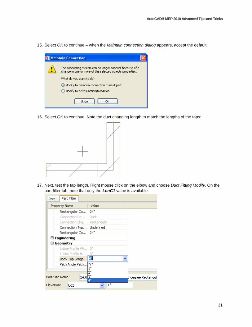
15. Select OK to continue – when the Maintain connection dialog appears, accept the default:
16. Select OK to continue. Note the duct changing length to match the lengths of the taps:
17. Next, test the tap length. Right mouse click on the elbow and choose Duct Fitting Modify. On the part filter tab, note that only the LenC1 value is available:
AutoCAD® MEP 2010 Advanced Tips and Tricks
32
18. This is due to the fact the catalog for the part needs to be edited to include the new length, so it can be adjusted as well. Change the LenC1 value to 4”, to see what changes on the part. Both branches will change to the same value, so know we know that simply changing the parameters does not mean the modifications are completed. The next exercise will examine how to edit the catalog so the values are available.
END OF EXERCISE.
Exercise 3 – Editing the Part Catalog
The part has been added, and parameters assigned to the model, but the part is not working as expected. It is important for the user to understand the role the catalog plays when creating parametric parts. Below are some of the tasks that must be completed so the part behaves correctly:
- Modify values as much as possible in the Catalog Editor. Some variables may be changed by opening the catalog with Notepad or an XML editor manually – while this is not the best practice, ALWAYS make a backup of the catalog should the user encounter problems.
- After making changes to the catalog, regenerate the catalog so any updated values will be added and verified in the catalog.
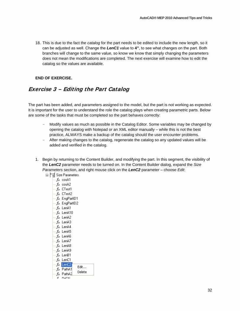
1. Begin by returning to the Content Builder, and modifying the part. In this segment, the visibility of the LenC2 parameter needs to be turned on. In the Content Builder dialog, expand the Size Parameters section, and right mouse click on the LenC2 parameter – choose Edit:

AutoCAD® MEP 2010 Advanced Tips and Tricks
33
2. Under the Size Parameters dialog, change from the Values editing tool to the Parameter configuration option:
3. Change its data storage value to List:
4. Change the visibility to True:
5. Select OK to close the dialog. Save the part family. 6. The next step is to add the default values to the part. Right mouse click on the LenC2 parameter
under size parameters and choose Edit. On the Size Parameter dialog (with the Values option set current), locate the LenC2 variable and pick its value:
7. Locate the Edit Values tool on the left size of the Size Parameters dialog: 8. Select the tool to open the Edit Values dialog. Use the add button to add the following values:
o 2 o 3 o 4

AutoCAD® MEP 2010 Advanced Tips and Tricks
34
9. Select OK to continue. Close the Size Parameter dialog, and then save the family and close the part.
10. The final step is to check the calculations for the part. In order to make sure the LenA2 formula is reading the correct values. Open the Catalog Editor, and then open the Duct (US Imperial) catalog (located in the folders specified earlier).
11. Browse to the Rectangular > Elbows section and locate the new fitting. Choose the plus sign to expand the options for the part, and choose Calculations:
12. In the right scroll over to the LenA2 Parameter. Review the default value that is still reading LenC1 – change the value by double-clicking on the cell, and then changing LenC1 to LenC2:

AutoCAD® MEP 2010 Advanced Tips and Tricks
35
13. Save the catalog. To make sure the catalog values are now updated, choose the Regenerate
catalog tool: 14. Select OK when the regeneration is finished and close the Catalog Editor. 15. Test the part – choose the duct fitting placed earlier, and observe how the user can now edit both
lengths and have different values for each branch.
END OF EXERCISE.
Editing parametric parts is not a common task, but understanding how to leverage the existing content to help create new parts is critical. Following simple guidelines and backing up existing catalogs is vital to the success of this task. Patience is also key, as the user will go through “growing pains” while learning the most advanced part of the application.