Embed Size (px)
Citation preview

7/26/2019 Auto Service and Repair - Martin W. Stockel
http://slidepdf.com/reader/full/auto-service-and-repair-martin-w-stockel 1/224
ó
o
ililil

7/26/2019 Auto Service and Repair - Martin W. Stockel
http://slidepdf.com/reader/full/auto-service-and-repair-martin-w-stockel 2/224
auto
serv¡ce
nd
repair
SERVIC¡NG
OCATI G
TROUBL
REPAI
ING
MODERN
UTOMOBT
ES
BASIC
KNOW-HOW
PPLICABLE
O
ALL MAKES
LL
MODELS
oy
MARTIN
W.STOCKEL
Industr ia l ducat¡on
Consutant
South Hollond
lll inois
THE
GOODHEART-WILLCOX
OMPANY
NC.
Publishers
7/26/2019 Auto Service and Repair - Martin W. Stockel
http://slidepdf.com/reader/full/auto-service-and-repair-martin-w-stockel 3/224
INTRODUCTION
This
text Tells
and
Shows
How
to
Serviee,
Locate
Trouble,
an d
Repair
Modern
Automobi les.
The
information
is
basic ,
andis
appl icable
to
all
models
of all
makes
of
cars.
AUTO
SERVICE
AND
RE AIR
teaches
Essentia l
sk i i ls : En-
courages
the Devel0pment
of
Good work
Habits.
I t Emphasizes safety.
AUTO
SERVICE
AND
REPAIR
is
comprehensive,
detailed,
an d
is profusely
il lustrated.
Many
of
the
drawings
were prepared
especialv
for
use in
this
text.
AUTO
sERVicE
AND
REPAIR
provides
instruction
as recom-
mended
by
the
standards
for
Automotive
serviee
Instructionin
schools.
I t
is
intended
for
beginners
who
need
a
sound,
thorough
foundation
in
fundamentals; also those now
engaged
in
automotive
service
and
reoair
who
want
to
increase
their
skil ls
and
step
up
their
earnings.

7/26/2019 Auto Service and Repair - Martin W. Stockel
http://slidepdf.com/reader/full/auto-service-and-repair-martin-w-stockel 4/224
CONTENTS
1
2
3
4
5
6
7
8
DETECTION
ND
REPAIR
119
9 CLEANING
EOUIPMENT
ND TECHNIOUES
139
19,
FRICTION
BEARINGS
149
11, ANTIFRICTION
EARINGS
163
12 TENGINEREMOVAL 179
1s,.
i'
-r+'-tr
13T
CYLINDER
HEAD,
VALVE AND
}
VALVE
TRAIN
SERVICE
185
14: CRANKSHAFT,
MAIN
BEARING,
FLYWHEELSERVICE
,. . . .225
15.
CAMSHAFT,
IMING
GEAR,CHAIN
SERVICE
243
16t SERVICING
NGINE
BLOCKS, YLINDERS,
¡NGS,
-
coNNECTtNG
RODS
261
: :>- ,
17)
ENGTNE
UBRICATION,
ENTILATION
SYSTEMS
295
18
ENGINE
ASSEMBLY,
NSTALLATION,
REAK-IN
311
COOLING
SYSTEM
ERVICE
319
BASIC
HAND TOOLS
PRECISION EASURI
G TOOLS
FASTENERS,OROUE
WRENCHES
GASKETS,
EALANTS,
EALS
TUBING
AND
HOSE
WIREAND W¡RING
JACKS,
IFTS,
PULLERS,
RESSES,
HOLD¡NG
FIXTURES
107
SOLDERING,
RAZING,
WELDINGCRACK
7
25
39
59
73
93
E$-
19
2A
FUEL
SYSTEM
ERVICE
7/26/2019 Auto Service and Repair - Martin W. Stockel
http://slidepdf.com/reader/full/auto-service-and-repair-martin-w-stockel 5/224
71
¡GNITION
SYSTEM
ERVICE
22 BATTERY,
GENERATOR,
EGULATOR,
STARTER
SERVICE
23
TUNE-UP, NGINE
SYSTEMS
ROBLEMDIAGNOS]S
24 CLUTCH
SERVICE
25
MANUAL
TRANSMISSION,
VERDRIVE,
FOUR-WHEEL RIVESERVICE
431
485
517
26
27
28
29
30
31
32
33
34
35
36
37
AUTOMATIC
RANSMI
SIONSEBVICE
PROPELLER HAFT,
UNIVERSAL
O¡NTSERVICE
DIFFERENTIAL,
XLE, SEAL,
HOUSING ERVICE
BRAKESERVICE
WHEELS, EARINGS,
IR
ES
STEERING. USPENSION
YSTEMS
ERVICE
AIR coNDITIONINGSYSTEM ERVICE
EXHAUST
AND
EMISSION ONTROLSERVICE
. . .
.
CAREER
OPPORTUNITIES
N
AUTOMOTIVEFIELD
METRICTABLES
GLOSSARY
F
TERMS
INDEX
53 5
575
599
615
647
689
719
763
789t:
817
821
829
851
:

7/26/2019 Auto Service and Repair - Martin W. Stockel
http://slidepdf.com/reader/full/auto-service-and-repair-martin-w-stockel 6/224
o
-¡
{
a
o
N
F\
o
o
o
o
q
I
0
o
a
o
o
o
o
o
6
o
-E
¡t
D
,
ú
o
E
o
]
E
U

7/26/2019 Auto Service and Repair - Martin W. Stockel
http://slidepdf.com/reader/full/auto-service-and-repair-martin-w-stockel 7/224
Chapter
BASIC ANDTOOLS
I -:-:s
chapter
wil l
c
over
the identif icat ion
*,mri
:se of basic
hand tools.
There
are
many
¡r:e: :ools
of a
rnore specialized
nature
which
a:e : : :ed
by' auto
meehanics.
These wil lbe
il lus-
tra;: j
ard discussed
in
the chapters
dealing
with
i5e
;e:r:ce
procedures in which they are
used.
TMLS ARE IMPORTANT
=.T:ng
available
for use
when needed,
awide
sae
:,::-o-
of quality tools
will
make
your work not
rmir
-ore
effect ive,
but faster.
The tools
wil l
eumrle you
to
quickly
perform
any
of the
great
¡r-t , . .e-
of
jobs
encountered
by
the mechanics.
l1¡e
cost
of labor
is high, and
in
fairness to
[,m.-. :
c:slomer and
garage,
a
mechanic cannot
a-ff:r: :o waste
time
working
with
an
inadequate
$ei*e:c4
of tools.
EiliJNT
OP
OUALITY
TOOLS
li
¡c:
are, or
plan
to become
a
professionatr
m*::¿:-:c,
rule out
inferior tools.
The cheaper
,g :ai:s
re
usually
made of
poor
material,
and
a-¡e
-5ek
and
thus cumbersome
to
handle.
They
m':- '
i='l
sooner,
slow down
your work and,
du e
i,r
; , : , : r
i: r lshing,
wil l
be
harder
to
clean.
T: 'c
qrality tools are made of alloy
steel
*,md
s:e
carefully
heat treated
to impart
great
wl lre:::h
a¡rd long wear.
They will be
less
bulky
mri
r:1]
have a smooth
finish that makes them
e*É-r
3n :he
hands and
quick to
clean.
The work-
:mlg
s-:rfaces
will
be made to
eloser
tolerances.
fr,s¡¡e:r parts
and
facilities
will
be available
and
tine :oois ¡ri.ll be guaranteed.
lAe:e
are a number of
manufacturers
that
prr scnee
excellent tools. Selection
of
a specific
lfirrs:lÉ
r:st be
left
to the
individual
mechanic.
$'Flm}[BER:
The
init ial
cost
of
good
tools
¡m,nr'
'e high but
considering
pride
of
ownership,
úe-mldablüty,
life span and
ease
of use and
ciɡ.: iqg,
they are,
in the
end,
less
expensive
rfosr=
:ools
of low
quality.
PROPER
CARE
IS ESSENTIAL
Fast,
eff icient
work
and confusion cannot
exist together.
Keep your tools
clean,
orderly
and near at
hand. A roll type of
cabinet,
in
combination
with
a
tool
chest
and
tote'l, t ray
(a
small tray,
containing
a
few selected tools,
that may be placed right at the job) wil l provide
proper
storage and accessibi l i ty . See
Fig. 1-1.
Fig. l-1. A
good
way to store
rools..( foo/s ore sf iown
arronged
lor disploy;
normolly they Íit neotly
into
drowers.)
(Snop-On
ools Corp.)
Place
delicate
measuring tools
in
proteetive
cases. Separate
cutting
tools
such as
fi les,
ehisels,
dril ls,
etc.,
topreventdamage
tocutting
7

7/26/2019 Auto Service and Repair - Martin W. Stockel
http://slidepdf.com/reader/full/auto-service-and-repair-martin-w-stockel 8/224
Auto Service
ond
Repqir
edges.
Tools
subject
to rusting should
be lightly
oiled.
Place heavy tools by themselves
and
in
general,
atiempt
to keep the
most
frequently
used
tools handy.
Keep
sets such as sockets,
open end, and
box
end
wrenches together.
RE -
MEMBER: THE LITTLE TIME IT
TAKES TO
KEEP YOUR TOOLS CLEAN AND ORDERLY
WILL BE
GREATLY
OFFSET BY
THE TIME
SAVED
ON
THE JOBJ
HAMMERS
Ball
peen, plastic
tipped, brass and
lead
hammers
should be included
in everymechanicrs
selection.
Various
sizes
of each are
desirable.
The ball
peen
is
used
for.general striking,
riveting,
gasket
cutting,
etc., and
the
plastic,
lead
and brass hammers are
used to
prevent
marring
part
surfaces.
When
using a
hammer,
grasp the handle firmly, hand near to the handle
end, and strike
so the
face
of
the hammer en-
gages
the
work
squarely,
Fig.
1-2.
Fig.
l -3.
Cfi ise/s.
1-Hol l
round. 2-Diamond,
3-Cope. 4-Flot.
i t as far from
the top as
practieal.
This wil l
protect
your fingers
somewhat if
the
hammer
slips
from
the
chisel
head. For heavy
hammer-
ing, a
chisel
holder should be
used,
Fig.
1-4.
Fig.
l -4.
Chisel
holde¡.
n use tñe handle
should be kept t ight.
Keep
the
cutting
edge sharp and
the top
chamfered
(edges
tapered) to
reduce the
possi-
bil ity
of small chisel
segments breaking off and
flying
outward. WEAR GOGGLES WHEN
USING
A
CHISEL,
Fig.
1-5.
PUNCHES
Starting,
drift
and
pin punches
are essential.
A few sections
of
round
brass stock in
varying
Fig. l -2.
Hammers.
Bol l
peen.
Plostic fípped.
8ross.
DANGER.I
USE A
HAMMER
WITH CARE.
DO NOT
SWING
IT IN A DIRECTiON
THAT
WOULD ALLOW IT TO
STRIKE
SOMEONE
IF
IT
SLIPPED
FROM
YOUR
GRASP.
MAKE
CERTAIN THE HANDLE IS TIGHT IN THE HEAD
AND THAT THE HANDLE IS CLEAN ANDDRY.
CHISELS
Chisels are used for
jobs
such
as
eutting
off
rivet heads, bolts
and
rusted nuts, Flat,
cape,
diamond,
half-round
and
rrrivet
bustertt
ehisels should be
available,
Fig.
1'3.
Hold
a
chisel seeurely
yet
not tightly. Grasp
SHARP
EN
ED
Clrisel
or left is dangerous fo
use.
chamfering and shorpening,
s sfiown
Some cfiisel,
ofter
ot
r ight.
4
Fis.
l -5.
7/26/2019 Auto Service and Repair - Martin W. Stockel
http://slidepdf.com/reader/full/auto-service-and-repair-martin-w-stockel 9/224
Bosic
Hqnd
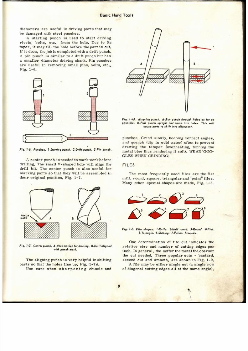
diameters
are
useful in driving
parts
that may
be
damaged
with
steel
punches.
A
start ing
punch
is used to start driving
rivets,
bolts, etc.,
from
the hole.
Due
to
it s
taper,
it
may
fi l l
the hole before the
part
is out.
If
i t does,
the
job
is
completed
with
a drif t
punch.
A pin punch
is similar to
a
drif t
punch
but
ha s
a smaller diameter driving sha nk. Pin punehes
are useful in removing small
pins,
bolts, ete.,
Fig.
1-6.
Fig.
l-6.
Punclres.
l-stort ing
punch.
2-Dri l t
pun h.
3-Pin
pur.h.
A
center
punch
is
neededtomark workbefore
dril l ing. The
small
V-shaped hole wil l
align the
dril l
bit . The
center
punch
is also useful for
marking parts
so that they wil l be
assembled
in
their original posit ion, Fig. 1-7.
Fig. l:7.
Center
puncfi.
A-Workmo¡ked or drilling.
B-Drill
aligned
with
pvnch
mork,
The
aligni.ng
punch
is
very
helpful in
shifting
parts
so
that
the
holes
line up,
Fig..1-7A.
Use
eare
when sharpening
chisels
and
Tools
Fig. I-7A. Aligning punch. A-Run punch throughholes os fo¡ os
possible.
B-Pull
punch
upright and
Íorce into
holes.
This
wil l
couse
ports
to
shilt into olignment,
punches.
Grind
slowly,
keeping
correct
angles,
and
quench
(dip
in
cold
water)
often
to
prevent
drawing the temper
(overheating,
turning
the
metal
blue thus rendering
it soft). WEAR-GOG-
GLES
WIIEN GRINDINGJ
FILES
The
most frequently
used
files
are
the
flat
miLl, round, square, triangular and point fi les.
Many
other special
shapes are made,
Fig.
1-8.
s
c3'3
Fig. l-8.
Fi le shopes,
l-Knile.
2-Holl
¡ound,
3-Round.
4tFlot,
5-Triangle. 6-5Iitting. 7-Pilla¡. 8-Sguore.
One
determination
of
fi le
cut
indicates the
relative
size
and
number of
cutting edges
per
inch. In
general,
the softerthe metalthe
coarser
the
cut needed.
Three popular
cuts
-
bastard,
second
cut
and
smooth, are
shown in Fig.
1-9.
A file
may be
either singl.e
cut
(a
single
row
of
diagonal
cutting edges alL at
the
same
angle),
+,

7/26/2019 Auto Service and Repair - Martin W. Stockel
http://slidepdf.com/reader/full/auto-service-and-repair-martin-w-stockel 10/224
Auto
Service ond
Repcir
Control
the
fi le
to
prevent
roeking
(unless
fi l ing
round stock).
It takes a
great
deal of
practice
to become
expert at
fi l ing. A fi le,
in
the
hands of
a
professi.onal,
can
do amazingly
aecurate
work.
Keep the
file
clean and
free of oil.
Use
a
file
eard (special wire brush) occasionally to clean
the
.
eeth.
Regular blackboard
chalk
may
be
rubbed
into
the
file
to
help
prevent
clogging.
Fig.
1-9. Three
di l ferent
f i le cuts
-bostord,
second
cuf,
ond smoofh.
ls imonds
Fi le Co')
FERRULE
Fíg. l-10. File cufs. l-Single cut. 2-Dovble uf. 3'Rospcut.
4-Curve ut.
(N¡cholson
o.)
or
double cut
(two
rows
of diagonalcuttingedges
that
cross
each
other
at
anangle).
Files may also
be
rasp
and curve eut,
Fig. 1-10.
A typical
single cut
mi l l
f i le is
pictured in
Fig. 1-11.
Note
the
handlej
BE SURE
THE
FILE
IS
FITTED WITII
A
HANDLE
-
FIRMLY
AI..
FIXED
TO THE
TANG,
BEFORE
USING
IT .
This will
provide
a
firm
grip
and
will eliminate
the danger of
the tang
piercing the
hand,
Fig.1-11.
USING HE
FILE
Grasp
the
file handle
with the
right hand
(for
right-handed
persons), holding
the
tip
with the
fingers of
the Left.
On the
forward
stroke,
bear
down
with
enough
presaure to
produce
good
cutting.
On the
return stroke,
raise
the
file
to
avoid
damaging
the cutting
edges.
Fig.
l - l l , Typtcol
single
cut ni l l
(¡ le.
Use a cut suitable for the work. Coarse cuts
are best
for
soft
metals
(aluminum,
brass,
lead)
and
the finer euts
work well
for use
on
steel.
Your choice
will also
depend upon
th e
finish desired.
ru
@."-,
INVERTED
CONE
t0
BALL
Fig.
l - l lA.
Rotory
fi les
7/26/2019 Auto Service and Repair - Martin W. Stockel
http://slidepdf.com/reader/full/auto-service-and-repair-martin-w-stockel 11/224
Bqsic
Hqnd
Tools
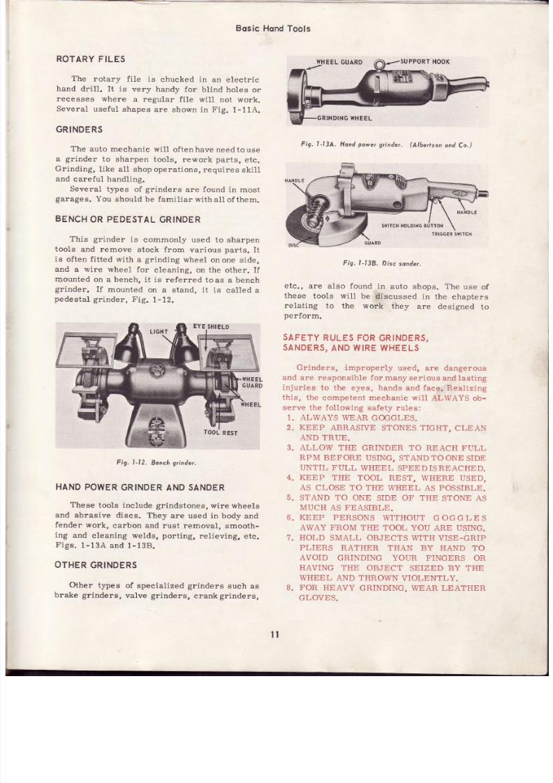
ROTARY
FILES
The
rotary f i le
is
chucked in
an
electr ic
hand
dril1. I t is
very
handy
for
blind holes
or
recesses
where
a regular
f i le
wil l not work.
Several
useful
shapes
are
shown in Fig.
1-11A.
GRINDERS
The
auto mechanic
wi l l
of tenhave
needtouse
a
gr inder
to
sharpen
tools,
rework
parts,
etc.
Grinding,
l ike all
shop operat ions,
requires
skil l
and
careful
handling.
Several
types
of
grinders
are found
in most
garages.
You
should
be famil iarwithal lof
them.
BENCH
OR
PEDESTAL
GRINDER
This grinder
is
commonly
used to
sharpen
tools
and remove
stock from
various
parts.
It
is
often f Í t ted
with
a
grinding
wheel
onone side,
and a wire wheel for cleaning, on the other. I f
rr.rounted
on a beneh,
it is referred
to
as a bench
grinder.
If
mounted
on
a stand, it is
called
a
pedestal
gr inder,
Fig.
1-12.
Fig. l-12.
Bench
grinder.
HAND
POWER
GRINDER
AND
SANDER
These
tools include grindstones,
wire wheels
and
abrasive
discs. They
are used in body
and
fender
work,
carbon
and rust removal,
smooth-
ing and eleaning welds, port ing,
relieving,
etc.
Figs.
1-13A
and
1-138.
OTHER
GRINDERS
Other
t¡pes
of specialized
grinders
such as
brake
grinders,
valve
grinders,
crank
grinders,
Fig. lJ3A.
Hond
power
yinder.
Albertson
ond
Co.)
Fig. l -138. Discsonder.
ete. ,
are also found
in
auto
shops.
The
use
of
these
tools wi l l
be díscussed
in
the
chapters
reLating
to the work
they
are designed
to
perform.
SAFETY
RULES
FOR
GRINDERS,
SANDERS,
ND WIRE
WHEELS
Grinders, improper ly
used,
are dangerous
and
are responsible for
many ser ious
and
last ing
injur ies
to the eyes, hands
and
face. Real iz ing
this, the competent mechanic wi l l ALWAYS ob-
serve the fol lowing
safety rules:
1. ALWAYS
WEAR GOGGLES.
2.
KEEP
ABRAS]VE
STONES
TIGHT,
CLEAN
6
7.
AND TRUE.
ALLOW THE
GRINDER TO REACH FULL
RPM
BEFORE
USING, STAND TOONE
SIDE
UNTIL FULL
WHEEL
SPEEDISREACHED.
KEEP
THE TOOL
REST,
WHERE USED,
AS
CLOSE TO THE
WHEEL
AS
POSSIBLE.
STAND TO ONE
SIDE
OF THE
STONE
AS
MUCH
AS
FEASIBLE.
KEEP PERSONS
WITHOUT
GOGGLES
AWAY FROM THE TOOL YOU ARE USING.
HOLD
SMALL OBJECTS
WITH VISE-GRIP
PLIERS
RATHER THAN
BY HAND TO
AVOID
GRINDING YOUR FINGERS
OR
HAV]NG THE
OBJECT
SEIZED BY THE
WHEEL
AND
THROWN
VIOLENTLY.
FOR
HEAVY
GRINDING,
WEAR
LEATHER
GLOVES.
^
11
RINDING
WHEEL
EYE
SHIELD
B.

7/26/2019 Auto Service and Repair - Martin W. Stockel
http://slidepdf.com/reader/full/auto-service-and-repair-martin-w-stockel 12/224
CLEARANCE
AN
o
t0
11
BE CAREFUL
NEVER
TO
STRIKE
A
GRIND-
ING WHEEL
WHILE
REVOLVING
.
IT MAY
SHATTER
AND
LITERALLY
EXPLODE.
PROTECT
YOUR EYES
BY WEARING
AN
APPROVED-TYPE
FACE SHIELD
OR
GOGGLES.
AVOID GRINDING
IN THE
PRESENCE
OF
EXPLOSIVE
VAPORS
.
GASOLINE,
PAINT
THINNER,
BATTERIES,
ETC.
12.
WHEN
INSTALLING
A NEW STONE
MAKE
CERTAIN
IT
IS DESIGNED
FOR TITE
RP M
OF THE GRINDER.
13. WHENEVER
POSSIBLE,
HAVE
THE GRIND.
ING
WHEEL
GUARD
IN
PLACE TO
MINI-
MI.ZE
THE DANGER
OF
FLYING
PARTS.
14. REMEMBER, GRINDERS
AND
WIRE
WHEELS
CAN
BE DANGEROUS
TOOLS
-
USE
THEM WITH CARE
-
ALWAYS:
DRILLS
The mechanic
has
many uses
for twist
dril ls.
The better
quality dri l ls,
made of
high-speed
steel,
wil l do a
good
ob
of
dril l ing on
most
parts
of
the
car
and can
be readily
ground
without
drawing
their
temper. Carbon
steel
twist
dril ls
are cheaper
but require
frequent
sharpening
an d
lose their
temper
if slightly
overheated.
A set of
f ract ional s ize
dr i l ls
f rom 1/16
to
t lz
¡n.
(29
dr i l ls to
the set) , a
set of
number
dr i t ls
from 1
to 60,
p lus
9/16,5/8
and
3/4
in.
dril ls, wil l handle just about any requirements.
A
typical twist dr i l l
is i l lustratedin
Fig.
1-14.
Fig.
l-14.
Typicol
twist dr i l l
SHARPENING RILLS
Select a new 1 2 ín. dri l l and without start ing
the
grinder,
place
the cutt ing
edge
of the
li p
either on
the side
or on
the
face of the
wheel.
Keep the
shank
lower
than
the
tip. With
a slight
rocking,
pivot ing
motion, eause
the
dril l 1ip
surface
to slide
across
the
wheel.
Always start
at
the
cutt ing
edge and
end at
the
heel.
Keep
trying this
unti l
you
can
go
throughthe
sharpen-
ing motion
keeping
the l ip
in
proper
contact
at
all t imes.
-f-,t
I2
DEG.
I2
DEG.
Fig.
I-15.
Dril l
l ipongles.
A
ondB-Generol
urpose
oint.
Angle
slrown
n
B
is
for cleoronce.)
-Fo¡cost
ironond
oluminum. -
Rubber,
wood, F-Hord,
oughstee/. Nofe
fhot
the
"bock
roke"
or cleoronce
ngles
re he
some
n all excep ' Cleorcnce
ngles
ore
shown
n
block;
ip ongles n colo¡.
Now
select
an
old dr i l l ,
3/B
in. or larger,
start
the
grinder
(goggles
on,
safety
shield
in
place)
and try
sharpening the
dril l .
Remember
to start at
the
eutt ing
edge and
finish at the
heel.
Both
cutt ing
lips should
be the same
length
and
angle.
The
12 deg. angle,
formed
between
the
cutt ing
1ip and
heel,
is
very
important.
Th e
heel must be
lower
in
order
for the dri l l
to
cut.
Fig.
1-15.
Although
dril l l ip angles are
varied
forwork
in dif ferent metals, the angle s shown
in Fig.
1
1 5
wi l l
produce good
all-around eutt ing.
Grind s1ow1y and frequently quench the dril l ,
by dipping it
into
cold
water. Avoidoverheating,
especially
with
the carbon steel
dri l ls.
Use a
simple
dril l
gauge
to
help you
get
the
proper
angles,
Fig.1-16.
-DRILL
GAUGE
-
59 DEG
Fig.
I-16.
l ls ing
o dri l l
gouge.
TÁís
simp/e
gouge
wi l l
check
ongles
ond |ength.
Lip lengfhs
A
ond B
must6e fhe
some.
l2
7/26/2019 Auto Service and Repair - Martin W. Stockel
http://slidepdf.com/reader/full/auto-service-and-repair-martin-w-stockel 13/224
Bqsic Hqnd
Tools
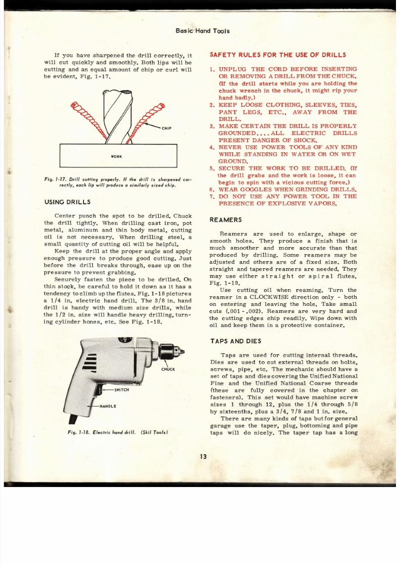
I f you
have
sharpened the dri l l
correct l¡ i t
wil l
cut
quickly
and smoothly.
Both
lips wil l be
cutting and an equal amount
of chip
or curl
will
be evident , Fig.
1-17.
Fig.
l-17. Dri l l cutt ing
properly.
I l the d¡i l l is
slrorpened or-
rectly, each l ip wi l l ptoducea similor ly sized chip.
US¡NG DRILLS
Center
punch
the spot to be dril led. Chuck
the drill
tightly. When drilling
cast
iron,
pot
metal,
aluminum
and thin body metal,
cutt ing
oil is not neeessary.
When
dril l ing
steel, a
small
quantity
of
cutting oil
will
be
helpful.
Keep the drill
at the
proper
angle and apply
enough
pressure
to
produee good
cutting.
Just
before the
dril l breaks
through, ease up on the
pressure
to
prevent
grabbing.
Securely fasten the piece to be dril led. On
thin
stock,
be
careful to hold it down as it has a
tendency
to
cl imb up the
flutes. Fig.
1- 18
pictures
a tJ4 in . e leetr ic hand
dr i l l .
The
3/8 in . hand
dril l is
handy with medium
size dril ls, while
the
tl2 in.
size
will handle
heavy dril l ing,turn-
ing
cyl inder
hones,
etc.
See
Fig.
1-18.
SAFETY
RULES FOR THE USE
OF
DRILLS
1. UNPLUG
THE
CORD
BEFORE
INSERTING
OR
REMOVING
A DRILL
FROM THE CHUCK.
(If
the drill starts
while
you
are
holding the
chuck wrench in the chuck,
it might
rip
your
hand badly.)
2.
KEEP LOOSE
CLOTHING, SLEEVES,
TIES,
PANT LEGS, ETC., AWAY FROM THE
DRILL.
3.
MAKE CERTAIN
THE DRILL
IS
PROPERLY
GROUNDED... .
ALL
ELECTRIC DRILLS
PRESENT DANGER OF
SHOCK.
4. NEVER
USE
POWÉR TOOLS OF ANY
KIND
WHILE
STANDING
IN WATER
OR ON
WET
GROI ND.
5.
SECI]RE
THE
WORK
TO BE DRILLED.
(I f
the dril l
grabs
and
the work is loose,
it
can
begin
to
spin
with
a vieious cutting
force.)
6. WEAR GOGGLES WHEN GRINDING DRILLS.
7. DO NOT USE ANY
POWER TOOL IN
THE
PRESENCE
OF EXPLOSIVE
VAPORS.
REAMERS
Reamers
are used to enlarge, shape or
smooth
holes. They
produce
a finish that is
much
smoother
and
more
accurate than
that
produeed
by dril l ing.
Some reamers
may
be
adjusted and
others are of a
fixed
size.
Both
straight
and tapered reamers are needed.
They
may
use e i ther stra ight or sp i ra l
f lu tes,
F ig.1-19.
Use
cutting
oil
when
reaming. Turn
the
reamer in a CLOCKWISE direction only
-
both
on
entering and
leaving the hole.
Take
small
cuts
( .001
.002).
Reamers
are very
hard and
the
cutting edges chip
readily. Wipe down
with
oil
and
keep them in a
protective
container.
TAPS
AND
DIES
Taps
are used
for
cutting
internal
threads.
Dies
are used to cut external threads on
bolts,
screws,
pipe,
etc.
The
mechanic
should
have a
set of taps and diescoveringthe UnifiedNational
Fine
and the
Unified National Coarse threads
(these
are
fully
covered
in the
chapter
on
fasteners).
This
set would have machine
screw
sizes 1 through 12,
plus
the ll4 through
5/ 8
by s ixteenths,
p lus
a 314,
?/8
and 1
in. s ize.
There
are
many kinds
of
taps butforgeneral
garage
use
the taper,
plug,
bottoming
and
pipe
taps
will do nicely.
The
taper tap
has a long
. .k;
;:.i
t;;*
Fig. I-18. Electr ic hond dri l l .
(Sktl
Tools, l
t3

7/26/2019 Auto Service and Repair - Martin W. Stockel
http://slidepdf.com/reader/full/auto-service-and-repair-martin-w-stockel 14/224
Auto
Serviceond
Repoir
The
pipe
tap
is tapered over
the
full length
(about
314
in.
per ft.) and
is used
to tap
holes
for
pipe fittings.
Taper,
plug,
bottoming
and
machine screw
taps
are
il lustrated
in
Fig.
1-20.
TAPPING
First,
determine
exactly
the
number
of
threads
per
inch and
the
diameter of
the screw
that
will enter
the
hole.
Referring to a
tap
drill
s ize chart
(F lg.
1-21),
select
the
proper tap
size
dril l .
\
OR K
f-E
:
ct
- -l
TAP DRIIJÍJ
SIZES
R€oñh.¡dd lor
¡MENICAN NTTION¡L
SCRTW TTIREID
PITICHES
Fig. t-19. Reomers.
A-Enlorged
seclion
sfiowing
rcamer
looth
consfrucfion.
B-Reomer
tooth
removing
stock.
C-Nonodiustoble,
spirol
(lute
reome¡.
D-Nonodiustable,
straight
llute
¡eamer.
E-
Ád¡ustoble stroight
reomer.
,
is
opened
ond closed
by
removing
the
odiusting
nuts.
chamfer
(about
10 threads)
that
allows
it
to
start
easily.
It
cannot,
however,
be usedinblind
holes
where the
thread
must
run almost
to
the
bottom.
The
plug
tap has
a shorter
chamfer
(about
5
threads) and
with
care,
can
be
started
successfully.
It is useful
for open
holes
and
for
blind
holes.
The bottoming
tap
has a
short
chamfer
(about
1
thread)
and
is used
in
blind
holes to finish the thread to the bottom of the
hole. The
plug
tap
shoutd
be
used
first and
when
it strikes
bottom,
the
bottoming
tap should
be
.used.
i--+re
TAPER
PLUG
Fig.
l-21
Top
&ill size chart.
(South
Bend
Loth)
For example,
say that
you
desire
a threaded
hole
for
a
7
116
in. screw
with
20 threads
pe r
inch. Looking at the ehart, you will find that a
7lt6
in., 20 threads
per
inch,
is a
Unified
National
Fine
size. Going
directly
across
from
the
7116
in.
UNF,
you
will
notice a column
marked
"Tap
Dril l
Size."
In this case,
the
tap
dri l l
s ize
for
a
?/16 in .
x 20 isa25l64
in. dr i l l .
What
would be
the
correct
tap size
drill
to
use
for a serew
3/8
in. in
diameter
with 16
MACHINE
CREW
Fig.
l-20.
Typicol
ops.
Amount
Í chomler
o¡ieswith eocñ
ype.
COARSE
STÁNDARD
THREID
(N.
C.)
SPECIIL
THRETD
N.
S.)
:it
I
l -r /8
r-r
14
2
4
5
I
l0
t2
r1 4
s/r6
318
7116
r12
9/16
s/8
314
71 8
56
,18
40
,¡O
32
32
24
24
20
¡8
l6
t4
¡3
ll
l0
9
I
a
7
.66
.099
.l l2
.125
.138
.164
.190
.216
.zfi
.31?5
.3?5
.{3?5
.500
.5623
.625
.?50
.875
l. @
1.t25
t.250
5/16
U
27lA
3t/6{
r7l&
2r
132
4916Á
71 8
63/6{
r-7t64
s
50
a7
43
38
36
a
I
t6
7
r
0.üm
0.0?8 t
0.(E90
0.1013
0.1(b5
0.t360
0.t495
0.17?0
0.2010
0.2570
0.3125
0.3680
0.{2r9
0.48€
0.33r2
0.656¿
0.?636
0.8?5
0.9843
Ll0s3
{ l
{l
el
el
t0
l
12
l
l{
t{
/ 16
3le
r18
ste
sl9
3/r6
3/r6
713¿
719
rl l
rl l
r la
5/16
s1r6
5/r6
3/8
3/8
?/16
7lr8t1 2
r1 2
r12
9/16
3/8
sl8
r¡/16
r t /16
3l r
31 4
7le
7le
71 8
I
I
I
36
36
ao
30
&
m
A
64
t8
|0
32
38
u
3[¡
2l
9,
u
27
3¿l
6
n
3a
m
2t
2l
?:It2
2a
27
27
t2
27
u
t6
t2
n
12
t8
n
tz
n
. t tm
.1t20
.t380
.teo
.tgm
.2td)
.Hin
.zan
.0623
.09t¡8
.12 n
.lsgt
.tsdt
.18?5
.18?3
.2r88
.2188
.2to
.29
.250
.3123
.3t25
.3125
.3?5
.3?3
.43?S
.$75
.s00
.s00
.3oo
.56¿5
.625
.62tt
.68?3
.68?5
.nn
.750
.8?5
.8?3
.875
¡-000
l.(m
{5
aa
3{
n
a
l3
t0
7
3/6r
a9
38
l/ 8
30
I
2
t6
t2
{
3
R
x
Y nlEa
?€rc1
r3l9
ru9
35/64
rs13¿
r9l3z
s/8
43l6¡
alu
3r/64
53/8{
2713¿
39/64
3rlu
713¿
17lil
913¿
2rls
,t
0.@0
0.@
0.l l 0
0.ta{E
qr',o
0.18c)
0.t935
0.2010
0.0a6¡
0.üno
0.10t3
0.t230
0.t285
0.t470
0.t$r0
0.ri?o
0.1890
0.2G0
0.2¡30
0.2t8?
0.2656
o.zno
o.m2
0.3281
0.9$0
0.3970
0.(x0
0.{2t9
0.¡1531
0.{68:t
0.sitl2
0.3469
0.$:¡7
0.3git7
0.6350
0.6?19
0.?18?
0.7969
0.828¡
0.8¡13?
0.92t9
0.9687
FINE STANDARD
THRETT.D
(N.
F.)
1ir:lii'
0
I
2
{
ó
l0
t2
r1 4
5/r6
3/8
7116
r12
9/16
s/8
31 4
71 8
r-r/8
l-v4
80
72
6,1
s6
¡t8
{{
40
36
32
I
I
2{
24
20
20
l8
l8
l6
l{
l{
l2
t2
.060
J?3
.086
.099
.l
l2
.l s
.16{
.190
.216
.250
.3125
.3?S
.4:l?5
.sm
.56¿5
.?50
.875
1.000
l.125
¡.2S0
st
50
4S
12
37
3i¡
A
2l
ta
3
¡
o
2s161
?9164
0.8062
0.5687
rr/16
0.80m
o.gna
r-3/64
l-l ¡/64
0.0t¡95
0.07(x)
0.0820
0.0935
0.10,|()
0.1130
0.t360
0.1590
0.¡820
0.2130
o.2720
0.3it20
0.3906
0.4cll
0.506?
0.5687
0.68?5
0.8@o
o.9271
¡.0468
t.1718
BOTTOMING
l4

7/26/2019 Auto Service and Repair - Martin W. Stockel
http://slidepdf.com/reader/full/auto-service-and-repair-martin-w-stockel 15/224
Fig. 1-22.
Assorted ops ond dies.
(Snop-On
ools)
threads
per
inch? Checking the chart,
you
will
f ind i t to
be 5/16
in,
Drill
the
hole with
a tap size drill
(holes
over I
14
in.
should be dril led
in at least two
operations
-
start
with
a
small
pilot
dril labout
an 1/B
in. in
diameter, and
work up to the tap
dril l).
Using
a suitable tap
wreneh,
carefully
start
the tap. Cutting oil
wilL
help
when
tapping steel.
After
running the tap in
for
one or two turns,
back the tap up about
one-half
turn to break the
chip.
Repeat
this
proeess
until
fully tapped.
Re-
member that taps
are very
brittle. Donot strain
them and be sure to keep
the
hole
from
clogging
with
chips.
The
die
is used much like the tap.
After
selecting a die of the
correct
size,
place
it in
a die
stock
(handle),
apply
cutting
oil
to
the
bolt
and start the die. Use the
same
turn and back
method used
for
tapping.
Dies
are often adjustable
so the thread
fit
can
be
ehanged.
Adjust so that the nut
will turn
on smoothly with finger pressure. Keeptaps an d
dies
clean, oiled,
and in
a
box.
There
are
many
special
purpose
taps and
Fig. l-23. Hocksow
lrome.
(Owottono
Tool
(orp.)
dies,
Fig.
1-22 shows
a
number of
them: A
-.
external
rethreading set,
B
-
internal thread
restorer , C-thread
restorer ,
D-axle
re-
threader
which
is
opened
up and
placed
around
the
good
threads and
backed off,
E
and
F
-
nut
dies that can
be operated
with
aboxend
wrench,
G and
H
-
spark
plug
hole thread
restorers
-
very
handy
for
removing
rust and carbon,
J
-
combination
tap
and die set
for
tube
fittings,
K
-
tap
and die set
with taphandle
anddie stock.
HACKSAWS
A hacksaw
is used to cut
tubing,
bolts, etc.
The mechanic should
have blades with 18,24,
and32teethper
inch.
The
1B-tooth
blade
is used
for
cutting
thick
metal, the
24-tooth
formedium
thickness,
and the
32-tooth
blade
for
thin
sheet
metal and tubing.
The blades should
be of
high
quality
steel
as they
will
cut
faster and
longer
than low
quality
blades.
Fig. l-23,
i l lustrates a
typicat
hacksaw
frame.
For
very
thick
work,
use a
14-tooth
blade.
OTHER
HACKSAWS
A special
hacksaw, termed
a
t' iab
saw,rr
wil l
facilitate
eutting
in tight
quarters.
A
hole saw,
driven
with an electric
drill,
is handy
for
cut-
t ing
large
holes in sheet
metal. See
Figs.
1-24
and 1-244.
Fig. l-24A.
Hole sow.
Cutters
oÍ
vo¡ious
sizes ore
ovoiloble.
(Snop-On
ools)
TENSION
ADJUSTE
Fig.
l-24. Jab sow, o handy
tool in right
qeoilerc.

7/26/2019 Auto Service and Repair - Martin W. Stockel
http://slidepdf.com/reader/full/auto-service-and-repair-martin-w-stockel 16/224
Fig. l -25.
Typicol
bencfiv ise.
VISE
A vise
suitable for automotive work is
p ictured
in
Fig.
1-25.
Keep
the
vise c lean, use
copper jaw eovers for work thatmaybemarred,
oil the working
parts
and avoid
hammering
on
the
handle
or on other
surfaees.
CLEANING
TOOLS
A number
of useful
cleaning tools are i l lus-
t rated
in
Fig.
1-26. Having
a
select ion
speeds
up
cleaning
work. The
wire
wheel
and
power
cleaning brushes
are mounted in
an eleetric
dril l . USE
GOGGLES
WHEN OPERATING
TH E
WIRE
WHEEL
AND ALSO
WHEN
CLEANING
WITH
CAUSTIC
(WILL
BURN
SKIN
AND EYES)
SOLUTIONS.I
Fig. l -26.
Cleaning
¡ools.
l -Hol low
corbon brush.
2-l l i ¡e b¡ush.
3-Wire
wáeel.
4-Flexible
scroper.
S-Twisted strond wire b¡ush.
6-Bristle
head. 7-Rigid
scraper.
8-Cor6on
b¡ush. 9-B¡is¡le 6rush
ond
holder.
l0-A¡bo¡ for wi¡e
wheel . I l -Cieoning
brush wi th ny-
lon
6ríst/es.
l2-Hond wire
scrofcfi brusñ,
SCREWDRIVERS
The mechanie
should own several
different
sizes
of screwdrivers
of the
standard,
Reed
&
Prince,
Phil l ips
and
Clutch
types;
Fig.
1-2?.
The
offset
screwdriver
shown in Fig.
1-27,
is useful in tight quarters where evenattstubbytt
cannot
be
used.
Fig.
l-27,
Screwdriver
fypes.
Wren
usíng
screwdrivers,
selecf
the r ight
type ond
size,
A
good
ossortmenf s
essentiol .
HANDLING
SCREWDRIVERS
Use
a screwdriver in keeping
with the
job.
Avoid
prying
with
or
hammering
on the
screw-
driver.
(Some
verylarge
screwdrivers are made
so that minor
prying
and hammering will
not
harm them.)
When
grinding
a new
tip on the standard tip
screwdriver, maintain
the original taper. Do
not
grind to a sharp point or to a
steep taper as the
tip will
either twist
off or
climb out of the slot.
Avoid
overheating.
See
Fig.
1-28.
CAUTIONj
WHEN HOLDING
SMALL
I]NITS
IN THE HAND,
DO NOT
SHOVE
DOWN ON THE
SCREWDRIVER
HANDLE
AS IT MAY
SLIP AND
Fig.
l-28.
Correcf sfiorpening
is importon¡.
A
and
B-F¡ont ond
side
view
of co¡¡ect
sfiope.
C-Too sfeep ond sñorp.
D-Correct
toper ond
size.
E-Steep an gle will
"climb our" of
screw slot.
F.
'
Screwd¡iver
ground
too thin;
it will twist
o|l.
u
-
\t¡l
CLUTCH
/ñ
l\lV
t:
-7
REED
AN D
PRINCE
0
t
PHILLIPS
F
ü
E
I
D
I
c
I
t6

7/26/2019 Auto Service and Repair - Martin W. Stockel
http://slidepdf.com/reader/full/auto-service-and-repair-martin-w-stockel 17/224
PIERCE
YOUR
HAND.
IF
WORKING
ON
ELEC.
TRICAL
EQUIPMENT,
SHUT
OFF THE
CUR-
RENT,
USE
AN INSULATED
(FULL
LENGTH)
SCREWDRIVER
AND KEEP
YOUR
HANDS FREE
OF
ANY
WIRES WHERE
IT IS IMPOSSIBLE
TO
SHUT OFF
THE
CURRENT.
IF.YOU
MUST
WORK
AWAY FROM
AN OPEN
SWITCIT, TAG IT
SO
THAT SOMEONE WILL NOT ACCiDENTALLY
TURN
IT ONJ
PLIERS
Pliers
are
used
for
cutting
wire, holding
parts,
crimping
connections, bending
cotter
pins,
etc.
The
combination
slip
joint,
vise-grip,
adjustable
rib
joint,
battery, pump,
ignit ion,
Long
nose, needle
nose,
diagonal
and side
cutter
pliers
are
most
often used. Other,
more
specialized
pliers
such
as
the
snap ring,
hose-clamp,brake
spring, wil l
be
covered
in
later
chapters. Avoid
cutting hardened objects and never use pliers
to turn
nuts,
bolts
or tubing fitt ings,
Fig.
1-29.
q.
Fig.
l -29. Uselul
pl iers.
l -Needle
nose.
2-Chain nose.
3-Elec-
tr ic ion. 4-Diogonol . 5-Rí6 ioint. 6-lgni i ion. 7-Conbinotion sl ip
joinr.
8- Vise-grip
or
pl ier
wrench.
(Utico
ond Proto
fools)
BOX
ENDWRENCHES
Box
end wrenches
are available with
12-point
or 6-point
openings.
The
12-point allows a short-
Fig.
l -30,
8ox
end w¡encñes.
A-Double
oflset.
B-1S-deo. ffser.
er
swing while
the 6-point provides
superior
holding power.
One
design
uses a double
offset
to
give
more handle
clearance while
another
uses
the
popular
15-deg.
offset.
Differentlengths
plus
a
complete range
of
opening
sizes
ar e
needed, F lgs.
1-30
and
1-31.
Fig. l -31.
Box end w¡ench.
sef,
short length
ype.
Slrown is o lS-deg.
ofl-
(J.
H.
Wi l l ions)
Fig.
l-32.
Combina¡ion lore nut
and
open
end wrench.
FLARENUTWRENCH
The
flare
nut wrench
is
quite
similar to the
box
end wrench
but
has a section
cut out
so
that
it
may
be
slipped around tubing
and
dropped over
the
tubing
nut. This
wrench
has
either 6-point
or
12-point
opening.
The
flare
nut wrenchis
amust
for
carburetor,
vacuum,
brakes,
etc., f it t ings,
F ig.1-32.
RATCHET
BOX END
This
is a ratcheting
tool using
a
box end
de-
sign.
It
is fast
to use
andhas
many
applications,
Fig.
1.-33.
OPEN
END
WRENCH
The
open end úrench
grasps
the nut on only
two
flats. Unless
it f its well,
it is
apt to slip
and
round
off
the
nut.
There
are many
places,
FLARE
NUT IEAD
TUBING
SLIPS
THROUGH

7/26/2019 Auto Service and Repair - Martin W. Stockel
http://slidepdf.com/reader/full/auto-service-and-repair-martin-w-stockel 18/224

7/26/2019 Auto Service and Repair - Martin W. Stockel
http://slidepdf.com/reader/full/auto-service-and-repair-martin-w-stockel 19/224
)OCKET
HANDLES
Several
d i f ferent
dr ive
handlesareused.
The
.::ed
handle
is
used
whenever
possible
as
i t
-=:,
be turned
raPidlY,
Fig. 1-38.
Flex
handles
of
different
lengthprovide
heavy
:
- : : , rng
leverage
and
maybe
used
at
many
angles,
.
: .
1-39.
The
sliding
T-handle
has
some
applicatíons
=, . . ishould
be
inc luded
in a socket
set,
Fig. 1-40
Spinner
handles
are
used
much
as
screw-
-:
.,-ers
and
wil l accept
all
the
socket
attach-
::- - :nts ,
Fig, 1-41.
The ratchet
handle
allows
both
heavyturning
:: :ce
and
speed.
The
fastener
can
be
turned
in
_: out
by
fl icking
a
lever
on
the
ratchet.
The
ra:chet
is a lso
useful
where
a l imited
swing
is
::cessary,
Fig. l -42.
\ ratcheting
adapter
can
be
used
with
a
flex
:.=:dle,
T-handle,
etc .,
thus
making
them
quite
. : rsat l Ie, .r19, r -+J.
The
universal
joint
will
permit
driving
at
:r iferent angles
with
the various
sockethandles,
r -g.
L-44.
Sockets
of
one
particular
drive
size
can
be
:rned
with
the
handles
from
another
by using
an adapter ,
Fig.
1-45.
CTHER
SOCKET
ATTACHMENTS
Screwdriver,
drag
link
and
crowfoot
socket
=:tachments
are
a
few
of
the
many
offered,
|
-4h
Fiq.
l
-40.
Socket
sl id inq
T-hondle
Fig . 1 -41 Sockel sPínner hondle
Fig.
l -43. Socket
otchefing
odopter
(J
H
l l í l l ions)
Fig.
l -44. Socket
universo/
oinf.
Fig,
I
-45.
Sockef
odoPfer
l -46, O¡her
sockel
olfochments.
l-Screwdtiver
2-Drog
l ink
3-Crowloof.
(EonneY
Tools/
Fis.
Fiq.
l -42. Sockef
rofchef
hondle.
(Owottono
Tool
CorP )
19
Fig.
1-46A.
Sockef
exlension
bors
(J
H
Yl i l l ions)
7/26/2019 Auto Service and Repair - Martin W. Stockel
http://slidepdf.com/reader/full/auto-service-and-repair-martin-w-stockel 20/224
1i
rli
Auto
Service
ond
Repoir
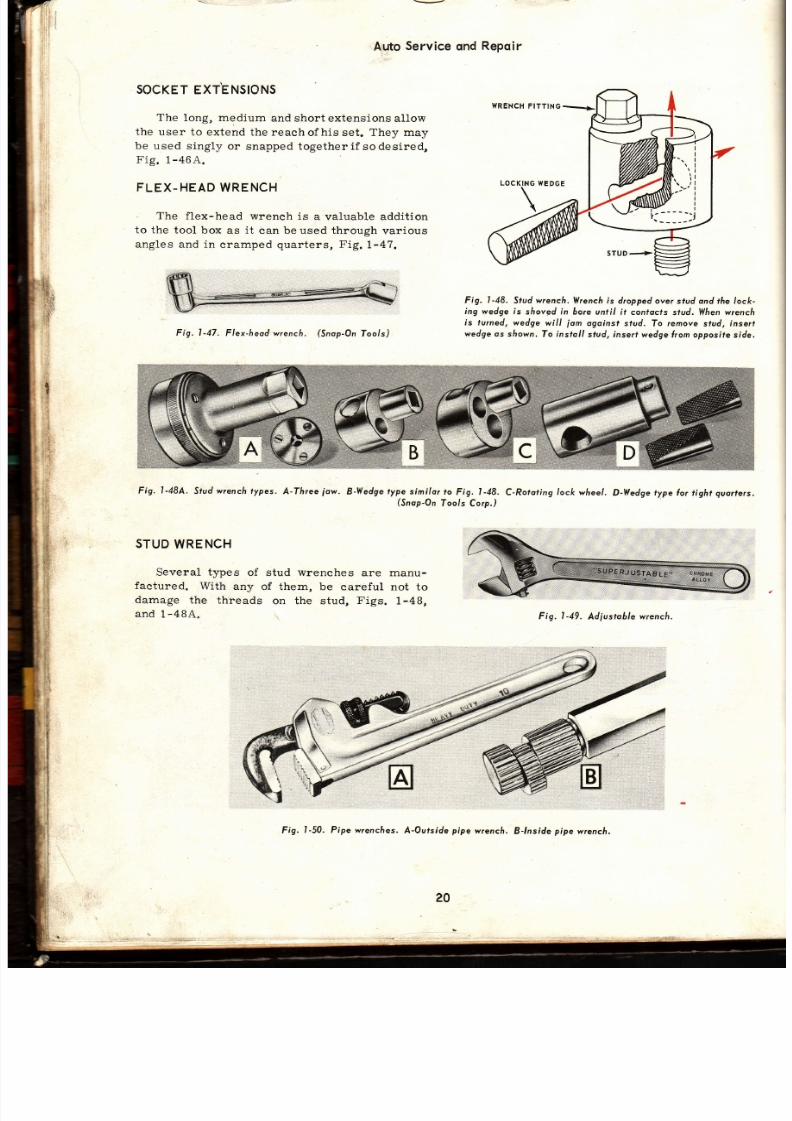
SOCKET
XT.ENSIONS
The
long, medium
and
short extensions allow
the
user to extend the reach
ofhis set. They may
be used s ingly
or
snapped together i fsodesired,
Fio 1-46A
FLEX-HEADWRENCH
The
flex-head wrench
is
a valuable addition
to
the tool box
as
it
can be used through
various
angles and in
cramped
quarters, Fig.1-47.
Fig.
l -47.
Flex-heodwrench.
(Snop-On
ools)
Fig, l-48.
Stud
wrencfi.
l l ¡enc/r
is
droppedover
stud
ond
the lock-
ing wedge is
slroved
in
bore uniil
i f confocfs
s¡ud. llhen
wrench
is turned, wedge
wi l l
¡om
ogoinst
stud. To
remove
stud,
insert
wedge os
slrown.
fo
instoll
stud, insert
wedge rom opposife
side.
Fig-
l -48A.
Stud
w¡enc/r
ypes.
A-Three
ow.
B-Wedge
ype
simi lor
o
Fig. 1-48.
C-Rororing
ock
wheel .
D-l ledge
ype lor
t ight
quo rers.
(Snop-On
oo/s
Corp.)
STUD
WRENCH
Several types
of stud
wrenches
are manu-
factured.
With
any
of them, be
careful not to
damage
the
threads
on the stud,
Figs.
1-48,
and
1-484.
Fig. l -49.
Adjustoblewrencfi .
F ig.
I-50. Pipe wrenches,
A-Ourside
pipe
wrench.
8-fnside
pipe
wrench.
.f
1r
20

7/26/2019 Auto Service and Repair - Martin W. Stockel
http://slidepdf.com/reader/full/auto-service-and-repair-martin-w-stockel 21/224
Bqsic Hqnd
Tools
' 'CRESCENT' '
R ADJUSTABLE
WRENCH
The
adjustable
wrench
is
a
useful toolinthat
its
size may
be readily
adapted to that of the
fastener.
However, it is
prone
to loosening and
slipping.
When
other
wrenches
are available
-
use
them,
Fig.
1-49.
PIPE
WRENCHES
The
pipe
wrench
is
used to
grasp
ir regular
or round
surfaces. It
provides great
gripping
power.
Both
inside
and
outside
pipe
wrenches
should be available, Fig.
1-50.
ALLEN
ANDFLUTED
WRENCHES
These
wrenches
are used
to
turn
setscrews,
cap
screws,
etc. , Fig.
1-51.
Fig. l -51. AIlen ond
luted wrenches.
BEWAREJ
WHEN
USING
ANY WRENCH, MAKE
CER-
TAiN
THE
WRENCH
IS THE
CORRECT
SIZE
AND IS SECURELY ENGAGED, PULL, DO NOT
PUSH.
IF
PUSHING
IS
ABSOLUTELY NECES.
SARY,
OPEN
THE HAND
AND PUSH
WITHTHE
PALM.
BE
CAREFUL, IF
A WRENCH
SLIPS,
YOU
CAN GET
A
SERIOUS CUT:
Fig. l -52.
Prohing tools.
A-Mechonicol
inger
pickup.
B-Tele-
scoping
mognet.
C-Telescoping
mirror.
PROBING
OOLS
Mechanical
f ingers,
extension
magnets
an d
mirror
devices
help
the mechanic
to
retr ieve
parts
and to
see in
bl ind
areas,
Fig.
1-52.
POWER
OR
IMPACT
WRENCHES
An
electr ic ,
or
pneumatic
(ai
r ) impact
wreneh,
used in
conjunct ionwith
sockets, speeds
up the
job
a
significant
amount. Most
shops
are
now using
them,
Fig.
1-53.
Fig. l -53.
Electr ic impoct wrench.
(Albertson
Co.)
OTHERS
O FOLLOW
As mentioned earlier, many other more
speeial ized
tools wi l l be
discussed in
th is text.
When,
in your
reading, you
come across one,
pay
particular
attention to
the name
and
how it
is used. Many
jobs
in
the shop
can
be made
either
t ime
consuming and difficult
or
fast
and
easy, depending
on
an intell igent
selection
of
tools . REMEMBER:
PROPER
TOOL
SELEC-
TION
ANDUSEISVERYIMPORTANT
.
LEARN
ALL
YOU
CAN
ABOUT
THEMJ
SUGGESTED
CTIVITIES
Wrrte
to a
number
of tool
manufacturers
an d
ask
for
a
copy
of their tool
catalog,
and any
informative brochure
s
they may offer
concerning
their
products. You
may
find
their names and
addresses by looking
in
automotive trade
prye-rs.
After
¡rou
have
received your material,
btudy
it carefully.
Learn the names
and suggésted
uses of as
rnany
as
you
ean.
Flick
through
the
7/26/2019 Auto Service and Repair - Martin W. Stockel
http://slidepdf.com/reader/full/auto-service-and-repair-martin-w-stockel 22/224
'#
%
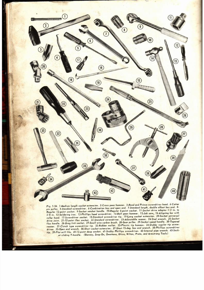
Fig,
1-54.
l -Mediun
lengi l r
socket
extension.
2-Cross
peenhommer' .3 'Reed
nd,Prince
c¡ewdriver
heod'
4 'co¡¡e¡
pin
pul ler.S-stondord
r . i r ] .r .
A-Combinorion
ox
ond
open
end.
7-srondord-length,
ouble
offset
box.end'
8-
Regulor
12-point
o k.r.
f- io.k t
rctch*
hondle.
1}-Reguior
6-point
socket'
lJ 'Socke¡
d¡ive
odoptet
1/2
in '
to
3/g
¡n. l2-Sotdering
ron.
l3-phi l t ips
heod
screwdri r.r . i4-Botl 'peen
hornmer.
5-Job
sown
l6'Al igning
bo¡
wi¡h
rol ler
heod,
I7-Screwdriver.ocker, '
8-srondord
screwdriver
t ip.
l9-Long
sockel
exfension.
20'socker
unive¡sol
driue
ioínt.
21-12-point
lex
socker.
22-S¡ondord
crewdriver.
23-Acliuslobte
reomer'
24'S¡ud
w¡ench'
25-Socker
(lex
hondle.
26-Drcg
ink
socket.
27'Smott
wire
carbon
b'ush'
28'G a'
puller'
29'sockef
speed
hondle'
30-Topered
reome¡.
31-Clutch
type
screwdriver
típ.
32-Rubber
mollet'
33'Plostic
tip
homme¡'
34-Srubhy
e.gulor
ip screw'
driver.
35-Open
nd
w¡ench.
36-Short
ocket
extension'
37'Short
5-de9'
6ox end
wrench'
38-Ptr i l l íps
screwdriver
t ip. 39-Ftot
nít l
l i le.
¿O-l i - i .¡^¡
de p
orkut.
^4t-Sfu66y
Ph¡tt¡Ps
c¡ewdriver '
42' lnternol
pipe
wrencfi '
43-Sock'
etsl id ingT-t,o,¿t..(Bo,,.y,Snop-on,owol fono,|Jt ico,Yl i l ton,Proto,andArmstrongTools)
@

7/26/2019 Auto Service and Repair - Martin W. Stockel
http://slidepdf.com/reader/full/auto-service-and-repair-martin-w-stockel 23/224
.r-q
i
ii
u
1i
Fig.
1-55
44-Point Íile.
Ai-Flex
socket. 46-Rotcfiet
6ox end.
47-Hose
clomp
plier.
Ai-Ratchet open
end. 49-Ccii-
6on
scroper.
Sl Linemon
plier.
51-Adiustoble wrench.
S2-Hacksow ro^e,
ii-F.ele¡ gouge,
S¿-Cot¿
ñisel.
55-
I
/4
in.
elec¡ric drill.
56-Torque w¡encá.
57-Pipe
die.
58-Rtb
ioint
plier.
59-Center
puncfr-.
60-Needle
nose
p/ier.
6 l-Cleaning
brush. 62-Stip
io int
pl ier.
63-CrowÍoot
otlochment,
64-Pipe
wrench. 65-Diogonot
pl ier.
66-OÍlset
screwd¡íver.
67-Allen
w¡encfi.
68-Broke
spring
plier.
69-6-point óox
end.
7l-Choin
nose
p/ier.
Tl
-Storting
punch.
72 Clu¡ch
tip
screwdriver.
73-12-point
ubing wrench.
74-Yise
yip pl ier.7S-Battery
plier.
76-Twis,
d¡¡1. 7 l-C
clonp. 78 Drih
punch.
79-Cylinder
heod
wrench,
80-Rin9 compressor.
8
-S/ide
hommerpuller.
82-5[eer
neto/
sn
ps .
(Bonney,Snop.On,
Owoltono,
Utica,
Vli l ton,
Proto,
Armstrong,
Vli l l ions, Tho¡
ond
gurtevont
foo/s)
¡ ,
I
1.
: i
23
7/26/2019 Auto Service and Repair - Martin W. Stockel
http://slidepdf.com/reader/full/auto-service-and-repair-martin-w-stockel 24/224
Auto Seryice
ond
Repoir
1.
2
3.
4.
5.
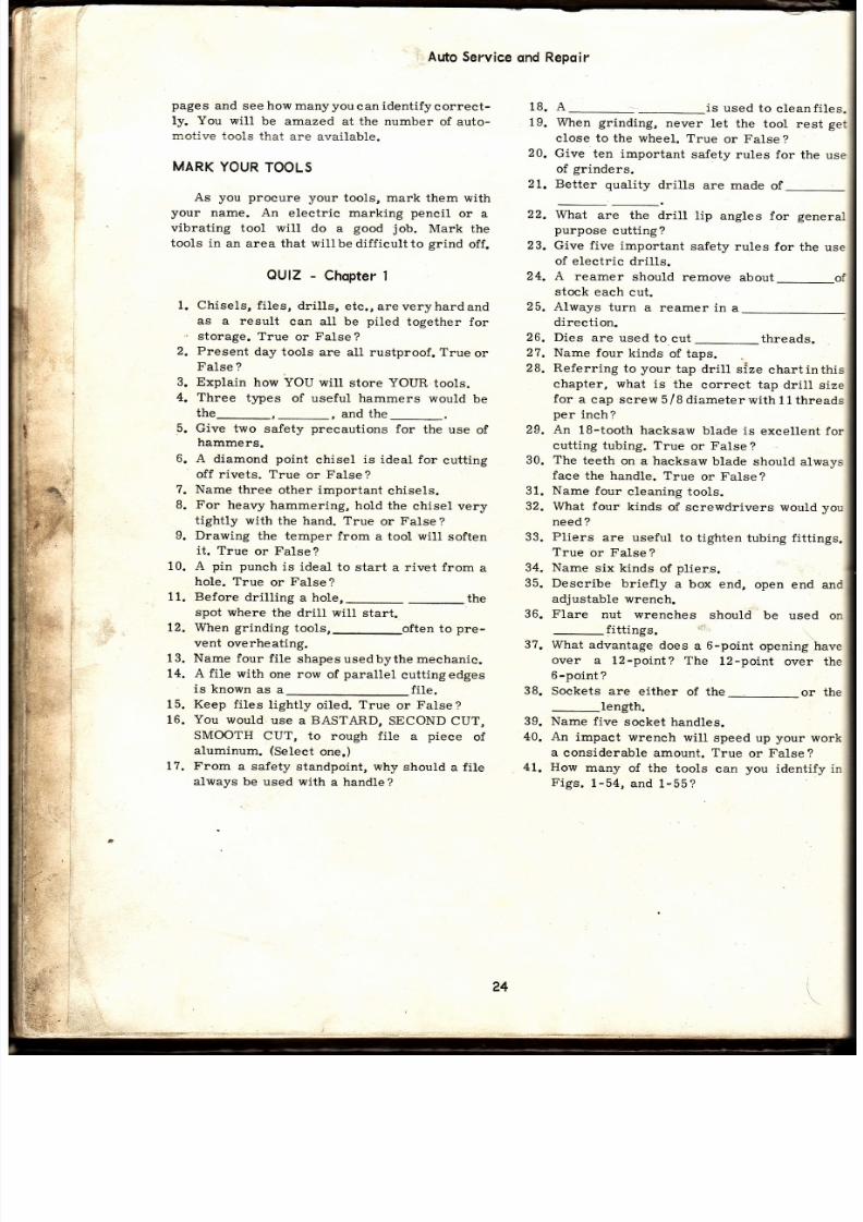
pages
and
see
how
manyyou
can
identifycorrect-
ly. You will
be
amazed at the number
of
auto-
motive
tools
that
are available.
MARK
YOUR
OOLS
As you procure your tools, mark them with
your
name.
An electric marking pencil
or
a
vibrating
tool wil l
do a
good
job.
Mark
th e
tools in
an area that wil lbediff icultto grind
off.
OUIZ
-
Chopter
Chisels,
f i les,
dr i l ls ,
etc. , areveryhardand
as a result
can all be
piled
together for
storage. True
or
False?
Present
day
tools
are all rustproof. True
or
False
?
Explain
how YOU
will
store
YOUR
tools.
Three
types
of useful hammers
would
be
the_,_,
and the_.
Give
two safety
preeautions
for
the use
of
hammers.
6.
A
diamond
point
chisel
is
ideal for
cutting
off
rivets. True
or False?
?. Name
three
other important
chisels.
8. For
heavy
hammering,
hold
the
chisel very
tightly
with
the hand. True
or
False
?
9. Drawing
the
temper from
a tool
wilt
soften
it.
True
or
False?
10. A
pin
puneh
is ideal
to
start a rivet from
a
hole.
True
or
False?
11. Before
dril l ing
a
hoIe,_
_the
spot where the dril l wil l start.
12. When
grinding
tools,_often
to
pre-
vent
overheating.
13. Name
four
f i le
shapesusedbythemechanic.
14. A fil.e
with
one row
of
parallel
cuttingedges
is known
as a
fi le.
15. Keep fi les
lightly
oiled.
True
or
False?
16.
You
would
use
a
BASTARD,
SECOND CUT,
SMOOTH
CUT, to
rough
file
a
piece
of
alur¡inum.
Select
one.)
17.
From
a safety
standpoint, why
should
a fi le
always
be used with
a handle
?
18. A
-_-is
used to
cleanfiles.
19. When grinding,
never
let the
tool rest get
close to the wheel.
True
or False?
20.
Give
ten important
safety
rules for
the
us e
of
grinders.
21. Better
quality
dril ls
are made
of
_
22.
What
are the
drill
iip angles for general
purpose
cuttingr
23. Give
five important
safety
rules
for
the
use
of electric
dril ls.
24. A
reamer
should remove
about_of
stock
each
cut.
25.
Always
turn
a reamer
in
a. -
direction.
26. Dies
are
used
to
cut
_threads.
27. Name
four
kinds
of taps.
28. Referring
to
your
tap
dril l size
chartinthis
ehapter,
what
is
the
correct
tap
dril l
size
for
a cap screw
5/B
diameterwi th
l l threads
per
inch?
29.
An
1B-tooth hacksaw
blade is
excellent for
cutting
tubing. True
or
False?
30. The
teeth
on a hacksaw
blade
should
alwavs
face
the handle.
True
or
False?
31.
Name
four
cleaning
tools.
32. What four
kinds
of screwdrivers
would
vou
need ?
33.
Pliers
are useful
to
tighten tubing fitt ings.
True
or
False ?
34.
Name
six
kinds
of
plier:s.
35. Describe
briefly
a box
end,
open end
an d
adjustable
wrench.
36. Flare nut wrenches should be used on
_
fittings.
,j
37.
What advantage
does
a
6-point
opening have
over
a l2-point? The
l2-point
over the
6
point
?
38.
Sockets
are either
of the-or
th e
_Iength.
39. Name
five
socket
handles.
40. An
impact
wrench
will
speed up
your
work
a
eonsiderable
amount.
True
or
False
?
41. How
many
of the
tools
can
you
identify in
Figs.
1-54, and
1-55?
24

7/26/2019 Auto Service and Repair - Martin W. Stockel
http://slidepdf.com/reader/full/auto-service-and-repair-martin-w-stockel 25/224
Chapter
,
PRECISIONEASURINGOOLS
The
auto mechanic mustbe thoroughlyfamil-
iar with
the
precision
measuring
tools
used
in
his
trade. Many
of the
jobs
he is
ca1led
upon
to
perform
involve
checking sizes, clearances and
alignments.
' i
-A
eareless or inaccurate measurement
ca n
be
eostly, both in money
and
customer
relat ions
-
to
say nothing
of damaging the mechanicrs repu-
tat ion.
OUALITY
OOLSMPORTANT
When selecting
measui' ing tools
that
wil l
be
used
for
a
period
of
years,
it
pays
to buy top
quality
tools. The
initial
cost
wil l
obviously
be
higher
but
considering
the importance
of accu-
racy,
and the longer
life span of superior
tools,
the
extra
cost
is easily
justified.
STORAGE
It is advisable
to keep
your
measuring
tools
in
a
protective
case, in an
area
that wil l not
be
subjected
to excessive
moisture
or
heavy usage,
F ig.
2-1.
Fig.2-1.
fh is
mícromefer
cose
provides
exce//ent
protecl¡on
the tools.
(L.
S. Sro¡¡efi)
After each
use,
wipe
the tool down
with
a
light ly
oiled, l int-free,
clean
cloth.
Never
dip
a
precision
measuring
tool i.n
solvent
(unless
it is
being
completely dismantled)
or
use
an airhose
for
cleaning
it .
HANDLING
When
using a measuring
tool,
place
it in
a
clean spot from which
it wil l not fal1
or be struck
by other
tools.
Never pry,
hammer
or
force
the
tools. REMEMBER:
They
are
PRECISION
tools
-
keep them
that
way,l
CHECK
ORACCURACY
I t
is
good
practice
to
occasionally check
precision
tools for
accuracy. They may
be
checked against a tool
of
known
accuraey or by
using
special
gauges provided
for that
purpose.
If a tool is accidentally dropped or struckby
some
object,
immediately
check
itfor
accuracy.
Adjustments
for wear
or veryminordamage are
provided
on
many
measuring tools.
Follow the
manufacturer
t
s
instructions.
MICROMETER
outsidel
The
outside
micrometer
(mike)
is
used to
check the diameter ofpistons,
pins,
crankshafts,
etc.
The
most
commonlyusedmicrometer reads
in
one thousandths of an inch.
Withthis
microm-
eter it is
easy:]o estimate as
close as one-
quarter thousandth.
It
is
possible
to
obtain
micrometers
that can
produce
measurements
to
within
one ten-thou-
sandth of an
inch. Thistypeusesavernier
scale.
A
cut-away
view of atypical outside microm-
eter is
shown
in Fig.
2-2.
Be
sure to learn the
names
of the
parts
and their relationship to the
operation.
Ío¡
25

7/26/2019 Auto Service and Repair - Martin W. Stockel
http://slidepdf.com/reader/full/auto-service-and-repair-martin-w-stockel 26/224
Auto
Service
ond
RePoir
MICROMETER
RANGE
Each
individual
micrometer
is
designed
to
produce
readings
over
a
range
of
one
fu1l
inch'
Ideally,
the
auto
mechanic
should
obtain
a set
of
six
micrometers
covering
sizes
0-
1
ir i"
1-2
in. ,2-3
in. ,3-4
in. ,4-5in ' ,and
5-6
in '
Fig '
2-3
shows
a
cased
set
of
twelve
microrneters
cover ing
0-12
in.
It
wáuld
be
less
expensive
to
purchase
only
two
micrometers,
a
0-4
in.
and
a
4-6
in ' ,
both
with
interchangeable
anvils.
However,
the
mult i-
range
micrometer
is
more
bulky
and
is less
convenient
to
use,
Fí9.
2-4-
READING
THE
MICROMETER
Micrometers are made so that every turn of
the
thimble
will
move
the
spindle.025
in'
You will
notice
that
the
sleeve
is
marked
with
a series
of
l ines.
Each
of these
l ines
represents
'025'
Every
fourth
one
of
these .025
markings
is
marked
1,2,3,4,5,6,
?,
B, or
9'
These
sleeve
numbers
indicate .100,
.200,
.300;
etc"
(one-
hundred
thousandths,
etc.).
The
micrometer
sleeve
then
is
marked
out
for
one
inch
in
'025
Fig.
2-2.
Cut-owoy
view
ol
on
oufside
micromeler '
Leorn
the
nomes
oÍ
the
vorious
porls'
(twenty-f ive
thousandths
inch)
markings'
They
wi l l
read
from
.000
to
1.000,
(zero
to
one
inch) '
The
tapered
end
of
the
thimble
has
twenty-
f ive
lines
marked
around
it .
They
will read
0'
,
2,
3,4,
etc.,
up
to
25.
In that
one
complete
turn
of
the
thimble
moves
the
thimble
edge
exactly
'.025,
or
one
mark
on
the
sleeve'
th e
distance
between
marks
is
determined
by
read-
Fig.2-3.
Cssed
sef
ol
12 outside
micromefers '
Nofe
the 6ox
of
slondords
lor
checking
lhe
occurocy
of eocfr
"míke'"
26
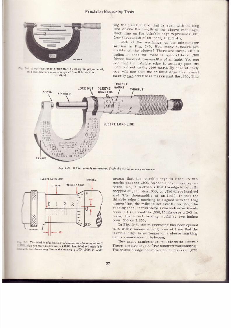
7/26/2019 Auto Service and Repair - Martin W. Stockel
http://slidepdf.com/reader/full/auto-service-and-repair-martin-w-stockel 27/224
Precision
Meosuring
Tools
t i l iple
ronge
micrometer.
By using the proper
anvi l
..ometer
cove¡s
o ronge
ol lrom 0
in,
to 4 in,
(Lulkin)
ing
the
thimble
line
that is
even
with
the
long
line
drawn
the
length
of the
sleeve
markings.
Each
l ine
on the
thimble
edge
represents
.001
(one
thousandth
of
an inch),
Fig.
2-44.
Look
at
the markings
on the
micrometer
sect ion
in
Fig.
2-5.
How
many
numbers
are
vis ible
on
the
sleeve?
There
are three. This
3
indicates that the mike is open at least .300
(three
hundred
thousandths
of
an inch).
you
ca n
see
that
the
thimble
edge
is
actually past
th e
.300
but
not
to the
.400
mark. By
eareful
study
you
will
see that
the
thimble
edge
has
moved
exact ly
two
addit ional
marks
past
the
.300.
This
THIMBL
E
MARKS
6$75
.8125
29.9U
15.9375
J1.968?
Fig. 2-4A.
0-l in.
ou¡sidemicromeler.
THIMBL
E
ur
SLEEVE
LONG LINE
Study
he morkings
nd
port
nomes.
means
that
the
thimble
edge
is
lined
up two
marks
past
the
.300.
As each
sleeve
mark
repre-
sents
.025,
i t is
obvj .ous that
theedgeis
actual ly
stopped
at
.300
plus
.050,
or
.350
(threehundred
and f if ty
thousandths
of
an inch).
In
that the
thimble
edge
0 marking
is
aligned
with
the long
sleeve
1ine,
the mike
is
set exact ly
on.350.
The
reading
then, if
this were
a one inch mike
(reads
from 0-1
in. )
wouldbe.3S0. I f th iswere
a
2-3
in.
mike,
the
actual reading
would
be
two inches
plus
.350 or 2.350.
In Fig.
2-6,
the micrometer
has beenopened
to a
wider
measurement.
You
will
see that the
thimble
edge is
no
longer
on a sleeve marking
but is
somewhere in
between.
How
many
numbers
are visible
on the sleeve ?
There
are
f ive
or.500
(f ive
hundredthousandths).
The
thimble
edge has
movedthree
marks
or.0?5
LOCKNUT
SPINDLE
\
SLEEVE
NUMBERS
NVI
L
al
l¿
Nts .
,
1 .0111
'
.09l?
5
,156¿
7
2187
5
'5
25
5g
13
'---'r&;-
Tlu
s. l¡dF' ' l Co.
-
ArHür,
¡e s. *1.4.
¡ ü¡nt ts u.5.¡.
/
9,e81¿
11.343?
13
.4Ó5
¿
15.468?
1?.5311
;
19.593?
.i
31.656?
-. '
23 .7 r&7
,, '
SLEEVE
LONG LINE
"
j . . l
i
l ¡e
thinbleedgeñosmovedoc¡oss
he
s/eeve
up tothe
3
-
r
"
:
_s wo
mo¡e
s/eeve
morks
,050).
The
rhinble
0 mork
s in
'.
r
c
' -e
s/e."e
/ong
inesot/re
reodingis,.300+.050+0=.j50.
50
:
75
il ü
25
87 5
l6¿5
i87:
.Jt¿
.4 3
11
SLEEvE
THIMBLE
EDGE
27

7/26/2019 Auto Service and Repair - Martin W. Stockel
http://slidepdf.com/reader/full/auto-service-and-repair-martin-w-stockel 28/224
012 3 4
5
,
3.
Fig.2-6.
Thinble
edge
hos movedup
to ff te 5
(.500)
plus
three
mo¡e sleeve
no¡ks
(.075)
plus
l2 lh inble
no¡ks
( 012)
resul t ing
in a totol
reading ol .587.
past
the
.500
mark. This
makes
a total
of
.575.
The thimble edge has movedpastthethirdmark.
In
that the fourth
mark is notvisible, u¡e know it
is
somewhere
between
the third and
fourth
mark,
Fig. 2-6.
By
examining
the thimble
edge
marks,
Fig.
2-6,
you will
see
that the twelfthmarkis
aligned
with the sleeve
long line.
This means that
th e
thimble edge
has moved
twelve
thimble
marks
past
the
third
sleeve
mark. In that
each
thimble
mark
equals
.001
(one
thousandth
of an
inch) the
thimble has actualtry
moved
.012
(twelve
thou-
sandths of
an
inch)
past
the third sleeve
mark.
Your reading then
would be
.500
0argest
sleeve
number
visible)
PLUS
.075
(three
sleeve
marks
past
sleeve number)
PLUS.012
(twelve
thimble
marks
past
the third
sleeve
mark)
making a
total
reading of
.587
(five
hundred and
eighty-
seven thousandths
of an inch).
If
this
were a
3-4 in. micrometer, the actuaL
measurement
woul .dbe 3.58?.
Study
the
readings shown in
Fig.2-74.
Com-
pare your
answers
with those shown.
Make
your
readings in
four
steps. See
Fig. 2-?.
1. Read the largest sleeve numberthatisvisible
-
each one
indicates
.100.
Count the number of
full
sleeve
marks
past
th is number
-
each one
indicates.025.
Count the number of thimble
marks
past
this
last sleeve number.
Each
one
indicates
.001.
If the thimble
marks
are
not
quite
aligned
with
the sleeve long line, estim ate the
fraction
of
a mark.
4. Add the
readings
in
steps 1,
2 and 3.
The total
is the
correct
micrometer reading. Add
this
reading to the starting size
of the micrometer
being used.
If
the
mike
range
was
1-2
in., add
the
total
reading to 1.000
(one
nch),
F íg.2-7.
READING
MICROMETERRADUATED
IN
TEN
THOUSANDTHS
F
AN
¡NCH
The same reading technique as
that
just
de -
scribed is used
to read this type of micrometer.
Instead, however, of estimating
fractions of
a
thousandth
between thimble marks, a
VERNIER
scale
on
the sleeve makes
it
possible
to
accu-
1
il
l i
t+
I
I
I
I
.012+l
l+.:oo*l
l+
Fig.2-l . fhreesfeps
inreoding
ff iemic¡omefer.FhstreodinginA=.300,
secondreoding
inB=.050,thi rdread-
ing in
C
=
.Ot2
=
o
totol
reoding
ol ,362
(Three
hund¡ed
and
sixty-two
tfrousonds).
Fig.2-7A.¡=.t75,8=.599,C=.242y2or.2425.Notef[of inCrñel¡octioninone-fhousondtñisestimotedos
indicoted
by rhe thimblé mark.
28
.oso
-l
0 L2345

7/26/2019 Auto Service and Repair - Martin W. Stockel
http://slidepdf.com/reader/full/auto-service-and-repair-martin-w-stockel 29/224
Precision
Meosuring
oof
rately
divide
each
thousandth
into
ten
parts
or
one
ten-thousandth
of an inch.
The
vernier
consists
of
elevel.l
thin
tines
scribed
parallel
to
the
sleeve
long
line. They
ar e
roarked
0-10.
Whenever
the
thimble
marks
donot
fall
in
line with
the
long
sleeve
line
thus indi-
cating a fraction of one-thousandth ineh, care-
lully
examine
the
vernierlines.
One
of the
verni-
er
lines
will
be
aligned
with
one
of
the thimble
¡oarks.
When you
have
diseovered
the
specific
r¡ernier
line
that
is
aligned
with
athimble
mark,
:he
number
of that
particular
vernier
line will
:ndicate
the
number
of tenthousandthtobe
added
Fig.2-8,
Vernie¡
/ines
ore
sñown in
colo¡.
Note táot
vernier
line
Í{o.
3
is
the
only
one
exactly
in line
with
a thimble
mork,
your
'adins
would
hen
e 100
:1tr=-.;:li.-
.0003
¡hree
en hou-
:o
vour
initial
thimble
reading,
Fig.
2-g.
Examine
the
readings
shown in Fig. 2-9. Inboth instances
a fraction
of a
thousandth
is
ob -
nous
by
examining
the
thimble
marks.
By
check-
'rg
the
vernier,
you
can see
that
one
of the
ver-
::er
l ines
is
in
ali .nment
with
a
thimble
mark
-l'¡s
indicating
the
number
of
ten thousandth
over
--be
thimble
thousandth
reading.
Compare
your
:eadings
with
those
shown,
Fig.
2-g.
LIHEN
USING
NY
MEASURING
OOL
Always
thoroughly
clean the
work
to
be
"easured. This
assures
you
of
accurate
work
¡nd
reduces
wear
on
the
workingtips
ofthe tool.
LIs¡NG
UTSIDE
ICROMETER
\\'tren
measuring
small
objects, grasp
the
*'erometer
in
the
right
hand,
and
at
the same
:¡ae
insert
the
object
to be
measured
between
:¡e
anvil
and
spindle
end
While
holding
the work
e€ainst
the
anvil,
turn
the
thimble
with
the
Fig,
2-9,
ln
A,
vernier
/ine
No.
5
is oligned
with
o
thimble
mo*;
reading
would
be
.075
+ ,005
+
.0005
=
.O¿OS.
n
B,
vernier
ine
No .
4
is
al igned;
reoding
wovld
be .200
+
.025
+
,012'+
.0004
=
.2374,
thumb
and forefinger
unti.l
the
spindle
engages
the
object.
Do
not
clamp
the micrometertight
-
use
only
enough pressure
on the
thimble
to
cause
the work
to
ju-El
fit
between
the
anvil
and
spindle.
Slip
the
objeet
inandoutof
the microm-
eter
while
giving
the
thimble
a final
adjustment.
The
work
must
slip
throughthe
micrometerwith
a qy ljght force.
When
satisfied
that
your
adjustment
is
cor-
rect,
read
the
micrometer
setting.
BE
CAREFUL
THAT
YOU
DO
NOT
MOVE
THEADJUSTMENT,
Fig.
2-
10.
o----J_
(o
----_r
co
__r
{
___r
,¿',
---+-20
F-F
( , -F
N
---a-
É
-------L_
'o
futs
-lrlTE
Fig. 2J0. Miking a small hole gauge. The heel o{ ¡he ñond sup-
porfs
tlre
mic¡omete¡
frome
while
the ¡humb
ond
lorelinger
turn
rfie r[in6le.
lL.
S. Srorrer)
To
measure
larger
objects,
grasp
the frame
of
the
micrometer
and
slip the
micrometerover
the work
while
adjusting
the
thimble.
Slip
the
mike
back
and forth
over
the work
until
verv
light
resistance
is fett,
Fig.
2-10A.
29

7/26/2019 Auto Service and Repair - Martin W. Stockel
http://slidepdf.com/reader/full/auto-service-and-repair-martin-w-stockel 30/224
Fig. 2-10A. Mikingo c¡onkshol t.Notice
how the mike
s held.
Some micrometers
have
a ratchet
clutch
knob
on the
end of the thimble
to allow the
user
to bring
the splndle down
against the work
with
the
same
amount of tension each
time.
As
the micrometer
is sl ipped back
and
forth
over the work,
it should be
rocked from
side to
side a tr if le
to make
certain
the
spindle
cannot
be
closed an addi t ional
amount,
Fig.
2-11.
I
I
I
I
I
I
Fig. 2-l l . ln
A,
miuometer
s sl ipped bock ond lorth over object.
ln B, micrometer s
rocked from
side
to
side
lo moke
certoin the
smol lesf diometer s {ound.
Rocking
s
octuol ly very
sl ight.
PRACTICE
S
NECESSARY
Measure
objects
of a known
diameter
until
you
have mastered
the
feel
of using
a
microm-
eter. Keep
practicing
until you
are
completely
confident
of
your
readings.
REMEMBER
-
A
MECHANIC
MUST
BE
ABLE TO MAKE
ACCU-
RATE
MICROMETER
READINGS.
HANDLE
TH E
MICROMETER
WITH
CARE.
NEVER
STORE A
MIKE
WITH THE
ANVIL
AND
SPINDLE
TIP
TOUCHING
(this
encourages
rusting
between
the tips). CLEAN YOUR WORK BEFORE
MEASURING.
INSIDE
MICROMETER
The
inside micrometer
is used for
making
measurements
in
cylinder bores,
brake drums,
large
bushings,
etc. ,
Fig.2-L2.
lnside micrometu.
By
chonging
ods, his
set
wi l l meo-
sure hom
2
to 8 in,
lL. S. Sto¡refi)
\
\
30
Fis.2-12.

7/26/2019 Auto Service and Repair - Martin W. Stockel
http://slidepdf.com/reader/full/auto-service-and-repair-martin-w-stockel 31/224
Precision Meosur ingTools
It
is read in the same manner as the outside
=Licrometer
and the same
feel is
required.
When
:neasur ing,
rock the ins ide
mike
from
side to
side
at the same t ime keeping
the anvil f irmly
against
one side of the bore. While the free
en d
:s being
rocked, it must
also be t ipped in and
out. The
rocking
allows
you
to locate
the
widest
:art of the bore whi le the t ipping assures you
:hat
the micrometer is
at r ight angles to the
:ore,
Fig.2-13.
An
extension handle
permits
the use
of an
-nside
micrometer
in
a bore
too smal l to hand
:o1d
the
tool.
To
use, the base
is
pressed
against the work
(after
cleaning) and
the
spindle is run down
into
the hole
to be measured.
It
is read
líke an outs ide micrometer,
th e
only dif ference
being
that the
sleeve
marks
run in a reverse
direct ion,
Fig.
2-15.
Fig.2-15.
Using
the micrometer
epth gouge.
The
6ose is he/d
l i rnly
ogoinst the
work ond the thimble ¡urned
unt i l lhe rod con.
focls fhe
shou/der.
DIAL
GAUGE R NDICATOR
The
dial indicator
is a
precis ion
tool de-
signed to measure movements in
thousandths
of
an inch.
Some common uses are
cheeking
en d
play
in
shaf ts, backlash between
gears,
valve
I if t ,
shaft
run-out,
taper
in
cylinders,
etc.
Use
care
in
the handling of this
tool as
it is
sensit ive and
easily damaged.
When
not in
us e
keep in
a
protect ive
case.
Dial
indicator faces
are calibrated
in thou-
sandths of an ineh. Various
type dial markings
are available. Ranges (distance over which th e
indicator
can
be
used)
vary
also depending on
the inst rument , Fig.
2-16.
Various mounting
arms, swivels and adapters
are
provided
so
that
the indicator
can
be used
on various setups.
When
using a dial indicator, be
certain
that
it is f irmly
mounted and
that the standard
E,g.2-13.
lnside
micromerer
must
6e
rocked f rom side fo
side
os
- A, whi le
ol fhe some f ime i t must be f ipped
os sf iown
in
8.
Bolh
movements
re relot ively sl ight .
MICROMETER
EPTHGAUGE
This
is
a
handy
tool
for reading
the depth of
-.-ots,
spl ines,
c ou
nt e rb
o r e s,
ho1es,
etc. ,
. ' -2, .
2- t4.
2-14,
Microneter depth
gouge.
The
tonge
con 6e ínc¡eosed
by using
longer
rods,
'j:\
ii'
,.,. r
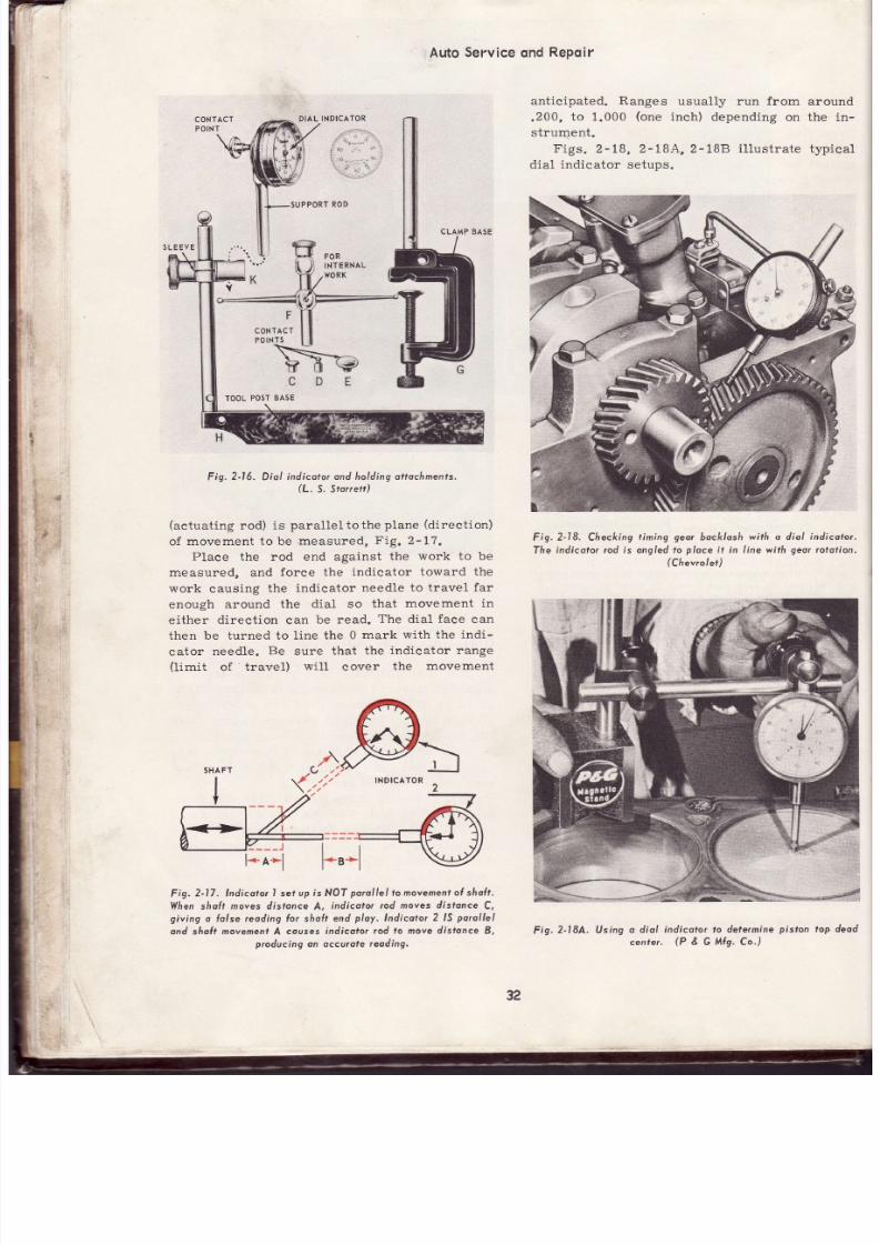
7/26/2019 Auto Service and Repair - Martin W. Stockel
http://slidepdf.com/reader/full/auto-service-and-repair-martin-w-stockel 32/224
DIAL
NDICATOR
CLAMP BASE
Auto
Service
ond
Repoir
anticipated. Ranges
usually run from around
.200,
to
1.000
(one
inch)
depending on the
in-
strurnent.
F igs. 2-18, 2-184,2-1BB i l lustrate t lp ica l
dial
ind icator setups.
Fig.2-18. Checking
timing
geor
6oc/<loshwirh o dio l
indicoto¡.
The
indícolor
rod
ís ongled
o
ploce
t in I ine with
geor
rotol ion.
(Chevrolet)
Fig. 2J6, Diol
in¿icotor ond holding ottochmenls.
(L.
S. 5to¡¡ett)
(actuat ing
rod) is
paral le l tothe
plane
(direct ion)
of
movement to be
,measured,
I. ig.
2- I7.
Place
the rod end against
the
work
to be
measured, and
force the
indicator toward
th e
work
causing
the
indicator
needle to
travel far
enough around
the dial
so that
movement
in
either direct ion can be read. The dial face ca n
then be turned to l ine the
0
mark
with
the
indi-
cator
needle.
Be
sure that
the
indicator range
(limit
of
.
travel)
wil l
cover
the
movement
INDICATOR
---- t
l*'*l
Fig.
2-17. lndico¡or sef
up
is
NOT
porolle l
to
movement l sholt.
When sholt
moves disfonce
A,
indicotor rod moves
dístonce
C,
giv ing
a hlse reoding
Íor
sholt
end
ploy,
Indicotor
2
lS
porol le l
and sholt
movement
A couses
indicoto¡ od
to move distonce
B,
producing
on occurole
reoding'
Fis.
2-18A. Using
o diol
center.
indicotor lo detetmine
pislon
top deod
(P GMlg.Co')
32
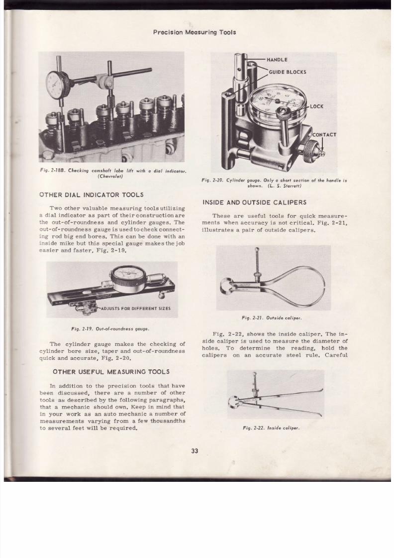
7/26/2019 Auto Service and Repair - Martin W. Stockel
http://slidepdf.com/reader/full/auto-service-and-repair-martin-w-stockel 33/224
Precision
Meosur ingTools
Fig.2-188.
Checking comshol t
ohe t¡ft w¡rh
o
¿iol indicotor,
(Chevrolet)
OTHER
DIAL INDICATOR
OOLS
Two
other valuable measuring
toolsuti l iz ing
-
dia l indicator
as
part
of theirconstruct ionare
:re
out-of-roundness
and
cylinder
gauges.
Th e
: : t
- of-roundne
s
s
gauge
is
used to
check connect-
-:g
rod big
end bores.
This
can
be done
with
an
-rs ide
mike
but th is special
gauge
makesthe
job
:as ier
and faster , Fig. 2-19.
F g. 2-l
9.
Oul-ol-roundness
ouge.
The
cylinder
gauge
makes
the checking
of
e¡'Iinder bore size, taper and out-of-roundness
quick
and accurate,
Fig.2-20.
OTHERUSEFULMEASURING OOLS
In
addition to the
precision
tools that
have
'ceen
discussed, there are
a number
of other
tools
as described
by
the
following
paragraphs,
that
a
mechanic
should own.
Keep in mind that
:n your
work
as an auto
mechanic
a number of
rreasurements
varying
from
a
few
thousandths
:o several feet wil l be required.
Fig.2-20.
Cyl inder
gouge.
Only o sho¡f secl ion ol the hondle
is
shown. lL. 5. Storre*)
INSIDE
AND OUTSIDECALIPERS
These
are useful
tooLs
for quick
measure-
ments
when
aecuracy is not
cr i t ical
.
I . í9.
2-21,
i l lustrates
a
pair
of outs ide
cal ipers.
Fig. 2-21.
Ourside oliper.
Fig.
2-22, shows the ins ide cal iper .
The in-
s ide
cal iper
is used to measure the diameter of
holes.
To
determine the reading,
hold the
calipers
on an accurate steel rule. Careful
ADJUSTs ORDIFFERENT IZES
33
F
g.
2-22. lnside
co/iper.

7/26/2019 Auto Service and Repair - Martin W. Stockel
http://slidepdf.com/reader/full/auto-service-and-repair-martin-w-stockel 34/224
Auto Serv¡ce
qnd
Repq¡r
measuring
across the
points
(very
light touch)
with
an outside micrometer wil l
give
a
more
accurate reading,
Fig.
2-22.
DIVIDERS
Dividers
are somewhat
like
calipers
bu t
have straight shanks and pointed ends. Theyare
handy for
making
circles,
taking surface mea-
surements,
etc.
Fig.
2-23, i l lustrates a
pai r
of
divide rs.
Fig.2-23. Divíde¡s. Poinfs musl
óe shorp.
FEELERGAUGES
Feeler
or thickness
gauges
are
thin
str ips
of specially hardened
and
ground
steel,
with
the
thickness marked in
thousandths
ofaninch.
They
are used to
check c learances
between
two
parts
sueh as valve
gap, piston
ring side and end
ga p
clearance, etc.
They
are available in sets
as
shown
in
Fig.
2-24, and also in
12
in.
or
longer
lengths.
Fig. 2-25.
l l i re
gouge
sef for
checking
spoú
plug
gop.
WIRE
GAUGE
The
wire
gauge
s
inef fectath icknessgauge,
but
i.nstead
of a
thin f lat
strip of
steel,
wires
of
varying
diameter
make
up the typical
set.
It
is
excellent for
checking
spark
plug
gap,
distributor
point gap,
etc. ,
Fig.
2-25.
SCREW
ITCH
GAUGE
This
is
a handy
tool for
determining
th e
number
of threads
per
inch
on
bolts,
screws and
studs,
I . ig.2-26.
Fig.2-26. Screw
pi fcá gouge,
The
fi ¡st
o¡
smol l
number
ndicotes
the numherol threods
per
inch.
Iñe second
number indicates
the
douhle depth
ol ¡he threads.
ffry* ***
2-27.
Telescoping
gouges.
The
gouges
s/rown
wi l l
cove¡
range rom 1
2
ro 2-1
2
in.
(L.
S. Srorref)
ig,2-24.
Fee/er
gouge
sef.
(Owottono
Tools)
34
Fis.
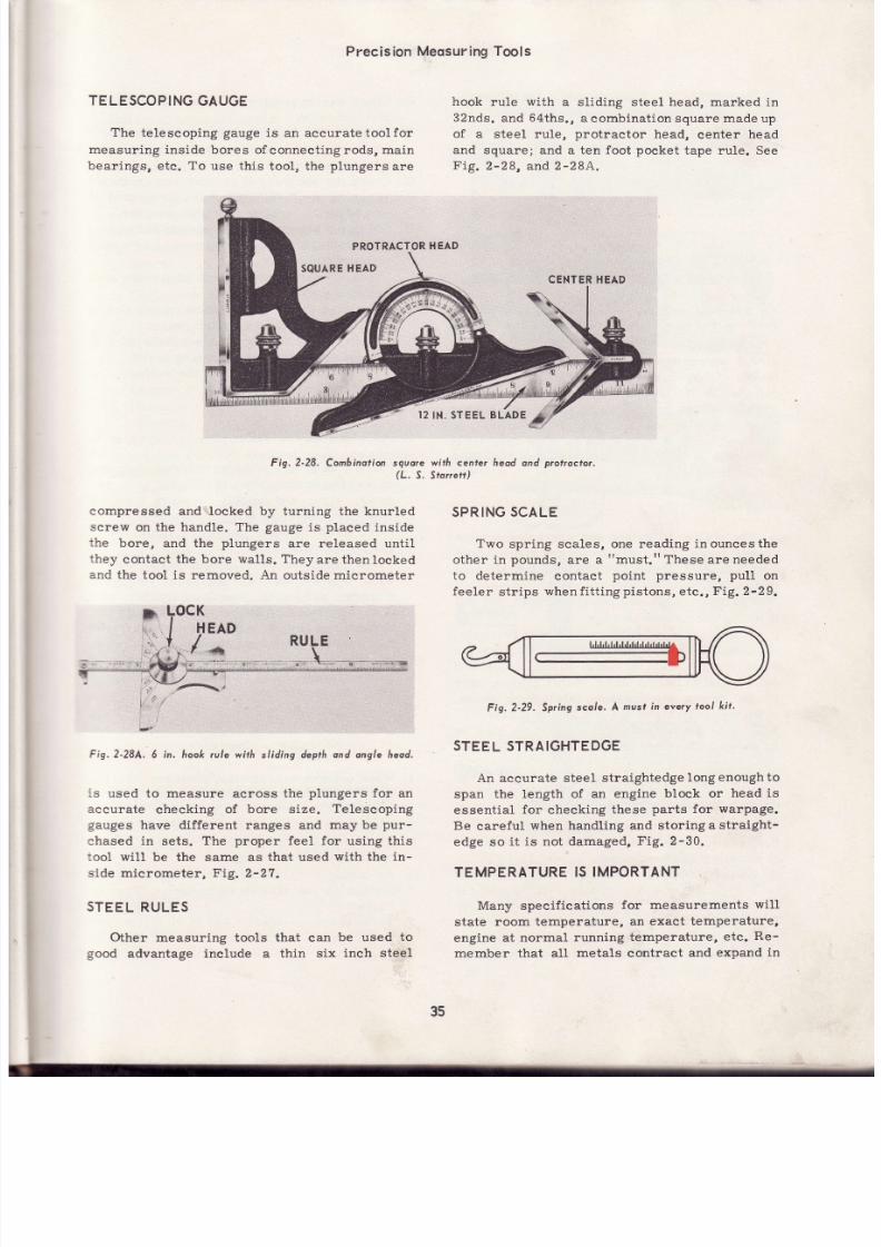
7/26/2019 Auto Service and Repair - Martin W. Stockel
http://slidepdf.com/reader/full/auto-service-and-repair-martin-w-stockel 35/224
Precision
Meosur ingTools
TELESCOPING
AUGE
The
telescoping
gauge
is an accuratetool for
measuring inside bores of
connecting rods,
main
bearings,
etc.
To
use this too1, the
plungers
ar e
PROTRACTOR
EA D
SQUARE EAD
hook
rule
with
a sliding steel head,
marked
in
32nds.
and
64ths.,
a
combination square
made
up
of
a steel rule,
protractor
head,
center
head
and square; and a ten foot
tape rule. See
Fig.
2-28,
and
2-284.
CENTER
EA D
Fig.
2-28.
Combinotion
squore with cenfer heod ond
protroctor.
(L.
S.
Sror¡etr)
compressed
and locked by turning the knurled
screw
on the handle.
The
gauge
is
placed
inside
the
bore, and the
plungers
are released unti l
they
contact
the bore wal ls . Theyarethenlocked
and
the tool
is removed.
An
outside mierometer
K
HEAD
l
RULE
-r X
Fig.2-28A.
6 in. hook rule wi¡h
sl id ing
depth and ongle heod.
is
used
to measure across the
plungers
for an
aceurate
checking
of
bore
size.
Telescoping
gauges
have different ranges
and
may
be
pur-
ehased in sets. The proper feel for using this
tool
wil l
be the
same as that used
with
the
in -
s ide
mierometer,
Fig. 2-27.
STEEL
RULES
Other measuring tools that can
be used
to
good
advantage in clude a thin six
inch steel
SPRINGSCALE
Two
spr ing
scales,
one reading
inouncesthe
other in
pounds,
are a
must.
These
are
needed
to
determine
contact
point pressure,
puII
on
feeler
str ips
whenfi t t i .ngpis tons, etc .,Fig.
2-29.
Fig.2-29.
Spring
scole' A
must
in every
tool k i t .
STEEL
STRAIGHTEDGE
An accurate steel
straightedge
longenoughto
span
the length of an engine
block or
head
is
essential
for checking
these
parts
for
warpage.
Be
eareful
when handling
and storing
a straight-
edge so i t is not damaged, Fig. 2-30.
TEMPERATURE
IS IMPORTANT
Many
specif ications
for measurements
will
state room temperature,
an exact
temperature,
engine at
normal
running
temperature,
etc.
Re -
member that all
metals
contract
and
expand
in
35

7/26/2019 Auto Service and Repair - Martin W. Stockel
http://slidepdf.com/reader/full/auto-service-and-repair-martin-w-stockel 36/224
-
Auto
Service
ond
RePoir
Fie.2-30.
Steel
stroigtrtedge.
A-sguore
edge.
8-Bevel
edge. C'
Bevel
and ruled edge.
These
ore ovailable
in diÍÍerent
lengths.
direct
proport ion
to their
temperature.
This
makes
it imperative that
temperature
specifi-
cations
be
followed
when making
precision
measurements and settings. Your measuring
tools themselves
can
be
affeeted
by
extremes
of
heat
and
cold.
If your tools
must be used
when
very cold
or very
hot,
eheck
them
for accuracy
before
using.
SUMMARY
The abitity
to select
and correctly
use
the
proper
measuring
tools
to secure
highly accu-
rate measurements,
is a
MUST
-for
all auto
mechanics.
Preeision tools require
cleanl iness,
careful
handling and proper storage.
The mechanic
should
own,
or
have available,
outside
and
inside
micrometers,
micrometer
depth
gauge,
dial
indicator
setup,
inside
and
outside calipers,
dividers,
feeler
gauges, wire
gauge¡
screw
pitch gauge,
telescoping
gauge,
steel rules,
straightedge
and spring
scales.
Other specialized
measuring
tools
may be
acquired
as
the
need
dictates.
SUGGESTEDRACTICE
OBS
A.'Practice
reading
a
micrometer
unt i l
youcan
make a correct reading everY time.
B. Use an outside
micrometer
to
measure sever-
al objects
of known
size.
C.
Measure the
inside diameter
of
a
cylinder
of
a cylinder
of a
known size
with
your
inside
micrometer.
D. Using a
depth
gauge, measure
the
distance
from the surface
of a cylinder
head to the
top of a valve
guide.
fValve-in-head
engine.)
G.
Check
the
run-out on a
camshaft
by using
a
dial
indicator.
Measure the
inside diameter
of a
wrist
pin
bore using
a telescoping
gauge
and an
outside
micrometer.
Check
the accuracy
of an
outside
micrometer
by using a
STANDARD
(measuring
rod of
exact length) furnished for this purpose.
Check
the
accuracy of
aninside
mikebyusing
the outside
micrometer
youhave
just
checked
with the standard.
Check
the
gap
between
spark
plugelectrodes
by using
a
wire
gauge.
Determine the number
of threads
per
inch on
a bolt
by using a
screw
pitch gauge.
Determine
the tension
on a set
of distributor
contact
points
by using a spring
scale.
L. With a straightedge,
check
the surfaee
of a
cylinder
block
for warpage.
SUGGESTED
CTIVITIES
1.
Place a
wrist
pin
in
thefreezereompartment
of
a refrigerator.
When thoroughly
cold,
re-
move,
wipe,
and
quickly measure
both the
diameter and
length
using an
outside
microm-
eter.
(Hold
the
wrist
pin
with a
cloth.)
Write
down
your
readings.
Now
place
the
wrist
pin
in
boiling
water.
When
hot, remove,
dry and
quickly recheck
diameter
and
length.
Was there adifference?
If so,
how much? What
does
this
indicate?
2. Explain how to read a micrometer toafriend
that
does
not know
how. Have
himtrya
read-
ing
and continue
to
help him until
he does
it
correctly.
By
doing
this
you
will reinforce
your
own
knowledge.
OUIZ
-
ChoPter
1.
When using
a
micrometer,
make surethatthe
tool
is
clamped
around
the
worktightly.
True
or
False
?
2. Measuring
tools
are rustproof.
True or
False
?
3.
A micrometer
should
be
checked
if accidentally
dropPed.
4.
An inside
micrometer
is read
in
the
same
fashion as
the outside
micrometer.
True or
Fa1se
?
5.
To measure
an object
3.500 in
diameter,
yo u
would
use a
micrometer
with a range
of
to
i l l ry i
f:--rW
ll
l
, ** -1
E.
F.
i
ü'$
*-J
I
-;;
-
"*
-"'-'"ttt*
J
m#bffiffi
H.
I.
J.
K.
i
".|
36
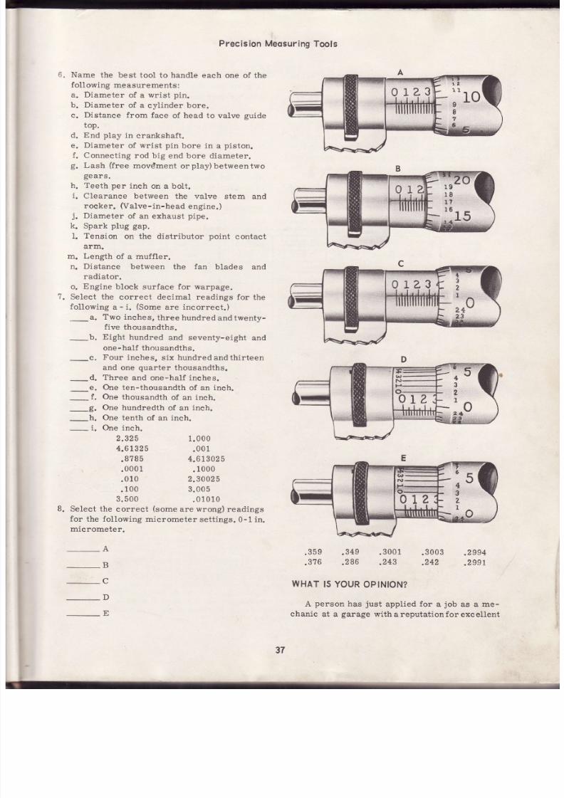
7/26/2019 Auto Service and Repair - Martin W. Stockel
http://slidepdf.com/reader/full/auto-service-and-repair-martin-w-stockel 37/224
5.
Name
the best tool
to
handle
each
one of the
following
measurements
:
a. Diameter
of
a
wrist
pin.
b. Diameter
of
a
cylinder
bore.
c.
Distance
from face
of
head
to valve
guide
top.
d. End play in crankshaft.
e.
Diameter
of
wrist
pin
bore in
a
piston.
f. Connecting
rod
big end bore
diameter.
g.
Lash
free
movdment
orplay)betweentwo
gears.
Teeth per
inch
on
a
bolt.
Clearance between
the valve
stem and
rocker.
Valve-in-head
engi.ne.)
Diameter
of an exhaust
pipe.
Spark
plug gap.
Tension
on the
distr ibutor
point
contact
1.
arm.
m. Length
of a muffler.
n. Distance between the fan blades an d
radiator.
o.
Engine
block
surface for warpage.
Select the
correct
deeimal
readings for
th e
following
a
-
i.
Some
are
incorrect.)
- -a.
Two inches,
three hundred
andtwenty-
five thousandths.
_b.
Eight
hundred
and seventy-eight
an d
one-half
thousandths.
Precision Meosur ing
Tools
.359
.376
h.
i
i
k.
1.
_c.
_d.
r.
_9.
_h.
_ i.
Four
inches,
six hundred
andthirteen
and one
quarter
thousandths.
Three
and one-half inches.
One
ten-thousandth
of an ineh.
One thousandth of an inch.
One hundredth
of an
inch.
One
tenth
of an
inch.
One
inch.
2.325
4.6t325
.8
785
.000
1
.010
1.000
.001
4.613025
.1000
2.3
0025
a
.100
3.005
3.500
.01010
Select the
correct
some
are
wrong)
readings
for
the
fol lowing
micrometer
sett ings.
0-1 in.
micrometer.
WHAT
S
YOUR
OPINION?
A
person
has
just
applied
for
a
job
as
a
me-
chanic
at a
garage
withareputationfor
excellent
.349
.286
.300
1
.243
.3003
.2994
.242
.299L
-E
37

7/26/2019 Auto Service and Repair - Martin W. Stockel
http://slidepdf.com/reader/full/auto-service-and-repair-martin-w-stockel 38/224
. +4ís.1:
Aqidservice
ond
Repoir
work.
The owner is
interested;
there
is
an
opening;.ihe
pay
is
good.
So
the
owner intro-
duces
th*e.app$.icant
o
you,
who,
as
shop super-
visor,
wil l
be expected
to
evaluate thispersonts
worth
as a mechanic.
You walk to a nearby service bench, open
your
tool
chest
and lay
out a
selection
of
measuring
tools.
You
indicate
a specific
cylin-
der bore
you
would
like miked,
and inform
the
applicant to
choose the
tools
and make
the
measurement.
The applicant
picks
up
an inside
caliper and
a six inch
steel rule,
adjusts the
caliper
in
the
bore, then
plaees
the
caliper
on
the face
of
the
six inch
rule
and,
after
some
squinting,
informs
you
that
the
bore
diameter
is
iust
a
whisker
over four
inches.
The
actual
bore
diameter
is
4.030.
What
do
you
think
of the
applicantfs
ability?
Will
you
recommend hiring this person? If ,not, why?
REMEMBER:
No
one
can be termed
a
top-notch
mechanic
who is
not fámiliar
withandcompetentinthe
us e
of measuring
tools
used
in
the trade.
youcan
be
proud
of
your
abil ity
to
make
precision
mea-
surements
-
it
is
the
mark
of a fine
mechanic,l
_6.*
GM 260-M)
.{GM
28O-M)
(cM
290-M}
(cM
3OO_M}
customary
(¡nch)
bolts
-
tdentif¡cat¡on
marks
correspond
o bott
l [t iT
STRENGTH
,t. ngt¡'rn r áing
nu.b
represent ncreasing
trength.
tDENTlFlcATloN
I
*b
vletr¡c olts ldent¡ficat¡on
lass umbers
orrespond
o bolt
strength
Increasing
umbers
epresent
ncreas¡ng
trength.
IDENTIFICATION MARKS
(4 }
f ig.3-A. Clro¡f
shows typicol torgue
or
cop
screws with ¡hreods cleon ond dry,
Reduce
orque by
l0
percent il threods
ore
oiled;
reduce by
20
percent
i( new,
ploted
fosleners ore used lo¡
vorisus
losrener
srodes.
ALWAYS FOLLOW
MANUFAC.TURER'S ORQUE SPECIFICATIONSFOR THE
EXACT
JOB AT
HAND.
A-Cop
screws, 6olts ctd nuls dre
morked
with eif f ier
/ ines or
numbets
o
indiccire hei¡
re lot ive strength.
B-Cuslomory
(inchl
bolt
morkings.
Note
trrot the strength
grode)
corresponds
o the numbe¡
of l ines.
fhere
ore olways two / ines less ¡hon the octuol
grade.
Q, -
Me¡¡ic
bolr.markings. he
higher.the
grode
(cuslomory)
or number
melr ic),
the
greoter
he slrenglh.
(Americon
Motors
Generol
Mofors)
SlendardTorque Spec¡fical¡ ons
nd
CapscrewMarkings
Chert
A
CAPSCFEW
EADMANKINGS
CAPSCBEW
BOOY
rZ E
Inches Thrۇd
SAEGRAOE
or
2
(Us6d
f,íisqu€ñtly)
SAEGRADE
(Us6d
Fr6auontlv)
SAE GRADE
6or 7
(Us€d.tf imos)
SAE
GRAOE 8
(Uséd
Ffsquoñtly)
Torque
Torque
Torque T,ofque
FI-Lb
Nm
Ft.Lb
Nm Ft-Lb.
Nm
FI.Lb
Nm
il¡nuladu6r's má¡ks may v¡ry
Tñrcelina ma.kings
on h6ads.
I
4-20
5 6,7791
8.1 €
I
10
0.4465
3.5582
t0 r
3.5582
t2
16.2698
18.9815
SAElor2 SAEs
SAESor?
dto saEGfsdo .
4¡r'+rÉ¡
r.avtY)
5./16-18
-ú
l3
1 .9f40
17.6256
7
9
23.0449
25.7605
I 25.7605
24
27
32.5396
36
6071
3/a'16
.
-24
20
24.4047
27.1164
31
35
42.0304
47.4536
34
46.0978
49 66.4351
7 16-14
|
'24
37.9629
40.67 5
49
66,.435
74.57 0
74.5100 10
ro5.7538
.7/¿=13
-20
3S
52.8769
55.5885
75
85
01.6863
15.2445
85 1 1
5.2445 10 5
12 0
r42.36@
162.6960
rrr9:]i
5l 69.1 67
74.51ú
11 0
r2 0
49.1
80
62.6960
12 0
162.6960
17 0
210.1
90
230.4860
5/8-1
1
-1 8
83
95
11
2.5329
128.8027
15 0
17 0
203.3700
230.4860
161
226.4186
2r 0
244
284.7180
325.3920
3/4-10
..
-16
r0 5
11 5
r42.3609
r55.9170
27 0
295
366.0660
399.9610
2AO 3t9.6240
42 0
508.4250
569.4360
r6 0
17 5
216.9280
231.2650
535.541
589.7730
44 0
596.5520
60 5
67 5
820.2590
91 .1 50
I
235
25 0
31
.61 0
3389500
59 0
66 0
7993220
894.8280
660
894.8280
99 0
l233.7tAQ
| 342.2420
'li.
38

7/26/2019 Auto Service and Repair - Martin W. Stockel
http://slidepdf.com/reader/full/auto-service-and-repair-martin-w-stockel 39/224
INCREASING
MPORTANCE
¡
In
the
modern
car, ever inereasing
horse-
power
and
road
speeds
subject
the
various
components
to
heavy
loads,
high
frequency
vibrat ion
and
severe
stress. As
a result ,
fasten-
er
(nuts,
boLts,
screws,
etc.)
design,
material
and
torque
sett ings,
once of relat ively small
interest
to
the mechanic,
have
assumed
a
posi-
t ion
of major importance.
It is
important
that the
mechanic
familiarize
himself
with
the
various t¡pes,
materials
used
in
their
construct ion,
uses,
and
proper
in-
stallat ion.
READ
CAREFULLY
Be
sure to
read
this
chapter
carefully.
Study
the
various fasteners,
their markings
and uses
until you
can recognize
them immediately.
Pay
particular
attention to
the
section
on toroue
wrenches.
MACHINE
SCREWS
Machine
screú S
are
used without
nuts. They
are
passed
through
one
part
and threaded
into
CLEARANCE
HOLE
A
TH R
EAD ED
u^t E
B
Fig.
3-l,
Cop screw.
Cop screw s
possed
hrough
cleorancehole
in
port
A
and threoded
into
part
B,
ooooooo
HHHHHó
LAT OVAL
FILLISTER
ROUND
CLUTCH
FLUTED
Typicol
mehine
screws.
Four
heods
at r ight i l lustrate
vorious
openings
or lurning
tools,
PAN HEAO ROUNDHEAD
,,_. f-,. A
HE
=
EF
Fig.
3-3, Typicol
sÁeet
mefol
screws.
SELF-TAPPING
OR SHEET
METAL
SCREWS
Siireet
metal
screws
are used
to fasten
thin
met¿. parts
together
and for
attaehing
various
items
to
¡ireet
metal. They
are much
faster
an d
less
expensive
than
bolts , Fig.
3-3.
Chapfer
3
FASTEN
RS,
TORQUE RENCHES
HE X
Fis.3-2.
another.
When
drawn
up, the
two parts
are then
held
in
fi rm
contact. Fig.
3-1,
i l lustrates
th e
use
of
a
cap screw
(machine
screw
with
a
hexagonal
head).
There
are
many
different
types
of machine
screws
and
screw
heads.
F ig.
g-Z
shows
a
number
of those
in
common
use.
39

7/26/2019 Auto Service and Repair - Martin W. Stockel
http://slidepdf.com/reader/full/auto-service-and-repair-martin-w-stockel 40/224
Auto Service
ond
Repoir
To
use
a
sheet metal
serew,
a hole,
that is
sl ightly
smaller
than
the minor
diameter
(diam-
eter
of the
screw i f thethreadswereground
of f ) ,
is
either
drilled
or
punched
through
a
piece
of
metal.
The punched
hole
provides
more
thread-
ing area and when the screw is drawn up, th e
hole
attempts
to
close thus providing
greater
grippi.ng
power.
Fig.
3-4.
Fig.3-4,
Screw
posses
Íreely through
A
ond
cuts threods
in
punched
hole in
B. Wñensc¡ew
tightens,
punched
metol draws
up
ond in,
providing
o
sécu¡e
grip,
C.
BOLT
A
bolt is
a metal
rod
that has
a head
at one
end and
a screw
thread
to
take
a nut
at the
other. The
bolt is
passed
through
the
parts
to
be
joined
then
the
nut is
installed
and drawn
up,
thus holding
the
parts
together, Fig. 3-4A.
-
NU f
-BOLT
Fig.
3-4A.
Using o bol¡ to hold
two
ports
together,
STUDS
A
stud
iS
a metal
rod,
threaded
onboth
ends.
The
stud
is
turned
ínto
a threaded
hole
in
a
part.
The
other
part
is
slipped
over
the
stud
Fis'
3-5'
stud
hreadednin"':":
':"'i¿;'::':; over
stud' vtptoced
and a nut is turned down on the stud to seeure
the
part.
Studs
are
available
in many
lengths
and diameters.
Some have
a
coarse thread
on
one
end and
a
fine
thread
on the
other..Others
have
the
same
thread
on both
ends
and
in
some
eases,
this
thread
may
run
the
full
length
of
the
stud, F ig.
3-5.
A
stud
wrench
should
be
used
to install
or
remove
studs.
Re
careful
not
to
damage
the
threads.
If
no
stud wrench
is
available,
plaee
two
nuts
on
the
stud
and
"j"*t'
them
together
(turn
the
top
one
clockwise,
the bottomcounter-
clockwise
until
they
eome together).
place
a
wreneh on the lower nut to remove the stud, on
the
upper.nut
to install,
Fig.
3-6.
REMOVING
ROKEN
TUDS
R SCREWS
There
are
several
methods
that
mav
be
em -
ployed.
If
a fair portion
of
the
stud
projects
5CR
EW
40
Fig.3-6.
lJsing
iom
nuts
ond wrench
o remove
sfud.

7/26/2019 Auto Service and Repair - Martin W. Stockel
http://slidepdf.com/reader/full/auto-service-and-repair-martin-w-stockel 41/224
above
the
work,
it
may
be
gripped
with
vise_
grip
pliers,
or
a
small pipe
wrench
and
backed
out.
Where
the
portion
protruding
is
not
sufficient
to grasp
with
pliers
or wrench,
flat
surfaces
may
be
filed
to
take
a wrench,
or
a
slot
may
be
eut
to
allow
the
use
ofa
screwdriver,
Fig.
3_64
Detail A.
^fu
,Or-ffi
g
€
Fíg.3-6A.
Merñods
sed
n ¡emoving
roken
tud.
A_Srud
rorred
w f
led
llot.
B-Nut
welded
on.
C-punch
.d
ro
Á r.w
broken
piece. D-Screw xtroctor. E-lJsing top to remove hell.
-\nother
method
is
to
dril l
a hole
in
a,sect ion
of f,lat
steel, pLace
it
over
the
broken
stud
and
ineld
the
strip
to
the
stud.
A
nut
large
enough
to
f it
over
the
stud
can
also
be
welded
on .
,,r,-HEti
WELDING,
BE
CAREFUL
OF
FIRE
AND
D-{IÍ-{GE
TO
PARTS.
The
arc welder
does
th e
job
quickly
and
with
a
minimal
amount
of heat_
ing,
Fig.
3-6,4',
Detail
B.
When
the
stud
is
broken
off
flush
or
slight_
lv
below
the
surface,
you
may
use
a
thin
and
sharp
pointed
punch
and
try
driving
the
broken
seetion in a counterclockwise direet ion. Some_
times
the
stub
will
turn
out
easily.
If you
are
not
getting
results
-
stop
and
try
another
method,
Fig.
3-64,
Detail
C.
A
screw
extractor
can often
be
used with
good
results.
Center puneh
in
theEXACTcenter
of
the
stub.
Drill
through
the
stub with
a
small
diameter
drill
then
run
a drill
through
that
is
Fosteners
nd
Torque
Wrenches
B
I
ñ,-Q
\--2
/
-----1
a
trifle
smaller
than
the
stud
minor
diameter.
Lightly
tap
the
extractor
into
the
shell
that
remains
and
back
it
out
with
a wrench.
The
sharp
edges
on
the
flutes
will
grip
the
shell.
Do
not
exert
enough
force
on the
extractor
to
break
it
as
removal
of the
extractor
segmenr
could
present
a
real problem, Fig. 8-6A,Detail
D.
In
the
event
the
methods
previously
de_
scribed
fail,
select
the proper
tap
size
dril l
and
after
running
it
through
the
stub
shell,
care_
fully
tap
out
the
hole.
If
done properl¡
the
tap
will
remove
the
shell
threads
leaving
the
original
threads
in
the
hole
undamaged,
Fig.
3-64,
Deta i l
E.
When
drilling,
drilt
through
the
stub
only.
Do
not
drill
beyond
as
you
may
damage
some
part.
If
working
on
a
setup
where
metal
ehips
may
fall
into
a housing,
eoat
the
drill
and
tap
with
a heawy
eoat
of
sticky
grease
so that
the
chips wil l adhere to the tools.
USE
PENETRATING
IL
Regardless
of
the
method
of removal,
it
is
a
good
idea
to
apply
penetrating
oil
(a
special
Iight
oil
with
high
penetrating
powers
used
to
free
rusty
and
dirty parts)
to the
area
and give
it
a
few
minutes
to
work
in.
If
heat
is
noiin_
jurious
to
the
part,
an
applicatíon
of heat
will
also
help.
Use
caution
not
to
overheat.
If
in
doubt
as
to
the
effects
-
do
hot
apply
heat.
NEVER
USE
A TORCH
NEAR
A
GAS
TANK,
BATTERY OR OTHER FLAMMABLE MA-
TERIALS.
REPA¡RING
THREADS
Occasionally
threads,
both
external
and
in -
ternal,
are
only partially
stripped.
In such
cases
they
can
be readily
cleaned
up through
the
use
of
a thread
die
or atap,
Fig. B-BA.
When
threads
in
holes
are
damaged
beyond
repair,
one
of
three
things
can
be
done:
1.
The
hole
may
be
dril led
and tapped
to
the
next
suitable
oversize
and
a larger
diameter
cap screw or stud installed. Use a chart to
determine
the proper
size
(tap
size) to
use.
A
clearance
or
body
dril l
(a
dril l
the
size
of
the
bolts
major
diameter)
must
be
passed
through
the
attaching
part
to
al1ow
an
over-
s ize
cap
screw
to
be used,
F ig.
3-68.
2.
The hole
may
be
drilled
and
tapped
to
accepr
a threaded
plug.
The
plug
should
also be
.
EXTRACTOR
4l

7/26/2019 Auto Service and Repair - Martin W. Stockel
http://slidepdf.com/reader/full/auto-service-and-repair-martin-w-stockel 42/224
THREADS
TRIPPED
Fig,3-68.
Repoir ing
str ipped
rhreod
by
dri l l ing
ond |crpping
o
nexf
oversize.
dri l led and tapped
to
the
orig inal
screw
size.
A
special
self- tapping
plug
already
threaded
to the
original
size may
be
used.
you
merely
dril l
a hole
to
the
specif ied
size,
run
th e
threaded
plug
into
the
hole
by
using
a
ca p
serew
and
jam
nut. When
fully
seated,
th e
jam
nut is
loosened
and
the
cap screw
re -
moved, Fig.
3-6C.
+CAP
SCREW
_
LOCK OR
JAM NUT
THREADEDPLUG
DRILLED AND TAPPED
Fig.
3-6C. Insert ing
h¡eoded lug
to
repoir
str ipped f ireods.
Another method
makes
use
of
a
patented
coil wire insert called a Heli-Coil. The hole
is dril led
then
tapped
with a
speeial tap.
A
Heli-Coil
is
then inserted.
This brings
the
hole
back
to its
original diameter
andthread,
F igs.
3-6D
and
3-40.
Fig. 3-6D.
Repoir ing
str ipped hreods
by.usíng
o
Heli-Coil instol lot ion, Chrysler)
REMEMBER
Whenever
removing
a broken
screw
or re-
pairing
stripped
threads, proceed
carefully. A
frantic
or
careless
attempt
at
repair
can often
cause
serious
and
costly
trouble.
E2w
| - l
3.
_T
l l
BC
YI
-Y
NUTS
Nuts
are
manufactured
in a
variety
of sizes
and
styles. Nuts
for
automotive
use
are
general-
ly
hexagonal
in
shape
six
sided).
They
are used
on bolts
and
on
studs
and
obviously
must
be
of
the correct diameter and thread pitch threads
per
inch), F ig.
3-7.
SLOTTED
HE X
I
rffir
t_J
HE X
I
WING
NU T
SPEED
NU T
Fig. 3-7.
Common nuts.
fhe wing
nut
is insrol/ed
ond
removed
wirh
the Íingers.
Ilre speed
nut
js
used
in lastening
sáeef mefo/
or other pdús
not
requiring
the
strength
ol the
regulor
nut,
BOLT
AND
SCREW
ERMINOLOGY
Bolts
and
screws
may
be identified
by type,
length, major diameter, pitch threads per
inch),
Iength
of
thread,
class or
fi t ,
material,
tensi le
strength,
and wrench
size
needed,
F ig.
3-8.
l^* l ¡* l
Fig.
3-8.
Bol¡ and
sc¡ew fermino/ogy.
A-Pitch.
B-Minor
diometer.
C-Moior diometer.
D-Threod lengtfi.
E-Screw length.
F-Th¡eods
per
inch.
G-Heod size
measured
ocross
táé f/ots.
42
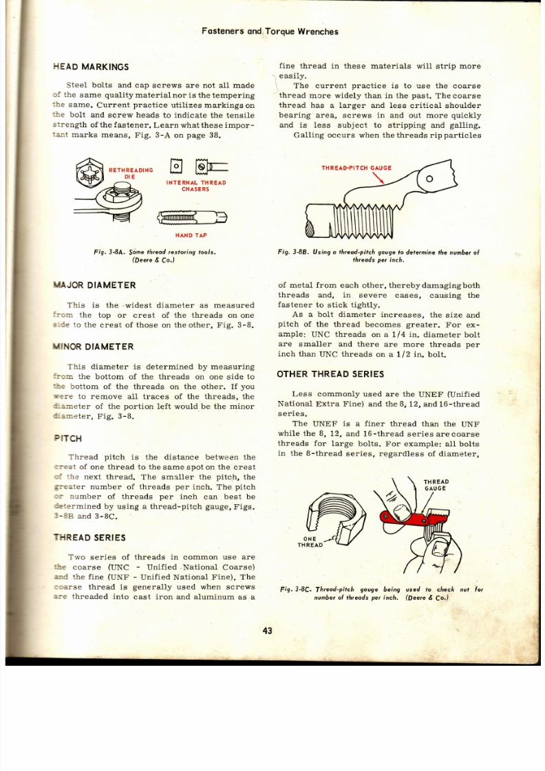
7/26/2019 Auto Service and Repair - Martin W. Stockel
http://slidepdf.com/reader/full/auto-service-and-repair-martin-w-stockel 43/224
r_
L
Fqsteners
nd
HEAD
MARKINGS
Steel
bolts and
cap screws are not
all
made
¡i
the
same quality
rnaterial
nor is the tempering
:he
same.
Current
pract ice
uti l izes markings
on
--re
bolt
and
screw
heads
to indicate
the tensile
::rength
of
the fastener.
Learn what these impor-
:alt marks means,
Fig.
3-A
on
page
38 .
-¡
easily.
RETH
READING
ñt E
HHÉ
INTERNAL
THREAD
CHASER5
HANDTA P
Fig.
3{.A.
Sdme
fireod esforing
toors.
(Deere Co.)
UAJOR
DIAMETER
This
is
the
.widest
diameter as measured
::o:n
the
top or crest
of
the threads on
on e
:-de
to the
crest of
those
on the other,
Fig.
3-8.
TilINOR
IAMETER
This
diameter
is determined by measuring
:: :n
the
bottom of the threads on
one side
to
t i:
bottom
of the threads
on
the
other. I f
yo u
;m'-: :e to remove all traces of the threads, the
'-=-neter
of the
port ion
left
would
be the
minor
'-a ineter ,
Fig.
3-B.
PfTCH
Thread
pitch
is the
distance between the
:rest
of
one
thread
to the same spot on the crest
: j :he
next thread.
The
smaller the
pitch,
th e
sreater number
of threads
per
inch.
The
pitch
::
number
of threads
per
inch
can
best
be
'e:ermined
by using a thread-pitch
gauge,
Figs.
1-3B
and 3-8C.
. ]THREAD
SERIES
Two
series of
threads in common
use are
úe
coarse
(UNC
-
Unif ied
.National
Coarse)
'-d
the f ine
(UNF
-
Unif ied National
Fine). The
:3arse
thread is
generally
used
when
screws
Fis.
-:e
threaded
into
cast
iron and aluminum
as a
Torque
Wrenches
f ine
thread in these
materials wil l str ip
more
The current
pract ice
is
to use the coarse
thread
mcre
widely
than in the
past.
The
coarse
thread
has
a larger and less
crit ical shoulder
bearing
area, screws in and
out
more
quickly
and is less
subject
to
str ipping and
gatling.
Gall ing occurs when the threads
ri.p
part icles
Fig. 3-88. Using
o
threod-pitch gouge
to
defe¡míne the number
ol
threods per inch.
of metal from
each other, therebydamagingboth
threads and, in
severe
cases, causing the
fastener
to st ick t ight ly.
As a bolt
diameter lncreases,
the size and
pitch
of the
thread becomes
greater.
For ex-
ample:
UNC
threads
on a Ll4
in.
diameter
bolt
are
smaller and there
are more
threads
pe r
inch
than
UNC
threads
on a 1/2 in. bolt .
OTHER
HREAD
ERIES
Less commonly used are the UNEF (Unif ied
National
Extra
Fine) and the B,
12, and
16-thread
s
er ies.
The
UNEF
is
a
finer
thread
than the
UNF
whi le the B,
12, and
16-thread
ser iesarecoarse
threads for
large
bolts.
For example: all bolts
in
the 8-thread
series, regardless
of diameter,
3-8C.
Ihreod-pitch
gouge
numbero{ threads
per
used
to check nut lo¡
(Dee¡e
E
Co.)
being
inch.
43

7/26/2019 Auto Service and Repair - Martin W. Stockel
http://slidepdf.com/reader/full/auto-service-and-repair-martin-w-stockel 44/224
Auto Service
and Repoir
I
I
.l
iii
have
8
threads per
inch. The
12-thread
series
bolts
have
12 threads per
inch,
etc.
Study
the
chart in Fig.
3-9.
Note
that
screws
under
Ll4 in.
in diameter
are designated
by
number
instead
of fractional
size.
CLASS
OR FIT
Thread
class
indicates
the
operating
clear_
ance
between
the
nut
internal
threads
and
the
bolt
external
threads.
Classes
are divided
i.nto
I
lr
l
.l
li
iii
:i:lta
r¿-ti
i i
if
{l
1l
I
Fig.3-9.
Typical
screw
tf ireod
op
size
chort.
(Peere
E
f,o.)
NUTS
Nuts
used
on bolts
which
are hexagonal
in
shape,
have
a
corresponding
number
of threads
per
inch
and with
the
same
major
thread
diam-
eter.
Wrench
size
(rneasured
across
flats)
is
very
much
standardized
but
does
varv for
special
applications,
Fig.
3-10.
six categories, 1A, LB, ZA, 28, 3A, and 3I . Th e
letter
A
indicates
external
threads
(bolts,
studs,
screws)
and
the
letter
B
indicates
internal
threads
(nuts,
threaded
holes).
This
in
effect, gives
three
cLasses.
Number
I class
is
a relatively
loose
fit
and
would
be
used for
ease
of
assemblyanddisassemblyunder
adverse
conditions.
Class
2
provides
a
fairly
Recommended
for
AIIERICAIII
NATIONAL
scREw
THREAD
PITCHES
c(,ARsE
STANDARD
THREAD (N.
C.)
Formerly
U. S.
Standard
Thread
SPECTALTHREAD
N.
S.)
Slta.
Inllact
?..
l¡cñ
oul¡¡da
D¡tn aat
rl Scr.t
fr D
Dr¡ll
SlrG
I
orc|nd
I
Eqo¡rrl.nt
LdDrt' l
slt.
r¡.aaúr
Pü
Inch
gut¡tgt
Olrñttat
rl Sc..r
TIP
Drl l l
Slras
Daclmrl
Equlrrla¡t
ot
Orlll
I
2
3
4
5
6
8
't 0
12
Vl
Xt
,l
,rí
Kt
+t
Tt
7h
1
1V s
1V1
64
56
48
40
40
32
32
24
24
20
18
16
14
't3
'12
11
10
I
8
7
7
.utó
.086
.099
.112
.125
.138
.164
.190
.216
.250
.3125
.375
.4375
.500
.5625
.625
.750
.875
1.000
' t .125
1.250
53
50
47
43
38
36
29
25
16
7
F
4,U
n4
3l /
tu
trÁ2
,N2
a9/
/u
7ti
9(,
1t1,
0.0595
0.0700
0.0785
0.0890
0.1 1
0.1065
0.1360
0.1495
o.1770
0.2010
0.2570
0.3125
0.3680
0.4219
0.4843
0.5312
0.6562
0.7656
0.875
0.9843
1.
09 3
1
4
4
6
I
10
12
14
14
X,
Yn
h
Yt
Yt
Xt
Xt
,1,
,r,
V1
1/t
Vt
Xt
Xt
Xi
,l
,b
,r(,
'rl¿
f2
V2
y2
X,
5h
Y.
tXt
tXt
Yt
Yt
r/¿
,h
,h
1
I
56
32
36
36
40
30
32
20
24
64
48
40
32
36
24
32
24
32
24
27
32
20
27
32
20
1
27
1
24
I
27
1
12
1
24
1
27
1
27 1
12
1
27
1
11
|
16
|
't2
|
27
1
12
1
18
1
27
I
12|
27 1
|
.0730
1.1120
1.r120
|
.1380
I
.1640
|
.1900
|
.2160
|
.2420
|
.2420
|
.0625
| .0e38
I
.12s0
|
.1563
|
.1563
|
.187s
|
.1875
I
.2188
.2188
.250
.250
.250
.3125
.3125
.3125
.375
.375
.4375
.4375
.500
.500
.500
.5625
.625
.625
.6875
.6,875
.750
.750
.875
.875
.875
1.000
1.000
54
45
44
34
28
22
13
10
7
yu
4938
Vs
30
26
22
't 6
12
4
3
,r(,
D4
J
4
2l/
.u
R
x
n4
2%
'á 2
I' A
|Yu
tb:
t162
%
ry
,9r,
tt/
.u
v
,r&
tt^
tlli
0.0550
0.0820
0.0860
0.1
10
0.1405
0.1570
0.1850
0.1935
0.2010
0.0469
0.0730
0.1015
0.1250
0.1285
0.1470
0.1570
0.1
70
0.1890
0.2090
0.2130
0.2187
0.2656
0.2770
o.2812
0.3281
0.3390
0.3970
0.4040
0.4219
0.4531
0.4687
0.5312
0.5469
0.5937
0.5937
0.6250
0.6719
0.7187
0.7969
0.8281
0.8437
0.9219
0.9687
F|NE
STANDARD
THREAD (N.
F. )
Formerly
S.A.E.
Thread
Slt..
Pat
Inch
at
Equ¡r.lanl
ol
Drlll
0
1
2
ó
4
5
6
8
10 .
12
V1
4a
th
,/
46
V2
%t
YB
V¿
t/a
1
1V s
11/t
72
54
56
48
44
40
36
32
2A
28
24
24
20
20
18
18
16
14
14
12
'12
.060
.073
.086
.099
.112
.'125
.1 8
.1 4
.190
.2r6
.250
.3125
.375
.4375
.500
.5625
.625
.750
.875
.000
.1 5
.250
/u
53
50
45
42
37
33
29
21
14
?
I
o
'7ú
2l/
0.5062
0.5687
ll,í
0.8020
0.9274
1lu
lrYu
0.0595
0.0700
0.0820
0.0935
0.1040
0.1
30
0.1360
0.1590
0.1820
0.2130
o,2720
0.3320
0.3906
0.4531
0.s062
0.5687
0.6875
0.8020
0.9274
1.0468
1.1
8
4

7/26/2019 Auto Service and Repair - Martin W. Stockel
http://slidepdf.com/reader/full/auto-service-and-repair-martin-w-stockel 45/224
Fosteners
ndTorque
Wrenches
accurate
fit
with
only
a small
amount
of
clear-
a:rce,
and
is
the
class
commonly
used
for
auto-
notive
fasteners.
Class
B is
an extremelyclose
i:t
and
is
used
where
utmost
accuracv
is
e
s
sential.
Erg.3-10.
Typicol
nuf.
A-Size ocross
flofs.
B.Threod
mojor
di -
omefe¡.
C-ffireod mino¡
diometet.
L}NIFIED
The
word
UNIFIED,
as
used
in Unified
lfational
Coarse
and UnifiedNational
Fine,
indi-
:ates
that
this
thread
eonforms
with
thread
s--andards
as
used
in
the United
States,
Canada
=- i
England.
I ]-OCKING
EVICES
- \ "
screws,
bolts,
nuts,
etc. ,
aresubjectedto
r:nration,
expansion
and
contraction,
theytend
to
w'srk loose. To prevent this, numerous locking
ieciices
have
been
developed.
These
maybe
an n-
rcgral part
of the
screw
or nut,
or
may be
a
part
:-aced
under,
through
or aroundthe
screw
or nut.
I?c:ry
cement
is
sometimes
used.
5E¡.F-LOCKING
UTS
Some
nuts
are
designed
to be
self-locking.
Th:s
is
accomplished
in
various
ways
but
al l
share
the
same
principle,
that
being
the
cre-
s:iql
of friction
between
the
threads
of the bolt
rr
stud
and
the
nut, Fig.
B-11.
In Fig. 3-11, nut A uti l izes a collar of soft
=etal,
fiber
or
plastic.
As
the
bolt
threads
pass
:p
through
the
nut,
they
must
foree
their way
:hrough
the
collar.
This
jams
the
collar material
tightly
into
the
threads
thus
loeking
the
nut in
place.
In B,
the
nut
upper
section
is
slotted
and the
segments
are forced
together.
When the
bolt
passes
through
the
nut, it
spreads
the
segments
apart
thus
producing
a
locking
action.
Detail
C shows
a
single
slotinthe
side
of the
nut.
The
slot
may
be
forced
open
or closed
during
manufacture
thus
destorting
upper
thread.
This
will
create
a
jamming
effect
when
bolt
threads
pull
nut threads
back
into
alignment.
A
crimped
nut is
shown
in
Fig.
B-40.
SELF-LOCKING
SCREWS
Some
cap screws
have
heads
that
are
de -
signed
to
spring
under
pressure
of t ightening
to
produce
a self-locking
effect.
Occasionally
the
threaded
end
of
a
cap screw
will
be split
and
the
halves
slightly
bent
outward.
When
threaded
into
a hole,
the
halves
are forced
to -
gether
this
creating
friction
between
he
threads.
LOCK
WASHERS
A lock
washer
is
used
under the
nut
and
grips
both
the
nut
and
the
part
surface.
The
three
basic
designs
are
the internal,
external
and
th e
p1ain.
ffiffiffi
LOTTED
AND
PINCHED
ABc
Fig.3-l l .
Sel f- locking
nurs.
A-Sofr col lor
type.
B-Top
secrion
slotted
and
pinched
together.
C-Stor ro
distoii
upper
thieod
areo.
When
using
lock
washers,
especially
th e
plain,
with
die
cast
or
aluminum
parts,
a
plain
steel
non-locking
washer
is
frequently
used
under the lock washer, to prevent damaging the
part ,
Fig.
3-12.
PALNUT
The
palnut
locking device
is
constructed of
thin
stamped
steel
and is
designed
to
bind
against
the
threads
of the
bolt when
installed.
In
TOP VIEW
I
I
t
cRossEcTtoN
I
DISTORTED HREAD
45

7/26/2019 Auto Service and Repair - Martin W. Stockel
http://slidepdf.com/reader/full/auto-service-and-repair-martin-w-stockel 46/224
use,
the
palnut
is
spun
downintocontactwith
the
regular
nut
(open
side
of
palnut
away from
th e
regular
nut)
with
the
f ingers.
Once
firmly
in
contact
with
the
nut,
i t
is
given
one-half
turn.
Do
not
t ighten
beyond
ONE-HALF
TURN
as
th e
EXTERNAL
PLATN
INTERNAL
l t l
wl@
rppeo
¡oée
/--\
\='É/
Fig.
3-12.
Typicol lockwosñe¡s.
No t
l lrot
uses
both
internol
ond
externol
v ide
gripping
power
n
lhe
effect iveness
of the palnut
wil l
be
destroyed.
The
one-half turn
draws
the
steel
f ingers
towards
the
nut
causing
them
to
jam
into
the
threads,
Fig.
3-13.
SPRING
STEEL
FINGER
Fig.3-13,
Polnut.
Holl- turn
foms
sfeel
l ingers
ogoinst
á¡eods.
COTTER
EY
OR
PtN
Cotter
pins
are
used
both
with
slotted
an d
castle
nuts
as well
as
on
clevis
pins,
l inkage
ends,
etc.
Use
as thick
a
cot ter pin
as
possible.
Cut
off the
surplus
length
and
bend
the
ends
as
shown.
If
necessar¡r,
they
may
be
bent
around
the
sides
of
the
nut.
Make
certain
that
the
bent
ends wi l l not inter fere with some part, Fig. 3-14.
KEYs,
SPLTNES
ND
P|NS
These
are
used
to
at tach gears,
pul leys,
etc. ,
to
shafts
so
that
they wit l
rotate
as
units.
When
a
key
or
pin
is
used,
the
unit
being
attached
to
the
shaft
is generally
f ixed
so that
no
end to
i l lustroted
is
onolher
type
{ingers,
Tipped
edges pro-
o{1
di¡ection.
Auto Service
ond
Repq¡r
j
t
Fig.3-14.
Uses
fcotfe¡pin.
A-Linkoge.
-C/evis
in.
C_Cosrle
nut.
D-Typicol
otter
pin.
end
movement
is present .
Spl ines
wi l l
a l low,
when
desired,
longitudinal
movement
while
st i l1
causing
the parts
to
rotate
together.
In
some
cases pins
are
used
to f ix
shaf ts
in
housings
to
prevent
end
movement
and
rotat ion,
Fig.
3_15.
LOCKING
LATES
ND
SAFETY
tNS
Locking
plates
are
made
of
thin
sheet
metal.
The
plate
is general ly
arranged
so
thar
two
or
more
screws
pass
through
it .
The
metal
edge
or
tab
is
then
bent
up
snugly
against
the
bolt .
Var ious
pat terns
are
used.
Occasional ly
screws
wil l
be
locked
with
safety
wire
(soft
or
duct i le
wire) .
The
wire
is
passed
from
screw
to
screw
in
such
a manner
as to
exert
a
clockwise
pul l .
ii
SPLINE
Fis.3-15.
mOvement,
movement.
Key,
sp/ine
ond
pin.
Note
fñot the
sp/ine al lows
en d
The
pin
fixes
the
sholt
¡o the
housing,
ollowing
no
The key
is
commonly
reler¡ed
to
os o
woodrulÍ
key,
olso
a
hol{-moon
kev.
l, i
46

7/26/2019 Auto Service and Repair - Martin W. Stockel
http://slidepdf.com/reader/full/auto-service-and-repair-martin-w-stockel 47/224
LOCKING
PLATE
Never
reuse
safety
wire
and
always
dispose
cf
locking
plates
on
which
the
tabs
are fat igued
/ready
to
crack) , Fig.
3-16.
5NAP
RINGS
Snap r ings are used to posi t ion shafts, bear-
-: :gs,
gears,
etc. There
are
both
internal
and
external
snap
rings
of numerous
sizes
and
shapes.
The
snap
ring
is
made
of spring
steel
and
=ust
either
be
expanded
or
contracted,
depend-
-ng
on
the
type,
in
order tg
be
removed
or
in -
=-talled.
Special
snap
ring
pliers
are
used.
Be
careful when
install in
or removing
snap
rings
because
overexpansion
or eontract ionwill
drstort
and ruin
them. I f
a snap ring
is sprung
cut
of
shape
-
throw
it
away. NEVER
atterrrpi
:o
pound
one
back into
shape.
Never
compress
cr
expand
snap rings
any
more
than necessary.
-ibove
a1l, do
not
pry
one
end free
of
the
groove
and
slide
it
along
the shaft,
as
this may
ruin
:he
r ing, Fig.
3-17.
SETSCREWS
Setscrews
are
used to
both
lock and
posit ion
¡.: l leys
and
other
parts
to
shafts. The
setscrew
--c
hardened
and is
available
with
dif ferent
t ios
and
drive
heads.
Keep
in
mind
that
setscrews
are
poordriving
deviees
because
they
often
slip
on the
shaft.
-r ihen
used in
conjunct ion
with
a
woodruff
key,
:hey merely posit ion
the
unit .
As
a
general
rule,
do
not install
any
unit without
a woodruff
key.
When
a
setscrew
is
used,
the
shaft
wil l
usual-
Xy
have
a
f1a,4
sqot
to
take the
screw
tip. Make
certain
this
5po/
is aligned
before
running
th e
screw
up, Fig.
3-18.
RIVETS
Rivets
are made
of
various
metals,
including
brass,
aluminum,
soft
steel,
etc.,
and f ind
many
applicat ions
on an
automobile.
They
are in-
stalled
cold
so
that
there
is no
contract ion
that
would allow side movement
between
the
parrs.
Fig.
3-19,
shows
several
types
of r ivets.
When
using rivets,
there
are
several im-
portant
considerat ions.
The
two
parts
to be
joined
must
be
held
t ight ly
together
before
an d
during
rivet ing.
The
rivet
should f it
the hole
snugly.
The
rivet
material
must
be in i<eeping
with
the
job
to
be
done. The
rivetmust
be.of
th e
Fig. 3-16.
Lockíng plote
ond
solety
wire.
Ioós musr
be bent irn-
Iy
ogoinst
cop
screw Í la
lo
prevent
¡otal ion.
Fig.3-17.
Snop
ings.
A-Flot
internol
ype.
B-Exrernol.
C-Round
exte¡nol.
There o¡e
mony
shopes
cnd
sizes
ol r ings.
Fig.3-18.
Typicol
setscrews.
Sefscrews ore
hordened
nd
shou/d
óe
run
up
very
tightly.
I
,
I
SAFETY
WIRE
ALLEN
HEAD
v/
--<
.---1
:
-Z
OINTED
they
-/
ti^t
\. A.
couNrERsuNK
WWWTY
OLLOIV
OR
'SOL¡D
SPLIT
TU
BULAR
GROOVE
FLAT
ON SHAFT
47
Fig. 3-19.
Severol ypes of r ivefs.
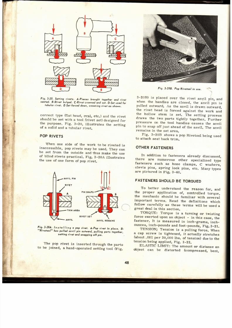
7/26/2019 Auto Service and Repair - Martin W. Stockel
http://slidepdf.com/reader/full/auto-service-and-repair-martin-w-stockel 48/224
tr
?
ri,
,f
:,il
i
l r i
t :
i,'i
l
+ii
$l l
¡
:ti
ll r
ii j
: ,i
'
i.i
l
ii
i .
lt
l
I
t
il i
i
i
l
Fig.
3-20.
Setl ing
rivets.
A-Pieces
brought
togerher
ond
rivet
seofed.
8-Rivet
bulged.
C-River crowned
ond
seJ.
D-Set
used
fo ¡
tubulo¡
¡ ivet,
E-Sef
orced
down,
crowning
ivef
os sñown.
correct
type
(f lat
head,
ov;r ,
etc.)
and
the
rivet
should
be
set
wi th
a tool
(r ivet
set)
designed
fo r
the purpose.
F ig.
3-20,
i l lustrates
the
sett ing
of
a
solid
and
a
tubular
rivet.
POP
RIVETS
When
one
side
of
the
work
to
be
riveted
is
inaccessible,
pop
rivets
may
be
used.
They
ca n
be
set
from
the
outside
and
thus
make
the
use
of blind
rivets
practical.
Fig.
3-20A
illustrates
the
use
of
one
form
of
pop
rivet.
ln
IU
fN
NAps
r
THIN
AREA
nrver
ef
Fig.3-20A,
Instol l ing
d
pop
rive¡.
A_pop
¡ivet
in
ploce.
B-
' lRivetool"
hos
pu|Ied
or"it' pin
our*o,i,'oíU,ri' irr)r"
rlsethet,
sefiing
rivet
and
snopping
off
pin,
The
pop
rivet
is
inserted
through
the parts
to
be
joined,
a hand-operatecl
setting
tool
(Fig.
To
better
understand
the
reason
for,
an d
the
proper
applicat ion
of,
controlled
torque,
the
meehanie
should
be
familiar
with
several
important
terms.
Read
the
definit ions
which
fo11ow
earefully
as
these
terms
will
be
used
a
\.-
r
great
deal
in
this
sect ion.
Fis.
3-208.
pop
Riveroo/
n
use.
., '.1.",
3-208)
is placed
over
the
r ivet
anvi l
p in,
an d
when
the
handles
are
closed,
the
anvil pin
is
pulled
outward.
As
the
anvil
is
drawn
outward,
the rivet head is forced against
the
work
an d
the
hol low
stem
is
set .
The
set t ing
process
draws
the
two parts
t ight ly
together.
Further
pressure
on
the
tool
handles
causes
the
anvil
pin
to
snap
off
just
ahead
of
the
anvil.
The
anvil
remains
in
the
set
area.
Fig.
3-20B
shows
a
pop
Rivetool
being
used
to
at tach
seat
back
t r im.
OTHER
ASTENERS
In addition
to fasteners
already
discussed,
there
are
numerous
other
specialized
type
fasteners such as hose clamps, C washers,
clevis pins,
spring
lock pins,
etc.
Many types
are
pictured
in
Fig.
B-40.
FASTENERS
HOULD
E
TOROUED
-
TORQUE:
Torque
is
a turning
or
twisting
force exerted upon an object - in this case, the
fastener.
It
is
measured
in
inch_grams,
inch_
ounces,
nch-pounds
and
foot_pounds,
F ig.
3_21.
TENSION;
Tension
is
a
pull ing
force.
When
9
""p
screw
is
tightened,
it
actually
stretehes
(about.001
per
90,000
bs.
of tensioó
dueto
the
tension
being
applied,
Fig.
3-22.
ELASTIC
LIMIT:
The
amount
or
disrance
an
object
can
be
distorted
(compressed,
bent,
ANYIL
REMAINS
48
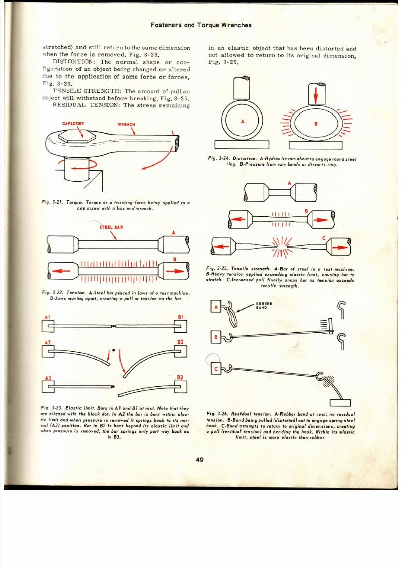
7/26/2019 Auto Service and Repair - Martin W. Stockel
http://slidepdf.com/reader/full/auto-service-and-repair-martin-w-stockel 49/224
Fqsteners
on d
st retched)
and
st i l l returntothe
same dimension
when
the force
is removed,
Fig.
3-23.
DISTORTION:
The
normal
shape
or con-
f igurat ion
of
an object
being
changed
or altered
due
to
the
applicat ion
of some force
or
forces,
Fig.
3-24.
TENSILE
STRENGTH:
The
amount
of
pull
an
object wi l l wi thstand before breaking, Fig. 3-25.
RESIDUAL
TENSION:
The
stress remaining
CAPSCREW
WRENCH
Fig.
3-21,
Torque.
Torque ot o twist ing
lorce being
applied to o
cop screw
with o box
end wrench.
Fig.
3-22.
fension.
A-Sreel 6o¡
ploced
n
iows
ol o
fesf
mocfi ine.
B-Jows
moving oport,
creol¡ng
o
pull
or fension on the bar.
Fig.
3-23.
Elos¡ic L in it .
Bors
n
Al ond
BI o¡
rest.
Nofe
thot
they
te
oligned
with the black
dot. ln
A2
¡he
hor
is
bent within elos-
fic
l¡n¡t
and when
pressure
is
¡emoved t
springs 6ock to its no¡-
ml
(43)
positíon.
Bo¡
in
82
is bent
beyond ts
elosfic
limi¡ ond
rlren pressure
ís removed,
the
bor springs only
part
woy
6ock os
in
83 .
Torque
Wrenches
in
an
elast ic object
that
not
allowed
to return
to
Fig.
3-26.
has
been
distor ted
and
its
original
dimension,
Fig.
3-24.
Dis.tort ion.
A-Hydroulic om
oboul o
engoge
ound
steel
r ing.
B-Pressu¡e rom
¡am óends
o¡ distorts
r ing.
B2
\4
Y83
4
\\IZ
7/t1r-
Fig.3-25.
Tensile
strength.
A-Bsr ol
steel in o test
mocñine.
B-Heovy tension
opplied
exceeding
elostic l imit,
covsing bor to
sf¡elch.
C-lnc¡eosed
pull
{inolly
snops óor
os fensjon
exceeds
tensile
strength.
\^z*n¡ -
Fig.3-26.
Resíduol
tension.
A-Ru66er band ot Íest, no residuol
lension.
B-Bond
being
pulled
(distorted)
out
o
engagespring
sfeel
fiook.
C-8ond
ottempls
to rcturn to
originol dimensions,
creating
o
pull
(residuol
tension)
ond bending
the hook.
Ylithin
its
elostic
limit,
steel is more
elosfic than ¡ubber,
O
\ r r r ro*
i l l t r /
49
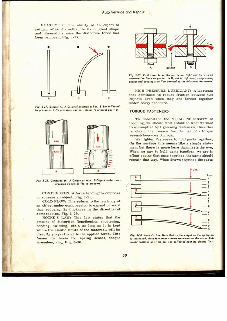
7/26/2019 Auto Service and Repair - Martin W. Stockel
http://slidepdf.com/reader/full/auto-service-and-repair-martin-w-stockel 50/224
Auto
Service
ond
RePoir
ELASTICITY:
The abil i ty of
an object
to
return,
after
distortion,
to
its
original
shape
and
dimensions once
the distort ive
force has
been removed,
Fig.
3-27.
Fig. 3-27. Elasticity. A-Originol position o{ ho¡. B-Bor deÍlected
by
pressure,
C-No
pressure,
and
ba¡ ¡eturns to
original
posifion.
Fig.3-28, Compression.
A-Obiect
ot
rest.
8-Object
under
com-
pression
as ¡am builds
uP
ptessure.
COMPRESSION:
A force
tending to compress
or squeeze an
object,
Fig.
3-28.
COLD
FLOW: This refers
to the
tendency
of
an object under compression
to expand
outward
thus reducing
its thickness
in the direction
of
compression, F ig. 3-29.
HOOKE S LAW:
This
law
states
that
the
amount of
distortion
(lengthening,
shortening,
bending,
twisting,
etc.),
as long
as
it is
kept
within
the elastic
limits of
the
material,
will be
directly
proportional
to the
applied
force.
This
forms
the basis
for spring
scales
torque
wrenches,
etc. ,
F ig. 3-30.
B
Fig.3-29. Cold
{low. ln
A,
the nul is nof
tight
ond
fáe¡e
is no
compressíve
lo¡ce on
gos/<el.
ln
B, nut is
tightened, compressing
goskef
ond cousing
il to llow oulwo¡d
os
tlre thickness dec¡eoses.
HIGH PRESSURE
LUBRICANT: A
lubricant
that continues
to reduce
friction
between
two
objects even
when they
are
forced together
under
heavy
pressure.
TOROUE ASTENERS
To
understand the
VITAL
NECESSITY
of
torquing,
we should
first
establish
what we want
to accomplish
by
tightening
fasteners. O¡rcethis
is clear, the reason
for
the use
of
a
torque
wrench become s obvious.
We t ighten
fasteners
to
hold
parts
together.
On
the surface
this
seems like a
simple state-
ment but there is more here than
meets
the
eye.
When
we
say to hold
parts
together,
we
are
in
effect
saying that once together, the
parts
should
remain
that way.
When drawn
together the
parts
-0
-2
-0
_l
2
3
Fig. 3-30.
Hooke s
low. Nofe fñot os fÁe
weight on
the spring
bo r
is increosed,
táe¡e ís o
ptoportionole
movemenl
on tfte scole.
T]rís
would conlinue
until the
bor wos dellec¡ed
Posl
its eloslic
limit.
- l
-l
- t
0 Lbs.
Lbs.
0
I
2
3
50
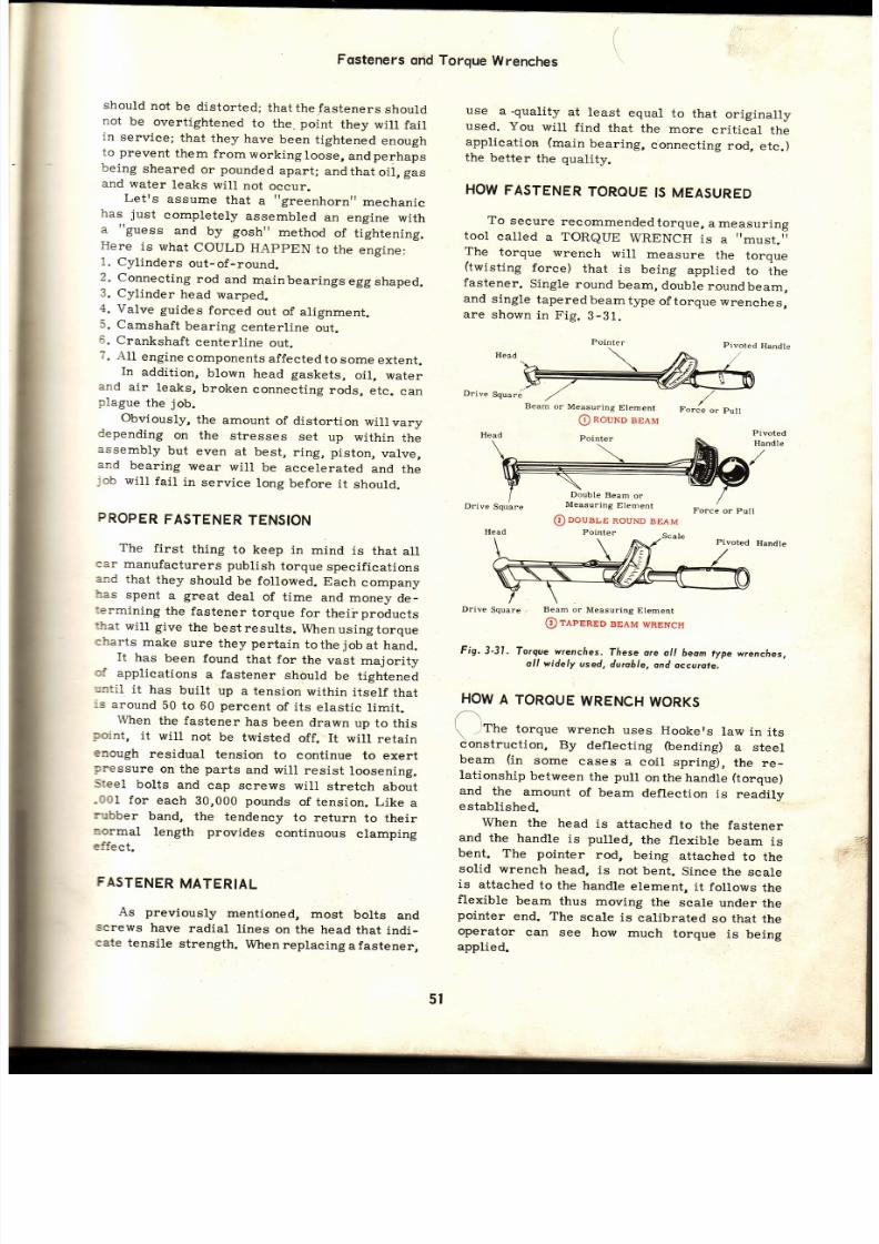
7/26/2019 Auto Service and Repair - Martin W. Stockel
http://slidepdf.com/reader/full/auto-service-and-repair-martin-w-stockel 51/224
Fqsteners
qnd
should
not
be
distorted;
that
the fasteners
should
not
be
overtightened
to
the. point
they
wil l
fai l
in
service;
that
they
have
been
tightened
enough
to prevent
them
fromworkingloose,
andperhaps
being
sheared
or
pounded
apart;
andthatoil,gas
and
water
leaks
wil l
not
occur.
Letts
assume
that
a
t'greenhornrt
mechanic
has
just
completeJ.y
assembled
an
engine
with
a
guess
and
by
goshrr
method
of
tightening.
Here
is
what
COULD
HAppEN
to
the
engine:
1.
Cylinders
out-of-round.
2.
Connecting
rod
and
mainbearings
egg
shaped.
3.
Cylinder
head
warped.
4.
Valve
guides
forced
out
of
alignment.
5.
Camshaft
bearing
centerl ine
out.
6.
Crankshaft
centerl ine
out.
7.
All
engine
components
affected
to
some
extent.
In
addition,
blown
head gaskets,
oil, water
and
air
leaks,
broken
connecting
rods,
etc .
ca n
plague
the
job.
Obviously, the
amount
of distortion
wil lvary
depending
on
the
stresses
set
up
within
th e
assembly
but
even
at
best,
r ing,
piston,
valve,
and
bearing
wear
wil l
be
accelerated
and
th e
job
wil l
fa i l
in
service
long
before
it
should.
FROPER
FASTENER
TENSION
The
first
thing
to
keep
in
mind
is
that
al l
car
manufaeturers
publish
torque
specif ications
and
that
they
should
be
followed.
Each
company
bas
spent
a
great
deal
of
t ime
and money
de-
:ermining
the
fastener
torque
for
theirproducts
'}rat wil l give the bestresults.
Whenusingrorque
eharts
make
sure
they pertain
tothe
jobat
hand.
It
has
been
found
that for
the
vast
majority
cf
applications
a
fastener
should
be
tightened
-¡¡til
it
has
built
up
a tension
within
itself
that
:s
around
50
to 60
percent
of its
elastic
limit.
When
the
fastener
has
been
drawn
up to
this
roint,
it
will
not
be
twisted
off.
It will
retain
enough
residual
tension
to
continue
to exert
sressure
on the
parts
and will
resist
loosening.
Steel
bolts
and
eap screws
will
stretch
about
.001 for
each
30,000
pounds
of tension. Like
a
rubber
band,
the tendency
to return
to their
normal length provides continuous clamping
effect.
FASTENER
ATERIAL
As
previously
mentioned,
most
bolts
an d
screws
have
radial
t ines
on the
head
that
indi-
cate
tensil.e
strength.
Whenreplaeing
afastener,
Torque
Wrenches
use
a.quality
at least
equal
to
that
originally
used.
You
wil l
f ind
that
the
more
critical
th e
application
(main
bearing,
connecting
rod,
etc.)
the
better
the
quality.
HOW
FASTENER
TOROUE
S MEASURED
To
secure
recommended
torque,
a measuring
tool
called
a TOReUE
WRENCH
is
a
must.
The
torque
wrench
wil l
measure
the
toroue
(twisting
force)
that
is
bei.ng
applied
to
ih e
fastener.
Singte
round
beam,
double
roundbeam,
and
single
taperedbeamtype
oftorque
wrenches,
are
shown
in Fíg.
3-31.
Handle
Drive
Squaró
Head
Beam
or
Measuring
Element
@
Rouwoeeeu
Pointer
Pivoted
Handle
Double
Beam
or
Measuring
Element
@
nouale
RouND
BEAM
Pointer
Force
or
Pull
Drive
Square
, Beam
or
Measuring
Element
@ reenaeo BEAM wRENcH
Fig,3-31.
forgue wrencfies.
ñese ore
ol l beom
ype
wrenches,
oll widely
used,
durcble,
ond
occurote.
HOW
A
TOROUE
WRENCH
WORKS
\
l ttr
torque
wrench
uses
Hookers
law in
it s
c\onstruction,
By
deflecting
(bending)
a
steel
beam
(in
some
cases
a
eoil spring),
the re-
lationship
between
the
puLl
onthe
handle
(torque)
and
the
amount
of beam
deflection
is readilv
e
stablished
When
the
head
is
attached
to the fastener
and
the handle
is pulled,
the flexible
beam
is
bent.
The pointer
rod,
being
attached
to the
solid
wrench
head,
is
not
bent.
Since
the
scale
is
attached
to
the handle
element,
it follows
the
flexible
beam
thus
moving
the
scale
under
the
pointer
end. The
scale
is
calibrated
so that
the
operator
can see
how
much
torque
is
being
applied.
5l
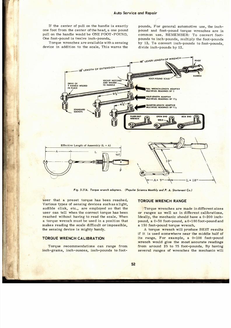
7/26/2019 Auto Service and Repair - Martin W. Stockel
http://slidepdf.com/reader/full/auto-service-and-repair-martin-w-stockel 52/224
AutoService
ond
Repoir
i]
l
I f
the
center of
pull
on
the handle
is exactly
one
foot from
the
center ofthe
head,
a one
pound
pul1
on the
handle would
be
ONE
FOOT-POUND.
One foot-pound is
twelve inch-pounds.
Torque
wrenches
are available
witha
sensing
device
in
addition to
the sca1e.
This warns
the
\rser that
a
preset
torque has been reached.
Various t¡pes
of sensing devices suchas alight,
audible click,
etc., are employed so
that
the
user can
tell when
the correct torque has been
reached
without
having to read the scale.
\4¡hen
a torque wrench must be used in a posit ion that
makes
reading the
scale
difficult
or
impossible,
the sensing
device is mighty handy.
TOROUE
WRENCH
AL BRATION
Torque recommendations
can
range
from
inch-grams, ineh-ounces,
inch-pounds to
foot-
pounds.
For general
automotive
use, the inch-
pound
and foot-pound
torque wrenches
are in
common use. REMEMBER:
To
convert foot-
pounds
to inch-pounds,
multiply
the foot-pounds
by
12.
To
convert inch-pounds
to foot-pounds,
divide inch-pounds
by
12.
FOOI.POUND
SCAIE
FUTTWRENCH.I,:NGTH
ADAP ER
,\AULIIPTIES
EADINGS
3Y 2
HAI.F-I.CNGTH
ADAPTEP
MutilPuEs
nEAD|NGS
8y lt,/2
OUATTE¡.TTNGfH ADAPTER
IiUI.TIPTIES
¡EADINGS BY I ¿
SIANOARD
50cKEf5
OPEN END
,a\
gOX
END
IYCID
\ -a=
L=
t8,t
Fig. 3-314. Torque wrench odoplers,
(Populor
Science Monthly ond P.
A. Sfurfevonr
Co.)
\
\
J .
;l
t
.
1
TOROUE
WRENCH ANGE
. Torque
wrenches
are
made indifferentsizes
or ranges
as
well
as in different
calibrations.
Ideally,
the mechanie
should
have
a 0-200 inch-
pound, a 0-50 foot-pound, a0-100 foot-poundand
a 150
foot-pound
torque
wrench.
A torque wrench will
produce
BEST
results
if it is
used somewhere near the middle half
of
its range. For
example, a
0-100
foot-pound
.wrench
would
give
the most aecurate readings
from around 25
to
?5 foot-pounds.
By
having
several ranges of
wrenches
the
meehanie wil l
Effective
Lengfh of Assembly
(L
+
A)
52

7/26/2019 Auto Service and Repair - Martin W. Stockel
http://slidepdf.com/reader/full/auto-service-and-repair-martin-w-stockel 53/224
Fqsteners ond
Torque
Wrenches
also
find that
this
will
offerhimseverallengths.
The
shorter ones
can
be useful in restricted
quarters.
RANGE
ANBE
ALTERED
BY
USING
N ADAPTER
Say you have a 0-100 foot-pound wrench
available and the torque
recommendation
is
150
foot-pounds. This
is
obviously
beyond the
range
of the
wrench. It
ean
stil lbe used
however
through
the use of
an adapter
to lengthen the
effective range.
If
the lever lenlth
(distance
from the
center
of wrench head
to
pivot point
on the
handle) is
19 in. and
you
used an adapter
bar
of equal
length,
the torque being
applied
would be double
that
shown onthe seale.
f
the everwas
9-1/2 in.
or half
as
long
as the lever length, the
torque
would
be
one
and
one-half
times that
shown
on
the scale. A handy formula to
determine applied
torque
when using
an adapter or extension
is
as
follows:
and
to
the
area
where
the nut orcap serew head
contacts
the
part..
Never-seez,
Fel -Pro
C-5,
Molykote
or a
similar high
strength lubricant is suitable.
The
use of this lubricant
will
prevent
or re-
duce the
possibil ity
of
gall ing,
seizing
(sticking)
or
stripping, and
will
assure that the
fastener
torque has created the proper tension. It should
be mentioned
that the lubricant,
while making
the
fasteners
easier
to
remove at some
future
date,
wil l
not
(if
torqued
properly)
cause them to
loosen i.n
service.
Tothe
contrary, the
increased
tensioning for
the same torque reading
will
actually
cause
the fastener to remain more
secure.
USE
PROPER
OCKING
EVICE
Unless a self-Iocking nut or
cap
screw
is
being used, make
certai.n
the recommendedlock
washer is in
place.
When
running a fastener up
against the softer metals, the use
of
a
plain,
flat washer
between
the Lockwasher andthe
part,
i .s often
specif ied.
This
prevents
the
part
from
being
"chewed'r
up and allows
proper"torquing
without
crushing
the
part.
CHECKFASTENERS
Be
careful
to
check
fasteners for
correct
diameter,
threads
per
inch and length.
When
install ing
cap
screws,
make
certain
they will
not bottom
(strike
bottom of a threaded
hole),
in a blind
hol.e
hole
not drilled
clear
through
part),
nor in a through
hole
protrude
into the
housing and
damage
a
part
of the unit.
REMEMBER:
Str ipped
threads, broken
screws,
loose
parts
and damaged units can
re -
sult.
Be
carefuli
In
A,
F ig. 3-32, the screwhasbot tomedleav-
S¡.
ing the
part
loose. Continuedtorquing could
twist
off the screw.
In B, the screw
protruded
into
case and
damaged
gear.
In C,
coarse
thread
screw,
jammed
into hole with f ine
threads,
cracked
part, Fig.
3-32.
If
any
fasteners serve
an addit ionalpurpose,
such as a
head bolt or cap
screu/ that
may be
dril led for
passage
of
oil, or
a
cap
screw
with
Dial
reading x
(L
+
A)
L
--t -
=
Torque
applied to
fastener'
(L)
(A)
Fig.
3-31A, shows
three adapter setups.
Notice
that the effective length
(L+A)
is always
measured
parallel
to the centerline
of the
wrench.
REMEMBER:
When
using
adapters
or
extensions, be certain of their exact length. Do
no\
forget
that length and torque are direc tly
r3, l rdted, ig .3-31A.
USING
OROUEWRENCH
After determining the
proper
torque and
selecting a suitable range torque
wrench,
yo u
are ready to
proceed.
Be
sure
to
observe
th e
following:
THREADS MUST BE
CLEAN:
The threads on
the boLt
or screw
as
well
as
those in the nut or
hole, must be
absolutely clean.
Rust,
carbon,
dirt, etc.,
wil l
cause
gall ing
and
improper ten-
sion. An accurate torque reading
with dirty
threads
is
impossible.
USE HIGH TEMPERATURE
LUBRICANT:
Unless the
use of a lubricant
is specif icallyfor-
bidden
(due
to
the
possibility
of area contami-
nation
or
the need of
a special
sealant) always
apply
a
high
pressure
Iubricant to the
threads
rs
¡^
ID
be
the length
j.n
nches from
the center
of the handle
pivot
to
the center of the wrench head.
the
length in
inches from the
center
of the wrench head
to the end of the
adapter.
Must
measured
parallel
to the centerline of
the
wrench.
53

7/26/2019 Auto Service and Repair - Martin W. Stockel
http://slidepdf.com/reader/full/auto-service-and-repair-martin-w-stockel 54/224
Auto
Service
ond Repoir
I
¡S
Fig.3-32.
Check fosteners/
Moke certoin
thot fosteners
o¡e of
lhe
correcl
diometer, length
ond with
sul l icient
th¡eod
ol tfre
co¡-
rect number
o{ tee¡h
oe¡ inch.
a threaded
hole
in
the
head to
which
another
assembly
is
attached,
be
careful to inser t
them
in the
correct
place.
FOLLOW
RECOMMENDED
EOUENCE
Where a
number
of
fasteners
are used
to
secure
a
part
(such
as a
cy l lnder
head)
the
proper
sequence
(order)
of
t ightening
shouldbe fo l lowed.
tr ig.
3-33
i l lustrates
the head
bolt
t ightening
sequence
for
one
model
engine.
Always
fol low
the manufaCturerSr
gnenif ior i innq
eoe nig.
3_33.
FRONT
Fig,3-33.
Cylinderheod
bolt tightening
eguence.
(American
Mofo¡s)
I f
no
sequence
chart
can
be
obtained,
i t is
usually
advisable to start in the center and work
out
tothe
ends. The
chart inFig.
3-34,
i l lustrates
this
technique.
On
some
assembl ies,
i t is
advisable
ro
use
a
cr isscross
sequence.
Always
avoid s tar t ing
in
one spot
and
tightening
one
after
another in
a
row. Remember
that
the
object
is
to tighten the
parts
in
such
a manner
that
an
even stress is
' t . .
\ ' . -
_
-
--
1r '
, r '
a
t.
----- . -
-_
<--/
uu
/
:
t-
,a , /
\.
-
<---
"'
Fig. 3-34.
Heod
bolt
t ightening
seguence
when
no
speciol recom-
mendotion
is ovoi loóle.
(Victor
Gosker
Co.)
set
up
throughout,
at
the
same
time,
allowing
the
parts
to
be
drawn
together
so
that their
mating
sur faces
wi l l
contact, Fig.
3-35.
Fig.
3-35.
Tightening
bol ts in..írr .r ls
sequence.
Fig. 3-36.
frong
eguence
n tighlening
osleners.
his seguence
wouldproduce
very poor
it
Would a good fi t be acquired if you followed
the
sequence
shown
in Fig.
3-36?
Quite
obviously
if this
sequence
is followed,
the
two
ends would
be
clamped down
first
an d
when
the
center bolts
were
tightened
the
part
could
not flatten
out.
In
order
to
flatten,
it must
spread
outward
and in
order
to do
this,
the ends
must
be
free.
o@o@oc
@@o
@oooilo
oo@o@o
@__@_@
ooo@o@
54
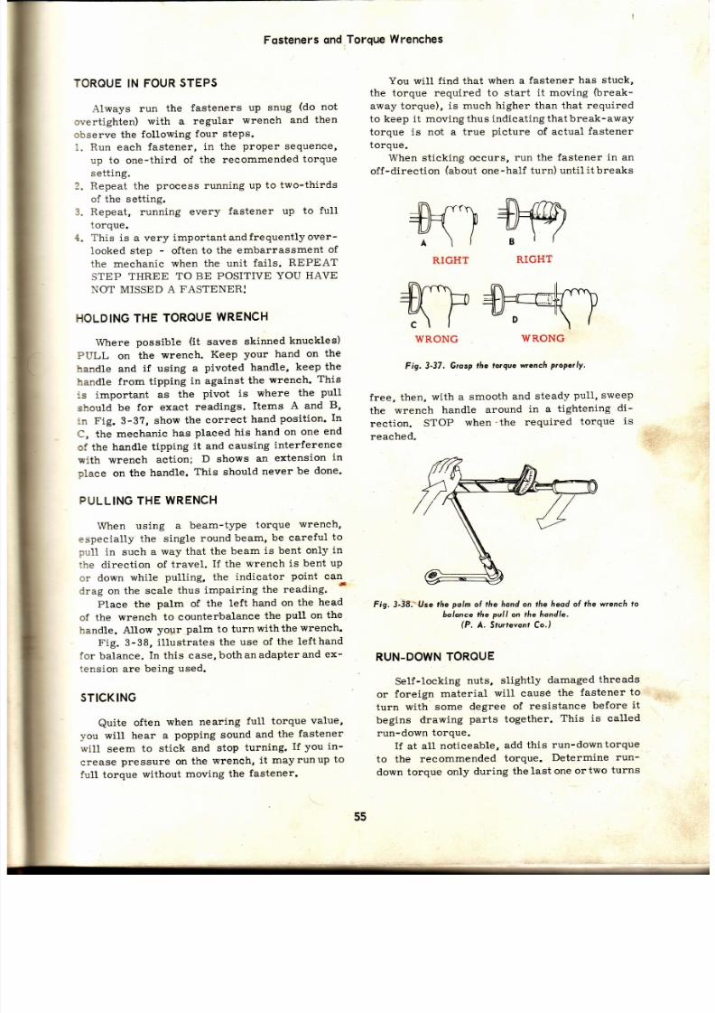
7/26/2019 Auto Service and Repair - Martin W. Stockel
http://slidepdf.com/reader/full/auto-service-and-repair-martin-w-stockel 55/224
Fqsteners
nd
Torque
Wrenches
TOROUE
IN FOUR
STEPS
Always run
the
fasteners
up
snug
(do
not
overtighten)
with a
regular
wrench
and
then
abserve the
following
four steps.
i.
Run
each
fastener,
in the
proper
sequence,
up
to
one-third
of
the recommended
torque
setting.
.
Repeat the
process
running
up to
two-thirds
of the setting.
3.
Repeat,
running
every
fastener
up
to full
torque.
4. This
is a very
importantandfrequentlyover-
looked step
-
often
to the
embarrassment
of
the meehanic
when the unit
fails.
REPEAT
STEP
THREE
TO BE
POSITIVE
YOU
HAVE
NOT MISSED A
FASTENER:
HOLDING HE
TOROUE
WRENCH
Where possible (it saves skinned knuckles)
PULL
on
the
wrench.
Keep
your hand on
the
handle and
if using
a
pivoted handle,
keep
the
handle
from tipping
in against
the
wrench.
This
:s
important
as
the
pivot
is
where
the
pull
should
be
for
exact
readings.
Items
A
and
B,
:n
Fig. 3-3?,
show
the
correct
hand
posit ion.
In
C, the
mechanic
has
placed his
hand
on
one
en d
of the
handle
tipping
it
and
causing
interference
sith wrench
action;
D shows
an
extension
in
place
on the
handle.
This
should
never
be done'
PULLING
THE
WRENCH
When using
a beam-type
torque
wreneh,
especially
the single
round
beam,
be careful
to
-¡u11
n such
a
way that
the beam
is bent
only
in
:he direction
of
travel.
If
the
wrench
is
bent up
or down
while
pulling, the
indicator
point
can
drag on
the scale
thus
impairing
the
reading.
*
Plaee the
palm
of
the left
hand
on
the
head
of the
wrench
to counterbalance
the
pull
on
the
handle. Allow
yolrr
palm to
turnwiththewrench.
Fig. 3-38,
il lustrates
the use of
the
lefthand
for
balance.
In this case,bothanadapterand
ex-
tension
are
being
used.
STICKING
Quite
often
when
nearing
full
torque
value,
you
will
hear a
popping
sound
and
the
fastener
will
seem
to stick
and
stop
turning.
If you
in-
crease
pressure on
the
wrench,
it
mayrunup
to
full torque
without
moving
the
fastener.
You witt
f ind
that
when a
fastener
has stuck,
the torque requir ed to start
lt moving
fureak-
away torque),
is much
higher than that required
to keep it moving
thus
indicating
that
break-away
torque is not a
true
picture
of actual
fastener
torque.
When sticking
occurs,
run the fastener
in an
off-direction (about one-half turn) until i t breaks
Fig.3-37.
Grosp
táe lorque wrench
properly.
free,
then,
with a
smooth
and
steady
pull,
sweep
the
wrench
handle
around
in a
tightening
di -
rect ion.
STOP
when' the
requi red
torque
is
reached.
Fig. 3-38.-'Use
the
polm
ol the
hond on the heod ol
the
wrench
to
bolonce
the
pull
on
the hondle.
(P.
A. Srurrevonr Co.)
RUN-DOWN
OROUE
Self-locking
nuts,
slightly
damaged
threads
or
foreign
material
wil l cause
the
fastener
to
turn
with
some
degree
of
resistance
before
it
begins
drawing
parts together.
This
is called
run-down
torque.
If at all
noticeable,
add
this
run-downtorque
to the
recommended
torque.
Determine
run-
down
torque only
during
the last
one
or
two
turns
[n\ rflva,
tf+ur7
; \ (
RIGHT
S)*=dtr.)
D
' \
|
WRONG
n\ rrrn
+)F1
p
te\ l
Al l
RIGHT
: \ l
WRONG
55

7/26/2019 Auto Service and Repair - Martin W. Stockel
http://slidepdf.com/reader/full/auto-service-and-repair-martin-w-stockel 56/224
Auto
Service
ond Repoir
of
the
fastener.
When
a
fastener
is f irst
started,
it
may
show
considerable
resistance
but
by
th e
time
it
reaches
bottom,
this
may
have
Iessened
or
disappeared.
CAUTION:
Whenever
a fastener
shows
undue
resistance
-
remove
it
and
make
sure
it
is
th e
right
length,
diameter,
and
has
the proper
num_
ber of threads per inch.
WHEN
TOROUE
ECOMMENDATTONS
ARE
NOT
AVAILABLE
The
mechanic
should
make
every
endeavor
to
secure
the
car
manufacturerrs
recommended
torque
for
the
specif ic
job.
I f , however,
it is
no t
available
it
is
wise
to
consult
a
chart
such
as
the
one in
Fig.
3-3g,
to
determíne
the
tensile
strength
of the
fasteners
being
used.
you
will
note
that
by
using
the
head
markings
and
diam_
eter,
an
approximate
torque
sett ing
may
be
de _
termined.
Keep
in
mind
that
if
the
fastener
is
threaded
into
aluminum,
brass
or
thin
metal,
the
torque
figures
rnay
have
to
be
reduced
to prevent
str ipping,
Figs.
SA
and
3-S9.
BOIT
TOROUE
-t
RETOROUING
On
some
assembl ies,
suchas
cyl inderheads,
manifolds,
etó.,
all fasteners
should
be
torqued
after
a
certain
period
of
operat ion.
Cases
such
as
these,
and
the proper,
interval,
wil l
be
dis_
cussed in the sect ions ' 'cover ing units to which
they
apply.
SUMMARY
The
expert
mechanic
is
vitally
concerned
with
fastener
design,
applieat ion
and
torque.
He
real izes
that
to
a great
extent ,
the
suecess
or
failure
of his
work
depends
upon
the proper
us e
of fasteners.
There
are
many
types
of fasteners;
screws
that
thread
into
a
part,
bolts
that
pass
through
the parts
and
require
nuts,
studs
that
thread
into
the part
and also use a nut, and sheet metal
scréws
that
cut
their
own
threads.
The
Unif ied
National
Coarse
and
the
Unif ied
Nat ional
Fine
thread
ser ies
are
commonlyused.
Threaded
fasteners
are
identif ied
by
material,
thread
pitch,
diameter,
length
of
t trread,
type,
etc.
Steel
bolts
and
screws
use
radial
markings
on
the
head
to
indicate
material
and
tensile
strength.
The
removal
of
broken
fasteners
can
cause
dif f iculty
unless
done properly.
Various
methods
are
used.
When threads
in
a hole
are
damaged
beyond
repair,
the
hole
may
be
drilled
and
tappedf----=)
1. To the next suitable
oversize
r,á-
,
nyg),
cap
screw
installed.
2.
To accept
a
threaded
plug.
3.
To
accept
a
patented
coil
wire
inserr.
-.Srap
rings,
rivets,
clevis
pins,
keys
an d
splines
are
nonthreaded
fasteners.
Fasteners
tend
to
loosen
in
service.
Self_
locking
nuts,
various
lock
washers,
safetywire,
locking
plates
and
cotter
pins
are
some
of
the
most
used
methods.
of keeping
fasteners
t ight.
Fastener.
tension
is
important
to prevent
distort ion,
to
keep
fasteneis
t ight
and
to
pre_
vent
fastener
faifure.
To
provide
proper
ten_
sion, fasteners should be torqued.
Several types
of
torque
wrenches
are
avail_
abie
for
this
purpose.
They
mr,rst
be
used
prcgierly.
Use high
pressure
lubricant
on the
threads
and
under
the
head
or
under
the
nut
area
on
fasteners.
Be
certain
the
fastener
is
of
th e
correct
length,
diameter
and
has
the
proper
number
of threads
per
inch.
'
, i . : .
'..*t$,s,
Size
FL
Lbs.
Ll4-28
95 n.
Lbs.
5/16-18
00
n.
Lbs.
5116-24
20
3/8-16
30
318-24 35
7lI6-t4
50
7116-20
55
U2-13
75
Ll2-20
85
9ll6-t2
105
9/16-18
115
5/8-11
150
5/8-18
160
314-16
175
10.733575
22.597
27.tL64
40.6745
47.4536
67.7%9
74.5700
101.6864
tL5.2441
142.3611
i55.9191
203.373
216.931
237.268I
270 n.
Lbs.
25
4045
65
70
100
110
135
150
195
2t0
225
16.947750
31.207950
33.8955
54.232761.0118
88.12E2
94.9073
135.582
t49.L40
183.0351
203.373
2U.3841
284.722
305.0591
neurton
metres
Ft Lbs.
150
n.
Lbs.
newton
metres
sAE
CIASSI
IC A
GRADE
5
GRADE
MARKINGS
FOUND
ON TOP
OF
BOIT
HEAD
INDICAÍE
GRADE
Fig.3-39.
(fiort
sfrows
torque
volues
lo¡
Grode S ond
Grode
g
fosfeners.
Jee_pig.
3-A
. Ío r
oddit iorol
, .oJing .
lDodse)
56

7/26/2019 Auto Service and Repair - Martin W. Stockel
http://slidepdf.com/reader/full/auto-service-and-repair-martin-w-stockel 57/224
Fosteners
ond
Torque
Wrenches
,
The
proper sequence
of
t ightening
is very
:mportant.
Always
follow
the
manufacturerrs
:ecommended
torque
and sequenee.
SUGGESTED
CTIVITIES
i
Take a sheet of paper, wad it intoa bal1, pull
it back
out
and
lay
it onthe
table.
If
you
were
to
try' to
press
it out
flat,
where
would
yo u
place
your
hands
(fastener)
first.
In
what
direction
(sequence)
would
you
move
them'
Try it.
How
does
this
compare
to
tightening
sequence.
Using
a
regular
wrench,
turn
up
severar
3/8
in. screws
to
what
you
would
guess
to be
15
foot-pounds
of
torque.
Take
a
torque
wrench and
break
themloose.
Watchthe
scale
carefully
to
determine
the
toique
requiredto
start
them.
Even though
this
will
be
differ-
ent than true torque, how even were they?
Was i t
c lose
to
15
foot-Pounds?
3.
Place two
1
4
in.
bolts,
(one
with
six
radial
lines
on
the
head
and
the
other
with
none)
of
equal
length
in
a vise.
Keep
them
about
tw o
inches
apart
and
with
the
same
amount
of
material
in the
jaws.
Run
the
vise
up
tightly'
With
a suitable
torque
wrench,
turn
eachbolt
untit
it
snaps.
Watch
the
scale
earefully
to
determine
torque
at-the
moment
of
failure'
Was
the
reading
fihe ]ame?
If
not,
why?
Yo u
wiII
also
note
that\doesnottake
much
effort
to snap
a
1/4
in.
bol t .
WOULD
OU
USEA TOROUE RENCH?
Let 's
suppose
you are
tobe
carr ied
alof t
20
stories
on
a
small
steel
platform.
The
platform
is attached
to
the
cable
with
ONE
bolt '
This
bolt
MUST
be
torqued
to
150
FOOT-POUNDS'
-\ t
160
foot-pounds
it
wil l
break
in mid-air
an d
at
140
foot-pounds
i. t
wil l
sl ip.
Anybody
for
a
torque
wrench?????
ñeMpt\tenR:
YouR
REPUTATIoN
AS
A
MECHANIC
CAN
WELL
BE 20
STORIES
OF F
THE
GROUND.
KEEP
IT SAFE.
FOLLOW
RECOMMENDED
TORQUE
ANDUSE
ATORQUE
WRENCH:
OUIZ
-
ChoPter
1.
Screws
require
the
use
of .nuts '
True
or
False
?
2. Sheet
metal
screws
should
be
threaded
into
a
hole
about
the
size
of
their
major
diam-
eter.
True or
False?
3.
Dr i l l ing
is considered
super ior
to
punching
holes
in
which
sheet
metal
screws
are
to
be
inserted.
True or
False?
4.
A stud
has-on
-ends.
5. Studs
are
beét
instal led
with
pl iers.
True
or
False
?
6.
Name
four
methods
that
may
be
used
to re-
move
broken
screws
or
studs.
?.
How can
a st r ipped
hole
be
repaired?
Two
methods.
B.
Three
radial
l ines
on
the
headofabolt
indi-
cate
that
it
has
greater
tensile
strength
than
a
bolt
with
six
radial
l ines.
True or
False
?
9.
Define
the
term
major
diámeter.
10.
How can
the
number
of
threads
per
inch on
a
screw
be
determined?
11.
Def ine
the
term
minor
diameter .
12.
Name
the
two
popular
thread
ser ies.
13.
When
referr ing
to thread
class,
a
2A
would
apply to a threaded nut with a fair ly accu-
rate
f it .
True or
False
?
14.
The
class
2
f i t
is-usedforautomobi le
fasteners.
15.
Descr ibe
two
kinds
of
sel f - locking
nuts '
16.
Name
the
three
basic
types
of lockwashers '
1?.
To use
the
palnut, run
i t
down
to
the
nut,
open
side
away,
and
then
give it
18.
All
fasteners
have
threads.
True
or
False?
19.
A spline.
and
a
woodruff
key
bÓth
act
as
a
driving
mechanism
or
device.
True or
False
?
20. What is a lock Plate?
21.
Snap
rings
should
NEVER
be
reused'
True
or
False
?
:'
22.
A
setscrew
usually
has
a
hexagonal
head'
True
or
False
?
23.
When
a
rivet
is used,
the
rivet
in
the
hole,
the
Parts
must
should
be
24.
25.
-together
and
a--
-should
be
used.
Torque
and
tension
are
one
and
the
same'
True
or
False?
.,r: ':
Define
the
followirig:
1.
Elast ic
Limit.
2'
Dis-
tort ion.
3.
Tensile
Strength.
4.
Torque'
5. Tension. 6. Residual Tension.
7.
Com-
pression.
8. .
Elast ic i ty .
9-
Hookers
L
aw'
10.
High
Pressure
Lubricant.
List
three
reasons
for
proper
fastener
tension.
Proper
tension
is best,achieved
bY
using
a
to
tighten
fasteü ers.
26.
27.
28.
90
Why
use
lubricant
on
fastener
threads?
Torquing
should
be
in
three
init ial
steps'
57

7/26/2019 Auto Service and Repair - Martin W. Stockel
http://slidepdf.com/reader/full/auto-service-and-repair-martin-w-stockel 58/224
AutoService
ond
Repoir
Fasteners
drawn up to_of
reeommended
torque then to-and finally
to-torque.
30.
What
is the important fourth
step
in torquing
?
31.
Indicate your
choice
of the following
range
torque wrenches
that
you
would
use totighten
a bolt to 50 foot-pounds.
1. 0-200 inch-
pound,
0-50 foot-pound,
0-100
foot-pound.
32. What effect will an adapter have on atorque
wrench
reading?
33.
Describe
how sticking during the final
torquing
should be handled.
,.-)
34.
To
allow
the
user to torque fasteners
when
the
position
makes
seeing the scale im-
possible,
a_device is
used.
35. Always
PUSH
a torque wrench.
True
or
False
?
36.
Once
fasteners
have
been
properly
torqued,
they wil l
never need
to be torqued
again.
True or False ?
37. What
is a torque
chart?
38. Torque, for
automotive use, is
measured in
and
in
@
4"
@^
-H
@
N
@
Fig.340.
An
osso¡tment of
losfene¡s.
llthough
terminology con
vory
somewñof, tfiese ore commonly
used
descripfívé nomesi
l-F langeJock
nut.
2-Fil l isrer
heod machine sc¡ew.
3-Borrel
prong
nut.
4-
lling nut. 5-Cop sc¡ew. 6-Pol nut. 7-Co¡¡ioge bol¡. &-Sp¡ing nut. 9-12-point heod bol¡. l?-Round
heod
mochine
screw. l l-Ask¿w-heod
bol¡. l2-Single thread nut.
I3-Flonged nut. l4-Cap screw,
15 -
Ancho¡
nut. l6-Ploin fiex
nuf. l7-Hex
flange
screw. l8-Acorn
(cop)
nut.
I9-Flo¡ heod screw.
20 -
Small
l lat lreod screw. 2l-Speed
nut.22-Sheet
melol
screw. 23-Locking nut.24-Key.2í-Ollset
(ec.
centric) stud. 26-Thin
nut. 27-Cotte¡
pin.
28-$ocke¡ head bolt. 29-Locking nut.
30-lling nut.
3l -
Speciolry
nut.
32-Toothed
/ock wosñe¡s.
33-Thunbscrew.. 34-Stud. 35-Snop
ringi
36-gpring
lock
pin.
37-Cross
heod
mochine screw.38-Ponel
nut.
39-Flonged
hex slotted freod screw.
4O-gp/it
loc/<
wosfier.
4 l-Hex
socket f ieod bolt.
42-l le lded
nut.
43-Plow
bol¡.
44-Clevis
pin.
4s-Open
top ocom nut.
46 -
Closed
rop
ocorn nut.
47-Squa¡e
fieod cop screw.
48-WoodruÍ(
key.
49-Sell+opping
screw,
50-Serrored
nut.5 l-Siotted
nut.
52-Sef
screw.
53-Costle
nut.
54-Flof
woshe¡.
55-Coir le
nur.
tl
j t i
i
:i
1r
1,:
I
I
f
i r
¡l
1:i t
{iiii
'l
l,
i'
I
1r l ,
r:¡
:
i
I
li
58

7/26/2019 Auto Service and Repair - Martin W. Stockel
http://slidepdf.com/reader/full/auto-service-and-repair-martin-w-stockel 59/224
Chapter
4
GASKETS,
EALANTS,
IMPORTANT
ND
WIDELY
USED
Gaskets
and
seals
are
used
throughout
the
car.
They
confine
gas,
oil,
water
and
other
Íluids, in addition
to
air and
vacuum,
to specific
:mits or
areas.
They exclude
the
entry
of
dust,
dirt, water
and
other
foreign
materials
into
rarious parts and they play an important part
i¡ the
proper functioning
and
service
life
of all
components.
Unfortunately,
the
importance
of
the
proper
selection,
preparation
and
installation
of
gaskets
and seals
is
not always
clearly
understood.
In
addition
to
their
basic
duties
as
mentioned,
they
effect
torque
and
tensibn,
part alignment
and
elearance,
temperature,
compression
ratios,
lubrication.
REMEMBER:
TIIE
FAILURE,
PAR-
TLAL
OR COMPLETE,
OF
AGASKET
ORSEAL
CAN
CAUSE
EXTENSIVE
DAMAGE
AND
EX-
PENSE.
STUDY
THE
MATERIAL
IN THIS
CHAP-
TER CAREFULLY AND APPLY THE INFOR-
TLA.TION
TO YOUR
WORK:
GASKET
A
gasket is a
piece
of
material
placed be-
tween two
or
more
parts
so
that
when
drawn
together,
any
irregularities
(warped
spots,
scratches,
dents,
etc.)
wil l be
f i l led
by
th e
gasket
material
thus
producing
a
leakproof
jo int ,
Fig. 4-1.
GASKET
ATERIALS
Many materials
are
used
in
gasket con-
struction.
Steel,
aluminum,
copper,
asbestos,
cork,
rubber
(synthetic),
paper, felt,
etc.
Th e
materials can
be
used
singly
or
in combination.
Gasket
material
eompressibility
(how
easily
it
flattens under
pressure)
varies
widely.
The
gasket
must
compress
to
some
extent
to effect
a
seal
and
yet
excessive
compressibil ity
wil l
cause
the
gaskettoextrude
(coldflow
-
literally
reducing
thickness
in the
direction
of
com-
pression
and
flowing
outward)
or reduce
its
thickness
beyond
a specified
point.
Fig.4-1. Goskef
tops
eoks.Assembly
n A
has
no
gosket ' r-
, o,rlailli.r
on
pdrl
mot¡nq urfoces
ollow
leokage.
n B,
same
o f. .6l)
is sñiwn
-but
lnh
o
goskef.
rregulorit ies
te
lit led
--/
ond
the leok
s stopped'
The
gasket
material
selected
will
depend
on
the
specifie
application,
temperature,
t¡pe
of
fluid to be confined, smoothness of matingparts,
fastener
tension,
pressure
of
confined
fluid,
material
used
in construct ion
of
mating
parts,
/,He,Af
AND
COLD
Q,*essu
S enosrox
oor*rr/
coRRosloN
MOISTURE
Fig.4-2.
Goskef
musf
withslond
mony
lorces'
fhe
desr'ucl i 'e
forces
slrown,
in oddition
lo ofhers
not
illustroted,
ore
constont-
ly attempling
to destroy
tñe
gos/<et'
part
c learance
relat ionship,
etc-
AII of
these
affect
the choice
of
gasket material
and
design.
SEALS
GASKET
\
*.o lL
\
A
59

7/26/2019 Auto Service and Repair - Martin W. Stockel
http://slidepdf.com/reader/full/auto-service-and-repair-martin-w-stockel 60/224
Auto
Service
qnd
Repd¡r
When
construct ing
or
select ing
gaskets, give
careful
thought
to
these
factors and choose
wise-
ly.
Fig. 4-2,
i l lustrates
some of
the
destruct ive
forces that
the
gasket must resist
in
order
to
funct ion
properly.
GASKET ONSTRUCT ON
Some
gaskets
are
of very
simple construc-
t ion.
The
engine
top
water out let,
for example,
uses a
medium
thickness,
chemical ly
t reated,
f ibrous
paper
gasket. Unit loading
(pressurp'\
between
mating
parts) is l ight,
temperatufe-'
medium, coolant
pressure low and
the
coolant
presents
only
mild
problems,
Fig. 4-3.
As the sealing
task becomes
more
dif f icult ,
Fíg.4-3.
Simple
oper osket . he
po-
per
is soff ,
tough
ond
wote¡
esistont.
gasket
construct ion
becomes
more involved.
Th e
exhaust
manifold to exhaust
pipe gasket, where
uséd,
is sorrlbwhat
more complex.
Unit loading
pressure
is hilher
with
corrosive
f lames,
gases
and high
temperatures attempting
to destroythe
gasket . This gasket , in two
basic types, uses
asbestos
and steel
in i ts
construet ion,
Fig. 4 '4.
Perhaps the most eomplicated gasket in
terms of
materials used and
construct ion
tech-
niques,
is the
cylinder
head
gasket. Unit
pres-
sure
is tremendous,
combustion
\emperatures
and
pressures are very
high and
the
gasket
must seal
against coolant,
oil and corrosive
gases.
There
are several
basic designs
in
common
use.
Asbestos, steel, copper
7ñ-d.1ubber
ma y
be used
in their construct ion.
\
)
One
type of mult iple-layer
gasketis
shownin
A,
Fig. 4-5. A steel center
core,
perforated
to
produce t iny
gripping
hooks,
is
placed
between
two sheets of specially prepared asbestos. Steel
or copper
grommets
(the
material
placed
around
the
edges of an opening
to
help
strengthen
or
to
protect
the object
passing
through
the hole from
abrasion,
or as in
this case,
toassist in
seal ing)
are
placed
around
the
combustiorr
chamber
an d
coolant
openings,
The entire
gasket
is
then
formed into a one-piece
uhit .
In B, Fig. 4-5, an asbestos
center
core
is
EXHAUST
PIPE
Fig. 4-4. Exhousf
noniÍold
goskets. The
gosket ín
A
hos on os-
besfos cenler
with
o thin slee/ ouler
loyer. Note how
fhe inne¡
edge
ís
protecfed
wi th
o
steel
grommet.
The
gosket in
B
is
mode
up ol
osbesfos
ond stee/
wire.
A
thin sleel ouler
r ing
con olso
be
used
lor odditionol sfrengffi.
The single layer beaded or corrugated type
of
gasket
shown
in C,
Fig. 4-5, is
popular
on
high compression
engines.
A
single
sheet
of
steel, around
.020
thick,
is stamped to
produce
a beaded edge
around combustion
chamber
and
fluid openings.
This
part icular
one
is
given
an
aluminum coating,
about
.001thiek,
onboth
sides
to assist
in sealing, and
to
prevent
corrosion,
This
type
of
gasket
requires
accurate and
smooth
block-to-head
surfaces.
The
aluminum
coated
steel
gasket
wil l withstand
high temperatures
and
pressures quite
successfully.
In
addit ion,
it wil l not
produce
torque
loss
(gasketbecoming
thinner under eontinued fastener tension there-
by reducing
bolt tension and toreue).
¡,
LOCALIZED
NITLOADING
To
produce
higher.unit loading
around
the
combustion
chambers,
or any other
opening,
a
copper
wire
can
be inserted
between the
top
and
bottom layers
-
near
the edge.
The re-
placed
between
two sheets
Note
that
the edges are
grommet
effect.
of steel
or
copper.
rolled to
produce
a
;
I i ,
Ji r
Tn
ir
l ri ,
Ii
il ,
#
: ' f f
:
: i ] ,
j
l l
i i f i
i I
l i
.
A5BE5TO5AN D
STEEL
WIRE
EXHAUST
PIPE
ó0

7/26/2019 Auto Service and Repair - Martin W. Stockel
http://slidepdf.com/reader/full/auto-service-and-repair-martin-w-stockel 61/224
GROMMET
CORRUGATED
Fig.
4-5.
Some
of ¡he di erent metf iods
enployed
in ñeod
gosket construction.
(Vícto¡)
mainder
of the
gasket
tends to
compress
more
readi ly thus creat ing
the
desired
pressure
around the opening,
D,
Fig. 4-5.
Another technique
used
to
produce local ized
unit
pressure
or
loading
is showninE,
Fig. 4-5.
This
type uses
a copper
or soft iron grommet
around
the rolled edges.
Coolant and
oil openings
are sometimes
sealed
by
placing
special
rubber or
neoprene
grommets
in the
gasket
openings.
These are
highly resil ient
and
maintain constant
pressure
around the
openings,
F,
Fig. 4-5.
GASKETS FTEN
COME
N
SETS
Gaskets
are
of ten ordered
in
sets.
For
engine
work,
gaskets are
.available
in a
HEAD SET
(includes
al l
gaskets necessary
to
remove
an d
replace the head or heads), VALVE GRIND SE T
(includes
aI1
gaskets
necessary
in doing a
valve
gr ind
job)
and
OVERHAUL SET
(includes
al l
gaskets
necessary
in
doing a complete engine
overhaul) . Sets
for
t ransmission, carburetor ,
dif ferential, etc.,
are available separately.
Fiq.
4-58. Engíne
verhoul
osket
ef. f i is set
s foro
Chev¡olet
s ix cvl inder. (V¡ctor)
Single
gaskets for some
specif ic
parts
are
also
avai lable.
Gasket
sets also
include necessary
oi l seal
replacements.
GASKET
NSTAL
ATION
ECHNIOUES
After deciding
just
what a
specif ic
gasketing
situat ion
will call
for
in the l ine of
gasket ma-
-terial
and
construct ion,
there are
a
few important
ihstallat ion considerat ions.
Regardless
of
th e
suitabil i ty of the gasket, if not properly installed,
it wil l ult imately
fail.
NEVER
REUSE
GASKET
Onee a
gasket has been
in service,
it wil l
Ioose a
great deal of
its
resil iency,
and when
removed
will
not
return
to
its original
thick-
ASBESTOS
COPPER
IRE GROMMET
TERIAL
-7
STEEL AND
ASBESTOS
TOGETHE
SPECIAL
ASBESTOS
HEET
PERFORATED.ITEEL
ORE
SPECIAL SBESTOS
HEET
Fig. 4-5A. One
type oÍ heod
gosket
construction.
(McCord)
6l

7/26/2019 Auto Service and Repair - Martin W. Stockel
http://slidepdf.com/reader/full/auto-service-and-repair-martin-w-stockel 62/224
Auto
Service
ond
RePoir
ness.
I f reused,
i t
wi l l
fa i l tocompressand
seal
properly.
Gasket
cosj*
as
related
to
part
an d
labor
costs,
is
smaú
and
the
professional
me -
chanic
does
not
ever\consider
using
old
gaskets'
Fig.
4-6,
demonstra\es
how
the
use
of old
gaskets
wil l
Produce
leaks-
Fig.
4-6, Used
goskets wil l
not work
A
used
goskef s
posit ioned
¡n
.
lVlr"n
tlre
porls ore
lightened,
B,
the
old,
hordened
goske
connot
compres's
and
l í l l
inegulorit ies.
The
¡esults:
LEAKSI
CHECK
MATING
URFACES
After
thorough
cleaning,
inspect
both
part
mating
surfaces
to
detect
any
nicks,
dents,
pieces of old
gasket
or sealer,
burrs,
dirt,
warp-
age,
etc.,
that
may
make
proper sealing
im -
possible,
Éig. +'l
.
CHECK
HE
GASKET
OR
PROPER
IT
Place the
gasket
on
the
part
to
determine
if
it
fits
properly.
On the
more
complicated
set-
ups
such
as cylinder head gaskets, make certain
the
gasket is
right
side
up,
proper end
forward
and
that
bolt,
coolant
and
other
openings
are
clear
and
in
proper
alignment.
Oceasionallyyou
HEAD
BOLTHOLE
PUSII
RODOPEHIilGS
may
notice
that the
gasket
coolant
openings
may
be slightly
large-r
or
smaller
than the
ports in
the
block
or
head.
This
gasket may
be
designed
to
fit several
models
or
it
may
be so
arranged
to
restr ict
or
improve
coolant
circulation.
Check
out
these
situations
carefullY.
Head
gaskets
for the
left
and
right
bank on
some
V-8 engines
are interchangeable - others
Fig.4-7.
Check
moting
surfoce'
Nofice
tfiof
the cylinder
blocL
surfoce
ís cleon,
smooth
ond
¡hot all
openings
ore
cleon'
(Chevrolet)
run
¡rff
N
A
0
;ii
' . , , j
il
t; .
rl :
Fig,4-8.
Cfiec/<íng
freod
gos/<et
lor
proper
li¡.
The
dowel
pins hold
the fieod
gosket
in
ploce
ond
align
the cyl'
'
'
¡nd.,heod
roif ie
6,""k: l i¡ ;p"; ine"'o '"
t ' " f f ; : ; : i :menr'
This
is o s inele
lover
beaded
reel
eos/<er'
62

7/26/2019 Auto Service and Repair - Martin W. Stockel
http://slidepdf.com/reader/full/auto-service-and-repair-martin-w-stockel 63/224
Goskets,
are
not. Many head
gaskets
have the word
TO P
and
occasionally
the word
FRONT
stamped
on
the gasket , Fig.
4-8.
SOME
GASKETS
ENDTO
SHRINK
R EXPAND
Paper and cork type gaskets that have been
stored for
some
time tend to either lose of
pick
:rp
moisture depending
on storage conditions.
i-oss
of moisture
ean cause
them to shrink,
n,hile
excess
moisture
can expandthem.
In
either
case,
when
checking
for
proper
f i t ,
they
will
show
signs of
misalignment.
This
condition
can
be
corrected
by soaking
shrunken gaskets
in water
for a few minutes
or by
placing
expanded
gaskets
in
a
warm
(not
over
150-200 degree
F.)
spot . Check them
occasionally
to
prevent
overdoing
the treatment,
F ie.
4-9.
A
Fig.
4-9. Pon
gosket
ios sh¡unk.
The
gasket
ños
d¡ied
out ,
pto-
&tcing
shrinkoge.Note in
A
how
screw holes oi l
lo mofch.
Sook-
ing wi l l solvoge fáis
gosket .
CHAMFERING
CREW
OLES
MAY
BE NECESSARY
When
installing head
gaskets,
examine the
serew holes
in the block.
Ifthe
threads run right
up to
the very top, it is
a
good
idea to chamfer
:hem
lightly and then run the
proper
size tap
in
and
out of the hoLes.
The
chamfer
prevents
the
:op
thread from
being
pulled
above
the
block
surface. Blow
out the holes with
compressed
air.
WHEN USING
AN AIR
HOSE FOR
CLEAN-
:\G,
ALWAYS
WEAR GOGGLES.
SMALL
PAR-
TICLES
CAN
BE THROWN
WITH GREAT
¡ORCE
-
BE
CAREFULJ
EACH
GASKET
HOULD 'E
CHECKED
Carefully
inspect the
gasket
itself for dents,
dirt,
cracks or
folds.
A
minor
crease
in a cork
Seolonts, Seols
or
paper gasket
usually
does not render it
use-
less, but
when
checking
head
gaskets
BEWARE
of
ALL
creeses.
I f
bent sharply, do not
attempt
to
straighten
it, as the inner
layer
may be
separated and cause
failure.
A
gentle
bend
will
not
ruin the
gasket
-
sharp
kinks
and creases
will. Fig.
4-10, i l lustrates
what
happens
when
a multiple-layer head gasket is creased andthen
straightened.
,//t$\
Fig. 4-10.
C¡eosed
gosket .
A-Mult iple-loyer reod
gosket .
Gosket
hos
6een creosed,
B,
ond the
cenfer
pocking pulled
oport,
Gasket
stuoightened, ,
producing
oid.
D-Gos/<et os
blown
in
service.
MAKING GASKET
A
simple
paper
or combination cork
an d
rubber gasket can be made either by tracing
and
cutting
with
scissors or by
layingthe
gasket
material
on
the
part
and
gently
tappingalongthe
edges with a brass hammer.
Screw
holes can
also be tapped lightly with the
peen
end of
th e
ball
peen
hammer.
Do not
tap
hard enough to
damage the threads .
Gasket
punches
can
alsobe
used to make neat
screw
holes.
It
wil l help
hold
the material in
place
if
you
tap¡'out the corner
holes
and start these screws
before tapping
around the edges,
Fig. 4-10.A..
/
HANDLE
AffETS
WITHCARE
\
Gaskets sh-óuld be stored
flat, in their
con-
tainers
and
in
an area
where they will not be
bent or struck
with
some
objeet. Storage space
should not be
subjected
to extremes of
tempera-
ture
or
humidity. Handle
gaskets
earefully.
Do
not attempt to
force
them to
fit. If
a
gasket
is
accidentally
cracked or
torn
-
throw
it
away.
63

7/26/2019 Auto Service and Repair - Martin W. Stockel
http://slidepdf.com/reader/full/auto-service-and-repair-martin-w-stockel 64/224
B
RASS
HAMMER
Auto Service
ond
Repoir
Fig.4-10A.
Moking o
gosker.
7[e
lour corne¡
screws [o/d ráe
goskel moterio l in ploce while topping. A boll peen hommer s
used or the
fio/es.
USE
OF SEALANTS
A new gasket,
proper ly
instal led.between
accurate
qating
surfaces wil l
usually
produce
a
leakproof
joint.
However,
mating
surfaces
ar e
not
always
true,
corners
present
problems,
torque
loss
can
reduce
pressure
on the
gasket
surface,
gaskets
often
shrink
slight lyand minute
part
shif t ing
can
break
the sea1.
For
these
reasons
it
is
general ly
considered
goodpract ice
to use a sealant on MOST gaskets.
The
addit ion
of a
sealant helps
hold
th e
gaskets
in
place
during
assembly
and
small
cracks,
indentat ions
and
cornervoids
are sealed.
In
short,
the
use
of a
good
sealant
provides
addit ional
assurance
that the
ioint
wil l be
leak-
proof.
REMEMBER:
A small
amount
of oil seepage
will,
due
to
engine heat,
spread
over
a large
area. This produces
a messy
looking
job
and
is
certain
to deposit
oil dribbLes
onthe
customer'rs
garage
floor
-
hardly
a
good
advertisement for
any shop.
SEALANT
Gasket
sealer
or sealant,
is
a l iquid
or
semiliquid
material
that is
sprayed, brushed
or
spread
on the gasket
surface.
Various t¡4pes,
having
different
properties,
are
available.
Some
set up
hard
and
others
remain
pliable.
Most,
but
not
all are highly
resistant
to
oil,
water, gas,
grease,
antifreeze,
mild
acid
and
salt solutions.
Resistance
to heat
and
cold
vary,
butingeneral,
most
sealers
are
adequate
in
this
respect for
all uses
other
than exhaust
applications.
The
mechanic
should
be thoroughly
familiar
wi th
sealers
and
thei r
propert ies
anduses. The
chart , F ig. 4-11, l is ts var ious sealants, proper-
ties
and
recommended
uses for
one line
of
products.
Sealant
manufacturers
will
be happy
to
provide
the
mechanic
with
specific
recom-
mendations
for
using
their products.
The
use
of
too much
sealer
is
generally
worse
than
using
none
at all.
Excess
sealer
is
squeezed
out
of the
joint
and
canclogwater, gas
and
oil
passages.
A THIN
coat is
ample.
On
some
oil
pan
gaskets
with
corners difficult
to seal,
a
small
dab where
the
gaskets
meet
is
permissible.
In
general,
a nonhardening,
flexible
sealer
will produce
the
desired
results.
Some parts with extremely small holes or
ports,
such as
carburetors,
automatic
trans-
mission
valve.
bodies,
etc. ,
can be
rendered
useless
if ANY
sealant is
squeezed
into the
openings.
In
cases
such
as this,
do not use
a
sealant.
I-n-aqy
specific
application,
be
sure
to
follow
manufacturerr
s rec
ommendations.
USING
UBBER
ASKETS
Rubber
gaskets
are highly
resilíent
andwill,
in
most
cases,
do a
good
job
of
sealing without
the addit ion of a sealer. In fact, rúbber gaskets
tend to
extrude
(squeeze
out) under
pressure
when
a sealer is used.
Unless
a sealant is
specif ically
recommended,
a rubber
gasket
should be installed
without
a
sealer.
HOLDTNG
ASKET URTNG
{SEMBLY
Where
a
sealant
is used,
the
gasket
will
usually
stay in
place
during
assembly.
If
seal?nt
is not
being
used
and the
gasket
tends to
{ip, lhe
gasket
can be held
in
place
with
a thin\óat
of
grease.
On
rubber gaskets
use grease or sealant only at a few small spots.
Some
parts,
such
as oil
pans,
eanbedifficutt
to
assemble
without
disturbing gasket
position.
In
some
cases, in
addition
to using
a sealant, it
is
advisable
totiethe gasketwiththin
soft str ing.
The
parts
may
be
tightened with
the
string ir
place.
Patented
gasket
holders
are also avail.
able and work
well.
6
' ,
:i l
lr
64

7/26/2019 Auto Service and Repair - Martin W. Stockel
http://slidepdf.com/reader/full/auto-service-and-repair-martin-w-stockel 65/224
PNODUCT
TY'E OF
AP"L C^llo0a
Gqskets,
Seolqnts,
Seqls
USES
Fig.
4-Il. Seolont
cñort.
(Permatex)
tfl?.
iaxcE
(DCOTEE3
F.)
AXD
rnÉ33utc
t ltcE
n€st3T3
DRYS
3Ef3
soLYElfl
-GUIDE
PI N
{#;
óg.1-12. Holding
goskel in
ploce.
It ii
importont
tfiof
gcskets
be
held in
olignmen
during
ossembly.
In
other
iñstances,
such as cylinder
head
:qstal.lation,
guide
pins
are
used
to
hold the
gasket
in alignment.
Make
certain
the
gasket
is
correctly
installed
and
that it remains
in alignment
during assb.fnbly.
See
Fig. 4-12.
a.
\ ,
USE
PROPER EO-UENCE
ANDTOROUEWRENCH
After
running
all
fasteners
up snug,
tighten
them
in the
proper
sequence
as
recommended
in the
chapter
on
fasteners.
Firsttightentoone-
third
torque,
second
to two-thirds
torque,
third
to
full torque.
Improper
sequence
and
torque,
in addition
FORI{'ASTETC
llo. I
I¡1.
Spc.
Typ.
I
r|rL.S45l80
(Ord.)
Spraada¡
c.p.
3Dfuh
or
mch¡nical
3Dnadar.
-65
to
¡l0o
5O0O
p¡¡
Pcrmanant
a3sambl¡ca,
c
p ¡ .
3 ¡¡ l r ts ,
t i l t in t¡ ,
un '
avcn sull¡c6,
tñnad
con'
n.ct¡oñs, crlckad
battcr¡6.
lvai.r, ¡t.rm,
k.ro¡ n.,
3raolin.,
o¡1,
troas,
m¡ld
ac¡d,
.lkal¡ and sall solut¡on¡,
aliDhat¡c
hydcrrbon¡. ant¡.lrcza
m¡x'
tun3.
F¡3t
H rd
Alcohol
FORT{'ASIGÍO
La 2
U¡|.
SpG
fyp.
ll
rrL.s45l80
(ord.)
Spraadar
c.p.
spltula
or
mÉhrnic l
rpra¡dar.
-65
to
/lo0
5OOO
¡¡
Slmi f,manant
fa¡¡¡lmbly
wo.l. Cwat Dttta3, thro.dad
tnd
hG c6nCCl¡On3.
Wltar, ¡ iarm,
k.ro¡ana,
¡a¡ol¡na,
ol l ,
troa¡ . mild &id, rll al¡ and ¡alt solut¡on¡.
-l¡phrt¡c
hydrocarüon3, antl-fr..¡. m¡¡-
turc3.
Slow
Fl ¡¡blr
Alcohol
AYIATION
FOiL{4 SrETc
llc 3
¡l¡1. Spc.
Typ ll l
HlL.S45l8{,
(Ord.)
Bru3h
or
Gun
-65
to 4OO
50(xlp3i
Sarllni
ot clos
titt¡na
Patt¡.
E 3/lo.¡pply
oñ
¡rt 3u1.?
Wrtar, r t.am,
ktro3.n.,
3a3olinc,
o¡1,
rau,
mild ¡cid,
rlklli
and srlt slut¡on3,
-lioh.t¡c
hydre.rbon¡,
rntl.lruzt
m¡¡-
tunr.
Slry
Fl.x¡bl.
Alcohol
GAISIGÍ
CETENT
Brush
-65
to 35o
V¡ri¡bl.
La33
¡r..lula. ¡urtac
3c¡l¡
¡n
a3$mbly
wo.k Gan .tl
rs3añbly
wor¡.
G¡elina,
l.roaana.
arar3at.
o¡13,
w.tar,
ant¡.lm:a
m¡¡tura¡.
Slow
Hard
Alcohol
IIDIAN HEAD
e^srEf
sHELI¡c
Bru3h
-
65 to 35O
V.ri.bl.
Grnc.al
t3iGmbly
wo.l and
on
t ¡kat3
ol
P P.r,
talt
c..dbo¡rd.
.ubbcr ¡nd
mtt¡|.
Gasl¡na,
k.rcsna,
3r.at.¡,
o¡la,
w t r,
ani¡.trcza
m¡¡turet.
Slow
Hrrd
A|cohbl
A¡I Pi'RPIOSE
CEIEI{f
Tuba
-40
to
225
Gl¡i¡
to
¡ la3r.
a ¡ ¡3
to
mcta l ,
Sl a3
to
rubbar.
hta.,
pol¡¡h.t
and
claan.6.
Fa¡t
H¡rd
Toluan.
'IPE
JOINf
GOIPIOUND
l.o 5r
BrushablC,
v¡scous
liqu¡d
-65
to
¡too
50OO
3i
Thrcadcd
litt¡n¡¡.
llrnSc¡.
Crn
br appl¡cd
ov ?
oil
rnd
8.ca3a
t¡ lm.
Hot ¡nd
cold
watar, ¡t.¡m,
¡llum¡ñ.t¡n8
ta¡,
tual o¡13,
tc.otcnr,
lubr¡crt¡n¡ oil¡,
óctrolcun
bt¡ .
hydraul ic
l lu¡d¡, nt¡ '
frraza
m¡¡tu."3.
Sl d
Fl . ¡¡b l .
Alcohol
SIJPER'3OU
FIORTd{ASIGTO
Irush
or
Gun
-
65 to
,125
5OOO
3i
Asscmbly
work on
h¡<oñ.
p.ais¡on
eñ inr3,
dia¡al
hreds,
covcr
g l ta ¡,
hi -
3DGad
turb¡ña
suPCtchar'
f t rs ,
ru tomat¡c
trañ¡m¡¡-
s ions ,
ta3kctt.
H¡¿ct.EGnt
o¡ l ¡ tnd
lubr¡ctnt3.
ic t
tu r l3 '
hG.t tr.ñslat
o¡lr,
glycol¡
loota,
m¡ld
3¡lt
¡orut¡on¡,
wttcr,
¡lGam,
¡l¡ph¡l¡c
hydrc'
carbon¡. d¡G3tGi
lubr¡cant¡,
ani¡'trcaza
m¡x turG¡,
patrolaum
ba¡a
hydtrulic
lluid3'
.vi.t'io€-tuCl¡.
Slow
Fl.¡lbh
A|coñol
STICK.NSEALO
Brush
or Gun
-¿tO
to
20O
as
an
dhca¡v
io
40Oo .i
¡
saalant
V.r¡ablC
S..l
rubba.
to rubbar,
rub-
bcr to
mrt.l,
sllin8
hy-
dr¡u l ic
¡nd t.an3m¡43¡on
o¡l r . cor l
to
ñat¡1.
G.soliña. tr.asG,
o¡13,
sl¡ph.t¡c
hydrc.r'
bonr. ant¡ircc:G
mixtur?¡. Glycol¡,
llcc
ho lr .
fr3t
Flc¡¡blc
Mcthyl
Ethyl
K.tonc
lnd
Toulana
arfir-sEtzE
oorFoultD
rrL-T.5544
(ASG)
St¡ff
Brush
or Spetulr
-
60 to
IOOO
Thrqadsd
cmn6tion3,
c¡bla
lubr¡c.t¡on,
manifold¡,
nuts
rñd
bolt , 3liding
mctal 3ur-
facc¡
rspéially
whrr3
d¡3-
s¡m¡l¡. mGtals
mcct.
P.a.
vant¡
a¡llin¡
and $izuta.
Erc.ll.nt on st.inla$
3t"31.
W.t.r, ¡te.m.
Ptiñ.ril,
d.r¡8n.d
43.ñt¡'
¡¡oc¡ág
¡n¿ anti€orroa¡on
cómPound,
Flcx¡blt
Kcro¡anc
tn d
l¡sh t
lsbr¡cat¡n8
o¡ l
sfAr¡NT
t2E2 Sp.tula
or
mGch¿n¡cal
ggrcadar.
-
50 o eoo
5()OO
¡¡
C@llnt
l¡n"s
(.ot
c..tyin3
w.ta¡) a ¡r
cond¡tionc.3,
trcczcrS.
EitGrs,
glycols
IOO*, chlor¡nated
-hydro'
áii¡oá¡.-a;,mmon¡¡,
tt@n,
sulphur
diox¡dc,
¡¡cohol.
¡ndu3 .ia¡
rcl.¡g?r.nt5.
nonll.m'
m.bl.
hvd..ulic
fluidr, arom.iic
hydro'
c¡¡bons.
-kctonc,
ph6phata
ast r5.
Slow
H.rd
Watcr
65

7/26/2019 Auto Service and Repair - Martin W. Stockel
http://slidepdf.com/reader/full/auto-service-and-repair-martin-w-stockel 66/224
AutoService
ond
Repair
to snapping
fasteners
and
parts,
producing
dis-
tortion, etc., wil l
very l ikely
cause the
gasket
to
fail
to seaI.
Excessive
torque
ean
place
the
gasket
under too much
pressure
and
cause ittoextrude
badly. Fig.
4-13
shows
the results
of
improper
tightening
procedures
as related
to
gasket
sealing.
Fig.4-13,
Overt ightening
wíl l couse
domage,
A-Proper ostener
fension.
B-Excessive tightening
hos
split
cork
pon gos/<et.
C-
Excessive fensíon
áos worped
oil
pan
longe,
STAMPED ARTS
EOUIRE XTRA
CARE
Relatively
thin
stamped
parts
such as rocker
arm
covers, oil
pans,
some timing
covers¡ etc.,
if
bent
along the
engagingedge,
mustbe
straight-
ened before
installation, Place
the
part
edge on
a
smooth,
solid metal
surface and
gently
tap
to
straighten
the bent
seetions.
When
installing
do
not
overtighten
as the
parts
will
be bent
again,
F ig.
4-14.
Fig.
4-14. Stroighten
warped
Ílange.
llorped edges couse leoks.
Stroigfrten hem belore
instollotion.
REMEMBER
HESE
TEPS
N
PROPER
GASKET
NSTALLATION
1. Clean
parts,
fasteners
and threaded
holes.
2. Remove
any burrs,
bent
edges
or excessive
warpage
and
check for
dents,
scratches,
ete.
3. Select a new gasket of the correct size and
fype.
4.
Check
the
gasket
for
fit.
5. Where
sealant
is used,
spread a THIN
coat
of the
correct
sealant
on
one side
of the
gasket.
Place
the
gasket
withthecoatedside
against
the
part.
Spread
a
THIN
coat on the
uncoated
side. Do
not
slop
sealantintoparts.
Wipe
off
excess.
6. If
alignment
difficulty
is
anticipated
during
assembly,
secure
the
gasket
by
additionat
means.
7. Carefully place
mating
part
in
place.
8.
Coat threads
of fasteners
with
anti-sieze
(unless prohibited), instal.l intheir PROPER
location
and
run
up snug.
9.
Torque
fasteners
in
proper
seouence.
10.
If
necessary,
retorque
after
a specified
length
of
t ime.
(These
instances
will
be
covered in
later
ehapters.)
ANALYZE.
ASKET
AILURE
When
a
gasket
fails
in
service,
there has
to
be
a reason for
the failure.
If you
do not
detect
the reason, your
own installation
mightfail
a1so.
The
following
simple
steps will hetp you
find
the underlying cause of the failure:
1.
Ask
the
owner
about
any
unusual
conditions.
Try
to
determine
if the
gasket
failed
sudden-
ly
or over
a
period
of time.
2.
Before
tear-down,
cheek fastenertorque
with
a torque wrench.
You
can
loosen
each
on e
and
notice
the reading
at
break-away. This
will
be somewhat
less
than true tor que. A n-
other method
is
to carefully
mark
the
position
of the head
of the
screw
or nut in
relationship
to the
part
(use
a sharp
scribe). Backthe
nu t
off
about
one-quarter
turn and
carefully
re-
tighten
untj. L
lle scryibed
lines are
exactly
in
alignment.llf /one properly, this will give you
a
fair
indlCation
of torque
at
the time
of
failure.
If
the
torque is
significantly
below that
specified,
this
eould
well
be the
cause
of
fail.ure.
If
torque
varies
from fastener
to
fastener,
this
too
could be the
cause.
ALWAYS
ALLOW
AN ENGINE
TO
COOL
BEFORE
REMOVAL
OF
A CYLINDER
HEAD.
TOO TIGHT.WARPED AN
66

7/26/2019 Auto Service and Repair - Martin W. Stockel
http://slidepdf.com/reader/full/auto-service-and-repair-martin-w-stockel 67/224
Goskets,Seolonts,
Seols
(A
cylinder
head
can be warped
to the
point
of ruin
by removing
it when
too hot.)
3. Following
tear-down,
carefully blot
off
an y
grease,
oi l ,
dirt,
carbon,
etc., from
the
gasket.
Do
not
rub
or wash
the
gasket
im-
mediately,
as this may
remove
tell- tale
signs.
Inspect
the
gasket
for signs of uneven pres-
sure,
burning,
corrosion,
cracks,
voids,
etc .,
that
could have
caused the failure.
Check
to
determine
if
the
gasket
is
of the
correctma-
terial
and type
for
the
job.
4. Inspect
the
mating
parts
for
warpage,
burrs,
etc.
ALWAYS TRY
Tp
FIND THE
CAUSE OF
GASKET
FAILURE
SO YOU MAY
EFFECT
A
CORRECTION
WHEN
INSTALLING
A NEW
GASKET.
RETOROUE
Constant
fastener
tension
and
the
expansion
ard
contraction
of
parts
wil l
tend
to
further
:ompress
a
gasket.
This
wil l leavethe
fasteners
:elow
proper
torque,
and in
acritical
application
s:ch
as a head gasket,
can
cause
gasket
failure
:nlsss
the fasteners
are retorqued
after aperiod
¡f
t ime.
Situations requir ing
retorque
wil l
be
üscussed
in
later
chapters.
OIL SEALS
-{n
oil
seal
can be
used to
confine fluids,
prevent
the
entry
of
foreign
materials,
an d
ceparate
two different
fluids.
- ln oil seal is secured to one part while the
sealing
lip
allows
the
other
part
to rotate
or
:eciprocate
(move).
Oil
seals
are used
throughoutthemeehanical
parts
of the
car.
Engine,
transmission,
drive
t'ne,
differential,
wheels,
steering,
brakes,
aceessories,
etc.,
all
embody
(use)
seals
in
:heir
construction.
OIL
SEAL
CONSTRUCTION
NDMATERIALS
Seals
are made
up
of three basic
parts.
A
metal
container
or
case, the
sealing
element
and a small spiral spring called the GARTER
spring.
Sealing
elements
are usually
made
of syn-
üetie
rubber
or
leather.
Synthetic rubber
seals
are
displacing
leathei in
most
applications.
Th e
r.rbber
seal
can be made
to
close tolerances,
can
be given
special
configurations
(shapes)
and
specific
wear
and heat
resistant
properties
ca n
be
imparted.
Fig.
4-15.
Typicoloi/
seolconsrrucrion.
Victor)
In
the
rubber
oil
seal,
the
sealing
element
is
bonded
to
the
case. The
element
rubs
against
the
shaft,
the
case holds
it inplace
and in
align-
ment
and
the
garter
spr ing forces
the
seal l ip
to
conform to minor shaft run-out (wobble) while at
the
same time
maintaining
constant
and con-
tro l led pressure
on
the
l ip.
Fig.4-15,
i l lustrates
typical
oil
seal
construetion.
VARIOUS
ESIGNS
RE
USED
Many
different
element
and
lip shapes
ar e
prov ided.
Each
represents
an endeavor
to
pro-
v ide
the
best
seal for
a speci f ic
task.
Fig.
4-16,
shows
several
designs.
Notice,-that
m^ore
than
one
lip can be
used
and that
the
foutsi
de dii lneter,
or
one edge,
may
be
coated wr\h-lubber
ro
pro-
vide better OD (outside diameter) sealine.
SHOU DER
SEAL
I
ARTER
SPRIN
INNER LIP
OUTER
Fig. 4-16.
Oi /
seol designs
ber sl roulde¡
seol ,
lnne¡
li o
dust,
water,
'efc.
C-Dou6le
Iip
with ¡ubber
outer
cool
A.Single l ip.
B-Double ip
wi th rub-
contro/s oil ond
outer lip
keeps
out
l io.
Bolh l ips
confro/
oi l . D-Double
to
ossis, oulside
diomefe- seoliag.
SEALING
EI.EMENT
* 19
67
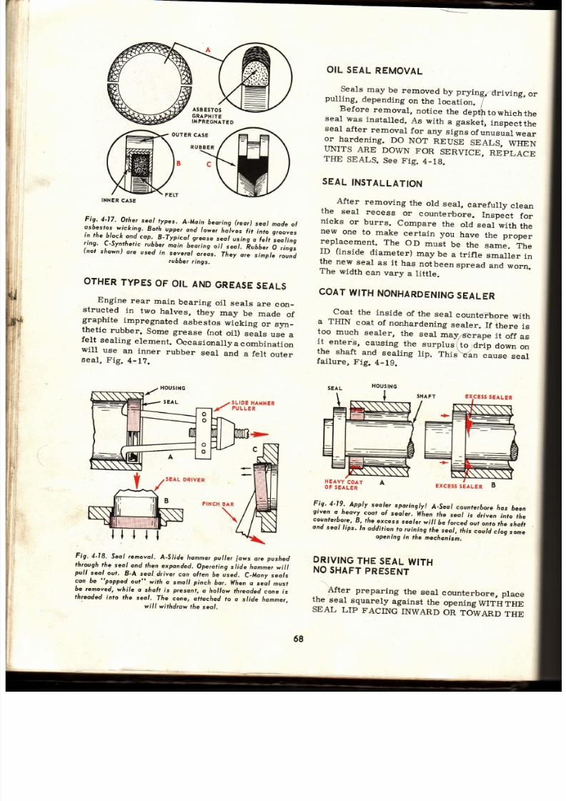
7/26/2019 Auto Service and Repair - Martin W. Stockel
http://slidepdf.com/reader/full/auto-service-and-repair-martin-w-stockel 68/224
INNER
AS E
l:1.
Olr .
Othe¡
seol
t -ypes.
A_Moin
beor ing
reor)
seol
made
l
:-":i:t:;-¡v,i1rn,e.
Both
upper
ond
/o*e,
/ro-l"es
tit-into
s,oo"."
'n
rne
orock
ond
cop.
B-Typicol
greose
seo/
using
o Íer t 'seor ing
r ing.
C-Synthet ic
rubber
noin
bJ.or ing
¡ i lJ.
'É¿¡
er
O
r ings
(not
shown)
o¡e
used
,,
::;;::,,,"^,:1.".
r¡.y'"^-",i^pt.
,ouíd
OTHER
YPES
OF
OIL
AND
GREASE
EALS
Engine
rear
main
bearing
oi l
seals
are
con-
structed
in
two
halves,
they
may
be
rnade
of
graphite
impregnated
asbestos
wicking
or
sJm-
thetic
rubber.
Some
grease (not
oil)
sJals
use
a
felt
seal ing
element.
Occasionally
a combinat ion
will
use
an
inner
rubber
seal
and
a
felt
outer
seal ,
Fig.
4-12.
OIL
SEAL
REMOVAL
Seals
may
be
removed
by prying¡driving,
or
pulling,
depending
on
the
location.
7
Before
removal,
not ice
the
deptfttowhiehthe
seal
was
instal led.
As
with
.
g."t
"\
inspectthe
seal after removal for any signs ofunusual wear
o-r
hardening.
DO
NOT
REUSE
SEALS,
WHEN
IINITS
ARE
DOWN
FOR
SERVICE,
REPIJACE
THE
SEALS.
See
Fig.
4_18.
SEAL
NSTALLATION
..
After
removing
the
old
seal,
careful ly
clean
the
seal
recess
or
counterbore.
Inspect
fo r
nicks
or
burrs.
Compare
the
old
seal
with
th e
new
one
to
make
certain
you
have
the
proper
replacement.
The
OD
must
be
the
same.
The
ID
(inside
diameter)
may
be
a
trifle
smaller
in
the new seal as it has notbeenspread and worn.
The
width
can
vary
a titile.
COAT
WITH
NONHARDENING
EALER
Coat
the
inside
of
the
seal
counte?\ore
with
a THIN
coat
of
nonhardening
sealer.
If
there
is
too
much
sealer,
the
seal
may/dcrape
it
off
as
i l
enlerS,
eausing
the
surplus
(to
arlp
down
on
the
shaft
and
sealing
l ip.
Thiñan
áuse
seal
fai lure,
Fig.
4-19.
SLIDE
HAMMER
PULLER
SEAL
DRIVER
HEAVY
COAT
OF
SEALER
Fig,4-18,
Seo/
rernovo/ .
A-SI ide
hommerpul ler ows
ore
pus/red
through
he
seol
ond then
exponded.
Operot ing
si ide homner
wi l l
pull
seol
out.
B-A
sea
driver
con ohen
6e used.
C-Mony
seols
con
be
"popped
out"
wirh
o smoll
pinch
hor.
Wfien
o seo/
musf
be removed,
while
o
sfioft is
present,
a hollow
th¡eaded
cone
ís
th¡caded
into
fhe
seol.
7[e
cone,
ofioched
to o
s/ide
hommer,
wi l l
wi¡hd¡ow
le
seo/.
Fig.4-19, .
Apply
sealer
spor ingly
A-Seo/
counrer [o¡e
¡os
6een
given
o.heovy
coo
of
seo/er.
lihen
¡he
";l;;-'ei;",
into
the
cou,nterb,ore,
,
fáe
excess
seoler
will
t.
¡or..¿ ""i oito the shol¡cnd seol l ips. ln addi t ion o ruin. ing
áe,
eo/ ,
i i ¡ "
" . "U
clog
some
opening
in
the
mechonism.
DRIVING
HE
SEAL
WITH
NO
SHAFT
PRESENT
..
Afte¡
preparing
the
seal
counterbore,
place
1T.:"1:Ouarely
against
rhe
opening
WTTH
TH E
SEAL
LIP
FACING
INWARD
ON
TOIVEND
THE
HOUSING
>
ExcEss
EALER
B
ó8

7/26/2019 Auto Service and Repair - Martin W. Stockel
http://slidepdf.com/reader/full/auto-service-and-repair-martin-w-stockel 69/224
Gcskets,
Seolants,Seols
AREA
IN
WHICH
THE
FLUID IS BEING
CON-
FIIIED.
If
the lip faces
the other
way
it will
probably
leak,
Fig. 4-20.
Fig.
4-20,
Seol
lip musl foce Íluid
Seol
ín
A
hos 6een ínstolled
,hoctwords.
Lip foces
owoy
lrom
Íluid cousing Íluid
I
to force
seol
Lip
hon
shoh,
cousing
leokoge,
Seol
in I is
correcfly
installed
with
lip
Íocing lluid.
Pressure
ot
2 Ío¡ces
seol ogoinsf shoÍt,
pre-
venting o leok.
USE
SUITABLE
R¡VER
The
driver should be
just
a little
smaller
fabout
.020)
than the seal OD when
the seal
wil l
be
driven
below the surface.
If
the
seal
is to be
driven
flush
(even
with surface),
the
driver
can
be
somewhat wider. In any case, the driver
should
eontact the seal near the outer edge only.
SEVER
STRIKE
THE INNER PORTION OF
A
SEAL. This
might bend the flange inward
and
d stort
the sea ling el.em ent, Fig.
4-21.
If
a seal
driving
setis not available, a section
d
pipe
of the
correct
diameter
canbe used.
Make
Fig.4-21,
Donoged seol..Seol cose 6odly dislorted
6y coreless
iastollation. Punch
struck cose ot
A. AII
drivíng
Íorce
should
be
opplied
ot
B.
This
seol would leok bodly.
sure the
ends are
square. If
a hammer
i7used
to
start the
seal,
followed
up with
a drift,funch.
Be
very
careful to
str ike
at differen\ spots
(near
the
outer edge)
each time. If
the seál be-
gins
to
tip, strike
the
high
side.
REMEMBER:
A
SEAL
IS EASILY
DAMAGED
THROUGII
IM-
PROPER
INSTALLATION
-
BE
CAREFUL:
DRIVE
SEAL
TO
PROPER
EPTH
I f
a locating
shoulder is
used, drive
the seal
snugly
against it.
This
is espeeially
important
if
the
seal inner
edge has
a rubber
sealing
compound
designed
to
flatten
against the
shoulder.
See
B, Fig.
4-16.
When no
shoulder is
used, keep the
seal
square
and stop at the
specifi.ed depth.
If you
dr ive i t in toofar ,youmayruin i t
whi le at tempt-
ing
to
pull
it back.
WHEN EALLIP MUST LIDEOVERSHAFTDURINGNSTALLATION
\
When driving
a seal that must
slip oüer
a
shaft,
use care to see that
the seafñ$lip
is not
nicked
or abraded.
\
If
a
plain
shaft
(no
keyway,
splineb-or holes)
is involved,
check
the
shaft carefull.y for
burrs,
nicks,
etc. If
any
are
found
remove them by
polishing
(shoe
shine motion) with
CROCUS cloth
(a
very
fine
abrasive).
Examine
the
shaft surface
where
the sealing l ips wil l
operate.
It
must be
smooth
at this
point.
If
the
end of the shaft is
chamfered
(beveled),
polish the chamfered area and if the chamfer is
too
steep
(30
aeg.
about maximum)
either
reduce
it
or use a mounting
bullet or thimble. See
Fig.
4-23.
Once
the
shaft is
chamfered and
free
of
scratches,
etc., wipe it
CLEAN and
apply afi lm
of
oil to the full
length.
Place
a small
amóunt of
oil
or soft
grease
on the seal
lip and inner
face.
With the
seal
lip
facing
toward
the
fluid to
be
eonfined
(counterbore
with a thin
coat ofsealer)
carefully slip the sealing
lips
over the
chamfer
onto
the
shaft. Slide the
sealalongthe shaft until
it
engages the
counterbore. Using
a suitable
driver, seat the seal, Fig. 4-22.
MOUNTINGLEEVES
NDBULLETS
When driving
a seal
that must first
slide over
a keyway, drilled hole
or
splines,
start on shaft
with
a
square end, etc., a mounting sleeve or
bullet
should ALWAYS
be used.
This will
pre-
2
t
69
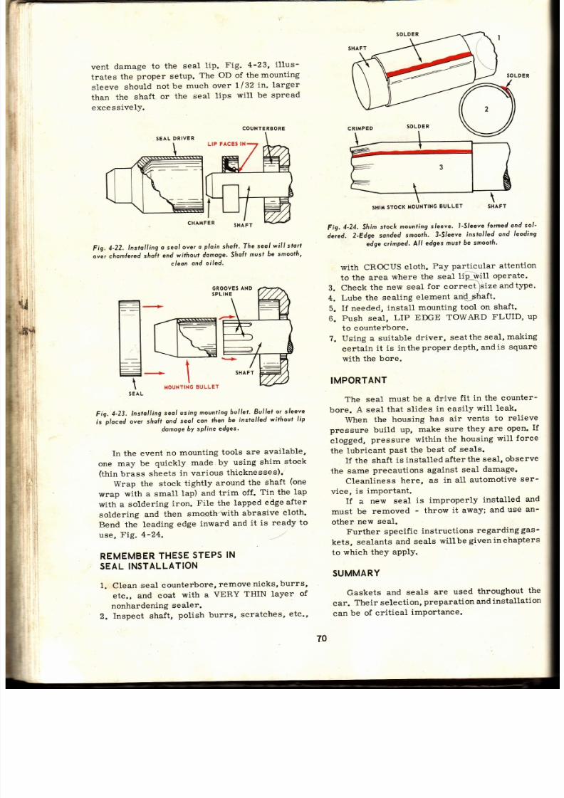
7/26/2019 Auto Service and Repair - Martin W. Stockel
http://slidepdf.com/reader/full/auto-service-and-repair-martin-w-stockel 70/224
vent
damage
to
the
seal
l ip.
Fig.
4-23,
i l lus-
frates
the
proper setup.
The
OD
of
themounting
sleeve
should
not
be
much
over
t lZZ
in. larger
than
the shaft
or
the
seal
lips
will
be spread
excessivelY.
Fig.
4-22.
nstol l ing
o seol
over
o
ploin
shal t '
Ihe
seol
wi l l s lorf
o"ir.ho^ler.d
shoit
end
withoul
damoge.Sfioft
must
6e
smoofh,
cleon
ond oi led'
GROOVES
ND
SPLINE
Fig.
4-23.
lnstol l ing
seo/
using
mounting
.bul let '
Bul l .et
or
sleeve
'is'ploced
or., shoil
ond
seol
con
lhen
6e
insrolled
without
li p
domoge
bY sPline
edges'
In the event
no
mounting
tools
ar:e
available,
one
may
be
quickly
made
by
using
shirn
stock
(thin
brass
sheets
in various
thicknesses); '
Wrap
the stock
tightly
around
the
shaft
(one
wrap
with a
small
lap)
and
trim
off.
Tin the
lap
with
a
soldering
iron.
File the
lapped
edge
after
soldering
and
then
smooth/with
abrasive
cloth.
Bend the
leading
edge
inward
and
it
is ready
to
use,
Fig.
4-24.
,..-'
REMEMBER
HESE
TEPS
N
SEAL NSTALLAT¡ON
1. Clean
seal
counterbo?e,
remove
nicks,burrs,
etc.,
and coat
with
a
VERY
THIN layer
of
nonhardening
sealer.
2.
Inspect
shaft,
polish
burrs,
scratches,
etc',
SHIM
TOCK
OUNTING
ULLET SHAF
Fig.
4-24, Sfi im
stock
movnting
leeve.
l -Slee
e lormed
ond
sol '
deied.
2-Edge
sonded
smootñ.
3-Sleeve
ins¡olled
ond
leoding
edge
crimped.
All
edges
musf
6e smooffi '
with CROCUS cloth. Pay particular attention
to
the area
where
the seal
lfp¡'{X
operate.
3.
Check
the
new
seal
for
correct
)size
andtype'
4.
Lube
the sealing
element
anQ;;Zraft.
5.
If needed,
install
mounting
tool on
shaft.
6.
Push seal,
LIP
EDGE
TOWARD
FLUID,
up
to counterbore.
?.
Using a
suitable
driver,
seattheseal,making
certain
it is
inthe
proper depth,
andis
square
with the
bore.
IMPORTANT
The
seal
must
be a
drive
fit in
the counter-
bore.
A seal
that
slides
in easily
will leak.
When
the
housing
has air
vents
to
relieve
pressure build
up,
make sure
they
are
open.
If
clogged,
pressure
within
the
housing
will
force
the
lubricant
past
the
best
of
seals.
If the
shaft
is installed
after
the
seal,
observe
the same
precautions
against
seal
damage.
Cleanliness
here,
as
in all
automotive
ser-
vice,
is important.
If
a
new
seal
is improperly
installed
and
must
be
removed
-
throw
it
away;
and
use
an-
other
new seal.
Further specif ic
instructions
regarding
gas-
kets, sealants and seals willbe giveninchapters
to
which they
aPPIY.
SUMMARY
Gaskets
and
seals
are
used
throughout
the
car.
Their selection,
preparation
and
installation
can
be of
critical
importance.
F'
COUNTE
BORE
SEAL
DRIVER
LIP
FACES
N
SHIM
STOCK
MOUNTING
ULLET
79

7/26/2019 Auto Service and Repair - Martin W. Stockel
http://slidepdf.com/reader/full/auto-service-and-repair-martin-w-stockel 71/224
Goskets,Seolonts,Seols
Gaskets
provide
leakproof
joints.
They
ar e
:nade
of
paper,
cork, rubber,
asbestos,
steel,
copper,
etc. Different
materials
or
combinations
of
materials
are needed for
specific
applications.
Gaskets
are of single
layer and multiple-
lavs¡
so¡gtruction.
Many
use
steel or copper
uter
layers with
asbestos
center.
The
si.ngle
laver, beaded steel head gasket is popular on
-::gh
compression
engines. Gaskets may
have
=.Cditional
material
around the sealing
edges to
::-crease
unit loading
at these
points.
Gaskets,
once used,
shouldbe di.searded.
Be -
¡are
of kinked
multiple-layer
gaskets.
\tr /here
sealant
use is recommended,
us e
sparingly.
Sealants
of
many
kinds
are available
::
both
hardening
and
nonhardeningtypes.
Select
--::e
proper
type for
the
job
at
hand.
\\¡hen
a
gasket
has failed,
try to determine
xhy,
so
you
can
correct
the
condition.
Oil
seals
are used to
confine
fluids,
prevent
::e
entry of foreign material and often, to
separate
two fluids.
Seals
are
generally
constructed in
three
."rts
-
steel
case, sealing element
and
garter
s:r ing.
Some specialized
seals
use asbestos
;r:cking
or sections
of synthetic
rubber.
Seals
use both
leather
and synthetic
rubber
seal- ing
elements. Many
different
seal l ip de-
s:gns
are
used.
\\hen
install ing
seals, the shaft must
be
s-ooth,
the
counterbore
lightly
coated
withnon-
,Lardening
sealer, and
the seal driven
to the
::oper
depth.
The
seal
l ip should
face
toward
r:e
fluid
to be
confined.
Protect
seal lip
when
:-stall ing
by
chamfering or
using special mount-
::g
tools.
A1ways
use a suítable
driver. Lubricate
:eal
and
shaft
before install ing
the
seal.
Cleanli-
:ess
must
be
observed
at all t imes.
SUGGESTED
CTIVIT¡ES
Determine
how
many
separate
gaskets
ar e
:-rsed
on a V-B
engine.
List
the materials
used
in their
construction.
\Iake
a
gasket
by
placing
the
gasket
material
over
the
part
and tapping_.,a round the
edges
and holes.
Secure a head gasket that has BLOWN (failed).
Examine
it
carefully
and see
if you
can
de -
termine
the
cause.
List
some of the
possible
eauses
of
head
gasket
failure.
\\-ith
a torque wrench,
(following
specifi-
cations),
go
over the fasteners
on an
engine
that
has
been in
service
for
some time. Were
:hey
torqued
to specifications ? If
not,
what
had
happened
during
service.
Whatparteould
the
gaskets
have
playedinthis torque
change?
5.
Check
this
same
car
for
oi l ,
gas
and
water
leaks.
Do
not
overlookthe
transmission,
rear
end
and brake
lines.
Is
the
car
free
of leaks?
If
leaks
are
present,
what
could be
the major
cause
?
6. Inspect some used oil seals that have failed
in
service. What
shape are
they in?
Whathad
happened
to
them? Discount
damage
thatmay
have incurred
during
removal.
50
WHAT'S
LITTLE
LEAK
You might ask why a chapter
is devoted to
such
t'tr i f les"
as
gaskets
and seals.
I t
might
seem that they
are so simple
that a
passing
mention
would be enough.
Surely
they
are not
that important and if
some
part
leaks a trifle,
well
- so
what¡s a l i tt le leakj
The
facts
are that
proper gasket
and seal
selection and
installations
are actually VERY
IMPORTANT. Every
repair
job
is
made
up
of
a series
of steps or
operations
-
some
large
and some
small. All
operations
including the
little thi.ngs
are very
important.
Leaks
are not only messy and ereat{pogr
customer
relations, they
cause
part
failure' 'ahd
expensive comebacks,
plus
real damage to
the
reputation of both
garage
and
mechanic.
In
fact,
even
a
minor leak may cost someoners
l i fe
Letts take
the
case
of mechanic
'lX"
(unfor-
tunately, there are
too many mechanics of this
type). Assigned
to a brake
job,
this
service
technician
had
replaced
the master cylinder and
rear wheel cylinders,
repai.red the
front
cali-
pers,
turned the
rear drums and
frontdiscs,
in -
stalled
new brake shoes and
pads
and replaced
front
wheel seals
and rear axle seals.
Upon
comp.letion,
the
technician bled
and ad-
justed
the brakes, checked
for fluid leaks and,
after road testing, declaredthe
job
complete. The
customer,
a
sales
rep::esentative,
took delivery.
Several
weeks
later, the representative
wa s
r.eturning home.
The
mountain
road
was
dark.
Its
wet surface shimmered
in the
glare
of
the
headlights.
Rounding
a curve,
a rock slide
loomed
out of the night. The representative didnotpanic.
The carrs speed was
not excessive and
thoughit
would be touchy,
there was time
to
stop.
Considering
the slippery
blacktop, the driver
pres
sed
hard on the
brake
pedal,
but not too
hard.
The car
began to
slow,
andthenithappened. The
left rear wheel
grabbed,
Iocked up tight,
lost
traction
and sent
the
carintoaviolentslide.
T
¿
7l
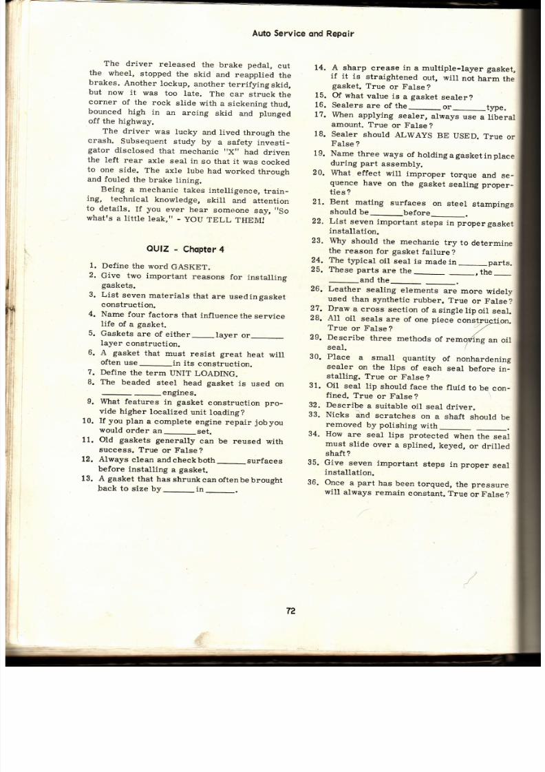
7/26/2019 Auto Service and Repair - Martin W. Stockel
http://slidepdf.com/reader/full/auto-service-and-repair-martin-w-stockel 72/224
Auto Service
qnd
Repqir
The driver
released
the
brake pedal,
cu t
the
wheel,
stopped
the
skid and
reapplied
th e
brakes.
Another
lockup,
another
terrifyi.ng
skid,
but
now
it
was
too
late.
The car
struck
th e
corner
of the
rock
slide
with a
sickening
thud,
bounced
high
in
an
arcing
skid
and
plunged
off the
highway.
The driver was lucky
and
lived
through
the
crash.
Subsequent
study
by
a
safety
invest i-
gator
disclosed
that
mechanic
t 'Xt '
had
driven
the
left
rear
axle
seal in
so that it
was
cocked
to
one
side.
The
axle
lube
had
worked
through
and fouled
the
brake
lining.
Being
a mechanic
takes
intell igence,
train-
itg,
technical
knowledge,
skill
and
attention
to
details.
If
you
ever
hear
someone
sá¡r,
So
whatrs
a
lit t le
1eak,r '
-
] IOU
TELL
THEM:
14. A sharp
crease
in
a multiple-Iayer
gasket,
if
it
is
straightened
out,
will
not
harm
the
gasket.
True
or
False?
15. Of
what
value
is
a
gasket
sealer?
16.
Sealers
are
of the_or_rype.
1?.
When
applying
sealer,
always
use
a liberal
amount. True or False ?
18.
Sealer
should
ALWAYS
BE
USED.
True
or
False
?
19. Name
three
ways
of
hold ingagasket inplace
during part
assembly.
20.
What
effect
wil l
improper
torque
and
se _
quence
have
on
the
gasket
sealing
proper_
t ies
?
21. Bent
mating
surfaces
on
steel
stampings
should
be
before_.
22.
List
seven
important
steps
in proper
gasket
installation.
23.
Why
should
the
mechanic
try
to
determine
the
reason
for gasket
failure
?24. The typical
oil
seal is
madein--parrs.
25. These
parts
are
the_
- ihc
1.
2
3.
4.
OUIZ
-
Chopter
Define
the
word
GASKET.
Give two
important
reasons
for
installing
gaskets.
List
seven
materials
that
are
usedingasket
construction.
Name
four
factors
that
influence
the
service
life
of
a
gasket.
5.
Gaskets
are
of either_layer
or
layer
construction.
6.
A
gasket
that
must
resist great
heat
will
often
use_in
its
constructj.on.
7.
Define
the
term
UNIT
LOADING.
8. The beaded steel head gasket is used on
-engines.
9.
What
features
in
gasket
construction
pro-
vide higher
localized
unit
toading?
10.
If you
plan
a
complete
engine
repair
jobyou
would
order
an_set.
11. Old gaskets
generally
can be
reused
with
success.
True
or False?
Always
clean
and
check both
_surfaces
before
installing
a
gasket.
A gasket
that
has
shrunk
can oftenbe
brought
back
to
size
by_in_.
26.
Leather
sealing
elements
are
more
widely
used
than
synthetic
rubber.
True
or
False?
27. Draw
a
cross
sect ion
of
asingle l ipo i l
seal .
28.
All
oil
seal.s
are
of
one
piece
constr{rgiion.
True
or
False
?
'/ /
29.
Describe
three
methods
ot ,.*o/ng
an
oi l
seal.
30.
Place
a
small
quantity
of
nonhardening
sealer
on
the
tips
of
each
seal
before
in _
stall ing.
True
or
False
?
31. Oil seal l ip should face the fluid to be con_
fined.
True
or
False
?
32.
Describe
a suitable
oil
seal
driver.
33.
Nicks
ánd
scratches
on
a shaft
should
be
and
the
removed
by
polishing
with
How
are
seal
l ips protected
when
the
seal
must
slide
over
a
splined,
keyed,
or dril led
shaft ?
Give
seven
important
steps
in
proper
seal
installation.
Once
a
part
has
been
torqued,
the pressure
wil.1
always
remain
constant.
True
or
False
?
34.
35.
36.
L2.
13.
72

7/26/2019 Auto Service and Repair - Martin W. Stockel
http://slidepdf.com/reader/full/auto-service-and-repair-martin-w-stockel 73/224
{r
Tubing
and hose
are
used
in
many parts
of
the
car. Brake
systems,
fuel
delivery,
vacuum
applic
ati on
s, air
c onditioning,
trans
mi
s si on fluid
cooling,
engine
cooling,
heating, power
steering,
lubrication,
instrumentation,
etc.,
all
uti l ize
either
tubing
or
hose,
and in
some
instances,
both.
Selecting,
using
and working
with
tubing
is
a
part
of
most
repair
jobs.
It
is
imperative
that the mechanic be thoroughly familiar with
the
different
types,
their
application
and
proper
installation.
TUBING
MATERIAL
Annealed
(soft)
copper,
half-hard
copper,
stee1,
aluminum,
plastic
and
stainless
steel
ar e
some
of the
materials
used inthe
manufacturing
of
tubing.
Although
alt
of these
are found
in
the
automotive
field,
the
most
commonly
usedt¡pes
are
steel
and
copper.
Copper
is
more
easily
bent
than
steel
but
is
not
as strong. Fig. b-1, shows the amount of
pressure
various
kinds
of 3/16
in. OD
(outside
diameter)
tubing
with
a
wall
thickness
of
arouñd
.020 in.
wil l
withstand.
These
are
considered
safe
working
pressures
when
a safety
factor
of
five
to
one
(material
five
times
stronger
than
anticipated
working
pressure)
is
desired.
After
studying
Fig.
b-1,
i t
becomes
obvious
that
the
mechanic
must
KNOW
what
material
is
used
in
the
tubing
he
is working
with.
He
must
also
have
a fairly
accurate
knowledge
of
the
pressures
and
temperature
produced
in the
system
on which
the
tubing
will
be
used.
Keep
in
mind
that
both
the
power
steeringandbraking
systems
can
develop pressure
in
excess
of
1000
pounds.
COPPER
UBING
Copper
tubing
i.s
rustproof,
easy to
bend
an d
forms
good
joints.
It
can be
used
for gas
lines,
vacuum
lines,
lubrícation
lines
and
for
other
low pressure
applications.
Copper
is
subject
to
work
hardening
(the
material
becoming
hard
and brittle
from
bending)
and
should
therefore
be
protected
from
excessive
vibration.
NEVER
USE
COPPER
TUBING
FOR
BRAKEORPOWER
STEERING
WORKJ
STEELTUBING
When
properly
coated
to prevent
rust,
steel
tubing
is
suitable
for
almost
all
automotive
applications.
When
used
for
high pressure
sys_
tems
such
as
brakes,
the
steel
tubing
should
be
of
the
double
wrapped,
brazed
and
tin_plated
l , /4
tN .
3/ló
tN.
.062
200
.023
300
.0t8
50 0
.0¡
8
|
,000
.020 t.000
.020
2,000
.020
2,000
.020
2,000
.020
3.000
.01
5,000
Fig.
5-1. Pressure
áorf.
Note
he
vo¡iotion
n
sofe
wor/<ingres_
sure o¡
the
vo¡ious
moterials.
type. The
double
wall
construction
gives
good
strength
and
makes
the
tubing
easy
to bend.
The
tinplating
protects
it from
corrosion.
PLASTIC UBING
Polyethylene
and
nylon
are
two
of
the
ma-
terials
used
in the
construction
ofplastic
tubing.
Soft
plastic
tubing
has
the
advantage
of flexi-
bil i ty,
resistance
to
corrosion
andworkharden-
ing.
I t
wil l
not,
however,
stand
high
pressures\
and
excess
heat.
It
can
be
used for
fuel,
vaeuum
I
Chapfer
5
TUBING
NDHOSE
MATER
AL
Polyethylene
*
Ny on
35 A
luminum
5250
A
uminum
Anneoled Copper
Holf-hord
Copper
Double
Wrop,
Brozed
Steel
l
0l 0 Sree
Anneo
ed Stoinless
Steel
4130
Sreel
=
AT
70
DEG.
F.
WALL
PRESSURE
O.D
THICKNESS
LBS.
73

7/26/2019 Auto Service and Repair - Martin W. Stockel
http://slidepdf.com/reader/full/auto-service-and-repair-martin-w-stockel 74/224
Auto
Service
ond
Repoir
and
some
lubrícation
lines.
Special
inserrs
ar e
needed
to
attach
the
soft
plastic
to
conventional
tube
fit t ings.
HANDLING
TUBING
When emoving tubing from a roll, place the
ro l l
on
a clean
bench
inanuprightposit ion.
Hold
the
free
end
of the
tube
with
one
hand
while
ro _
tating
the
rol l
over
the
bench
with
the
other.
Never
lay
the
roll
f iat
and
pull
the
tubing
upward
as i t
wi l l
be
twisted,
Fig.
5-1A.
CITAMFER
\ .cur
or¡
SQUARELY
Fig,
5-IA.
Proper
ethod
l removing
ubíng
rom
oll .
Avoid
working
(bending)
the
tubingmorethan
necessary.
Store
tubing
where
no
heavy
tools
or
parts
are
liable
to
cause
dents.
Keep
the
open
end
taped
to prevent
the
entry
of foreign
material.
CUTTlNG UBING
Tubing,
especially
when
the
ends
are
to
be
flared,
must
be
cut
off
SQUA3,ELY.
Any
burrs,
either
on the
outside
or
inside,
mustbe
L-olrea,
ig.
5-2.
Fig.
5-3,
Tube
cutter.
Note
reomer
blode
n
t/re
closedposirion.
(lnperiol
MÍg,
Co,)
Although
a f ine-tooth
hacksaw
can
be
usedto
cut
tubing,
a faster
and
better
method
is
to
us e
a tube
cut ter,
Fig.
5-3.
The
cutter
is placed
around
the
tube,
th e
cutter
wheel
is
brought
into
f irm
contactandthe
cutter is revolved around the tubing. After each
complete
revolution,
the
cutter
wheel
is
t ight_
ened.
DO
NOT
OVERTIGHTEN,I
Repeat
this
process
until
the
tubing
is
cut
off, Fig.
b_4.
, /<\
Fis.
-4.
,,n^r.: :,
wheét
by
turnins
handte
.
REMOVE
URRS
After
cutting,
you
will
probably
notice
a
burred
edge,
especially
on
the
inside.
Remove
the
burr
by
using
the
reamer
blade
onthe
cutter
tool.
Ream
only
long
enough
to
removetheburr.
Excessive
reaming
will
ruin
the
end
forflaring,
B,
Fig.
5-2. When reaming HOLD THE END OF
THE
TUBING
DOWNWARD
SO THAT
THE
CHIPS
WILL
FALL
FREE.
See
Fig.
b-b.
TUBING
ONNECTIONS
There
are
three
'basic
types
of
tube
con_
nections
-
the
FLARE,
the
COMPRESSION,
an d
the PIPE.
All
have
variations
in
design
and
are
commonly
use.d.
Fig.5-2.
A-Tubing
cut
ot
on
ongle
and heovi ly
burred.
B_Cír
squorely
but ¡eomed
excessively.
C-Cut
squárely
ond
¡eomed
proper ly.
REAMER
LADE
ROLLERS
CUTT|NG
tVHEEL
74

7/26/2019 Auto Service and Repair - Martin W. Stockel
http://slidepdf.com/reader/full/auto-service-and-repair-martin-w-stockel 75/224
Tubing
qnd
Hose
F LARE
YPE
CONNECTION
In
the
flare
connection,
the
end
of
the tubi.ng
:s
spread
(flared)
outward
at an
ang1e.
The
tube
: : t t ing
securely
grasps
both
sides
of the
f lare
:bus
producing
a leakproof
joint.
Fig.
b-bA,
:l-lustrates
one
type
of flare
connection.
Fis.5-6,
Two
(lore
onsles.
A-J. l .C.
37 deg.
B-SAE
45
deg.
Fig.
5-7.
A-Sing/e-/op.
B-Doob.le-lap
lore.
Fig.
5-5,
Removing
bu¡¡s
with
c, reomer,
FITTING
OD Y
F
LARE
Fig.5-54.
SAE 45
deg,
l lore
connecfion.
Norice f iow
Ílore
is
pinched 6etween
(itting
body ond nut.
FI.ARE
ANGLES
There
are
two
flare
angles
-
B?
and 4b
Cegrees.
Be
certain
you
determine
the
on e
:eeded,
Fig.
5-6.
FLARE
TYPE
The
flare
may
be
SINGLE
or DOUBLE-LAP
:ype.
WHEN
FLARING
DOUBLE-WRAPPED,
BR..{ZED
STEEL
TUBING,
ALWAYS
USE
A
DOUBLE-LAP FLARE. This type of tubing, if
a
single-lap
is
used,
will
SpLITI
See Fig.
b_?.
FLARE
MUST
BE
ACCURATELY
ORMED
The
flare
must
be
smooth
and
square
with
:he
centerline
of the
tubing.
Careless
cutting
or
:rrproper
use
of the
flaring
tool
wil l produce
CONTACT
|,m
UNEVEN
\
r------1\
Li-l\
FLARE
\
SHOULDE
COCKED
d
SPLIT
O.K.
--..-¿
-f,1
.--}.J
jlJ
FU
LL
CONTACT
Fig.5-8.
Flore must
6e
sguore
wi¡h
the
tu6e
cenfer
l ine,
ond
ol
lhe
correcl
s ize.
weak
and
uneven
flares.
These
wi l l
a lways
LEAKI
When
a
flare
is
made
incorrecily,
cut
it
off
and
form
a new
one, Fig.
5-g.
FORMING DOUBLE-LAP LARE
After
cutting,
reaming,
and
determining
the
proper
flare
angle,
insert
the
tubing
in
a flaring
tool.
The
tool
shown
in Fig.
5-g,
wiII
produce
either
a
single
or double-lap
flare.
Although
you
should
always
follow
instruc-
tions
provided
by
the
manufacturer
of the
tool
FLAT
REAMER
\
ar r , wrLL
FALL
FREE
FLARE
TOO
LARGE
75

7/26/2019 Auto Service and Repair - Martin W. Stockel
http://slidepdf.com/reader/full/auto-service-and-repair-martin-w-stockel 76/224
PTERS
-/'
Fig. 5-9.
One
type ol l lor ing
¡ool .
This
¡ool
wi l l
produce
both
single
ond double- lop
lores.
you
are using,
you will f ind that
in
general, the
actual
forming
process
is similar
for all t1pes.
To
use the
tool i l lustratedin
Fig.
5-9, arrange
the
gripping
blocks sothatthe correct
size
tubing
hole is directly beneath the flaring cone. Rotate
the
adapter
plate
until
the correct
size
adapter
is beneath the cone. Shove
the
tubingthroughthe
gripper
blocks until
it strikes
the adapter.
Tight-
en
the block securely
so
the tubing
cannot
be
forced
downward under
f lar ing
pressure,
Fig.5-10.
CONE FEED SCREW
GRI
PPER
BLOCK
SERRATIONS
Fig.
5-10.
lnserting
tubing. Push
rubing (l
)
in until odopter strikes
odopter
plote
(2).
T¡ghten
gripper blocks
(3).
Run the f laring cone
down
until
it forces
th e
adapter
against
the
gripping
blcick.
This
causes
the adapter
to
BELL
the end
of
the tubing.
This
is the
first step
in doing a
double-lap
flare,
Fig.5-11.
FEED SCREW IGHTENEO
fS i l t t *
F0RcED.
.{-3
5- l l .
Bel l ing
tube end.
Tighten
cone
feed screw
( l)
un¡ í l
odoptersfr ikes
gr ipper
block
(2) .
FINISHED
LARE
3->-
Fig. 5-12. Finished
lore.
Adapter
wungoside
(2)
ond cone
o¡ced
(I)
in¡o bel led end.
Turn the f laring cone back, swingthe adapter
out
of the
way,
and run
the
cone
tightly
down
into the bel led tubins.
This willformthe
finished
f lare,
Fig.5-12.
REMEMBER
-
ALWAYS SLIDE
THE FIT-
TING
NUT ONTHE TUBINGBEFORE
FLARING,
Fig.5-13.
CLEANTUBING
Wtren all
cutting,
reaming and
flaring have
been accomplished,
use compressed
air and
NU T
Fig. 5-13. Sl ide
nuf on tuhe be(ore
Ílor ing.
Fig.
I
76

7/26/2019 Auto Service and Repair - Martin W. Stockel
http://slidepdf.com/reader/full/auto-service-and-repair-martin-w-stockel 77/224
Tubing
ond
Hose
blow out
the line
to remove
any chips
or
other
foreign material.
Place
the tubing
in
a clean
spot
unti l
ready to
install.
I f ,
duringinstallation,
there
is any chance
of
dirt or
grease being
jammed
into the ends, cover
the ends
with
masking
tape.
REMEMBER
-
THE
SLIGHTEST
AMOUNT
OF FOREIGN
MATERIAL
MAY
RUIN
THE
JOB
-
KEEP
THE TUBING SPOTLESS:
BENDING
UBING
Soft
copper and
thin-wall
steel
tubing
in the
more commonly
used sizes
can
be bent
by
slipping
a
bending spring
over
the tubing
then
forming the
bend
with the
hands.
When using
a
bending spring,
make sure
it is the
correct
size.
Bend the tubing a
tr if le more than
needed.
When it
is bent
back to
the exact
shape,
the
spr ing
can
then
be readi ly
removed,
Fig. 5-15.
Fig.
5-15.
Using
spring
ube
bender.
Stiffer
tubing
may
be
handled
with a
lever-
type bender.
This
tool
wil l make
uniformbends.
When appearance
is important,
it
is
often
used
on softer
tubing
also.
Fig.
5-16,
shows
tubing
inserted
in the
tool.
Note that
thetoolis
marked
in degrees
to assist
in controll ing
the amount
of
bend,
Fig.
5-16.
In
Fig.
5-1?,
the
handles
have been
closed
and
the tubing
bent.
The mechanic
has opened
the handles,
loosened
the
holding
foot, and
is
removing
the
tubing.
It is often advisable
to bend
tubing
prior
to
flaring.
However,
if the
bend
must
be
close to
the
flare, make
the
flare
first
so
the
bend
will
not
interfere
with the
flaring
tool.
To facil i tate
assembly,
never start
the
bend
too close
to
the
flare. Allow
about
twice
the
length of the nut,
Fig.5-18.
REMEMBER
-
WHEN
BENDING
TUBING,
BE VERY
CAREFUL
TO AVOID
KINKS
AN D
FLAT
SPOTS:
Once kinked
or
flattened,
the
tubing
wil l
restr ict
flow
and lead
to trouble.
ALWAYS
USE
A SUITABLE
BENDING
DEVICEJ
Fig. 5-
1BA.
Fig.
5-16. Tubing
inserted
n mechonical
bender.
Fig.5-17.
Bend completed,
hondles
open, lubing
beíng
removed.
( lnperiol
Bross
Mfg.
Co., )
FITTIN
G
CONN
CTEO
NUT
FULLY
RELEASED
\
START
BEND
HERE
Fig.
5-18. AIlow
enoughspoce
befween
fi t t ing ond
6end so
thof
the nut
wi l l
s/ ide
6oc/< s sl lown.
ññ
FLATTENED
o K
bending,
ovoid
kinking
or l lol tening
lubing.
l * rwo
NUr -excrxs
+l
B EN DING
SPRING
77
Fis. 5-18A.
When

7/26/2019 Auto Service and Repair - Martin W. Stockel
http://slidepdf.com/reader/full/auto-service-and-repair-martin-w-stockel 78/224
Auto
Service
qnd
RePqir
INSTALLING
TUBlNG
Tubing
must- usually be bent
directions
to
provide
a
proper
ln
one
or more
flt .
In
order
to
AVOID
TRAIGHT
UNS
Straight
runs, especially
if
short,
wiII
not
work
well as the slightest shift ing
between the
two units
will impose a strain on
he
connect ions.
They
are also
diff icult to
install
or
remove,
Fig.
5-19.
SUPPORT LONG
RUNS
Tubing
can
fai l
if subjected
to excessive
vibration. Secure
long runs
with
clips or
hold-
downs.
Junction
or
distribution blocks and other
heavy units
must be supported,
Fig.
5-20.
TUBING
NDS HOULD
ALIGN
WITH
FITTINGS
To
prevent
cross-threading
(threads
st a
and turned in a
cocked
posit ion
thus
ruining
threads) and leaks, as well as to facil itate in-
stallation,
make
sure
tubi.ng ends are
Ín
with the fitting.
The
tubing should
NOT have
be
sprung
into
alignment.
Fitt ings should sta
and run up several
turns
with f inger
pressu
only.
If they start
hard,
check
for
dam
threads, alignment
and size.
DO NOT CROSS-
THREAD THE
FITTING.
See
Fig.
5-21.
DETOUR
ROUND OT
SPOTS
Never run tubing
too
close
system.
Keep it as
far
away as
necessary, instl[ a heat baffle
tubing,
Fíg.
5 22.
to the exhau
possible
an d
or insulate
Fig.5-19.
Avoidstroight
uns
A,
B,
C,
by instoll ingubing
s
shown
n A-l
B-l
ond
C-l
insure satisfactory service, a-
few important
rules should
be
kept in mind
prior
to actual
bending.
ASSEMBLE
OTH
ENDS EFORE
FINAL
T¡GHTENING
Connect the tubing
long leg end
first.
Le a
the
fit t ing
loose so
that the other
end can'
moved enough
to make
the
connection.
BOTH
connect ions
are
made, t ighten.
Use dis-
MOUNTING
OL T
SHUT
OFF
COCK
-
-
l , touHrtxc
lt e
Y DISTRIEUTION
BLOCK
Fig. 5-20.
Long tubing ¡uns
ond reloted units
musf
6e supporfed with mounting
clips
ond
6olrs.
78

7/26/2019 Auto Service and Repair - Martin W. Stockel
http://slidepdf.com/reader/full/auto-service-and-repair-martin-w-stockel 79/224
Tubing
qnd
Hose
: :et ion when
tightening.
If
torque values are
"".-ailable,
use them.
This
chapter
wil l
give
yo u
i:neral
instruet ions
on
the
amount of
t ightening
-¡eda¡ l
REMEMBER:
MANY FITTINGS
ARE
EASY
TO
TWIST
OFF
-
BE
CAREFUL.SeeFie.S-23.
F¡TTINGS
Proper
select ion
of
f it t ings is important.
The
:orrect
choice
will
speed up the
job
and
insure
:roper
operat ion.
Fit t ings
are
designed tomake
::ther
a
f lared,
compression,
or
pipe
connection.
The f lare
f it t ing
just
discussed
can
be of
th e
Sin
type,
Fig.
5-25, or the
INVERTED type,
- ' -9.
5-26.
WHEN
O USE
FLAREFITTINGS
Flared f it t ings
CAN be used on any
type of
: : 'r ing (copper,
aluminum,
steeI, etc.)
that wil l
TUBING
€
NU T
--CONNECTOR
Fig.
5-21,
Properol ignmen s impor-
tont,
The
nut in
A
wouldc¡oss-th¡eod.
:00
cLosE
:UBING
SHOT
Fig. 5-23.
Assemble
ubing ong eg end
irst
os in
A.
l( sho¡t
nd
is ossemó/ed
irst,
otherendwi l l
be
diÍ l icul¡ o
connec|, .
lend
itself to f laring.
Flared f it t ings MUST
be
used on
high
pressure
automotíve applicat ions
such as the
brakes and
power
steering.
ASSEMBLING LARED FITTINGS
Slide
the nut,
long or short
dependingonuse,
on
the tubing.
Flare
the
tubing
making
certain
ffire@
Fig.
5-25.
SAE
45 deg.
( lare
l i t t ing. The nut th¡eads over
the l i ¡ -
ting body.
(lleotherheod
Co.)
EXHAUSTPIPE
Fig.
5-22.
Protect tubing lrom heoting
A
by either instolling o
heot
bo#le
B
or
rerouting
C.
NUT
(SHORT
*'mrd---r| ñJm[r,L
llutttt{.,,1E¡¡¡tl{q:
Fig.
5-26.
Inverled 45 deg.
f[are
(it t ing.
The
nut lhreods
nto fhe
Íitting body.
k)
ry
"
aottat\
@
il4
F xur
trrLL
LINEuP
WRONG
79

7/26/2019 Auto Service and Repair - Martin W. Stockel
http://slidepdf.com/reader/full/auto-service-and-repair-martin-w-stockel 80/224
SLEEVE
PINCHÉS
UBING
Auto Service
ond
Repoir
-A
ffiAIil
ffii{iil
\-J
ilm||tt
ffirrl'r si
Fig.5-27.
Seporoteleeve
compression
it t ing.
NoficeÁow
upon
tightening,
fie
sleeve
pincfies
he ubing.
the
flare is
of the
correct angle and
width.
Double-f lare
aI1 brazed steel tubing,
thin-wall
tubing
and all high-pressure
applicat ions.
Align
the tubing with the fitting.
Shove
the
flare
against the
fitting
seat
and run the nut up
f inger
t ight. Using
a f lare nut wrench, bring the
nut up
solidly at
which point you
will feel
a
firm
metal-to-metal contact
(f lare
securely pinched
between
nut and
fitting
body).
At this
point, give
the nut
an addit ional 1
6
turn.
FLARELESS
COMPRESSION
YPE FITTINGS
A
sleeve,
either a separate unit or designed
as
part
ofthe
nut, is
used
in
compression
fittings.
When
the fitting
and nut are drawn together, the
sleeve
is
compressed against
the
tubing,
f i t t ing
and nut.
The
separate sleeve-type
compression
fitting is
pictured
in Fig.
5-27.
The
DOUBLE
COMPRESSION type,
usingthe
nose
of
the
nut
as
the
sleeve,
is
shown
in
Fig.5-28.
WHENTO USE
COMPRESSION
ITTINGS
Compression fittings may
be used on low-
pressure
applications sueh as vacuum, fuel
an d
lubrication
lines. Since no
flaring
is
required,
connections
are
quick
and
easy
to make. DO
NOT
USE
ON
BRAKE
AND
POWER
STEERING
SYSTEMS.
ASSE
MBL
ING
COMPRESSION FITT¡NGS
Slide the nut, followed by the sleeve, on the
tubing. When
the tubing is
aligned with the fitting,
insert
the
tubing
as
far
asitwil lgo.
While
hold-
ing
the
tubing in,
run up the nut finger tight.
Using
a
flare
nut
wrench,
bring
the
nut
up until
the sleeve
just
grasps
the tubing.
For
tubing
size 1/8, 3/16
and tl4-ín.,
give
the
nutan
addi-
tional one and
one-quarter
turn.
For
5/16-in.
Fig.5-28. Double compression
fitting.
Vlhen tightened, tfie
nose
ol the
nut is fo¡ced
ogoinst
ihe tubing.
tubing
-
one and three-quarter
turn and for
al l
s izes
3/8
to f - in . , two
and one-quarter turns.
WHILE
TIGHTENING,
HOLD
THE TUBING
IN
THE
FITTING:
The
foregoing
tightening procedure
applies
only to new
compression
fittings.
When
assem-
bling USED fittings, bring
the nut
up
firmlywith
no additional
,turns.
PLAST¡C
TUBING
COMPRESSION
FITTINGS
When RIGID plastic
tubing
is
used, a regular
separate sleeve
compression fittingwill
suffice.
However,
if
the tubing is
SOFT,
a specialinsert
is
placed
in
the
end so the
sleeve will not
crush
the tube, F ig.
5-29.
Fig.5-29. Fitting
br soft
plostic
tubing.
The
inse¡f
is needed
to
prevent
sleeve from
crushing
tubing,
Fig. 5-30.
Flexible compression fiffing.
ollows heovy vibration
without imposing
tubing.
fñe composífion
sleeve
on
undue sfroin on lñe
80

7/26/2019 Auto Service and Repair - Martin W. Stockel
http://slidepdf.com/reader/full/auto-service-and-repair-martin-w-stockel 81/224
Tubing
ond Hose
OTHER
PECIALIZED
OMPREsSION
YPES
One
type
of
compression
f it t ing,
designed
for
resistance
to
extreme
vibrat ion,
is
shown
in
Fig.
5-30.
Instead
of the
convent ional
metal
s leeve,
a
composit ion
sleeve
mater ia l
is
used.
Note
how
the
tube
can
flex
without
bending.
This
f i t t ing is for low-pressure use.
The
Ermeto
is
a
compression
type
f i t t ing
designed
to
withstand
high pressure.
Heavy,
dif f icult
to f lare
tubing
may
be
handled
withthis
design,
Fig.5-31.
Fig. 5-31.
Ermeto
high-pressure
omp¡ess
on Í i t t ing.
( lnperio l
Bross Mlg.
Co.)
Another
compression
type f it t ing
that
wiiL
handle
high pressure
is
shown
in
Fig.
5-32.
NUTLENGTH
Nuts
for
both
f lare
and
compression
f it t ings
are
avai lable
in
both
standardandlongvers ions.
Where
the
installat ion
is
subjected
to heavy
Fig.
5-32,
his compression
it t ing
s designedor high ressure.
vibrat ion,
use
the
long
nut. This
wil l
tend
to
support
the
tubing
a
greater
distance
from
th e
actual
conneet ion.
Fig.
b-33,
i l lust rates
a
com-
pression-type
UNION
using
the
standard
nut.
The
long
nut,
on
a
similar
union
is
used
in
Fig.5-34.
PIPE
FITTINGS
The
pipe
fit t ing
uses
a
tapered
thread
that
when
fully
t ightened
will produce
leakproof
jo ints.
A
development
in pipe
threads,
cal led
Fig,
5-33,
Compression
ype
uníon
using
stondord
ength nut
Fig.
5-34.
Compression
ype
union
using
the
long
length
nut.
the DRYSEAL
PIPE
THREAD,
produces
leak_
proof joints
without
undue
turning
force.
Thisis
accomplished
by
a dif ference
in
the
truncation
(cutoff point) of the thread root and crest. As
the
fit t ing
is
drawn
together,
the
root
(bottom)
and
crest
(top)
of
the
threads
come
in
contact
before
the
f lanks
(s ides).
Final t ighteningcauses
metal- to-metal
contact
between
root ,
crest
an d
flank.
Fig.
5-36,
shows
a
secti.on
of
steel
pipe
joined
to
a hex
NIPPLE
by
using
a COUpLING.
Note
the
tapered
threads.
fI Il t#l
' 't 't=
lililllullilil
+g=
ilillltl=
Fig. 5-36. Pipe
Í i t t ing .
Nofe ropered
h¡eods.
(Weoráerheod
o. )
81
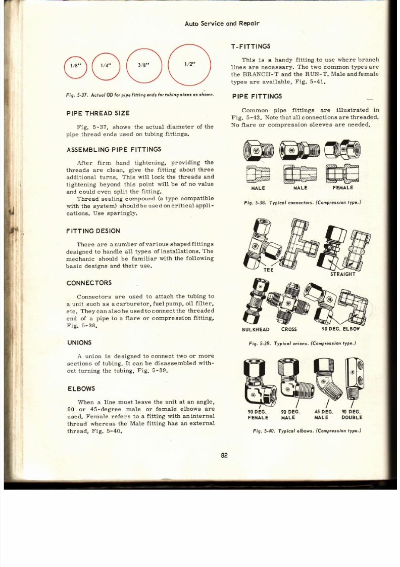
7/26/2019 Auto Service and Repair - Martin W. Stockel
http://slidepdf.com/reader/full/auto-service-and-repair-martin-w-stockel 82/224
Auto
Service
qnd
Repqir
rerñr¡r¡
_/vv\_/
Fig. 5-37. Acluol OD lor pipe Íitting ends or tuhing sizesot sÁ-own
T-FITTINGS
This is
a
handy
fitting
to
use
where
branch
lines are necessary.
The
two common
t¡pesare
the
BRANCH-T and
the
RUN-T.
MaIe
andfemale
types are available,
Fig.
5-41.
PIPE FITTINGS
Common
pipe
fittings are
il lustrated
in
Fig.
5-42.
Note
that all connections
are
threaded.
No flare or compression
sleeves are
needed.
PIPE
THREAD
IZE
Fig.
5-3?,
shows
the actual
diameter of
th e
pipe
thread ends
used on tubing
f it t ings.
ASSEMBLING
IPE FITTINGS
After
firm hand tightening,
providing the
threads are clean,
give
the
fitting
about
three
addit ional turns.
This wilL
lock
the threads
and
tightening beyond
this
point
wil l be of
no value
and could even split the f it t ing.
Thread
sealing compound
(a
type compatible
with the system) shouldbe
used on crit ical
appli-
cat ions.
Use
sparingly.
FITTING
DESIGN
There
are
a number
of
various
shaped
fittings
designed
to
handle all
types of installat ions.
The
mechanie
should
be
familiar
with
the
foll.owing
basic
desígns and
their use.
CONNECTORS
Connectors
are
used
to attach
the
tubing to
a unit such
as acarburetor,
fuelPumP,
oil
f i l ter,
etc.
Theycan
alsobe
usedtoconnectthe
threaded
end of
a
pipe
to a
flare or compression
fitting,
F ig.5-38.
UNIONS
A
union
is designed to connect
two or
more
sections of
tubing.
It
can
be disassembled
with-
out
turning the tubing,
Fig. 5-39.
ELBOWS
When
a
line must leave
the
unit at an
angle,
90 or
4S-degree
male
or
female elbows
ar e
used.
Female refers
to a
f it t ing with aninternal
thread
whereas the
Male fitting
has an external
thread,
Fig.
5-40.
;
. i
ii
,ii
ii
i l ,
Ww
5
DEG.
90
DEG.
MALE
DOUBLE
90 DEG.
90
DEG.
FEMALE
MALE
MWff i
i----+-l--J lllHF--l+--'-t lilHHhtf--i
w
W¿a We
MALE
MALE
FEMALE
Fig.
5-38. Typical
connecfors.
Compression
ype.)
BULKHEAD
90 DEG.
ELBOW
Fig, 5-39.
Typicol unions.
(Compression
ype., l
STRAIGHT
cRoss
82
Fig.
5-40. Typical
elAows.
(Compression
ype.)
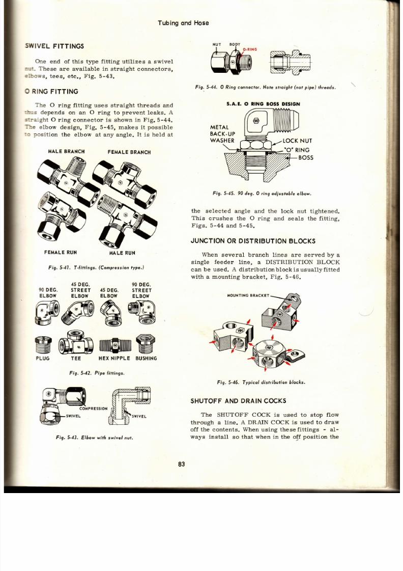
7/26/2019 Auto Service and Repair - Martin W. Stockel
http://slidepdf.com/reader/full/auto-service-and-repair-martin-w-stockel 83/224
Tubing
qnd
Hose
sIryIVEL
ITTINGS
One
end of this type
fitting
utilizes
a
swivel
:r¡ 1. These
are
available
in
straight connectors,
€lbows,
tees, etc .,
Fig.
5-43.
O RING
FITTING
The
O
ring fitting uses
straight
threads
and
rh::s
depends
on an
O
ring to
prevent
leaks.
A
s:raight O
ring
connector
is
shown
in
Fig.5-44.
Ite
elbow
design,
Fig.
5-45,
makes
it
possible
lto
position
the
elbow at any angle.
It
is
held
at
MALEBRANCH
FEMALE
BRANCH
FEMALE
RUN
MALERU N
Fig. 5-41. T-l i t t ings.
(Compression
ype.)
Fig. 5-44. O
Ring
connecto¡.
Nofe straight
not
pipe)
/rreods.
METAL
BACK.UP
WASHER
IOCK NUT
.O RING
BOSS
Fig.5-45. 90deg.O ring odiustoble lbow.
the
selected angle
and the lock nut tightened.
This
crushes the O
ring and
seals
the fitt ing,
Figs. 5-44
and
5-45.
JUNCTION
R
DISTRIBUTION
LOCKS
When
several branch l ines are
served
by
a
single
feeder
line,
a
DISTRIBUTION BLOCK
can
be used. A dis tr ibut ionblock is
usual lv f i t ted
with a mounting bracket, Fig.
5-46.
MOUNTING RACKET
Fig. 5-46. Typicol
distr ibution blocks.
SHUTOFF ND
DRAIN
OCKS
The
SHUTOFF COCK
is
used
to
stop
flow
through a l ine.
A DRAIN COCK
is
used
to draw
off
the contents. When
using thesefitt ings
-
al -
ways install
so that
when
in the off
position
the
,i l
,l l
trl
i{
I
,ri
;, í
í
E
i¡
gffiulwiltrrx
LUG
45
DEG.
90 DEG. STREET
ELBOW
ELBOW
90 DEG.
45 DEG. STREET
ELBOW
ELBOW
TEE HEX
NIPPLE
BUSHING
Fig, 5-42.
Pipe
ittinss,
S.A.E.
O
RING
BOSS
DESIGN
Fig.
5-43.
Elbow
wirh
swivel nut.
83
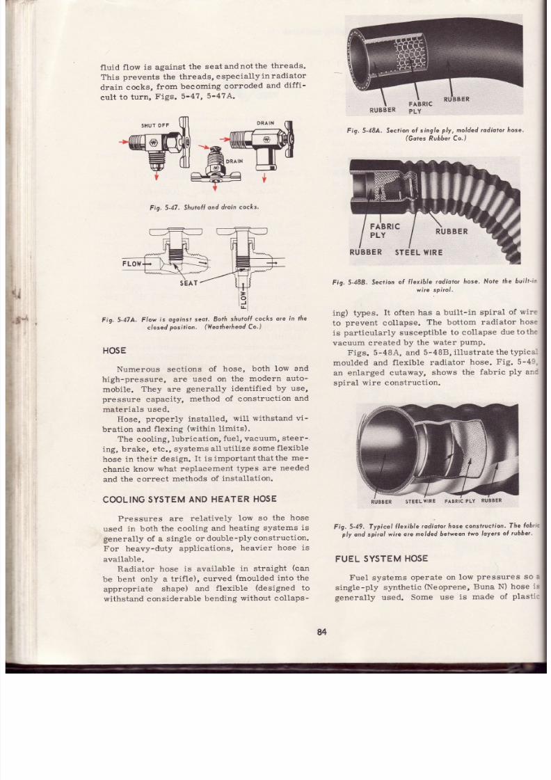
7/26/2019 Auto Service and Repair - Martin W. Stockel
http://slidepdf.com/reader/full/auto-service-and-repair-martin-w-stockel 84/224
f luid
f low
is against
the seatandnotthe
threads-
This
prevents the
threads,
espeeially
in radiator
drain
cocks,
from
becoming
corroded
and
diff i-
cult
to turn,
Figs.
5-47,
5-47
A.
Fig.5-47.
Shu¡ol l
ond d¡oin
cocks.
Fig.
5-47A.
Flow
is ogoinst
seot ' Both
shutol Í cocks
o¡e ín the
closed
posí t ion.
(Vleothe¡heod
o, )
HOSE
Numerous
sections
of
hose,
both low
an d
high-pressure,
are
used on
the
modern auto-
mobile. They are generally identif ied by use,
pressure
capacity,
method of construction
an d
materials
used.
Hose,
properly installed,
will withstand
vi-
bration and
flexing
(within
limits).
.
The
cooling,
lubrication,
fuel,
vacuum,
steer-.
ing,
brake, etc.,
systems
a1l
util ize some
flexible
hose in their
design.
I t is important that the
me -
chanic
know
what
replacement
types
are
needed
and the correct
methods
of
installat ion.
COOLING
YSTEM
NDHEATER
OSE
Pressures are relatively low so the hose
used
in both
the cooling
and
heatlng
systems
is
generally
of
a single
or doubLe-plyconstruction.
For heavy-duty
applieations,
heavier
hose is
available.
Radiator hose
is available
in straight
(can
be
bent only
a trif le),
curved
(moulded
into the
appropriate
shape)
and
flexible
(designed
to
withstand considerable
bending
without collaps-
Fis. 5-484.
EK
PL Y
Section of single ply, molded adioto¡ hose.
(Gores
Ru66er
Co.)
Fis.
5-488.
ecrion
f t,"i ,,:
:: ,:;r.or
hose.Note
ñe
6ui/t-i¡
ing)
types.
It
often
has a
bui l t - in spiral
of
wire
to
prevent
collapse.
The
bottom
radiator
hose
is
particularly susceptible
to
col lapse
duetothe
vacuum
created
by
the
water
PumP.
Figs. 5-48A, and
5-488,
i l lustrate
the typica-
moulded and
flexible
radiator hose.
Fig. 5-49,
an enlarged
cutaway,
shows
the
fabric
ply
and
spiral
wire construct ion.
STEEL
{IRE
Fig.
5-49. Typicol
l lexibte
rodiotor
roseconsf¡ucl ion.
he
fo6¡rc
ply
ond spirol wire
o¡e
moldedbefween
wo
loyers
o( ¡ubber.
FUEL
SYSTEM
OSE
Fuel
systems
operate
on low
pressures so
a
single-ply
synthetic
(Neoprene,
Buna
N) hose
is
general ly
used.
Some
use
is made of
plastic
RUBBER
RUBBER
STEELWIRE
84
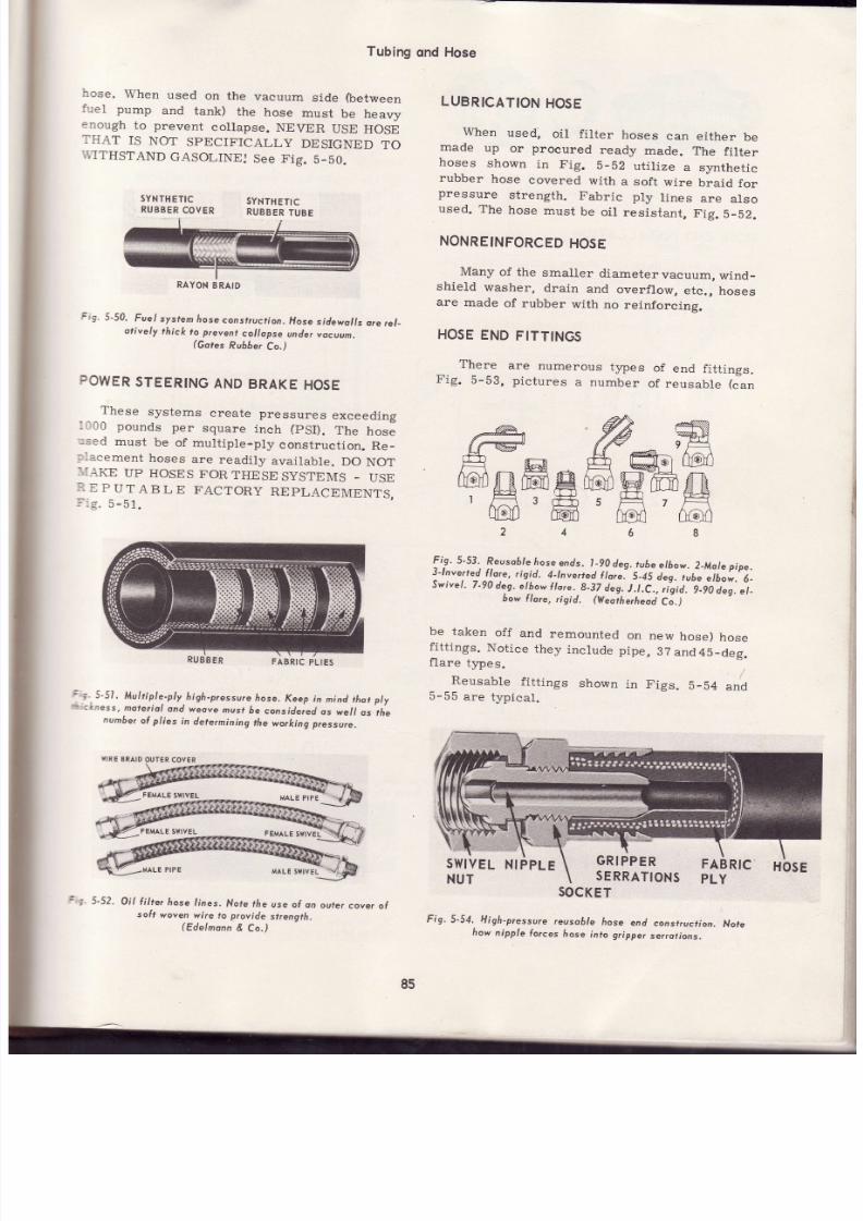
7/26/2019 Auto Service and Repair - Martin W. Stockel
http://slidepdf.com/reader/full/auto-service-and-repair-martin-w-stockel 85/224
Tubing
qnd
Hose
hose.
When
used
on
the
vacuum
side
(between
:':rel
pump
and
tank)
the
hose
must
be
heavy
:nough
to prevent
collapse.
NEVER
USE
HOSE
THAT
IS
NOT
SPECIFICALLY
DESIGNED
TO
,T,ITHSTAND
GASOLINE,I
See
Fig.
5_b0.
LUBRICATION
OSE
When
used,
oil
fí l ter
hoses
can
either
be
made
up
or
procured
ready
made.
The
fi lter
hoses
shown
in Fig.
b-b2
uti l ize
a synthet ic
rubber
hose
covered
with
a soft
wire
braid
for
pressure
strength.
Fabric
p1y
lines
are
alsoused. The
hose
must
be
oi l
res is tant,
Fig.
b_b2.
NONREINFORCED
OSE
Many
of the
smaller
diametervacuum,
wind_
shield
washer,
drain
and
overflow,
etc.,
hoses
are
made
of
rubber
with
no
reinforeing.
HOSE
END
FITTINGS
There
are
numerous
tJ,?es
of
end
fitt ings.
Fig.
5-53,
p ictures
a
number
of
reusable
(can
{@n
# ffi
ffi^ ffm ffi
ftqDñffigtudWffiSR
lF=3¡F+s¡* 'FA
a@il
f f i
hC'ó@d
Fig.
5-53.
Reuso6/e
rose
ends.
t
-90
deg.
ube
elbow.
2-Mole
pipe.
3^-lnve¡ted
lore,
r is id.
4-lnverted
lorel
S-45
.;.; ; ; .
etbow.
6-
Swivel .
7-90
deg.
e/óow
lo¡e..g-37
aeg.
.t.C.,
,ís i j .- l_ lO
a g..t_
bow
llare,
rigid.
(yteo¡he¡heod
Cá.)
'YNTHETIC
UBBER
OYER
SYNTHETIC
RUBBER
UB E
a
g,
5-50.
Fuel
system
rose
consfruction.
Hose
sidewol ls
o¡e
¡el_
otively
thick
fo
prevent
co//opse
unde¡
vocuum.
(Gores
Ruó6er
Co.)
POWER
TEERING
ND
BRAKE
HOSE
These systems create pressures exceeding
--00
pounds
per
square
inch
(pSI) .
The
hose
':sed
must
be
of multiple-ply
construction.
Re _
:-acement
hoses
are
readily
available.
DO
NO T
:.:AKE
UP
HOSES
FOR
THESE
SYSTEMS
-
US E
: .
E
P
UTABLE
FACTORY
REPLACEMENTS,
l -e.5-51.
i . ,5-51
Mul t ip. le.-ply.high-pressure
ose.
Keep
in
nind
thotpl y
.kness,
moteriol
and
weove
musf
óe
conside¡ed
os
we//
os
the
number
l pl ies
n
determining
he
working
pressure.
be
taken
off
and
remounted
fitt ings.
Notice
they
include
flare
types.
Reusable
fitt ings
shown
5-55
are
typical .
on
new
hose)
hose
pipe,37and4b-deg.
/
in Figs.
5-54
and
5-52.
Oi l f i l re¡
áose
l ines,
Nofe the
use ol
on
outer
cover
o(
soft
woven
wire
to provide
strenglh.
(Edelnonn
&
Co.)
SOCKET
Fig.
5-54,
Higl r-pressure
euso6/e
áose
end
consrrucfion,
Nore
how
nipple
fo¡ces
hose
inlo gtipper
se¡rotions.
RAYON
RAID
FABRIC
PLIES
GRIPPER
SERRATIONS
85

7/26/2019 Auto Service and Repair - Martin W. Stockel
http://slidepdf.com/reader/full/auto-service-and-repair-martin-w-stockel 86/224
NU T
Fig. 5-55.
Low-pressure
hose
end const¡uct ion.
Tf ie
spl i t
s /eeve
forces
inside
of
hose ogoinst
nipple.
HOSE
END
INSTALLATION
Fig.
5-56,
detai l
A,
shows
simple
Barbtype.
1. Lubricate
the
hose
and
fitting. DO
NOT
USE
A
LUBRICANT
THAT
WILL
ATTACK
TH E
HOSE
OR CONTAMINATE
THE
SYSTEM:
2.
Shove
hose eompletely
over
barbed
end.
Hose is shoved
against
flat surface
to seat
insert
fully.
4.
Nuts are
pushed
over
insert,
hose shoved
over
nipple
and
nuts tightened.
Fig.
5-56,
detai l
C.
1.
Air brake
hose spring
slid
over
hose.
2. Hose pushed into socket.
3.
Nipple threaded
into socket
squeezing
hose
between
nipple and socket.
See
Fig.
5-54.
4.
Spring
snapped
over socket
shoulder.
Fig. 5-56, detai l
D.
1.
Hose marked
and
skived
(outer
layer of rubber
removed
down
to
first layer of cord).
BE
CAREFUL
NOT
TO
CUT
CORD.
2.
Skived
end
shoved
into
socket.
, w
w*
3
4
E
Fig.5-56.
Generol
methodol
ol toching
vor ious
type
hose ends.
( lnper iol
Bross
Mfg'
Co.)
3.
Remove
by cutt ing
the
hose.
Fig. 5-56,
deta i l
B,
i l lustrates
a compression
fit t ing
used
for
wire braid
hose.
1.
One end
of
the
braid
is
necked
down
and
th e
other
flared.
The nuts
are
installed.
2.
The hose
is installed
over
the
nipple
toadapt
it to
size,
and
is then
removed.
3.
Insert
is
placed over
hose
and
under
braid.
Nipple and
hose lubricated.
Nipple
threaded
into socket.
Fig. 5-56,
deta i l
E.
Hose shoved
into socket.
Mandrel
(pilot
to expand
hose and assist
proper
seating)
lubricated.
3.
Nipple
threaded
in .
4.
Mandrel
seated
and then
removed.
?
4.
1.
2
86
1n

7/26/2019 Auto Service and Repair - Martin W. Stockel
http://slidepdf.com/reader/full/auto-service-and-repair-martin-w-stockel 87/224
Tubing
qnd
Hose
When assembling
hose
ends, always
lubricate
xith
water,
soap, oil,
brake f luid, aircondit ion-
ing
compressor oil or some
other
agent
that
is
compatible with
the system.
Direct ions
given
ior f it t ings in Fig. 5-56, are
general. Always
iollow
the
part icular manufaeturerrs
instruc-
: ions. A
skiving
knife
and
mandrel set are shown
:n Fig. 5-56,A'.
Fíg.
5-56A.
Skiv' ing
kni le ond mondrel sef. These
ore essenfiol
lools for
proper
inslollolion
ol certoin
fype frose
ends.
SKIVED
OSE
As mentioned,
when
instruct ions call
fo r
skiving
a
hose
be careful
not to
cut
the cord.
A
iit t ing using a skived section is shown in Fig.
i-57.
Skive only that
port ion
necessary.
Th e
skived
port ion
should
not
extend
out ofthe
f it t ing.
MOUNTING
OSES
Avoid
sharp or
double bends
and
twist ing as
:his tends
to cause
premature
failure.
In
de -
termining
how
sharp
a hose bend may be,
f igure
Fig. 5-58. Incor¡ec ond correct hose instol lotions, Dou6/e 6ends
ond twistina ore
fo be ovoided.
that the radius
of the bend sháuld
be
AT
LEAST
FIVE TIMES
the outside
diameter
of the
hose.
For
example:
A hose with an
OD
of
1/2 in. should
have a bend
radius of
2- l l2
in.
In
other
words,
i f the
hose were
pul led
around
a
circ le,
th e
cirele
would be
at least 5
in. in diameter.
When making straight
run connections,
allow
some slack
to
avoid
stressing
the hose
from
pressure,
vibrat ion
or
part
shif t ing.
When
tightening
hose f it t ings, t ighten
th e
swivel end last. Always support one port ion
with one
wrench while t ightening
with another
to
prevent
twist ing
the hose.
Use f lare
wrenches.
Fig.
5-58,
i l lust rates
some
typlcal hose
in-
stallat ions.
Those in the left
column
are
WRONG.
The
correct
methods are
shown
inr ightcolumn.
Notice
how single, smooth
bends,
without
twÍst-
ing
are
made,
Fig. 5-58.
RIGH
4
5
@-.:rEb
ÍFC--Eotr
]F
Ff
ñ
K
E
ñ
u*
A
HÉ
W
Éfi
U
ru
hÉ
U
,re
q
ñ
:
f ]Fc
lll= )
(
Hii l
V
OUTER
AYER
REMOYED
SKIVED)
FABRIC
PLIES
RUBBER
LAYER
F
g.
5-57,
Permonenl
no¡
reusoble)
oseend.Note skivedsection.
87
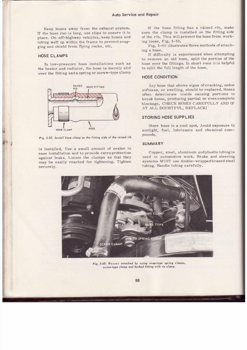
7/26/2019 Auto Service and Repair - Martin W. Stockel
http://slidepdf.com/reader/full/auto-service-and-repair-martin-w-stockel 88/224
Auto
Service
ond
RePoir
Keep
hoses
away
from the
exhaust
system.
If the
hose
run
is long,
use
clips
to secure
it
in
plaee. On off-highway
vehicles, keep
hoses
an d
tubing
well up
within
the
frame
to
prevent snag-
ging
and
shield
from
flying
rocks,
etc.
HOSECLAMPS
In low-pressure
hose
installat ions
such
as
the
heater and
radiator,
the
hose
is merely
sl id
over
the
fit t ing
and
a spring
or
screw-type
clamp
\
I f the
hose
fit t ing
has a raised
rib, make
sure
the clamp
is
installed
on
the
fit t ing side
of
the
rib.
This will
prevent
the
hose
from
work-
ing loose,
Fig.
5-59.
Fig.
5-60
illustratesthree
methods of
attach-
ing a
hose.
If dif f iculty
is experienced
when
attempting
to remove an old hose, split the port ion of the
hose over
the
fit t ings.
In
short
runs
it is helpful
to split
the
ful1 length
of the
hose.
HOSE ONDITION
Any hose
that shows
signs
ofcracking,undue
softness,
or
swelling,
should
be
replaced.
Hoses
often
deteriorate
inside
causing
portions to
break
loose,
producing
part ial
or
evencomplete
blockage.
CHECK
HOSES
CAREFULLY
AND
IF
AT ALL
DOUBTFUL,
REPLACE.I
STORING HOSE SUPPLIES
Store
hose
in
a cool
spot.
Avoid exposure
to
sunlight,
fuel,
lubricants
and chemical
com-
pounds.
SUMMARY
Copper,
steel, aluminum
andplast ictubingis
used
in automotive
work.
Brake
and
steering
systems
MUST
use
double-wrappedbrazed
steel
tubing.
Handle
tubing carefully.
HOSECLAMP
Fig.
5-59.
nstoll
hose
clamp n
the
itt ing
side
oÍ
the
oised ib'
is
installed.
Use a smatl
amount
of
sealer
to
ease
installat ion
and
to
provide extraprotection
against
leaks.
Locate the elamps
so
that
they
may be
easily
reached
for
t ightening.
Tighten
securely.
Fig.5-60.
Hoses
attoched
by
using
snop-fyPe
spr ing
clomps,
screw-type
clomp
ond borbed
Íitting
with no clomp'
88
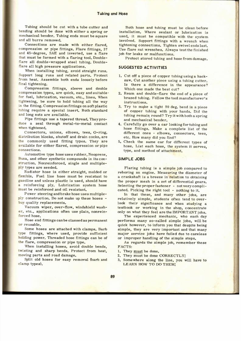
7/26/2019 Auto Service and Repair - Martin W. Stockel
http://slidepdf.com/reader/full/auto-service-and-repair-martin-w-stockel 89/224
Tubing
ond
Hose
Tubing
should
be
cut with
a tube
cutter and
bending
should
be done
with
either
a
spring
or
mechanical
bender. Tubing
ends
must
be
square
and
all
burrs
removed.
Connections
are made
with
either
flared,
compression
or
pipe
fittings.
Flare
fitti.ngs,
3Z
and
45-degree,
SAE
and
inverted,
use a
flare
üat must be forrned with a flaring tool. DoubLe-
llare
all double-wrapped
steel
tubing.
Double-
flare
all high
pressure
applications.
When
installing
tubing,
avoid straight runs.
Support
long
runs and related
parts.
Protect
from
heat.
Assemble
both
ends loosely
before
final
tightening.
Compression
fittings,
sleeve
and double
compression
t¡pes,
are
quick,
easy
andsuitable.
lor
fuel,
lubrication,
vacuum, etc.,
lines. When
Cghtening,
be
sure to hold tubing
all the way
:¡r
the
fitting.
Compression
fittings
on
soft
plastic
*bing
require
a special insert.
Both
standard
and long nuts are available.
Pipe
fitt ings
use a tapered
thread. Theypro-
duce
a seal through
metal-to-metal
contact
rhen
tightened.
Connectors,
unions,
elbows, tees,
O-ring,
Cistribution
blocks,
shutoff
and
drain
cocks, are
the
commonly
used fitting t)pes.
They
are
available
for
either
flared,
compression or
pipe
connections.
-{utomotive
t¡pe hose uses
rubber,
Neoprene,
Buna,
and
other synthetic
compounds in its
con-
struction.
Nonreinforced,
single and multiple-
ply types
are needed.
Radiator
hose is
either straight, molded
or
flexible.
FueI
line
hose must be
resistant to
Easoline
and unless
plastic
is
used,
should
have
a
reinforcing ply.
Lubrication
system hose
nust
be
reinforced
and
oil resistant.
Power
steering
and brake hose
uses multiple-
Flv
construction.
Do
not make
up these hoses
-
buy quality
replacements.
Vacuum
wiper,
over-f low, windshield wash-
er,
etc.,
applications
often use
plain,
nonrein-
iorced
hose.
Hose
end
fitt ings
canbe
classed as
permanent
or
reusable.
Some hoses
are attached with
clamps.
Barb
type fittings, where used, provide sufficient
holding power.
Threaded
hose fittings
can
be of
the
flare,
compression
or
pipe
t¡pe.
When
installing
hoses,
avoid double bends,
twisting
and
sharp bends.
Protect
from heat,
noving parts
and
road
damage.
Sllit
old hoses for
easy removal
(barb
and
clamp
types).
Both
hose
and tubing
must
be
clean before
installation.
Where
sealant
or lubrication
is
used, it
must
be
compatible
with
the-
system
involved.
Support
fitt ings
with
a wrench
when
tightening
connections. Tighten
swivel
ends
last.
Use flare
nut wrenches.
Always
testthe finished
job
for
leaks
or malfunctions.
Protect stored tubing and hose from damage.
SUGGESTED
CTIVITIES
1. Cut
off
a
piece
of
copper tubingusinga
hack-
saw. Cut
another piece
using a tubing
cutter.
Is
there
a
difference
in
the
appearance
?
Which
one
made
the
best
cut?
2. Ream
and
double-flare
the
end
of a
piece
of
brazed
tubing. Follow
the
tool
manufacturerrs
instructions.
3.
Try
to
mqke
a tight
90
deg.
bend in
a
piece
of
copper
tubing
with your
hands. Did
th e
tubing remain round ? Try i t wi th both a spring
and mechanical
bender.
4.
Carefully go
over a
car lookingfortubingand
hose
fittings.
Make
a complete
l is t
of the
different
ones
-
elbows,
connectors,
tees,
etc. How
many
did
you
find?
5.
Check
the
same
car
for
different
types
of
hose.
List
each
hose,
the
system
it
serves,
type,
and method
of
attachment.
SIMPLE
JOBS
Flaring
tubing is
a
simple
job
compared
to
reboring
an engine. Measuring
the diameter of
a
crankshaft is
a breeze in
relation
to
obtaining
the proper
mesh
in
a set
of differential gears.
Selecting
the
proper
fastener
-
not very
compli-
cated.
Picking
the right
tool
-
nothing
to
it .
In
that
these,
and many
other
jobs,
are
relatively
simple,
students
often tend
to
over-
Iook their
significance
and
when
studying
a
textbook
or working
in
the
shop,
concentrate
only
on what
they feel
are
the
IMPORTANT
jobs.
The
experienced
mechanic, who
each day
performs
many so-called
simple
jobs,
witl be
quick
however,
to
inform
you
that despite
being
simple, they
are
very
important
and that many
major service jobs have failed
due to
careless
or improper
handling
of the
simple steps.
As
regards
the
simple
job,
remember
these
FACTS:
1.
They
must
be done.
2.
They
must
be done CORRECTLY:
3. Somewhere
along the
line,
you
will
have to
LEARN
HOW TO
DO THEMJ
ii
li
t¡
ir :
5
89

7/26/2019 Auto Service and Repair - Martin W. Stockel
http://slidepdf.com/reader/full/auto-service-and-repair-martin-w-stockel 90/224
AutoService
ond
Repoir
Keep
this
in mind as
you
studythis
and other
texts.
Read EVERYTHING
carefully
and consider
EVERYTHING
you
read
IMPORTANT.
You will
be
glad you
didl
OUIZ
-
ChoPter
1, Tubing is widely used in automobiles. True
or
False?
2.
The
two
most
commonly
used tubing
ma -
terials are-and-.
3.
When
removing
tubing
from
a
ró11, lay
the
roll
flat
on
the bench and
pull
the free end
upward.
True
or
False?
4.
The
more tubing
is
worked,
the softeritbe-
comes.
True
or
False?
5. Double-wrapped,
tin-plated
brazed steel
tubing
is
suitable
for
brake line
work.
True
False ?
Plastic
tubing
cannot
be used
for any auto-
motive work. True or False ?
A-
-is
ideal
for
cutt ing
tubing.
After
cuttrng, remove-and
while doing
this,
hold the
tubing end-.
To
make sat isfactory connections,
tubing
must
be cut_.
Always
-double-wrapped
steel
tubing.
11.
What
are two
flare
angles?
12.
What is
the
first
forming step
called
when
making a double-lap
flare?
As long as
the f lare is the correct
angle,
it
can
be slight ly cocked
to
one side.
True
or
False ?
The_should be
placed
on
the tube
be -
fore flaring.
15.
Tubing
can best
be bent
by using either
a
-or
a-bender.
16. A
few
particles
of dirt,
metal, etc.,
as long
as
they are small,
can
be left
in the
tubing
without harm.
True
or
False ?
1?. Straight
runs of
tubing shouldbe
made
when-
ever
possib le. True
or
False?
18.
When install ing, connect the-legfirst.
19.
If
you
force
fittings that start
hard,
youwill
-thread
them.
20. When
fi tt ings
are
properlyaligned,
theymay
be
given
turns
byhandbefore
a
wrench is needed.
21. When making long tubing
runs, be
certainto
-the
tubing.
22.
Always
use
_to
tighten
tubing
fi ttings.
23. What is the
basic d i f ference
betweenanSAE
flare
and an
INVERTED
flare fitting?
24.
Tubing
bends
should start at least_
of the fitting nut from
the actual
connection.
25.
Brake
line
and
power
steering tubing shouÍd
26.
Name
two t¡pes of
eompression
fitting.
27. Compression fittings are generally used
where_pressures
are
encountered.
28. When
using a sleeve
compression
fitting
on
soft
plastic
tubing,
an_is necessary.
29.
On
a flare fitting,
after bringing the nut
up
solidly, how much more
of a
turn
of
the
wrench is
requi red?
30.
On
new
compression
fittings,
how much
should the wrench
be turned
afterthe sleeve
grasps
the tubing
-
for
ll8
-
|
/4
in. for
5/16 in .
and
for
3/B to
1
in.?
31. After f i rm
hand tightening, how many turns
are
necessary for
pipe
fittings
?
32. The_compression fitting WILL handle
high
pressure.
33.
As
opposed to the standard nut, the
long
nut
provides
better resistance to_.
34.
Install
drain
cocks so that the
confinedfluid
rests against the_and not
the_.
35.
Pure
rubber hose would make
a
fine fuel
l ine
connection.
True
or
Fa1se?
36.
Name
three
basic types of radiator hose.
37.
Double
bends
will
prolong
the life
of
hose.
True
or
False
?
38.
Brake
hoses
are of_plyconstruction,
39. It is
not necessary
to secure long runs of
hose. True or Fa1se?
40.
Barb
type hose fittings
use clamps.
True
or
False
?
41. What is
meant by
skiving a hose?
42.
In
determining
how
sharp a
bend
a
hose
shoul.d be subjected to, what handy
rule
would
you
use
?
43. If
a
hose Looks
good
on the
outside,
it wil l
surely be
good
on the
inside. True
or
False?
44. A
small amount of
_will
make
radiator
hose insta l la t ion
easier and wi l lhe lptopre-
vent
seepage.
45.
Describe
three types of
hose
clamps.
46.
Hose
should be stored
in
a
warm dry area.
True
or
False ?
be
n
il
7.
'
'i r
iri.
9.
1l
' '
10.
13.
1^
r
l
ii
i
i
^n
48 .
49.
When tightening
hose
or
tube
fittings,
always
-the
fitting body while tightening the
nut.
Tighten the_end of the
hose
lást.
The word
DRYSEAL refers
to
a
special
pipe
thread sealer.
True
or
False
?
90

7/26/2019 Auto Service and Repair - Martin W. Stockel
http://slidepdf.com/reader/full/auto-service-and-repair-martin-w-stockel 91/224
50.
Study the following
drawing
of a theoretical
tube
installation.
All fittings
are
missing.
Can
you
name the
correct
fitting
for
each
c onnection ?
A list is
provided.
Some
are needed,
some
are not.
Write down
the number
of eachmissing
fitting
and directly
opposite
it write
the name
of the
fitting you
have
chosen to use.
Mcle
Run
fee.
Femole 45 deg.
Elbow.
Femole
Run fee.
Distri6urion Bloc/<.
Mole 45 deg.
Elbow.
Mole
Connecto¡.
Tubing
qnd
Hose
Femole
Conneclor.
Union
Cross.
Femole Broncfi Tee.
Bulkheod Union.
Stroight Union.
Mole
Double
90 de7.
Elbow,
Femole
Double
90
deg.
Elbow.
45
deg.
Street Elbow,
Pipe
Coupling.
Mole 90 deg. Elbow.
Mole
8¡oncfi
lee.
Union
Tee.
PIPE
E
(J ',,
\ \@
Ai
%Nff i
@)
ñr.
v
tt*l
r--ll -l
' r l l
l l
-
l i l i lá
ill il:
UJ
[=l
\#/
\I-L--l
A
Fig.5-61. l .S.O.
rype
of l lare is
sñown in
A.
B
and
C
depict
vorious
fiose litting mounting
Ílange sáopes.
(Chev¡olet)
Y)'
q
9l

7/26/2019 Auto Service and Repair - Martin W. Stockel
http://slidepdf.com/reader/full/auto-service-and-repair-martin-w-stockel 92/224
Auto
Service
ond
Repoir
Longi tudinol
secf iono/
v iew of
Fiot
4-cylinder
overf ieod
camshoh engine.

7/26/2019 Auto Service and Repair - Martin W. Stockel
http://slidepdf.com/reader/full/auto-service-and-repair-martin-w-stockel 93/224
Chapfer
6
WIRE
AND
WIRING
New
wiring,
properly
installed, is
relatively
trouble
free but
as the
car ages the
wires
tend
to
deteriorate from
exposure to heat,
oi1,
gas,
fumes,
acid, vibration,
etc. Vehicles
damaged
by
coll is ion or
fire
often
require
extensive re-
wir ing. The
auto mechanic
shouldbecomefamil-
iar
with
types of
wire,
sizes,
insulation,
con-
nections
and
general
installation
procedures.
PRIMARY
WIRE
The primarywir ing
handlesbatteryvoltage
-
6,
12 and in
some commerc ia lvehic les,24vol ts .
It
has
sufficient insulation
to
prevent
current
loss at these
voltages. All wir ing
circuits inthe
car, with
the exception of
the
ignition
high ten-
sion
circuit, use
primary
wire. NEVER
US E
PRIMARY
WIRE
FOR
SPARK
PLUG
LEADS.
SECONDARY
IRE
Secondary
wire
is
used i n the ignition sys-
tem high tension circuit - coil to distr ibutor,
distr ibutor
to
plugs.
I t
has
a
heavy
layer of
in-
sulation
to
afford
protection
against excessive
corona
(loss
of electrons to the
surrounding
air)
which
could impart suffi.cient
current
into
an adjacent wire
to cause it to
f i re
a
plug. This
action
is known
as cross-fir ing.
Even
with
good
insulation
i t
i.s important to
arrange spark
plug
leads
so that
leads to
cylinders
that fire
con-
secutively
are
separated.
Fig.
6-1,
shows the
relative
difference in
the amount of insulation
on
primary
and secondary wires.
STRANDING
t
PRIMARYWIRE
STRANDING
ATERIAL
Sof t
copper is
widelyusedforwi re
st randing.
It
is
an excellent
conductor, bends
easily and
solders readily.
Aluminum also
is
employed to
some
extent.
Copper,
sta in less steel , carbon
impregnated
thread
and elastomer
type
con-
ductors
are used for
secondary wire stranding.
The carbon impregnated
thread and
elastomer
type
(Duoprene
G,
for
example) impart a
con-
trol led
resistance
(about
10,000 o 20,000
ohms
per
foot)
in
the secondarycircuitto
reduce
radio
interference.
WHEN WORKING ON THE IG-
NITION
SYSTEM, HANDLE
RESISTANCE TYPE
HIGH
TENSION
WIRES CAREFULLY.
SHARP
BENDING
AND
JERKING
ARE
APT
TO
SEP-
ARATE
THE
CONDUCTOR,
THUS
RUINING THE
WIRE.
WHEN REMOVING OR
INSTALLING
SUCH LEADS,
GRIP THE INSULATION
BOOT
-
NOT THE
WIRE:
Resistance
t¡rye wires
may
be identif ied
by
such
letters
as
IRS,
TVRS,
etc.
Automotive wiring uses stranded (conductor
made
up
of a number
of small
wires twisted
together)
conductor .
wlRE tzE
Each
conductor size
(do
not
count the thick-
ness
of
the
insulation)
is
assigned a number.
The
larger
the number ,
the smaller
the wire.
The
Ameriean
or Brown
and
Sharpe wire
gauge,
is
the
commonly used
standard for
wire
s ize;
To
find
the
gauge
of a
solid wire,
simply
measure
it with
a
micrometer
and locate
this
answer or nearest one, on a wire gauge chart.
Moving
across to the wire
gauge
column, de-
termine
the
correct
wire
gauge.
To find
the
gauge
óf a stranded
conductor,
count the
number
of strands.
With
a microm-
eter, measure
the diameter
of
ONE
strand.
Square this
answer
and
multiply
by the number
of
strands.
This
wi l l
g iveyouthecross
sect ional
ig.6-1. More nsulotion s
reguiredon
secondory
wires.
93
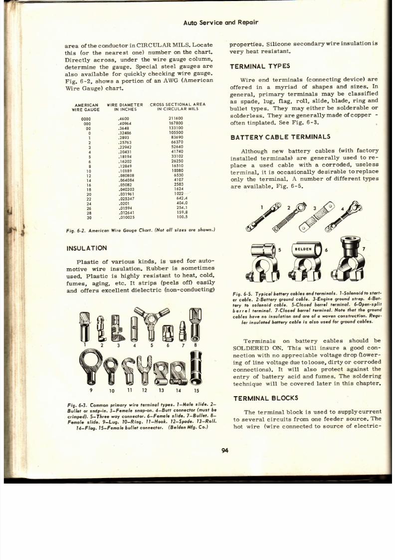
7/26/2019 Auto Service and Repair - Martin W. Stockel
http://slidepdf.com/reader/full/auto-service-and-repair-martin-w-stockel 94/224
Auto
Service
ond
RePoir
area of
the conductor
in CIRCULAR
MILS.
Locate
this
(or
the
nearest
one)
number
on the
chart.
Directty across,
under
the
wire
gauge
column,
determine
the
gauge.
Special
steel
gauges
ar e
also
available
for
quickly checking
wire
gauge.
Fig.
6-2, shows
a
portion
of
an
AWG
(American
Wire
Gauge)
chart.
AMERICAN
WIRE DIAMETER
CRO55
sECTIONAL
AREA
WIRE GAUGE
IN INCHES
IN'CIRCULAR
MILS
properties.
Silieone
secondarywire
nsulation
s
very
heat resistant.
TERMINAL
TYPES
Wire end
terminals
(connecting
device)
ar e
offered
in a
myriad
of shapes
and sizes.
In
general, primary terminals may be classified
as
spade,
lug,
flag, ro11, slide,
blade,
ring
and
bullet
t¡pes.
They
may either
be
solderable
or
solderless.
They
are
generallymade ofcopper -
often
tinplated.
See
Fig. 6-3.
BATTERY
ABLE
TERMINALS
Although
new battery
cables
(with
factory
installed
terminals)
are
generally used
to re-
place
a
used cable
with
a corroded,
useless
terminal,
it is occasionally
desirable
toreplace
only
the
terminal.
A number of
different types
are available, Fig. 6-5.
='99'
tert
Fig.
6-5. Typicál
battery
cobles
ond te¡minols.
l-Solenoídfo
stort-
e¡
coble.
2-Bottery
ground
cable. 3'Engine
ground
strop'
4-Bot-
tery fo solenoid
coble. S-Closed
bo¡rel
terminol. 6'Open'split
bor¡el
lerminol ,7-Closed
bonel
te¡minol '
Nore
f lot the
ground
coóles
[ove
no insulolion
ond are of
o woven
conslrucfíon.
Regu-
lor insuloted
batlery
eoble
is olso
used
lor
ground
cohles'
Terminals on
battery cables
should
be
SOLDERED
ON. This will insure
a
good
con-
nection
with no appreciable
voltage
drop
(lower-
ing
of
line voltage
due toloose,
dirty or corroded
connections).
It will also
protect
aga,inst
th e
entry
of
battery
acid and
fumes.
The soldering
technique
will be
covered
later
in this
chapter.
TERMINAL
LOCKS
The
terminal
block
is used
to supplycurrent
to several cireuits
from one
feeder
source.
Th e
hot
wire
(wire
connected
to source
of electric-
0000
.4ó00
000
.40964
00
.3648
0
.32486
1 ,2893
2 .25763
3
.22942
4
.20431
5 . l8l94
6 ,16202
I
.12849
l0
.10189
12
.080808
t4
.0ó4084
ló .05082
I
8
.040303
20
.0319ól
22
.025347
24
.020t
26
.01
94
28
.012641
30 .01
02 5
2l ló00
ró7800
133100
I 05500
83ó90
66370
52640
41740
Q?l n?
262s0
I ó5',I
I 0380
ó530
4107
2583
1624
1022
642.4
404.0
254.1
I
59.8
I 00.5
Fig.
6-2.
Ame¡icon
Yl i re Gouge
Cho¡¡-
Not
ol l s izes
ore sf iown')
INSULATION
Plastic
of
various
kinds,
is used
for' auto-
motive
wire
insulation.
Rubber
is sometimes
used.
Plastic
is
highly
resistant
to
heat, cold,
fumes,
aging,
etc. It
strips
(peels
off)
easily
and offers
excellent
dietectric
(non-condueting)
ffiffiffiMeW
WWNWNNE
Fig. 6-3'
Comnon
pr imory wire te¡minol
ypes. I -Mole
sl ide. 2-
Bitlet
o¡
sndp-in. 3-Femole
snop'on. 4-Butt
connectot
(must
be
crimped), 5-Tfi¡ee
woy connector.
6-Female
slide. 7-Bullet.
8-
Femole
sl ide.
9-Lug.
t l -Ring.
l l -Hook.
l2-Spode,
l3-Rol l .
l4-Flog.
l5-Fenole
bul lef
connecfor.
(Belden
Míg. Co')
l5
4
3
2l
0
94
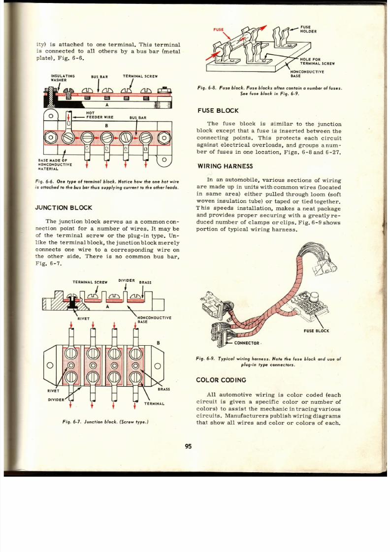
7/26/2019 Auto Service and Repair - Martin W. Stockel
http://slidepdf.com/reader/full/auto-service-and-repair-martin-w-stockel 95/224
: ly)
is
attached
:s
connected to
:1ate) ,
Fig. 6-6.
INSULATING
WASHER
to
one terminal.
This
terminal
all
others by
a bus bar
(metal
TERMINAL
SCREYI
BUSBA R
EASE
MADE
NONCON
UCTIVE
MATE
RIAL
Fig.
6-6,
One
type
ol te¡minal6/oc/<.
Norice
how t/re one hot
wire
is ottocfred o fhe 6us bor lhus supplying cuilent to t/re other leods.
JUNCTION
LOCK
The
junct ion
block
serves as
a commoncon-
nection
point
for
a number
of
wires. I t
may be
of the terminal
screw
or the
plug-in
type.
Un -
like
the
terminal block,
the
junct ion
block merely
connects
one
wire
to a
corresponding
wire
on
the
other side.
There
is
no common bus bar,
Fig.6-7.
DIVIDER
HOLE
FO R
TERMINAL
SCREVI
NONCONDUCTIVE
BASE
Fig. 6-8.
Fuse
ó/ock.
Fuse
ólocks
often contoino
number f
fuses.
See use block in Fig.6-9.
FUSE
BLOCK
The
fuse
block is
similar
to the
junct ion
block
except
that a fuse is
inserted
between
th e
connecting
points.
This
protects
each
circuit
against
electr ical
overloads,
and
groups
anum-
ber
of
fuses
in
one locat ion,
Figs.
6-8and
6-27.
WIRING
HARNESS
In
an
automobile,
various sect ions
of wir ing
are made up in units withcommonwires (located
in
same
area)
either
pulled
through
loom
(soft
woven insulat ion
tube)
or taped
or t ied
together.
This speeds installat ion,
makes
a neat
package
and
provides
proper
securing
with
a
greatlyre-
duced
number
of c lamps
orc l ips.
Fig.6-g
shows
port ion
of typical
wir ing harness.
Fig.6-9.
Typicol
wir ing
Áorness.Nole fhe
fuse block ond
use of
plug-in
type
connectors.
COLOR
ODING
A11
automotive
wiring
is
color
eoded
(each
circuit is
given
a
specif ie color
or
number
of
colors) to
assist the
mechanic intracing
various
circuits.
Manufacturers
publish
wiring diagrams
that
show all
wires and color
or colors of each.
BA RU5
, l
a
:
,
f
{
I
:
,t
,
a
:l
1
rt
i,
,.
¡
i
Fig. 6-7. Junction 6loc/<.
Screw
ype.)
95
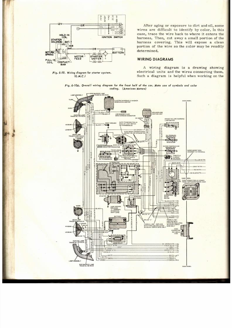
7/26/2019 Auto Service and Repair - Martin W. Stockel
http://slidepdf.com/reader/full/auto-service-and-repair-martin-w-stockel 96/224
f ig.
6-10.
Vl i r ing
diagrom
or
stor lersystem.
lG.M.C.)
After
aging or exposure to dirt
and oil, some
wires
are diff icult
to identify by
color.
In
this
case,
t race the wire
back
to
where
it
enters the
harness. Then,
cut away a small
port ion
of the
harness
covering.
This
wil l expose
a clean
portion
of the
wire
so the
color
may be readily
determined.
WIRING
DIAGRAMS
A wiring diagram
is
a
drawing
showing
electrical
units and the
wires
connecting them.
Such a diagram is helpful when
working
on the
F¡g,
6-10A.
Qverol l
wir ing diogrom for the l ¡ont
hol{ o{ ¡he
cor.
f . fole
use ol sym6ols ond
colo¡
coding,
(lmericon
llotors)
]
*
EL€CT RIC
WINOSHIELD
WASHER
WIRE HARNESCONÑ€CTOF
AUTO TRANSNEUTFALA
BACK UP
LIGHTSWITCH
r::l
I
rffi:
Í6
I 1 or lPFEssuFE
d
;-(JmE$toN
8ac(uP
I
)A?ACIIOFCONNECTOR
TS
ON
:¡:::.=ffi==
sr¡¡r¡a
F:*w:t*q
LJ
WAÍER fEMPERATURC
GROMMEf IN FIREWA L
llltffii
lffil
L".o"*
*rr"_o.
THI+HL
| 145#$ii=ii,
I
'i]'#ffi:
+:-'[
l"l"Fffi:iilq{i,, I
I
il,;iüá"'
ff_Vüfi_*...*,fi_]:__l"l;-31 |
I# ; ""17=ffiil*;."
=
:
i
¡r"Ul:'*:i;l*'*tsi'i'"r 1t"l"1xti"Hf
Éffirri-
""'t;{i-HJL
r;-nL---Jt ¡r | |
-€t :#
i l | |
L--- 9 4I--J
I
-V|OLET
w/TR-vtOLET
w[R_aZ
I
-GBAy-cRAy-ar
I
K GBEEN-OK
GREEN-AY
I
BROWNWrTA-AROWN W TR-3x
I
(
BLUE
DK 8LUE-CZ
I
-.
Wiil:7'"
1
LrGñEEN-| ISIEEI: . ,
I

7/26/2019 Auto Service and Repair - Martin W. Stockel
http://slidepdf.com/reader/full/auto-service-and-repair-martin-w-stockel 97/224
Wire
qnd
wiring system.
As
mentioned,
wiring
diagrams
are
available
in
various
shop
manuals
and
in
some automotive
reference
type
books.
Use
themi
Fig. 6-10, shows
a
typicalwiringdiagram
for
a speeifie
unit.
The modern auto
electrical
system
is becoming
more complicated
each
year. Many
manufacturers
break
down
the
various circuits into separate diagrams, (Fig.
6-10),
as
well as
providing an overall
diagram
showing the
entire
electrical
system.
Fig.
6-10A
shows
an overall
diagram
for the
front
half
of
the auto.
See
Figs.
6-10 and
6-104-
ELECTRICAL
IRING
YMBOLS
There is a
wide variation
in
the use
of auto-
motive electrical
symbols.
Some
companiesuse
their
own
drawings
for sorne
units and
standard
symbols
for others.
The
units
basic
internal
circuit
is
sometimes
shown
and
in other
dia-
grams, symbols are used for all units. Fig.
6-108,
il lustrates
a
number
of
typical
symbols
widely
used
in automotive
electri ial
diagrams.
SELECTINGORRECT
IRE
GAUGE
Line
voltage,
electrical
load and
wire length
are
the
three
important
factors
in
determining
correct
wi re
gauge
or s ize.
Keep in
mind
the
fact that
as
wire
length
INCREASES, resistance
(with
resultant
voltage
drop)
INCREASES.
Resistance
causes
the con-
ductor to
heat.
Excessive resistance
can
heat
i t
to
the
point where
the
insulation
will
melt and
the wire
burn.
As wi re
size
INCREASES,
resistance
DE-
CREASES.
A
simple
rule
then
would be
to state
:hat
to
prevent high
resistance
andvoltage
drop,
rvire
size
must be
increased
as
length
is
in -
creased.
It is obvious
then,
that
with
a
given
voltage
and
load,
a
wire
20
ft. Iong
must
be of a
Iarger
gauge than
one
2
ft. long;
The electrical
load
imposed
on
a
wire
is
merely the sum
of
the
individual
loads
of each
unit
serviced
by
that
wire.
Common
automotive
system
voltage
is now 12
volts.
Some com-
mercial vehicles
use
24v.
Most
carrs
produced
a
number of years ago used 6v. systems.
Most wire
manufacturers
furnish charts,
simi lar to
that shown
in
Fig. 6-11,
to assist
the
mechanie
in
proper
gauge
selection.
To
us e
the
chart
shown,
determine
the
total length
of
the wire needed.
The wire lengths
shown
in the
chart are
for
a single
wire
ground
return
(n o
Fig. 6-108. Electr icol
sym6o/s
commonly
sed in oulomofive
ing diograms.
wire needed
from the
unit as
the
frame or
metal
parts
of
the ear
act as
a return
ground wire).
I f
install ing a
two-wire
circuit
(one
wiré
to the
unit and
another
from the
unit to
ground), count
the length of
both
wires.
Next
compute
the total electr ical load to
which
the
wire witl be subjected.
Be
certain
to
figure the load
of
ALL units
concerned.
If the
load
will fluctuate,
use
the
peak
load
figure.
The
load
may be
figured in
AMPERES,
WATT-
AGE
or
CANDELA-
(Candel.a
is the
international
term
for
candlepower.)
W
ring
^
IRCUIT
BREAKER
?
RHEOSTAT
++
wlRES
CROSStNG-
NOT CONNECTED
rvtREsRosslNG.
CON ECTE
(rdrh)
\¡_,
LAMP.DOUBLE
F
LAMENT
f r ¡n l
u.v
LAMP
SINGLE
FILAMENT.
NsULATED
LAMP-SINGLE
FI
LAMENT.GROUN ED
-4-
TE RMINAL
-*-
SPLICE
4>
swtTcH
I
.<
ts
PUSH.PULLSWITCH
i l
GROUND
{AAr
RESISTOR
¡<
CONTACTPOINTs
-
FEMALE
PU5H.ON
CONN CTOR
MALE PUSH.ON
CONNECTOR
foooo
JUNCTION
BLOCK
-rTdfor
INDUCTIVE
RE5ISTAN E
-l
t t t t t+
. | lr lr l l l | l | l-
BATTERY
I2 VOLT
DIOD
ZENOR DIODE
-
<-
SPARK
GA P
_o-
;F
2 WIREMALE
PUSH.ONCONNECTOR
n
trft
Y
STARTE
GENE AT
TRANSISTOR
PUSH.ON
CONNECTOR
*re
SPRING
SWITCH
r-T-r
--a
(u
(Df
-
OLENOID
WITCH
i
]
r
i
*
*
CONDENSER
la
t \
FIXED
CAPACITOR
VARIABLE CAPACITOR
NEGATIVE
-L
POStTIVE
:
J
1
INDUCTION
OI L
97

7/26/2019 Auto Service and Repair - Martin W. Stockel
http://slidepdf.com/reader/full/auto-service-and-repair-martin-w-stockel 98/224
When
the
load is
determined,
look
on the
chart
under the
correct
voltage
column for
the
nearest
listed
load.
Move
across
the
charthori-
zontally
until
under
the nearest
listed footage.
This
will give
you
the recommended
gauge.
For
example,
say
you
have
a l2v. system,
a
computed
electrical
load
of 20
ampereb
and
a
wire length of 15 feet, Locking on the chart you
will
f ind
the
recommended gauge
to be
No.
14.
For
the
same
load and
length
butwitha
6v.
sys-
tem,
the
recommended
gauge
is
10.
You
will
not ice
that
a 12v.
system
uses
a smaller gauge
wire
than
a
6v.
system.
Using
a l .arger
gauge
than necessary
will
cause no
part icular
harm
unless
the
wire
being
replaced MUST
produce
a
specific resistance
in
the
ci rcui t ,
F ig. -6-11.
Auto
Service
qnd
Repq¡r
CORRECT
STYLE
Fig. 6-12.
Some
common
e¡rors.in terminol
selection.
SELECTING
ROPER
ERMINALS
After
the wire gauge
is
determined,
select
the
proper
size
and t¡pe
terminal.
The
terminal
selected
must
be
suitable for
the unit
connecting
post
or
prongs.
It
must have
sufficient
current
carrying
capacity
and
should
be heavy
enough
to prevent breakage through normal wire fLexing
and
vibrat ion. Fig.
6-12,
shows
some
common
errors
in
terminal
selection.
Arrange
terminals
so they
have
clearance
from
metal
parts
that
could
ground
or
short
them
out. On
critical
applications
or where
heavy
vibration
is
present,
use
a terminal
such
as the
ring
t¡pe
that
eompletely
encircles
the
post.
In
the
event it
loosens,
the wire
will
not
fall
off.
0. 5
1. 0
t. 5
2. O
2. 5
J.J
4. 0
5. 0
5i 5
ó. 0
9. 0
l0
tl
12
l5
20
25
75
10 0
1. 0
t. J
2
4
5
ó
l0
ll
12
IJ
20
22
21
30
,t0
50
t0 0
15 0
20 0
10 8
12 0
t3 2
11 1
6
12
21
3ó
18
ó0
12
l8
24
3ó
51
ó0
66
3
8
l2
l5
20
25
JJ
10
15
óo
70
80
90
10 0
ó
t8
'ro
t8
ló
l8
21
l8
30
t8
10
t8
50
t8
ó0
't 8
70
l8
80
t8
90
't 8
100
l8
120
t8
140
l8
lóo
t8
r80
t8
200
*t
8
l8
t8
tó
t2
t0
lo
l8
t8
l8
l8
ló
11
t4
t1
t2
t2
12
t2
to
to
't 0
I
8
ó
ó
6
2
I
o
l8
l8
't 8
l8
ló
ló
ló
t1
11
't 2
l2
t2
l0
to
lo
't 0
l0
6
ó
1
2
I
t8
l8
l8
t8
t8
l8
t6
tó
tó
t1
11
11
t2
t2
lo
lo
t0
to
8
8
1
2
2
't 8
t8
I8
l8
t8
't 8
tó
't ó
ló
't ó
t1
t1
t2
t2
l0
to
lo
l0
I
8
I
2
2
t8
t8
I8
't 8
t8
't 8
¡8
l8
ló
ló
tó
¡ó
t1
t1
12
t2
t2
t0
t0
to
6
1
4
l8
l8
t8
l8
t8
l8
t8
t8
l8
't 6
l6
ló
l1
t1
l4
t2
12
l0
't o
to
6
I
1
8
t8
t8
l8
l8
t8
t8
't 8
l8
l8
l8
t8
l8
ló
ló
ló
ló
l, {
t2
t2
to
I
6
t8
l8
tó
t1
t2
12
t0
t0
to
¡o
8
8
I
8
6
6
6
1
2
2
0
oo
1/o
l8
l8
ló
t1
t2
l2
t2
lo
'1 0
t0
t0
to
8
6
8
6
6
I
a
2
I
oo
1/ o
*
I 8 AwG
¡¡d¡cot.d obovc
lh¡s inc
could be 20 AwG
cl.clr icolly-
| 8 AWG
is rcconmendcd
for m.chon¡col
¡tr.ngth.
Fig.
6-ll.
Wire
gauge
selecfíon
cho¡t. Vlire
lengtfis
sñown
o¡e Ío¡ o
single wire
ground
return,
(Belden
Mlg.
Co.)
ffiffi&@
RONG TYLE
ONNECTOR
EODY
¡ó
l8
t8
t8
l8
l8
t8
l8
l8
l8
l8
l8
t8
l8
t8
t8
t8
tó
ló
't l
l2
lo
8
l8
t8
l8
l8
l8
t8
l8
t8
t8
l8
l8
t8
l8
tó
ló
ló
tó
ló
t1
t2
l0
8
8
98
TERMINAL
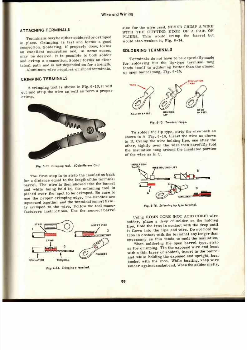
7/26/2019 Auto Service and Repair - Martin W. Stockel
http://slidepdf.com/reader/full/auto-service-and-repair-martin-w-stockel 99/224
.
Wire
ond
Wir ing
li
OPEN
BARREL
^-'Y)
6l
LOSED
BARREL
ATTACHING
ERMINALS
Terminals
maybe
either
soldered
or
crimped
in
place.
Crimping
is
fast and
forms
a
good
connection.
Soldering,
if
properly
done,
forms
an
excellent
connection
and,
in some
cases'
may
be
desired.
It
is
possible
to
both
solder
and
crimp
a connection.
Solder
forms an elec-
trical
path
and
is not
depended
on
for strength'
Aluminum
wire
requires
crimpedterminals'
CRIMPING
TERMINALS
A crimping
tool
is
shown
in
Fig'
6-13'
it
wil l
eut
and
strip
the
wire
anwell
as
form
a
proper
crimp.
size
for
the
wire
used.
NEVER
CRIMP
A WIRE
WITH
THE
CUTTING
EDGE
OF
A
PAIR
OF
PLIERS.
This
would
crimp
the
barrel
but
would
also
weaken
it ,
Fig.
6-14.
SOLDERING
TERMINALS
Terminals do not have to be especiallymade
for
soldering
but
the
lip-type
terminal
tang
lends
itself
to
soldering
better
than
the
closed
or
open
barrel
tang,
Fig.
6-15r
INSULAf
ON
TANG
Fig'
6'13'
Crimping
tool'
(Cole-Hersee
Co'l
The first step is to strip the insulation
back
for a
distance
equal
to
the
lengthof
the
terminal
barrel.
The
wire
is
then
shoved
inio
the
barrel
and
while
being
held
in,
the
crimping
tool
is
placed over
the
spot
to
be crimped'
Be
sure
to
use
the
proper crimping
edge.
The
handles
are
qrru d
together
and
the
terminalbarrel
f irm-
ly
crimped
to
the
wire.
Follow
the
tool
manu-
fácturers
instructions.
Use
the
correct
barrel
CRIMP
I
@
tt
|NSULAT|ON TER$INAL
Fig'
6'15'
Terminol
tangs'
To
solder
the
lip
type,
strip
the
wireback
as
shown
in
A,
Fig.
6-16.
Insert
the
wire
as
shown
in
B. Crimp
the
wire
hotding
lips,
one
after
the
other,
tightly
over
the
wire
then
carefully
fold
the
insulation
tang
around
the
insulated
portion
of
the
wire
as
in
C.
INSULATION
TANGS
WIREHoLDING
LIPS
M:d
Eio
'l;*
^t-fu
Fig.6-16,
Soldering
ip
rype
terminal '
Using
ROSIN
CORE
(NOT
ACID
CORE)
wire
solder,
pt a
drop
of
solder
on
the
holding
tips.
Iiotá
the
iron
in contact
with
the
drop
until
it
flows
into
the
lips
and
wire'
Do not
hold the
iron in contact with the terminal anylongerthan
necessary
as
this
tends
to
melt
the
insulation'
When
soldering
the
open
barrel
t¡rpe'
strip
as
for crimping.
Tin the
exposed
wire
end
(coat
with a
thin
layer
of
solder),
insert
in
the
barrel
and
while
holding
the
exposed
end
upright'
heat
socket
with
the
iron.
While
heating,
keep
wire
solder
against
socket
end.
Whenthe
solder
melts'
INSERT
TTIRE
Fig.
6-14.
CrinPing
o
terminol '
99

7/26/2019 Auto Service and Repair - Martin W. Stockel
http://slidepdf.com/reader/full/auto-service-and-repair-martin-w-stockel 100/224
Auto
Service
ondRepoir
f low it
into
the
barrel.
Make
certain
a sufficient
amount
enters.
Hold
the
iron
in
place
for
a few
seconds
longer
to
allow
the
solder
to
bond
to
both
barrel
and wire.
Barrel
may
also be
cri.mped
if
so desired.
Crimp
before
soldering
Se e
Fig.6-17.
barrel
until
about
one-quarter
futl.
While
retain_
ing
the
heat
with
the
torch,
force
the
tinned
cable
down
into
the
socket.
When
it
slips
in
the
fut l
depth,
solder
will
flow
up
and
over
the
tip of
the
barrel.
Hold
the
heat,
moving
the
flame
around
the
terminal
outside,
fon
a
fewsecondslongerro
allow
the
heavy
cable_,íó
heat
up
andbond
firmly
to the barrel. Remové heat andholdcable steady
until
solder
sets.
CooI
under
a cold
tap.
.Dry
terminal
and
cable
insulation
and
then
apply
plast ic
tape
as
shown
in Fíg.
6-1g.
For
open
barrel
termi.nals,
t in
both
cable
and inside
of
sTRtP Tt N
TINNED
\
_l
¡E3
\
r
_
t
É*E
^:
isii:F"l
Ün(-
U"
SOLDERING
IRON
Fig.6-17.
Soldering
orrel
ype
erminol
ong,
The
closed
barrel
type
should
be heated
an da
small
amount
of solder
flowed
into
the hole.
While
keeping
the
barrel
hot,
press
the
tinned
wire
into
the
hole. HoId
the iron
in
place
fo r
several
seeonds
to insure
bonding.
For
more
complete
instructions
on
the
use
of the
soldering
iron,
see the
chapter
on
solder-
ing,
brazing
and
welding.
When
an insulator
boot
is
to
cover
th e
terminal
tang
or
when
attaching
slide
type
terminals
that
wil l
be
snapped
back into
a
housing,
always
slide
the
boot,
housing,
erc.,
on
the wire
before
soldering.
SOLDERINGBATTERY TERMINALS
The
common pract ice
is
toreplace
the
entire
battery
cable when
the
terminals
are
no
longer
f it
for
use. However,
if
it
becomes
necessary
to
install
a new
terminal,
use
the following
procedure.
Cut
the
cable
back
far
enough
to
remove
th e
corroded
section.
Peel
the
insulat ion
(ground
cables
often
have
none)
back
equal
to the
depth
of
the terminal
barrel.
place
the
terminal
in
a
vise,
open
barrel
end
up.
Using
an
acetylene
torch
(low
heat,
flame
rich in acetylene) heat the stripped cable end.
Using
rosin
core wire
solder,
f lowsolderfreely
into
the
wire
unti l
all
strands
have
been
tinned.
It
may
help
to rub
onalit t le
rosin
tJrye
soldering
paste
to
assist
with
t inning.
Place
a
dab
of
solderingpaste
inthe
terminal
barrel.
Hedt
with
the
torch
(keep
flame
on
out-
side
of terminal).
When
hot,
f low
solder
intothe
Fig.6-18,
Soldering
o battery
terminol.
I-Cut
oÍl
corroded
sec_
tion.
2-Strip.
3-Tin.
4-Tin
borre
and
odd
solder.
S_lnserr
co6le.
6-Tape.
res@N
Wwffi
Fig..
6-19.
Spork
lug
wire
ferminols
ond boots.
I, 2,7-dist¡ ibutq
end te¡minals.
3,
4, 5,
6,8,
l l-spork plug
end
terninols.
9-Right
ongle
distr ibutor
end
6oot.
l I-F lexible plug
end6oor.
l2_sropies
{or
use
with ¡esistonce
type
wire.
I3-Replocemen
plug
wire with
.
6oofs
6onded
to
wi¡e.
t00
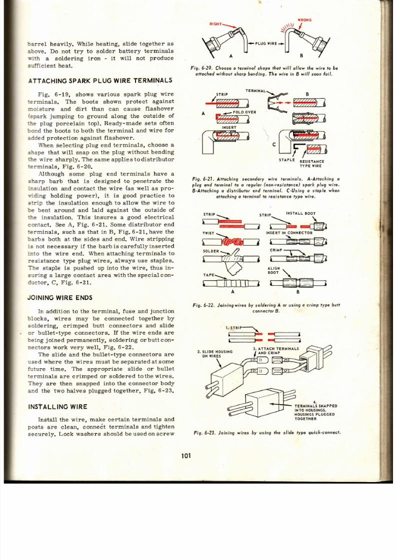
7/26/2019 Auto Service and Repair - Martin W. Stockel
http://slidepdf.com/reader/full/auto-service-and-repair-martin-w-stockel 101/224
SX
barrel
heavily.
While heating, slide
together
as
above. Do
not try
to solder
battery terminals
mith
a soldering
iron
-
it
will not
produce
s':¡fficient heat.
ATTACH¡NG
PARK
LUG
WIRE
TERMINALS
Fig. 6-19, shows various spark plug wire
:erminals. The
boots
shown
protect against
noisture
and dirt
than can
cause
flashover
fspark
jumping
to
ground
along
the outside
of
:he plug porcelain
top).
Ready-made
sets
often
bond
the boots
to both the
terminal and
wire for
added
proteetion
against
flashover.
When
Selecting
plug
end terminals,
choose
a
shape that
will
snap
on the
plug
without bending
:he wire
sharply.
The
same applies
to distributor
terminals, Fig. 6-20.
Although
some
plug
end terminals
have a
sharp barb that is designed to
penetrate
th e
r.nsulation
and contact
the
wire
(as
well
as
pro-
viding holding
power),
it is
good practice
to
strip the insulation enough
to
allow
the
wire to
be
bent
around
and
laid
against
the outside of
'üe
insulation,
This insures a
good
electrical
contact. See
A,
Fig.
6-21. Some distributor
en d
terminals,
such as that
in B,
Fig.
6-21,
have the
barbs
both at the
sides and end. Wire
stripping
:s not
necessary
i f the barbiscarefu lly inserted
i¡rto the wire
end.
When attaching
terminals
to
resistance type
plug
wires,
always
use staples.
The
staple is
pushed
up
into
the
wire,
thus
in -
suring a large
contact
area
withthe specialcon-
ductor, C,
Fig.
6 '21.
JOINING
IRE
ENDS
In
addit ion
to the terminal,
fuse and
junction
blocks, wires
may be connected
together
by
soldering,
crimped
butt
connectors
and
slide
or bullet-tJ¡pe connectors.
If
the
wire
ends
ar e
being
joined
permanently,
soldering
orbutt con-
nectors work
very
weIl,
Fig.
6-22.
The
slide and
the bullet-type connectors
are
used where the
wires must be separated at some
future time.
The
appropriate slide
or
bullet
terminals
are crimped
or soldered
tothewires.
They are then snapped into the connector body
and the
two halves
plugged
together,
Fig. 6-23.
INSfALLING
WIRE
Install the wire, make certain
terminals
an d
posts
are clean, conneót
terminals and
tighten
securely.
Lock washers
should
be
used on screw
PLUGWIRE
Fig.
6-20.
Cfioose
o le¡minal
shope
hot
wi l l a l low the wjre
to
6e
al tached
without
sharp
bending,
The
wire in
B
wi l l
soon
oi l ,
TE
RMINAL.
/5TR|P
-\
áe@ B
@r-
Kr-- t - . ' ,
off i , *
*w
INSERT
STAPLE
nestsl ¡xce
TYPEWIRE
Fig.
6-21.
Attaching
secondory
wire terminols.
A-Attaching
o
plug
end lerminol to o
regulor.(non-resisfonce) pork
plug
wire.
B-Attoching o distr ibutor end terminol , C-Using o sfop/e wfien
ottoching
o terminol to resistonce
type wire.
srRtP
\-
STR¡P_
INSTALL
OO-T
-\..
\ \
¡
F--
\-
:-
--s----7r------á+]
TWIST
-
INSERT
N CONNECTOR
>-^
\
M---
5--ErE¡
ALIGN
\
BOOT
\
;..---
r r i l l l t tT-_]
5--EJEf-- l
A
Fig. 6- 22, J oining
wires
B
by solderingA
or using
o crimp type butl
connecfor .
'J" ' ] :
f_---__--F
I:
3, ATTACH TERMINALS
AND CRIMP
4,
TERMINALS
NAPPED
INTO
HOtJSINGS.
HOUSINGS LUGGED
TOGETHE
type
guick-connecf.
101
Fig.6-23. Joíning
wires
by using the sl ide

7/26/2019 Auto Service and Repair - Martin W. Stockel
http://slidepdf.com/reader/full/auto-service-and-repair-martin-w-stockel 102/224
w
ttrz
@
re^/tg=
Auto
Serviceond
RePoir
ffi
cy's
s_
e*ffi-
É*r
ñ@E
I
I
Fig.
6-24. Yliring
instollation
hints. A-Connecfions
musf 6e
CLEAN
and BRIGHT.
B-Use
grommets
o
Prolect
wire
possing rhrough-thick
metol. C-Tope
common
wires fogelfier. D-Avoid
moving
porls
when
locoting wíres' E-Sup-
'porr
with suitolle
clomps.
F-AIIow
some
slcck
when wire
runs to o unit
thot moves. G-Connecfors
musfáepusfted
together
tightly. H-llse
6oots on
terminol
tongs
and select terminols
Éeovy enough
(or
the
iob,
l'Tighten
termi-
nil ¡n
o
fo ;iion
AWAy FROM
metol
-
use
6oots olso. J-Hondle
resislonce
plug
wires
by
grasping tfieboots.
lLi
. rl
$
I
.,)l
: ' l '
1l
and
post
connections.
Stip
insulatorboots,
where
used,
over
exposed
terminal
tang.
If
of
the
slide
or
bullet
t¡pes,
shove
together
tightly
andeheck
to see
that the connection
is secure.
Keep all
wiring away
from
the exhaust
sys-
tem,
bily
areas
and
moving
parts.
Secure
in
place with mounting clips.or clamps. Fasten in
enough
spots
to
prevent
excessive
vibration
and
chafing.
Where the
wire
must
pass
through
a
hole
in
sheet
metal,
install
a
rubber
grommet
(see
Fig. 6-241
When a
wire
must
pass
from
the
fender
well or
splash
shield
to
the engine,
leave
enough
slack
to allow
the engine
to rock
on
the
mounts
without
pulling the
wire
tight.
Wtren
nstall ing
spark
plugleads, avoidsharp
bends.
If the
wires
pass
through
a
metalconduit
(tube),
the conduit
should
be securely
grounded.
Install or
remove
the
plug wires by
grasping
the
insulation
boots
and
not
the
wire
proper.
Make sure the terminals snap tightly on the
plugs
and
that
the distributor
ends
are
all the
way
in the
housing
towers.
Follow the
manu-
facturers
instructions
in arranging
the
plug
wires.
If two
leads
are
together
going to cylin-
ders
that
fire consecutively
(one
afterthe
other)
there
is
a
danger
ofcrossfiring -
especiallyas
the
wires
age.
If a number
of
primary
wires travel
in
a
common
path,
pull
them
through
loom
(woven
fiber conduit)
or
tape
them
together,
Fig. 6-24.
FUSEWHEN
NEEDED
When adding
accessory
units such
as
spot-
l ights,
heaters,
etc.,
and
no
provision was
made
for
them
in the original
wiring, be certain
to
place
a
fuse
in the circuit.
Fuse
as
closely
as
possible to the electrical
source.
This
will
reduce.
the
possibil ity of
a short
between
the
fuse
and souree.
A
small
fuse block
may be
used or
the
popular
in-line
lfuse
canbe
installed.
Be
sure
to
inform the owier
as to the
location
of
the new
fuse,
Fig. 6-25.
NEVER TAP INTO
(CONNECT)
THE HEAD-
LIGHT
CIRCUIT
TO
POWER
AN
ACCESSORY.
THIS
COULD
OVERLOAD
THE HEADLIGHT
CIRCIIIT BREAKER AND CAUSE TROUBLE.
If it is desired
to
have radios,
heaters, etc.,
in -
opet'ative
when the
ignition key
is in the
OFF
position,
the unit
hot
wire must
be
connected
to
the
key switch.
PRINTED
IRCUITS
A number of cars
use a
printed
circuit
as
part
of the
instrument cluster
wiring system.
The
printed
circuit
uses a
nonconducting
panel
upon
which certain
units are
attached.
Instead
of connecting
the units
with
wires, they are
connected with thin conductor str ips printed
(cemented)
on
the
panel.
Such a technique
per-
mits
a
great
deal of circuitry
in a
very
small
space.
CHECKING
IRING
Many
problems
throughout
the car
can
be
traced
to
faulty
wiring.
Loose
or corroded
terminals,
frayed
and
bare spots,
oil soaked,
broken
wires,
and
cracked
andporous
insulation
are
the most
frequent causes.
When troubleshooting a proJrlem, check the
wires,
fuses and connections
carefully.
Re -
member
that
wires
can
separate
with no
break
in the
insulation
(especially
resistance
type
secondary
wire). A terminal
may be tight
and
still
be corroded.
A
fuse link
may burn
out at
one
end
instead of
in
the
center
where it
will
be
visible.
il
t:
i
;
tü2

7/26/2019 Auto Service and Repair - Martin W. Stockel
http://slidepdf.com/reader/full/auto-service-and-repair-martin-w-stockel 103/224
CHECKING
OR
CONTINUITY
A
small
test
light
(battery
operated) may be
::sed
to test
wires for
internal breaks.
The
test
point
prods
can
be
pushed
through the insulation
:i
desired
(not
on
plug
wires). Hold
one
prod
e-gainst
one end of the
wire
and
place
the other
INSULATOR UBE
IN5ULATING
WASHER
Ftg.6-25.
Typical
in- l ine Íuse.
Fuse
os close to f f ie
source
os
prociicol.
; :od
against
the other end. Ifthe
test lamp burns,
:he
wire
is
continuous.
This
simple test l ight
:s
also handy for
checking fuses,
shorted
field
x:ndings
and
for
tracing
wires
where
there are
: :c
color
codes.
F ig.6-26,
i l lustrates
several
:
- recks.
3
E.
6-26.
Some
wir ing
checks using o
simple
test l ight.
A-Prods
¡n
ends
oÍ wi¡e. Lomp l ights
indicating wire ís
continuous, B-
e cd
held
on the
end ol one wire ond
the other
prod
¡ouched ¡o
,:r ious
wi¡e ends.
W[en lomp ights
proper
wirc
end s idenri l ied.
C-C/recking
o fuse. P¡dds
in
ploce,
lomp does not
light.
This
in -
t cdtes
o loulty
luse and in
this cose ffie luse will
be
burnl out
r tlre
end insteod
oÍ the usuol norrow
centeÍ seclion.
D-One
prod
¡ucÁed
to
o wire end and
the othe¡
prod
to
ground.
Il lamp lights
wire is
shorted out.
OTHER
HECKS
Wires
and connections must
occasionally
be
checked
for
resistance,
voltage drop,
short
or
near-short
circuits.
These
checks
are
made
with
precision
instruments
- ohmmeter,
volt-
meter ,
etc. ,
and
wi l lbe
discussedinthe
chapters
to which
these
tests
pertain.
SUMMARY
Primary
wire
(copper
stranding, relat ively
thin insulat ion)
is
used for
circuits handling
battery
voltage.
Secondary wire
(stainless
steel,
carbon
impregnated
thread
and
elastomer
stranding wi. th
very heavy insulat ion)
is used on
the
ignit ion
hightension
circuit .
Plast ic
is widely
used
for
insulat ion.
AII
automotive wire
uses a stranded
(not
solid) wire
conductor.
The
AWG
(American
Wire
Gauge) is deter-
mined
by the
cross sect ional
area in
circular
mils. The
larger
the AWG number,
the smaller
the size. A microrheter
or
wire
gauge
can
be
used to determine wire
size.
Spade, lug, f lag,
ro11,
slide, r ing and bullet
terminal types
are used.
Terminal
blocks allow one feeder wire
to
service
a
number
of other
wires. These
ca n
be of the screw,
bullet or slide tJpe.
Junction
blocks
provide
a central
connecting
point
for
a number of wires.
Fuse
llocks
give protect ion
against
circuit
overloads.
A
wiring harness
contains a number
ofwires
either taped together
or
pulled
through
loom.
This
keeps
common
wires
neatly
arranged and
facil i tate
s
installat ion.
Automotive
electr ical
systems are color
coded.
Use
an accurate
wiring
diagram for
troubleshooting
or replacing
wires.
Line
voltage,
wire
length
and electr ical load
must
be taken
into consi.derat ion when
choosing
wire gauge.
A wire
gauge
chart
wil l
assist
in
making the right
select ion.
Remember
that
unders ize wires increase
resistance, reduce
unit eff iciency and can overheat and burn. On
two-wire
circuits
(one
wire for
ground)
count
the length
of
both wires. A 6v.
system requires
heavier
gauge
wire
than the 12v.
system.
Be
certain that terminals
are
of the
correct
style and size.
They
maybe
soldered
or
crimped
to
the wire. Battery
replacement terminals
should be soldered.
When
crimping, use a suit-
Wire
qnd
Wir ing
CONTACT
TERMINAL
103

7/26/2019 Auto Service and Repair - Martin W. Stockel
http://slidepdf.com/reader/full/auto-service-and-repair-martin-w-stockel 104/224
AutoService
ond
Repoir
able crimping
tool.
If
soldering, use
rosin
core
wire
solder.
Always slide insulation boots,
housings, etc., on the'.wire before
attaching
terminal.
'Use
staples
when
installing terminals onre-
sistanee t¡rpe secondaryleads.
Handle
secondary
resistance
wire
carefully.
.Wire ends may be joined by soldering, using
butt
connectors
or by
attaching
bullet or
slide
connectors.
When installing wíres,
keep away
from
heat,
oily areas and moving
parts. Terminals
must
be clean
and
tight. Use
clips
to
prevent
chafing
and excessive vibration.
When
adding accessories,
fuse
the
circuit
as
close
to
the source as
possible.
Do
not tap
into
the headlight
circuit
for
an accessory.
Clean, tight
connections
with
propet
size
wire
and
good
insulation,
are imperative.
When
troubleshooting,
always check
connections
and
insulation. Replace cracked, spongy or frayed
wires.
Many
wiring
checks
can be
made wíth
a
simple test
light.
Printed
circuits
find
some application onthe
auto.
SUGGESTED
CTIVITIES
1.
Using
the
primary
wire
size selection chart
in
this
ehapter, determine
the
correct size
wire for
the following:
A. Load
-
100 candela
Wire length - 11 feet
Voltage
-
12
Wire
gauge
should
be_.
Loád
-
50
amperes
Wire length
-
2O feet
Voltage
-
12
Wire
gauge
should be_.
Load
-
70 watts
Wire
length
-
15
feet
Voltage
-
6
Wire
gauge
should be_.
Attach
several terminals bycrimping. Solder
several.
On a damp, dark night, start the engine in a
car
(especially
one several
years
oldthathas
been
parked
outside). Without turning on the
lights,
raise the hoodandseeifyoucan detect
the
corona
effect around the
plug
wires.
DO
.NOT
RUN THE
CAR
IN
A CLOSEDGARAGEJ
Inspect
the
wiring
on
a late
model
car.
What
kinds of terminals
are
used? Studythe
wiring
harness
and
see
how many
kinds
ofwireclips
and clamps you
can
find.
5. Study
the wiring
diagram
of a
car electrical
qystem.
Trace
several
circuits
starting at
the unit
and
going
back to
the source. Note
the
color coding
and use
of symbols.
TOOLS
ARE
IMPORTANT
Remember
-
to do
good
work,
a
mechanic
needs
a
good
assortment
of
tools. To
learn, a
student needs
a
good
assortment
of
words.
Words
are
very
important
t'toolstt
for learning.
When
YOU
come
across
a new word LOOK
UP THE
MEANING
and
add
it
to
your
TOOL
CHEST.
OUIZ
-
ChoPter
1.
Primary
wire makes
excellent
spark
plug
leads. True or False?
2.
The
most
commonlyused
insulation material
is- .
3.
Resistance
tJ@e spark
plug
wires
are used
to
provide
a
hotter
spark.
True
or
FaLse ?
4.
Name
three materials,
used
for
secondary
wire
stranding.
5.
Stranding for
primary
wire is
made of
6.
Resistor
spark
plug
cables are
easily
damaged by
sharp bends
and
jerking.
True
or
False
?
7.
All
primary
automotive wire
uses a stranded
conduetor. True or False.
8.
The
is
the standard
for wire
size.
9.
The
larger
the wire number,
the larger the
wire.
True
or
False
?
10. Cross sectional
area in square mils
de -
termines the wire
size.
True
or
False ?
11.
Name five
common
primary
terminaltypes.
12.
Replacement
battery
cable terminals should
One feeder
wire
can service
several others
through the
use of a_block.
A
number
of
wires
can be
connected to-
gether. in a common location by using a
_b1ock.
15.
The_protects
a
circuit
from
an
overload.
A number
of
common
wires,
tapedtogether,
with leads
leaving at
various spots.i, s re-
ferred to
as a
wiring_.
Automotive
wiring
is_ coded.
1,
ü
B.
C.
be
13.
14.
2.
3.
16.
4.
tu
t7.

7/26/2019 Auto Service and Repair - Martin W. Stockel
http://slidepdf.com/reader/full/auto-service-and-repair-martin-w-stockel 105/224
Wire
qnd
Wir ing
I
I
t
21.
22 .
24.
25.
26.
27.
28 .
29.
18.
What is a
wiring
diagram?
19.
The three
major considerations
inselecting
the correct
wire
gauge for
a
specific circuit
are
,
wire
-and
30.
31.
lectrical
-.
20.
An
undersize
wire
will increase
and
will_,
23.
In computing wire length for a twowire cir-
cuit,
both
wire lengths
should
be counted.
True
or
False ?
No. 16
wire is smaller
than
No.
18
wire.
True
or
False?
-is
the
international
term
for
candlepower.
12 volt
wiring
is
of
aheaviergaugethan
that
for 6
volt.
True
or
False ?
As long as a
terminal
fits the stud
or
post,
i t is
O.K. to use.
True
or
Fa1se?
terminals
to the
wire
is more
widely used
than
.
Use-when attaching terminals to
resistance
t¡pe secondary
wire.
Copper
or stainless
steel
secondary
wire
should
have a smalL
portion
of
theinsulation
stripped
and
the wire bent
up andaroundthe
outside
of the
insulation.
True
or
False ?
If,
when
joining
wire ends,
it
is desirable
to
be able to disconnect them at a
future
date,
a_type connector
would
be a
good
choice.
As
long as a
connection
is
t ight,
it wil l be
a
good
conductor.
True or
False?
Grommets are used to
proteet
wire
passing
through thin
sheet
metal.
True
or
False
?
32. When plug leads pass through a metal con-
duit, the
conduit
should be_.
33. Wires
should
be held by in order to
prevent
ehafing
and vibration.
34. Spark
plug
wires can-if
wires
ar e
too
close
together
whentheyserve
cylinders
that fire
consecutively.
35. As
long as
the insulation is alright, a
wire
can be considered
O.K. True
or
False?
36.
A
frayed
wire
can cause
a_circuit.
37.
A
corroded connection
will
increase_
to electrical flow.
38.
The
electrical symbols
in the
left
hand
column are all numbered. Write down these
numbers, one beneath the other.
The right
hand
column
lists
the
items these symbols
stand
for.
Each
item has a letter.
Matchthe
items to the
symbols
by
placing
the letter of
the item
you
have
chosen
beside thenumber
of the matching symbol.
A. Resistor.
B.
Ci¡cuit
Breofte¡.
l .
Switcñ.
J.
Rfieostof.
K. Tronsistor.
L.
Bottery.
M. Negofive.
N.
Condenser,
O.
Ground.
,
cf\
,.
rlrlrlrlrlrp
2.
^,J
+-o-
-l>
-a,AAr
<A
Ar
L
4.
7.
+
+
f-
-J
'
@
t0 .
t I .
t2 .
t3.
14.
t5.
'++
lfires
Crossing
-
Not Connected,
Fuse.
E. Diode.
F.
lfires
Crossing
-
Connecfed,
Posilive.
Te¡minol.
Fig.6-27.
A-Fuse
btocx
incorporoting
o number oÍ
miniolu¡ized
fuses.
B- Good
miniolu¡ized fuse.
Nofe
tñot
elemenf
is sound.
Cu¡renl
flows
l¡om one
blode, lhrough element
ond
out tfie otfier 6lode.
C-Fuse
is
Bod.
Elemenf
is Aurned n holÍ,
thus opening
circvit.
(Pontioc-Buick)
c.
D.
G.
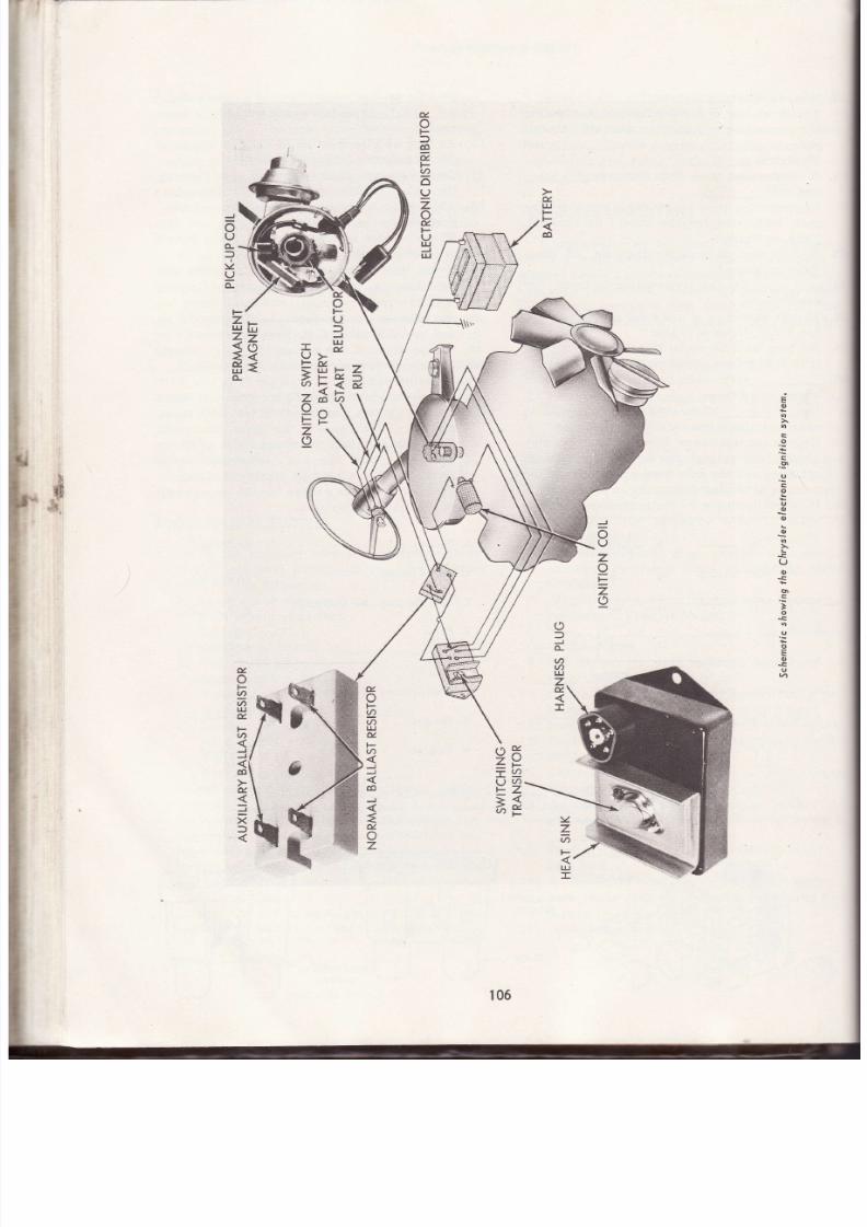
7/26/2019 Auto Service and Repair - Martin W. Stockel
http://slidepdf.com/reader/full/auto-service-and-repair-martin-w-stockel 106/224
u
tu
l*
F
co
F
6
F
I
¿f
L]
z
ü
t-
at
J
UJ
J
o
U
-
I
v
I
z
)
u
L)
J
t¿r
u
F
x,
F
u
UJ
F
F
eo
o
t-
T
U
F
=
tt
z
a
z
CI
l*
l¿¡
z
=
F
z
t¿J
z
=
u,
uJ
E
o
U
o
U
o
o
o
\
U
o
o
]
I
o
u
J
6
z
a\
tr
z
;
b
#
.*.
/\
o¿
zY
r.u
v2
=*
a;.
u,
o
F
tÍ)
6
¡¿l
d
F
./)
J
J
co
J
=u
z
o
)
J
v)
a
t¡J
z
d.
:¿
z
6
F-
ul
I
o
F
v,
v>
UJ
u,
F
*t>
J
o¿
I
j
X
106
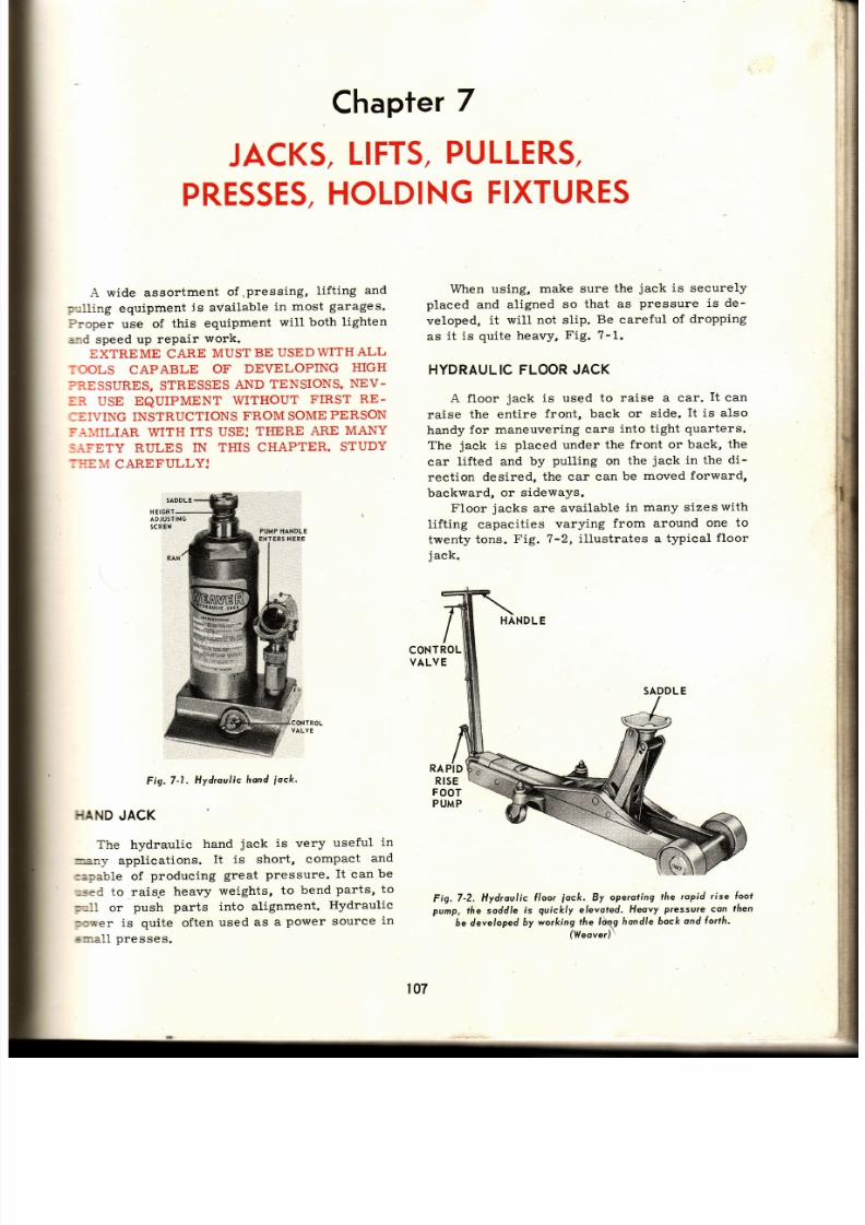
7/26/2019 Auto Service and Repair - Martin W. Stockel
http://slidepdf.com/reader/full/auto-service-and-repair-martin-w-stockel 107/224
Chapfer
7
JACKS,
IFTs,
ULLERS,
PRESSES,OLDING IXTURES
A wide assortment
of
,pressing,
Iifting
an d
p.;lling
equipment
is available
in
most
garages.
Proper
use
of
this equipment
will both
lighten
and speed up
repair
work.
EXTREME CARE
MUSTBE
USEDWITHALL
TOOLS
CAPABLE
OF DEVELOPING
HIGH
?R,ESSURES,
STRESSES
AND
TENSIONS.
NEV-
=R USE EQUIPMENT
WITHOUT
FIRST
RE -
:EIVING INSTRUCTIONS FROM SOME PERSON
:.I,IÍILIAR
WITH
ITS USE:
THERE
ARE
MANY
S.iFETY
RULES
IN
THIS CHAPTER.
STUDY
:ITEM
CAREFULLYJ
Fig.7 1.
Hydroulic
hond
iock
}IAND
ACK
The hydraulic
hand
jack
is
very
useful
in
rmany
applications.
It is short,
compact
and
eapable of
producing
great
pressure.
It
can be
used to raisg
heavy
weights,
to bend
parts,
to
p rll
or
push
parts into alignment.
Hydraulic
poffer
is quite often
used
as a
power
source
in
sme1l
presses.
When using,
make sure
the
jack
is
securely
placed and aligned
so
that as
pressure is de-
veloped,
it
will not slip.
Be
careful
of dropping
as
it is
quite
heavy,
Fig.
7-1.
HYDRAULIC LOOR
ACK
A floor
jack
is usqd
to
raise a car.
It
can
raise the entire front, back or side. It is also
handy
for maneuvering
cars
into tight
quarters.
The
jack
is
placed
under
the
front or back,
the
car
lifted and
by
pulling
on
the
jack
in the
di -
rection
desired,
the
car
can
be
moved
forward,
backward,
or
sideways.
Floor
jacks
are available
in many sizes
with
lifting capacities
varying
from
around
one to
twenty
tons.
Fig.
7-2, i l lustrates
a typical
floor
jack.
HANDLE
Fig.7-2.
Hydroulic
( loor
iock.
By
operoting
the ropid
rise
loot
pump,
the soddle
ís
quickly
elevoted.
Heavy
Pressu¡e
con
then
be developed
by wo*ing
rhe
t\s hondle
bock
ond
lorth
(Weove¡)
PUMP TANDLE
CONTROL
VALVE
RAPID
RISE
FOOT
PUMP
SADDLE
107

7/26/2019 Auto Service and Repair - Martin W. Stockel
http://slidepdf.com/reader/full/auto-service-and-repair-martin-w-stockel 108/224
Fig.7-3.
poísing
co¡
with
lloor
iock,
Moke
cerfoin
soddle
is
ProPerlY
Positioned.
(Honda)
PROPER
PLACEMENT
IS
IMPORTANT
When
positioning
the
jack
saddle
for
lifting,
make certain
it
is securely
engaged.
Select
a
spot that will be strong enough to support the
Fig.7'4'
Typicol
odiustoble
ock
slond'
load.
Never
try
raising
the
car
by
jacking
on
the
engine
pan, cluteh
housing,
transmission'
tie rods, gas tank, etc.
Proper
placement
requires
care'
GET
DOWN
AND
TAKE
A GOOD
LOOK,
WITH
AMPLE
LIGHT,
BEFORE
RAISING.
If the
car
is
part
way
up,
andthe
jack
saddle
slips,
serious
damage
can
oecur.
On some
cars,
jacking one
side
of
one
end
or
near
the center
of
the
frame
on
one
side,
can
cause
damage.
Car
manufacturers
il .ustrate
correct
lifting
points
intheir
manuals'
You must
follow
the
manufacturerrs
specifi-
cations
carefully.
Fig.
7-3 shows
a car
being
raised
by
plaeing the
saddle
under
the center
of
the
differential
housing.
NEVER
WORK
UNDER
A VEHICLE
SUP-
PORTED
ONLY
BY
A
FLOOR
JACK;
Once the
car is raised to the desired height,
place
jack
stands
in
the
desired
location,
and
lower
the
weight
onto
the
stands.
STANDS
MUST
BE
PROPERLY
AND SECURELY
PLACED.
The
jack
may
then
be
removed
if
desired,
or
if
not
needed
in some
other
area,
it may
be
left
in
position
with
a very
light
liftingpressure
exerted
to
keeP
it
Positioned.
JACK
STANDS
Jack
stands
are
made
in
numerous
heights
and
are
usually
adjustable.
The
stand
in
Fig.
?-4 is typical. Note
the ratchet
adjustment.
When
insert i.ng
jack
stands,
place
them
in
contact
with
some
unit capable
of
supporting
the
load. Do
not
place them
in contact
with
tapered
edges
that
may
cause
them
to s1ip.
Make
sure
they
have
a
secure
bite. Fig'
7- 5
shows
a
pair
of
jack
stands
(often
called
safety
stands)
in
place under
the
rear
axle
housing. Note
that
the stand
tops
(saddles)
are
properlY
Posit ioned.
Fig.7-5.
Properly
ploced
iock
sfonds
províde sofe
supporf'
(Honda)
ENDLIFTS
The end
lift can
be
air
(pneumatic)
or
hy-
draulically
operated.
Two basic
designs
are
used,
one
of
which
will
reach
under
the
car
far
enough
to contact
the
rear
axle
housing,
and
the
other
designed
to engage
the
bumper
only'
An
air-operated
long-reach
end
lift
is
pic-
tured
in
Fig. ?-6.
Notice
the
height
to
which
th e
ATCHET
EETH
TCHET
108

7/26/2019 Auto Service and Repair - Martin W. Stockel
http://slidepdf.com/reader/full/auto-service-and-repair-martin-w-stockel 109/224
Fig.7-6. Long
reochend l i ( t .
(Hein-Ylerner)
::r '
may be raised.
The
jack
stands are
being
car
issitioned
so that
when
the rear
of the
:-,¡;ered,
the front wil l
c lear
the
floor.
The
bumper l i ft shown
in
Fig. 7-7 is also
::r -operated.
Note
the twin saddle
engagement,
Fig.
7-7.
Roising
cor wi th o bumperend
l íf t .
-:re
distance
between
saddles
mav
be varied to
-:gage
the bumper
where
desired.
Remember
::at
bumpers,
especially near the
outer
ends,
=ay
not
be
particularly
strong. If the bumper
: a¡
be
used,
prace
the
saddles at the
main
bumper
: frame attachment points.
End
l i f ts
are
generally provided
with
strong
:.fety
locks
so
the mechanic may safely
work
eneath the car
without
iack
stands.
MAKE
-= trgdLrt
L l lg
( ;dt
wrLttvuL
Jdu^
DldrruD.
: ' '-T.E THE
SAFETY
LOCK IS FULLY
ENGAGED,
'.\D
THAT
THE
LIFT CONTACT
POINTS
AR E
SOLID. If
there
is the slightest
doubt,
use
iack
-.tands
or
additional
protection.
FAST,
LOW
LEVEL AIR LIFT
A handy, quick-acting air l i ft
is
i l lustrated
in
Fig.
7-8.
The
car
is driven over the l i ft unti l
the rear
wheel is
centered
in the frame.
A
con-
trol box
actuates
the rubber air bellow
which in
turn
causes
the saddle to
lift the
car.
This
jack
is useful for washing rear wheels partial ly
covered
by the body.
Fig.7-8, Low level , wash rack / i f f . Nofe rubbe¡bel lows.
SINGLE
POSTFRAME
LIFT
A
single
post
frame lift leaves bothfrontand
rear of the
car
completely exposed.
It
does how-
ever,
create
some obstruction
in
the
central
por t ion. Fig. 7-9,
shows a
car
in
the raised
position
on
a
single
post
frame l i f t .
Note
the
lift
contact
points
on
the frame.
REMEMBER:
PROPER
CONTACT
POINTS FOR DIFFERENT
CARS VARY.
FOLLOW MANUFACTURERSI
IN-
STRUCTIONS.
Fig.7-9.
Single
post
l ¡one l i l t .
Note
coreful
plocing
o(
l i l ¡
sod-
d/es or brockets.
DOUBLE OST RAME ¡FT
The
double
post
frame lift eliminates
the
single central
post
thus leaving
the center
portion
of
the
car
more accessible.
As
with
the
single
post
l i ft, the car
must be
carefully
centered.
In
Fig. ?-10,
the
mechanic hascenteredthecarand
is
adjusting the swivel
l i ft arms.
109

7/26/2019 Auto Service and Repair - Martin W. Stockel
http://slidepdf.com/reader/full/auto-service-and-repair-martin-w-stockel 110/224
st
'c
Fig.
7-10.
Adiust ing
swive/
qrms
on double
Post
rome
il l
Fig.
7-l l .
Double
post
(rame
li l t"
Co¡
mus b e care{ully
centered.
CONTACTS
EA R
Auto
Servicednd
Repdir
An auto
is
shown
in the ra ised
posit ion
in
Fig. 7-11.
The
equal izer
racks insure that both
colurnns
wil l
ra ise and
lower together.
DOUBLE
POST
SUSPENSIONIFT
The
double
post
l i f t
p ictured
in
Fig.
7-12,
contacts
the
front
suspension arms, and e ither
the rear axle
housing,
or. rear
wheels.
The
front
l i f t
co lumn
can
be moved
forward
or backward
to adjust
for
var ious
wheelbase
lengths.
This
type
of
l i f t
presents
a
minimal
amount of under-
car
obstruct ion.
On
some
models,
a
single
column
can be raised
thus
act ins
as
an
end l i f t
when
so desired.
DRIVE-ON
LIFT
The
drive-on
1if t ,
Fig. 7-13, offers
place-
ment
speed
but does
present
a
re lat ive ly
large
obstruct ion
area.
CHOICEOF
LIFTS
^
^
--
^"
L
^. '^
-
^f
i nFd cech I i f t of fe
rs s ome
5
.y
uu
I ldv
g
rruLf
usu,
EaL¡¡
advantages and
disadvantages,
depending
on the
work to be
performed. Many
shops
provide
several
types so that
the mechanic
will have
some
choice
in
selecting
a lif t
appropriate
to
lho rpn l i r ioh
SAFETY
ONSIDERATIONS
Floor
jacks,
end I i f ts,
trame
li f ts,
etc. , must
a l l
be used
with extreme care.
Remember that
many
cars can weigh
TWO TONS
or over.
Each
year
a number
of
mechanics
are ki l led
or
in jured
by care less
use
of
l i f t
equipment.
In
addit ion to using
safe operat ingprocedures, i t is
imperative
that l if t equipment
be
kept
in
sound
operat ing condit ion.
Cracked or
bent
parts,
faulty
safety
locks, leaking
cyl inders, etc. , mustnotbe
tolerated,
The fo l lowing l ist
of safetyprecaut ions
apply
tn a l l t \ ¡ñac nf l i f i ino cnrr inmenf Sf l ldv
thcm
LU drI
L .)y r
Lqur[ /¡arv¡r .
earefully,
OVER AND
OVER, until
you
remember
each and every
one.
1.
L if t
saddles
must be
properly
located
an d
in secure contact .
2.
\ \ ¡hen using a
f loor
jack,
a lways
use
iack
stands.
3.
Once
saddles
are located,
apply
somepres-
sure, stop
and examine
them
again
before
l i f t inE
the car.
l ig.7-12. Double
post
suspension
l ih.
This
/ i f f
creotes
l i t t le
under-ca¡
obslruct ion.
(D.esse¡
Industr ies)
Yer Y
110

7/26/2019 Auto Service and Repair - Martin W. Stockel
http://slidepdf.com/reader/full/auto-service-and-repair-martin-w-stockel 111/224
Jocks, Pullers, Presses,
Holding
Fixtures
If
an end l i f t . or ¡
f loor
iack. is beinp
used
--
^
-^, . -L
^* ^^r¿
q l l r f rnp
l+h. ie hré \¡^-+^
uBir u r
¡urL _
_,c f tL5
i t f rom
rol l ing forward
or backward)
release
-he
hand
brake
and
place
the t ransmission
in
neutral .
In that
ei ther the
car
or the
l i f t
must
move
as the l l f t ing
or lower ing
occurs,
-his
wi l l prevent
saddle
sl ippage.
r \J len r : is ino ihp en i i ra ¡¡n r¡r¡ inh fn r
*.-.^ - - - any
slde
or overhead
obstruct ions.
\ Iake
certain that the
l i f t safety
lock
is
securely
engaged
before
gettÍng
under the
\ever
remove
a l i f t or
jack
f rom
another
mechanics
setup
without
checking with him
fi
r st.
If i t i s ne.essarv to nh¡noe the r¡ i sed hci ohi
¡ rÉ1rL
of the vehic le
dur ing
the
job,
do not move
it
unt i l a l l
persons
are "out f rom
under. "
- \ lways
check for
equipment ,
parts
or
per-
sonnel
beneath
the
car
before
lower ing.
Lower SLOWLY and watch the car dur ins
:he
ent ire
descent .
Fig. 7-13.
Drive-on
i { t .
(Vleover)
TRANSMISSION
ACKS
- \
t ransmission
jack
is
essent ia l
to
the safe,
=if icient
removal
and installat ion
of
automatic
: :ansmissions.
The
saddle uti l izes a ser ies of
=:apters
and a binder
chain
for
secure at tach-
: : -ent . The
saddle
can
be raised
and loweredhy-
::aulically
and t ipped
in
any direct ion through
.re
use
of adjust ing screws.
Fig.
7- I4, shows
a
---oical
jack
with
the t ransmission in
place.
When
using a t ransmission
jack,
be
certain
: :
at tach the t ransmission
securely.
I t is heavy
: :d i f i t
s l ips, i t
could cause ser ious
iniury.
WHEELDOLLY
Shops engaging in truck
repair
f ind
a
wheel
iolly helpful
in removing
and install ing
wheel
assemblies.
Note the
use of a
hydraulic hand
'aek
on the dol ly
in
Fig.
7-15.
Fig. 7- l
4. Typicol
fronsmission
oc[.
Fig. 7J
5. Ihe
whee/
dolly hondles
heovy wheel ossem6/ieswi th eose.
PORTABLE
CRANE
AND CHAIN
HO¡ST
The norf rhle nr¿¡g
and the
Chain hoist .
are
excellent
tools for
engine removal. They
ca n
also be
used to
l i f t heavy
parts
to bench tops,
I
¡
111
ADJUSTING
OLTS
PUMP
HANDLE

7/26/2019 Auto Service and Repair - Martin W. Stockel
http://slidepdf.com/reader/full/auto-service-and-repair-martin-w-stockel 112/224
LI
FT CHAIN
CFANE
J
Fig. 7-17. fhe extension
:i:, $iü:::{sw,lryr;
jack is holding the nuÍ( le¡ thus l reeing
both honds.
f ig.7J6.
Portoble
rone
eingused
o
pull
on
engine,
(GuY-Chart
Ystems)
truck
beds, etc.
Fig.
7-16
depicts
a
heavy-
duty
portable
crane
being
used
to
pull
an
engine.
IMPORTANT SAFETY
RULES
TOOBSERVE
WHEN USING CRANE OR CHAIN HOIST:
1.
Stand clear
at a l l
t imes.
2.
Lower
the engine
as
soon as
it
Ís
clear
of
the car.
3. Never ro11
the
crane
wlth the load
high
in
fhe : i r Keen
jt
iust
clear
of
the
f loor.
4.
Never
leave
the engine
suspended
while
work-
ing
on
it .
Lower to
the
f loor
or
p lace
on a
suitable
engine stand.
5.
Never leave
the crane
or
hoist
with the load
suspended.
If
you
must
leave, even
tempo-
r e ni 1r¡ I nr¡ro r
6. \\¡hen
moving heavy
1oads,
alert
your fellow
mechanie s.
?. Never
give
the load,
when
suspended
by
a
chain
hoist at tached
to an overhead
track,
a
hard shove
and let
i t coast
a long.
Move
it
s lowly and
stay
with
i t .
B. At taching
cables,
chains,
bolts, etc. ,
must
have ample
strength.
9. When
using
nuts to at tach
l i f t cables,
the
nu t
must
be
fu l ly
on.
When using
cap screws,
they
must have a
thread
engagement
depth
one and one-ha1f
t imes
the d iameter.
More
information
on
the use
of this
equip-
ment
for engine
work
wil l be
giveninthe sect ion
on engine removal and insta l la t ion.
EXTENSION
ACK
An extension
jack
is
a valuable
tool
for ex-
ert ing
mild
pressure
and
for holding
parts to
leave
both hands
free. Such a
iack,
Fig.
7-1?,
is shown
supporting a
muffler
while the mechanic
operates
an exhaust
p ipe
cut ter.
RAMHEAD
LOCK
TABLE
WINCH
CONfROL
VALVES
PRESSURE
6AUGE
PUMP
}IANDLE
RA M
WORK
ABLE
OR
BE D
TABLE
PINs
AXLE
BEARING
LOWERWORK
TABLE
fABLE
PINs
Fig.7-18.
Typicol
Í loor
model hydroul ic
press.
(F.
A.
Nugier
Co')
112

7/26/2019 Auto Service and Repair - Martin W. Stockel
http://slidepdf.com/reader/full/auto-service-and-repair-martin-w-stockel 113/224
Jocks,Pullers,Presses,
Holding
Fixtures
HYDRAULIC
RESS
Removing
bearings,
straightening
shafts,
;ress ing
bushings,
ete.,
are
just
a few
of the
-any
jobs
that
can be
performed
on
a
hydraulic
:ress.
The press
is far
super ior
to
str ik ing
:oo1s
in
that the
pressure
is
smooth
and
con-
::o l led,
there
is no metal upsetting shock,
=:d
enormous
pressures
can
be
generated.
: :g.
7-18,
i l lustrates
a typical f loor
hydraul ic
;: 'ess
set
up to remove
an axlebearing. A
wheel
:--;b
and drum
assembly is
also
in
place
fo r
r l ieel
lug work.
When
using
a hydraulic
press,
make
sure
:he
table
.pins
are in
place
and that the table
¡ :nch
is
s lacked
off.
Fai luretodothiscan
break
:: ,e
winch
gear
or cable.
PORTABLE
YDRAULICOWER
NIT
There
are many
occasions when
heavy,
con-
::o l led
pressures
are needed
for
par t
a l ign-
*ent,
body
and
fender
work,
etc.
The portable
i- : ;draul ic
power
set
shown in
Fig.
7-19,
pro-
ides
a number
of
useful
adapters
that
allowthe
.:c l
to
be
used for
many
jobs.
- \
hydraul ic
set is
being
used,
Fig.
?-20,
to
:-se
a damaged
roof
corner
post
sect ion.
J
F
ETY PRECA
UT ONS
- i l
hydraul ic
press ing
and
pul l ing
tools
are
::nt ia l ly
dangerous
i f improper ly
used.
Gen-
:=-
safety
rules
appl icable
to al1 types
are:
. :and free whi le pressure is appl ied.
rpply
pressure
commensurate
with
the
job.
Shield
br i t t le
par ts
such
as bear ings
to
pro-
:ect
against f ly ing par ts .
,
Fngage
ram
securely
and in
l ine with work. '
,
- ihen
any
chance
of
par t
breakage
is
present,
- .vear
goggles.
.
- f
work
must
be
performed
whi le
maintain ing
:ressure,
be
careful
to keep
out
of l ine with
:he
tool .
,
.3e
careful
of
par t
snap-back
i f
the tool
s l ips.
HYDRAULIC
AND
MECHANICALPULLERS
A good
assortment
of
pull ing
tools
is im-
:or tant.
An
attempt
to
get
by with
a
few
pullers
;r :1I
result in
a
great
deal
of
wasted
t ime
an d
damaged
parts,
lVLany
obs
are almost
impbssible
- 'c ' i thout
proper
pullers.
Pullers
can be mechanically
or hydraulically
:perated.
Both
have
certain
advantages.
CONNECTOR
Fig.7-19,
Po¡toble
hydroul ic power
uni t
ond
occesso¡res.
(Blockhowk)
Fig,
7-20,
Portohle
hydroul ic power
uni t
being used
to ¡oise
roof
.
cotner
post
sect¡on,
THREE TYPESOF PULLING JOBS
All
pull ing
jobs
wi.l l
be
covered
in
the three
basic
setups:
1.
Pull ing
an
object
(gear,
pulley,
bearing,
re -
tainer,
etc.) from
a shaft.
2.
Pull ing
a shaft
(axle,
transmission, pinion,
etc .) from
an object.
m
i l3
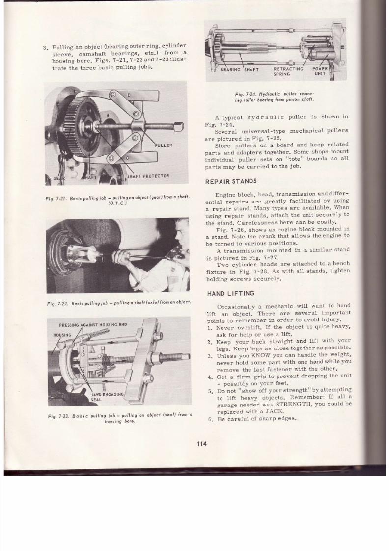
7/26/2019 Auto Service and Repair - Martin W. Stockel
http://slidepdf.com/reader/full/auto-service-and-repair-martin-w-stockel 114/224
3.
Pull ing
an
object
(bearing
outer
ring,
cylinder
s leeve,
camshaf t
bear ings,
etc ')
f rom
a
housing
bore.
Figs.
7 '2t ,7 '22
and
?-23
i l lus-
trate
the
three
basic
pull ing
jobs.
Fig.
7-21. Basíc
Pull ing
ob
-
pull ing on
obiect
gear)
rom
o
sho( '
(o.r .c .)
Fig.
7-22.
Bosic
pull ing
ob
-
pull ing
o
sholt
oxle)
rom
on
obiect '
Fíg.7-23.
Bosic
pull ing
iob
-
pull ing
on
obiecf
(seol)
l¡on
o
housinq
bore'
Fig.7 '24. Hydroulic puller remov'
ing rol ler
beoring
rom
pinion shoÍt '
A typical
hydraul ic
pul ler is
shown
in
Fí9.
1-24.
Several
universal-type
mechanical
pullers
are
pictured
in
Fig. 7-25.
Store
pullers
on a
board
and
keep
related
parts
and
adapters
together.
Some
shops
mount
indivídual
puller sets
on
"tote"
boards
so
al l
parts may
be carried
to
the
job.
REPAIR
TANDS
Engine
block,
head,
transmission
and
dif fer-
ent ial
repairs
are
greatly
facil i tated
by
using
a repair
stand.
Many types
are
available.
When
using
repair
stands,
attach
the
unit
securely
to
the stand.
Carelessness
here
can
be cost ly .
Fig.
7'26,
shows
an
engine
block
mounted
in
a stand.
Note
the crank
that
allows
the
engine
to
be
turned
to
varíous
Posit ions.
A transmission
mounted
in a
similar
stand
is
pictured
in
F. ig.
7
-27.
Two cylinder
heads
are
attached
to
a bench
fixture
in
Fig. ?-28.
As
with all
stands,
t ighten
holding screws securelY.
HAND
LIFTING
Occasionally
a
mechanic
wil l
want
to
hand
lif t
an
object.
There are
several
important
points to
remember
in order
to avoid
injury.
1.
Never
overlif t .
I f the object
is
quite
heavy,
ask
for
helP
or use
a
lif t .
2.
Keep
your
back
straight
and
lif t
with
your
legs.
Keep legs
as
close
together
as
possible '
3.
Unless
you
KNOW
you
can
handle
the
weight,
never
hold
some
part with
one
hand
while
yo u
remove the last fastener with the other'
4. Get
a
f irm
grip to
prevent
dropping
the
unit
-
possiblY on
Your
feet.
Do
not
"show
off
your strength"
by
attempting
to
lif t
heavy
obiects.
Remember:
If
all a
garage needed
was STRENGTH,
you could
be
replaced
with a
JACK.
Be careful
of
sharP
edges.
5.
Á
114
BEARTNG
SHAFT
RETRAC
PRESSING
GAINST
HOUSING
EN D
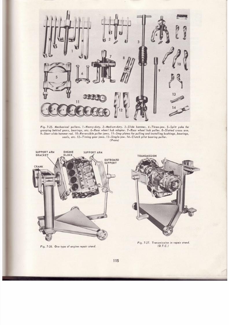
7/26/2019 Auto Service and Repair - Martin W. Stockel
http://slidepdf.com/reader/full/auto-service-and-repair-martin-w-stockel 115/224
ff,,g
P\
k
ás
Wr
4t
fi\
?
rg
Fig.7-25.
Mechonicol
pul lers,
l -Heovy-duty, 2-Medium-duty. 3-Slrde hommer,
4-Three-jaw,5-Spl i t
yoke
lo r
grosping
behind
geors,
beorings,
elc.
ó-Reo¡
wheel
hub
adopler,
7-Reor wheel hub
pul ler,
S-S/otted cross o¡m,
9-Sfio¡r s l idehomner
od, l0-Reversiblepul ler
lows.
l l -Step
platesforpul l ingondinstol l ingbushings,beorings,
seo/s,
elc, l2-Tining
geor
¡ows,
I3-Single-low. l4-CIutch
pi lot
beoring
pul ler.
(
P¡oto)
Fig,7-27.
Tronsmission
n repoir stond.
(o.T.c.)
SUPPORT RM
ENGINE
SUPPORT RM
Fig.7-26.
One type ol engine
epoir stond.
t ls

7/26/2019 Auto Service and Repair - Martin W. Stockel
http://slidepdf.com/reader/full/auto-service-and-repair-martin-w-stockel 116/224
HEAD
MOUNTING
BRACKET
Fig.7-28.
The cyl inder
heod
holding lix ture greo t ly
loc i l i to¡es
repoir
work.
(Storn-Vulcon)
SUMMARY
Mechanics
should
be
famil iar
with
lif t ing,
pu11ing,
pressing,
etc.,
tools
their
work
easier
and more
eff icient.
The tools
covered in
this
chapter
used
with extreme
caution.
Observe
al l
mended safety precautions.
varl0us
to
make
must
be
recom-
Hand
jacks
have
many
applications.
Floor
jacks
are
very handy
for
raising
and
posit ioning
ears.
Never
get
under
a car
supported
by
a
floor
jack
without f irst placing
jack
stands.
Be
careful
not
to
damage parts
when
lifting.
End
lifts
have
a fairly
high
reach
and
support
the
car
safely.
Make
sure the
safety lock
is in
posit ion.
Single
and double-post
lif ts
can be designed
to
engage
either
the frame,
suspension
system
or the
tires.
All have
advantages
and dis-
advantages.
Cars must be centered on the lif t and the
lif t ing
brackets
should
be
properly
and
securely
p laced.
Use
care
when
determining
tif t
points
to
avoid
chassis
distort ion
or
parr
damage.
Transmission jacks,
wheel
dollies
and
port-
able
cranes, facil itate
the
removal
and
instal-
lat ion
of
heavy parts.
Hydraulic presses
are
superior to
striking
too1s. Use
whenever possible
and use withcar.e.
The
shop
should
have
a
wide
selection
of
pulling
equipment.
Repair
stands for
engines,
transmissions,
etc., make the job faster, safer and easier. Al -
ways
place
unit
in
stand
securely.
SUGGESTED
CTIVITIES
1. Make
it
a
point
to receive
instruction
in the
use
of, and
practice
using,
all l if t ing,
press-
ing
and
pulling
equipment
in the
shop.
2. Maintain
a
file
of up-to-date
catalogs
cover-
ing
all types
of
shop
equipment.
Study
them
and
even
though
your
shop
may
not
have
al l
the
different
types, you
should
be
ful1y
in-
formed
as to what
is
available.
LUCK?
DON'T
YOUBELTEVE
T
The auto
shop, by
its
very
nature, presents
nurnerous
hazards.
Despite
this,
many
me -
chanics
work
at the trade
for
a lí fet ime
without
serious
injury.
Others,
however,
are frequenily
injured,
some
are kil led.
Is
shop
safety
then,
a matter
of luck?
Absolutely
notj The
major
things
that wiLl
keep you
in
one
piece
on the
job
are
an under-
standing
of
and respect for
the dangers
involved,
consistently
following
all safety
rules,
and
th e
development
of a
"think
before
you
act' ,
att itude.
On
each
anci
every
task,
apply these
sug-
gestions.
Apply
them
over,
and
over
and
over
until they become habits-
-habits
which may
someday
save you
from
serious
injury
or death.
OUIZ
-
Chopter
1. A
car srrppo"t. i
on
a
good
floor
jack,
well
placed,
is
safe
to work
under.
True
or
False
?
2.
Jack
contact
points
arenot importantaslong
as the
jack
gets
a
good
grip.
True
or
False
?
3. End
lif ts,
ifproperlydesigned,
provide
hold-
ing
power
suff icient
to
allow the mechanic
to
work
beneath
the
car without
iack
stands.
True or False ?
What
type
would
better
tend
itself
to drive
line
work
-
the
single-post
frame
or
th e
double-post
frame
lif t
?
The
drive-on
l i f t
is ideal
forpul l ingwheels.
True
or False?
Never_a
lif t without
checking
be -
neath
the
car.
Lift
height
can
safely be
varied without
get-
t ing
out from
under
the
car.
True
or
False?
Despite
the
type
of l if t ,
always
check
th e
_lock
before
gett ing
under the
car.
A
l i f t
should be
raised
and
lowered_.
Transmissions are best handled with a
Heavy
wheel
assemblies
are
easily handled
with
a_
When
moving
an object with
a
portable
crane,
keep the
Load
as_as
possible.
An
engine,
suspended
from
a
crane, is
safe
to work
on.
True
or
False
?
When
attaching
lif t
chains and
cables
with
4
E
¡7
B.
o
10 .
1t
t2.
13.
116
14.
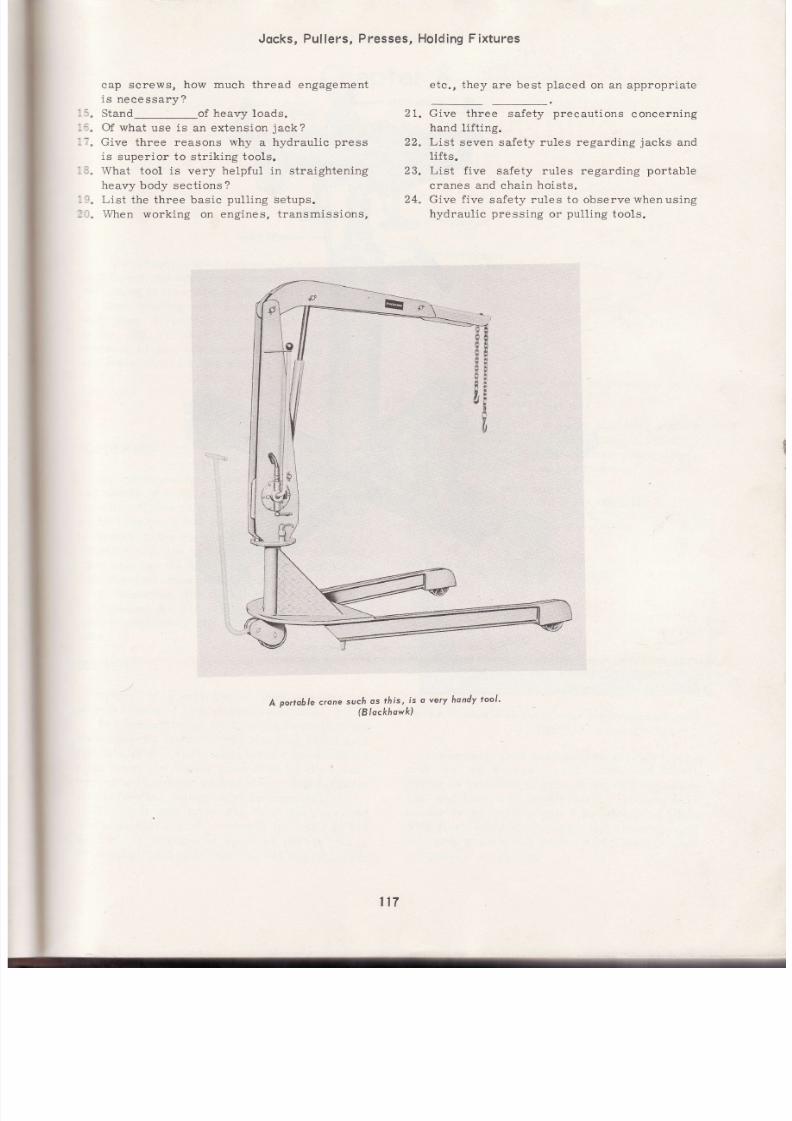
7/26/2019 Auto Service and Repair - Martin W. Stockel
http://slidepdf.com/reader/full/auto-service-and-repair-martin-w-stockel 117/224
Jocks,Pullers,Presses,
cap screws,
how much
thread engagement
is
necessary?
15.
Stand_of heavy loads.
16.
Of
what
use
is
an extension
jack?
li.
Give
three reasons
why
a hydraulic
press
is
superior to stríking tools.
18.
What tool is very helpful in straightening
heavy body sections ?
19. List
the three basic
pull ing
setups.
20. When
working on engines,
transmissions,
HoldingFixtures
etc.,
they
are best
placed
on an appropr ia te
Give three
safety
precautions
concerning
hand
lifting.
List
seven safety rules
regarding
jacks
an d
lift s.
List five
safety rules regarding
portable
cranes and chain hoists ,
Give
five
safety rules to observe whenusing
hydraulic
pressing
or
pull ing
tools.
2L.
22
23.
24.
.i:
A
porrobre
-. ',?l;' ;1,:;i;
vervhondv
oot'
u7
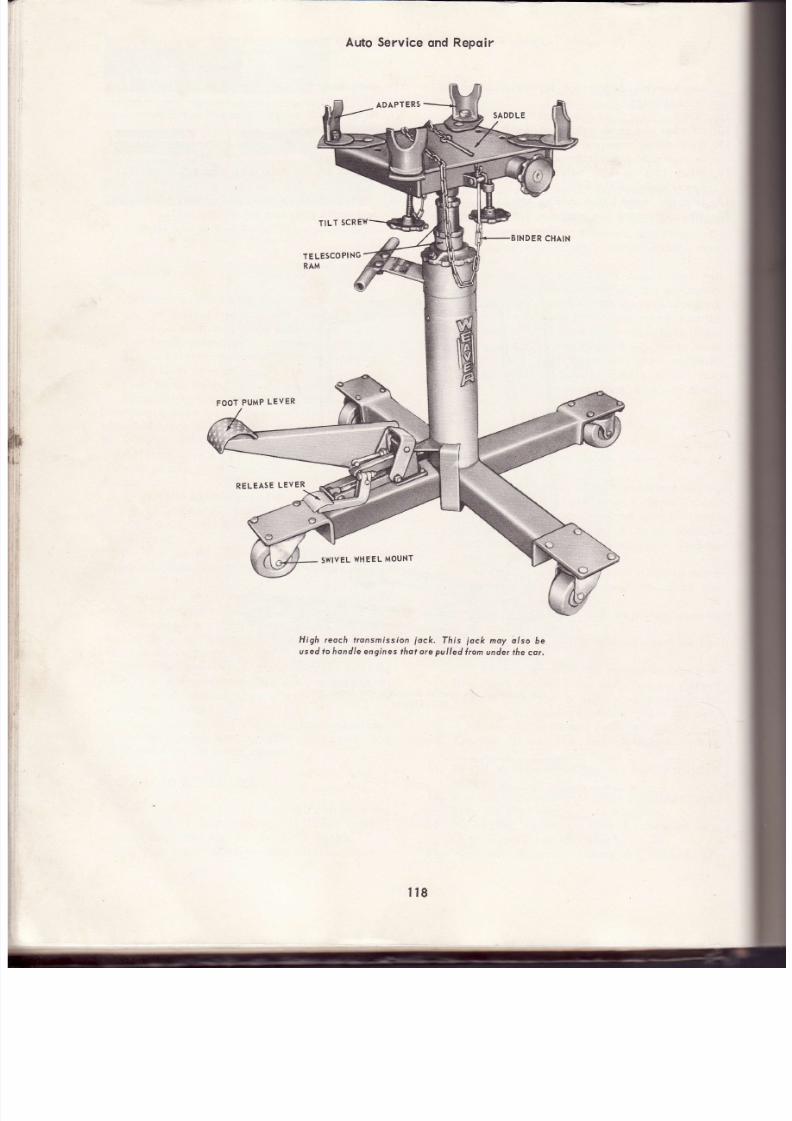
7/26/2019 Auto Service and Repair - Martin W. Stockel
http://slidepdf.com/reader/full/auto-service-and-repair-martin-w-stockel 118/224
FOOT
PUMP
LEVER
RELEASE
EVER
Auto
Service
ond
Repoir
TILT
sC R
TE
LESCO
I
NG
RAM
SWIVEL HEEL OUNT
High reoch f¡onsmíssíon
iock.
This
jock
noy o/so
be
used o rondle ngines
hotore
pul led
¡on
under he
cor
l r8

7/26/2019 Auto Service and Repair - Martin W. Stockel
http://slidepdf.com/reader/full/auto-service-and-repair-martin-w-stockel 119/224
SOLDERI
G,BRAZING,
ELDING
CRACK ETECT¡ONND REPAIR
This chapter
is designed
to
províde
basic
:echniques,
machine
operat ions
and
safety rules
pertai.ning
to soldering,
welding
and brazing.
Most
welding
and brazing
is confined
to the
body
shop.
However,
you
will
f ind
that welding
skil ls
can be
used
on many
dif ferent
jobs.
Students
of auto mechanics
should take
at least
cne basic course in the welding f ield.
USE
CAI1E
WHEN
WELDING,
HEATING
OR
:: 'TTING.
FiRE
OR EXPLOSiON
CAN
OCCUR.
:. :EP
AWAY
FROM FUEL TANKS,
BATTERIES
.:. \D
OTHER
FLAMMABLE
ITEMS.
sOLDERING
Soldering-can be defined as the
act of joining
:wo
pieces
of metal through
the use
of a lead and
::n
alloy. There
is
no actual fusion
(melt ing
to -
Eether) involved. The
solder, when
the base metal
:s
heated
to the
correct temperature,
seems to
o'terally
dissolve a minute skintt on the metal.
--pon
eooling, the
solder and
skint 'amalgamate
rmix
together)
thus
forming
atightbond,
Fig.
8-1.
In
soldering,
the
pieces
to
be
joined
should
:--t
together
as
closely as
possible.
The
less
solder
separat ing
the
parts,
the stronger the
-
oint.
SOLDER
Solder
is
a mixture
of
lead
and tin
plus
'ninute traces
of
zinc,
copper,
aluminum,
etc.
The
proportion
of
tin
to lead affects
both the
:oelting point (poi.nt at which solder becomes a
i':11
liquid)
and
the
plastic
range
(temperature
span
from
the
lowest
point
at which
the solder
becomes
mushy
or
plastic,
to the highest
point
;ust
before
the
plastic
mixture
liquifies).
You
will
note from
Fig. 8-2,
that
pure
lead
:nelts
at 621
deg.
F. and
pure
tin melts
at 450
Ceg.
F..
A
mixture
of
about
63
percent
tin
to
7 percent
lead
will
melt
at 361 deg.
F.
Study
Fig.
8-1.
7ñe solde¡ ond metol skin
omalgomote
pon
cooling
lhus Íorming
o tight
bond.
the
chart in Fig. 8-2,
and
note
how
temperature
and
plastic
range is
affected by alloying
in
differ-
ent
proportions.
A
solder that
has
awideplastic
range
is
required for
ear body work.
Chapter
621
Fig.8-2.
Tin-leod
olloy plost ic
ronge
ond melt ing
point
chort.
(Keste¡)
Comrtronly
used solders
are 40l60
(40
per-
cent t in, 60
percent
lead), 50/SO
and
60/40.
Solder is
available in
bars or ingots for
plumb-
ing,
and body
and
fender
work. Flux
core
wire
solder
(wire
solder
with
a hollow
center
f i11ed
with f lux),
solid wire
solder, and solder
ground
into f ine grains,
and mixed with f lux,
are used
for general
soldering.
TIN-LEAD
FUSION
IAGRAM
',2f
r
''r
+ o/ ?a/
\a/
4a/
.a/ 70,
ao so/ +
rrñ
-EAD
+
/eo /3a /7o /6a /5o /aa /ra /2a / a +
-F^a
\
t
tu
76
,35.
\
I
&
I
I
36' i
}\
t \
I
PLASTIC
I
] .
\
UID
Q10 -
399.
-
PLAf
{t
iTrcf
36r'
l t9

7/26/2019 Auto Service and Repair - Martin W. Stockel
http://slidepdf.com/reader/full/auto-service-and-repair-martin-w-stockel 120/224
Fíg.8-3.
Hondy
size
solderíng
irons. A Light
duty
B-Medium
duty.
Q, Heovy
uty.
(Snop-On
ools)
SOLDERING
LUX
Soldering
obviously
heats the
metal andin
so
doing
accelerates
oxidization
(surface
of the
metal combining
with
the
oxygeninthe
air).
This
leaves
a
thin
film of
oxide
on the
surface
that
tends
to reject
solder.
It is the
job
of the
flux
to
remove
this
oxide,
andprevent
the
reoccurrence
during
the solder lng
Process.
Chtoride
or
acid
flux is excellent
for
use on
radiators
and
other
solder ing
where
acorrosive
and electrical
conductive
residue
(f1ux
remaining
on the work after soldering) is not harmful. Ho t
water should
be
used
for cleanup
after
solder-
ing.
BE SURE
TO KEEP
ACID
FLUX
OIIT OF
YOUR
EYES.
Organic
flux
is somewhat
l ike
the
acid
type,
but
is less corrosive
and
the
f lux residue
be-
comes
flakey
and
soft,
and can
be
readily
re -
moved
by
dusting,
tumbling
or
wiping
with
a
damp
cloth.
I ts ef fect iveness
is lost
i fsubjected
to susta ined
high temPeratures.
Rosin
or
resin
type
f lux
MUST
BE
USED
FOR
ALL
ELECTRICAL
WORK.
The
residue
will
not cause
corrosion,
nor
will
it conduct
electricity. The residue may be rernoved
with
kerosene
or
turpent ine.
A
special
f lux
is required
for
soldering
aluminum.
SOLDERING
RONS
The
solder ing
iron,
somet imes
cal led
acop-
per, should
be of
ample
size
for
the
job.
An
iron
that
is too
9ma1l
wi l l
require
excessive
time
to
heat the
work and
may
never
heat
i t
properly.
The
proper sizé
iron
wil l
bring
th e
rnetal up
to
the
correct
soldering
heat
(around
525-575 deg. F.) quickly
and
will
produce a
good
job.
Plain
irons or coppers
(must
be
placed
in a
gas
flame
or
in an
electric
furnace
to
heat)
range
in si.ze
from around
1/2 lb.
forlight
work,
up tci
several
pounds
for
heavier
tasks.
Electric
irons are
fast and
eff icient.
A
100-
watt s ize
is
recommended
for l ight
work,
a2OO-
watt
size
for
medium
work and
a
35O-watt
iron
for heavier
work.
(Wattage
will vary
-
these
Fig.8-4.
A solderíng
un
such
s
?his
wo¡ks osf
(SnoP On
ools)
are
approximate
size
recommendations.)
Se e
Fig.
B-3.
For electrical
wiring
a soldering
gun as
shown
in
Fig. 8-4
is
ideal.
The t ip
reaches
soldering
heat
in a
matter
of a
few seconds.
CLEANING ORK
A1l
t races
of
paint , rust , grease, scale, etc ,
must
be
removed.
The
grinding
wheel,
wire
brush,
f i le,
steel
wool, emery
c1oth,
cleaning
solvent
etc.,
are
all
useful
in
preparing
th e
surface
for soldering.
Remember
that
GOOD
SOLDERING
REQUIRES
CLEAN,
WELL-
FITTED SURFACES.
TINNING
THE IRON
The
soldering
iron t ip
is
made of
copper
and
wil l
through
the
solvent
action
of solder
an d
prolonged
heating,
pit
and corrode.
An
oxidized
or
corroded
tip wi l l not satisfactorily transfer
heat
from the
iron
to the
work, and
should
be
cle-aned
and t inned.
Use a
file and
dress
the
ti p
down
to the
bare copper.
File the
surfaces
smooth
and
f1at.
See
Fie.
B-5.
\
TIP
BADLY
CORRODED
FILED
CLEAN
AND
SMOOTH
Fi le
t ip surfoces
llot
ond smooffr.
is .8-5.
Then,
plug
the
iron
in. When
the
tip color
begins
to change
to
brown and
li ght
purple, dip
the
tip
in
and
out of
a can
of
soldering
flux
(rosin
core)
and
quickly
apply
rosin
core
wiré
120

7/26/2019 Auto Service and Repair - Martin W. Stockel
http://slidepdf.com/reader/full/auto-service-and-repair-martin-w-stockel 121/224
Solder ing,
Brozing'
solder
to all
surfaces.
If
no
paste
flux
is
avail-
ab1e,
rosin
core
wire
solder
wil l
do'
However'
dipping
the
tip
provides
a
faster
and
usually
better
tinning
job.
The
iron
must
be
at
operating
heat
to
ti n
properly.
When
the
iron
is
at
the
proper
tem-
perature, solder wil l melt
quickly
and
flow
freely.
NEVER
TRY
TO SOLDER
UNTIL
TH E
IRON
IS
PROPERLY
TINNED.
See
Fig '
8-6'
I f
during
tinning,
a
surplus
of
solder
adheres
to
the tip,
wipe
off
the
excess
with
a
rough
tex-
tured cotton
rag.
Welding,
Crqck
RePoir
WIRE
SOLDER
Fis.
8-8. Apply
soldet
tT 'J;01
the
iron
where
f conrocts
the
flux
where
i t
wil l
do
the
most
good'
Flowing
solder
at
this
point
wil l
also
provide
a
mechan-
ical
bond
between
iron
and
work
that
wi l l
speed
up
heat
transfer ,
Fig.
8-8.
WORKMUSTBE HOT
Pieces
to
be
joined
by
soldering
should
be
heated
so
the
solder
is
melted
by
heat
in the
metals
to
be
soldered
together.
When
this
is
done,
solder
wil l
f low
readily
and
a
good
job
wil l
result.
If
the
solder
melts
slowly
and
is
pasty
looking,
the
work
is
not
hot enough'
If
using
a
gas flame
to
heat
the
parts,
be careful
to
avoid
overheating
SWEATING
Two
pieces
may
be
joined
by
tinning
the'
contact
surface
of
each,
placing them together
and
applying
heat.
When
the
tinning
metal
melts'
the
pieces are
held
inf i rmcontact.
This
process
called
sweating,
produces
a strong
union'
if
proper lY
done.
See
Fig.
B-9.
SOLDERING
W¡RE
SPLICES
Apply
the
tip
flat
against
the
splice'
Apply
rosin
core
wire
solder
to
the
f lat
of
the
iron
where
it contacts
the
wire.
As
the
wire
heats'
the
solder
wi l l
f low
throughthe
spl ice,
Fig '
B-10'
DO {OT vlOVEWORKUNTILCOOL
When
joining
two
or
more
pieces
by soldering'
be
careful
not
to
disturb
them
until
the
solder
has
set
(cooled
to
the
solid
state)'
If
they
are
moved
rvhile
the
solder
is still
in a
pasty
state'
fracture
lines
wil'I
be set
up
that
will
produce
a
weak
joint.
121
I
f
¡
t
u
x
¡
Fig.8'6.
The
ip
must
e
properly
inned'
Some
shops
use
a
block
of
sal
ammoniac
to
aid
in
tinning.
The
hot
iron
is
rubbed
on the
block as
solder
is aPPlied.
HOLDING
HE
IRON
The
iron
must
be
held
so
that
the
flat surface
of
the
tip
is
in
full contact
with
the
work'
This
wil l permit a
maximumtransfer
of
heat,
Fig'
B-7'
APPLY
SOLDER
O
EDGE
OF
IRON
Apply
the
wire solder
at
the
edge
of
the
iron
where
it contacts
the
work.
This
wi l l
release
WITH
WORK
RIGHT
CORRECTLY
TINNED
TIP IN
FULL
CONTACI
Fig.8-7.
Hold
the
tip
l lot
ogoinsr
he
work'
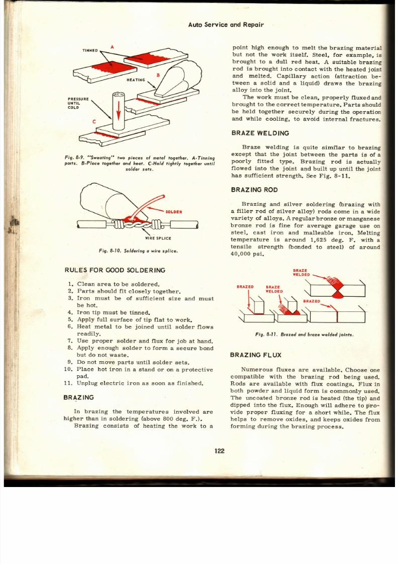
7/26/2019 Auto Service and Repair - Martin W. Stockel
http://slidepdf.com/reader/full/auto-service-and-repair-martin-w-stockel 122/224
Fig.8-9,
Sweof ing
fwo
pieces
ol
me¡ol
together.
A-Tinning
ports.
B-Place together
an¿ heot.
C-Hold
tightly logether
unti l
so/de¡ sets.
WIRE
PLICE
Fig.
8-10.
Solder ing
wire spl ice.
RULES
OR
GOOD OLDERING
1. Clean area
to be soldered.
2.
Parts
should f it
closely together.
3. Iron must
be
of suff icient
size and must
be hot.
4. Iron
tip must
be t inned.
5. Apply full
surface
of tip flat to work.
6. Heat
metal to
be
joined
until
solder f lows
readily.
7.
Use
proper
solder
and flux for
job
at
hand.
B.
Apply
enough
solder to form
a secure
bond
but do not waste.
9. Do not
move
parts
until
solder sets.
10. Place hot iron in a stand or on a protective
pad.
11.
Unplug
electric iron as
soon as
finished.
BRAZING
In
brazing the
temperatures involved
ar e
higher
than
in
soldering
(above
800 deg. F.).
Brazing
consists of heating the work
to a
Auto
Service
qnd
Repq¡r
point
high
enough
to melt
the
brazing material
but not the
work itself.
Steel,
for
e*ample,
is
brought
to
a dull
red heat.
A suitable
brazing
rod is
brought into
contact with
the
heated
joint
and melted.
Capillary
action
(attraction
be-
tween a
solid and a
liquid)
draws
the
brazing
alloy into the joint.
The
work
must
be
clean,
properly
fluxedand
brought to the
coruect temperature. Parts
should
be held
together
securely
during the
operation
and while
cooling,
to avoid
internal fractures.
BRAZE
WELDING
Braze welding
is
quite
simr'lar
to brazing
exeept that
the
joint
between
the
parts
is
of
a
poorly
fitted
type.
Brazing
rod is
actually
flowed
into
the
joint
and
built up
until
the
joint
has sufficient
strength.
See Fig. 8-11.
BRAZING OD
Brazing
and
silver soldering
(brazing
with
a
filler
rod
of silver
alloy) rods
come in
a
wide
variety of alloys. A
regularbronzeor
manganese
bronze rod is f ine
for
average
garage
use on
steel,
cast
iron
and malleable
iron. Melt ing
temperature
is around
1,625
deg. F. with
a
tensile
strength
(bonded
to steel)
of around
40,000
psi.
Fig.
8- l I .
B¡ozedond braze welded
joints,
BRAZING
LUX
Numerous fluxes are. avai.lable. Choose one
compatible with the
brazing
rod
being
used.
Rods
are available
with ftux
coatings.
Flux
in
both
powder
and
liquid form is
commonly used.
The
uncoated bronze
rod
is heated
(the
tip)
an d
dipped
into the flux.
Enough
will
adhere to
pho-
vide
proper
fluxing
for
a
short
while.
The flux
helps
to remove
oxides, and keeps
oxides from
forming
during
the brazing process.
122

7/26/2019 Auto Service and Repair - Martin W. Stockel
http://slidepdf.com/reader/full/auto-service-and-repair-martin-w-stockel 123/224
Solder ing,
Brozing,
SOURCES
F HEAT
FOR BRAZING
A
Bunsen
burner,
b lowtorch,
propane
torch,
:xyacety lene
torch, carbon arc, etc .,
wi l l
a1l
:roduce
suff ie ient
heat for braz ing and
braze
,r
elding.
Propane
an-d oxyacetylene
torches
rre
wel l sui ted
for
the
job
and are
general ly
:i ai.lable in the shop.
The
acety lene torch,
Fig. B-12, is
s imi lar
:o
a
propane
torch. A regulator
is
attached
to
a tank
of
gas,
the tank valve
is
opened
and set
:cr
the desired f low.
As
this torch ut i l izes
rxygen
from the
air, only one
tank
(acetylene)
:s
required.
Several
t ip
s izes
are avai lable.
A regular oxyacetylene outfit
(uses
a tank
:1
oxygen
and a
tank
of acetylene)
is shown
in
aig.
B-13.
Oxyacety lene
flame temperatures
:rceed
6,000 deg. F.
See
Fig.
B-13.
TIP CLEANER
BRAZING NDWE
TIP
ATTACHMENTS
Welding,Crqck
Repoir
Fig. 8-12.
So/de¡
broze ki t.
(Morquette)
YGENCYLINDER
AUGE
TIP PRESSURE
ACETYLENE
GA
TANKCONNECTION
LIGHTER
GOGGLES
Fig.
8-13. Oxyocetylene
welding,
brozing ond cutt ing outl i t .
(Morquel te)
ETY
LEN E
INDER
GAUGE
ACETY
LEN E
REGULATOR
MIXER
VALVE
FLAME
CONTROL
TANK
CONNECTION
PRESSURE
DJUST
ITTINGTO ATTACH
TO
MIXERHANDLE
ATTACHMENT
XYGEN
CONTROL ALYE
CUTTING TTACHMENT
CUTTING
IP
123

7/26/2019 Auto Service and Repair - Martin W. Stockel
http://slidepdf.com/reader/full/auto-service-and-repair-martin-w-stockel 124/224
Auto
Service
ond Repoir
BRAZING
ECHNIOUE
Select
a
tip
size
appropriate
tothe
work.
The
tip
size
chart,
Fig.
B-14,
wil l give
you
an in_
dication
of
size
in
relation
to metal
thickness.
Note
the
recommended
gas
pressures.
APPROXIMATE
GAS
PRE5SURES
FOR
OPERATINC
AIRCO
WELDING
TORCHES
Tip
No.
Mixer
Thickness
of
Metal (In. )
Oxygen
Pressue
(ps i)
Pressu¡e
(ps i)
5
7
7
Fig.8J4,
I ip
size ond pressure
chor .
1231561
t -7
1-7
t -7
1-7
t -7
t_7
ó-10
l/16
3/32
l. /8
3/16
1./1
5/16
3/ B
and
clear;
a tri f le
more
heat
wil l
be
sufficient-
Touch
the
fi l ler
wire
to
the
work.
When the
heat
is
eorrect,
it
wi l l
mel t
and
tin
the parts.
Use
the
tip
to
guide
the
flow
of
metal
(tinning
action
fol lows
the
heat).
Make
sure
the
fi l ler
enters
the
joint
ful l
length
and
that
it
t ins
properly.
TIP
DISTANCE
AND
ANGLE
IS IMPORTANT
The
distance
the
torch
tip
is
held
from
the
work
affects
the
rate
and
extent
of
heating.
Parts
with
a low
melting
point
wil l
require
holding
the
tip
further
from
the
area
to
be
brazed,
Fig.
8-1?.
By
holding
the
tlp
at
an
angle,
tr ig.
B_1g,
the
work
is
kept
at
brazing
temperaturé
with
minirnum
danger
of
overheating.
Note
how
th e
distance
is
varied
to
suit
the
work,
while
th e
angle is maintained.
KEEP
TIP
IN MOTION
Keep
the
tip
in
motion
to
spread
the
heat. I f
the
flame
is
kept
in
one
spot
too
long,
over_
heating
may
result.
A
circular
motion,
Fig.
B-19,
is
desirable.
The
size
of
the
ci rc le
should
be
decreased
as
the
joint
becomes
heated.
When
brazing
temperature
is
reached,
the
circles
should
be quite
small.
Using
a
zigzag
motion
during
the
application
of
the
welding
rod
is
also
satisfaetory.
BRAZE
WE
DING
ECHNIOUE
In
braze
welding,
a
groove,
fi l let
or
slot is
fi l led
with
nonferrous
fi l ler
metal,
having
a
melting
point
below
that
of
the
base
metals,
bu t
above
800
deg.
F.
The
fi l ler
metal
is
not
dis_
tributed
by
capil lary
attraction.
The
technique
used
for
braze
welding
is
similar
to
brazing.
Once
the
brazing
rod
has
flowed
out
and
the parts
tinned,
the
heat
should
be
careful ly
control led
so
the
braze
metal
ca n
be
buil t
up
to
the
desired
thickness. The ro dmeta1,
as i t
is
fed,
must
mixwiththat
added
be_
fore
but
must
not
cause
the
buildup
to flow.
Se e
Fig.
B-20.
RULES
OR
GOOD
RAZING
1.
Work
must
be
clean
and
well
f i tted.
2.
Use
a
t ip
and gas
pressures
in
keeping
wi th
the
job.
00 0
00-t
00- l
t /64
t/32
Fig.8-15.
Corburiz ing,
neut¡ol
ond
oxidiz ing
Í lames.
Adjust
the
torch
to produce
a neutral
or
stightly
carburizing
(excess
acetylene)
flame,
Fig.
8-15.
With
the parts
CLEAN,
CLOSELY
FITTED
(ideal
joint
gap
for
braz ing
is
.0015
-
.003),
FLUXED
and
FIRMLY
HELD,
apply
heat
to
th e
joint.
Use
a brushing
motion
of the
torch
tip
as
shown
in
Fig.
B-16.
Watch
the
flux.
Wben
it
starts
to
turn
watery
NEUTRAL
oxtDtzrNc
BRUSH
MOTION
OF
TORCH
XY -ACETYLENE
TORCH
FILLER
METAL
APPLIEO
FROM
S
ENO OF
JOINT,
TORCH
MOVEO
IN
THIS
DIRECTION.
JOINT
Fig. 8-16.
Heot
joint
pr ior
o
opplying
brazing
mater ial .
When
hot,
stort opplying
liller
metal
from
one
edge
and
use rfie
brushing
mo-
tion
of
the
llome
to
drow
materiol
olong
ond
ínto the
¡oint.
(ATRCO)
124
ACETY
EN
E
FEATH
ER

7/26/2019 Auto Service and Repair - Martin W. Stockel
http://slidepdf.com/reader/full/auto-service-and-repair-martin-w-stockel 125/224
Soldering,
Brozing,
Fig.8-17,
f lre disfonce
Írom t ip
to work o(Íects
heot
t¡onsler.
Fig. 8-18.
Hold
to¡ch tip ot on ongle
to the
work.
(Brozing.)
Welding,
Crqck Repoir
3.
Use
a
neutral
or slight ly
reducing
(carbu-
rizing) f lame.
4.
Keep
tip in motion.
5. Hold
the t ip
at an angle
to the work.
6.
Heat may
be
controlled
bychangingdistance
from
tip to work.
7.
Braze metal
should be
suited to
the
job.
8. Use a good flux.
9.
Braze
metal
must
penetrate
the
joint
an d
tin
the surfaces.
10.
Parts
must
be held in
posit ion
and not
dis-
turbed
until braze metal
sets.
11.
Avoid
overheatins,
GASWELDING
Unlike
brazing, welding
is
a
fusion process.
A
port ion
of the metal
of eaeh
part
is melted.
The
melted
areas f low
together
and upon
cool-
ing
form
one solid
part.
Fil ler
rod is
often
added during the process.
PREPARING
HE JOINT
Thin
metal
l l32 in.
or l ess, is
of tenf langed
to
protect
against
heat warpage
-
A,
Fig. B-21.
Parts
not
exceeding
1/B
in.
may
be
welded
by
using
a square edge-butt
joint
-
B.
When
-metal
th ickness
ranges f rom
around
1/8
-
3/B in. ,
a
V- joint
is
used
-
C. Parts
over 3/8 in.
ar e
usually
prepared
with
a
double
V-joint
-
D,
Fig.
B-21.
Both
the
joint
and the
immediate
area must
be
cleaned
of rust, scale,
paint,
etc.
FLANGE
BUTT
CORRECT
\
Éia)
I
r t
r l
F ig.8-19. Keep
tñe
torch t ip
in motion.
Brozing.)
FLAME
TOO
HO T
AND
TOO
CLOSE
WRONG
\
IJ
htt
t f i
t{ i
)fd.
ERAZE
BUILDUP
FLOWING HROUGH
JOIN
Broze
welding.
A-Corect. 8-7oo ñot. Nofe
fiow
6roze
melol 6ose
soos.
JOINT
--¿::--/::
i lbü
Fig,
8-21.
Yleld
¡oint
preparotion
n vo¡ious
hicknesses
ol me¡ol.
USE
NEUTRAL FLAME
Use a neutral f lame for gas weldi.ng. Th e
neutral
f lame wil l permit
smooth,
dense welds
of high
strength. There
will
be no foaming,
sparking,
etc.
A
carburizing
f lame
(excess
acetylene) wiI I
cause molten
metal
to
pick
up carbon from
th e
flame. This
causes the metal
to boil
and
upon
cooling,
to become
brit t le.
BRAZE
MATERIAL
BUILDIÑG
UP
IN
JOINT
O. K.-LESs
HEAT
F;s.
8-20.
t25

7/26/2019 Auto Service and Repair - Martin W. Stockel
http://slidepdf.com/reader/full/auto-service-and-repair-martin-w-stockel 126/224
An
oxidizing
flame
excess
of oxygen)
will
cause
the metal
to
foam and send off a shower
of sparks.
The
excess oxygen combines
withthe
steel causing
it to burn.
The weldwillbe
porous,
weak
and
brittle.
TIP SIZESELECTION
Torch
tip size
must be
suited
to the
job.
Fig. 8-14,
gives
typical tip sizes and
gas pres-
sures
for
different metal
thicknesses.
WELDING ECHNIOUE
BACKHAND
ETHOD
The t ip should be
directed back into the
molten
puddle,
away
fromthe direction
of travel.
The
rod
is held between the f lame and
weld.
ACKHAND
Fig.
8-22.
Forehond nd hoclchond
elding ecñnigues.
lAiRCO)
When
the base metal
metal
of
parts
being
joined)
melts
and
forms
a
puddle,
the filler
rod
is
added as
the
weld
progresses.
MELT THE
ROD
BY
INSERTING THE END INTO THE
PUDDLE.
Do not
hoLd the rod above the
puddle
and
allow
it to melt
and drip
ín.
THE
INNER FLAME
CONE MUST NOT
TOUCH
EITHER THE
ROD OR THE PUDDLE.
Move the flame
along the
weld in
a steady
fashion,
causing the base metal
to
reach
th e
fusion
state
just
ahead
of
the
puddle. The
weld-
Auto
Service ond
Repq¡r
ing
rod
can be
moved
from
side to
side,
in
small circles or in half-circles. THE
WELD
SHOULD
PENETRATE
THROUGH THE
JOINT.
Fig.
8-22
shows both the forehand,
and back-
hand, techniques.
OXYACETYLENEUTTING ORCH
The
cutting torch finds
many
uses in the
auto shop. In
an oxyacetylene
eutting torch,
a
preheating
flame is
maintained,at
the
tip through
small
orifices or openings
around
the
center
orifice.
The
preheating
flame is
held
close
to
the work
at
the
point
where
the
cut
is
to start.
When
the spot
has been
heated
to a bright
eherry
red
or
hotter,
depress
the
oxygen
jet
lever.
When the stream
of
pure
oxygen strikes
the heated
area, it will
cut
burn)
through
the
steel.
As soon as the cut starts, move the torch
along
the work. Move
as
rapidty
as the
cutting
will
allow. Keep
the
oxygen lever fully
de-
pressed.
If
the
cutting action
stops, release the
oxygen lever
and
with
the
preheat
flames
they
burn
continuously),
preheat
again.
Holdthe
toreh
tip at right angles to the work with
the
preheat
flames
just
clear of the
surface,
Fig.
8-23.
PREH
EATING
THE
EDGE
+
PREHEAT
FLAMES
JUSTCLEAR
WORK
CUTTING
STREAT
Fig. 8-23. Hold ¡he
cutting tip at right ongles
to tlre work
so
preheot
flomes
just
clear the work.
Note how the
eutting
toreh
removesanarror
kerf
cut)
and how
the molten metal
stag)
is
blown
out
from
beneath
the work, Fíg. 8-24.
ill
r
{
126

7/26/2019 Auto Service and Repair - Martin W. Stockel
http://slidepdf.com/reader/full/auto-service-and-repair-martin-w-stockel 127/224
SETTING POXYACETYLENE
OUIPMENT
Keep both
the
acetylene
and oxygencylinders
supported securely.
The acetylene cylinder
should
be in the
upright
position
to
prevent loss
of acetone
(acetylene
cylinder
is filled
with
Fig.8-24,
Torch
cutt ing
ocfion.
Nole
use
of
gloves.
(Lincoln
Electríc
Co.)
WELDING
TORCH
OXYGEN
HOSE
CONNECTION
CYTINDER
RESSURE
GAUGE
WORKING
PRESSURE
GAUGE
WORKING
PRESSURE
GAUGE
CYTINDER
RESSURE
T GAUGE
OXYGEN
HOSE
ACETYLENE
VALVE
WRENCH
ACEIYTENE
REGUTATOR
ACETYLENE
HOSE
TWIN HOSE
OXYGEN
REGUTAIOR
Solder ing,
Brozing,
Welding,
Crock
Repoir
acetone
soaked
porous
fil ler material).
Keep
cylinders
away
from heat and
flames.
Pro-
tective tank
valve caps
must be in
place
when
cylinders
are stored.
Mark
empty
tanks
with
the
letters
MJ¡ tsig.;8-24AA,
id.ustrptes
ho w
tankS
or
,cyünders
are--attached
to
the welding
setup.
REGULATORS
The
oxygen
regulator
has a right-handthread
and
the acetylene
a left-hand
thread.
This
pre-
vents
instaliing
the regulators
on
the wrong
cylinders.
Fig.8-24A.
Typicol
oxygen regulo-
lor.
Nole high reoding
cylinder
gouge.
The
regulators
reduee cylinder
pressures
to a controlled
and useable
amount.
Figs-8-?44
and
8-248, i l lustrate
typical
regulators;
Note
the cylinder
and
hose
fittings.
The right-hand
gauges
read
cylinder
pressure,
while
the left-
hand
gauges indicate
tip operatingpressure.
Ti p
pressure is varied by adjusting the handles.
Before attaching
regulators
to
cylinders,
crack
(open
slightly)
the valve
on each
cylinder
a small
amóunt
for
a
second
to
blow out
dust or
other
foreign
material.
Do not crack
the
acety-
lene
near any
open
flames or
near
a
welding
operation.
Attach
the
regulators
to their
re -
spective
tanks.
Tighten
gently.
NEVER
USE
t
\
I
tr=-p
sP^.RKLIGHTER
3E:ú3
APPARATUS
IVTENCH
LINDER
CONNECTION
(RIGHT.HAND
HREAD)
HOSE
CONNECTION
Irr rKErruKt
i i r ló i ¡_. i IXOTHREAD)
CONTROLHANDLE
IP
PRESSURE
É
u
A
=
J
I
z
u
o
x
o
I
u
z
U
J
F
E
I
Fig.
8-24AA. Oxyocetylene
weldíng sefup.
(ATRCO)
127

7/26/2019 Auto Service and Repair - Martin W. Stockel
http://slidepdf.com/reader/full/auto-service-and-repair-martin-w-stockel 128/224
HOSECONNECTION
LEFT.HAND
HREAD)
Fig. 8-248.Typícol
ocetylene egulotor.
connect lons.
TIP
PRESSURE
CONTROL
HANDLE
Note le Í t -hond
thresd
OIL
ON
REGULATORS.
DO
NOT HANDLE
GA S
WELDING
EQUIPMENTWITHOILY
ORGREASY
I
HANDS,
AND DO
NOT WEAR
OIL
SOAKED
CLOTHING.
OiI,
in the
presence
of
pure
oxygen,
becomes highly
f lammable.
Back out the
pressure
contro l
handle oneach
regulator
counterclockwise)
unt i l
f ree.
ATTACH HOSE
Attach
hoses to the regulators.
The acetylene
hose is normally red
and the oxygen
green.
Aeetylene
fit t ings
are
left-hand threads
while
ATTACH TORCH
MIXINGHANDLE
The
torch
mixing handle should
be attachec
to the
hose
end. Do
not overt ighten
either
mix-
ing
handle
or
regulator
end hose connections.
Where
rubber
O-r ing
seals
areused,
handtight-
ening is suff icient. Note the oxygen and acet-
ylene mixing valves, Fig.
B-25.
ADJUSTING
AS
PRESSURE
After insta l l ing
the desired t ip ,
MAKE
SURE
THE REGULATOR
PRESSURE
CONTROL
HAN-
DLES ARE BACKED
COUNTERCLOCKWISE
COMPLETELY
OFF. THE
TANK VALVESMAl-
THEN BE OPENED - VERY SLOWLY.
Open the
ACETYLENE
VALVE about
ONE TURN. Ope:
the
OXYGEN
valve ALL
THE
WAY
in order
tc
prevent
leakage
around the valve stem.
Leave
the ACETYLENE WRENCH in place onthevalve
to
facilitate an emergency
shutoff
-
if requirec
at
any t ime.
SHUT
the
ACETYLENE
mixing valve.
OPE\
the
OXYGEN mixing valve.
Turn
the
OXYGE\
regulator
handle in
clockwise)
until the desirec
working
pressure
is obta ined
read
low
pressure
gauge). PURGE
clear
the hose of air or othe:
gases)
the oxygen
hose line by
allowing
oxyge:.
to f low
from
the
hose momentarily.
SHUT
of :
the
oxygen
mixing valve.
OPEN the acetylene mixing valve
oxyger.
valve
off) and adjust acetylene
regulator to
de -
sired pressure. Fol lowing purging, close acety-
lene mixer valve.
PURGING
LINES IS
VERY
IMPORTANT.
FAILURE TO DO
SO
CANALLOWACETYLENE
TO ENTER THE OXYGEN HOSE AND
VICE-
TYL EN
E
CYLINDER
PR
ESSURE
GAUGE
CYLINDER ONNEETION
LEFT-HAND
HREAD)
TIP
PRESSURE
GAUGE
Fig.
8-25. Torch nixing
hondle wi th
o
t ip ot toched.
Morquet le)
oxygen
fit t ings are right-hand.
When
using
th e
equipment,
keep hoses away
from hot sparks,
f lame,
oí1,
grease,
etc.
Avoid kinking, and coil
when f inished workins.
VERSA.
THIS OF COURSE, CREATES
A
COM-
BUSTIBLE
MIXTURE TNSIDE
THE
HOSE AND
CAN CAUSE
A
FLASHBACK
FIRE
BURNING
INSIDE
THE HOSE).
MIXERVALVE
128

7/26/2019 Auto Service and Repair - Martin W. Stockel
http://slidepdf.com/reader/full/auto-service-and-repair-martin-w-stockel 129/224
Soldering,
Brozing,
LIGHTINGTORCH
Open the acetylene
mixer
valve
a small
amount while
operating
a seratcher or
spark
lighter in front
of
the tip.
KEEP THE
TIP
FACING
IN A
SAFE
DIRECTION.
HAVE
YOUR
WE L DING
G
OGG LE
S
IN POSITION..
SeE
Fig. 8-26.
Fig.
8-26.
Sparklighter,
gueezing
hehondle
oves
fl infoc¡oss
o rough
melol
surloce hvs
producing
shower
f
spor/<s.
When the acetylene
ignites, adjust the
flame
:¡¡til it is hovering about 1/B in. from the tip]
-{,
Fig.
8-2?.{Immediately open
the oxygenvalví
and
adjust thé
f lame. By start ing
with a
carbu-
rizing f iam$
^9,¡a.ta
slowly closing
the acety-
Lene
valvér¡
C,ia neutral
f lame may be aequired,.
D.
Wateh the
yellowish acetylene
feather
to
tell
when
the ner¡ t ral
f lame is reached/Fig.
B-2?..
r}r}DD
/ l / l / l /
^ l
/
, l
/
, l
/
Dl
/
u
r/ t / r /
llh t
,t ,,# p¡ ñ,
fil rc¡nY //\
lr tr lK/ |A l/ \
/ , , ; t ; : ' l l 'A l / \
'* r r ' .or \
I : ' : ; ' : ' : ' ¡ l / \
\
txoFEATHER)
l, '. i ' ,1., . , , ; ' l , l ' l/ I
sLrcHrLy
aRBURrzrNG
1, , :
' , , f l
\
(sHoRr
EATHER)
-/
- , t : ; , ' , , t ,1
HEAVILY
caRBURlzlNG
l / l ; , 'A Xl
\
(LoNG
cETYLENEEATHER)
z
Y
áfi; '. '*'
Fig.
8-27.
Adlusting
to o
neutrol lome. Note
ocefylene Íeather'
SHUTTING FF TORCH
Close
the acetylene
mixer va1ve.
The
oxygen
¡ill
blow
óut
the
flame at once.
Then, shut off
-Jre
oxygen
'mixer
valve.
When
using this
tech-
*'que
of
shutting
off
the
flame,
make certain
-Jre
acetylene
valve
is not leaking.
If
you will be
welding again
within a
few
Welding, Crqck
Repoi r
minutes, hang
the torch up out of
the way.
If
it
wil l
be some
time before
the torch is needed,
drain the l ines.
To drain the l ines, shut offboththe acetylene
and oxygen cylinder
valves.
Open
one
mixer
valve
at a time unt il
the 1ow
pressure gauge
indicates there
is no
pressure
left
in that l ine.
Back off the regulator adjuster handle. Close
the
mixer valve.
Repeat
on
the
other
line.
LIGHTING UTTING
ORCH
Set
regulators
to
give
required
pressure.
Close the
cutting
attachment
oxygen valve.
Open
the mixer oxygen
valve all
the
way.
Open
the
acetylene
mixer valve and
light the torch.
Open
attachment
oxygen valve
and adjust
preheat
f lames to
neutral. Depress
oxygen
jet
lever and
if
preheat
f lames
are altered,
readjust.
These
direct ions
are
for a
cutt ing
attachment
-
shown
in Fig. B-13. Gf another cut t ing torch is used,
follow
the
manufacturer's
instruct ions.)
BASICSAFETY
RULESFOR
OXYACETYLE
NE EOUIPME
T
1.
Wear
protect ive
goggles.
2.
Wear
protect ive
gloves
and clothing.
3.
Keep
all oil
and
grease
away
from
equipment.
4. Never use
equipment
with
greasy hands or
when wear ing
greasy garments.
n
8.
o
10.
11.
'1 ,
13.
Have ample venti lat ion.
Do not cut,
we1d,
or
braze
fuel tanks, unt i l
special precautions have been taken.
Do not work
in
an explosive
atmosphere.
Always
have a
f ire ext inguisher on
the
job.
Open
eylinder
valves slowly.
Maintain
good
hoses
and
fit t ings.
Purge
lines
before l ight ing.
Never use
defect ive regulators.
Inspect
hose for damage
following a
f lash-
back.
14.
Never try
to
repair
hose
with tape.
If a
hose leaks,
d iscard
it .
15. Stand
o one
side of
regulatorswhenopening
cylinder
valves.
16. Open acetylene cylinder valve no more than
ONE turn.
1?.
Never use acety lene
at
pressuresexceeding
15
psi .
18.
When adjusting
either
oxygen
or acetylene
pressures, make
certain
the other
mixer
.
valve is closed.
This wil lpreventflashbacks.
19.
Hold
torch
in a safe direction
whenlighting.
129

7/26/2019 Auto Service and Repair - Martin W. Stockel
http://slidepdf.com/reader/full/auto-service-and-repair-martin-w-stockel 130/224
Auto
Service ond
RePoir
20.
Know
what
you
are cutting
or
welding. Some
coatings
produce deadly
gases
when
heáted
THERE
ARE
MANY
MORE
SPECIFIC
SAFETY
RULES.
PROCURE
A
BOOKLET
ON
SAFE
PRACTICES
FROM
ONE
OF
THE COMPANIES
HANDLING
GAS
WELDING
EQUIPMENT.
HAVE
AN
EXPERIENCED
OPERATOR
ASSIST
YO U
UNTIL
YOU
HAVE
MASTERED
SETTING UP,
LIGHTING
AND
USING
THE
EQÜIPMENT
SAFELY.
,t ,
ARC
WELDING
By utit izing
the
intense
heat
(6,000
-
10,000
deg.
F.)
generated
by an
electric
arc
between
the end
of
the
welding
rod
and
the
work,
both
base
metal
and
filler
rod
quickly
reach
the
fusion state.
As the
work
puddles, the
rod
end
melts
and
flows
into the
molten
base
metal.
The
so-called
arc
force
actually
causes
the
molten
globules of rod metal to travel through the arc
to
the
puddle.
This allows
the arc
welder
to
be
used
for overhead
welding.
See
Fig. 8-28.
TYPE OF
MACHINE
Basically
an
arc
welding
machine
may
be
an
AC
(alternating
current)
or
DC
(direct
current)
machine.
Combination
AC
-
DC machines
are
also
available.
The
AC or
AC
-
DC machine
is
generally
a
power
transformer
that
alters
the
incoming
220-440
volts
(utility
line voltage)
to a
lowvolt-
age, high amperage current for welding. Atypical
AC
-
DC
machine
is
pictured
in
Fig.
8-29
The
DC
machine
is usually
motor
(electric
or
gas
engine)
driven.
Both types
have
certain
advantages
and
disadvantages.
Machines
are
rated
by
maximum
output
in amperes.
Thehigh-
er
the
output,
the
heavier
wetding
the
machíne
will
perform.
POLARITY
Two
common
terms
used
in DC
arc
welding
are
STRAIGHT
POLARITY
and REVERSE
PO -
LARITY. Reverse polarity means the currentis
traveling
from
the work,
up through
the arc
to
the rod
and
rod
holder.
Straight
polarity means
that
the.
current
travels
from
the rod
holder
(often
called
a stinger)
through
the
rod, across
the
arc,
to
the work. For
a
straight
polarity
hookup,
merely
plug
(unless
a
polarity switchis
used)
the
rod holder
cable
into
the
hole
marked
with
the str.aight
(negative)
symbol
(-).
For a
reversed
polarity hookup,
plug
the
rod
holder
cable
into
the
crossed
(positive)
symbot
(+).
Polarity is
not a
factor
in
AC welding
as the
current
is
constantly
reversing
itself
(60
times
per
second),
Fig. 8-30.
WELDING ETUP
Study
Fig. 8-31.
This setup
shows
the
weld-
ing
machine,
rod
holder,
ground
clamp
andcon-
necting cables.
Fig.
8-28.
lJsing the elecfric
orc lor
welding.
Note
molten
globule
tuoveling
lrom ¡od
to
Puddle.
stLt€oN
RECTIFIERS
COOLING
AN
D, C.
ELECTRODE
AND
GROUND
OUTLETS
D.
C. REACTOR
col
L
INSULATED
GROUND
fAPS
FORHEAT
SELECTION
TRANSFORMER
A. C.
HEAT
RANGE
AP S
D.
C. HEAT
RANGE
AP S
PROfECTIVE
Fig.
8-29. Combino¡ion
C
-DC
orc
welding
mochine
(Morquette)
MOLTEN ROD
r30
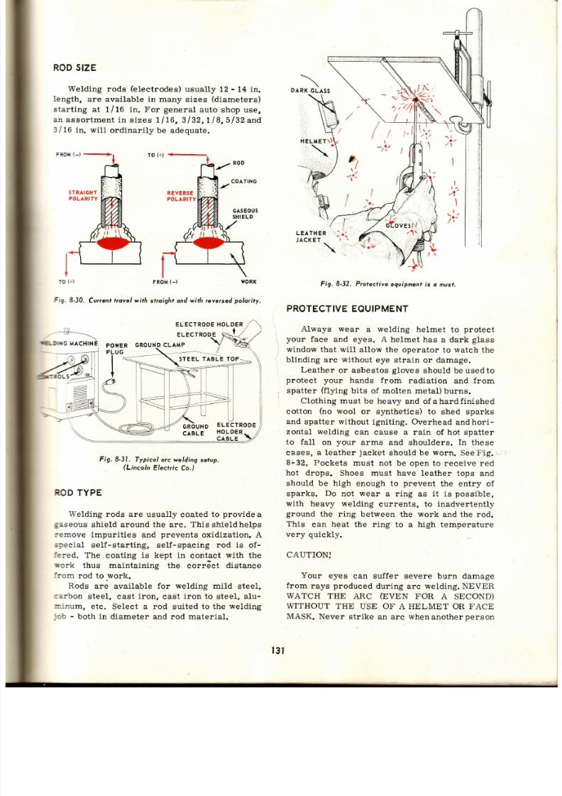
7/26/2019 Auto Service and Repair - Martin W. Stockel
http://slidepdf.com/reader/full/auto-service-and-repair-martin-w-stockel 131/224
ROD
SIZE
Welding rods
(electrodes)
usually
t2
-
L4 in.
length,
are available in many
sizes
(diameters)
starting
at
1/16
in. For
general
auto shop use,
an
assortment
in s izes
1lt6,3l32,Ll8,5l32and
3/16
in.
wi l l
ord inar i lybe
adequate.
TO
(+ )
I
t
TO
(+)
FR9M
_)
WORK
Cu¡renl
trovel with
straight and with reye¡sed
polority,
ie.
8-30.
HOLDER
--
rl-=- I
DARK
GLA55
STEEL
TABLE TOP
ELECTRODE
HOLDER
CA
Fig. 8-31.
Typicol arc welding
setup,
(Lincoln
Elec¡r ic
Co.)
ROD
YPE
Welding
rods are usually
coated
to
provide
a
gaseous
shield around the arc. Th isshieldhelps
:emove
impurities
and
prevents
oxidization. A
special self-starting, self-spacing rod is of -
fered.
The
coating
is kept
in contact
with
the
Tork
thus maintaining
the corráct
distance
irom
rod to.work.
Rods
are available
for welding mild
steel,
carbon
steel, cast
iron,
cast
iron
to steel,
alu-
*inurr l,
etc. Select a rod
suited
to the welding
ob
-
both in
diameter and rod
material.
POWER
PLUG
--_.-,_
1-,
I , ' , .
I
LEATHER
JACKET
Fig. 8-32. Profective
equipment s o musf,
PROTECTIVE
EQUIPMENT
Always wear
a welding helmet
to
protect
your
face
and eyes. A
helmet has a dark
glass
window
that wil l al low
the operator
to
watch
the
blinding arc without
eye strain
or
damage.
Leather
or asbestos
gloves
should beusedto
protect
your
hands
from radiation
and
from
spatter
(flying
bits of molten metal)
burns.
Clothing
must be heavy
and of ahardfinished
cotton
(no
wool
or synthetics)
to shed sparks
and
spatter
without
igniting. Overhead
andhori-
zontal welding
can
cause
a rain
of hot spatter
to
fal l
on
your
arms and
shoulders.
In
these
cases, a leather
jacket
should be
worn.
See
Fig.
8¡ .32. Pockets
must
not be
open to receive red
hot drops.
Shoes must have leather
tops and
should
be high
enough to
prevent
the entry
of
sparks.
Do
not
ri lear
a r ing
as
i t
is
possible,
with
heavy welding
currents, to
inadvertently
ground
the
ring between
the
work
and the rod.
This
can
heat
the r ing to
a
high
temperature
very
quickly.
CAUTION,I
Your
eyes
can suffer severe
burn damage
from
rays
produced
during
arc
welding. NEVER
WATCH THE
An,C
(PVEM
FOR A
SECOND)
WITHOUT THE
USE OF'A HELMET OR FACE
MASK.
Never
str ike
an
arc when
another
person
I
\
IIIIELDIII{G
ACHINE
H
ELMET\I
STRAIGHT
POLARITY
ELECTRODE
ELECTRODE
GROUND LAMP
f3t
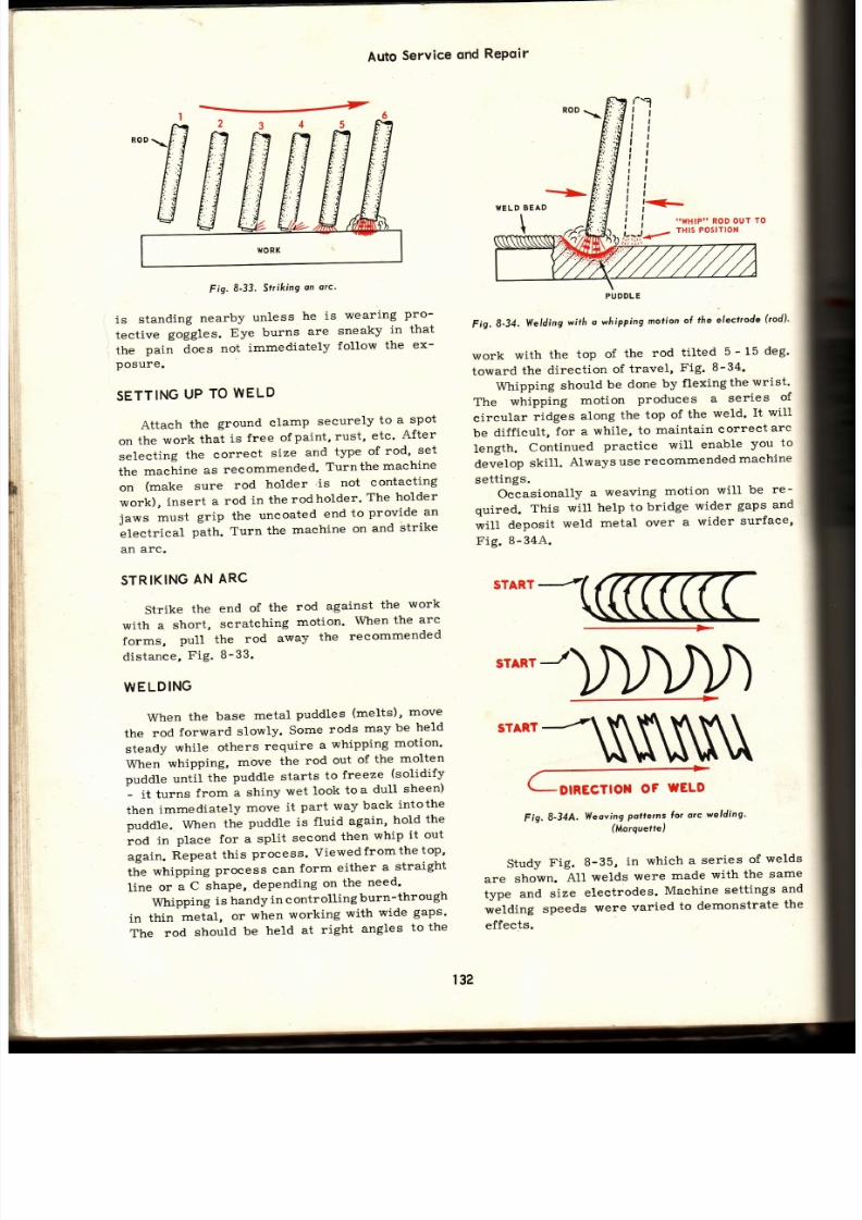
7/26/2019 Auto Service and Repair - Martin W. Stockel
http://slidepdf.com/reader/full/auto-service-and-repair-martin-w-stockel 132/224
Auto
Service
ond
RePoir
Fig.8 '33'
Str ik ing
an
orc'
is
standing
nearby
unless
he
is
wearing
pro-
tective
gojgfes.
Eye
burns
are
sneaky
in that
the
pain does
not
immediately
follow
the
ex-
posure.
SETT¡NG
P
TO
WELD
Attach
the
ground
clamp
securely
to
a
spot
on
the
work
that
is
free
ofpaint,
rust,
etc'
After
selecting
the
correcl
size
and
t¡pe
of
rod'
set
the
machine
as
recommended.
Turnthe
rnachine
on
(make
sure
rod
holder
'is
not
contacting
work),
insert
a
rod
in the
rodholder'
The
holder
jaws
must
grip the
uncoated
end
to
provide
an
Llectrical
path.
Turn
the
machine
on
and
3trike
an
arc.
STRIKING
AN
ARC
Fig,
8-34.
Welding
with
o whipping
motion
o( ¡he
elect¡ode
(rod)'
work
with
the
top
of
the
rod
tilted
5
-
15
deg'
toward
the
direct ion
of
travel,
Fig.
8-34'
Whipping
should
be
done
by
flexing
the
wrist'
The whipping
motion
produces
a
series
of
circular
ridges
along
the
top
of
the
weld' It wil l
be
difficult,
for a
while,
to
maintain
correct
arc
Length.
Continued
practice
will
enable
you
to
develop
skil l .
Always
use
recommended
machine
sett ings.
Occasionally
a
weaving
motion
will
be
re -
quired.
This
wil l
help
to
bridge
wider
gaps
an d
*i11
d.posit
weld
metal
over
a
wider
surfaee'
Fig.
8-34,4..
Strike the
with
a
short,
forms,
Pull
distance,
Fig.
WELDING
end of the rod against the
work
scratehing
motion.
When
the
arc
the
rod
awaY
the
recommended
B-
33.
START
srARr-D
srARr-N
/ -
r-g¡¡¿gTto¡
oF
WELD
Fig. 8-34tA. WeovingPottetns Íor orc welding'
(Mo¡guefre)
Study
Fig.
8-35,
in
which
a series
of
welds
are
shown.
AI1
welds
were
made
with
the
same
type
and
size
electrodes.
Machine
sett ings
an d
*áfai g
speeds
were
varied
to
demonstrate
the
effects.
When
the
base
metal
puddles
(melts) '
move
the
rod
forward
slowly.
Some
rods
may
be
held
steady
while
others
require
a
whipping
motion'
When
whipping,
move
the
rod
out
of
the
molten
puddle
,rtttii
ttt.
puddle
starts
to
freeze
(solidify
-
it trtrr
from
a shiny
wet
look
toa
dutl
sheen)
then immediately
move
it
part
way
back
intothe
puddle.
When
the
puddle
is
fluid
again' hold the
rod
ln
place
for
a split
second
then
whip
it
out
again.
Repeat
this
process.
Viewedfromthe
top'
the
whipping
process
can
form
either
a
straight
line
or
.
C
tt pu,
depending
on
the
need'
Whipping
is
handy
in c
ontrolling
burn-through
in
thin
metal,
or
when
working
with
wide
gaps'
The
rod
should
be
held
at
right
angles
to
the
|
wxre
RoD ur
ro
;
-
TH|S POSITION
PUDDLE
132

7/26/2019 Auto Service and Repair - Martin W. Stockel
http://slidepdf.com/reader/full/auto-service-and-repair-martin-w-stockel 133/224
Solder ing,
Brozing,
Welding,
Crqck
Repoir
, \ .
A
good,
smooth weld. Note
the even
whip
marks
and
lack
of spatter.
B.
Machine
settings too low.
The
wetd is
narrow
with
l i t t le
penetration.
I t
is
piled
high.
C. Machine
settings
too
high.
Note
excessive
width, blowholes and heavy spatter.
D.
Sett ings
O.K. but
arc too
short.
E.
Settings O. K. but
arc too 1ong.
F.
Sett ing
O.
K.,
arc
O. K.
but speed too s low.
G.
Arc O.
K.,
sett ings
O.
K.
but speed too fast.
tr¡g.
8-35.
fhe ef fects ol vorious
mochine
seffings,
orc Iengths
ond
welding
speeds.
Rod
rype ond
size
remoined
constont.
(Lincoln
E/ectr ic
Co.)
The
sound of the arc
is
helpful
in
determining
-¡hen
i t is the
correct length and of the
proper
:-eat,
A
good
arc
has
a steady
bacon
frying 1n
:ie pan
sound.
A short
arc
wil l make
popping
---o ises
and wi l l tend to
cause
the rod to
st ick
to
:re
work. Excessive
arc length
wi l l
cause a
:--gh,
humming
noise with
a lot
of
spatter.
Th e
=r'c
also tends to
go
out.
MANY
YPES
OF WELDS
Weld
posi t ion
and
work
set-up can be
quite
'.-aried. This
wil l requíre
ski1l
inflat,
horizontal,
' -er t ieal
and overhead welding.
See
Fig.
B-36.
WORK
SHOULDBE CLEAN
Despite the fact that
a
good
welder
ean
ru n
=
bead.through
rust,
pai .nt,
moisture, etc ., a l l
neld
areas
should
be dry and
clean.
The weld
arl l
go
faster, look better
and
wil l. be
stronger.
Chip the
slag
(brittle
eoating
left
on
the weld
from
the
rod
coating
mater ia l)
from
the bead
and use
a
wire
brush tocompletethecleanup
job
before
making
the next
pass
(bead).
Some thick
parts
require
a number
of
passes.
I f the s lag is
not removed
the
joint
may
be full of slag inclu-
s ions
{par t ic les)
and blowholes
(air
pockets) .
WHEN
CHIPPING OR
WIRE BRUSHING,
WEAR
PROTECTIVE
GOGGLES UNLESS YOUR
HELMET
IS DESIGNED TO TlP
UP THE DARK
GLASS AND PERMIT YOU TO
LOOKTHROUGH
THE
CLEAR
GLASS. GETTING A PIECE OF
SLAG IN YOUR EYE
CAN BE EXCEEDINGLY
SERIOUS.
BASIC
SAFETY RULES
FOR
ARC
WELDING
1.
Never
look at
the arc unless wear ing
a
suitable helmet
or face shield.
2. Do
not
permit
bystanders,
unless they
ar e
wear ing protect ive gear.
3.
Wear
goggles
when
chipping or
wire
brush-
ing.
4.
Wear
protect ive
c lothing and
gloves.
5. Make
certa in the welding machine
is
proper-
l r r c ¡n -AoA
6.
Never weld whi le
standins in water
or on
. . t^*^
^-^,,-á
7. Never
careless ly s tr ike an
arc on a cargas
tank, or on
eompressed
gas
cyl inders.
B. Do
not s tr ike arc on automobi lebrakel ines-
gas
l ines,
etc .
9. Have
adequate
venti lation.
10.
Be
careful
when weldingmetalwi thcoatings
such
as z inc,
cadmium,
bery l l ium,
etc,
The
fumes
may be
deadly.
11. Disconneet
the welding machine before
attempting
any
repairs .
HORIZONTAL
EDGE WELD
DOUBLE
BUTT
WELD
BUTT
WELD
t33
Fig. 8-36.
Di lh¡ent
we/ds ond welding
posi l ions.
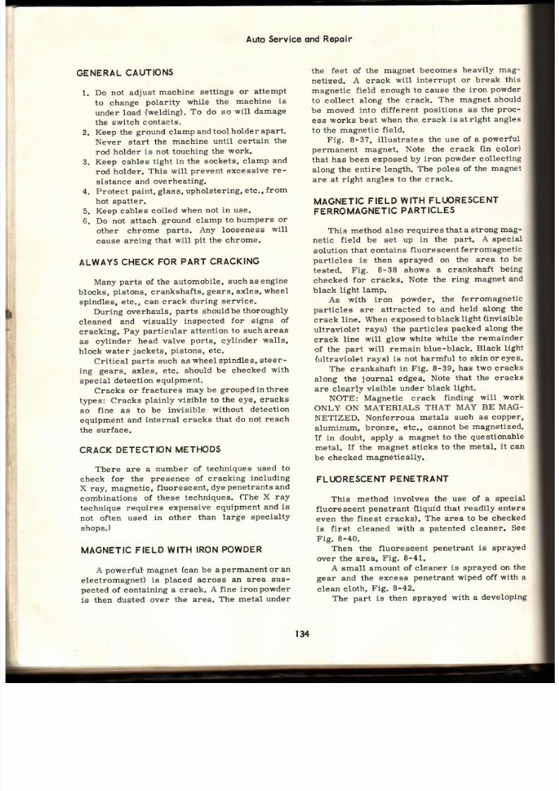
7/26/2019 Auto Service and Repair - Martin W. Stockel
http://slidepdf.com/reader/full/auto-service-and-repair-martin-w-stockel 134/224
GENERAL
AUTIONS
1.
Do not adjust
machine
settings
or attempt
to change
polarity
while the
machine
is
under
load
(wetding).
To do
so
will damage
the switch
contacts.
2.
Keep the
ground
clampandtoolholderapart.
Never start
the
machine
until
certain
the
rod
holder
is not
touching
the
work.
3.
Keep cables
tight
in the
sockets,
clamp
an d
rod
holder.
This will
prevent excessive
re-
sistance
and
overheating.
4.
Protect
paint, glass, upholstering,
etc.,
from
hot spatter.
5.
Keep
cables
coiled
when not
in
use.
6. Do not
attach
ground
clamp
to
bumpers
or
other
chrome
parts. Any looseness
will
cause
arcing
that
will
pit
the chrome.
ALWAYS
HECK
OR
PARTCRACKING
Many
parts
of
the automobile,
suchasengine
blocks,
pistons,
crankshaftsr
g€4rs,
axles,
wheel
spindles,
etc.,
can
crack
during service.
During overhauls,
parts
shouldbe
thoroughly
cleaned
and visually
inspected
for signs
of
cracking.
Pay
particular attention
to suchareas
as cylinder
head valve
ports,
cylinder
walls,
block
water
jackets,
Pistons,
etc.
Critical
parts
such as
wheel spindles,
steer-
ing
gears,
axles,
etc.
should
be
checked
with
special
detection
equiPment.
Cracks
or
fractures
may be groupedinthree
types: Cracks
plainly
visible
to the
eye,
cracks
so fine
as
to
be
invisible
without deteetion
equípment
and
internal cracks
that
do
not
reach
the
surface.
CRACK
DETECTION
ETHODS
There
are
a
number
of techniques
used
to
check
for the
presence of cracking
ineluding
X
ray,
magnetic,
f l uorescent,
dye
p,enetrants and
combinations
of
these
techniques.
(The
X
ra y
technique
requires
expensive
equipment
and
is
not often used ín other than large speeialty
shops.)
MAGNETIC
IELDWITH
RON
OWDER
A
powerful magnet
(can
be a
permanent
or
an
electromagnet)
is
placed
across
an area
sus-
peeted
of eontaining
a
craek.
A fine
ironpowder
is
then dusted
over
the area.
The
metal
under
the
feet of the
magnet
becomes
heavily
mag-
netized.
A crack
will interrupt
or break
this
magnetic
field
enough
to
cause
the
iron
powder
to
collect
along
the crack.
The magnet should
be
moved
into
different
positions as the
proc-
ess
works
best
when the crack
is at right
angles
to the magnetic field.
Fig. 8-3?,
il lustrates
the
use of
a
powerful
permanent magnet.
Note the crack
(in
eolor)
that has
been exposed
by
iron
powder
collecting
along
the
entire length.
The
poles
of the
magnet
are at
right
angles
to the crack.
MAGNETIC
IELD
WITH
FLIJORESCENT
FERRO
AGNET
C
PARTCLES
This
method also
requires
that
a strong
mag-
netic
field be set
up
in the
part.
A special
soLution
that contains
fluorescent
ferromagnetic
particles is then sprayed on the area to be
tested.
Fig. 8-38 shows
a crankshaft
being
checked
for
cracks.
Note the
ring
magnet and
black light
lamp.
As
with iron
powder, the
ferromagnetic
particles
are attracted
to and
held along
th e
crack
line.
When
exposed
oblack
light
(invisible
ultraviolet
rays)
the
particles
packed
along
th e
craek
line
will
glow white while
the
remainder
of
the
part will remain
blue-black.
Black
light
(ultraviolet
rays)
is not
harmful
to skinoreyes.
The
erankshaft
in
Fig. 8-39,
has two cracks
along
the
journal
edges.
Note
that the cracks
are cleprly visible under black light.
NOTE: Magnetic
crack
finding
will
work
ONLY ON
MATERIALS
THAT
MAY
BE
MAG-
NETIZED.
Nonferrous
metals such
as copper,
aluminum,
bronze,
etc., cannot
be
magnetized.
If in doubt,
apply
a
magnet
to the
questionable
metal.
If the
magnet sticks
to
the
metal,
it
can
be
checked
magnetically.
FLIJORESCE
NT
PE
NE
TRANT
This
method
involves the
use
of a special
fluorescent
penetrant
0iquid
that
readily enters
even the finest cracks). The area to be checked
is
first
cleaned
with a
patented
cleaner.
See
Fig. 8-40.
Then
the
fluorescent
penetrant is sprayed
over
the area,
Fig.
8-41.
A
small
amount
of
cleaner
is sprayed
on
th e
gear
and the
excess
penetrant
wiped off
with a
clean
cloth,
Fig.
8-42.
The
part is then
sprayed
with a
developing
Auto
Service
qnd
Repoir
134

7/26/2019 Auto Service and Repair - Martin W. Stockel
http://slidepdf.com/reader/full/auto-service-and-repair-martin-w-stockel 135/224
IRON
OWDER
OWERFUL
CRACK
DUSTER
PERMANENT
MAGN
T
Fig.8-37.
Crock
in
cyl inder
ñeod
is exposed
through
he
use ol
a
powerlul
mognet
ond
iron
powder.
(Storm-yulcon¡
Fig.8-40.
Cleaning
section
of large geor
i l iot
to
oppl icotion
ol
lluo¡escent
penelron ,
Fig.8-38.
Checking
cronksho{t
or
uocks.
Fíg-8-39.
Crocks n cronkshoft
reploinly
visihle
under
block
l ight.
(Mosnollux)
solution.
The
developer
wil l
draw
the
penetrant
:o
the
surface
of the
cracks,
i f
any, Fig.
B-43.
The gear
is
ex4mined
under
a
lamp
that
e:nits
black
l ight. I f
any
cracks
are
present,
the
developed
penetrant
wil l glow
quite
visibly,
Frg.
B-44.
Fig. 8-41. Applying luorescent penetrcnt.
(Mo9no(lux)
Fig.
8-42,
Removing
excess penetront.
Fig. 8-43.
Applying
deve/oper
olufion.
i
f
i
/'::
135
Fig.8-44.
Examining
he port
under block
Iight.
Note l ¡e
c¡ock.
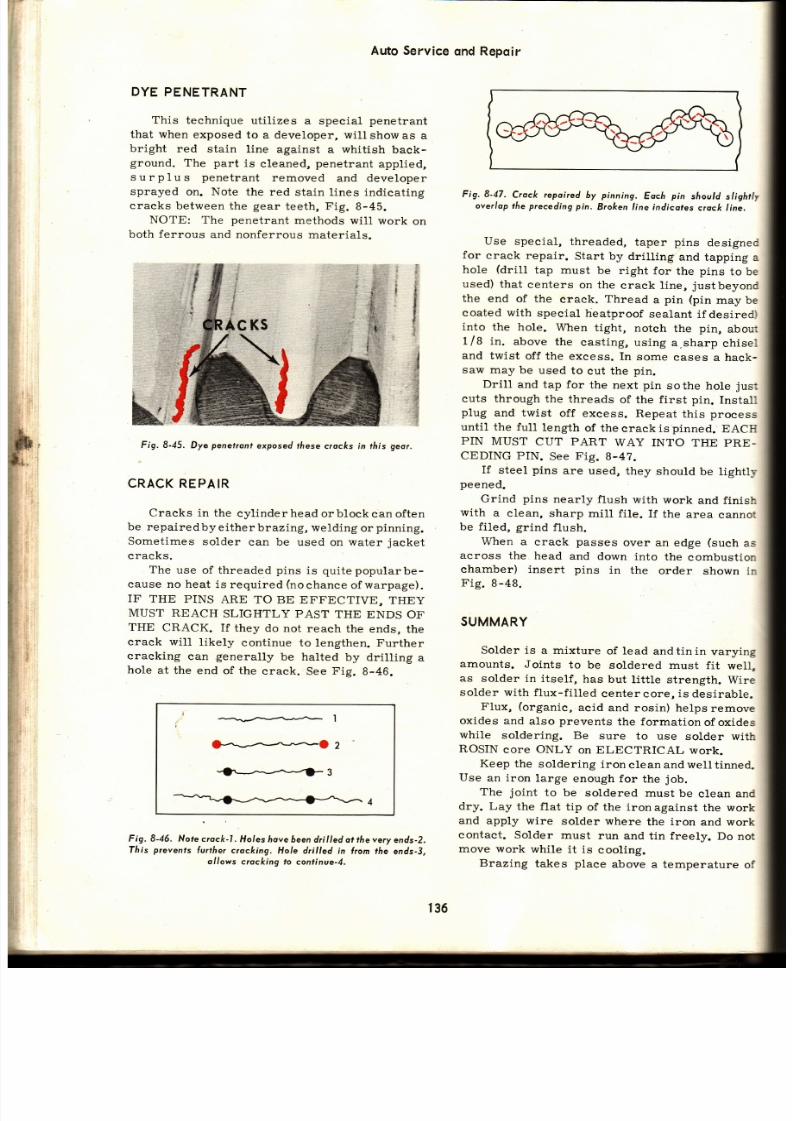
7/26/2019 Auto Service and Repair - Martin W. Stockel
http://slidepdf.com/reader/full/auto-service-and-repair-martin-w-stockel 136/224
Auto Service
ond Repoir
DYE
PENETRANT
This
technique
ut i l izes
a specia l
penetrant
that when
exposed
to a developer,
wi l l
show as
a
bright
red
stain
line against
a
whit ish
back-
ground,
The
part
is
cleaned,
penetrant
applied,
surp lus
penetrant
removed
and developer
sprayed on. Note the red stain lines indicating
craeks
between
the
gear
teeth,
Fig.
B-45.
NOTE:
The
penetrant
methods wiI I
work
on
both
ferrous
and nonferrous
materials.
'i
j
{
¡(c
s
,j
.¡*
€
,a-::i
'l é
.s
.
i"$
,+
{
Fig. 8-45.
Dya
penetron
exposed
these crocks
in th is
Qeor ,
CRACKREPAIR
Cracks in
the
cyl inder head
orblock
ean often
be repaire
d by e the r
br azing, we ding
or
pinning.
Somet imes
solder
can be
used on
water
jacket
cracks.
The
use of threaded
pins
is quitepopularbe-
cause no heat
is required
(nochance
ofwarpage).
IF THE
PINS
ARE TO
BE EFFECTIVE,
THEY
MUST
REACH
SLIGHTLY PAST
THE ENDS
OF
THE
CRACK. I f
they
do not
reach
the ends,
the
craek will
l ikely
continue to
lengthen. Further
cracking
can
generally
be halted
by dril l ing
a
hole at
the
end of the
crack.
See
Fig.
8-46.
Fig. 8-46.
Note c¡ock-1.
Holes hove
óeen dr i l ledot thevery
ends-2.
Tlr is
prevenfs
lur the¡
crocking.
Hole dr i l led in l ¡om
the
ends-3,
ol lows c¡ocking to
conl inue-4.
Fig.8-47.
Crock repoired
by
pinning.
Eoch
pin
should
sl ight ly
over lop
he
preceding
pin.
Broken ine indicotes
crock I ine.
Use
specÍa l,
threaded,
taper
pins
designei
for
crack repair.
Start by
dril l ing
and tapping
a
hole
(dr i l l
tap must
be
right
for
the
pins
to be
used)
that
centers
on the
crack
l ine,
justbeyonc
the
end of the
erack.
Thread
a
pin
(pin
may be
coated
with
specia l
heatproof
sealant
i fdesired,
into
the hoLe.
When
tight,
noteh
the
pin,
abou:
1/8 in .
above
the
cast ing, using
a.sharp
chise-
and
twist
off the
excess. In
some
cases
a hack-
saw may be used to cut the pin.
Dril l
and tap for
the next
pin
sothe hole
jus:
cuts through
the
threads
of the f irst pin.
Install
p lug
and twist
off
excess. Repeat
th is
process
until the fu11
length
of the
crack
is
pinned.
EACIi
PiN
MUST
CUT
PART
WAY INTO
THE
PRE-
CEDING PIN.
See
Fig.
B-4?.
If
steel
pins
are
used,
they
should
be lightl¡
peened.
Grind
pins
nearly f lush
with work
and f inisl:
with
a
clean, sharp
mi11 f i le.
If
the
area
canno:
be f i led, grind
flush.
When a
crack
passes
over
an edge
(such
as
across the head and down into the combustior_
chamber) insert pins
in the
order
shown
ir
Fig.
B-48.
SUMMARY
Solder is
a mixture
of lead
andt in in
varying
amounts. Joints
to
be
soldered must
f it
well,
as solder in
itself,
has
but
lit t le strength.
Wire
solder with
f lux-f i l led
center core, is desirable.
Flux,
(organic,
acid
and rosin)
helps
remove
oxides
and
also
prevents
the formationofoxides
while
soldering.
Be
sure
to
use solder
wit l:
ROSIN core ONLY on ELECTRICAL work.
Keep
the
solder ing
ironclean
andwell t inned.
Use
an iron
large
enough
for
the
job.
The
joint
to
be
soldered must
be
clean
an C
dry. Lay
the
flat
t ip of the iron
against
the
work
and apply
wire
solder
where
the
iron
and work
contact.
Solder
must
run
and t in freely.
Do
no t
move work
while
i t
i.s
cooling.
Brazing
takes
place
above
a temperature
of
136

7/26/2019 Auto Service and Repair - Martin W. Stockel
http://slidepdf.com/reader/full/auto-service-and-repair-martin-w-stockel 137/224
Solder ing,Brozing,
300
deg.
F. The work
must be
clean.
Flux work,
a¡d heat
unti l
brazing rod wil l melt
when in
eontact with the
parts.
Capil lary
act ion
will
Craw
the
brazing
material into
the
joints.
Donot
ryverheat.
Braze
welding requires t inning the
work with
braze
material
and
then building up to
f i l l
joint
:rregularit ies,
and
to
provide
strength.
Bronze
brazing rod may be used on
cast
:ron,
malleable iron and steel.
Either
a
propane
or an oxyacetylene
torch
:ray
be
used.
Fig.8-48. nserl
pins
n theo¡de¡
hown.
in 6 wil l lock
pin
5 in
place
n
cose
pin
7
does
ot
properly
verlap.
Choose a torch
t ip appropriate
for
the
work.
Set the gas pressures as recommended by the
torch manufacturer .
Use a neutral
f lame
approximately
one-to-one
mixture of
acetylene
and oxygen) to slight ly
carburizing
f lame
one-
to-one
mixture is varied
to
give
excess of
acetylene).
Hold the t ip at an angle
to
the
work.
Vary
the distance
from
tip
to
work
as
needed.
Keep t ip in
motion to avoid localized
overheating.
Gas
welding involves
fusion
melt ing
an d
mixing) of the
metals to
be
joined.
The
work
should
be
clean
and
dry.
Thick metals shouldbe
beveled.
Select
a
torch t ip of
the size
recom-
mended by the
manufacturer. Set
gas pressures
for selected tip. Adjust to a neutral f lame.
When
welding, keep the
inner
f lame
from
touching
either
f i l ler rod or
puddle. Bring
th e
work
to
the molten
state and,
if required,
ad d
fi l ler rod.
The weld
must
penetrate the
work
and should
be
solid
añd
free of
slag and
blow-
holes.
Cutt ing
is
fast
and
easy
with oxyacetylene
cutt ing
torch.
Welding,Crqck
Repoir
Foll.ow
all safety
precautions
in
sett ing
up
equipment,
l ight ing torch and in
welding.
Arc
welding is
fast
and applies a minimum
amount
of
heat
to
the work. Although
the arc
temperature is high, the welding
process
is
so
rapid that the
work
remains relat ively
coo1.
This
helps
control
warpage.
Select appropriate
rod size and t1pe.
Adjust
machine to correct
polarity
and
cur-
rent sett ings.
Tip
the
top
of the rod in the
direct ion of t ravel
5
-
15
deg.) . A whipping
motion
will help
control the
heat,
direct ion and
penetrat ion
of
the
weld.
The
bead should be smooth, even,
with
good
penetrat ion
and should
be free
of slag andblow-
holes. Remove
slag
from
a
bead before welding
another
pass
over the original bead.
Follow
all safety rules
in
sett ing up and
operat ing.
Cracks
can
be detected by using a
magnetic
technique involving iron powder or f luorescent
liquid,
or,
by
using either
dye
or
f luorescent
penetrants.
Cracks
in
engine
blocks and heads
can
often
be repaired by
pinning.
Use tapered, threaded
pins. Pins
should overlap slight ly
and must run
full length
of the crack.
MANY
SKILLS ARE REOUIRED
The top-leve1 mechanic,
capable of
handling
the
many
phases
of automotive repair,
must
have a number of talents.
Numerousbasic skil ls
are required, not all. of which are commonly
associated with auto work.
Being
a successful
mechanic involves
much
more than
mere disassembly,
inspection,
part
replacement and
reassembly.
Quite
often
parts
must be
rebuilt , altered,
adapted, welded, etc.
To
cope
successfully
with
allthese
demands upon
his skil ls, the
mechanie must have some knowl-
edge of machine shop,
welding andbrazing, sheet
metal work,
electr icity,
etc.
When
you, in your work
as a
mechanic, meet
a situat ion that calls
for skil ls
you
do
no t
possess,
DEVELOP THEM. Night sehool, ex-
tension courses, on the job training, books,
manuals, trade
journals
and magazines, allpro-
vide
opportunit ies
for
you
to learn.
Remember that each
year
sees
changes
in
design, the
introduction ofnew units, new service
techniques, service equipment
and
materials.
Be
sure to develop a
regular
program
of
read-
ing and study, so
you
are always
UP-TO-DATE.
It wil l
pay
big dividends.
137
;¡i
ii
ii
iir
il i
ii
lll
ii
i:
ti
rli
ilI
ii
ir
iii
ln
li
ri
niz.B/tÁ
7/26/2019 Auto Service and Repair - Martin W. Stockel
http://slidepdf.com/reader/full/auto-service-and-repair-martin-w-stockel 138/224
1. Soldering
involves
fusion.
True
or
False?
2.
Joints
should
be
wellfi ttedbefore
soldering.
True or
Fa1se?
3. Solder
is a
mixture
of-and-.
4. Commonly used solder alloys are 40/60,
^-^
5.
Flux
is used
in soldering
to:-
a.
Clean
the
metal.
b.
Prevent
overheating
of
metal.
c.
Cement
Parts
together
d.
Prevent
rusting.
6.
Three
kinds
of
flux are:
7.
-f lux
should
be
used
on
all
electrical
work.
B.
The tip
of
the
iron should
be
well-.
9.
When applying
solder,
touch
the
wire:
a. To toP of iron.
b.
To
work away
from
iron.
c.
To
iron
where
it contacts
work.
d.
To
side
of
iron.
10.
Brazing
involves
temperatures
above:
a. 1800
F.
b.
450
F.
c.
800
F.
d.
3000
F.
11.
Brazing
and
braze
welding
are
one
and the
.same.
True or
False ?
12.
F lux is
requi red
forbrazing.
True
orFalse?
13.
When using
an oxyacetylene
torch
for braz-
ing, the
flame should
be-to
slightly
14.
The torch
tip
shouLd
be
held at
right
angles
to
give
better
penetration
whenbrazing.
True
or
False
?
15.
For
brazíng,
tip size
and
gas
pressures
ar e
not too
imPortant.
True
or
False
?
16.
Brazing
requires
that
the
parent metal
be
brought
to the
fusion
point.
True or
False?
1?.
The flame
for
welding
should
be--.
18.
The inner
flame cone-
-touch
the
weld
puddle
or
rod
tiP.
19.
Add fi l ler
metal
to
the
weld
bY :
a.
Touching
rod to
Puddle.
b.
Holding
rod above
puddle and allowing it
to
driP
in.
c.
Laying a
length
of
rod
flat on
the
joint.
d.
Melting
and
depositing
drops
of rod
al l
along
the
joint
before
puddling
the
base
metal.
Auto
Service
qnd
RePq¡r
OUIZ
-
ChcPter
8
20.
The
cutt ing
torch
uses
a
jet
of-to
pro-
duce
the cutting
action.
21.
Hold
the cutting
torch
at
a sharp
angle
to
the
work.
True
or
False?
22. Acetylene tanks should be used in a-
posit ion.
23.
The oxygen
regulator
has a
thread.
24.
Open
tank valves
25. A lways
wear- ,-
and-_
when
welding,
brazing
or cutting.
26.
Before
opening
tank valves,
regulator
han-
dles
should
be :
a.
Removed.
b.
Backed out
unti l
free.
c.
Tightened
securelY.
d.
Baeked
half
waY out.
2?. Oi l and
grease
should
be
keptawayfromgas
welding
equiPment.
True or
False
?
28.
Before
lighting
the
torch,-bothlines.
29.
The aeetylene
tank
should
be opened:
a.
All
the
waY.
b.
Four
turns.
c.
One turn.
d. 1/16
turn.
30.
Some
coatings
wil l
give
off
poisonous
fumes
when
heated.
True
or
False?
31.
Never use
acety lene
pressures
in
excess
of
-
psi .
32.
Arc
welders
can
be either-or
or
a
combination
of
both.
33. Arc
welding imparts less heat to the work
(overall)
than
gas
welding.
True
or
False?
34.
List
f ive
welding
electrode
sizes
suitable
for
garage
use.
35.
Welding
rods
are
usually
coated.
True or
False
?
36.
Watching
the
arc
without
protective
equip-
ment can
cause
serious
eye
damage.
True
or
False
?
3?.
Rod-and-must
be
in
keePing
with the
job.
38.
The
hotterthe
arc,
thebetter.
True or
False?
39.
Deseribe
the
sound
of
a
proper arc.
40. Never weld, braze or solder fuel tanks until
special
precautions
have
been
taken.
True
or
False?
41.
Describe
four
methods
of craik
detection.
42.
Cracks
can
often
be
repaired
without
heat
t38

7/26/2019 Auto Service and Repair - Martin W. Stockel
http://slidepdf.com/reader/full/auto-service-and-repair-martin-w-stockel 139/224
Chapfer
9
CLEANING
QUIPMENT
ANDTECHNIQUES
Cleaning
parts,
on
the car
or off,
can
be a
slow, tedious
job
unless
the
proper equipment
is
available and
is usedcorrectly.
Onmany
jobs,
the
cleaning
portion, using
the best
equipment,
can account
for nearly
one
-half
the
time
involved.
To
use even
more
t ime
because of
poor
equip-
ment and techniques wil l run the repaircharges
up
to the
point where the
sbop
wil l be
hard
pressed
to offer competitive
repair
price
sched-
ules.
Time is l ike money
-
it must
not be
wasted.
BE
THOROUGH
On
an
in-car engine
clean,
or an
under-body
clean
j
ob,
leaving
a
few
ttholidays
(missed
spots)
wil l displease
the customer,
but
mechanieally
¡nill
not
prove
disastrous.
On
the other
hand,
eareless
cleaning
of
parts
during
engine,
trans-
miss ion,
rear end,
etc .,
teardowns,
may
ruin
:he
job,
and cause
expensive
combacks
andpoor
customer
relations.
Fig.9-1.
Removing
com6uslion
chamber
deposifs
with
o
rolory
wi¡e
wheel.
(Albettson
& Co.)
The only safe course
is to be absolutely
meticulous
in
your
cleaning.
Remove
AL L
foreign materials
from the
part
and
protect
against
contamination
during subsequent
storage
and
handling.
NUMEROUSYPES
'
The equipment
and techniques
vary
with
th e
size
and type of
job
involved.
You
are
obviously
not
going
to f i re up a s teamcleanerto
c lean
on e
universal
joint
when
solvent,
brush
and airhose
will
handle the task
quickly.
On
the other
hand,
to
attempt
to
clean
the
outside
of an engine
prior to disassembly,
with a brush
and solvent,
would be equatly
foolish.
You
must
tailor
the
equipment
and solution
to the
job
at
hand.
This
chapter
wil l deal
with the
widely
used
techniques. Study
them carefully
so
you wil l be
able
to
choose
wisely.
CLEANING
ITH
WIRE
BRUSH
NDSCRAPER
Valves, combustion
chambers,
piston
heads.
and
grooves,
etc.,
are subject
to
accurnulations
of hard carbon.
If they are
not soakedin
power-
ful
cleaners,
they
must
be cleanedwith
scrapers
and
power brushes.
The
heavy deposits
can
be knocked
off
with
scraping tools
and a
power
wire wheel, or,
a
dri l l-driven
rotary
brush
may be used
for
final
cleaning.
Clean dry. After thorough carbon removal,
the
part
should
be
washed in solvent
and
blown
dry.
NEVER USE
A
POWER
BRUSH
ON
SOFT
ARTICLES
SUCH
AS
PISTONS, CARBURE
TORS,
BEARING
INSERTS,
ETC.
Fig. 9-1 shows
car:bon
deposits
in a cylinder
head combustion
chamber
béing
removed
with a
rotarywirebrush
chucked
in
an air-operated
dril l .
139

7/26/2019 Auto Service and Repair - Martin W. Stockel
http://slidepdf.com/reader/full/auto-service-and-repair-martin-w-stockel 140/224
Auto
Service
ond
RePoir
GET
ADVICE
A
number
of companies
offer
various
types
of
cleaning
equipment
and
solutions
designed
to
perform
tasks
such
as car
body
washing,
in-car
Lngine
cleaning,
carburetor
cleaning,
block
cláning,
hard
carbon
removal,
etc'
There
ar e
hot solutions,
cold
solutions,
high-pressure an d
low-pressure
sprays,
agitators,
etc'
So
many
are
available
that
it can
cause
confusion
toany-
one
not
an
expert
in
the
field.
When
choosing
a
cleaning
solution
or
piece of
equipment'
it
is
wise
to
consult
other
shops
or
mechanics
for
their
reactions
and
also
to
discuss
the
problem
with
sales
representatives
from
reliable
com-
panies
offering
products
in
this
field'
SOLUTIONS
AN
BE
DANGEROUS
Many
cleaning
solut ions
are
TOXIC
(poison-
ous) and CAUSTIC (wii l burn skin, eyes)' Be
certain
you
know
WHAT
you are
using
and
follow
the
manufacturerst
recommended
handling
pro-
cedures.
General
safety
rules
concerning
cleaning
solut ions
are:
1.
Use
in
a
welL-venti lated
area'
2.
Never
use
gasoline
for cleaning'
3.
We.ar
goggles
or
face
shield
when
working
with
the
Powerful
tYPes.
4.
Keep
away
from
sparks
and
open
flame'
5.
Do
not
smoke
around
solutions'
6.
Keep
solut ions
coveredwhennot inuse'
Keep
in labeled containers.
Fig.
9-3.
Ploce
ports n bosket
nd
submerge
n
solvenf '
?. Use
solut ions
with
relat ively
high
flash
points
(temperature
at
which
vapors
will
ignite
when
brought
into contact
with
an
open
f lame).
B.
Never
heat
solut ions
unless
specif ically
recommended.
9.
Avoid
dampening
clothing
with solvent'
10.
Always
READ
and
FOLLOWmanufacturers'
instruct ions.
11.
When
brushing
parts
in sol'vent,
use
a
nylon
or
brass
brist le
brush
to
avoid
sparks'
12.
A
large
tank
of
solvent
should
have
a
lid
that
is
held open
by
a
fusible
link &olding
device
that
will melt
and
drop
the
lid
in
the
event
of
f ire).
13.
Wash
hands
and
arms
thoroughly
when
clean-
ing
job
is comPlete.
14.
Avoid prolonged skin exposure to aII types
of solvents.
PARTSWASHER
Although
small
parts can
be
cleaned
incans'
buckets,
etc.,
a
far
faster
and
more
efficient
job
can
be
accomplished
by
using
a
regular
cold
solution
Parts
washer.
The better
parts
washers
hold considerable
solvent,
have
soaking
trays,
solvent
agitation
and
a
filter
to
remove
impurities
from
the
solvent
for
rinsing.
Fig.
9-2,
i l lustrates
atypical
parts washer. They are available in many differ-
ent
s izes.
To use
the
parts
washer,
the
heaviest
de -
posits ean
be
quickly
removed
with
a
scraper'
On large
units
such
as
engines,
steam
clean
before
disassemblY.
The
parts are
placed
in
the
basket
and
sub-
merged
in the
solution.
Parts
with
hollow
areas
Sof€ry
Covcr
Porls
Cleoning
Bru¡h Rocl¡
Coñl'ol
Switó
Groyñillt
Pumping
Un¡l
I/25
HP-Abrosiv.
Proo.
Sook
Tonk
PLbl
G.ip
Fl h
Nozzlé
9-2.
Typical
cold
solut ion
porls wosher'
(GrcYmil ls)
Fis.
140

7/26/2019 Auto Service and Repair - Martin W. Stockel
http://slidepdf.com/reader/full/auto-service-and-repair-martin-w-stockel 141/224
:t
rl
should have
the hollows facing
up so that
an
ai r
trap
wil l
not
prevent.soLution
entry,
Fig.
9-3.
The
solution is then
agitated
(shaken)
by
ai r
pressure
or the
solution
passing,
under
pres-
sure, through
nozzles.
The
washer
shown
in
Fig.
9-4, has
a separate
compartment that
is
air
agitated while
the main
tank i.s used
fo r
soaking, brushing and r insing.
Fig.9-4. Po¡ts wosher wi lh
both oi r ogi tured ond sooking fonks.
(KIeer-Flo)
Fig. 9-5.
Mechonicinsing
ome
orts
whileotherswosh.
During
the agitation
cycle, some washers
have
a separate
basket
that wil l
hold a few of
the
parts
for
brushing
or
rinsing while the re-
mainder are sti l l . washing. Fig. 9-5, shows a
mechanic
brushing
and r insing a
few
parts
while
others
are soaking.
After
thorough
cleaning, the
parts
should
be
given
a final r inse. The machine
shown
in
Fig.
9-6,
has
both
a soft r inse and hard
spray
rinse.
The
mechanic
is
giving
the
parts
a final r inse.
The
solution from
both nozzles is fi l tered.
Fig.9-6, Giving
porls
o
l inol
¡ inse in l i l te¡ed
solvenf.
Solvent
musr be
CLEANI
Fol lowing
rinsing,
let
parts
draín
and
then
blow dry. I f there is a possibil i ty of rust
formation,
oil or
grease
the
part.
Keep
parts
covered unt i l ready
to use.
Some
garages
uti l ize
portable
parts
washers
that may
be wheeled
to the
job,
Fig.
9-?.
' 'HOT
TANK' 'CLEANING
Large
garages
or shops specializing in
re -
building,
usually have
a
hot
tank for heavy
Fig,9-7. Hondy
portoble
ports
wosher.
(KIeenFIo)
141
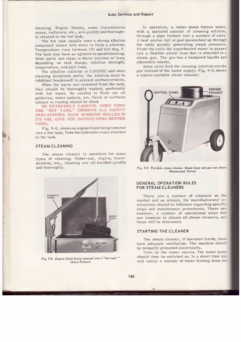
7/26/2019 Auto Service and Repair - Martin W. Stockel
http://slidepdf.com/reader/full/auto-service-and-repair-martin-w-stockel 142/224
Auto
Service ond
RePoir
cleaning.
Engine
blocks,
some
transmission
cases,
radiators,
etc. ,
are
quicklyandthorough-
ly
cleaned
in the
hot tank.
The hot
tank
usually
uses
a strong
alkaline
compound
mixed
with
water to
form a solution.
Temperature
runs
between
180
and
210
deg.
F.
The tank
may
have an
agitatortospeedcleaning.
Most
parts
are
clean
in
thi.rty
minutes
or less,
depending
on
tank
design,
solution
strength,
temperature,
and
Part
load.
The
alkaline
solution
is CAUSTIC
and
when
cleaning
aluminum
parts, the solution
must be
inhibited
(weakened)
to
prevent surface
erosion.
When
the
parts
are
removed
from
the
tank,
they
should
be thoroughly
washed,
preferably
with
hot
water.
Be
careful
to
f lush
out
oi l
ga l ler ies,
water
jackets,
etc.
Parts or
surfaces
subjeet
to rusting
should
be oiled.
BE EXTREMELY
CAREFUL
WHEN
USING
THE
I 'HOT
TANK. ' '
OBSERVE
ALL SAFETY
PRECAUTIONS.
HAVE SOMEONE SKILLED IN
ITS
USE, GIVE
YOU
INSTRUCTIONS
BEFORE
USING.
Fig.
9-8, shows
anengineblockbeing
lowered
into
a
hot tank.
Note the
hydraulic
crane
attached
to
the tank.
STEAMCLEANING
The steam cleaner
is excellent
for many
types
of cleaning.
Under-car,
engine,
trans-
mission,
etc.,
cleaning
are
a1l
handled
quickly
and
thoroughly.
Fig.9-8.
Engine
block
being
owered
into
o
hot
tonk.
(Sto¡n'Yulcon)
In operation,
a
water
pump forces water,
with a
metered amount of cleaning
solution,
through a
pipe
formed
into
a
number of coils.
A heat source
(o iL
orgas)passesheatup
through
the coils
quiekly
generating
steam
pressure.
From
the coils
the
superheated
water
is
passed
into a
flexible steam
hose that
is attached
to
a
steam gun. The gun has a heatproof handle anC
adjustable
nozzle.
Some
units
feed the cleaning
solutionintothe
gun
instead of
the water supply.
Fig. 9-9, shows
a typical
portable
steam cleaner.
Fig.
9-9,
Portoblesleom cleone¡. Steom
ose ond
gun
nol shown
(Homes¡eodYolve)
GENERAL
PERAT¡ON
ULES
FORSTEAM
CLEANERS
There
are
a
number
of cleaners
on
th e
market and
as
always,
the
manufacturersr
in-
structions
should
be
followed
regarding
specif ic
steps and
maintenance
proeedures.
There are
however,
a
number
of
operational
steps
tha:
are common
to alrnost
all
steam cleaners,
an c
these
wil l
be
discussed.
STARTING
THE CLEANER
The
steam
cleaner,
if operated
inside,
mus:
have
adequate
ventilation.
The machine shouli
be
properly
grounded
e1ectrically.
Turn
on
the
water source.
The water
pump
should
then be switched
on.
In
a short
t ime
yo';
will
notiee a
stream
of
water
fLowing
from the
142
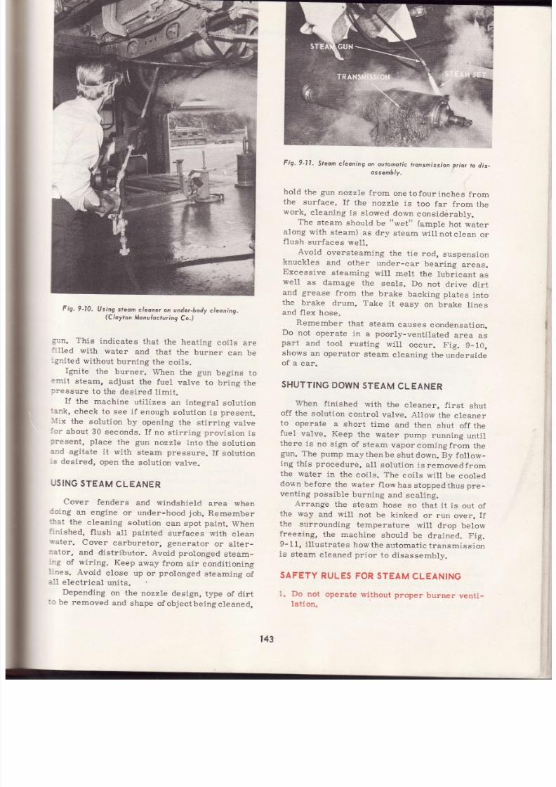
7/26/2019 Auto Service and Repair - Martin W. Stockel
http://slidepdf.com/reader/full/auto-service-and-repair-martin-w-stockel 143/224
Fig.9-10.
Using
feom
leoner
n
under-body
leaning.
(Clayton
Monuhcturing
o. )
gun.
This
indicates
that
the heating
coils
are
:: l led
with
water
and
that
the burner
can
be
:snited
without
burning
the
coils.
Ignite
the
burner.
When
the
gun
begins
to
?:rr it
steam,
adjust
the fuel
valve
to
bring
th e
¡ressure
to
the
desíred
limít.
If the machine uti l izes an integral solut ion
:.nk,
check to
see i f
enough
solut ion
is
present .
l I ix
the
solut ion
by
opening
the
st i¡r ing
valve
:cr
about
30
seconds.
If
no
st i r r ing provis ion
is
:resent,
place
the
gun
nozzle
into
the
solut ion
:-:rd
agitate
it
with
steam pressure.
If
solut ion
rs
desired,
open
the
solut ion
valve.
USING
TEAM
CLEANER
Cover
fenders
and windshi.el.d
area when
ioi.ng
an
engine
or under-hood
job.
Remember
:hat
the
cleaning
solut ion
can spot
paint.
When
i:r ished, f lush all painted surfaces with clean
;ater.
Cover
carburetor, generator
or alter-
:ator,
and distr ibutor.
Avoid prolonged
steam-
_:g
of wir ing.
Keep
away from
air
condit ioning
-:nes.
Avoid
close up
or
prolonged
steaming
of
: .11
lect r ical
uni ts .
Depending
on the
nozzle
design,
type
of dirt
:c
be
removed
and
shape
ofobjectbelngcleaned,
Fis.9-l
l .
Steom leonins
:. :r : ; ; : t .
r¡onsmission
rior
o
dis-
hold
the
gun
nozzle
from
one tofour
inches
from
the
surface.
I f
the
nozzle
is
too
far
from
the
work,
c leaning
is
s lowed
down
considérably.
The
steam
should
be
wet
(ample
hot water
along
with
steam)
as
dry
steam
will
not
clean
or
f lush
surfaces
wel l -
Avoid
oversteaming
the
t ie
rod,
suspension
knuckles
and
other under-car bear ing areas.
Excessive
steaming
wi l l
melt
the
lubr icant
as
well
as
damage
the
seals.
Do
not
drive
dirt
and
grease
from
the
brake
backing
plates
into
the
brake
drum. Take
it
easy
on
brake
lines
and
flex
hose.
Remember
that
steam
causes
condensat ion.
Do
not
operate
in
a
poorly-venti lated
area
as
part
and
tool
rust ing
wi i l
occur.
Fig.
9_10,
shows
an
operator
steam
cleanÍng
the underside
of
a
car.
SHUTTING
OWN
TEAM
CLEANER
When finished with
the
cleaner,
f irst
shut
off
the
solut ion
control
valve.
AlLow
the
cleaner
to
operate
a short
t ime
and
then
shut
off the
fuel
valve.
Keep
the water
pump
running
until
there
is
no
sign
of steam
vaporcomingfrom
th e
gun.
The pump
maythenbe
shut
down. By
follow-
ing
this
procedure,
al l solut ion
is
removedfrom
the
water
in
the
coils. The
coils wil l
be
cooled
down
before
the
water
f low
has
stopped
thus
pre
-
venting possible
burning
and
scaling.
Arrange
the
steam
hose
so that
it is
out
of
the way
and wil l
not
be
kinked
or run
over.
If
the
surrounding
temperature
will
drop below
freezing, the machine should be drained. Fig.
9- 11,
i l lust rates
how
the
automat ic
t ransmission
is
steam
cleaned pr ior
to disassembly.
SAFETY
RULES
ORSTEAM
CLEANING
1. Do
not
operate
without
proper
burner
venti-
lation.
143

7/26/2019 Auto Service and Repair - Martin W. Stockel
http://slidepdf.com/reader/full/auto-service-and-repair-martin-w-stockel 144/224
Auto
Service
ond
Repo¡r
2
A
ñ
6.
Steamer
must have
a
good
electr ica l
ground.
Keep
pressure with in specif ied
l imits.
Wear
a
face shie ld
to
keep splat ters
from
the eyes.
Keep other
personnel away
from the
im-
mediate
vicinity
and
when swinging
the
gu n
around, be carefu l of any unexpected by -
standers,
If
the
machine
does
not
ignite readily,
shut
off
the
fuel valve
and
have a
qualif ied
repaír-
man check
the burner
fuel
and
ignit ion system.
Read
the machine
instruet ion
book carefu l ly
and
get
checked
out
by an
experienced
operator.
B.
I f
the
machine
must
be lighted
by
hand,
keep
face and body
away
from burner
opening.
HIGH.PRESSURE
PRAYCL
EANING
Effective cleaning can be aecomplished
through
the use
of cold
tap
water, under
high-
pressure, into
whieh
a cleaning
solution
is in-
jected.
Pressure
at the
nozzle
runs
uptoaround
500
psi
(pounds
per
square
inch).
By
adjusting
the
gun,
a soft
mist, containing
a.
detergent
solution,
is sprayed
over
the objeet
to be cleaned
until
thoroughly
saturated.
Follow-
ing a short
waiting
period to allow
the deposits
As
with
steam cleaning,
whendoing anunder-
hood cleani.ng
job,
cover
fenders and
windshield
areas.
Fig. 9-12, i l lustrates a
high-pressure
cleaning
machine.
Note
the
different
spr:ay
patterns
available.
LOW.PRESSUREPRAY LEANING
This is
another
technique
involving
the use
of an air-operated
mixing
gun. As
air
passes
through
the
gun,
it draws
in
a
meter:ed amount
of
cleaning
solution and
sprays it
with force on
the object
being cleaned.
After wait ing
for de-
posits
to soften,
the object can
be
either
washed
down
with a hose or the c leaning
gun
suction
hose can
be dropped
in a container
of
water,
cleaning
solvent,
etc.,
depending on the
need.
Special cleaning
solutions
are
generally
added to
water, kerosene or cleaning
solventfor
the init ial cleaning spray. NEVER USE GASO-
LINE
OR ANY LOW
FLASH
POINT
SOLVENT.
SPRAYING
ATOMIZES
THE
SOLVENT
THUS
RENDERING
IT HIGHLY
EXPLOSIVE.
SE E
Fig.9-13.
SOLV.ENT
ltoSE
AtR
losE
CONNEC
Fig.9-13.
Low-pressure sprdy
gun, Hose is
ploced
in conloiner
of solvenf.
( lmpe¡ iol
Bross)
REMOVE
ATTERY
GROUND
ABLE
Whenever
doing
under-hood
cleaning,
i t is a
good
idea
to remove
the
battery
ground
cable.
This
prevents
possible short circuits
that could
be caused
by
grounding
a
hot
wire or
terminal
with
the
cleaning
gun.
COLD
SOAK.CLEANING
For soak-cleaning,
the
part
or
parts
are
placed in a
basket
and lowered
into the cleaning
solution.
Following a
period
of
fromtentothirty
minutes,
the
parts
are
removed
and
rinsed
in
solvent
or
water.
They are
then
blown
dry
with
an air
gun.
I
);'^11i--rSPRAY
WATER NDSOLUTION
INLET
HOSE
Fig.
9-l
2,
High-pressureproy
cleoner'
(L
& A
Producrs)
to soften,
a
fine, hard,
fan-shaped
stream
of
plain
water is used
to
lift
off
the dirt.
For hard
to clean corners,
the spray
can
be adjusted
to
a
high
velocity,
narrow stream.
t4
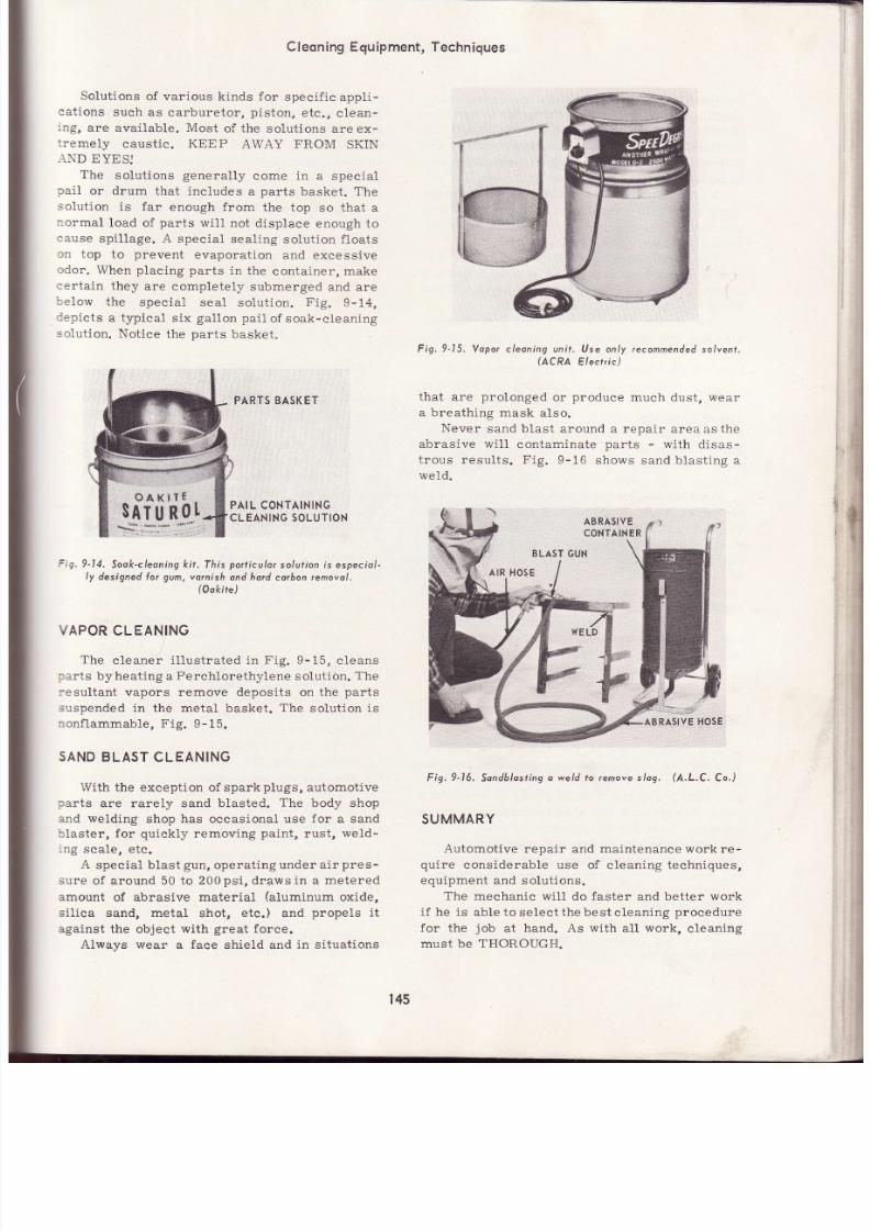
7/26/2019 Auto Service and Repair - Martin W. Stockel
http://slidepdf.com/reader/full/auto-service-and-repair-martin-w-stockel 145/224
Solut ions
of var ious k inds for
speci f ic
appl i -
:at ions
such
as carburetor ,
pis ton,
etc.,
c lean-
.ng,
are avai lable. Most
of the solut ions
are ex-
: remely
caustic. KEEP
AWAY FROM
SKIN
iND
EYES]
The
solut ions
general ly
come
in
a special
¡ai I
or drum
that inc iudes
a
parts
basket . The
solut ion i.s far enough from the top so that a
:ormal
load
of
parts
wi l l
not displace
enough to
:ause
spi l lage.
A special
seal ing
solut ion
f loats
3n
top
to
prevent
evaporat ion and
excessive
:dor.
When
placing
parts
in
the
container, make
'er tnin
thev : rp nnrnnletelv
qrhmeroed
and are
:el .ow
the
special seal
solut ion.
Fig.9-14,
:epicts
a typical
s ix
gal lon
pai l
of soak-c leaning
-.o1ut ion.
Not ice
the
parts
basket .
PARTSBASKET
CleoningEquipment,Techniques
Fig.9-15.
Yopor
cleoning unít.
Use only
recommended
salvent.
(ACRA
Electr ic)
that are
prolonged
or
produce
much
dust ,
wear
a breathing mask
also.
Never
sand blast
around a repair area
as
the
abrasive
wi l l
contaminate
parts
-
with
disas-
t rous
results .
Fig.
9-16
shows sand blast ing
a
we1d.
l;**, ro,,
Fig.9-16.
Sondblost ing
weld to removes/og.
(A.L.C.
Co.)
SUMMARY
Automotive
repair
and
maintenance work
re -
quire
considerable use of c leaning techniques,
equipment and solut ions.
The mechanic
wll l do
faster
and better work
i f
he
is
able to
select thebestc leaning
procedure
for the
job
at
hand. As with
all
work,
cleaning
must
be THOROUGH.
PAIL CONTAINING
CLEANING
OLUTION
=ig,9-14,
Sook-cleoning
ft.
This
port iculor
so/ui ion
is
especiol -
ly
designed
or gum,
varnish
ond hord corbon emovol .
(Ook¡¡e)
VAPORCLEANING
The
cleaner
i l lust rated in
Fig.
9-15,
c leans
:arts
byheat ing
a
Perchlorethylene
solut ión.
The
:esultant
vapors remove deposits on the
parts
suspended
in
the
metal
basket.
The
solut ion
is
: :onf lammable,
Fig. 9-15.
SAND
BLAST CLEANING
With the exception of spark
plugs,
automotive
:arts
are rarely sand
blasted.
The
body shop
and welding
shop
has
occasional
use
for
a sand
'i laster,
for quickly
removing
paint,
rust,
weld-
'no
snnle efn
A
special b last
gun,
operat ing under
air
pres-
sure
of around 50 to
200
psi,
draws in a
metered
amount
of
abrasive material
(alumi.num
oxide,
s i l ica sand, metal
shot ,
etc.)
and
propels
i t
against the
object
with
great
force.
Always wear a face shield and
in
situat ions
QAKIff
$rg-¡-q t
I
,i
ABRASIYE
CONTAIN
R
t45
7/26/2019 Auto Service and Repair - Martin W. Stockel
http://slidepdf.com/reader/full/auto-service-and-repair-martin-w-stockel 146/224
Aüo
Service
ond
RePeir
Hand
brushes
and
scrapers
are
occasionally
useful.
Power
brushes
are
fine
for
removal
of
hard
carbon
from
some
Parts'
Remember
that
many
cleaning
solutions
are
both
toxic
and
caustic
and
must
be
handled
with
care.
A cold solution parts washer is excellentfor
many
parts
not
coated
with
hard
carbon'
Parts
are
soaked
in
an
agitated
solution'
brushed'
r insed
and
blown
drY'
For
larger
ob3ects
or
parts
that
are
hard
to
clean,
a
hot
tank
containing
a
strong
alkaline
sotlrtíor,,
is
desirable.
Aluminum
parts
will
no t
stand
full
strength
hot
tank
solutions'
The
steam
cleaner
is
a
fast
and
efficient
cleaning
tool
and
is especially
good
for
removing
heavy
dirt
and
grease
deposits '
Under-hood
and
,rrrd -body
cleaning
is easily
accomplished'
High-pressrrt
ptty
cleaning
handles
dirt
and grease very well. Large
areas
may
be
cleaned
quicklY.
Low-pressure
spray
cleaning
is
effective
on
many
jobs.
It
is
generally
somewhatslowerthan
either
steaming
or
using
the
high-pressure
washer'
'Ldelyused
Cold
soak-cleaning
solutions
are
wl
for
gum,
varnish,
and
hard
carbon.
removal'
PistJns,
carburetors
and
automatic
transmis-
sions
are
usually
cleaned
in
such
a
cleaner'
A
parts
basket
can
be
furnished
with
the
pail or
drum
of
solution.
Vapor
cleaning
has
some
advantages
and
works
particularly
well
on
certain
parts'
Sand
blast
cleaning
is
useful
for paint' rust
and
weld
scale
removal'
Do
not
operate
a
sand
blaster
near
a
rePair
area'
Cleaning
solutions
canbe
dangerous'
Observe
all
safetY
rules.
SUGGESTED
CTIVITIES
Get
instructions
in
the
use
of'
and
use'
th e
various
pieces
of
cleaning
equipment
in
your
shop.
If
you are
a
student'
visit
as
many
garages
io it l
and
observe
the
cleaning
techniques
,r d.
Al*tys
ask
the
shop
foreman
or
service
manager
first for permission to visit ' Do no t
get in the
way,
do
ot
to ch
equipment
and
avoid
unnece
ssary
conversation'
Upon
leaving'
thank
the
mechanics
concerned
as
well
as
the
manager'
LOOK
'5HARP''
Obviously
mechanics
get
dirty'
There
is
no
need
however,
of
staying-
dirty'
At
the
end
of
each
working
day,
a
thorough
cleansing
of
ihe
hands
with
one
of
the
many
industrial
hand
cleaners
will
restore
your
hands
to
relative
cleanliness.
-
tt .r.
your
uniforms
(coat'
coveralls'
etc')
cleaned
rlgularly.
A
neat
haircut'
daily
shave
andf reshuni formwi l lkeepyoulooking ' 'sharp. ' '
A
garage
must
be concerned about its public
',imag?.
-Tn
¡rritaing,
equipment,_
floors
and
persJnrret
must
all
present
a
favorable
appear-
ance.
Do
Your
Part.
OUIZ
-
ChoPter
1.
Cleaning
often
accounts
for
1/10'
1l5otL12
of
the
total
rePair
t ime'
2.
A shop
with
a
steam
cleaner
really
doesnot
need any other type of cleaning equipment'
True
or
False
?
3.
Piston
ring
grooves
are
best
cleaned
with
the
Power
wire
wheel'
True
or
False?
4.
List
ten
safety
precautions
that
should
be
observed
when
using
cleaning
solutions'
5.
Cleaning
means:
1'
Getting
most
of
the
de -
posits
removed.
2'
Getting
every
single
bi t
of
foreign
material
removed'
Circle
correct
answer.
6.
A cold
solution
parts
washer
is
effective
fo r
hard
carbon
removal'
True
or
False?
?.
When
submerging
a
part
with
an
airtlght
compartment or hollow'
always
place
the
hollow
so
that
the
solution
will
enrer.
B.
The
hot
tank
is
excellent
for
cleaning
engine
bloeks.
True
or
False?
9.
The
solution
used
for
hot
tank
cleaning
is
both
toxic
and
caustic'
True
or
False?
10.
Steam
cleaning
should
be
done
in a
cLosed
area.
True
or
False?
11.
Always
start
the
water
pump
beforelighting
the
burner
on
a
steam
cleaner'
True
or
False
?
12.
To
stop
the
steam
cleaner'
shut
offthe
water
pump
and
when
nowater
comes
fromthe
gun'
trrt-ott
the
burner' True or False?
13.
Keep
the
steam
nozzle
about
one
to
four
inches
from
the
work'
True
or
False?
14.
Cover
the-and
the
------areas
before
steaming
under
the
hood'
15.
List
six
safetylules
to
observe
when
using
the
steam
cleaner'
16.
High-pt t
spray
cleaning
will
doagood
146

7/26/2019 Auto Service and Repair - Martin W. Stockel
http://slidepdf.com/reader/full/auto-service-and-repair-martin-w-stockel 147/224
Cleoning
Equipment,Techniques
1n
job
of removing
dirt
and
grease. True
or
False
?
Gasoline,
or any
flammable, low flash
point
solvent,
if used for
cleaning,
canverylikely
cause a serious
f ire
or
explosion.
True
or
-when
cleaning
under thc
hood, to
pre-
vent accidental short
circuits.
19. Carburetors are
best cleaned
in a strong
alkaline
solut ion such as
that used
in
some
cold soak-cleaning
pails. True
or
False?
20.
Engine
parts
may be cleaned
satisfactori ly
with the sand
blaster.
True
or
False
?
False
?
L8. I t is
a
good
idea
to removethe
f
plynoulh
lour speed
ove¡d¡ive
f¡onsmissíon.
ln
flris
f¡onsmission,
no
plonetary geors ore used to
pro'
du.
on overdrive
eÍÍect.
Fourth
geot, as with
the
offier fáree speeds,
utilizes
convenlionol
geors.
@eorrotios
forthevorious
georsoreiIs¡.3.09toI,2nd-l
.67,3rd-l .00and4¡h-.73to|.
147

7/26/2019 Auto Service and Repair - Martin W. Stockel
http://slidepdf.com/reader/full/auto-service-and-repair-martin-w-stockel 148/224
Auto Service
ond
RePoir
Engine
employing
a
double
overheod comsñolf
setup.
Note
lremispfiericol
combuslion
chomber,
Fiot)

7/26/2019 Auto Service and Repair - Martin W. Stockel
http://slidepdf.com/reader/full/auto-service-and-repair-martin-w-stockel 149/224
Chapter
10
FRICTIONEARINGS
DEFINITION
Bear ings
can
be
classi f ied
as
FRICTION
or
.: . \TIFRICTION.
The
frict ion bearing
contact
irea
SLIDES
(sliding
frict ion)
against
the bear-
:rg
journal
(that
port ion
of a
shaft designed
to
accept
the bearing) surface.
The
antifr ict ion
:earing
(roll ing
fr ict ion)
ut i l izes
ball or roller
: iements
that
ROLL
against the contact
area
:hus reducing fuut not eliminating) fr ict ion.
Both
types are
used in the automobile.
l, Iajor
use of the
frict ion bearing i s confined
to
:he
engine while the antifr ict ion
bearing is used
: l
such areas as the t ransmission,
dr ive l ines,
: : i ferent ia l ,
etc.,
Fig.
10-1.
F RICTION
<-
Fig.10-1.
The
lrict ion beoring uses o sl iding contoc
whi le
th e
ont i { r ict ion
bearing ut i l izes o rol l ing confoct .
ENGINE
FRICTION
BEARINGS
The
camshaft,
crankshaft
and connecting
rods
al l
use
fr ic t ion- type bear ings.
Ant i f r ic t ionbear-
ing applicat ion
in these areas
is largelyconfined
to smal l ,
h igh speed engines
used
for boats,
chain saws, etc.
CASTOR
SPUN ABBITTED
EARINGS
For many years
rnost automobile
engines
used
the
cast
babbit ted
bearing.
The babbit t
(t in,
antimony,
copper)
metal
was melted
an d
poured
into the bear ing area.
It
was then
care-
ful ly bored to a speci f ied s ize, Shims
(thin
st r ips
of steel or brass)
were
of ten
placed
betweenthe
two halves so that as the bear ing became
worn,
they
could
be removed thus reducing
the
clear-
ance.
Fig.
10-2, shows a typical cast
babbit ted
connect ing
rod big end bear ing.
Note that the
bearíng
mater ial
is
bonded
(actua11y
adheres)
to
th^e od.
See
Figs.
10-2, and 10-2-A.
' As engine horsepower and rpm was in-
creased,
the cast
babbit ted rod fai led toprovide
Fig.
I0-2. Cosr
bo66irted connect ing
od .
l0-2A. Typicol
shim
pocks
lor fhe connecl ing
rod ond moín
beorings.
(C/evite
Service)
':¿r.
o
ta ,
<.,.
{J
$. '
-t-
3
zd
E=
149
LAYERS
HELD TOGETHER
BY
A.THINCOAT
OF SOLDER
ALONG
INATIONS.
Fis.
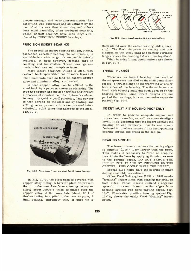
7/26/2019 Auto Service and Repair - Martin W. Stockel
http://slidepdf.com/reader/full/auto-service-and-repair-martin-w-stockel 150/224
proper
strength and wear
c-haracteristics.
Re -
babbitt ing
was
expensive
and adjustment by the
use of
shims
was time
consuming and unless
done
most carefully,
often
produced poor
fits.
Today,
babbitt bearings have been
largely re-
placed
by
PRECISION
INSERT bearings.
PRECISION INSERT BEARINGS
The precision
insert
bearing is
light, strong,
possesses
excelLent
bearing
characteristics, is
available in
a
wide
iange
ofsizes, andis
quickly
replaced. It
does however,
demand care in
handling
and installation.
These
bearings are
made in
both one
and
two-piece
t¡pes.
Most
insert bea rings uti l ize a steel
(low
earbon) back
upon which
one or
more layers of
other
materials such
as lead-tin
babbitt, copper
alloy
and aluminum
alioy,
are
bonded.
A lead-copper
alloy
can be
affixed
to
the
steel back by a process known as sintering. Th e
lead and
copper are melted
togetherandthrough
a
process
of
atomization, this mixture
is reduced
to very
tiny
(.002
' .005)
particles.
This powder
is
then
spread
on
the
steel and
by heating,
and
roll ing
under
pressure
it is
compressed into
a
relatively
solid
layer that adheres
to the
steel,
Fig.
10-3.
Fig.
0-3.
Five
oyer
counting
teel
6ocft)nsert
earing.
In Fig.
10-3, the
steel
back is
covered
with
copper all.oy lining.
A
barrier
plate
(to
prevenr
the
tin in the
overplate
from
enteringthecopper
alloy)
about
.000075
thick
is
plated
over the
copper alloy.
A
thin overplate
(about
.001)
of
tin-lead
alloy is applied to the
barrier
plate.
A
final
coating,
extremely thin,
of
pure
tin
is
rrFFr
STEEL
STEEL S
- '- \
BAEElrr
I
¡ lutltxulr l lur 'rxulr
frffi(ffir
\\N\\)
COPPER
ALLOY
/
BARRTER
-€
?LATE
BABB TI BABBITT
Fig,
10-5.
Somenserfbeoringining
com6inotions.
flash
plated
over the entire bearing
(sides,
back,
etc.). The flash
tin
prevents
rusting
and oxi-
dization
of the steel back
and
parting
surfaces
(edges
where
the bearing halves
come
together).
Other
bearing
lining combinati.ons are
shown
in Fig.
10-5.
THRUST LANGE
Whenever
an insert bearing
must
control
thrust
(pressure
parallel
to the
shaft
centerline)
forces,
a
thrust flange
is incorporated
on
one
or
both sides
of the bearing.
The
thrust faces
ar e
Iined
with bearing material
such
as used
on
th e
bearing
proper.
Some thrust flanges
are not
part
of the bearings, but
are
inserted
as
separate
RiecelF ig.
l0-6.
INSERT
MUST FIT
HOUSING
PROPERLY
In
order to
provide
adequate
support and
proper
heat transfer,
as well
as accurate
align-
ment, it is
essential
that the insert
contact the
housing
or cap
properly.
Inserts
are manu-
factured
to
produce
proper
fit by
incorporating
bearing
spread
and crush in the design.
BEARING SPREAD
The insert
diameter aiross the
partingedges
is
slightly
(.005
- .030)
larger than the bore.
This
makes it
necessary to
force
or snap the
insert into the
bore by applying thumb
pressure
to the
parting
edges.
DO NOT FORCE THE
INSERT
INTO PLACE BY PRESSING ON THE
CENTER.
THIS
COULD
WARP THE INSERT.
Spread also helps hold the bearing in
place
during assembly
operations.
Older Ford V-B engines
(1932
- 1948)useda
floatingtt
insert
l ined
with bearing material
on
both sides.
These
inserts uti l ized a negative
spread to
prevent
insert
parting
edges
from
hooking
against
rod bore
parting
edges.
Fig.
10-7,
i l. lustrates
posit ive
bearing
spread.Fig.
1O-?A, shows the early
Ford
floating
insert
setup.
t50

7/26/2019 Auto Service and Repair - Martin W. Stockel
http://slidepdf.com/reader/full/auto-service-and-repair-martin-w-stockel 151/224
Frict ion
Beorings
BEARING
RUSH
The
insert is
is snapped into
protrude
a slight
edge.
In
effect,
larger
than
a
full
also designed so that
after
it
p lace,
the
part ing
edges
wi l l
amount above the bore
part ing
each insert hal f is
s l ight ly
hal f
c irc le,
Fig.
10-8.
Füg.
I0-7A.
This
eorly Ford
Y-8 connecting
rod beoring
o
negolive bearing spreod.
PARTINGEDGES
Fig.
l0-8.
Beoring
CRUSH.
Nofe fhot
6ofh insert
port ing
edges
(exoggeroted
or
emphosis)
protrude
slightly
oóove
tfie
cop.
When
the bearing
is bolted
together, the
crush area touches f i rs t .
As t ightening
pro-
gresses,
the
crush area is forced beneath
the
bore
part ing
edges
thus
creating
a t ight insert
to bore
contact
through
radial
pressure,
Fig.10-9.
NEVER FILE
BEARING
CAPS
OR
CRUSH.
TO DO
SO
MAY RUIN
THE BEARING.
INSERTMUST
NOT TURN
With the exception
of
the floating insert
mentioned, inserts
are
provided
with
locating
lugs or dowels to
prevent
the insert from turn-
ing.
WHEN
INSTALLING
INSERTS, BE
CER-
TAIN THE LUGS ARE
PROPERLY ALIGNED
WITH
THE
SLOTS
IN
THE
HOUSING.
DOWELS
MUST ENTER
THEIR HOLES.
See
Fis. 10-9A.
INSERT
NDHOUSINGORE
MUST
BE
SMOOTH
ND
CLEAN
The
housing bore and insert back and
parting
surfaces, must be free of nicks, burrs or
foreign
material.
If
the insert is
prevented
from making
perfect
contact,
pressure
spots,
misalignment and
overheating
will result.
AL-
WAYS CAREFULLY CHECK
THE HOUSING
BORE
AND
INSERT BACK
TO MAKE
CERTAIN
THEY
ARE SMOOTH AND CLEAN.
DONOTOIL
THESE
SURFACES.
Fig. l0-6.
Cronkshoft
moin beoring
with th¡usl
(Clevi¡e
Service)
l longes.
l0-7.
Posi¡ive
beoring spreod. Nofe fñol diamete¡
A
oc¡oss
porling
surfoce is o trille lorger thon bore diomere¡ B.
,Ó
F,g
u¡i ized
t5 l

7/26/2019 Auto Service and Repair - Martin W. Stockel
http://slidepdf.com/reader/full/auto-service-and-repair-martin-w-stockel 152/224
HOUSING
ORE
HALVES
MUST
BE ALIGNED
Even
though
bore
and insert
are
clean, in-
sert
spread
and
crush
correct,
the bearing
wil l
sti l l
be ruined
if
the
upper
and
lower
(in
the
Fig. l0-9A,
Locoting
lugs
ond dowels
fteep ñe insert
lrom turniig.
case
of
split
bearings)
bore halves
are not
properly
aligned.,
It is possible
to reverse
some
bearing
caps
0ower
halves).
This
will
shift
the
upper
and
lower
bores
out ofalignment.
WHEN
DISASSEMBLING
BEARING
CAPS,
AL-
Fig l0-9.
llhen ¡od
ond
cop ore
drawn
together
as in
B,
the
beoring
crusfi,
os
sáown in
A,
produces
rodiol
pressure
lorcing,izsed
tightly
against
the
bore.
WAYS
MARK
THE
UPPER
AND
LOWER
HALVES
(BEFORE
REMOVAL)
PREFERABLY
WITII
NUMBERS
SO
THAT
YOU
MAY
REPLACE
TH E
CAP
IN
ITS
ORIGINAL
pOSITION.
See
Fig.10-10.
The
inserts
should
always
be
saved
fo r
study.
If
they
appear
usable,
mark
them
on the
back
with
a fine
scribe.
If plans
include
re-
placement,
you
may mark them on the bearing
surface.
WRENCH
SIDE
PRESSURE
CAN
ALSO
DESTROY
AP
ALIGNMENT
Thick
wrenches
can
create enough
pressure
against
the
cap to
shift
it
out
of
alignment¡
Use
correct
size
socket
and
tighten
by
alternating
from
one
bolt
or nut
to
the
other.
WHEN
CAp
IS
JUST
SNUG,
TAPLIGHTLYWITIIAPLASTIC
HAMMER
TO
ASSIST
CAP ALIGNMENT.
USING
A TORQI]E
WRENCH,
TORQUE
THE
FASTEN-
ERS
TO
THE
RECOMMENDED
VALUE,
Fig. 10-11.
HOUSING
ORES
MUST
BE
ROUND
The
heavy
stresses
within
the
engine
ca n
cause
the housing
bores
to
elongate.
When
th e
insert
is
installed
in
such
a bore,
it
wil l
con-
form
to
the
bore
elongation
thus providing
an
Auto
Service
qnd
Repqir
CRUSHHEIGHT
EACH
HALF
BEARING
PRESSURE
i
I
I
LOCATING
LU G
152
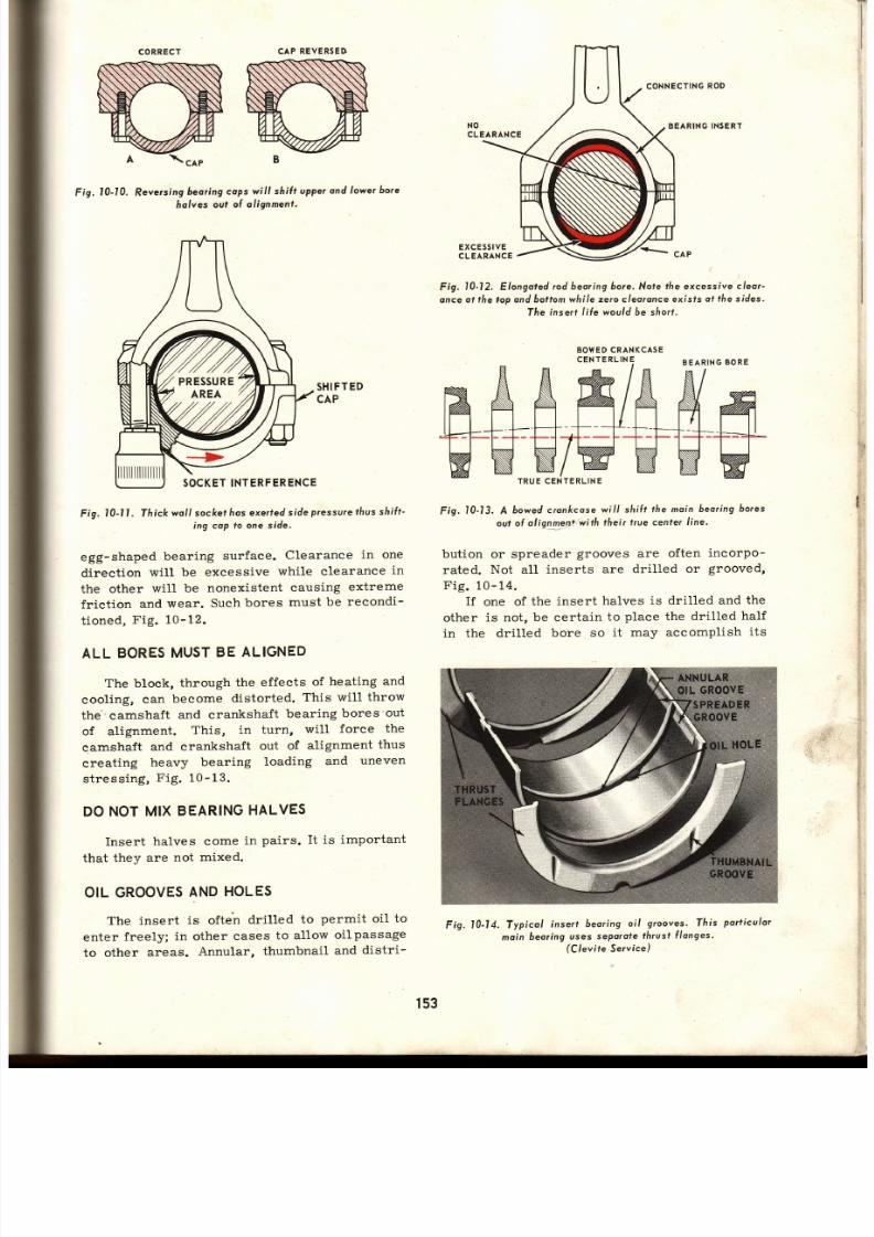
7/26/2019 Auto Service and Repair - Martin W. Stockel
http://slidepdf.com/reader/full/auto-service-and-repair-martin-w-stockel 153/224
CORRECT
I
AP
REVERSED
Fig.
10-10.
Reversing
beoring cops
will
shiÍr upper
ond
lower
bore
fiolves
ouf
ol alignment.
SHI
FT ED
CA P
Fig.
t0-t l . Thick
woll sockef
hos
exerfed
side
pressure f ius sf i i f t-
ing
cap to
one
side.
egg-shaped
bearing
surface.
Clearance
in one
direct ion
will
be excessive
while clearance
in
the other
wil l be
nonexistent
causing
extreme
frict ion
and
wear. Such
bores
must
be
reeondi-
t ioned,
Fig.
10-12.
ALL BORES
UST
E
ALIGNED
The block,
through
the
effects
of heating
and
cooling,
can
become
distorted.
This
wil l throw
the camshaft
and crankshaft
bearing
bores out
of alignment.
This,
in
turn,
will
force
the
eamshaft
and crankshaft
out
of
alignment
thus
creating
heavy
bearing
loading
and
uneven
stressing,
Fig.10-13.
DONOTMIX
BEARING
ALVES
Insert halves come in pairs. It is important
that they
are
not
mixed.
OIL
GROOVES
ND
HOLES
The insert
is
often
dril led
to
permit oil
to
enter
freely;
in other
cases
to allow
oilpassage
to
other
areas.
Annular,
thumbnail
and
distr i-
CONNECTING
OD
BEARING
NSERT
Fig.
I0-12.
Elongoted
cd
beoring 6ore. Note
l f ie
excessive
cleor-
once
ol l lre
top
ond boltom
while
zerocleo¡once
exisls
ol the sides.
The
insert l i Íe would 6e sf iort.
BOWEDCRANKCASE
Fig.
t0-13. A
óowed cronkcose
wil l shi{¡
the moin
beoring
6ores
out o( olignnen+:with
thei¡
l¡ue cenle¡
line.
bution or spreader
grooves
are
often
incorpo-
rated.
Not
all
inserts
are
dril led or
grooved,
Fig.
10- 14.
If
one
of the
insert
halves is
dri l led and
th e
other
is not, be certain
to
place
the
dril led
half
in the dri l led bore so it may accomplish it s
;i-
:, ,{
:.1¡
.
:
F ig. l0-14.
Typicol
inserl
beoring
oil
grooves. Thís
portículor
moin
beoring
uses
seporote
hrust
Í longes
(Clevite
Se¡vice)
t
I
ti
,i
EXCE55tVE
CLEARANCE
INT ERF
ERENCE
ls3

7/26/2019 Auto Service and Repair - Martin W. Stockel
http://slidepdf.com/reader/full/auto-service-and-repair-martin-w-stockel 154/224
Auto Service
ond
Repoir
purpose.
Neglect ing
to do
this can
cause
im -
mediate
bearing failure.
When install ing
full
round inserts,
such
as the camshaft bearings,
make
sure the oil holes
are aligned,
Fig.
10-15.
Fortunately,
many
split bearings
are
manu-
factured
with
both halves
dril led to
prevent
im -
proper
assembly.
INSERT
ILHOLE
DOWN.
IL BLOCKED
Fig. l0-15. Align insert o i l with
oi/
possoge.
A-lnsert o i l
hole
lros 6een
placed
down hus cutt ing
oll o i l supply.
8-lnserf
oi l hole
oligned wilñ
possogewoy,
Proper
ubricotion wil l resul¡.
BEARING
IL CLEARANCE
The precision
insert bearing
must have
enough
clearance
to
allow oil to
penetrate
an d
form
a lubrieat ing
f i lm.
The
clearance
must
be sufficient to
provide proper
flow
through the
bearing
to aid
in
cooling
and
passage
to other
crit ical areas
receiving
their lubrieat ion via
a
part ieular
bearing.
On the other hand, too much clearance will
allow an oil fLow that
can lower oil
pressure,
eause excessive
"throw
off"
(oil
running
from
bearings
and
being
thrown off
the
crankshaft
at
high veloeity) that in turn will
flood
the
cylinder
walls
beyond
the
capacity of the
piston
rings
to
control.
Excessive
clearance
will
also
allow
movement between
parts
sufficient enough
to
literally
pound
the bearing to
pieces.
RtcotttilDEo [. Gtttnil{cts
SHAFf-SIZT
s8
(H¡gh
ea d
or tin base)
CA
(Copper
Alloy)
AP&CP
(0ver lated
bear¡ng)
AI
u
mtnu
Alloy)
2
-2lt
.0010
.mm
.0010 .0025
2t%¡-3Vz
0015
0025 0015
0030
3e/rs
4h
0020
.0030
0020 0037
NOTI:Chart bove
ndicatesininumiamelrallearances.or
maximum
ermiss¡ble
learance,dd
001"
Fig. l0-16. Typicol
oveÍoge
minimumcleor-
onces for
engine
óeorings.
(Federol-Mogul)
WHEN
INSTALLING INSERT
BEARINGS,
ALWAYS
FOLLOW THE
ENGINE MANUFAC-
TURES
RECOMMENDED
BEARING
CLEAR-
ANCES.
The
chart
in Fig.
10-16,
shows AVERAGE
MINIMUM
CLEARANCES
for engine bearings
of different
sizes
and types.
The
chart
is in-
tended to indicate average clearances only, an d
should
not be used when
engine manufacturersl
recommendations
are available.
CHECKINGEARING
L
EARANCE
Approximate
clearance of engine bearings
can
be determined by
attaching an
engine
"pt"-
lubricator"
(air
pressure
operated oil tank)
an d
observing the
amount of oil
dripping from the
bearings.
This
is
often done after the
pan
is
removed, but
before disconnecting any bearings
to
give
the
mechanic
an approximate
idea
of
bearing condit ion. The prelubricator is used
again after engine assembly
primarilyto
charge
the lubrieation
system
with
oil but will at the
same t ime,
provide
a
final
visualcheck onbear-
ing clearances.
-
-,-/
One
of the
most widely
used
methods of
ob -
taining
precise
clearance
measurements is
th e
use
of a special
plast ic
wire
(trade
name
Plast igage). A
section
is
placed
either
on the
journal
or on
the i.nsert, the bearing is
t ight-
ened, then removed.
The plast ic wil lbe
f lattened
and
y
using a
paper gauge
supplied
with
th e
wire, the width
of the
wire
can
be
accurately
related to clearance in thousandths of an inch,
Fig.10-17.
PAPER
GAUGE
FLATTENED
PLASTI
GAGE
Fig.
l0-17.
Clrecfti;g
beoring
cleoronce
with Pldstigage.
Beoring
ños .003 cleo¡once.
Complete instruction
on
the use
of
the
pre-
lubricator and
Plastigage will
be
given
ín
the
chapter
on engine overhaul.
154

7/26/2019 Auto Service and Repair - Martin W. Stockel
http://slidepdf.com/reader/full/auto-service-and-repair-martin-w-stockel 155/224
I
UNDERSIZEEARINGS
In
order
to compensate
for
wear, inserts
ar e
available in a serles
of undersizes.
If
the
journal
wear is
slight,
the
recommended
clearance
ca n
often be obtained
through
the use
of
inserts
.001
or.002 unders ize.
The
shaft
must becare-
ful1y
measured and
the largest
diameter com-
pared
to the
original size
in order
to determine
the
correct
unders ize.
When
journal
wear is severe
orwhenjournals
are scored or
egg shaped,
inserts are
available
in.010,
.020, .030,
etc.,
unders ize.
The
shaf t
is
ground to one of these undersizes thus bringing
the
bearing condit ion
and clearance
up
to accept-
able standards.
Occasionally
semif inished
(greatly
under-
s ize) inserts
are bored
out to a
speci f ied
size.
PREC¡SION ULL
ROUND
CAMSHAFT
BEARINGS
The
camshaft
bearing
is constructed
quite
like
the
connecting
rod and
crankshaft
inserts
except
being of
one
piece
design.
The
camshaft
bearing
must be
pressed into
p1ace. In addit ion to the standard sizes, theyare
available
in large
undersi2es
to
permit
l ine
boring
(attaching
a cutter
to a long,
rigid
steel
bar and
passing it
through
the bearings
one after
the
other
thus
boring
them
in l ine
with each
other)
after
installaticin.
The
bearing
material
is
aff ixed
to steel
str io stock and
the stock
is rolled
into
a
full
c i rc le with ei ther a but t or but t andcl inch joint .
The
bear ing
mater ia l is
usual ly babbit t ,
Fig.10-18.
BUSHINGS
Bushings
are
full
round bearings, usually
made
of solid bearing
bronze
(mixture
of cop-
per,
lead, t in, z inc, etc. ) .
They
can also
be
made by the sintering
process. Although some
appl icat ions
use
steel
back
precis ion
bushings;
in
general pract ice,
the bushing
is
pressed
into
place
and ei ther
bored, reamed orhonedtosize.
Bushings are usually of smaller diameter than
bearings and are
used
for
slower
speed appli-
cat ions,
Fig.10-19.
Fig.10-19.
Typicol
Aushings'
These
ore
the stee/
bocked
pre-
cis ion
fYPe.
Frict ion
Beorings
Fig. l0-18. Typicol
camshoÍt
nserl beorings.
(Clevite
Service)
l
I
¡
{
I
f
i
i
{
r55

7/26/2019 Auto Service and Repair - Martin W. Stockel
http://slidepdf.com/reader/full/auto-service-and-repair-martin-w-stockel 156/224
ROUND
A
SfRAIGHT
AB
'HM
r \ \ l l / /¿
'N H
AA B
EGG
HAPE
TAPERED
SCORED
Fig.
I0-l 9A.
Beoring
ournols
musl
be
round,
straight, ond smooth.
BEARING
OURNALS
The
section of a shaft
that
contactsthebear-
ing
surface is
termed
a
JOURNAL.
It
must be
ROUND,
SMOOTH and STRAIGHT. Nicks,
scratches,
etc.,
wil l
ruin the bearing inaterial,
Fig.
10-19.A.
It
is
recommended
that a surface
finish
of
16 micro inches or
smoother be
attained.
Th e
micro inch
(one-mill ionth
0.000001
of an
inch)
is
used
as a
measurement
of
surface
finish. To
measure
a surface
finish
in micro
inches, tests
are made to determine the depths of allgrooves
or
scratches. The RMS
(root-mean-square)
or
AA
(arithmetical
average) is
used to
find
the
AVERAGE
depth. For practical purposes,
this
amounts
to about
one-third of the maximum
depth. In Fig.
10-20,
you
will
note that the red
line indicates
one-third the maximum
depth.
If
Auto
Service
qnd
Repqir
the
maximum
depth
is
g0
micro
inches,
the
measuring
device would
indieate
a
finish
of 30
micro
inches.
HANDLING
EARINGS
Precision
insert
bearings
are
just
what
th e
name implies - they are PRECISION units and
should
be
handled
with
utmost
care. Do not mix
halves, protect
from
dirt
and
physical
damage.
Keep
fingers
from
bearing
surface
as finger
marks
can
cause
fine
surface
corrosion..
When installing,
never force
or
pound
into
place.
Make
certain bore
and insert ' is
spotless.
Locating
lugs
(sometimes
called tangs)
should
be in
place.
After install ing,
coatbearing
surface
with
CLEAN
engine oil. Never
file
an insert.
Always
check for
proper
clearance.
BEARING
AILURE
A
bearing
of the
correct
size and
t¡npe,
properly
fitted
to an
accurate housing
bore
and
operating
against
a smooth,
round
shaft, will
under
normal
operating
conditions,
last in
ex -
cess of 50,000
road mi les.
There
are however,
many
things
or
comtri-
nation
of things,
that will
cause
premature
failure.
It
is important
that
the mechanic
under-
stand
the most
signif ieant
ones as well
as being
familiar
with
the
visual effects these
have
onthe
bearing
insert. In
this way,
by
close
study of the
damaged
bearing,
the
cause
witl
often be
ap-
parent.
In
any
case,
whenever
an engine is torn
down,
bearings
should
always
be
cleaned and
carefully inspected.
DANGER
SIGNALS
Bearing
failure
is
generally
preceded
by
a
lowering
of oil
pressure
due
toincreasedclear-
ance. The
engine
oil
consumption will rise from
excessive
oi1 throw
off and finally
as
the
clear-
anee increases,
the
bearings will
starttoknock.
DIRT,
THENUMBER
NE
CAUSE
OF BEARING
AILURE
Field
and laboratory
studies,
over a
period
of many
years,
have
been
summed
up relative
to
the
causes of
bearing
failure
and the
per-
eentage
of
failures
attr ibuted
to each
cause.
From
the results
of
these studies, Fig.
10-21,
you
will
note
that
DIRT
is
by far
the most
fre-
quent
cause of
failure.
ig,
l0-20. Determining surloce
linish rn
MICRO ,NCHES.
l5ó

7/26/2019 Auto Service and Repair - Martin W. Stockel
http://slidepdf.com/reader/full/auto-service-and-repair-martin-w-stockel 157/224
DIRT
The
word
dirt,
as used
to describe
foreign
particle
damage
to moving
parts,
includes
sand,
cast
iron
and
steel
chips,
pieces
of
bronze,
grinding
stone grit,
etc. NORMAL
engine wear
will
produce
fi.ne
parti.cles
worn fromthe
various
parts. Normally these are removed via the oil
filtration
system. They
DO
contribute to
engine
wear
but
at
present
will
not
be emphasized.
ABNORMAL
engine
wear wi l l produce
LARGE
bits of dirt
that will
greaily
accelerate
the
wear process.
DIRT
FROM
RECONDITTONING
Valve
grinding,
cylinder boring
and honing,
shaft grinding,
etc., deposit
metal
andcorundum
(abrasive
particles).
These
MUST
be removed
by
thorough
cleaning.
(See
chapter
on
cleaning
processes.) There is always the possibil ity of
machined particles
being
present
innew
engines
also.
DIRT
FROM
CLEANING
A
sloppy
job
of
cleaning
oftenloosenscarbon
and
other
deposits
but fai ls
to
completely re-
move
them.
Once
the engine
is
assembled
an d
put
into
operation,
the washing
and
cleaning
action
of the
oil wil l
cause these
deposits to
reaeh
the
bearings.
REMEMBER:
DO NOT EX-
PECT
OIL
FILTERS,
EVEN
THE
FULL-FLOW
TYPE,
TO
COMPLETELY
PROTECT
TH E
BEARINGS. THEY CAN CLOG, THUS
FORCING
THE
BYPASS
OPEN
AND
CHANNEL LARGE
CHUNKS
OF
DIRT
DIRECTLY
INTO
TH E
BEARINGS.
Final
rinsing
in dirty
solvents
often
contaminates
parts.
DIRT
FROMPOOR
WORK
ND
STORAGE
ONDITIONS
The
engine may
be
contaminated
by
working
under
dusty
condit ions
or by
careless handling
CAUSES OF
BEARING
FAILURE
Dir t . . . .
. , . . . . .42.90%
fnsufficienlLubricotion
.,.,15.30%
Misossembfy
. . . . .13.40%
Misol ignnent
.....9.80%
Overlooding.
, . . . .
8,7O%
Corrosion
. . . . . . .4 .507
Indeterminqfeond Other Couses.
. . . ,
5.40%
Fig.
10-21.
Couses
of
beoring Íai l-
u¡e ond the
percenloge
of occurence.
of parts.
Keep
clean
parts
covered
until
ready
for
installation.
Work in
a CLEAN
area,
pro-
tected
from
windborne
dust.
When
not working
on
a
part,
even for
a
few
minutes,
throw
a
cover
over it.
Keep
hands
and ools
(especially
sockets)
free
of dirt
when
assembling parts.
Avoid
the
use of
the
air
gun,
sandblaster
or steam
cleaner
near open engines or other units.
DIRT
FROMEXTERNAL
OURCES
Once
the
engine is
assembled
and
plaeed
in
serviee,
dirt
can st i l l
enter.
Some
of the
most
eommon
sources
are through
the
air
cleaner,
breather
system, fuel
system,
cooling
system,
dip
st ick
and
lubricat ion
system. The
vacuum
lines
can also
be
offenders.
Cover
carburetors
when
the
eleaner is
re -
moved.
Keep
air
cleaners
elean
and
properly
serviced.
CIean
and
properly
service
crankcase
br:eather systems. Maintain a good filter in th e
fuel
system.
Check
for
coolant leaks
into
th e
cylinders
(ethylene
glycol
ant ifreeze
forms
a
gummy
residue
in
the
bearings
and rings
an d
will
cause serious problems).
Never
lay
a dip
st ick
on
a dirty
surface.
Wipe both
st ick
an d
area
around
stick
entry
hole
before
returning.
When
changing
oil f i l ters,
wipe
contact area
thoroughly.
Oil
filler
cans
and spouts
should
be
cleaned
and stored
to
prevent
contamination.
When
removing
drain
plugs,
clean them
thor-
oughly
before
replacing.
Keep
''bulk
oil tanks
clean. Wipe
the surface
of oil
cans
before
puncturing. Check fi l ler tube for dirt before
adding
oil.
Why
such
a
fuss
about
dirt? Once
again:
DIRT
IS THE
MECHANICS
WORST
ENEMY.
GET IT
OUT
OF THE
UNIT
AND
USE EVERY
PRECAUTION
TO
KEEP IT
OUT.
Study
th e
bear ings
shown
in
Fig.
L0-22.
Each
one was
damaged
by dirt .
BEARING
UBRICATION
AILURE
Low
oil
pressure
caused by worn
bear ings,
faulty
pump,
clogged
pi.ckup
screen
or an in-
sufficient supply of oi1 wil l cause rapid failure.
Dry
starts
(engine
overhauled
and
started
without
charging the
oil system with
oil under
pressure
thus
allowing
the bearings
to
operate
until
pump
forces
oil throughout
the system)
can
eause
initial
damage
that wil l
cut
down
the
life
expectaney of
the bearings.
Loss
of
oil through damage
to the
pan,
FrictionBeorings
t57

7/26/2019 Auto Service and Repair - Martin W. Stockel
http://slidepdf.com/reader/full/auto-service-and-repair-martin-w-stockel 158/224
l0-22.
Dir t
rv ins beorings
-
FASTI A Dirt
enbedded
plated
beoring,
B-Dírt
inpregnotedbabb¡tt
beoring.
wffi
= t .
10-23.
Aluminvm
beorings
ruined lrom
Iock oÍ Iubricotion.
(
F
ederol-Mogul
)
-
rkpn nrrmn or I ne.
leakíng sasket. or
f
a i lure
--__- ,
--
: .
replace
plug
after
dra in ing,
wi l lcause
sudden
:ar lure,
F ig.10-23.
BEARING
FAILURE
FROM
IMPROPER ASSEMBLY
\s
al ready
ment ioned,
d i r t
on
the insert
. :ck,
insuff ic ient c learance,
reversing
caps,
¡ iacing a lower
insert
in the upper
posi t ion,
io* ,ed
crankcase,
sprung
shaft
or
rods,
etc. ,
, r -11
ause
bear ing
fa i lure.
F lgs.
10-24A,
B, C,
l ,
E, F,
G,
i l lustrate
the
resul ts.
ffi
.r,
a
W:
Fíg,
10-248.
Nicked
qnd
dented
cop bore wil l
tronsler morks
lo
the 6ock
oÍ the ínsert
fhus cousing
locol ized
high
pressure oreos.
OIL
HOLE
OIL PA5SA:
rl i lr i
IMPRESSIC\
i i l
INSERT
B¡
I,
Fig.
10-24C.
The
upper
insert, with
oi l hole, wos
instol/ed in
fhe
boftom
posit ion
The
lower nsert
(see
oíl
possogewoy mpression
on back)
6locked the
low ol o i l
to the beoríng.
Fig.
l0-24D, A
nisol igned
connecting
rod
ploced one side
of this
ínse¡l under
P¡essure.
Nofe
loi lure
o¡eq.
rt
q
r
ilr
FAILURE
AREA
Fíg.
10-24A.
Bearingdomoge
rom
toperedhousing
bore.
1s8
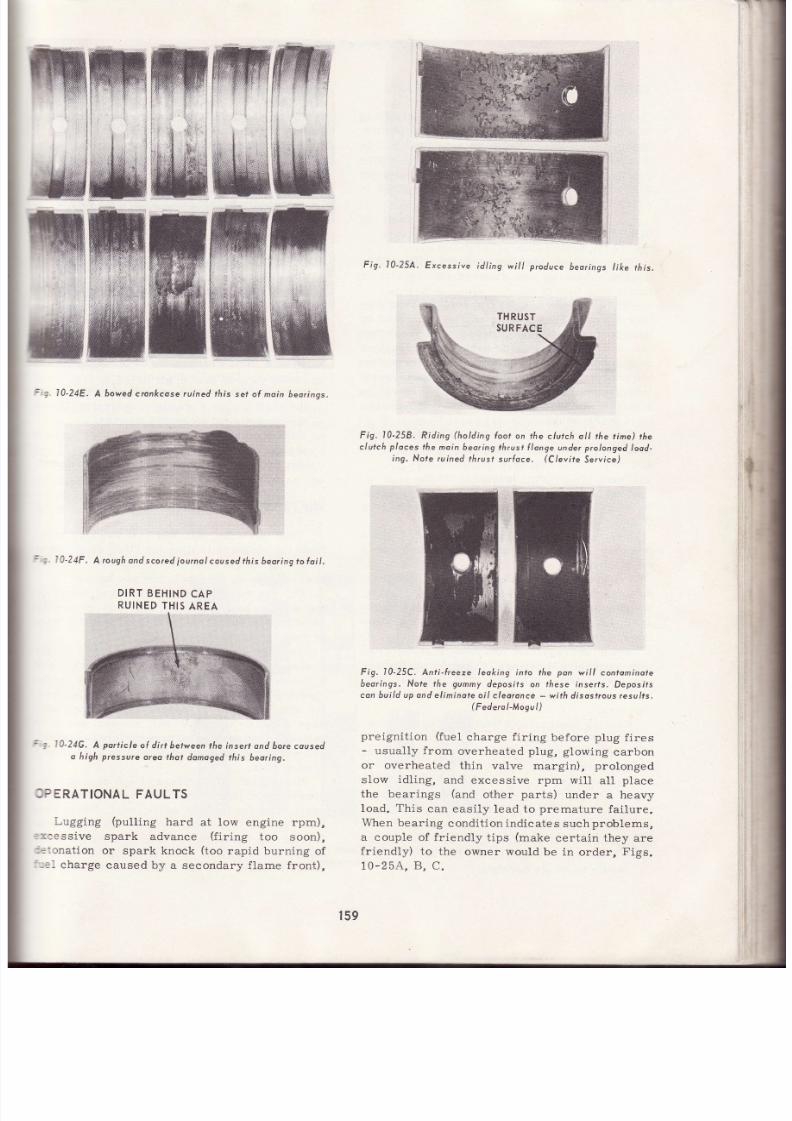
7/26/2019 Auto Service and Repair - Martin W. Stockel
http://slidepdf.com/reader/full/auto-service-and-repair-martin-w-stockel 159/224
: . 10-24E,
A bowedc¡onkcose uined
¡his
set of moi n 6eo¡inqs.
:
i 0-24F.
A rough
ond scored
ournol
coused his beoring
ofui l .
DIRT
BEHIND
AP
RUINED
HIS
AREA
:
iA-24G.
A
porr ic le
ol d ir t between
he insert
ond 6orecoused
o f i igñ pressure
oreo that
domoged his
beoring.
FAULTS
Lugging
(pull ing
hard
at low
engine
rpm),
spark
advance
(f i r ing
too
soon),
or
spark knock
(too
rapid burning of
, .1
charge
caused
by a secondary f lame front),
Fiq. l0-25A.
Excessive
idl ing
wil l produce
bearings
ike
r / r ¡s
Fig.
l0-258.
Riding
(holding
{oot
on
the clutch ol l
the t ime)
th e
c/ufclr
p/oces
the moin
beoring thrust
longe
under
prolonged
ood-
ing. Nofe
ruined th¡ust
surfoce.
(Clevite
Se¡vice)
F¡g. 10-25C.
Anti- lreeze leoking into the pon
wil l contominote
beorings.
Nore
rhe
gummy
deposits on tÁese inserfs.
Deposifs
con bui ld up ond
eliminate oi/ c/eoronce
-
with disostrous resu/ts.
(Federol-Mogul)
preigni t ion
( fuel
eharge
f i r ing
before
ptug
f i res
-
usual ly f rom
overheated
plug, glowing
carbon
or overheated thin valve rnargin), prolonged
slow
idling,
and excessive
rpm
will aII
place
the bearings
(and
other
parts)
under a heavy
Ioad. This
can
easi ly lead to
premature
fai lure.
When
bear ing
condit ion indicates
such
problems,
a couple of fr iendly
t ips
(make
certain they are
fr iendly)
to the
owner would
be in
order.
Fios-
1o-254,
B,
C.
- t
i
159

7/26/2019 Auto Service and Repair - Martin W. Stockel
http://slidepdf.com/reader/full/auto-service-and-repair-martin-w-stockel 160/224
Auto
Service
ADDITIONAL NFORMATION
Checking
bearing clearance,
determinÍng
bearing
size requirements,
prestart
lubricat ion,
bearing
installat ion and
torquing,
etc.,
wil l
be
discussed
in detail
in the chapter
on
engine
overhaul.
Steel
and
rubber suspension
system
bushings will be covered in the chapters to
which
they
pertain.
SUMMARY
The
frict ion bearing operates
with sliding
frict ion.
Frict ion is reduced
to acceptable
limits
by a
f i lm
of
oil.
Most
modern bearings
are of
the
precision
insert type.
They
can
be of
the
full round or
split-halves
type.
They
util ize
steel backs
that
can
be
faced
with
lead-t in
babbit t , copper
alloys
or aluminum
alloy.
The
bearing
¡haterial
is
often
aff ixed by sintering.
Some
bearings
have several
layers
of dif ferent
materials.
End thrust
is
controlled
by incorporat ing
thrustf langes
on one
or
more
bearings.
The
insert
must
have int imate
(close)
contact
with
the
housing bore.
Bearing
spread,
crush
and cleanliness
assure
a
proper
f it .
Never
f i le bear ing
inserts
or caps.
Locating lugs
should
be
in the
proper
slots.
Bearing back and'bore
,must
be
clean
and
free
of
nicks op
foreign material.
Never
reverse or
mix
bearing caps.
Tighten
properly
using
a torque
wrench.
Check bores
for alignment.
Oil grooves and holes are vithl. They must
be
located
properly when
instáll ing
inserts.
Bearing clearance
is
crit ical.
An
average
clear-
ance
would be around
.002.
Follow
n¡anufac-
turerrs
recommendations.
{
Worn or
reground
journals
must be
f it ted
with undersize
bearings.
Common
undersizes
are:
.001, .002,
.003, .010,
.020,
.030
and.040.
Semif in ished
inserts
may be
bored
to a
speci-
f ied
size.
Bear ing c learance
is best cheekedwithplas-
t ic
wire
(Plast igage).
Camshaft
bearings
are
of the
full-roundtype,
usually babbit t l ined.
Bushings are
usuallybronze
or bronze-faced
steel,
and
are
bored,
reai¡ed
or
honed
to size.
Journals
must be
round,
straight
and
smooth.
The micro
inch is a
unit of
measurement
used
in describing
surface
finish. A
microinchfinish
of 16
or
better
is required
for
journals.
Handle bearings carefully.
qnd
Repq¡r
Bearing failures
are
most often caused
by
dirt.
Low
oil
pressure,
excessive
oil
con-
sumption and
knocking, are
danger signals
that
indicate
excessive
bearing
wear.
Dirt
enters
the engi.ne
from normal.
wear,
reconditioning,
cleaning,
poor
work
and storage
conditions,
through
the fue1,
cooling,
lubrication,
vacuum and ventilation systems.
Inadequate lubrication,
improper assembly,
and
improper driving
habits also cause
bearing
failure s..
SUGGESTED
CTIVITIES
1. Check
the clearance
in
a
bearing,
using
Plast igage.
-
.
2.
Examine a number
of bq4|ing
failures
and
see
if
you
can
determine the
cause or com-
binatíon
of
causes.
3.
Mike
a
used crankshaft,
both
main and rod
journals.
Using
manufacturerrs specif ica-
tions,
determine the amount
of
wear.
Would
the
shaft
accept
a standard
undersize
?
Check
the
journals
for nicks and
scoring.
4.
Make
a
collect ion
of
bushings,
full-roundand
split . Study
their construct ion
and see
if
yo u
can
determine the
type of beari.ng
material.
WHOTS AUGHING?
Your favorite suit
has
just
been
returned
from the cLeaners
n time
for
thet'
dange.
Upon
removing
the
garment
cover,
you discover abig
grease stain on the lapel. Are you happy?
Or,
you
have an
important
engagement.
On
the
way, to look
your
best,
you stop
for
a
quick
haircut.
The barber drips
hair oildownthefront
of
your
shirt.
Are
you
happy?
You are
probably about as
happy
as
the
customer
who
picks
up
his
cár
atthegarage
an d
discovers
grease
on
the seat,
smudges
on
th e
steering
wheel
and chipped
paint
on
the
fenders.
He may be slow
in leaving
fte
will
probably
háve
several
thousand
well
chosen
words
to
deliver
to the scrvice
managerbefore
he leaves),
and
you
can
rést assured
he wil l be a
lot longer
coming back.
Remember: Regardless
of age or condit ion,
always
treat
your
customerrs
car
with real
re -
spect.
Use
fender
and seat
covers.
Never
rest
tools on
the top,
hood, etc.
Do
not
place your
feet
on
the bumpers
nor lean
against
the body.
Watch door
panels when
entering
or
leaving.
When f inished,.
wipe
the
steering
wheel
and check
ló0
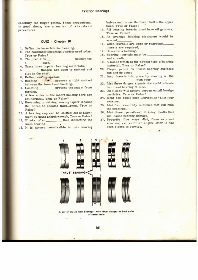
7/26/2019 Auto Service and Repair - Martin W. Stockel
http://slidepdf.com/reader/full/auto-service-and-repair-martin-w-stockel 161/224
carefully
for f inger
prints. These
precautions,
in
good
shops,
are a
mat ter of
standard
procedures.
OU¡Z
-
ChoPter
0
1. Define the term friction bearing.
2.
The
castbabbitt
bearing
is-widelyused
today.
True or
False
?
3.
The
precision-
usuallYhas
a-back.
4. Name three
popular bearing
materials.
5.
flanges
are
used
to control
en d
play
in the
shaft.
6.
Define beafing spread.
?.
Bearing
i : : : ' * '
assures
a
tight contact
between
the
insert
and
housing.
B. Locating-prevent
the
insert
from
turning.
A few nicks in the insert housing bore are
not
harmful.
True
or
False ?
Reversing
or
mixing
bearing
caps
will cause
the bores
to
become
misaligned.
True or
False ?
A bearing cap
can
be shifted
out
of
align-
ment
by using
athick
wrench.
True or
False
?
Blocks often-thus
distorting
th e
main
bearing
-
It is always
permissible
to
mix
bearing
halves
and to use
the lower
halfinthe upper
bore.
True
or
False ?
14.
All bearing
inserts
must have oil
grooves.
True
or
False ?
15.
An
average
bear ing c learanee
would 'be
around-.
When
journals
are
worn or
inserts are required.
Describe a
bushing.
reground,-
Bearing
journals
must be
and smooth
A micro finish
is the newest
type of
bearing
material.
True or
False ?
Finger
prints
on
insert bearing
surfaces
can and-do
cause_.
Snap
inserts
into
place
by shoving
on
the
with
your_.
List three
danger signals
thatcouldindicate
imminent
bearing
failure.
Oil f i l ters
wil l
always
screen
outallforeign
part ic les. True or False?
What
ean cause
poor
lubrication?
List
four
reasons.
List
four
assembly
mistakes
that
wil l ruin
the
bear ings.
List
three
operational
(driving)
faults that
wil l
cause
bearing
dainage.
Describe five
ways dirt,
from external
sources, can
enter
an engine
after
i t
ha s
been
placed in
service.
:r
o
10.
11
t2.
13.
Frict ion
Beorings
16.
17.
18.
19.
20.
2t.
,2
23.
24 .
25.
26.
27.
THRUST
A set
of engine
moin 6eoríngs.
Nofe
fá¡ust flanges
on 6otá sides
cenler moin.
'ññ
ffif
ffi
u&
ffi
W
4
;ñ
ffi
ffi
2
FT
W
n
¿
BEARING
ffi
w
t6 l
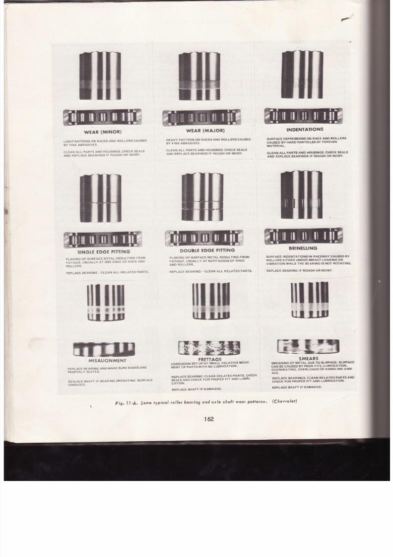
7/26/2019 Auto Service and Repair - Martin W. Stockel
http://slidepdf.com/reader/full/auto-service-and-repair-martin-w-stockel 162/224
wrAR
{$INOR}
L¡6HT
PAIT:EN ÓN
¡:AüES
AN'}
RüLLTFS
CAUS€D
SY
TINE AARASIV€S,
€L€A¡
ALL
PAR:S AI T}
HO|.JSINES'
HECK
SEALS
,{NO
R€flAcÉ
Bea¡¡ l f {es
lF R$usl"l0R
N0lsY.
IIH€IÉ
TDGF
P¡T¡ING
FLAK¡ÑG
üÉ SURFACE
MÉTAL
NÉSUI"I¡NG
FAOM
rATl*{JE. {JSUALLYA CÑT EO€É 8F RACEAN D
ñ{}LLE*S.
ñ€PLACI
B€ARI¡}E
'
CLÉ.q¡}
LL
RELATSD
FARTS
,ti$sAusN*1É¡¡T
¿:IÉFLAC€
€AF NG
AND
TiA'{S
S$RE
RACÉS
AR€
Í*üFisLY
igATe0.
RFPLACI
S}14É¡
IF A€AR }¡G
OPqRAIINC
SURÍACE
G¡IMA*'I}.
wrAn
{üAJoR}
H€AVY
PATf€RN ON
ñAC¡3
ANO ñOLLERS
CAUSE'
AY
FI'$EABRAS¡VES.
CL€AN
AL
PAFTS AND
HOUS'NGS.CH€CT
g€AL$
ANO R€PLACE
€ARINCS
F ROU6H OA NO$Y.
DOUBLE
EDGI
PIÍTINS
FIAXING
OF SURSACE
M€TAL
R€SULfING
FROM
fATIGUÉ. USUALLYA1 BOÍH EDGESOF 8AC€
AND
ROLLERS.
REPLACE
T.A*ING
'
CLEAN
ALL
RÉLATEO
PAFTS'
FRETTAGg
:,?i?**
*
#i.?",tr1"*s5l+üX:
""
REPTACÉ
EARING.
CLEAN
RILAf
ED
PAqTS'
CHECX
slais
Áro
csrcx
FOF
PRopER
l l AND
LUBRI
cAlroN,
R€FLACE
S}IAFf
IF OAMA6ED.
€'
INOINTATIONI
SUEFACE O€PR€SSIOI{$OftI
ñACE
A|\|Ó
NOLLEFS
SAUSÉD
AY
HAi'
PASTiTL€S OF
FOg€ICi¡
iñAT€R
IJIL.
CL€AN
ALL
FAfiTS AIi¡D
I{OU9II{G',
CHICK
SSALS
anto RÉaLA6e
gsaRl¡¡es
lF RcusH
oR
nrolsY.
8nr¡{ELuNc
SURFAC:
iNOEN}ATIüNS IN NAC€IYAY
CII ,SE BY
NOLL€RS
EIÍHER
UND€R IMFAEf
LOADINC OR
VISR¡. ' ION
WHILE TH€ BEARINE S NOf ROfA}ING.
FEPLACT
AEANING
F ROUGFOA
NOISY.
ril$é x$$e
$$$$
tfi$$
tll
ffi
' *
*
**4
q¿üsIs
tl*
**
¿ü
i-B
rÉg&$*w
GG iN
5MÉARS
stáEARlNe
oi
MFIAL
DUE
fo
sLlpP^GE.
SLIPPAGE
CAN
AÉ CAUSED
gY
POOR FITS.
L{JBRICATION,
OVERHÉATING.
OVTRLOAOS
OR
HANNLIN6
OAM.
AG€.
RTPLACE
BEARINGS,
LEAN
RELATEO
PARIS
AN D
.}IECK
FOR
PRO¡ER
F¡T
AND LüARTEATIOII'
REPLAC€
SIAFT
IF DAMAG€D.
F¡g.
1i-A.
Jome
fypicol
rol ler
beoring
ond oxle
shoÍt
weo¡
Polterns'
(Chevrolet)
162
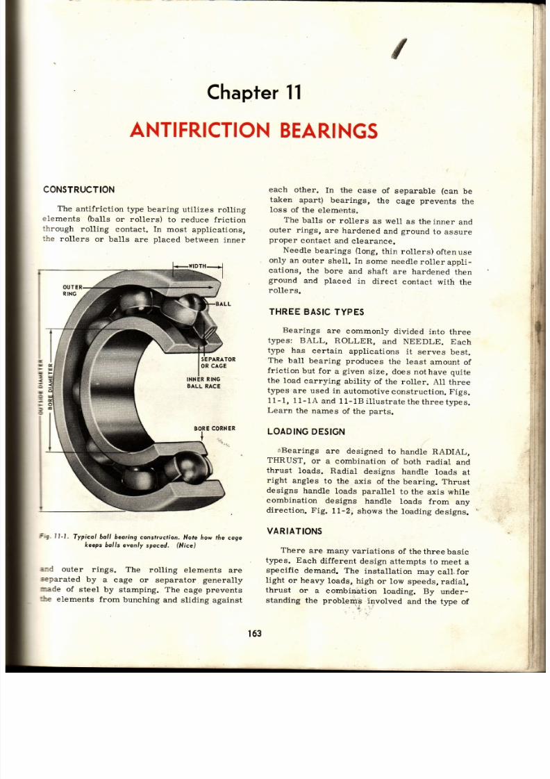
7/26/2019 Auto Service and Repair - Martin W. Stockel
http://slidepdf.com/reader/full/auto-service-and-repair-martin-w-stockel 163/224
ANTIFRICTIONEARINGS
CONSTRUCTION
The
antifr ict ion
type bearing
uti l izes
roll ing
elements
(ba1ls
or rollers)
to reduce
frict ion
:hrough
roll ing
contact.
In
most
applicat ions,
:he
rollers
or balls
are
placed
between
inner
Fi'g.11-1.
Typicol bol l
beoring
construction.
Note how the
coge
keeps 6olls
even/y
spoced.
fNíce)
s¡d
outer
rings. The
roll ing elements
are
separated
by
a cage or
separator
generally
r¡ade
of
steel
by
stamping. The
cage
prevents
túe
elements
from
bunching
and sliding
against
each
other.
In
the
case
of separable
(can
taken
apart)
bearings,
the
cage
prevents
loss
of the
elements.
The
balls
or rollers
as well
as the
inner
an d
outer
rings,
are
hardened
and
ground
to
assure
proper
contact
and
clearance.
Needle
bearings
(long,
thin
rollers)
oftenuse
only
an
outer
shell. In
some
needle
roller appli-
cat ions,
the
bore
and
shaft
are hardened
then
ground
and
pLaced
in
direct
contact with
th e
rol lers.
THREE
BASIC
YPES
Bearings
are
commonly
divided
into
three
types: BALL,
ROLLER,
and NEEDLE.
Each
t¡pe has
certain
applicat ions
it
serves
best.
The
ball
bearing produces
the
least
amount
of
fr ict ion
but for
a
given
size,
does
nothave quite
the load
carrying
abil ity
of the
roller.
Al1
three
type.s
are used
in
automotive
construct ion.
Figs.
11-1, 1 1-1A and 1 1-18 i l lust rate the three tJpes.
Learn
the
names
of
the
parts.
LOADING
ESIGN
{f ,Bearings
are designed
to
handle
RADIAL,
THRUST,
or
a
combination
of both
radial
an d
thrust
loads.
Radial
designs
handle
loads
at
right
angles
to
the
axis
of the
bearing.
Thrust
designs
handle
loads parallel
to the
axis while
combination
designs
handle
loads
from
an y
direct ion. Fig.
11-2,
shows
the
loading
designs.
VARIATIONS
There
are
many
variat ions
of thethreebasic
t¡pes.
Each
dif ferent
design
attempts
f.o
meet
a
specif ic
demand. The
installat ion
may
call-for
l ight
or heavy
loads,
high
or low
speeds,
radial,
thrust
or
a
combination
loading.
By
under-
standing
the proble.mÉ
involved
and the
type
of
Chapter
11
be
the
T
I
I
3
l
tó3

7/26/2019 Auto Service and Repair - Martin W. Stockel
http://slidepdf.com/reader/full/auto-service-and-repair-martin-w-stockel 164/224
Auto
Service
ond
RePoir
Fig.
11-2.
Loodíng
esigns.
A-Rodiol '
B'Thrust '
C-Combinot ion
'rodíal
ond
f i rusl .
Arrows
in
color
indicote
direc' ion
oÍ lood'
-l
*'oin
ts
l¡J
F
UI
=
6
u
6
F
3
o
fnr,*,,o
1r
O.D.
CORNER
RO LER
' \ L -BORE
CORNER
LOAD
ER5
SEPARATOR
OUTSI
E
DIAMETER
l i_
I
ro.t
I
Fío. l l ' lA. Rol ler 6eor ing' Thís port ículor bear ing
topered
ol ler
desígn'
The
oute¡
r ing
is seporate
I-
LENGTH-{
1t-3. Stroightollerbeoríng' esigned
o¡
rodiol
ood
onlv
(AFBMA)
SPH
RI
CA L
ROLLER
l1-4,
Spher íco l
ro l ler
beoring'
Nofe "6o¡¡e l "
shope
o(
ro l lers
(SKF)
utí l zes
(SKFJ
th e
F s'
RETAI
LI P
ROLLE
Fio,
l l -18.
Needfe
6eor ing
ln
this
beoríng
the
rol lers
operole
'"r t t i , r t r ' r í " . r i " t
t ¡ " l l
.oní
ín
di '" t '
conloci
wi lh
o
ho¡dened
nd
oround
hol tsur foce'
(Anl i -F¡ ícl ion
Beoríng
Mfrs'
Assn'
AFBMA)
u
F
ul
=
l¡t
E
o
o
F
l
z
u¡
F
u
o
o
OUTSIDE
164
F
s'

7/26/2019 Auto Service and Repair - Martin W. Stockel
http://slidepdf.com/reader/full/auto-service-and-repair-martin-w-stockel 165/224
i -- l
l l
il
l l
bear ing
best
sui ted, the mechanic wi l l
be
great-
Iy
aided in
al l bear ing work.
Some
of
the
more
common
variations are the
stra ight
rol ler ,
spher ical
ro l ler ,
tapered rol ler ,
deep groove
ba11,
angular
contact ba11, multiple
row,
sel f-a l igning,
etc .
STRAIGHT
ROLLER
The
straight
rol ler is
designed
to
handle
aeavy RADIAL
loads.
In most
designs i t wi l l
: :andle
l i t t le
or
no thrust,
Fig.
11-3.
SPHERICAL
ROLLER
The
rol lers in
th is bear ing
are of curved or
--:herical
shape.
It
wil l handle
HEAVY
radial
lcads
and
MODERATE
thrust 1oads.
I t is
sel f-
= l igning
( to
a degree) ,
Fig.
11-4.
TAP.ERED
OLLER
The
tapered rol ler
is
the
mostwidelyusedof
.he
rol ler bear ings as i t
wi l l
carry
bothHEAVY
:hrust
and radial loads.
The
apex
of the angles
icrmed
by both the ro l lers and
raceways,
i f
:x tended, would meet
on a common axis .
This
a11ows the rol ler
to
fo l low
the
taperedraceways
with no bind
or sk iddlng. Common
pract ice
is
to
secure the
rol lers to
the
cone
with
asteel cage.
The
cone raceway is indented
thus forming
a
l ip that
keeps the rol lers
centered. The
cup
is
then
separable,
Figs.
11-14, and 11-5.
DEEP
GROOVE
ALL
The
deep
groove
bal l bear ing
wi l l handle
HEAVY
radial
and
MODERATE
thrust
loads.
Neither
the inner
or
orr ler r ino. iq
oparable,
Fig.
1
1-
6.
ANGULAR
CONTACT
BALL
This
bal l bear ing wi l l handle both HEAVY
thrust
and radial loads.
The
bal ls
are contained
within
a
cage,
and both inner
and outer r ings
ar e
separable,
Fig.
11-7.
MULTIPLE
ROWBEARING
Bear ings
can employ two or more rows of
bal1s or ro l lers
so that
heavier
loads, both
r :d i¡ l erd ihrnsf onn
lre c :r r ied Thev
can
also
be designed to
prov ide
for
thrust loads inBOTH
direct ions, Fig.
11-8.
INNERRING
OR
CUP RACEWAY
ROLLERS
Fig, l1-5. fopered
rol ler beoring porls.
Once ossembled, this
porticulor
beoring wíl l
hove o seporoble
outer
r ing
but
the
rol lers, coge ond inner ríng wi l l be one
unit.
Ant if r ict ion Beor ings
'il
\
OUTERRING
OR
CAGE
ORSEPARATOR
165
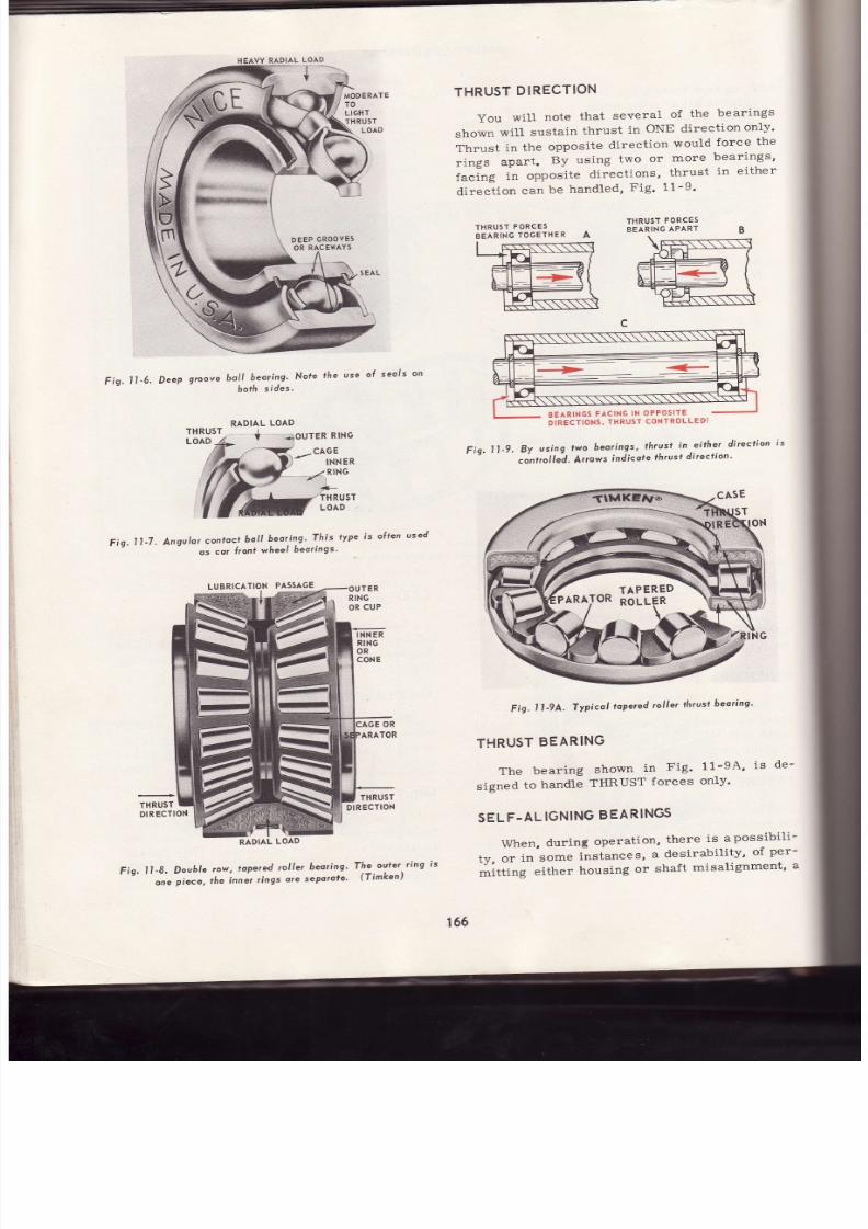
7/26/2019 Auto Service and Repair - Martin W. Stockel
http://slidepdf.com/reader/full/auto-service-and-repair-martin-w-stockel 166/224
VY
RADIAL
LOAD
MODERATE
TO
LIGHT
THRUST
LOAD
DEEP
GROOVES
OR
RACEI{AYS
boll
beoríng,
Nole
the
use
of
seols
on
6ofá
sídes.
THRUST
DIRECTION
You
wi l l
note
that
several
of
the
bearings
shown
will
sustain
thrust
in
ONE direction
on1-y'
Thrust
in
the
opposite
direction
would
force
the
rings
apart.
By using
two
or
more
bearings'
facing
in
opposite
directions,
thrust
in
either
direc i ion can be handled, Fig ' 11-9 '
THRUsT
FORCES
BEARING
TOGETHER
THRUST
FORCES
BEARING
APART
Fig.11'6-
DeeP
groove
THRUST
LOAD
ER
RING
-to,o*tnr*
--t'/Rlno
Fiq.
11-7.
Angulor
contoct
bol l
bearing'
This
type
s
often
used
os
cor
l ront
wheel
beorings'
Fiq,
1l -9.
By
using
lwo
bearings'
lh¡ust
in
.ei the.r
di ¡ecl ion
.on¡otted.
Ar¡ows
indicole
lhrusf
di rectíon'
Fig.
l1 '9A.
Typicol
lopered
rol ler
thrus
beoring'
LUBRICA
PASSAGE
OUTER
RING
OR
CU P
INN
ER
RING
OR
CONE
RADIAL
OAD
Fig'
1l -8.
Double
ow,
topered
ol ler
beoring'
one
piece,
the
inner
r ings
ore
seporote'
THRUST
EARING
The bear ing shown in Fig ' 11-9A'
is
de-
signed
to
handle
THRUST
forces
only'
SEL
F.AL
IGNING
BEARINGS
When,
during
operation,
there
is
apossibil i-
ty,
or
in
some
instances,
a
desirabil i ty '
of
per-
áittirrg
either
housing
or
shaft
misalignment'
a
fHRUST
DI
RECTION
OR
ARATOR
The
ouler
r ing
is
(Timken)
BEARINGS
ACING
N
OPPOsITE
DIRECTIONS.
HRUST
CONTROLLEDI
CASE
166

7/26/2019 Auto Service and Repair - Martin W. Stockel
http://slidepdf.com/reader/full/auto-service-and-repair-martin-w-stockel 167/224
self-aligning
bearing is used.
This
bearing
will
11ow
a degree
of
t i l t without
distort ingthebear-
:ng
elements. Both
internal and
external self-
aligning
bearings are
shown
in
Fig.
11-10.
OUTER
RING
INTE
RNAL
EXTERNAL
Fig. l I-10.
lnte,rnal nd exlernolselÍ-o l igning beorings.Nofe how
*e
sÁofi
is
l¡ee to t ip.
The
exfe¡nol design wil l handle heovier
Joods
os
the
boll hos o wider contoct oreo with the
outer
rinq.
tsEARING
DENTIFICATION
All bearings are marked
with
part
number,
lsually
on
the face
of the r ings,
for
ease of
re -
¡l.acement.
I f necessary, replacement bearing
size
can be checked by careful
measuring.
BEARINGSEALS
Bearings
can
be open on both sides or sealed
on one
or both. Sealing on one side
is
often used
:o
help
confi.ne lubricant and topreventthe entry
cf dirt . When both sides are sealed, the bearing
:s
lubricated
during
assembly
and no lubricant
can be
added in the
f ie ld, Fig.
11-11.
REMOVING
EARINGS
Prior
to
pull ingbearings,
clean
the
surround-
:ng
area to
prevent
contamination.
Bearings
are
generally
best removed
with
srechanical
or hydraulic
pushing
or
pull ingtools,
which
exert a heavy and
STEADY
force,
Fig.
11- 12.
In
the absence of such
pullers,
or
in
cases
where
their
use
is impossible or undesired, a
suitable hammer in combination
with soft steel
drif ts,
sleeves and cup drivers,
wil l handle
many
jobs.
Any
attempt
to
pull
or install a
bearing
by
exerting force on
the freg
(not
tight)
ring
is apt
ro
chip
the bal1s or
rollers.
The
ring
itself
eould
crack
and
fly
apart
inadangerousfashion.
NO SEALS
Fig. l IJl . Beoring seo/ conslrucl ion
Fig. lI -12.
Removing
iÍ lerentiol inion
shalt
beoringwith hy-
droulic
puller.
(O.T.C.)
There
are
some
instances,
as
you
will
see later,
that require force
on either the
free
ring or
roll ing elements.
However,
WHENEVER POSSI-
BLE, EXERT THE FORCE ON THE TIGHT
RING
ONLY.
Fig.
11-13, shows both the
r ight and
wrong
way
of applying
pulling
force. Note
that in
A,
the support ing
puller plate
rests
on the
free
PRESSED
Fig.
l l-13.
Pull ing
setups.
A-Vlrong
s force is opplied
hrovgh
lree oule¡
ring ond rolling elements. 8-Correct. Force
is ffirough
tight r ing only.
167
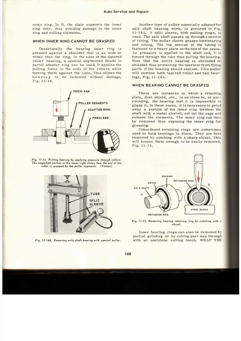
7/26/2019 Auto Service and Repair - Martin W. Stockel
http://slidepdf.com/reader/full/auto-service-and-repair-martin-w-stockel 168/224
Auto Service
qnd
Repqir
outer
r ing.
In B,
the
plate
supports
the inner
ring only, thus avoiding damage to
the
outer
r ing and
roll ing elements.
WHEN
NNER
RING
CANNOT
E GRASPED
Occasionally
the bearing inner r ing
is
pressed against a shoulder that is as wide or
wider
than the r ing.
In the
case of
the tapered
roller bearing,
a special segmented
(made
in
parts)
adapter r ing
ean
be used.
It
applies
the
pull ing
force
to the ends of the rollers
whl1e
forcing
them against the
cone.
This
allows
the
bear ing to be removed
without
damage,
Fig.
11- 14.
PRESS AM
PULLERSEGMENTS
ADAPTOR
ING
PRESS
ED
Fig. 1l -14. Pul l ing bearing by opplying pressure hrough rol lers.
The nognilied
porlion
at lhe lowe¡ rigfit
sñows how lhe e nd o( t he
rol ler is
grosped
by
the
pul ler
segments.
(Tinken)
Another
type of
puller
especially adaptedfor
axle
shaft bearing work, is
pictured
in
Fig
11-144. A
split sleeve, with
pull ing
rings, i*q
used.
The
axle shaft
passes
up throughasectior:
of tubing.
The puller
sleeve
grasps
bothbearing
and
tubing.
The
top
section
of
the
tubing
is
fastened to a heavy
plate
onthe bed
of
the
press.
As pressure is applied to the shaft end, it is
forced
through the tube thus
pull ing
the bearing.
Note that
the entire bearing is
shrouded or
shieLded thus
protecting
the
operator from flying
parts
if the bearing
should explode. This
puller
wi l l
remove both tapered roller
and ball bear-
ings, Fig.
11-14A.
WHEN BEARING
CANNOT
BE
GRASPED
There
are instances in which
a retaining
plate,
dust
shield, etc.,
is
so
close
to,
or sur-
rounding,
the bearing
that it is impossible to
grasp
i t . In
these cases, i t isnecessaryto gr ind
away a
portion
of the inner r ing
(protect
the
shaft with a metal
sleeve),
cut out the cage ani
remove the elements. The
outer
r ing
can then
be removed
thus exposing the inner
ring for
grasping.
Unhardened
retaining r ings
are sometimes
used to hold bearings
in
place. They
are best
removed by notching with
a sharp
chisel.
This
wi l l
loosen them
enough to be
easily
removed,
Fie.
11-15.
RETAINING
RING
Fiq. l l-15. Removíng
eoring.rctoi.ning
ing
by
notching
with
o
Inner
bearing r ings can also
be removed
by
partial
grinding
or by cutting
part
way through
with
an
acetylene cutting
torch. WRAP TIIE
SPLIT
SLEEYE
STEEL BLOCK
Fig.
l l -14A.
Removing
oxle
sho{t
beoring wi th
speciol
pul ler.
168
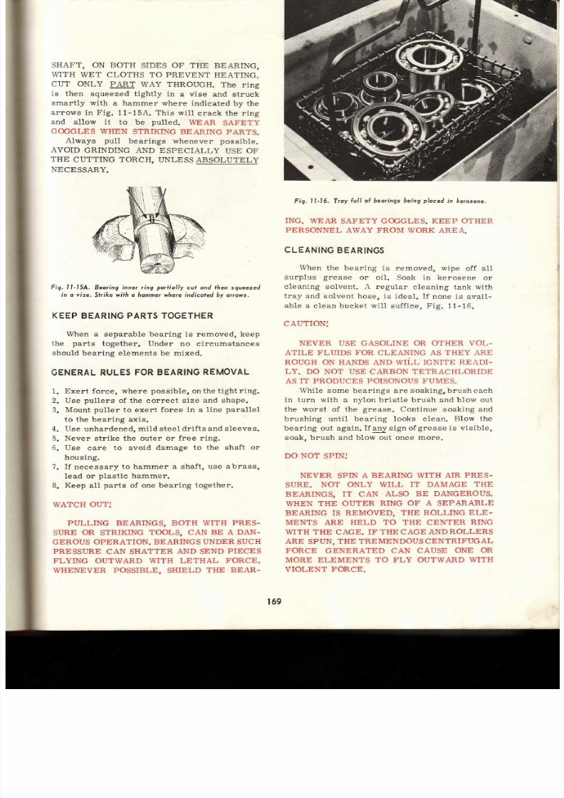
7/26/2019 Auto Service and Repair - Martin W. Stockel
http://slidepdf.com/reader/full/auto-service-and-repair-martin-w-stockel 169/224
SHAFT,
ON
BOTH
SIDES
OF
THE BEARING,
WITH
WET
CLOTHS TO PREVENT
HEATING.
CUT ONLY
PART
WAY
THROUGH.
The ring
is
then
squeezed tightly
in
a vise and struck
smartly with
a
hammer where
indicated
by the
arrows
in Fig.
11-15A. This
wi l l
crack
the
ring
and allow it to be pulled. WEAR SAFETY
GOGGLES
\A/HEN
STRIKING BEARING
PARTS.
Always
pull
bearings whenever possible.
AVOID
GR,INDING
AND ESPECIALLY
USE
OF
THE
CUTTING TORCH, IINLESS
ABSOLUTELY
NECESSARY.
Fig. I l -15A.
Beoring
inner
r ing
port io l ly
cul ond tf ien
sgueezed
in o vise.
Srrike
with a hommerwhere indicoted by orrows.
KEEP
BEARING
ARTS
OGETHER
When
a separable bearing is removed, keep
the parts
together. Under
no circumstances
should
bearing
elements
be mixed.
GENERAL ULES ORBEARING EMOVAL
Exert force, where
possible,
onthe
tight r ing.
Use
pullers
of the correct size
and shape.
Mount
puller
to
exert
force in a l ine
parallel
to the bear ing
axis .
Use
unhardened,
mild steel
drifts and sleeves.
Never
str ike the
outer or
free r ing.
Use care to avoid
damage
to the shaft
or
housing.
I f necessary
to hammer a shaft ,
use abrass,
Iead or
plastic hammer.
Keep
all
parts
of one
bearing
together.
WATCH
OUT:
PULLING BEARINGS, BOTH WITH
PRES-
SURE
OR
STRIKING
TOOLS, CAN BE A
DAN-
GEROUS
OPERATION. BEARINGS UNDER SUCH
PRESSURE
CAN SHATTER
AND
SEND
PIECES
FLYING
OUTWARD WITH
LETHAL
FORCE
WHENEVER POSSIBLE,
SHIELD
TITE BEAR-
F¡g.
II-16. Troy
lul l o l beoringsbeing
ploced
n kerosene.
ING.
WEAF,
SAFETY GOGGLES.
KEEP OTHER
PERSONNEL
AWAY
FROM
WORK AREA.
CLEANING BEARINGS
When
the bearing
is removed,
wipe
off all
surp lus
grease
or oi l .
Soak in kerosene
or
cleaning
solvent. A regular
cleaning tank with
tray
and solvent ho se,
is ideal. If
none is
avail-
able a
clean
bucket wi l l
suf f iee,
Fig.
11-16.
CAUTION:
NEVER
USE GASOLINE
OR OTHER VOL-
ATILE
FLUIDS
FOR
CLEANING AS
THEY ARE
ROUGH
ON HANDS
AND WILL'IG}TITE
READI-
LY. DO NOT USE CARBON TETRACHLORIDE
AS
IT PRODUCES
POISONOUS
FUMES.
While
some bear ings are soaking,brusheach
in turn with
a nyl on bristle brush and blow
ou t
the
worst of the
grease.
Continue soaking
an d
brushing until bearing looks clean.
Blow
th e
bearing out
again.
If
any sign of
grease
is visible,
soak, brush and
blow
out once
more.
DO NOT
SPIN:
NEVER
SPIN
A BEARING WITH
AIR
PRES-
SURE.
NOT ONLY WILL IT
DAMAGE THE
BEARINGS, IT CAN
ALSO BE
DANGEROUS.
WHEN THE OUTER RING OF A SEPARABLE
BEARING IS
REMOVED, THE
ROLLING
ELE.
MENTS
ARE HELD
TO THE
CENTER
RING
WITH THE CAGE.
IF TIIE
CAGE
ANDROLLERS
ARE
SPUN,
THE TREME NDOUS CENTRIFUGAL
FORCE
GENERATED
CAN CAUSE
ONE
OR
MORE ELEMENTS TO FLY OUTWARD
WITH
VIOLENT FORCE.
1
2
,
A
169
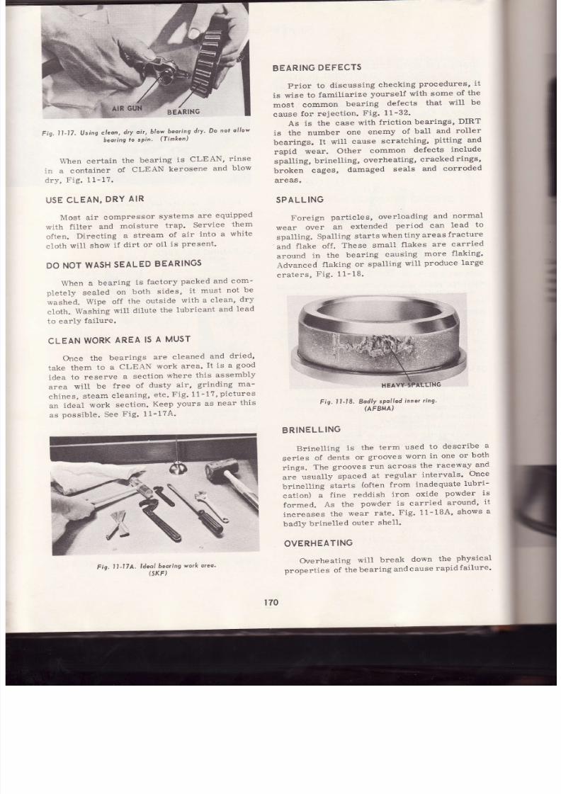
7/26/2019 Auto Service and Repair - Martin W. Stockel
http://slidepdf.com/reader/full/auto-service-and-repair-martin-w-stockel 170/224
,r,:;,rl
\
*;Í3:r,
BEARING
Fig.
l l -17,
Using
leon,
dry
oí r ,
b low
beor ing
ry Do
not
ol low
-
beoríng
o sPin
(Timken)
\ \ -hen certain
the
bear ing
is
CLEAN,
r inse
:l a
container
of
CLtrAN
kerosene
and
blow
ir \ ,
Fig. 1
1-
17 .
USE
CLEAN,
DRY
AIR
Nlost
air
compressor
systems
are
equipped
-, , i th
f i l ter
and
moisture
trap.
Service
them
cften.
Direct ing
a
stream
of
air
into
a
white
c loth wi l l show
lf
dir t
or
oi I
is
present
DONOT
WASH
EALED
EARINGS
When
a
bear ing
is
factory
packed
and
com-
pletely
sealed
on
both
sides,
i t
must
not
be
t ashed.
Wipe
off
the
outs ide
rv i th
a c lean
dry
cloth.
Washing
wi l l
d i lute
the
lubr icant
and
lead
to ear ly
fai lure.
CLEAN
WORK
AREA
IS
A
MUST
Once
the
bear ings
are
cleaned
and
dr ied
take
them
to a
CLEAN
work area.
I t is
a
good
idea
to reserve a sect ion where this assembly
area
wi l l
be
f ree of
dusty
air ,
gr inding
ma -
chines,
steam
cleaning,
etc.
Fig 11-1?
pictures
an
ideal
work
sect ion.
Keep
yours
as
near
this
as
possible. See
Fig. 11-174
1l-17A.
ldeal
beoring
(SKF)
BEARING
DEFECTS
Prior
to
discussing
checking
procedures,
i t
is
wise
to
familiarize
yourself
with
some
of
th e
most
common
bearing
defects
that
wil l
be
cause
for reject ion.
Fig.
t l -32.
As is the case with fr ict ion bearings, DIRT
is
the
number
one
enemy
of
ball
and
roller
bearings.
It
wi l l
cause
scratching,
pit t ing and
rapid
wear.
Other
common
defects
include
spall ing,
brinet l ing,
overheating,
cracked
rings,
broken
cages,
damaged
seals
and
corroded
areas.
SPAL
L ING
Foreign
part ic les,
over loading
and
norrnal
wear
over
an
extended
per iod can
lead
to
spal l ing.
Spal l ing
star ts
whent iny
areas
fracture
and f lake off. These
sma11
f lakes
are
carr ied
around
in
the
bear ing
causing
more
f lak ing
Advanced
flaklng
or
spall ing
wi l l
prodr rce
large
craters,
Fig. 11-18.
Fig.11-18.
Bodly
spolIed
nner
ing
(AFBMA)
BRINELLING
Brinel l ing
is
the
term
used
to
descr ibe
a
ser ies
of
dents
or
grooves
worn
in one
or
both
r ings.
The
grooves
run
across
the
raceway
an d
are
usual ly
spaced
at
regular
intervals
Once
brinell ing
starts
(often
from
inadequate
lubri-
cat ion) a f ine reddish iron
oxide
powder
is
formed.
As
the
powder
is carr ied
around
it
increases
the
wear
rate.
Fig.
11-1BA
shows
a
badly
br inel led
outer
shel l .
OVERHEATING
Overheatlng
will
break
down
the
physical
oropert ies
of
the
bear ing
and
cause
rapid
fai lure
g.
worr(
oleo.
170

7/26/2019 Auto Service and Repair - Martin W. Stockel
http://slidepdf.com/reader/full/auto-service-and-repair-martin-w-stockel 171/224
Fig.
l l -18A.
B¡ inel led
eedle
eor inq
hel l_
-ack
of
lubr icat ion,
improper
lubr icat ion,
poor
=djustment,
etc .,
are
the
pr inc ipal
causes. The
:ear ing
r ings
and
rol l ing
elements
which
have
:een
overheated,
wi l l
have
a blue
or brownish-
: iue
discolorat ion,
Fie.
11-1g.
Fig.
l l -19.
Overheoted
beoring
-
note
disco/o¡orion.
CRACKED
RINGS
One
or both
r ings
may
be
cracked.
Improper
removal
or
assembly
techniques
and
wrongbore
or
shaft
s lze
are
common
causes, Fig.
11-20.
BROKEN
RDENTED
AGE
Improper
removal
and
assembly
procedures
wi l l
often
resul t
in
a dented
or broken
cage.
Pieces
of
dir t
and
metal
chips
wi l l
a lso
cause
cage
breakage,
Fig.
I I-21.
Fig .
ll
_21
gro/<en
coge.
DENTED
SHIELDS
As
with
a broken
cage,
careless
assembly
often produces
dented
shields.
This
could
also
damage
the
eage
as
wel l
as
cause
binding and
lubr icant
loss, Fig.
IL-22.
Fig.
l l -22.
Bodly
dented
6eoring
shield or
seol
New
Deporture)
Ant if r ict ion
Beor ings
BRINELL
Fig.
l l -20.
Crocked
nne¡
rtno.
171
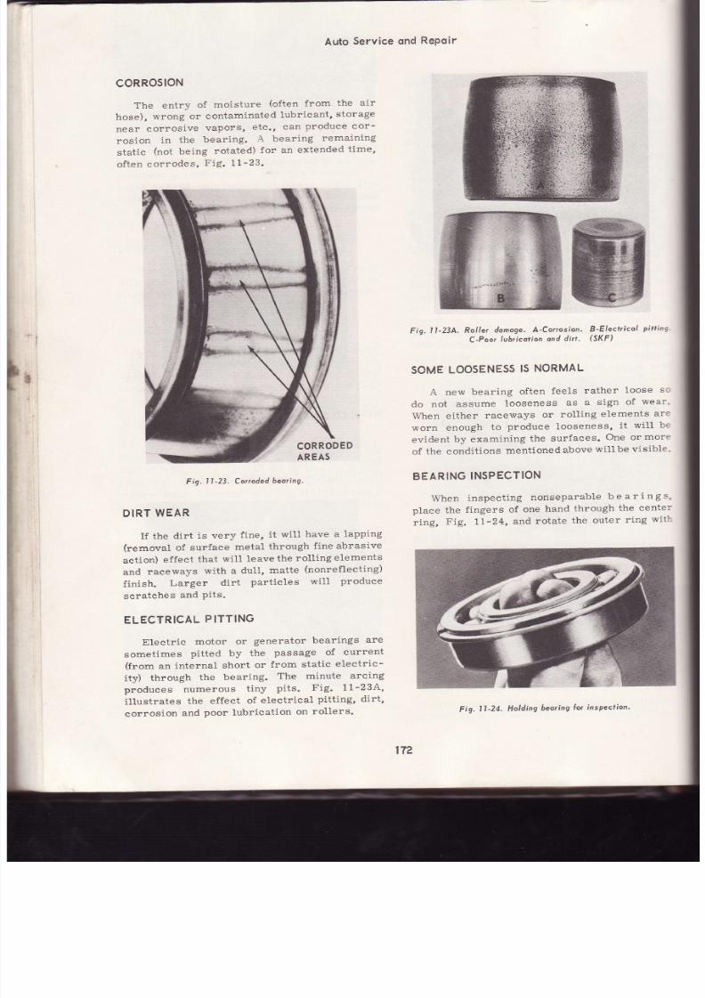
7/26/2019 Auto Service and Repair - Martin W. Stockel
http://slidepdf.com/reader/full/auto-service-and-repair-martin-w-stockel 172/224
¡
Auto
Service
ond
RePoir
coRRosloN
The entry
of
moisture
(often
from
the air
hose),
wrong
or
contaminated
lubr icant,
s torage
near
corros ive
vapors,
etc .,
can
produce cor-
ros ion
in the
bear ing.
A
bear ing
remaining
static
(not
being
rotated)
for an
extended
time,
often
corrodes,
Fig. t t-23.
F
g.
1
-2j .
Corroded
eoring'
DIRT
WEAR
I f the
dirt
is very
fine,
it
wil l have
a
lapping
(removal
of
surface
metal
through
fine abrasive
action)
effect
that
wil l
leave
the
roll ing
elements
and
raceways
with a
dull,
matte
(nonrefleeting)
finish.
Larger
dirt
particles
wil l
produce
scratches
and
Pits .
ELECTRICAL
PITTING
Electr ic
motor
or
generator
bearings
are
sometimes
pitted by
the
passage
of
current
(from
an
internal
short
or
from
static
electr ic-
ity)
through
the
bearing.
The
minute
arcing
produces
numerous
t iny
pi ts .
Fig. 11-234,
i l lustrates
the
effect
of
electr ical
p i t t ing,
dirt,
corrosion
and
poor lubrication
on
rollers.
Fig.
1l -23A.
Rol ler
donoge.
A'Cor¡osion'
B-Electrícol
pi tt ing
C-Poor
ubricotion
ond
dirt '
(Sl (F)
SOME
LOOSENESS
S
NORMAL
A
new
bear ing
often
feels
rather
loose
sc
do
not
assume
looseness
as
a
sign
of
wear '
When
either
raceways
or
roll ing
elements
ar e
worn
enough
to
produce
looseness,
i t
wi l l be
evident
by examining
the surfaces.
One or
more
of
the conditions
mentioned
above
wil lbe
visible'
BEARING
NSPECTION
When
inspect ing
nonseparable
be
ar ings,
place the
fingers
of
one
hand
through
the
center'
r ing,
Fig. 1 l-24,
and
rotate
the outer
r ing
wit l
CORRODED
AREAS
17?
F¡g.11-24.
Holding
beoring
or
inspectíon'

7/26/2019 Auto Service and Repair - Martin W. Stockel
http://slidepdf.com/reader/full/auto-service-and-repair-martin-w-stockel 173/224
Ant if r ict ion Beor ings
-he
other, The
bearing
should
revolve
smoothly
¡;-th
no
catching
(stopping
momentari ly)
or
:cughness.
I f
e i ther
condit ion
is
present,
r inse
-rd
blow
dry
again. If
the
symptoms
sti l l
per-
=:s t,
d iscard
the bear ing.
Also
check for
s igns
: i
overheating
and wear
on
the
outer
surfaces
: l
both
rings. A
bearing
that
has
been loose in
::re bore, or on the shaft, wil l have highly
-
c l ished
areas
showing.
For
separable
bearings,
carefullyinspect
the
::ceways
and rol l ing
elements. They
should be
::solutely
smooth
and free
ofheat
discoloration.
-:-spect
EACH
ball or roller,
as
quite
often
only
:1e
or
two may
be damaged.
When
satisfied
as
,o
condition,
place
the
elements
together. While
Jrreing
them
together,
rotate
the bearing. The
-r?eration
should be
smooth.
When
revolving
bearings,
do
so a number
of
rmes,
as
a single
damaged
ball
or roller
ma y
:ct
catchrr
the
first few
times
around.
When
:hecking
thrust
bearíngs,
place
one side on a
.clid
surface.
Press
down
on
the
other with
th e
:-ee1
of
your
hand
and
while
maintaining pres-
.. :re,
rotate.
KEEP
HANDS
CLEAN,
DRY AND
' ' ' {Y
FROM
RACEWAYS
AND ROLLING
a-
EMENTS.
See
Fis.
t t-24,
DO
NOTSAVE
ONE
PART
I f
any
part,
outer
or
inner r ing
or roll ing
:-ements
are damaged, d iscard
the ENTIRE
iear ing.
Never
replace
a
part
of a bear ing.
Before
discarding,
write
down the
part
:-:lmber.
It
is
a
good
idea to wire the
parts
to-
:ether and keep for
comparison
with
the re-
:Lacement
bear ing. Mark
as DEFECTIVE.
BEARING
UBRICATION
I f
the bearing wil l
be
placed
into
service at
:nce,
it
may be
packed
with
the
proper grease
rr
it
may be
oiled, depending
upon the need.
Cover
with
a clean
cloth
unti l
ready to install.
-l
it
wil l
be stored for
a
few
days,
coat
with
oi l
:nd place
in
a clean
box or
container.
At
an y
:ate,
IMMEDIATELY
FOLLOWING INSPEC-
TION,
COAT
WITH THE
DESIRED LUBRICANT
TO PREVENT
THE
FORMATION
OF
RUST
>ee
Fig.
Ll-25.
I f
the bearing wil l
be
stored for an
extended
reriod,
coat
with
light
grease,
wrap in
oilproof
_¡aper
and
place
in
a clean box.
Be
sure
to
:dentify
the
bearings to
prevent
opening a number
of
them
when
looking for
a specific
one at some
Fig. I I
-25.
Beorings leoned,
oíled
ond
ploced
in
protecfive
contdine¡.
future
date.
When
coating bearings
for
storage,
rotate
toinsure proper
penetration
and coverage,
Fig.11-26.
PACKING
ITH
GREASE
When
a bear ing
cal1s
for
grease
(speci f ic
recommendations
for
each
type wil l
be
given
in
the sect ion to which they perta in) , use abear ing
Fig. l l -26.
Beorings
greosed
ond wropped
lor extended
storoge.
packer.
If
no
packer
is
available, place
a
gob
of
grease
(hands
clean and dry)
on
the
palm
of
one hand.
With
the
other
press
the
edge of the
bear ing
into
the
grease
(near
the
edge).
Repeat
this
unti l
grease
flows
out
the top.
Move
around
to different
sections
unti l
the bearing is fully
packed.
Separable
rings
should be
coated
also.
See
Fig.
LL-27.
PROTECT UBRICANTS
All
grease
and oil in
the
shop should
be kept
in
clean
containers
and
kepttightlyeovered
when
not in use. When
opening, wipe
dirt off l i .d
an d
avoid dusty
areas. An open
can of
grease
near
a
grinder,
cutting torch, etc., is
anopeninvitation
to disaster .
173
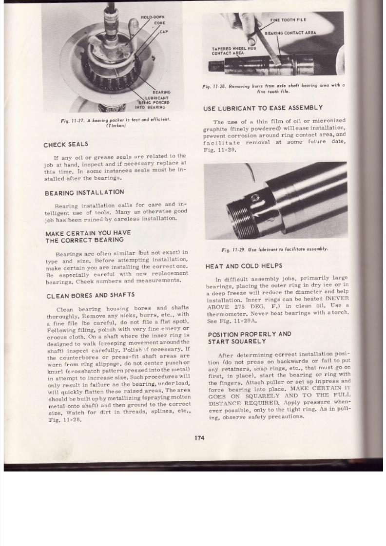
7/26/2019 Auto Service and Repair - Martin W. Stockel
http://slidepdf.com/reader/full/auto-service-and-repair-martin-w-stockel 174/224
BEARING
ONTACT
RE A
TAPERED
HEEL
UB
I
Fig.
11-28. Removing
burrs
hom
oxle
sholt
beoring
oreo
wilh
o
l ine ¡ooth f i le -
USE
UBRICANT
O
EASE
ASSEMBLY
The use
of
a
thin
f i lm
of oil
or
micronized
graphite
(f inely
powdered)
wil l
ease
installat ion,
prevent
corrosion
around
ring contact
area,
and
faci l i tate
removal
at
some
future
date,
Fig. 1
1-2
9.
Fig.
t l
'29.
lJse
lubricon¡
o loci l i¡ote
ossem6ly '
HEAT
AND
COLD
HELPS
In dif f icult
assembly
jobs, primarily
large
bearings,
placing
the
outer
ring
in
dry
ice
or
in
a
deep
freeze
will
reduce
the
diameter
and
help
installat ion.
Inner
rings
can
be
heated
(NEVER
ABOVE
275
DEG.
F.)
in clean
oil.
Use
a
thermometer.
Never
heat
bearings
with atorch'
See
Fig. 11-294.
POSITION
ROPERLY
AND
START
SOUARELY
After
determlning
correct
installat ion
posi-
t ion
(do
not
press on
backwards
or
fail
to
pu t
any
retainers,
snap
rings,
etc., that must go on
first,
in
place),
start
the
bearing
or
ring
with
the
f ingers.
Attach
puller
or
set
up
inpress
an d
lorce
bearing
into
place.
MAKE
CERTAIN
IT
GOES
ON SQUARELY
AND
TO
THE
FULL
DISTANCE
REQUIRED.
App1y
pressure
when-
ever
possible,
only
to
the
t ight
r ing'
As
in
puIl-
ing,
observe
safetY
Precautions.
LUBRICANT
FORCED
II¡:f
BEARING
Fig.
It '27.
A
beoringrPocker
r is
fust
ond
eÍl ic ient '
CHECK
EALS
If
any
oil
or
grease
seals
are
related
to
th e
job
at
hand,
inspect
and
if
necessary
replace
at
thís
t ime.
In
some
instances
seals
must
be
in-
stal led
af ter
the
bear ings.
BEARING
NSTALLATION
Bearing
installat ion
calls
for care
and
in-
tell igent
use
of
tools.
Many
an
otherwise
good
job
has
been
ruined
by
careless
instal lat ion'
MAKE
CERTAIN
OU
HAVE
THE
CORRECT
EARING
Bearings
are
often
similar
(but
not
exact)
in
type
and
size.
Before
attempting
installat ion'
make
certain
you are
instal l ing
the
correctone'
Be especial ly careful with new replacement
bear ings.
Check
numbers
and
measurements '
CLEAN
BORES
AND
SHAFTS
Clean
bear ing
housing
bores
and
shafts
thoroughly.
Remove
any
nicks,
burrs,
etc',
with
a
f ine
f i le
(be
careful,
do
not
f i le
a
f lat
spot) '
Following
fi l ing,
polish
with
very
f ine
emery
or
crocus
cloth.
On a
shaft
where
the
inner
ring
is
designed
to
walk
(creeping
movement
aroundthe
shaft)
inspect
carefully.
Polish
i f
necessary'
If
the counterbores
or
press-f it
shaft
areas
ar e
worn from ring sl ippage, do not center
punchor
knur l
(crosshatch
pat ternpressed
intothe
metal)
in
attempt
to
increase
size.
Suchprocedures
wi l l
only
resul t
in
fai lure
as
the
bear ing,under load'
wil l
quickly
f latten
these
raised
areas'
The area
should
be
built
up
by
metallízing
(spraying
molten
metal
onto
shaft)
and
then
ground
to
the
correct
size.
Watch
for
dir t
in
threads,
spl ines '
etc"
Fie.
11-28.
174

7/26/2019 Auto Service and Repair - Martin W. Stockel
http://slidepdf.com/reader/full/auto-service-and-repair-martin-w-stockel 175/224
-
Ant if r ict ion Beor ings
SIMPLE
TOOLSWILL
OFTEN SUFFICE
If regular
pressing
tools are not available,
simple driving tools
wil l handle many
jobs
in
a
satisfactory manner.
Make
sure
they are
clean.
Str ike the
tight
r ing
on1y.
Use
soft steel
tools.
Brass
tools
tend
to
mushroom and chip
thus
contaminating the bear ings.
Fig.
l1-29A.
Heal ing o beoring n oi l . Hook keeps
beoring rom
touching
boltom of confoiner .
R,iS.
l l -30.
Beoring
instol lot ion I inrs.
A-Do
nol
str ike
oeoring
*i th
o hammer.
B-Do
nol use wide
puncñes
on
beorings.
C-Do
apply
ürce lo
t ight r ing
(l )
and hove cleo¡once
(2)
hr shof¡. D-Use
ariver
wi th
smoolh,sguore
cuf ends
ho¡
srr ike
ight r ing, E-Cleon
eoríng
ring recess
5)
and lorce ing to ful l deplh. F-Block
ploced
ffi
open
pipe
driver ollows driving
force to be centralized.
Use
protective
vise
jow
cove¡s
(6). (AFBMA)
SHAFT
ANDHOUSING
ORES
MUST
BE
TRUE
A
sprung shaft
or bent
housing wi l lcausethe
bearing to operate in
a
distorted
position,
thus
greatly
shortening
i ts l i fe.
For
those
jobs
in
which the bearing failed in
a
short time, despite
proper installation, lubrication and adjustment,
always check shaft and
housing
for
any
warpage
or other
misalignment.
BEARING
ADJUSTMENT
Some bear ings
require adjustment after
in-
stallation.
Proper
adjustment
depends on the
appl icat ion. Some require a speci f ic
amount of
free
play
and others require
preloading
(plac ing
the
bear ing under
pressure
so that
when
a
dr iv ing
force is
appl ied
to the
parts ,
they
wi l l
not
spring out of
alignment).
As the various
serv ice operat ions are descr ibed through the
book,
general
adjustment
recommendations
wi l l
be
given.
GENERAL
RULES
FOR
BEARING NSTALLATION
1. Clean al l contact
sur faces
and remove burrs ,
2
h
nicks,
etc .
Instal l par ts
that
precede
bear ing.
Lubricate
for
easy
installation.
I f heat
is required,
donotexceed2T5 deg.
tr .
Start bearing squarely.
Align tools so that bearing wil l be forced
nn
qnrrara lr¡
7.
For
dr iv ing tools , use soft s teel .
B. When
possible,
avoid
applying
pressure
through bal ls
or
rol lers .
9.
I f
av ise
is needed, use
protect ive
jaw
covers.
10.
Driving tools must
have
smooth, square
cut ends.
11.
Do
not
mar
shaft or
bore sur faces.
12.
Use safety
precautions.
13.
Press
on
the fu l l d is tance required.
Fig.
11-30,
i l lustrates a
few
dors and
donrts
regarding
bear ing assembly.
SUMMARY
Bear ings
can
be div ided
into
three basic
types; the
BALL, ROLLER,
and
NEEDLE. The
ball
and roller bearing usually consists
of an
inner
and outer
r ing with the roll ing elements
placed
between them and
posi t ioned with
a cage
or separator .
The
needle
bear ing
can
use an
t75

7/26/2019 Auto Service and Repair - Martin W. Stockel
http://slidepdf.com/reader/full/auto-service-and-repair-martin-w-stockel 176/224
Auto
Service
ond
RePoir
outer
shell,
or
can
be
placed
in
direct
contact
*irt
"
hardened
and
ground
bore
and
shaft'
Bear ings
are
designed
to
carry
ei ther
"ttJghi
thrrist,
radial
or
combination
loads'
The
straight,
spherical
and
tapered
roller'
the deep groove
bal1,
angular
contact
ball'
and
"áit-.rii"I"g
of
both
types'
are
the
common
variations.
Bearings
are
marked
with
part
number'
Bearings
are
often
sealed
on
one
or
both
sides.
Uerr-er
wash
bearings
sealed
onboth
sides'
Hydraulic,
mechanical
puller
or
striking
tools
can
be
used
to
remove
bearings'
All
must
be
used
with
care'
If
available'
hydraulic
and
mechanical
pullers
are
recommended'
PuIl
bearings,
whenever
possible'bythe
ring
that
is
tight.
Speeial
tools
are
available
fo r
p"irt"e
by-exerting
pressure-
lhr?ue:
the
balls
it
toir""".
Avoid
the
use
of
heat'
Do
not
mar
bore
or
shaft
surfaces'
Whenbearing is removed'
i f
separable,
keep
a1l
parts
together'
Clean
bearings
in
kerosene'
Blow
dry'
r inse
in
fresh
kerosene
and
blow
dry
again'
Do
no t
spin
the
bearing.
Air
should
be
clean
and
dry'
Working
in
a
clean
area'
inspect
bearing'
I f
satisfac-tory,
oil
or
pack
with
grease
at
once'
Keep
covered
unti l
ready
to
install '
Rejected
bearings
may
be
kept
for
size
comparison
with
replaclments
but
MARK
them
as
REJECTS'
'S"t"t"ted,
pitted,
spalled'
brinelled'
cor-
roded,
cracked,
and
overheated
bearings'
plus
it.""
with
damaged
cages
or
dented
shields
MUST be REJECfBD. Never replace onepartof
a
bearing.
-
f.ep"atl
lubricants
covered
when
not
in
use'
A
bearing
packer
is
handy
for
lubing
with
grease.
Replace
defective
grease
or
oil
seals'
Clean
bore
and
shaft,
remove
burrs
and
install
any
parts
that
must
Precede
bearing'
Lubr icatebear ingseatarea'posi t ionbear ing
.
correctly
and
start
Uyttana'
PulI'
press'
or
drive
bearing
fulIy
into
pi"ce
kt"ping
square
at
al l
t imes.
Do.not
aamage
shaft
or
bore'
Installation
tools
must
be
sploltessty
clean'
In
difficult
assembly jobs, thá use
of
both
heat
(carefully
controllád)
and
cold
wil l
ease
installation'
If necessary,
carefully
adjust
bearing'
SUGGESTED
CTIVITIES
l .secureanumberofdamagedbal landrol ler
bearings-
Clean
and
inspect
each
one
and
identify
the
cause
of
rejection'
Try
to
find
one
good
example
of
each
typlcat
defect'
Remove
a
bearing'
clean
properly'
inspect
and
pack
with
grease'
Install
the
bearing
followíng
all
recommendations'
í"t""*irr",
as
closely
as
possible'
the
exact
;;;;"t
of
ba1l,
roller
and
needle
bearings
t""A
1.,
a
specific
car'
Count
them
in
ALL
areas, clutch, transmission' drive
line'
rear
end,
wheels,
steering,
pumps'
motors
and
other
accessor ies.
,
3.
HONESTY
Unfortunately,
many
car
owners
feel
(with
justif ication
in
some
cases)
that
garages'
service
station
repair
centers,
etc"
are
not
really
honest,
that
they
often
ttpadt'
mechanics
time'
charge
for
parts
not
installed'
and
perform
(or
claim
to
have
performed)
repairs
that
were
unnecessary.
There is no
doubt
that
these
things
dohappen
occasionally.
The
importance
of
COMPLETE
HONESTY
on
the
p"tt
of
th"
mech-anic
and
;;;;e",
cannot
be
tveremphasized'
Customer
relations
are
vital
in
that
they
can
rnake
or
break
a
business'
ALWAYS
give
an
EXACT
record
of
labor,
perform
ONLY
REQUIRED
repairs
(if
you
encounter
some
essential
re -
p"i"
".,
covlred
in
an
estimate'
consult
with
it
"
"lr"to-er
before
proceeding).
-1"u
charge
OUI,V
for
parts
ACTUALLY
INSTALLED'
If
this
basic
foundation
of
good
business
(trrJ
gooa
living)
practice
is
scrupulously
fol-
lowed,
you
wiII
earn
the
respect
and
trust
of
your
customers.
Remember that there is no
advertisement
more
effective
than
a SATISFIED
customer.
OUIZ
-
ChoPter
l
I
and
bearings
are
used
in
automotive
construction'
2.
Name
three
bearing
load
designs'
3.
List
three
t¡ryes
of
roller
bearings'
4.
The
deep
groove
ball
bearing
will
handle
HEAVY
thrust
loads.
True
or
False?
5. What advantage is offered by
the
self-
aligning
bearing?
A Naver
a
bearing
sealed
onboth
sides'
Z.
Wty
are
hydraulic
or
mechanical
pullers
generally
superior
to
str iking
tools
fo r
bearing
work?
B.
Always
apply
pulling
foree
to
the
free
ring'
True
or
False
?
9.
Under
some
circumstances '
i t
is
per-
176
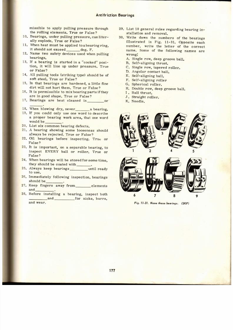
7/26/2019 Auto Service and Repair - Martin W. Stockel
http://slidepdf.com/reader/full/auto-service-and-repair-martin-w-stockel 177/224
Ant if r ict ion
Beor ings
missible
to
apply
pull ing
pressure
through
the
roll ing
elements. True
or
False
?
10. Bearings,
under
pull ing
pressure,
canliter-
ally explode.
True
or False?
11. When
heat
must
be
applied
toabearingring,
it
should
not
exceed_deg.
F.
12.
Name
two safety
devices
used when pull ing
bearings.
13. I f
a bear ing
is
star ted
in
a
t tcocked
posi -
t ion, it wil l
l ine up
under
pressure.
True
or False
?
14.
AU
pulling
tools
(striking
type)
should
be
of
soft
steel.
True
or
False
?
15. In
that
bearings
are hardened,
a l it t le f ine
dirt
will
not
hurt
them. True
or
False
?
16. I t
is
permissib le
to mixbearingpartsi f they
are in
good
shape. True
or
False
?
17. Bear ings
are best
c leaned
in
or
18.
When
blowing
dry, never_a
bearing.
19. If you could only use one word to describe
a
proper
bearing
work
area, that
one word
would
be
20.
List
six
common bearing
defects.
21.
A
bearing
showing
some
looseness
should
always
be rejected.
True
or
False
?
22.
AI
bearings
before
inspecting.
True
or
False
?
23.
It
is important,
on
a separable
beari.ng,
to
inspect
EVERY
batl
or roller. True
or
FaIse
?
24.
When
bearings
wilt
be
storedfor
sometime,
they
should
be
coated with_.
25. Always keep bearings_until ready
to
use.
26.
Immediately
following
inspection,
bearings
should
be--.
2?.
Keep
fingers
away from_elements
¡n¡ l
28.
Before
instalting
a
bearing,
inspect
both
and
-for
nicks, burrs,
and wear.
List
10
general
rules
regarding
bearing
in -
stallation
and
removal.
Write
down
the
numbers
of
the
bearings
i l lustrated
in Fig.11-31.
Opposi te
each
number,
write
the
letter
of
the
correct
name.
Some
of the
following
names
are
wrong:
A.
Single
row,
deep groove
ball.
B.
SeIf-aligning
thrust.
C.
Single
row,
tapered
roller.
D.
Angular
contact
ball.
E.
SeIf-aligning
ball.
F.
Self-aligning
roller
G.
Spherical
roller.
H.
Double
row,
deep groove
ball.
I
.
Ball
thrust.
J.
Straight
roller.
K.
Needle.
Fig. l l -31,
Nome
áese
beorings.
(Sr(F)
to
30.
177

7/26/2019 Auto Service and Repair - Martin W. Stockel
http://slidepdf.com/reader/full/auto-service-and-repair-martin-w-stockel 178/224
Auto Serviceond
Repqir
Fig. l l
-32,
Some
common
oller beoring defecfs.
Beorings showing
these
sí9ns
musf 6e
discorded.
(Codil loc)
*-+ff i
wtéK%
*,'
€
tf l
HrAl
$r5e*
ffi;
STEP
WTAR
INNTR
RA{T
RACKTÚ
l*ReTi{}r ¡
WEAR
INDTilTATIONS
¡¡ll5AllGNneENT
FRfTTlf.lC
STA¡N
DISCOIORAfION
*8thCtt, l. ¡{;
TAIIGU€
SPAIIING
TTCHIN6
SMTAR;
178
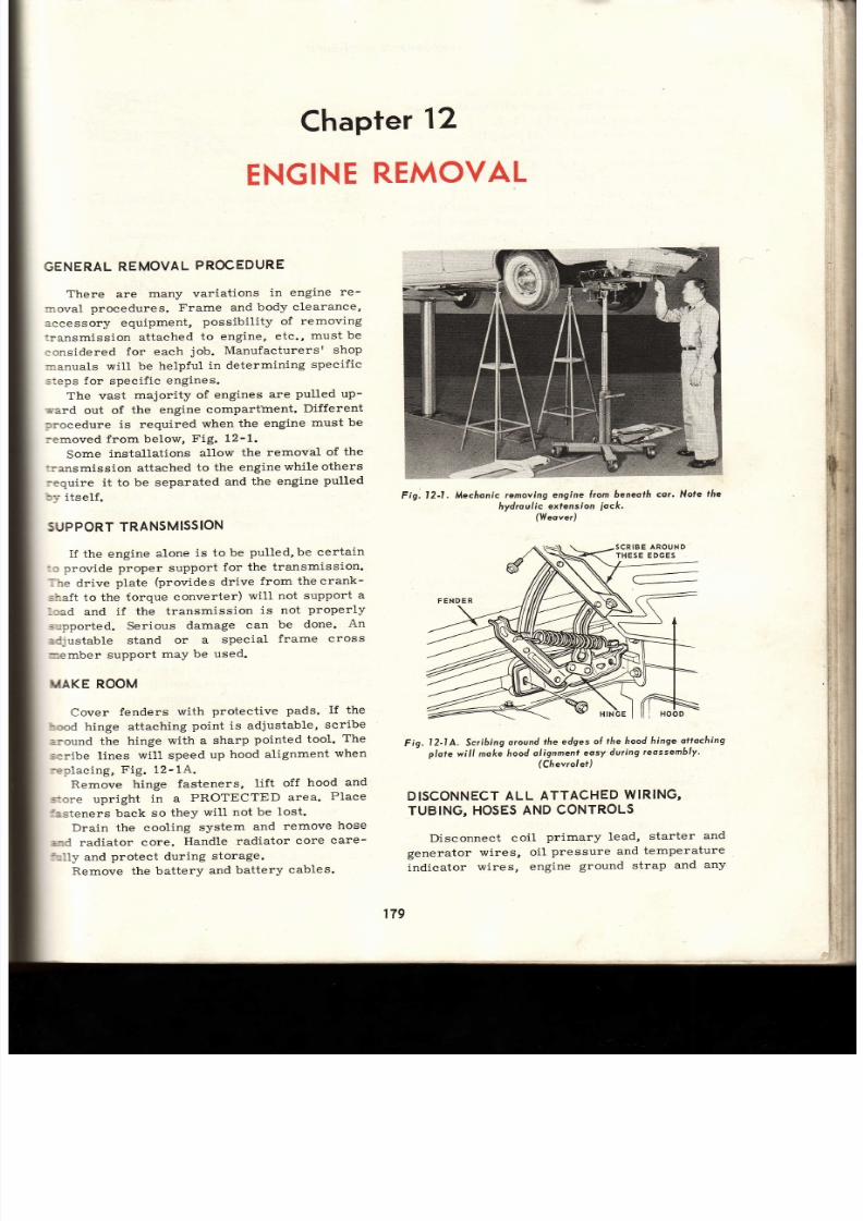
7/26/2019 Auto Service and Repair - Martin W. Stockel
http://slidepdf.com/reader/full/auto-service-and-repair-martin-w-stockel 179/224
ll
ri
i;:
l
hapter
2
ENGINE
EMOVAL
GENERAL
EMOVAL
ROCEDURE
There are
many
variations
in
engine
re -
=roval
procedures.
Frame
and
body clearance,
:ccessory equipment,
possibil i ty
of
removing
:ransmission attached
to engine,
etc.,
must be
:onsidered
for
each
job.
Manufacturersr
shop
¡anuals
wil l be
helpful
in determining
speeific
=teps for specific engines.
The vast
majority
of
engines
are
pulled
up-
rard
out of
the
engine
compart'ment.
Different
¡rocedure
is required
when
the engine
must
be
:emoved
from below,
Fig.
12-1.
Some
installations
al1or¡¡
the
removal
of
the
:ransmission attached
to the engine
while
others
:equire it to
be separated
and
the
engine
pulLed
by
itself.
SUPPORT
RANSMISSION
I f
the engine
alone
is to
be
pulled, be
certain
:: provide
proper support
for
the
transmission.
.he
drive
plate
(provides
drive
from the
crank-
shaJt to the torque
converter)
wil l not
support
a
laad and
if the
transmission
is
not
properly
s:pported.
Serious
damage
can
be
done.
An
=djustable
stand
or
a
special
frame
cross
-ember
support
maY
be
used.
IKIAKE
ROOM
Cover
fenders
with
protective
pads.
I f
the
rood hinge attaching
point is adjustable,
scribe
a¡ound the
hinge
with a
sharp
pointed tool.
The
'cribe
lines
wil l speed
up
hood
alignment
when
replac ing,
Fig. 12-1A.
Remove
hinge
fasteners,
lift off
hood
and
-ore
upright
in a
PROTECTED
area.
Place
f=.steners back
so
they
wi l l
not be
lost.
Drain the
cooling
system
and
remove
hose
s:d radiator
core.
Handle radiator
core
care-
51ly and
protect during
storage.
Remove the
battery
and
battery
cables.
Fig. l2-I.
Mecfionic
removing
engine
lrom
beneofh cor' Nofe
fhe
hydro
u i c exfension
iocft
(WeoverJ
Fig.
l2-1A. Scribing
oround
he
edges
of
the hood
hinge
ottoching
p/ole will moke
hood
alignment
easy
during
reossem6ly'
(Chevrol et )
DISCONNECT
LL
ATTACHED
¡RING,
TUBING,
OSES
ND
CONTROLS
Disconnect
coil
primary lead,
starter
an d
generator
wires,
oil
pressure
and
temperature
indicator
wires, engine
ground strap
and
an y
179
SCRIBEAROUND
THESE EDGES
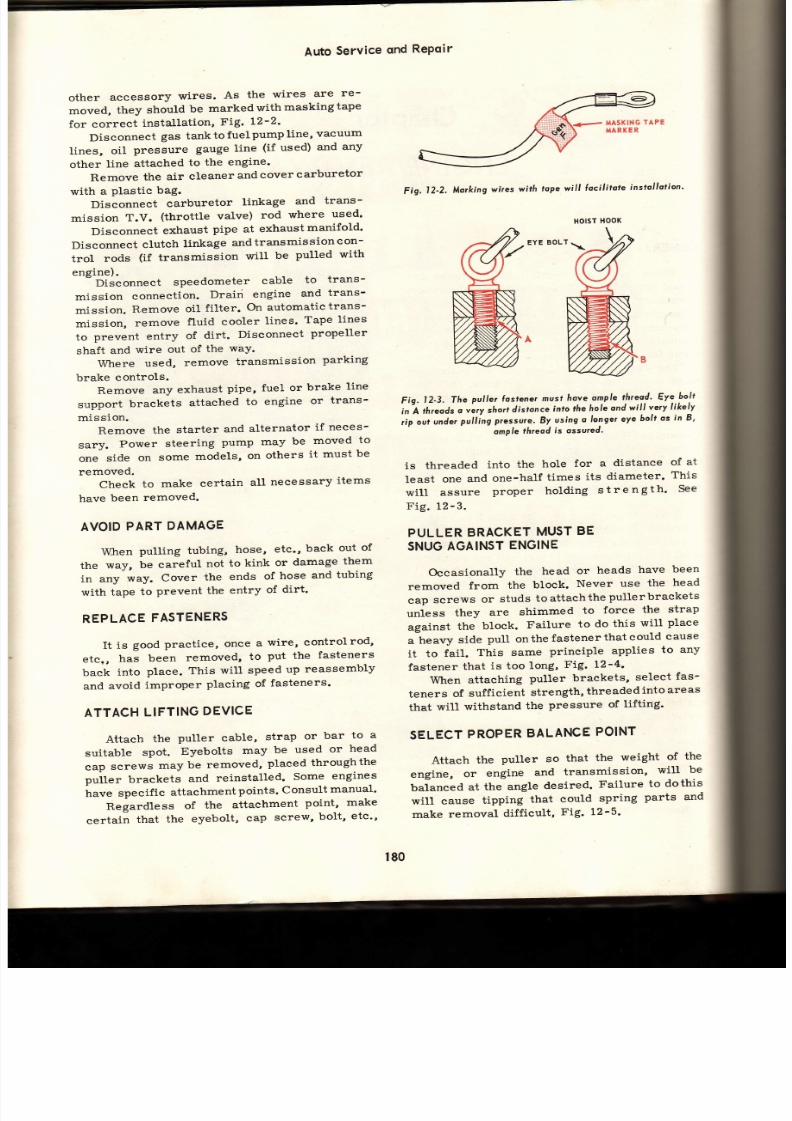
7/26/2019 Auto Service and Repair - Martin W. Stockel
http://slidepdf.com/reader/full/auto-service-and-repair-martin-w-stockel 180/224
Auto
Service
ond
RePoir
other
accessory
wires.
As
the
wires
are
re-
moved,
they
should
be
marked
with
masking
tape
for
correct
installation,
Fig.
t2-2'
Disconnect
gas tanktofuelpump
line,
vacuum
lines,
oil
pressure
gauge
line
(if
used)
and
any
other
line
attached
to
the
engine.
Remove the air cleaner and cover carburetor
with
a
plastic
bag.
Disconnect
carburetor
linkage
and
trans-
mission
T.V.
(throttle
valve)
rod
where
used'
Diseonnect
exhaust
pipe
at
exhaustmanifold'
Di
sc
onnect
clutch
linkage
and
transmis
s
on c on-
trol
rods
(if
transmission
will
be
pulled
with
engine).
Disconnect
speedometer
cable
to
trans-
mission
connection.
Drairi
engine
and
trans-
mission.
Remove
oil
fi l ter.
On automatictrans-
mi.ssion,
remove
fluid
cooler
lines'
Tape
lines
to
prevent
entry
of
dírt.
Disconneet
propeller
shaft
and
wire
out
of
the
waY.
Where
used,
remove transmission parking
brake controls.
Remove
any
exhaust
pipe,
fuel
or
brake
line
support
brackets
attached
to
engine
or
trans-
mission.
Remove
the
starter
and
alternator
if
neces-
sary.
Power
steering
pump
may
be
moved
to
one
side
on
some
models,
on
others
it
must
be
removed.
Check
to
make
certain
all
necessary
items
have
been
removed.
AVOID
ART
DAMAGE
\Áft-ren
ulling
tubing,
hose,
etc',
back
out
of
the
way,
be careful
not
to
kink
or
damage
them
in any
way.
Cover
the
ends
of
hose
and
tubing
with
tape
to
prevent
the
entry
of
dirt'
REPLACE
ASTENERS
It
is
good
pract ice,
once
a
wire, controlrod'
etc,,
has
been
removed,
to
put
the
fasteners
baek
into
place.
This
wi l l
speed
up
reassembly
and
avoid
improper
placing
of
fasteners'
ATTACH IFTINGDEVICE
Attach
the
puLler cable,
strap
or
bar
to
a
suitable
spot.
Eyebolts
may
be
used
or
head
cap
screws
may
be
removed,
placed
throughthe
prrit brackets
and
reinstalled'
Some
engines
have
specific
attachment
points'
Consult
manual'
Regardless
of
the
attachment
point'
make
certain
that
the
eyebolt,
cap
screw,
bolt,
etc
Fig.
l2-2,
Morking
wires
wítñ
tope
will
locilitote
installotion'
EYE
BOLT.
Fig.
l2-3.
The
puller losfener
nusl
hove
omple
threaé' Eye
bolt
in'A
thteods
o
.ry
hort
dístonce
into fñe
hole
ond
will
very
likely
,:ip
out
unde,
pullíng
pressu,e.
By
using
o
longer
eye
bolt
os
in B'
omPle
hreod
is
ossu¡ed'
is
threaded
into
the
hole
for
a
distance
of
at
least
one
and
one-half
times
its
diameter'
This
wi l l
assure
proper
holding
strength '
See
Fig. 12-3.
PULLERBRACKETMUST E
SNUG
GAINST
NGINE
Occasionally
the
head
or
heads
have
been
removed
from
the
block.
Never
use
the
head
cap
screws
or
studs
toattachthe
pullerbrackets
unless
they
are
shimmed
to
force
the
strap
against
the
block.
Failure
to
do
this
will
place
.
h .ty
side
pull onthefastenerthatcould
cause
it to
fail.
This
same
principle
applies
to any
fastener
that
is too
long,
Fig. t2-4'
When
attaching
puller brackets,
select
fas-
teners
of
sufficient
strength,
threadedintoareas
that
will
withstand
the
pressure
of
lifting'
SELECT
ROPER
ALANCE
OINT
Attach
the
puller so
that
the
weight
of
the
engine,
or
engine
and
transmission,
will
be
balanced
at
the
angle
desired.
FaiLure
to
dothis
will cause
tipping
that
could
spring
parts and
make
removal
difficult,
Fig. 12-5'
180
HOIST
HOOK

7/26/2019 Auto Service and Repair - Martin W. Stockel
http://slidepdf.com/reader/full/auto-service-and-repair-martin-w-stockel 181/224
PULL
POINT
MUST
NOT
SLIP
Make
certain
that
the pull
point
(point
of
attachment
on
the puller)
cannot
slip
under pres_
sure. Fig.
12-6,
shows
what
can happen
when
a
chain
hook
is placed
on
a
plain
cable
pull ing
strap.
The pul ler strap in Fig. 12-?, a l lowsthepul l
point
to
be
moved
along
the
length
of
the
cable,
but
under pressure
the
hoist
bracket
will
bind
against
the
cable
thus
preventing
slippage,
F ig.
l2-7.
POSITION
LIFT
After
the pull ing
device
is f i rmly
attached,
move
the
lift into
a
position
that
wil l
raise
the
engine
without
causing
any
undesirable
side
or
fore
and
aft
pressures.
Insert
the l ift
hook
into
the puller
and
place
a light
l ifting
strain
on the
engine. Remove the engine mount bolts.
Engine
Rernovql
Fig, l2-4.
In
A,
puller
ó¡ockers
(t)
ond
(2)
hove
slid up the
cop
screws.
Wáenñoist
exerts
force
on the puller
coble,
puller
b¡ocket
(3.)
will
lo¡ce
cop
screw
sidewoys
cousing
i¡ ¡o
break
or
6end os
slrown
in
B. ln
C,6rocket
ís
held
against
block
by o
sñorf
sectíon
of
pipe
to
prcvent
cop
screw
damoge,
D
illust¡o¡is
o typicol pull-
er 6o¡.
Note
odjusfmenf
Áoles.
Fig. l2-5.
Engine can
be
l¡f¡ed
n
o
level
posif ion
by
orronging
pull
point
os
in
A. tn
B,
t i l t ing
ongle
is
aitered
by noving pull
poinl
towords
ront
ol
engine.
Any
number
oÍ ongles
ore
poss;6/e.
Fig. 12-6.
Engine
wos
being
li lred
by
plocing
hoist
hook
oround
o.ploin
coble
puller
strop.
The reor
ol the
engine ipped
down
on d
tfie
ñoisf
/roo/<
lid to
the Í¡on¡
end oÍ
the
coble.
Tie
¡eor
ol the
engine
is now
olling
downwo¡d
with
dongerous
o¡ce.
MAKE
CER-
TAIN PULL
PO NI
CANNOT
SL P.
{
PULLER
STRAP
/ HOTST oO K
SLIDING
UP
CABLE
t8t
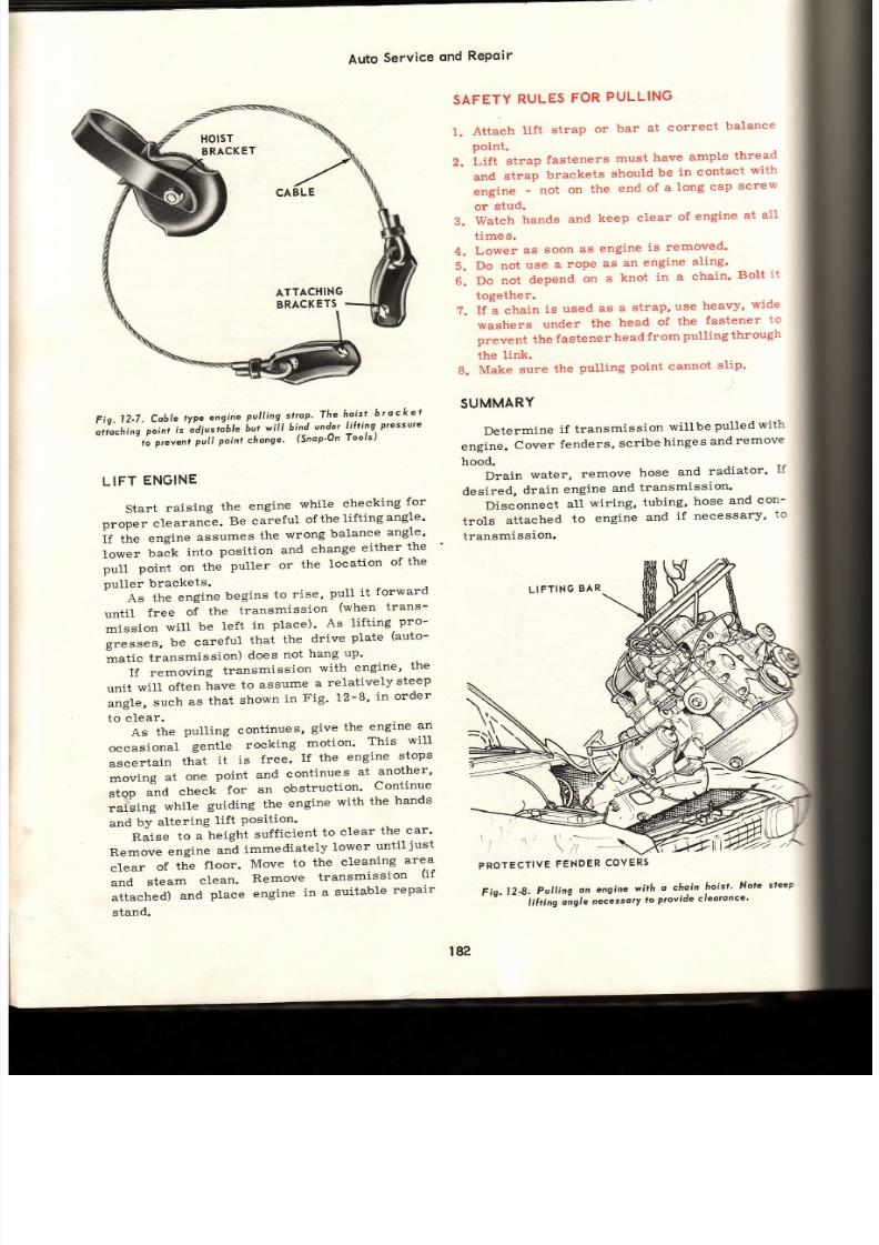
7/26/2019 Auto Service and Repair - Martin W. Stockel
http://slidepdf.com/reader/full/auto-service-and-repair-martin-w-stockel 182/224
Auto
Service
ond
RePoir
SAFETY
RULES
FOR
PULLING
1.
Attach
lift
strap
or
bar
at
correct
balance
point.
Z.
Li ft
strap
fasteners
must
have
ample
thread
and
strap
brackets
should
be
in contact
with
engine -
not
on
the
end
of
a
long
cap
screw
or
stud.
3.
Wateh
hands
and
keep
clear
of
engine
at
al l
t ime
s.
4.
Lower
as
soon
as
engine
is
removed'
5.
Do not
use
a
rope
as
an
engine
sling'
6.
Do
not
depend
on
a
knot
in
a
chain'
Bolt
i t
together.
?.
If a chain
is
used
as
a
strap,
use
heavy'
wide
washers
under
the
head
of
the
fastener
to
prevent
the
fastener
head
from
pulling
through
the
link.
B.
Make
sure
the
pulling
point cannot
slip'
SUMMARY
Determine
if
transmission
willbe
pulted
with
engine.
Cover
fenders,
scribe
hinge
s
and
remove
F¡o. 12-7.
Coble
tvpe
engine
pulling
slrop'
Th.e
r.ois-t
6 ¡ o c
k
e
t
' ii l-,r,
,.,r,
i,
od¡ ro6le
hut
will
bind
under
lifting
pressure
- ' ' r i
or
venl
p 'u l l
poinl
chonge'
(Snop-On
ools)
LIFT
ENGINE
Start
raising
the
engíne
while
checking
for
proper
clearance.
Be careful
of
the
lif t ingangle'
If
the
engine
assumes
the
wrong
balance
angle'
lower
back
into
posit ion
and
change
either
th e
pull
point
on
the
puller
or
the
location
of
the
puller
brackets.
t forward
As
the engine begins to rise' Pull i.
unt i l
f ree
of
the
transmission
(when
trans-
mission
will
be
left
in
place)'
As
lif t ing
pro-
g ,
be
careful
that
the
drive
plate
(auto-
áatic
transmission)
does
not
hang
up '
If
removing
transmission
with
engine'
th e
unit
will
often
have
to
assume
a
relatively
steep
angle,
such
as
that
shown
in
Fig'
12-8'
in
order
to
clear.
As
the
pulling
continues,
give the
engine
an
occasional
gentle
rocking
motion'
This
will
ascertain
that
i t
is
free.
I f the
engine
stops
moving
at
one
point
and
continues
at
another'
stop Ád check for an obstruct ion' Continue
i tü
wnite
guiaing
the
engine
with
the
hands
and
bY
altering
lift
Position
Raise
to
a
height
suff icient
to
clear
the
car'
Remove
engine
aná
immediately
lower
until
just
clear
of
the
floor.
Move
to
the
cleaning
area
and
steam
clean.
Remove
transmission
(i f
attached)
and
place
engine
in
a
suitable
repair
stand.
hood.
Drain
water,
remove
desired,
drain
engine
an d
Disconnect
aI1
wiring,
trols
attached
to
engine
transmission.
LIFTTNG BA R
hose
and
radiator.
If
transmission.
tubing,
hose
and
con-
and
if
necessarY,
to
\)
\ |
{i
l r
'
\ /
PROTECTIVE
\
,i:
FENDER
COVERS
HOlST
BRACKET
ATTACHING
BRACKETS
t82
Fio.l2 '8,
Pull ing
an
engíne
wí t f i
a
chain
hoisf '
Note
steep
'
' t '
' - -
t¡ ir¡nn
oí9lt
n t oty
to
provide
cleoronce'

7/26/2019 Auto Service and Repair - Martin W. Stockel
http://slidepdf.com/reader/full/auto-service-and-repair-martin-w-stockel 183/224
Engine
Rernovol
Attach
puller
strap
securely
to
properly
balance assembly.
PulI
engine
slowly,
checking
to make certain
all
parts
are
free.
When high enough
to clear,
remove and
lower.
Steam clean
and
place in a
repair stand.
Be
very careful.
Keep
clear
of engine
at a1l
t imes.
1
OUIZ
-
Chopter
2
Engines must always
be
pulledwith:
(-).
a.
Transmission attached.
b.
Transmission
removed.
c.
Varies
-
sometimes
attached,
sometimes
removed.
If
adjustabl€,
-oround
hood
hinges be-
fore removal.
Whenever
pract ical,
always-fasten-
ers after
part
is removed.
wire
ends
after removal
to
facil i-
tate reassembLy.
5.
Engine
angle
duringlif t ing shouldbe
(-).
a.
Level.
b.
Back t ipped down.
c.
Front t ipped down.
d.
Depends
on
job
at
hand.
6. As soon as the engine wi l l clear the car,
and
A
gentle_motion
will help to
de -
termine
if
engine
is
clear
during
pull ing.
Lif t
strap
or
barbrackets shouldbe attached
to:
(_).
a.
Head bol ts .
b.
Intake
manifol.d.
c.
Exhaust manifold.
d. Depends on
situat ion.
9. When
pulling
tubing
free
of
ful to
avoid
10.
List
seven safety
rules
fo r
A
n
8.
2
a
engine,
be care-
engine
pull ing.
Tronsverse
cross-sectiono/
view
ol an
overheod
comshah, 6-cylinder,
Íuel injected
gos
engine.
(Mercedes Benz)
t93

7/26/2019 Auto Service and Repair - Martin W. Stockel
http://slidepdf.com/reader/full/auto-service-and-repair-martin-w-stockel 184/224
Auto
Service
ond
Repoir
Curowoy
view of a
six cylinder
engine
in which
the
6/oc/<
is
slonted
fo
one side.
Plymouth)
184

7/26/2019 Auto Service and Repair - Martin W. Stockel
http://slidepdf.com/reader/full/auto-service-and-repair-martin-w-stockel 185/224
Chapfer
3
CYLINDER
EAD,
ALVE
ND
VALVE
RAIN
SERVICE
CYLINDER
HEAD
REMOVAL
Never
remove
a
cylinder
head
unti l the
en-
gine
has
cooled. Removal
while
hot
wil l
very
I ikely
eause the
head
to warp
upon
cool ing.
Remove
intake
and exhaust
manifolds
(when
required) ,
spark
plugs,
wires,
rocker
arm
cov-
er
and
any accessory
uni ts
attached
to
the head.
REMOVING
ROCKER
ARM
ASSEMBLY
Remove
the rocker
arm
assembly
by
star t-
ing
at
one end,
and loosening
each
support
bracket
bolt,
one
after
the
other,
a
couple
of turns.
Re -
peat
unt i l
the
assembly
is free.
I f
each bracket
bol t
is
completely
removed
before
movingtothe
next,
the
last
bracket
could be
damaged
by the
valve
spring
pressure
pushing
the free
portion
of
the
shaft
upward, Fig.
13-1.
Fig.
l3-1,
Loosen ¡ocke¡
otm
suppott
brocket
cop screws,
on e
olte¡
the
othe¡, a l i tt le
ot o
tine.
(Plynouth)
On
engines
using ball
stud
type rocker
arms,
loosen
each bal l
nut
unt i l
the rocker
armcan
be
swiveled
sideways
to
c lear the
push
rod,
Fig.13-2.
-ooJUsrNG
NUr
W-BALL
SwtvEL
ROCKER
RM
Fig. l3-2.
Loosen
odfusfing
ul
enough
o ollow
rocker
orm o
swive/sidewoys6usc/eoring ush
od.
(G.M.C.)
In
cases where
rocker
arm
shaft support
brackets
are
an
integral
part
of
the head,
the
head
may
be
pul led
before
st id ing
the rocker
shaft
out of
the brackets.
REMOVE
PUSH
RODS
Remove
and
place
each
push
rod
in
a
marked
holder
so
i t
can be
replacedinthe
or ig inal posi-
t ion.
A holder
such
as shown
in
Fig.
13-3, wi l l
suff ice.
LOOSEN
CYLINDER
HEAD
FASTENERS
Using
the recommended
tightening
sequence,
reverse
the
order
and crack
( just
break
loose)
each
head
cap
screw. Once
aII have
been loos-
ened,
they may
be removed.
If
lengthvar ies
or i f
PUSH
SUPPORTBRACKET
CAP
SCREWS
18s

7/26/2019 Auto Service and Repair - Martin W. Stockel
http://slidepdf.com/reader/full/auto-service-and-repair-martin-w-stockel 186/224
MARKS
FOR
LEFT
AND
RIGHT
BANKs
'Y::2222
IÑDICATES
FRONT OF
EÑGINE
Fig,13-3,
Ploce
push rods
in o mqrked
holder
-
in
proper order'
a
cap
screw
is dr i l led
or
machinedforoi l
pass-
age,
note
the correct
locat ion,
Fig.
13-4.
I f the cy l inder
head
is stuck,
use
prybars or
a
lead hamrner. Be careful not todamagethehead.
Fíg.
13-4.
Crock
cylinder
heodcop
screws
oose'
Remove
n
the
everse
¡der
Í t íghtening.
Plymouth)
Avoid
jamming
any
tapered
object
between
head
and
block
mating
surfaces
as
the
slightest
nick
or
dent
may cause
ser ious
damage'
Whenheadis
loose,
remove,YFig.
13-5.
PLACE
CYLINDER
HEAD
IN HOLDING
FIXTURE
l -o l lowing
removal,
place the cy l inder
head
in a suitable
repair
stand.
Compress
the
valve
spr ings,
remove
the
spl i t
keepers,
spr ing
and
spr ing
retainer
assembly,
Fig.
13-6.
Auto
Serviceond
RePoir
KEEP
VALVES IN
ORDER
As they
are removed,
place
valves
in a
rack
so they
may
be replaced
intheir
or ig inal
guides.
Use a
rack
simi lar
to
that shown
inFig. 13-3.
VALVES
ELL
A STORY
Inspect
each
valve
for s igns ofburning,
pi t t inr
and
heavy carbon
deposits.
Burned or
pit tec
valves
can
be causedbyvalves
st ick ing
in
guides-
insuf f ic ient
tappet
c learance,
weak
spr ings,
c logged
coolant
passage,
warped valve
stem,
improper
igni t ion or
valve
t iming,
etc. ,Fig.
1 3-8.
Heavy
carbon
deposits ,
especial ly
under
th e
head of
the
intake valve,
indicates
worn valve
guides,
damaged
sea1s,
worn rocker
arm
bush-
ings
allowing
overlubricat ion,
clogged
oil
drair-
Fig.
l3-5. Removín9
ylínder
heod'
Note
Ii Í¡ brockets.
(G.M.C.)
CYLINDER
HEAD
ASSEMBLY
SPLIT
KE
E
P
REPAIR
STAND
Fig.
l3-6.
Removing
splí l
(Chrysler)
18ó
volve
keepers.
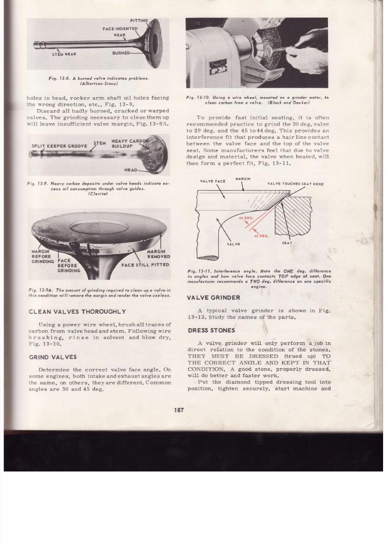
7/26/2019 Auto Service and Repair - Martin W. Stockel
http://slidepdf.com/reader/full/auto-service-and-repair-martin-w-stockel 187/224
Fig,
l3-8,
A
burned olve ndicoles
roblems.
(A
be¡ts nSioux
holes in head, rocker arrn shaf t o i l
holes
facing
- i- :
rvrong
direct ion, etc. ,
Fig.
13-9.
Discard
al l
badly burned, cracked
or
warped
. a lves.
The
gr inding
necessary to c leanthemup
, i .11
leave insuf f ic ient valve
margln,
Fig.
13-94.
Fiq,
l3-10.
Using o wire
wheel,
mounted
on
o
grínder
molor,
to
cleon co¡bon
{rom
o
volve.
(Block
ond
Decker)
To nrowide f ¡s t
in i t ia l seat ino. i t
is of ten
recommended
pract ice
to
gr ind
the 30 deg. valve
to 29 deg. and the
45
to44 deg.
This provides
an
inter ference f i t that
produces
a hair l inecontact
between the valve
face and the top
of the valve
seat . Some manufacturers feel that due to valve
design
and mater ia l , the valve
when heated,
wi l l
then form
a
perfect f i t ,
Fig.
13-11.
Fig.13-Il . lnte¡{erence
ongle.
}.{ote
the
ONE
deg. diÍlerence
in ongles and
how
valve
lace contocfs
TOP
edge of seof.
On e
monuloctu¡er recommends o
TYIO
deg. di l le¡ence on one specific
engine.
VALVEGRINDER
A
typical
valve
grinder
is
shown
in
Fig.
13-12.
Study
the names
of the
parts.
DRESS TONES
A valve grinder wil l only perform a job in
direct
relat ion to the
condit ion of
the
stones.
THEY
MUST
BE DRESSED
(tTued
up)
TO
THE
CORRECT ANGLE AND KEPT IN THAT
CONDITION.
A
good
stone,
proper ly
dressed,
wil l do better and faster
work.
Put
the diamond
tipped dressing tool
into
posit ion,
t ighten
securely, start
machine
an d
l3-9, Heovy corbon
deposifs under
cess oi l consumptíon
hrough
(Clevíte)
volve Ireods indicote ex-
volve
guides.
:,1
;É
r¡f
i
l,
ft
3ig.
13-9A,
The
omounl ol
grlnding
required to cleon up o
volve in
r is
condition wil l
remove the morqin ond render
the volve
useless.
CLEAN VALVES THOROUGHLY
Using
a
power
wire
wheel,
brush al l t races
of
larbon f rom
valve
head
and
stem.
Fol lowing
wire
: rushing,
r inse
in
solvent andblow
dry,
i rg. 13 - 10.
GRIND
VALVES
Determine the
correct
valve
face angle.
On
some
engines,
both intake and exhaust angles
are
:he
same, on
others,
theyare
dif ferent .
Common
a.ngles
are
30
and
45 deg.
SPLIT
KEEPER ROOVE
VALVE
TOUCHES
EAT
HERE
MARGIN
FACE
STILL
PITTED
187

7/26/2019 Auto Service and Repair - Martin W. Stockel
http://slidepdf.com/reader/full/auto-service-and-repair-martin-w-stockel 188/224
Auto
Service
ond
Repoir
WHE
L
CARRIAGE
CHUCK
Fig.
l3-14. Setfing
volve
chuck
to the desired ongle
PLACEVALVE NCHUCK
Place the valve
in the
chuck.
Various
grippin;
devices
are used so
fol1ow
manufacturerrs
rec-
ommendations.
Make
sure
the valve
is in
th =
F
s. l3-15. ln A,
the
volve
protrudes
loo {ar out
ol lhe
chuck
or :
wi l l chotter.
In
B,
the
volve
deplh
is
correcl.
cltucK
SWI
VE
L
NU T
CHUCK
AN6LE
ALIGNME}I
CHUCK
WIVEL
NGLE
LOCKING
UT
ADDLE
TRAYEL EVER
Fíg. 13-12. A
typicol
volve grinding machine.
advance stone
SLOWLY
toward
the diamond.
When
the
diamond
just
touches,
turn
on the
coolant
and
move the
diamond
back and
for th
across
the
stone unti l
the stone
is smooth, clean
and
true. Several
VERY
FINE
cuts
may be re-
quired.
Move
the
diamond s1ow1y,
Fig.
13-13.
Fig. l3-13, Dressíng
the grinding
wheel with a diomond
dresser.
SETCHUCK
NGLE
Loosen
chuck
swivel
nut and swing
chuck
to
the
proper
angle.
Adjust the
chuck
alignlng
edge
to the selected
angle
marking very carefully.
Lock
swivel
nut and
recheck
angle setting,
Fig.
13- 14.
DIAMOND
IP
r88
Fig.
l3-16.
Adiusting
volve
stem depth
n
¡he
chuck.

7/26/2019 Auto Service and Repair - Martin W. Stockel
http://slidepdf.com/reader/full/auto-service-and-repair-martin-w-stockel 189/224
Cylinder Heod,Volve,
Vqlve
Trqin Service
chuck far
enough
so an excessive amount does
not protrude
and cause chatter
(valve
vibrating
dur ing gr inding),
Fig.
13-15.
Fi .g.
13-16, shows
a valve being
placedinthe
chuck.
Close
chuck t ight ly.
CHECKFOR
RUNOUT
Turn
on
the
chuck and
watch
the valve as it
rotates.
If
a noticeable
amount of runout
(wobble)
is present ,
stop the
chuck, loosenandreposit ion
the
valve.
If
excessive
runout is st i l1
present,
a
warped
stem is indicated. I f warped
to the
point
that grinding
will leave insuff i.cientmargin,
dis-
card
the valve, Fig.
13-1?.
MARGIN
Fig.
l3-18.
ll
¡he
chuck
s
sel ot the
proper
ongle,
the
volve
Íace
ond slone wil l be
porol le l
os in
A,
STONE
Fig. I3-19. lhen
grinding,
ove he vo/ve ock
ond orth
keeping
the
volve oce n
Íull confoctwilfi fñe sfone.
stone to run a
few
seconds
without
advancing
it ,
then
carefullyback the stone awayfrom the valve.
Disengage the chuck drive and rotate the
valve by hand
while
examining closely
for
an y
remaining
pits,
burns, etc.
The
valve
face
should
be bright,
smooth and
free
of
ALL
defects.
Th e
margin
should
be ample
Í132
in.
or
more). I f
the
valve is not cleaned up, repeat
the
process.
When
finished, inspect
the
micrometer feed
dial
and mark down
the amount of material removed
from
the
valve.
Return
the valve
to the holder.
Using
the same
procedure, grindthe
remain-
ing
valves. Do not forget
to ehange angles
if in-
take
and exhaust are dif ferent.
WHEN
FIRST
USING
A VALVE GRINDER,
PROCEED
SLOWLY.
MANY BEGINNERS IN-
ADVERTENTLY TURN THE
STONE
FEED
WHEEL
THE
WRONG WAY
OR TOO FAST AND
JAM IT AGAINST
THE
VALVE.
IF THE CUT
IS
SUDDENLY
TOO HEAVY, DO NOT PANIC AND
CRANK
THEWIÍEEL
-
YOUMAYTURNITTHE
WRONG WAY.
SHUT
THE
MACHINE OFF AND
WHEN
STOPPED
MOVE
STONE
AWAY.
A
VALVE
FACE
ffi;l'ffi-,
LLE LAR
z>
INOT PARALLEL
WARPED
TE M
Y\
I
NO
MARGIN
t_¡
MARGIN
Fig.
I3-17.
Excessive
volve wobble
-
A,
wil l couse fhe
vo lve
morgin to 6e removed
on one edge, B.
GRIND ALVEFACE
Move
the
chuck
saddle
until
the
valve
is in
front
of
(not
touching)
the stone.
Turn
on the
machine,
engage
chuck
drive to spin
valve,
turn
on the
coolant and advance the
wheel
toward
the
valve. The
valve
face
and stone shouldbeparal-
1el i f you
have
selected the
proper
angle,
F ig.13-18.
If
parallel,
slowly aovance
the stone
(make
sure
valve is
turning)
until
it
just
starts to cut.
Move
the valve face back
and
forth
across the
stone. NEVER RUN THE
VALVE
OFF TIIE
STONE, F ig.
13-19.
If
your
machine has a micrometer
feed,
se t
i t to
zero
at
the
point
where
the stone
just
starts
:o
cut. Advance the stone against
the valve
around
.001
to
.002
at a
time.
Watch
the valve
face
and as
soon as all dark spots disappear,
center the
valve
face
ón the stone, allow the
+
i1
189

7/26/2019 Auto Service and Repair - Martin W. Stockel
http://slidepdf.com/reader/full/auto-service-and-repair-martin-w-stockel 190/224
The
operator
in
Fig.
13-20,
is
gr inding
a
valve
face.
Notice how the stone
feed
wheel is
grasped. Even
though
it ha s a crank
knob,
once
the stone
is
close
to the valve,
holdit as
shown.
This method
wil l
permit
smoother
and
rnore
accurate
adjustments.
Fig. l3-20. Grinding
he volve
(oce.
(Al6e¡tson-S
oux,)
GRIND
VALVE STEM
END
The
valve stem end
shouldalwaysbetruedup
and smoothed by grinding. If you have marked
down the
amount
removed
from each valve
face,
it
is recommended
that
you
remove a comparable
amount
from
the stem.
This wil l help in
main-
taining original
tappet
clearance.
However,
never remove an excessive amount
(up
to about
.010)
as the sur face
hardening
is nottoodeep on
some valves.
If ground
below
the hardening,
rapid wear wil l result.
Dress
the s ide of
the
wheel
used
for
stem
grinding.
Chuck the valve
in the
V-blockholder,
and run
i t in
unti l
i t
just
touches
the stone.
If
so
equipped,
set
the micrometer
feed
dial
to zero.
Back
off the valve, start
the
wheel,
turn on
the
coolant
and advance
the stem against
the
wheel.
Continue advancing
with l ight cuts unti l
th e
micrometer dial
indicates that
you have re-
moved
the same
amount as
was taken from
th e
face. As
with
valve
face
grinding,
direct a
good
stream
of coolant on
the
portion
of the valve
being
ground.
Auto
Serv¡ceond
Repq¡r
Fig.
l3-21.
Truing the
volve
sfem end.
(Von
Norman)
I f
the machine
has no micrometer feed, re-
move
enough
to
produce
a smooth square
end,
Fig.13-21.
When using a
plain
V-block,
in
which
the valve
must
be
hand
held, make
certain
the block
is
close
to the wheel to
prevent
the valve
stem
from
catching
and
pull ing
the valve
between
block and
wheel.
Position
the valve stem
in the
block,
hold
down
firmly
and
advance stem against
wheel,
Fig.13-22.
F--
t
Fig.
13-22. Keep
V-6lock
close
to the
grinding wheel
os
in
A.
The
setup
n
B
is dongerous
CHUCK
ADDLE
ST
V
BLOCK HOLDER
t90

7/26/2019 Auto Service and Repair - Martin W. Stockel
http://slidepdf.com/reader/full/auto-service-and-repair-martin-w-stockel 191/224
Cylinder
Heod,
Volve,
Vqlve
Troin
Service
CHAMFER
ALVE
STEM
END
If
much
of
the
chamfer
on the
valve
stem
:nd
has
been
removed
through
wear
and re_
iacing,
the
chamfer
may
be
renewedbygr inding.
?Iace
the
valve
in the
V-b1ock,
set the
holder
at
i5
deg.
and
adjust
stop
to
gr ind
about
a
l l32 in.
:hamfer,
Figs.
1B-23
and
13-23A.
REMAINING
HAMFER
r/32
tN.
NEW
CHA^{F
_l_/
Tffiffiil'
f l l i i l ] l f l
|rr]HIU
fÍ'lT--------Ítn
l l l l i l , l l l l i l
illlillru
B
Fig. I3-23A. Grinding o new chomle¡ on the valve stem end.
EACH
VALVE
MUST
PASS
NSPECTION
Inspect
each
valve
face.
I t
must
be
smooth
and
free
of
a1l
pi ts , gcratches,
burns,
etc.
There
rrust
be
ample
margin
remaining
to
prevent
burning.
Valve
stem
wear
must
notbe
excessive
and
the
stem
should
be f ree
of nicks,
scratches,
etc., .
that
could
cause
eventualbreakage
or st ick_
ing.
Keeper
grooves
must
be
undamaged.
Valve
stem
end
must
be
smooth,
squared
and
lightty
chamfered.
CAUTION:
SOME
VALVES
US E
A
SPECIAL
COATING
SUCH
AS
NICKEL-
CHROME, ETC., ON THE FACE AREA AN D
ONLY
A
LIMITED
AMOUNT
CAN
BE
RE-
MOVEDI
Check manufacturerrs
speci f icat ions.
Fig.
13-24
i l lust rates
two
valves:
one
is
ac _
ceptable,
the
other
is
not.
z .- /
taRG|N
GooD
B
I
3-23,
Volve
stem
end
in
A hos
chom(er
wo¡n
B,
o{te¡
renewing
he
chomler,
ol(.
The
some
n
ExcEss
lK '^'
Ll
KEEPEI
ffi*-..-SlilXi
R.oor,
*o *
EXCESSIYE
KEEPER
G ROOVE
DAMAGED
Fig.
l3-24.
Yolve
A
is
occeproble.
Volve
B is
nor.
WASH
AND
STORE
Following
the f inal
inspection,
each
valve
must
be
thor
oughly
washe
d
(check
keeper
grooves
carefully)
and
blown
dry.
place
in
a
clean
rack
and
cover
unt i l
readv
to
use.
CLEAN
CYLINDER
EAD
If
the
cyl inder
head
coolant
passages
are
bad-
Iy
clogged, give
the
head
an init ial
cleaning
in
a
hot
tank.
Remove
all carbon from the com-
bustion
chambers
and
valve
ports.
Wire
brushes
in
a hand
dr i l l
wi l l
do
nicely.
Clean
the
head
to
block
surface
with
a
scraper. Be
careful not
to
put
scratches
in
the
surface,
Fig.
13-25.
Run
a
spr ing-type
valve guide
cleaner
up
and down
through
each
guide
to
remove
th e
carbon, Fig.13-26.
ORIGINAL
CHAMFER
sEAL
GROOVE
KEEPER
GROOVE
,*oorn/
t9l

7/26/2019 Auto Service and Repair - Martin W. Stockel
http://slidepdf.com/reader/full/auto-service-and-repair-martin-w-stockel 192/224
Fig,
l3-25.
Removing
corbon
rom
cylinder
heod.combustion
hom-
bers
ond
Ports.
(Block
ond Decker)
Fig'
3'26, Removing
orbon
rom
he
volve
guides'
Follow the
valve
guide cleaner
with a
valve
guide brist le
brush
to remove
all
loosened
car-
bon,
Fig. 13-27.
Blow all
dust
and carbon
from the
combustion
chambers,
ports and
guides.
Push
a
clot l: ,
moistened
with
solvent,
through
all
the
valve
guides
to
make
certain
NO
foreign
materia-
remains.
This
is very
important
because
if some
is left
in the
guide,
the
stemclearance
check
wi'-
not
be accurate
and
when the
seat
grinding
pilc:
is
inserted,
it
wil l
be t ipped
and
throwthe
valv:
seat out of ali.gnment.
CHECK
ALVE
STEM
TO
GUIDE
LEARANCE
When
deciding
whether
or
not
to
use
the
o1 i
valve
guides,
you are
not 'coneerned
about
to c
1it t1e
clearance
(unless
new oversize
stemValves
are
being
installed).
ExceÉsive
clearance
wil-
often
be
present.
ihis
wil l
promote
oil consumF-
t ion,
poor seating
and
possible valve
breakage,
Fis.13-28.
VALVE
GUIDE
HEAD
VALVE
GUIDE
BRISTLE
RUSH
HAND
DRILL
STRIKES
HERE
LARGE
GA P
Fig.13-27.
Removing
oosened
corbon
rom
o
volve
guíde'
(Black
ond
Decker/
Fig.
t3-28. Excessive
olve
guideweo¡wi l l
couse
rouóle'
Two methods
are
commonlyusedtocheck
for
excessive
stem
clearance.
A
small
hole
gauge
(some
valve
seat
grinder
pitots
can
be
usedtool
is carefully
f it ted
to the
largest
valve
guide
diameter
(do
not
measure
exhaust
guide
counter-
bores),
removed
and measured with an outside
micrometer.
The valve
stem
is then
miked
at
a
corresponding
wear
area,
and
the
dif ference
computed,
Fig.
13-29.
Another
method
is
to
drop
the
valve
into
posit ion with
the
head
just
free of
the seat.
It
can
be
heLd
in this
posit ion by a special
insert
192

7/26/2019 Auto Service and Repair - Martin W. Stockel
http://slidepdf.com/reader/full/auto-service-and-repair-martin-w-stockel 193/224
Cylinder Heod,
Volve,
Fig.
l3-29.
Usingo
smoll
hole
gauge
o
meosure
olveguide
n-
side diomerer._
-f
er{;ct
Circl:)
r-
l
--
,'
or
by slipping
a
piebe
of rubber
tubing of the
correct length
over the valve stem,
Fig.
13-30.
A
dial indicator is
then
clamped
to the head.
The
indicator
stem
is
placed
against the valve
margin. Without
raising
the valve, move it back
and forth
against the stem.
Watch
the
indicator
l3-30.
Positioning
volve priorto
checking stem lo
guide
cleor-
once
wilh
o diol indicoto¡.
(Chrysler)
Volve
Troin
Service
to determine
the travel in thousandths. Re
-
member that the reading
wil l not
be the
actual
c learance because
the measur ing
point
is
above
the
guide. The
tipping
effect
wil l
magnify the
reading.
Fol low
the manufaeturerrs
recom-
mendations for
maximum
al lowable shake,
Fig.13-31.
EXCESSIVE
LEARANCE
Engine
design, type
of oi1 sea1,
amount
of
Iubr icat ion,
etc ., a l1 determlne
acceptable
c lear-
ance. Fol low
manufacturerrs
speci f icat ions.
General ly , when
the
actual clearance exceeds
.005
to.006, i t is
considered
excessive.
Remember that both
the
guide
and stem
wear
less in
the
center .
Even
though a
stem-to-guide
clearance at the
center is
correct, the
c lear-
ance
at the ends may
be excessive and
cause
tipping, Fig.13-32.
tll
CENTER
CLEARANCEO. K,
VALVE
STEM
GUIDE
Fis.
END CLEARANCE
EXCESSIVE
(((,
i:-'\\)
Fig. l3-32,
Sten
to
guide
c/eoronce neor the
end
ol ¡he
guide
must
be wi¡hin
/imifs. Note
lhat
cor¡ec
clearonce
in
lhe
guide
cenler
wíl l not prevenl
tipping.
When
an excessive stern to
guide
clearance
is present,
the
valve
guides
(if
removable) may
be replaced.
When
the
guides
are
integral
(part
of the head), they may be reamed to overs ize,
and new valves
with
oversize stems
installed,
Fig.13-33.
REPLACINGALVE
GU¡DES
The guides
may either be driven or
pressed
out.
The punch
should
have
a
pilot
section ex-
tendi.ng into the
guide.
The
pilot
should
be
a
fe w
thousandths
smaller than the
guide
hole to
pre-
F
s. l3-31.
Checking
volve
lo
guide
stem sho/<e
fo dele¡mine
sfem
cleoronce.
193
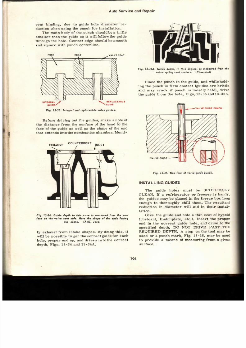
7/26/2019 Auto Service and Repair - Martin W. Stockel
http://slidepdf.com/reader/full/auto-service-and-repair-martin-w-stockel 194/224
vent
binding,
due to
guide hole diameter
re -
duct ion
when
using
the
punch for installat ion.
The main body of
the
punch
shouldbe
a tr if le
smaller than
the
guide
so
it
wil lfollowthe
guide
through the
hole.
Contact edge should
be smooth
and
square
with
punch
centerline.
PORT HEAD VALVE SEAT
Auto
Service
qnd
Repq¡r
TNTEGRAL
/
GÚIDE
'
\
REPLACEABLE
\
GUIDE
Fig. l3-33. lntegral nd eplaceobleolveguides'
Before driving out
the
guides,
make
anote of
the
distance
from the surface
of the
head
io the
face of
the
guide
as
well
as
the shape
of the end
that extends
into the
combustion
chamber.
Identi-
COUNTERBORE
Fig. 13-34, Guide
depth
in tlrís cose is r¡eosu¡ed lrom lhe sur-
foce on the volve seof side. Note tñe shope ol the ends Íocing
ffie seofs.
(AMC
Jeep)
fy exhaust
from
intake shapes.
By doing
this,
it
wil l
be
possible to
get
the
correct
guide for each
hole,
proper
end
up, and
driven
intothe
correct
depth,
F igs.
13-34 and
13-344.
Fig.13-34A,
Guide
deprh, n th is
engine,
s meosured
rom the
valve
spring
seof
su¡foce.
(Chevrolet)
Place the
punch
in the
guide,
and
whilehold-
ing the
punch in firm
contact
(guides
are brittle
and
may crack
if
punch
is loosely
held), drive
the
guide f rom the
hole,
Figs.
13-35
and 13-354.
VALVE GUIDE PUNCH
Fig.
l3-35.
One o¡m
oÍ volve
guide
punch,
INSTALLING UIDES
The
guide holes
must be SPOTLESSLY
CLEAN.
If
a
refrigerator
or
freezer
is handy,
thé
guides
may be
placed
in the
freeze box
long
enough
to thoroughly
chill
them.
The
resultant
reduction
in diameter
will
aid
in their
instal-
lation.
Give
the
guide
and
hole a
thin
coat
of
hypoid
lubricant, (Lubriplate, etc.). Insert the proper
end
in the correct
guide
hole, and
drive to
the
specified
depth.
DO
NOT DRIVE
PAST THE
REQUIRED
DEPTH. A stop on
the tool
may
be
used or a
punch mark,
Fig.
13-36,
may
be used
to
provide
a
means of
measuring
from a
given
surface.
EXHAUST
t94
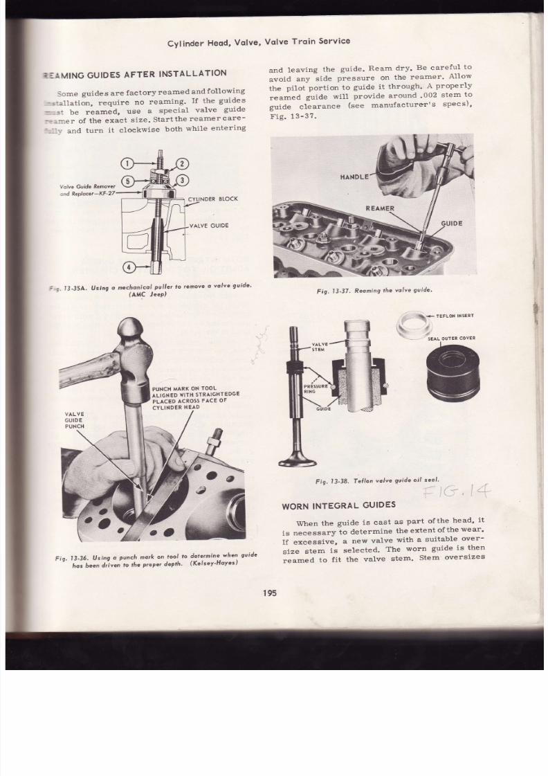
7/26/2019 Auto Service and Repair - Martin W. Stockel
http://slidepdf.com/reader/full/auto-service-and-repair-martin-w-stockel 195/224
CYlinder
Heqd,
Volve,
E:AMING GUIDES
AFTER
INSTALLATION
Some
guides are
factory
reamed
and
f ollowing
-. : . l lat ion,
require
no
reaming'
I f the
guides
:- *; : be
reamed,
use
a
special
valve
guide
-;:r:rer of the exaet s ize. Star t the reamer care-
'--- ', -
and
turn
it clockwise
both
while
entering
Volve
Guide
Remover
:nd Replocer-KF
Vqlve
Trqin
Service
and
leaving
the
guide.
Ream
dry'
Be
careful
to
avoid
any
side
pressure
on
the
reamer'
Allow
the
pilot
port ion
to
guide
it through'
A
properly
reamed
guide
wi l l
provide
around
'002
stem
to
guide
clearance
(see
manufacturerrs
specs) '
Fis.13-3?.
I3-35A.
Using
o mechanicol
Pul ler
(AMC
JeeP)
to
remove
o
volve
gvide'
dele¡mine
when
guide
(Kelsey-HoYes
)
Fig.
l3-37.
Reomíng
he
valve
guide'
f
l
,$
\' -
rerlox
txsenr
$
'
SEAL
OUTER
COVER
Fig.
13-36.
lJsíng
o
punch
mork
on
lool
lo
hos
6een
driven
lo
the
proper
depth'
Fig.
t3'38.
Tef lon
volve
guide
oi l seol '
WORN
NTEGRAL
UIDES
When
the
guide
is
cast
as
part
ofthe
head'
it
is
necessary
to
determine
the
extent
ofthe
wear'
I f excessive,
a
new
valve
with
a
suitable
over-
size
stem
is
selected.
The
worn
guide
is then
reamed
to
f i t
the
valve
stem'
Stem
oversizes
PUNCH
MARK
ON
TOOL
ALIGNED
WITH
STRAIGHTEDGE
PLACED
ACROSS
ACE
OF
CYLINDER
HEAD
PR
t9s

7/26/2019 Auto Service and Repair - Martin W. Stockel
http://slidepdf.com/reader/full/auto-service-and-repair-martin-w-stockel 196/224
Auto
Service
ond
Repdir
Fig.
l3-39.
Mochining
a
volve guide for seo/
inslol lotion.
(PerÍect
Círcle)
general ly are
avai lable
in
.003, .015
and
.030.
As
with removable
guides, use
aSHARPreamer
of
the CORRECT
size.
Fol lowing
reaming,
wash
guides and blow dry.
PREPARING
VALVE
GUIDE
FOR OIL
SEAL
Some
guides
are
designed
to
accept
special
oi l seals;
others are
not .
Fig.
13-38,
shows
one
type of
guide
seal.
The
guide
il lustrated
is
al-
ready
machined
to
f it
the
Teflon
seal.
Bcth integral and
removable
guides
may
be
prepared for th is seal. Fig. 13-39, i l lust rates a
special cutter
machining an
integral
guide
in
preparat ion for seal
installat ion.
To
install
this
part icular
seal,
the valve
stem
end
is
covered
with
a
protect ive
plast ic
cap.
The
seal i.s
then
pressed
over
the end and
down
th e
stem,
Fi g.
13-40.
The
seal
is forced over
the
machined
section
of
the
guide
as
far as
possible with the
f ingers.
To
complete
the seat ing,
a special
tool
is
used
to
grasp
the seal
and
force
i t
fully
down,
Fig.
13-41.
BOTH NTAKE NDEXHAUST UIDES
ADMIT
OIL
TO
COMBUSTION
HAMBER
Atthough
oil
is somewhat
more
likelytopass
through
the
intake
guide due to
the strong
vacu-
um
in the cylinders
during
the
intake stroke,
th e
exhaust
valve
is also
subjected
to a
mild vacu-
um
caused
by the exhaust
gases rushing
overthe
head
of
the
guide.
As the
overhead
valve
design
dominates
th e
fie1d, oil
control
through
the
guides is
crit ical.
Great
quantit ies of
oil are
pumped
to
the rocker
arms
and
a considerable
amount
f inds itswayto
the valve
stem
end.
The
combined
forces of
gravity, inert ia and
vacuum,
attempt
to draw
the oil
downthroughthe
guides, Fig.13-41A. .
In
addit ion
to the
special
guide
seal
shown,
protect ive shields
or
umbrellas
and
neoprene
rings
are often
used
on
the valve
stem
end
to
prevent oil
f rom f lowing
down
the
stem to
th e
guide. Valve
guides
are
often
cut
to an angle
to
prevent
oil
f rom
puddling
on
the top.
When install ing
the valve
assembly,be
care-
ful to avoid
daimage
to
any seals
used.
Occasion-
ally only the
intake
valves
are
protected
with
guide
seals,
tapered
guide heads and
stem end
shields.
Make sure they are correct lyinstalled,
Fig.13-42.
CHECKING
ALVE
SEATS
Inspect
eaeh
valve seatfor
signs
ofexcessive
burning
or cracking.
I f the
seat
is of
the
insert
Fig.
t3-40,
Pressíng
seol
ove¡
profeclíve cop
on
volve
stem end'
196

7/26/2019 Auto Service and Repair - Martin W. Stockel
http://slidepdf.com/reader/full/auto-service-and-repair-martin-w-stockel 197/224
Cyt inder
Heod,
Volve,
Volve
Trqin
Service
F
g.
Fig.
l3-41A.
Both
intoke
ond
exhoust
guides
wi l l
poss
oi l '
GU
DE
A
TAPE
RE D
PUDDLE
type
(special
steel
ring
pressed
into head)
an d
looseness,
burning
or cracking
is
present,
it
must
be
removed
and
replaced
with
a
new
ring.
If the
seat
is of
the
integral
t¡pen
and
is
cracked or badly burned, it must be cut out an d
an
insert
installed.
REMOVING
ALVE
SEAT
NSERT
A
special
chisel
or
mechanicalpullermaybe
used
to
pull
the
seat.
When
removing,
be
careful
not
to
damage
the seat
recess,
Fig. 13-43.
F¡s.13-43.
emoving
olve seol
inserfs '
A 'speciof
chísel '
B 'Me-
chonicol
Pul ler '
----4.
-
,- --1
- ' - i i
|
- -?-
INSTALLING
VALVE
SEAT
INSERT
Make
certain
you
have
the
correct
size
in -
sert.
Outside
diameter,
depth
and
inside
diam-
eter should match that of
the
insert
being
re -
placed,
Fig.
13-44.
13-41.
Searing
he
valve
guide
seol '
i ' i
i . -1 i
L
1
: t4 t >
otL
olL
\
/ \
. / \ . /
T-_
lt
DEPT H
Fig.
13-42.
Devíces
used
fo
Prevenl
í l .consum¡tion
through
he ,
guídes. A-Guide
seol.
B-Neoprene
seo-l
ond-shield'
C'Topered
itia.
rop. Note
how
rlr.
"gror"
cut
gui.de
n D
ollows
oil
to
pud'
dle
ond
run
through
the
guide'
+
i:lf
Fig .
t3-44.
Replocement
seof
ínsert
musl
be
of lhe
cor¡ecf
size'
If the
original
inserts
were
cast
iron'
cast
iron
replacements
can
be
used.
If a
hard
type
insert
(special
heat
resistant
steel
such
as
Stell i te)
is
removed,
replaee
with
a similar
type'
The
recess
must
be
clean
and
free
of nicks
and
dents.
Place a
special
driver
pilot
in
the
valve
guide.
Install
a
driving
head
onthedriver'
Head
should
be
just
a
little
smaller
than
the
ipsert
OD .
Lay
the
insert,
beveled
edge
down,
over
the
recess.
Freezing
wi l l
reduce
the
OD
and
assist
installation.
Slide
driver
over
pilot and
start
in -
sert
with
several
firmblows.
As
the
insert
nears
INTAKE
STROKE
EXHAUST
STROKE
fl--'.o.----*l
l<-
o,D.
197

7/26/2019 Auto Service and Repair - Martin W. Stockel
http://slidepdf.com/reader/full/auto-service-and-repair-martin-w-stockel 198/224
the
bottom,
reduce
the strength
of
the
hammer
blows.
By listening
to
the sound
of
hammering,
you
can
tell
when the
insert
is
fully
seated.
DO
NOT
CONTINUE
POUNDING
AFTER
FULLY
SEATED.
Fig. 13-45,
shows
a cross
sect ionof
a
typical
insert
driver
set
up
for
work.
Fig,
3-45.
lnstoll ing
slve
seol
insert
with o specio/
pilot
on d
driver combination.
The insert
OD wil l be
one ortwothousandths
larger
than
the
recess.
This wil l
produce an
interference
(tight)
fit
to
assist
in securing
th e
insert as well as producing good heat tranSfer
from
insert
to
head or
block.
If
the
inserts
have been
chil led
in
Drylce or
in the
freezer,
remove
them
one
at a
time
and
install.
If
all
are
removed
they
will
warm up
before
installation.
Soft
gray
cast
iron
inserts
have
the same
coefficient
of expansion
as the
head
metal
(when
cast
iron)
and
if
properly fitted
will not
have
to
be
peened
(upsetting
the
head
metal
around
the
insert
OD to hold
i t
in
place). Many
mechanics
peen ALL types
of
inserts
to
provide an
extra
measure
of safetY.
PEENING NSERT
The head
metal
around
the
OD of the
insert
may
be either
peened
(hammered)
or swaged
(upset
by a
rolling
or
rubbing
action).
All
hard
inserts,
and all
inserts
set
in
an
aluminumhead
must be
peened
or
swaged.
The insert
wil l
have
Auto
Service
qnd
RePq¡r
a small
chamfer
on
the upper
OD
into
which
the
head
metal
is forced.
For
peening, a
pilot
is
placed in the valve
guide,
and a
special
peening
toolbodyis
dropped
over
the
pi lot.
The
peen
is adjusted
so
it con-
tacts the
head
metal along
the edge
of the
in¡ert.
By
turning
and
at
the
same
time
hammering
the
peening tool, the metal wiII be upset bulged).
Other toots
apply
a
roll ing
pressure to swage
the
metal
into the chamfer,
Fig.
13-46.
Fig.
I3-4ó. l s ing
o
speciol
fool lo "peen"
¡he melol
o¡ound
he
inserf edge.
Note
fiow the metal
is
forced ogoinsf
ilre
inserf.
CUTTING
ECESS
OR
NSERT
EAT
Where
no insert
was used
and
the
integral
.seat
is
damaged
beyond
repair
by
grinding,
a
recess may be cut and an insert seat installed.
In
cases
where an
insert
is used
but is
loose, a
recess
may be cut
for an
insert of
slightly
larger
OD .
Fig,
13-47.
lnstalling
volve seof
inserf recess
cutter
on
o
pilot'
lA
16ertson
Sioux,l
I
198

7/26/2019 Auto Service and Repair - Martin W. Stockel
http://slidepdf.com/reader/full/auto-service-and-repair-martin-w-stockel 199/224
SELECT
ILOT
AND
CUTTER
Select
a
pilot that
f its
the
guide
(guide
should
be in good shape) as recommended by the tool
manufacturer.
Choose
a
cutter
of
the
correct
s ize and
insta11,
Fig. 13-4?.
INSTALL
PILOT,
ALIGN
AND
SECURE
TOOL
The
pilot
assembly
is
f it ted
to
the
guide
an d
the body
of
the
tool
isdroppedoverthe
pi lot '
A1 1
alignment
screws
must
be
1oose.
The anchor
bolt
slot
is
placed
over
a con-
venient
head
bolt
hole
and
the
anchor
bolt
in -
stalled.
Give
the
toolbodya
slight
shaking
motion
(a11
screws
loose)
to allow
it
to
align
with the
pi1ot.
Lock
the
anchor
bolt
securely'
Lockthe
other
screws
in
the
order
shown
in
Fíg'
13-48'
When
all
are
secured,
the cutter
should
revolve
with
i inger
pressure.
I f b inding
is
present ,
Ioosen
Fig'
13-48. ecurinq
the
recess
cutle¡
lool
lo
l f ie
work'
screws,
readjust
and
ret ighten.
The object ís to
have
the
tool
body
and
drive
mechanism
secure
without
binding
the
pllot and
cutter
assembly,
Fis.13-48.
Fig.
13-49.
Adivst ing
cul t ing
depth
for
recess
cul ler '
CUTTER
LEEVE
FEED
SCREW
OCK
STOP
COLLAR
*
STOP
LOCK
CUTTER
UST
TOUCHING
ORK

7/26/2019 Auto Service and Repair - Martin W. Stockel
http://slidepdf.com/reader/full/auto-service-and-repair-martin-w-stockel 200/224
Auto
Service ond
Repoir
ADJUST UTTING
EPTH
With
the cutter
just
touching
the
work,
place
the insert ring on the stop
block.
Run
the stop
collar
down until it touches
the ring.
Lock
the
feed
screw
to the cutter
sleeve and
remove the
ring.
The
cutter
will then
cut
to the
exact
depth
of the
r ing,
F ig.
13-49.
CUT
RECESS
Make
certain
all alignment screws are
tight.
Use
either
a ratchet handle, or a
power
drive
mechanism
to rotate the
cutter.
With
the cutter
just
clearing
the
work, start
turning.
Feed
the
cutter
into
the
workbyturning
the knur:led stop
collar.
Do not force the
cutter.
Give
several
turns, and thenrunthe cutterl ight-
ly down.
Repeat
this
process
until stop col1ar
engages the stop block.
At
this
point, give
the
tool
a
few
additionál turns
to
produce
a smooth
seat for the insert. Run the cutter outof the re-
cess and
remove tool.
Fig.
13-50, shows the
mechanic moüng the
cutter into the
work by turning the stop collar.
VALVE
SEAT
The valve seat
must be cut at correct angle,
be
smooth, clean
and
free
of cracks,
nicks,
pi ts,
etc.
It
must bethe correctwidth, andengage
face
of
valve
near central
portion.
Common
seat
angles are
45
and 30
deg.
Where
an interference fit is desired, the
interference
angle
may be
ground
on either the seat or
the
valve. Follow
manufacturerts specs.
Seat
widthvaries
(see
manufacturerts specs.)
but
wilL
average around 1/16
in. for both intake
and exhaust. A seat
that istoonarrowwill
pound
out
of shape
more easily.
It
will also
fail to
dissipate
enough heat
from
the valve
face.
A seat
that
is too wide will tend to collect carbon,
thus
eventually
preventing
a
good
seal with
resultant
valve overheat ing and burning, F ig.13-51.
=
j{3,
i
t)
CORRECT.SEAT TRIKES
CENTER OF
VALVE
FACE
WW 7W
200
frxr::'
TOO
NARROW
TOO WIDE TOO
LOW TOO
HIGH
Fig,
I3-51.
Co¡recl
nd nco¡recf
olve
seofs.
Nofe f ie nle¡Íer-
ence
ongles n
B
ond
C.
When refacing a seat,
the removal
of stock
will widen the seat
beyond original
specif i-
cat ions.
It
must
be narrowed by removing
metal
from the upper
port ion,
Fig.
13-514.
In
cases
where
the valve
port
walls narrow,
or
are uneven,
metal
will have to be removed
from the bottom also.
If the walls are smooth
and of constant
diameter, only
a veryLIGHTcut
with
a
60
-
?0 deg. stone
should be
taken.
If
in-
serts
are used,
the
bottom
cut
is notnecessary,
Fig.13-52.
The light
bottom cut
will
produce
a seat that
is
the same
width at all spots.
ig ,
13-50.
Cutt ing
the inse¡f ¡ecess.

7/26/2019 Auto Service and Repair - Martin W. Stockel
http://slidepdf.com/reader/full/auto-service-and-repair-martin-w-stockel 201/224
Cylinder
Heod,
Volve,
Vqlve
Trqin
Service
REFACING
ALVE
SEAT
After
alt
valve guide
and
insert
work
is
complete,
the
valve
seats
are readytobe
refaced.
The seat must be free of carbon, oil, dirt, etc.,
as
the
grinding
stone
will quickly
load
(pores
of
stone
fill
up with
carbon,
dirt,
etc.)
thus
ruining
:he
cutting
action.
_ | .- t f_
-- l t : , r - {
rroRN
EAr
ll49l9
trt
fffi *ffi'lt
I
TOOW|DE
,
I I I /coRREcrwrDrH
vNd-r#\ñ
Y2 \tn-
Wdru)W
F;g.,13-51A.
Norrowing
the
volve
seat
width
oÍter
rehcing.
A
JU
deg.
sfone
ís
occosiono//y
used
lo
norrow
45
deg.
seors,
once
in o
while,
o
l la t
stone
is
required.
"5
DEG,
fi^RROW|NG
UT
STONE
SLEEVE
ENCAGES
EA T
PROPERLY
STONE
STONE
CLEARS
STON
TOO WIDE
Fig.
I3-53.
Stone musr
6e
of co¡¡ect
widrñ.
A-Srone
O,K.
g-foo
wide.
C-foo
wide.
ltill
produce
o horizonto/
step
of bofiom
ofseot.
D-Too
no¡row.
,o0".
":::.rr"
ol step
at
the rop
ol rñe
seor.
: -
; - . - ,
.
SELECT
PROPER
STONE
I
Seat
stones
are
available
in
various
widths.
Coarse
textured
roughing
stones
are
usedforthe
initial
or
roughing
cut
on
steel
seats.
The
fine
textured
finishing
stone
is
used
for
the
last
cut-
ting
on
steel
seats.
The
east iron
block
or
head
requires
only
the
use
of
the finishing
stone.
For
grinding Stell ite and other hard seat inserrs, a
special
stone
is
available.
The
stone
must
be
a little
wider
than
the
finished
seat
in
order
to
prevent
counterboring.
It
must
not
be
so wide
as to
str ike
other parts
of the
combustion
chamber.
Fig.
13-b3,
il lus-
trates
how
various
widths
affect
the
job.
DRESSING
TONE
After
selecting
a
stone
ofthe
correct
size
an d
texture,
screw
the
stone
snugly
on the
stone
5LEEV E
STONE
STRIKES
SLEEVE
PILOT
5
DEG.
Fig. 13-54.
Some stones can
hove on
ongle
dressed
on óotñ
ends.
A.Stone with
45 deg.
ongle
down.
B-Some
sfone,
reversed,
wifá
l5
deg.
ongle
down.
i
i
óO
OEG. BOÍTOM
NARROWING
UT
LIGHT
ó0
oEG.
CUTRIGHT
Fig..
13-52.
Nonowing
tfie volve
seor.
A-15
deg.
cut
lrom
to p
¡sftes
o good
seol
when port
wolls
o¡e
smoorh
lnd
of
consron,
Jicmeter.
B-Rougñ
woll leoves
o rcgged
ower
edge
on
seot.
C_
Havy.
bottom
cut
pro¿uces
smootlr
-lower
seot
ejge
but widens
srot
diometer,
D-Curved
port
wolls produce
on
un.i.n
seot
width,
E-Eotfom
cut
produces
on
even width,
F-yery
light
botron
cut
saootlrs
seot
edge
without
opprc:b,t:cr"o""
i,
seot
diometer.
-L -- t l
*
' - , .1
The
valve guides
-ubt
b'é
bpoit'eésry
cleanto
allow
the
pilot
to
properly
align
with
the
guide
hole.
ROUGHWALL
SMoOTH
ROUGH
HEA'Y
EDGE
WALL
óO
DEG.
CUT WRONG
l
,
i
,a
1
STONE
TO O
NARROW
SEAT
SÍOOTH,
CONSTANT
DIAT4ETER
AL L
BASIC
SEAT
TO O
WIDE
ON THIS
SIDE
WALL
CURVES
N
CAUSTNG
SEAT
TO
WTDEN
N ONE
SIDE
BASIC
SEAT
WIDTH
K. ON ALL 5IDE5
201
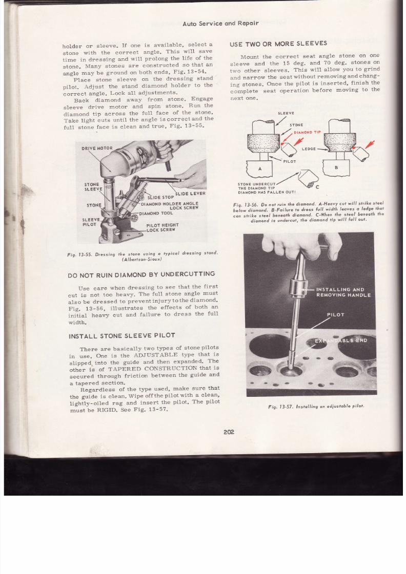
7/26/2019 Auto Service and Repair - Martin W. Stockel
http://slidepdf.com/reader/full/auto-service-and-repair-martin-w-stockel 202/224
Auto
Service
ond
RePoir
hoLder
or
s leeve.
If
one
is
avai lable,
select
a
stone
with
the correct
angle.
This
wil l
save
time
in dressing
and
will
prolong
the
life
of
th e
stone.
Many
stones
are
constructed
so
that an
angle
may
be
ground on
both
ends,
Fig' 13-54'
Place
stone
sleeve
on
the
dressing
stand
pilot.
Adjust
the
stand
diamond
holder
to the
corect
angle.
Lock al l
adjustments '
Back
diamond
away
from
stone'
Engage
sleeve
drive
motor
and
spin
stone'
Run the
diamond
tip across
the
full
face
of
the
stone'
Take
l ight
cuts
unt i l
the
angle
is
correct
and the
fu1l
stone
Jace
is c lean
and
true,
Fig '
13-55
DRIYE
MOTOR
STONE
SL E
IDE
STOP
DIAMOND
OLDER
NGLE
LOCK
SCREW
DIAMOND
OOL
5LE
EY E
PILOT
PILOT
HEIGHT
LOCK
SCREW
USETWO
OR
MORE
LEEVE5
Mount
the correct
seat
angle
stone
on
on e
sleeve
and
the
15
deg.
and
70
deg.
stones
on
two
other
sleeves,
This
wil l a11ow
you to
grind
and
narrow
the
seat
without
removing
and
chang-
ing stones.
Once
the
pilot
is inserted,
f inish
th e
complete seat operat ion before moving to th e
next
one.
DIAMOND
AS
ALLEN
OUTI
Fig.
I3-56,
Do
not
ruin
the dionond'
A'Heovy
cul
wi l l
st¡ ike sleei
buíon
dio^ond.
B'Foilure
to
dress
lu l t
width
leoves
o
ledge
thot
con
srr ike
steel
beneoth
diamond.
C-When
he steel
beneoth
he
dionond
s undercut,
he dionond
tip
wí l l
Ío l l
out '
F ig.
13-55.
Dressing
fhe slone
usíng
o typícol
dressing
slond'
-
(Albe¡fson-Sioux)
DONOT
RUIN
DIAMOND
Y
UNDERCUTTING
Use eare
when
dressing
to
see
that
the
f i rs t
cut
is
not
too
heavy.
The ful1
stone
angle
must
also
be
dressed
to
prevent in jurytothe
diamond'
Fig. 13-56,
i l lust rates
the
effects
of
both
an
init ial
heavy
cut
and
failure
to
dress
the
full
width.
INSTALL
STONE
SLEEVE
PILOT
There
are
basically
two
types
of
stonepilots
in use.
One
is
the
ADJUSTABLE
tlpe
that
is
slipped,
into
the guide and then expanded' Th e
other
ís
of
TAPERED
CONSTRUCTION
that
is
secured
through
frict ion
between
the
guide
an d
a
tapered
sect ion.
Regardless
of
the
type
used,
make
sure
that
the
guide
is clean.
Wipe
off
the
pilot
with
a clean'
üghify-oiled
rag
and
insert
the
pilot.
The
pilot
must
be
RIGID.
See
Fig. 13-57.
20?
Fig.
l3-57'
lnstal l ing
on
odiustoble
pilot '
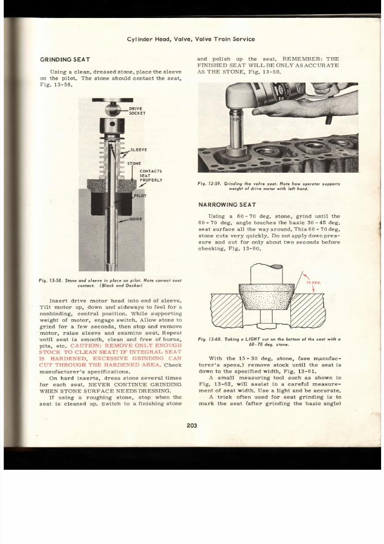
7/26/2019 Auto Service and Repair - Martin W. Stockel
http://slidepdf.com/reader/full/auto-service-and-repair-martin-w-stockel 203/224
Cylinder
Heod,
olve,
GRINDING
EAT
Using a
clean,
dressed stone,
place
the sleeve
on the
pilot.
The
stone should
contact
the
seat,
Fig.13-58.
Vqlve Trqin Service
and
pol ish
up the
seat.
REMEMBER:
THE
FINISHED
SEAT WILL
BE ONLY
AS ACCURATE
AS THE
STONE,
Fig.
13-59.
Fig.
l3-59.
Grinding
the volve
seof. Nofe how operotor upports
weight
o drive moto¡wirh
leÍt
hond.
NARROWING
EAT
Using
a
60
-
70 deg. stone,
grind
until the
60
-
70
deg. angle touches the
basic
30
-
45 deg.
seat surface all the way around.
This
60
-
?0
deg.
stone
cuts very
quiekly. Do
not applydownpres-
sure
and
cut
for
only about two seconds before
checking,
Fig.
13-60.
Fig. 13-60. Toking o LIGHT cut on ff ie boflom of t f ie seot with o
60-70 dea. stone.
With
the
15
-
30 deg.
stone,
see
mgnufac-
turerrs
spees.) remove stock until the seat is
down
to
the
speci f ied
width, F ig.
13-61.
A small measuring tool
such
as shown
in
Fig.
13-62,
wi l l
assist
in
a
carefu l
measure-
ment
of seat
width.
Use a l ight and be aecurate.
A triek often used
for
seat
grinding
is
to
mark the
seat
after
grinding
the basic angle)
*ñr,
CONTACTS
SEAT
PROP RLY
Fig.
l3-58,
Sfone
ond
s/eeve
in
ploce
on
pilot, Note
correct
seol
contocf.
Black
ond
Decker)
Insert
drive
motor head
into
end of sleeve.
Tilt
motor up, down and
sideways
to feel
for
a
nonbinding, central
posit ion.
While
support ing
weight of motor, engage switch.
AIIow
stone
to
grind for
a few seconds, then stop
and
remove
motor, raise sleeve and examine
seat. Repeat
unti l seat is smooth, clean and free of burns,
pits,
etc.
CAUTION:
REMOVE
ONLY
ENOUGH
STOCK
TO
CLEAN SEATJ
IF
INTEGRAL SEAT
IS HARDENED,
EXCESSIVE GRINDING
CA N
CUT
THROUGH THE HARDENED
AREA.
ChCCK
manufacturerrs specif icat ions.
On
hard
inserts, dress stone several
t imes
for
each seat.
NEVER CONTINUE
GRINDING
WHEN STONE SURFACE
NEEDS DRESSING,
If
using a
roughing stone,
stop when
th e
seat
is cleaned up.
Switch
to a f inishing stone
I
203
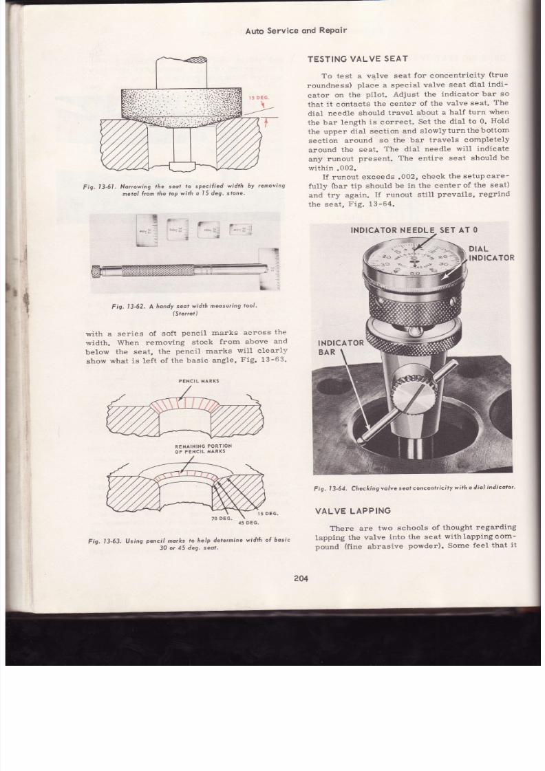
7/26/2019 Auto Service and Repair - Martin W. Stockel
http://slidepdf.com/reader/full/auto-service-and-repair-martin-w-stockel 204/224
Auto
Service ond
RePoir
F
s'
l3-61. Nonowíng
lhe seof
fo
specif ied
wídth
by removing
metol
l ron the
top
with o l5 deg.
stone.
F'
Fig.
3-62.A
hondy
eotwidfh
meosur ing
oo/ '
(Storre¡)
with a
series
of soft
pencil marks
across
th e
r.vidth.
When
removing
stock
from
above
an d
below
the seat,
the
pencil marks
will clearly
show what is lef t of the basic angle, Fig. 13-63.
REMAINING
ORTION
OF PENCIL
MARKS
'15
DEG'
Fig.
l3-63.
lJsing
pencí l
morks
lo help
determine
width
o( bosic
30
o¡ 45
deg. seot .
TESTING
ALVE
SEAT
To test a
valve
seat
for
concentricity
(true
roundness)
place
a special
valve
seat
dial
indi-
cator
on
the
pilot. Adjust
the
indicator
bar
so
that
it
contacts
the center
of
the valve
seat.
Th e
dial
needle
should
travel about
a
half
turn
when
the bar length is correct. Set the dial to 0. Hold
the upper
dial sect ion
and
slowlyturnthebottom
section
around
so
the bar
travels completely
around
the
seat.
The dial
needle
wil l indicate
any
runout
present.
The
entire
seat
should
be
within.002.
If
runout
exceeds
.002,
check
the setup care-
ful1y
bar
t ip should
be in
the center
of
the
seat)
and
try again.
If
runout
st i l l
prevails, regrind
the
seat,
Fig.
13-64.
INDICATOR EEDLESET
AT O
F
ig.
I
3-64. Checkíngvolve
seof concentr ici ty
wi th
o diol
indicoto¡ '
VALVE LAPPING
There are
two
schools
of
thought
regarding
lapping
the
valve
into
the seat
withlappingcom-
pound
(f ine
abrasive
powder).
Some
feel that
i t
rX
lE6.
'_ f
'o -¡
' '1
ia
I
-¡
I G
|
-. i$
¡ :
bi . . :
&\
i¿
**3,i
. INDICATOR
INDICATOR
PENCIL MARKS
2U
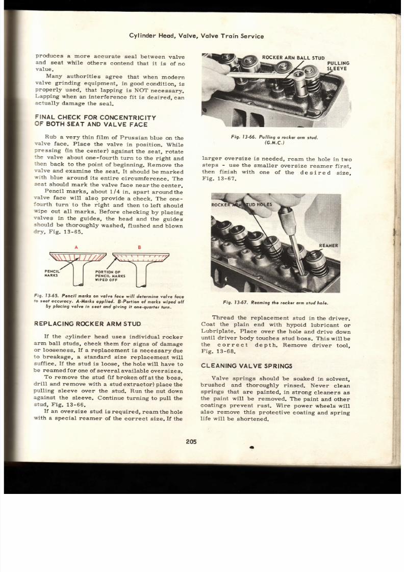
7/26/2019 Auto Service and Repair - Martin W. Stockel
http://slidepdf.com/reader/full/auto-service-and-repair-martin-w-stockel 205/224
Cylinder
Heod,
Volve,
Vqlve
Trqin
Service
produces
a more
accurate
seal
between
valve
and
seat while
others
contend
that
it is
of
no
value.
Many
authorit ies
agree
that
when
modern
valve grinding
equipment,
in
good
condit ion,
is
properly used, that lapping is NOT necessary.
Lapping
when
an interference
fit is
desired,
ca n
actually
damage
the
seal.
FINAL
CHECK
OR
CONCENTRICITY
OF
BOTH
SEAT
AND
VALVE
FACE
Rub
a very
thin
film
of
prussian
blue
on the
-;alve
face. Place
the
valve in
position.
While
pressing
(in
the
center)
against
the
seat,
rotate
:he
valve
about
one-fourth
turn
to the
right
and
:hen
back
to the
point
of beginning.
Remove
th e
-;alve
and
examine
the seat.
It
should
be marked
-¡ith
blue around its entire circumference. Th e
-<eat
should
mark
the
valve face
nearthecenter.
Pencil
marks,
about
1/4
in.
apart
aroundthe
;alve
faie
wil l
also
provide
a check. The
one-
lourth
turn
to
the right
and
then
to
left
should
iñ'ipe
out
all marks.
Before
checking
by
placing
'. 'alves in
the
guides,
the head
and
the
guides
should
be
thoroughly
washed,
f lushed
and
blown
:ry,
Fig.
13-65.
PENCI
MARKS
PORTION
OF
PENCIL
MARKS
WIPED
OF F
Fig.13-65,
Penci l
mo¡ks on volve
loce
wi l l dete¡mine
olve
foce
lo
seot
dccurocy.
A-Morks opplied.
B-Po¡¡ion al mo¡ks
wiped
ol l
by
placing
volve
in
seof ond
giving
i t one-quoder
utn.
REPLACING
OCKER RMSTUD
If
the
cylinder head
uses individual
rocker
arm
ball
studs,
check
them
for
signs
of damage
or
looseness. I f
a replacement
is
necessarydue
to breakage, a standard size replacement wil l
suff iee. I f
the
stud
is
loose,
the hole wil l
have to
be reamed
for
one of several
available
oversizes.
To
remove
the
stud
(if
brokenoff
atthe boss,
dri l l
and remove with
a studextractor)placethe
pulling
sleeve over
the
stud.
Run
the
nut down
against
the
sleeve. Continue
turning to
pull
the
stud, Fig.
13-66.
If
an
oversize
stud is
required,
reamthe
hole
with
a special
reamer
of the
correct
size.
If
th e
ROCKER
RM
BALL
STUD
PULLING
SLEEV E
Fig. l3-66.
Pulling
a rocke¡
orm
stud.
rc.M.C.)
Iarger
oversize
is needed,
ream
the
hole in
tw o
steps
-
use the
smal ler
overs ize
reamer
f i rs t ,
then
f in ish
with
one
of
the
desired
size,
Fig. 13-67.
Fig.
l3-67.
Reominghe
¡ocke¡o¡m
stud hole.
Thread
the
replacement
stud in
the driver.
Coat
the
plain
end with
hypoid
lubricant
or
Lubriplate.
Place
over
the hole
and
drive down
until
driver
body
touches
stud boss. This
wil lbe
the
correct
depth. Remove
dr iver
tool ,
Fig.13-68.
CLEANING
ALVE
SPRINGS
Valve
springs
should
be
soaked in
solvent,
brushed
and
thoroughly
rinsed.
Never
clean
springs
that
are
painted,
in strong
cleaners
as
the
paint
will
be
removed. The paint
and other
coatings
prevent
rust.
Wire power
wheels
wil l
also remove
this protect ive
coating and spring
life will
be
shortened.
¡
t:.
l1
ii
t
i*
li
1
$
t ,
] t
205
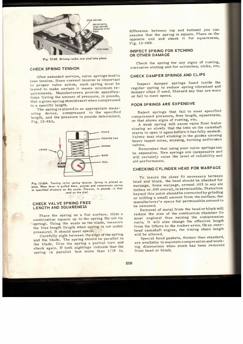
7/26/2019 Auto Service and Repair - Martin W. Stockel
http://slidepdf.com/reader/full/auto-service-and-repair-martin-w-stockel 206/224
STUD
RIVER
DRIVE
UNTIL
STUD
RIVER
ENGAGES
TU D
BOSS
Fig.
l3-68.
Driving
rocker
o¡m
stud
into
ploce'
CHECK
PRING
ENSION
After
extended
service,
valve
springstendto
lose
tension.
Since
correct
tension
is
important
to
proper
valve
action,
each
spring
must
be
tested
to
make
certain
i t
meets
minimum
re -
quirements.
Manufaeturers
provide
specifica-
tions
listing
the
amount
of
pressure,
in
pounds'
that
a
given
spring
should
exert
when
compressed
to
a
speeific
length.
The
spr ingisplacedin
an appropr iate meas-
uring
device,
compressed
to
the
specified
length,
and
the
pressure
in
pounds
determined'
Fig. 13-68A..
difference
between
top
and
bottom)
you
can
assume
that
the
spring
is square'
Place
on
th e
opposite
end
and
check
it
for
squareness'
F ig. 13-68B
INSPECT
SPRING
FOR
ETCFIING
OROTHERDAMAGE
Check
the
spring
for
any
signs
of
rusting'
corrosive
etching
and
for
scratches'
nicks'
etc'
CHECK
DAMPER
SPRINGS
AND
CLIPS
Inspect
damper
springs
(used
inside
th e
regular
spring
to
reduce
spring
vibration)
and
damper
clips
if used.
Discard
any
that
are
worn
or
fail
to
meet
sPecs.
POOR
SPRIN6
ARE
EXPENSIVE
Reject
springs
that
fail
to
meet
specif ied
compressed
pressure,
free
length,
squareness'
or
that
shows
signs
of
rusting,
etc'
A
weak
spring
will cause
valve
float
(valve
closing
so
slowly
that
the
lobe
on
the
camshaft
starts
to
open
it againbeforeithasfully
seated)'
Valves
may
start
sti.cking
in
the
guides
causing
heavy
tappet
noise,
missing,
burning
andbroken
valves.
Remember
that
using
poor valve
springs
can
be
expensive.
New
springs
are
inexpensive
an d
will certainly
raise
the
level
of
reliability
and
aid performance.
CHECKING
YLINDER
EAD
FOR
WARPAGE
To
insure
the
close
fit necessary
between
head
and
block.
the
head
should
be checked
fo r
warpage.
Some
warpage,
around
'003
in
any
si x
inches
or.006
overall,
is
permissible'
Distortion
beyond
this
point should
be conected
by
grinding
or
milling
a small
amount
from
the
surface'
See
manufacturerr
s
specs
for
permissible
amount
to
be
removed.
Removal
of
metal
from
the
headorblockwil l
reduce
the
size
of
the
combustion
cha'mber
(in
most
engines)
thus
raising
the
compression
ratio.
It
will
also
change
the
effective
length
from
the
lifters
to
the
rocker
arrns'
On an
over-
head
camshaft
engine,
the
timing
chain
length
wil l
be
altered.
Special
head
gaskets,
thicker
than
standard'
are
available
to
maintain
compression
and
work-
ing
dimensions
when
stock
has
been
removed
from
head
or
block.
206
LEVER
\\
sTt
D BOSS
SCALE
POINTER
PA D
SPRIN
BAS
DIAL
Fis. l3-684.
6ose,
When
to
specified
Testing
volve spring
tension'
Spring
ís
ploced on
lever
is
pul led down,
poinler
pod compresses
spttng
distonce
on tñe
scole.
Tension,
in
pounds.
is lhen
reod
on
¡he
d¡ol.
CHECK
ALVE
SPRING
REE
LENGTH
ND
SOUARENESS
Place the spring on a flat surface'' Slide
a
combination
square
up
to
the
spring
filo
not
tip
spring).
Using
the
scale
on
the
blade'
measure
ttre
t"ee
length
(length
when
spring
is
not
under
pressure) .
I t
should
meet
sPecs'
Carefully
sight
between
the
edge
ofthe
spring
and
the
blade.
The
spring
should
be
parallel
to
the
blade.
Give
the
spring
a
partial
turn
and
check
again.
If
both
sightings
indicate
that
the
spring
-is
parallel
(not
more
than
1/
16
in'

7/26/2019 Auto Service and Repair - Martin W. Stockel
http://slidepdf.com/reader/full/auto-service-and-repair-martin-w-stockel 207/224
VALVE
SPRING
COMBINATION
Fig. l3-688.
Checking
spring ree lengthond
sguoreness.
(Plymouth)
Fis.
l3-69.
Checkine
cyl i
:er
feld
surf lce
(o.r-worpose.
. - : ,
- .
Fig.
13-69, shows the use of a s tra ightedge
for
checking
cylinder
head surface
aceuracy.
Th e
straightedge
is
placed
across theheadas
shown.
Sight
along the edge to detect
any
warpage. If
any,
slide a
feeler
gauge
between
straightedge
and
head to determine the
amount.
Head
surface
rnust
also be
free
of nicks,
scratches,
gasket
:ement, etc .
INSTALL
NG
VALVES,
SEALS
AND
SPRINGASSEMBLIES
With the
cylinder
head
in a suitable fixture,
firead
must be
spotlessly
clean) oil
the valve
guides.
Select the
proper
valve, oil
the
stemand
insert into the guide.
On
engines
that do not have
provisions
for
adjust ing
rocker arm
to
push
rod
clearance,
the
height
of the valve stem from the head should be
checked.
In
that removal
of
metalfromthe valve
iace
and seat
wil l
al low
the
stem
to
protrude
further,
the rocker arm wil l be tipped down on
the
push
rod side, thus forcing the hydraulic
l i fter
plunger
near the bottom
of
its travel.
I f
orovisions are not built into the l i fter to adjust
Cylinder
Heod,Volve,
Vqlve
Trqin
Service
Fig.
l3-70.
Checkingolve
stem eight.
(Dodse)
to
this
change,
malfunctions
can
result.
I f
th e
height of the stem is excessive, the valve must
be
removed and the stem
end
ground
down the
proper
amount.
Check
al l valves,
Fig.13-70.
While
holding
the valve
in
place,
install stem
to
guide
oi l
seal ,
i f used. I frequired,
place
steel
washer
around
guide
and
in
contact
with head.
Place
spring
or
springs,
closed coil end
(one
end of the spring
may have
the
coils
spaced
closer
together
-
th is is
cal led
the
closed coi l
end) toward the head,
over
the
stem and
in
contact
with
the
head,
Fig.
13-71.
I f
dual
coi ls ,
or a
damper spr ing, are
used,
space
coi l
ends
per
manufacturerrs
instruct ions
(usually about 180 deg. apart).
Install
shield or umbrella and
retainer over
the
spr ing.
Using
a spr ing
compressor,
com-
press
the
spríng
just
far
enough
to expose the
stem oi l
seal
groove.
Sl ip the seal
into
the
RETAINER
SPRING
VALVE
CUP
SEAL
Fig. l3-71. Guide
seo/
(cup
seol)
instol led,
spring
ond
retainet
being
ploced
n
posi f ion.
(Chrysler)
207
{
MAXIMUM
MEASUREA4ENT
STRAIGHT
EDGE
odi, ;Do@.
[email protected] i . f f i .

7/26/2019 Auto Service and Repair - Martin W. Stockel
http://slidepdf.com/reader/full/auto-service-and-repair-martin-w-stockel 208/224
Auto
Service
ond
Repoir
groove.
Make
sure it is
properly
positioned
an d
is
not twis ted. Inser t
the spl i t keepers
or locks
and s1ow1y release
the spr ing. As
the spr ing
r ises,
guide
the retainer
soi t is
centeredaround
the keepers. When fu1ly
released,
checkkeepers
to
make
certa in they are
ful ly
engaged. iF
KEEPERS ARE NOT LOCKED INTO
POSITION,
THEY
CAN
SLIP
AND
FLY
OUT
WITH DAN-
GEROUS FORCE. KEEP
YOUR FACE TO ONE
SIDE,
Fig.
L3-72.
Fig.
I3-72,
Compressing
olve
spring
ond
nstol l ing sp/i t keepers.
Chevrole¡)
Each valve should be instal led in the port
from
which i t
was
removed unless
ei ther the
guide
or
valve
is
new. On
some engines
there
are
differences
between
intake
and exhaust
springs
and retainers.
Be
careful to
assemble
them in
the
proper
locat ions. Fig.
13-?3,
shows
a tlpical
valve
stem
assemblv. Note
the stem
SCAI.
TESTSTEM
SEAL
When
a stem
seal i.s
employed,
i t may
be
tested
by
placing
a small
suction
cup
over the
retainer.
Squeeze
the bulb while
holding
the
cu p
against
the
sssembly. When
the bulb is
released,
it
should stay
compressed thus
indicating
an
airtight
seal.
Such
a test
tool
is
shown
in
Fig.13-?4.
F¡s.
CHECKING
OF
VALVE
13-74. Yalv e sfem seo/ lesf fool.
Chev¡olet)
INSTALLEDHEIGHT
SPRING
As with the
valve stem
end, removal of
stock from
valve
faee
and
seat
wil l
al low the
keeper
grooves
to
protrude
higher
above the
head. This
wil l increase
the installed
length of
the spring, thus reducing
spring tension. Using
specs, measure
the
installed
height
of each
spr ing,
Fig.
13-75.
I f
the height is
excessive, i t must be
cor-
rected by
removing the
spring,
.and
placing
a
special s teel
washer
or
inser tbetweenthe
spr ing
and
the head. These
washers
are
available
in
different thicknesses. Donot install washers
that
are too thick,
as the spring
pressure
ean
be in-
creased
to the
point
of
causing
rapid
lifter
an d
camshaft
wear. Fig.
13-76, i l lustrates
one
type
of
washer used
to compensate
for
excessive
stem
length.
INSTALL¡NGCYLINDERHEAD
When the ball
joint
rocker
arms are used,
the rockers may
be attached
loosely to the
rocker
studs and left in this
position
while
the
head is installed.
Generally
the
roeker
shaft and
arm
assembly
is
installed
after the head is
in
position
and
has
been torqued.
ig. l3-73.
Typicol
volve
spring ossembly.
208
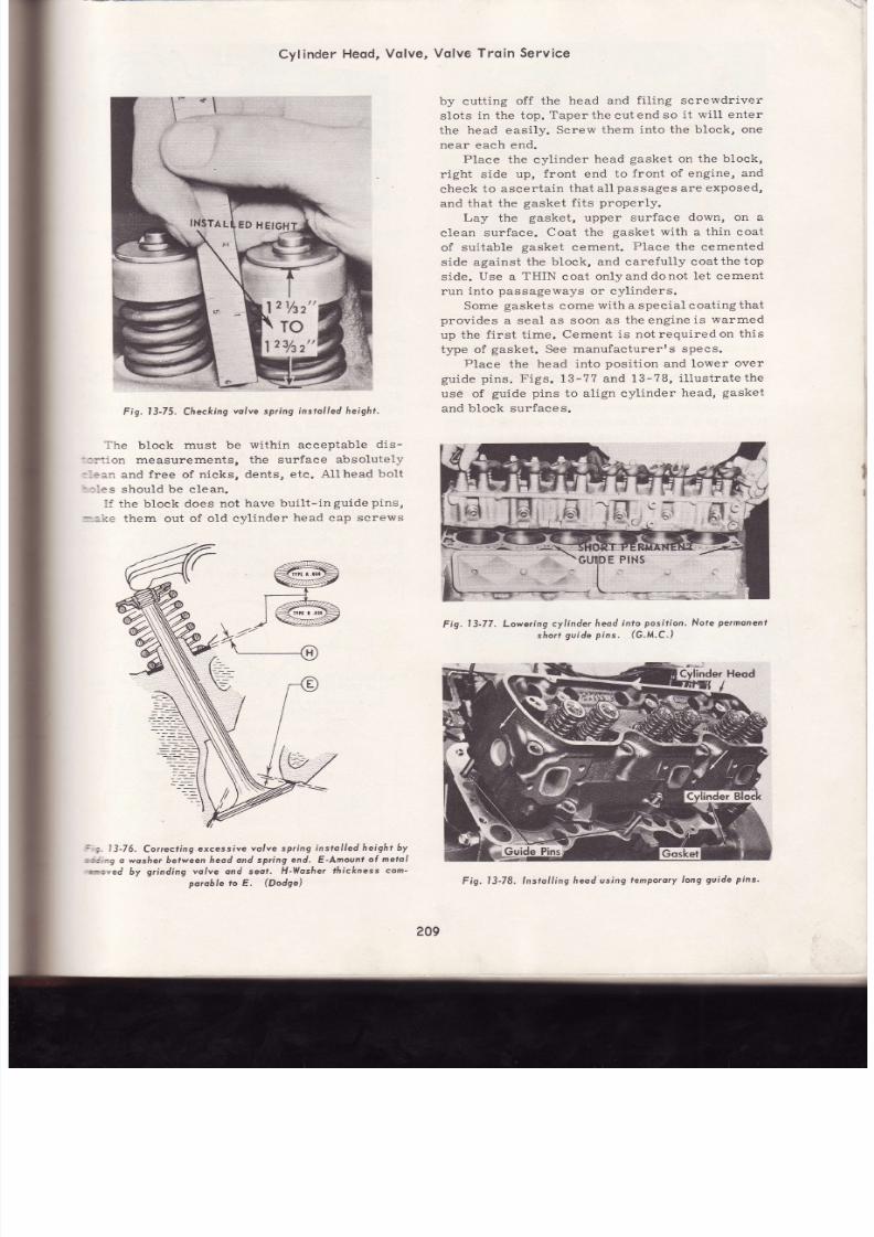
7/26/2019 Auto Service and Repair - Martin W. Stockel
http://slidepdf.com/reader/full/auto-service-and-repair-martin-w-stockel 209/224
.-
Cyl inder
Heod,
Volve,
Volve Trqin S ervice
by
cutting
off the
head and
fi.l ing
screwdriver
slots
in
the top.
Taper the
cut
end so
it wil l enter
the head easily.
Screw
them into
the block, one
near
each
end.
Place
the cylinder
head
gasket
on
the block,
r ight
side
up,
front
end
to
front
of
engine, and
check to ascer ta in
that
al l
passages
are
exposed,
and that the
gasket
f i ts
properly.
Lay
the
gasket,
upper
surface
down, on a
clean
surface.
Coat the
gasket with
a
thin coat
of
suitable
gasket
cement.
Place
the
cemented
side
against
the block, and carefully coatthetop
side.
Use
a
THIN
coat
onlyanddonot
let cement
run
into
passageways
or cylinders.
Some
gaskets
come
with a special coating
that
provides
a seal
as soon as
the engine
is
warmed
up
the
first
t ime.
Cement
is not required
on this
type of
gasket.
See
manufacturerrs specs.
Place
the
head into
position
and lower
over
guide
pins. Figs.
13-7?
and 13-?8,
i l lustratethe
usé of
guide pins
to align cylinder
head,
gasket
and
block surfaces.
Fig.
l3-75.
Checking
olve
spring
nstolled eight.
The
block
must be
within acceptable
dis-
: : : :on
measurements,
the surface
absolutely
:, :an
and
free
of
nicks, dents,
etc . A l lhead
bolt
- : les
should
be c lean.
If the block does
not
have
built- in
guide
pins,
:--:.ke
them out
of old cvlinder
head cap screws
Fig.
l3-77. Lowering
cyl inder
heod
n¡o
posi l ion. Nofe
permonenf
shon
guide
pins.
(G.M.C.)
=
i.
l3-76.
Correcl ing.excessíve
olve spring
nstol led
height by
r:,: ing
o wosñe¡6efween
heod ond spring
end.
E Amount
ol
metol
moved
by
grinding volve ond
seot.
H-Wosher
fr ickness
com-
poroble o
E.
(Dodge)
209
Fig.
l3-78. lnstol l ing
heodusing
lemPoroty
ong
gvide
pins.

7/26/2019 Auto Service and Repair - Martin W. Stockel
http://slidepdf.com/reader/full/auto-service-and-repair-martin-w-stockel 210/224
Coat
the
head
cap
screw
threads
(after
wire
brushing)
with
a
suitable
thread compound.
The
compound
should
have
the necessary
sealing
properties, especially
when
cap
screws.thread
into a
hole
that
enters
the
water.jacket.
Insert
the cap
screws
in their
proper lo-
cations,
(watch
for different
lengths).
I f
one of
the
eap
screws
is designed
to
pass
oil
from the
block
through
the
head to the
rocker assembly,
be
certain
it is
placed
in the correct
spot.
Run all
bolts down
until they
just
engage
the
head.
Remove
guide pins
and
install
bolts
in
these
holes.
TOROUE
EAD
BOLTS
Using a
torque
wrench and
following
the
recommended
sequence,
bring all bolts
up to
one
third
torque.
Go over them
againbringingto
two
thirds
torque.
They
should
then
be brought
to
full
torque.
A fourth time over
will make
sure
none
have been
missed.
Remember that
proper
torque
is
a
MUST.
Excessive
or
uneventighten-
ing
wil l distort cylinders,
valve
guides
andvalve
seats,
Fig.
13-79.
Fig.
I3-79. Tor.-qu.
od cop screws
in
proper
seguence.
ROCKERARM AND SHAFTSERVICE
Clean
each
rocker arm
shaft.
Pay
speeial
attention
to the
hollow
center.
Examine
for signs
of
wear and scoring.
Replace
if necessary.
Check
the condition
of
the rocker-arm-to-
shaft bearing
surface.
Ifbushings
are used,
wear
can
be corrected
byrebushing
andhoningto
s ize.
Fig.
l3-81.
Grinding
ocke¡
orm end.
Remove
o more toc/<
hon
absolutely
ecessory:
(Al6errson-Sioux,l
Excessive rocker-arm-to=shaft
clearance
will.
permit
a
heavy flow of oil
that could
flood
valve
stems and
increase
oil
consumption.
GRIND
ROCKER
ARM
The
rocker
arm valve
stem
end
should
be
ground to
a
smooth
even curve.
Using
a
valve
grinder,
mount the
rocker arrn
so the end
is
parallel to the
stone.
Adjust the swivel
attach-
ment
in such a
way that
the rocker
arm end
curve
wil l be maintained.
Dress the
wheel.
With
one
hand operating
the swivel
arm, andthe
other
holding the rocker
arm against
the
stone,
we t
grind
unti l the
surface
is
clean
andtrue.
Remove
no
more stock than
necessary,
Fig.
13-81.
Check
the
push
rod end of the
rocker.
On
th e
nonadjustable
versions,
there
wiLl b e a swivel
pocket in the end.
It must be smooth
and
free
from
gall ing.
When
an adjusting
screw
is
pro-
v ided, check
the bal l ,
Fig.
13-82.
ROCKER
ARM
TO
VALVE STEM PAD
ROCKER
RM
TO
SHAFT BEARING
PUSH
RO D
SOCKET
PUSH
RODBALL
EN D
ROCKERPUSHRODBALL
PUSHRODSOCKET
EN D
Fig.
13-82. Check
rocker
o¡m
sockef
on d
srnootñ
ond f¡ee of excessive
6ol l . Tfiese
must
weor.
210
be

7/26/2019 Auto Service and Repair - Martin W. Stockel
http://slidepdf.com/reader/full/auto-service-and-repair-martin-w-stockel 211/224
INSPECT PUSH
RODS
Push
rods
should be
straight
and both
ends
must
be
smooth.
If
the
push
rod
is
designed
to
carry
oil through
the
hollow
section,
be
certain
to
clean
the
inside
and
blow
dry.
INDICATOR
Fig.
l3-83.
Checking
ush
od
sfroighrness
ith
V-blocks n¿o
diol indicotor.
Rod
straightness
can
be
checked with V-
blocks
and
a
dial
indicator.
Maximum
allowable
runout
wil l
vary. See
specs.
See
Fig.
13-83.
MECHANICAL
IFTERS
RTAPPETS
Clean
lifter. Inspeet
push
rod
socket for
signs
of wear
or
gall ing.
The
lifter-to-camshaft
sur-
face
should be
smooth
and
free
of
cam
wear,
grooving,
chipping
and
gall ing,
Lifters
showing
heavy
camshaft
wear
or
worn
sockets,
shouldbe
replaced.
I f
the wear
is
minor,
the
tappet may
be
resurfaced
on the
valve
grinding
machine.
Li f ter
wear patterns
are shown in Fig.
13-84.
Tappet
adjusting
screws,
such as
shown in
F,
Fig.
13-84, may
also be resur facedprovid ing
the
valve
stem has
not worn
below
the hardened
portion.
Fig. I 3-84. Lilter weor
potterns.
A,B,C,E,
-
Consha(t
end ol lil¡er.
D-Push rod
end ol I
i l ¡er.
F
-T
oppet
od u
st
ing screw
L-H
eod en
gi
ne).
Fig.
l3-85.
Resurfocingvolve
l i l ¡er
end.
(Yon
No¡mon)
GRINDING
MECHANICAL
LIFTERS
Dress
the wheel
surface.
Secure
the
l i f ter
in
the V-block holder. While applying a stream of
coolant
to
the
lifter
end,
advance
the
lifter
against
the
stone.
Cuts
should
not
exceed
.002.
Move
the
lifter
back
and forth
over
the
stone
surface.
Do
not
remove
any
more
stock
than
absolutely
necessary.
At
the
end
of the
last
cut,
continue
to
move
the
lifter
back
and forth
unti l
the
cutting
action
stops.
This
witl
produce
a
smooth
finish.
I f
both
ends
of the
l i f ter
are
adapt-
able
to
grinding,
reverse
and
repeat
the
process,
Fig.
13-85.
When
lifter
wear
is
pronounced,
or
gall ing
and
chipping
are present,
check
the
cam lobe b
carefully
as
they
may
also
be
damaged.
Overs ize
l i f ters
may
be
used
to
correct
l i f ter
to
bore
c learance.
When
clearance
exceeds
.005 -
.006,
replacement
is
necessary.
The
bores
should
be reamed
to the
exact
overs ize
needed.
SERVICING
YDRAULIC
LIFTERS
The portion
of the
l i f ter
body
that protrudes
below
the
guide
bore
is
often
coated with gum
and
varnish. This
make
s removal
diffi .cult
unle
ss
a
special
tool
is
used
to
grasp
the
lifter. The
tool
is
engaged
and
the
lifter pulled
upwardwith
a twis t ing
motion, Fig.
13-86.
KEEP
LIFTERS
N
ORDER
Each
l i f ter
should
be
placed
in
a marked
holder
so
i t
may
be
returned
to
the
guide
bore
from
which
it
was
removed.
Ablock
of wood
with
two
rows
of holes,
each
row
representing
on e
bank
of
l i fters,
wil l
do .
. I
@
L--/
,b
M
\J
ZA
t€-1
\-,J
GALLED
@
\-_-,
o.
K.
\^r/
?-
Zg,
f.---=- 1
\-^,
211

7/26/2019 Auto Service and Repair - Martin W. Stockel
http://slidepdf.com/reader/full/auto-service-and-repair-martin-w-stockel 212/224
Fig.13-86.
lJsíng o speciol
puller
to
remove
o
hydroulic
l iher
(c,M.c.)
DISASSEMBLING
IFTER
Place
the
lifter
body,
right
side
up,
on a clean
board.
Using a
push
rod,
depress
the
plunger
and snap
out
the
reta in ing
r ing,
F ig. 13-87.
Push
Rod
Fig.13-87. Removing
iher
plunger retoin ing
ing.
(Cheúrolet)
Release
pressure
on
the
plunger
and
guide
out of
l i f ter
body.
I f the
plunger st icks,
and
it
often
will, i t
may
be removed
with a
tool
de -
signed
for this
purpose.
One such
tool
operates
by
placing the lifter
body
in the
tool
and
then
striking
the
tooL,
plunger end
down,
against
a
block
of
wood.
KEEP
PARTS
OF
LIFTERS
OGETHER
Lif ter
parts
are
made
to extremely
close
tolerances
(.0001)
and
the
plunger
is select ively
f it ted
(several
plungers
tr ied
until
one
fits
perfectly)
to
the
body.
THE
PLUNGER
AND
LiFTER
BODY
ARE
NOT INTERCHANGEABLE
and
as such,
must
be kept together.
Fig.
13-87.A,
shows
a
disassembled
lif ter.
The
check
valve
retainer,
spring
and
valve
are
st i l1
in
place
on
the
plunger.
As
each
lif ter
is disassembled,
place the
parts
in
individual,
MARKED
traYs.
LIFTER
BODY
PLUNGER
SPRING
CHECK
VALVE
CAGE
OR RETAINER,
HOUSING
CHECK
VALVE
AND
SPRING
TAPPET
LUNGER
F s .
CLEAN¡NG
LIFTERS
A special
eleaning
stat ion,
such
as
shown
in
Fig. 13-88,
is desirable.
Note
the compartmented
tray
in
which l if ter
parts
are
kept together.
Th e
tray
on the
left contains
a
special
cleaning
solvent
designed
to dissolve
gum,
varnish,
etc.
The
central
tray eontains
clean
kerosene
fo r
212
Fig.
l3-88.
A
good
sefup
Íor c leoning
hydtoulic
votrve
i l ters

7/26/2019 Auto Service and Repair - Martin W. Stockel
http://slidepdf.com/reader/full/auto-service-and-repair-martin-w-stockel 213/224
Cylinder
Heqd,
Vqlve,
Vqlve
Troin
Service
:-nsing.
The
small
tray
contains
cleankerosene
i:r a
FINAL
rinse.
A clean
work
area
is also
::ov ided,
Fig.13-BB.
Due to
the
close
working
tolerances'
l i fters
:-:rst
be
THOROUGHLY
CLEANED
and
assem-
:led in a SPOTLESS CONDITION' The SLIGHT-
:ST
TRACE
of
gr i t ,
dust,
l int ,
etc ' ,
wi l l
cause
i=::1ty operation.
- \ f ter
alL
lifters
are
dismantled,
r inse
each
-oup
of
parts
in
clean
kerosene'
DO
NOT
US E
:rr¡
fnnOSENE
IN
THE
TRAYS'
This
first
: : : :se
is
merelyto
remove
most
of
the
oil '
s ludge'
: :c , ,
so
the
useful
l i fe
of
the
special
cleaning
-.¡h'ent
wil l
be
prolonged.
5OAK
N
SOLVENT
Following
the
initial
r inse,
plaee
the
tray
:n::h compartments intothe cleaning
solvent'
La y
:l:ngers
and
l i f ter
bodies
on
their
sides
so
th e
=olváni
will
enter.
Allow
to
soak
for
about
one
:: :ur .
Exact
soaking
t ime
wi l l
depend
onthetype
-i
solvent
used,
how
often
used,
and
condition
:i l i fters.
KEEP
HANDS
OUT
OF
CLEANING
:,')1-UTION
AND
AVOID
SPLASHING'
ITISWISE
:f USE
RUBBER
GLOVES
WHILE
CLEANING
-- :TERS.
\\rhen
the
soak
cycle
is completed'
elevate
the
::ay.
After
tipping
from
side
to
side
to
empty
:arts
of
solvent,
suspend
the
tray
over
the
:¡ lution
unti l
the
excess
solvent
hasdrippedoff'
RINSE
N
KEROSENE
When
thoroughly
drained'
place
tray
in
the
; n
of
initial
r inse
kerosene'
Agitate
the
tray
=ut . l
t imes
by
lift ing
and
lowering'
Remove
=::d
allow
to
drain.
This
rinse
wiLl
remove
the
:1.eaning
solvent
and
a
great
deal
oftheloosened
ieposi ts .
Wipe
all
l i f ter
surfaces
with
a
clean'
l int-
l:ee cioth.
Use
afirmwiping
actiontoremove
al l
:emaining
gum.
A
soft
bristle
brush
should
be
':sed
for
the
inside
of
the
lifter
and
plunger
':
odie
s.
When
all
lifters
have
been
cle-aned'
place
:he
tray
in the center container of kerosene'
-lgltate,
remove
and
allow
to
drain'
Blow
al l
;arts
drY.
INSPECT
IFTER
PARTS
(PLUNGER):
Use
a
magnifying
glass
to
in -
spect
plunger
check
valve'
seat
for
nicks'
seratches
and
wear.
Inspect
outer
plunger
body
ior signs
of
gall ing.
Any
scratches
on
eitherthe
check
seat
or
plunger
body
that
can
be
fel t
with
the
fingernail
are
cause
for
rejection'
Ignore
the
slight
edge
that
may
occur
where
the
p^lunger
ex-
ter 'r as
Ueyond
the
inner
working
surface
of
the
lifter
body.
However,
if this
edge
is
quite
sharp'
the
plunger
must
be
considered
defective'
(LIFTER
BODY):
Check
the
l i f terbodyinner
and
outer
surfaces.
They
must
be
smooth
an d
free
of
scoring.
The
lifter-to-eam
lobe
surface
must
also
be
smooth
andfree
of
gal l ing '
chipping
and
excessive
wear.
A
roundwearpattern
( l i f ter
was
rotating)
or
a
square
wear
pattern
( l i f ter
not
rotating)
as
long
as
the
pattern
is
smooth
and
free of
wear,
is accePtable'
The outer
portion
of
the
lifter
body
that
contacts
the
l i f ter
guide
bore
wil l
usually
show
a
distinct
wear
pattérn
caused
by
cam
load
side
thrust.
I t too,
unless
scored
or
pronounced'
ca n
be
considered
accePtable '
(PUSH
RoD
SEAT):
I f the push rod seat is
scored
or
badlY
worn,
rePlace'
(CHECK
BALL
OR
VALVE
DISC):
Examine
the
cheek
ball
with
the
magnifying
glass'
An y
nicks,
dents,
scratches,
etc',
wil l
render
i t
usele
s s .
(BALL
RETAINER):
The
ball
retainer
wil l
show
a
bright
spot
where
it contacts
the
check
ball.
This
is
normal.
A
pounded
area
or
an y
cracks
wi l l
be
cause
for
rejection'
(SPRINGS): Inspect
both
plunger
and
check
valve
springs
for
signs
of
distortion
or
other
damage.
RePlace
if
necessarY'
(p,t-UNCnn RETAINER RING): Diseard an y
retainer
rings
that
are
bent
out
of
shape'
REPLACING
PARTS
Some
garages
replace,
when
required'
the
push
rod
seat,
retainer
ring,
ball
retainer'
check
baII
or
disc
and
the
sPrings'
Other
garages,
when
any
part shows
damage'
discard
the
entire
assembly'
This
school
of
practice
employs
the
argument
(and
it
is a
good
one)
that
the
cost
of
new
lifters
is
small
com-
pared
to
that
of
a
possible
comeback
from
some
premature
lifter
faihrfe'
;i
There
are
also
garages
that
wil l ' whenthere
is
considerable
mileage
on
the
engine'
not
even
clean
and
inspect
the
tifters'
They
are
auto-
matically
discarded
in
favor
of
new
ones'
Dis-
assembly
and
cleaning
plus
inspection'
reasqem-
bLy
and
testing
take
some
time'
I f
the cost
of
this
labor
is
deducted
from
the
price
of
ne w
lifters,
plus
the
increased
reliabil i ty
faetor '
there
is
much
to
be
said
for
replacement'
213
I
I
,I
i
I
'i;
i '
i
s;
I
I
l
I
1
I
i
l1
I
I
l

7/26/2019 Auto Service and Repair - Martin W. Stockel
http://slidepdf.com/reader/full/auto-service-and-repair-martin-w-stockel 214/224
Auto
Service
ond
RePoir
INSPECT
ND
ASSEMBLE
NE
AT
A
TIME
After
all
the
parts of
one
lifter
have
been
inspected
and
where
required,
replaced,
they
should
be
rinsed
in the
central
tray
ofkerosene'
blown
dry
and
thenthoroughlyrinsedinthe
small
pan
of
kerosene.
Each
part,
as
it is
assembled,
must
be
put
through
this
sequenss.
One entire
lif ter
should
be
inspected
and
assembled
before
going
on
to
the next.
LIFTER
ASSEMBLY
With
the
plunger
held
vertically,
push
rod
seat
in
place, check
valve
seat
up,
place
th e
check
ball
or
check
disc
on
the seat.
Set
th e
check
valve
spring
over
the
valve.
Place the
valve
retainer
over
the spring
and
snap
down
into
plunger recess.
The
plunger spring
is
then
placed over
the
ball
retainer
and
the
lif ter
body
lowered
down
over
the
Plunger.
Turn the
lif ter
body
right
side
up,
dépress
the
push rod
seat
and
install
the
retainer
ring'
Wrap
assembly
in cLean,
slickpaper
andproceed
to the
next
l if ter.
ALL
LIFTER
PARTS SHOI ILD
BE ASSEMBLED WET WITHRINSE
KEROSENE.
DO
NOT
WIPE
OR
BLOW
DRY.
Figs.
13-89
and
13-90,
i l lust rate
two
typical
hydraulic
l if ter
assemblies.
One uses
a round
check
ball,
the
other
a
f lat check
disc.
Note
respective
Posit ion
of
all
Parts.
1
2
3
4
5
6
I
I
I
10
Pr¡sh
Rod
Oil Gallery
Lüter
Body
Camshaft
Valve
Spring
Plunger
Spriag
Yalve Ball
Plunger
Push
Rod
Se¿t
Reiainer
Ring
PUSH
RO D
Fig.
13-89.
Hydroulíc
i l ter
ut i l iz ing
o boll
check
volve'
PUSH
ROD
FORCES
AGAINSI
StIGHf
LEAKAGE
PASÍ
PIUNGER
VAI-VE
DISC
cr-osED
F¡g.
l3-90.
Hydrovlic
l i l te t
ut i l iz ing
o disc
check
volve'
-
(L incoln)
VALVE
DISC
214
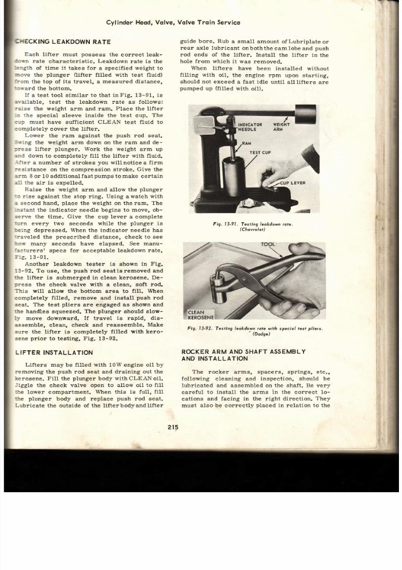
7/26/2019 Auto Service and Repair - Martin W. Stockel
http://slidepdf.com/reader/full/auto-service-and-repair-martin-w-stockel 215/224
Cylinder
Heod,
Volve,
EAKDOWN
ATE
Each
lifter must
possess
the
correct
leak-
rate
characteristic.
Leakdown
rate is the
of time it takes for
a specified
weight
to
the
plunger
(lifter
filled with test
fluid)
the top
of
its
travel, a
measured distance,
the bottom.
I f
a
test
tool s imi lar to that
in
Fig.
13-91, is
test the leakdown
rate
as
follows:
the
weight
arm and ram.
Place
the
lifter
special sleeve
inside the test
cup.
Th e
must have
sufficient CLEAN test fluid to
eover the
l i f ter .
Lower
the
ram against the
push
rod seat.
the
weight
arm down on the ram and
de-
l i f ter
plunger.
Work
the
weight
arm up
down to
completefy
fill
the lifter
with fLuid.
a number
of strokes
you wil lnotice
a
firm
on the
compresSion
stroke.
Give
the
or 10 additional
fast
pumps
to
make
certain
the
air is expelled.
Raise
the
wéight
arm and allow the
plunger
rise
against the stop r ing.
Using
awatch
with
second
hand,
place
the weight on the ram.
The
the indicator needle begins to move, o b-
the time. Give the
cup
lever
a complete
every
two
seconds
while
the
plunger
is
depressed. When the indicator needle has
the
prescribed
distanee, check
to see
many
seconds
have
elapsed.
See manu-
specs
for
acceptable
leakdown rate,
nother
leakdown tester
is
shown
in
Fig.
To
use, the
push
rod seatisremoved
and
l i f ter
is
submerged
in
elean
kerosene. De-
the
eheck valve
with
a
elean,
soft rod.
will
allow the
bottom area to
fill. When
filled,
remove and
install
push
rod
The
test
pliers
are engaged as
shown and
handles squeezed.
The
plunger
should slow-
downward.
If
travel
is
rapid,
dis-
clean, eheck
and reassemble.
Make
the l i fter is
eompletely
fi l led
with kero-
prior
to testing,
Fig.
13-92.
INSTALLATION
Lifters may
be
filled with
10Wengine
oil by
the
push
rod seat and draining out
the
Fil l
the
plunger
body
with
CLEAN oil.
the
check
valve open to allow oil
to fill
lower
eompartment.
When
this
is fu l l ,
f i l l
body and
replace
push
rod seat.
the outside of
the l i fterbodyandlifter
Vqlve Trqin Service
guide
bore.
Rub
a small amount
of
Lubriplate
or
rear axle lubricant
onboththe
camlobe and
push
rod en ds of the
lifter. Install
the
lifter in the
hole
from which
it was removed.
When l ifters
have
been installed
without
fi l l ing
with
oil, the
engine rpm
upon
starting,
should
not
exceed
a
fast idle
unti l
al l l i fters
are
pumped up (fi l1ed with oil) .
Fig.
l3-91.
Testing
leokdown
rote.
(Chevrolet)
Fig.
l3-92.
Tesfing leokdown ¡ote
wi th speciol test
p/iers.
'
(Dodse)
ROCKER
ARM AND SHAFT
ASSEMBLY
AND INSTALLATION
The rocker
arms,
spacers, springs, etc.,
fol lowing
cleaning and
inspection, should be
lubricated and
assembled on
the shaft. Be
very
careful
to
install
the arms
in
the correct Io-
cations
and
facing in
the
right direction.
They
must
also be
correctly
placed
in relation to the
I¡
.
j * ' ,
1.
l ,
I
, i :
j ,
i ',,
l r
] ' .
i :
i
i r
I
I
I
i, ,
ll
INDTCATOR
215
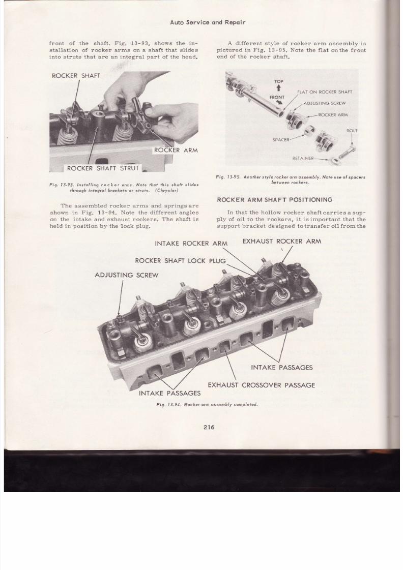
7/26/2019 Auto Service and Repair - Martin W. Stockel
http://slidepdf.com/reader/full/auto-service-and-repair-martin-w-stockel 216/224
Auto
Service
ond
Repoir
f ront
of
the shaft.
Fig.
13
I3,
shows the
in-
stal lat ion of rocker arms
on
a shaf t
that s l ides
ínto
st ruts
that
are an
integral
part
of
the head.
Fig, l3-93, lnstol l íng
rocke¡
qrms.
Noie
¡ho¡ ¡his
shoft sl ides
through integral b¡ockets
or sf¡uis.
(Chrysler)
The
assembled rocker arms and
spr ings are
shown
in
Fig.
13-94.
Note
the
dif ferent
angles
on the intake and exhaust rockers.
The shaf t
is
held in
posi t lon
by the lock
plug.
ADJUSTING
CREW
I d i f fe rcn t s fw le
6f
n ja+,,¡aA
j-
Fjx 12-95.
Y'v
L ur
end of the rocker
shaft.
rocker arm
assembly
is
Note
the f lat
onthe
front
FIAT ON ROCKTR HAFT
AR M
30rT
I
I
*
./,
RÉTAINTR:*
.
\
F ig, I 3-95, Anothe¡ sty le rockerorm ssem6/y.Note use of spocers
between ockets,
ROCKER
ARM SHAFT
POSITIONING
In
that the
hol low
rocker
shaft
carr ies
a sup-
nlv nf n j l tn thc rnnkers
i f
rs
imnorfnnf
that the
support bracket designed
tot ransfer oi l f romthe
INTAKE
ROCKER
RM
EXHAUST OCKER RM
ROCKER
HAFT OCKPLUG
*,
.
ROCKERSHAFT
ROCKER
HAFT
TRUT
*
W;*o'o'*
*u*
, a--
sPqcER-/
,* Éa
INTAKE
PASSAGES
EXHAUST
ROSSOVERASSAGE
INTAKEPASSAGES
Fig.
l3-94.
Rocker
orm
ossembly
comp/efed.
216
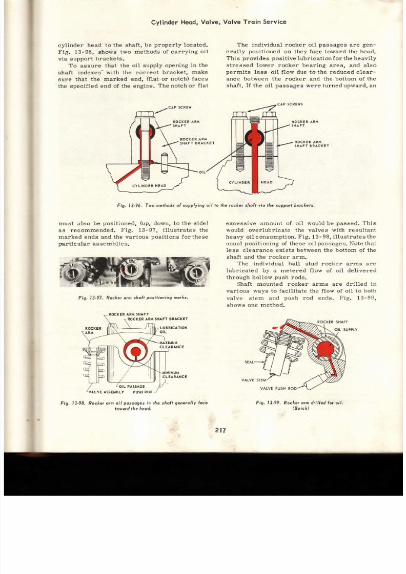
7/26/2019 Auto Service and Repair - Martin W. Stockel
http://slidepdf.com/reader/full/auto-service-and-repair-martin-w-stockel 217/224
fr
cylinder
head to the shaft,
be
properly
located.
Fig.
13-96,
shows two
methods of carry ing
oi l
via
support
brackets.
To
assure
that
the oil supply
opening
in the
shaft
indexes-
with the
correct
bracket,
make
sure
that
the marked end,
flat
or notch)
faces
the
specif ied
end of the engine.
The
notch or
f lat
CAP SCREW
ROCKERAR M
SHAFT
Cylinder
Heod,
Volve,
Volve Troin
Service
ROCKER
AR M
SHAFT
BRACKET
The individual rocker
oil
passages
are
gen-
erally
posit ioned
so they
face
toward the
head.
This
provides posit ive
lubricat ion
for
the
heavily
st ressed lower rocker bear ing area,
and
also
permits
less oi l
f low
due to the reduced
clear-
ance between the rocker
and the
bottom
of
th e
shaf t .
I f
the oi l
passages wereturnedupward,
an
cAP SCREWS
ROCKER ARM
SHAFT
ROCK
R ARM
SHAFT
BRACKET
excessive
amount
of oi l would be
passed.
This
would
overlubricate
the
valves
with
resultant
heavy oiL
consumpt ion.
Fig.
13-98,
i l lust rates the
usual
posi t íoning
of these oi l
passages. Note
that
less c learance exists between the
bot tom
of the
shaft and the rocker arm.
The individual ball
stud rocker arms are
lubricated by a metered flow of oi1 delivered
through hollow
push
rods.
Shaft
mounted
rocker arms are
dril led
in
various
ways to
facil i tate
the
f low
of oil to both
valve
stem and
push
rod ends.
Fig.
13-99,
shows
one
method.
l3-99.
Rockerorm dri l led {or o i l .
Buick)
Fig. 13-96. Two
methodso
supplying oi l to the rocker shoÍt vío
fhe
supporf
brockets.
must also be
posit ioned,
up,
down, to the side)
as
recornmended.
Fig.
13-9?,
i l lust rates the
marked ends and the various
posit ions
forthese
pa.rt icular
assemblies.
Fig.
l3-97.
Rocker
orm sholt
posil ioning
morks.
ROCKER
RM
SHAFT
ROCKER RM
SHAFTBRACKET
LUBRICATION
ot L
MAXIMUM
CLEARANCE
MINIMUM
CLEARANCE
ROCKER
AR M
OIL PASSAGE
ALVE ASSEMBLY
PUSH
RO D
Fig.
l3-98, Rocke¡
orm oil
possoges
n the sholt
generol ly
loce
toword
¡he heod.
CYLINDER
HEAD
217
Fís.
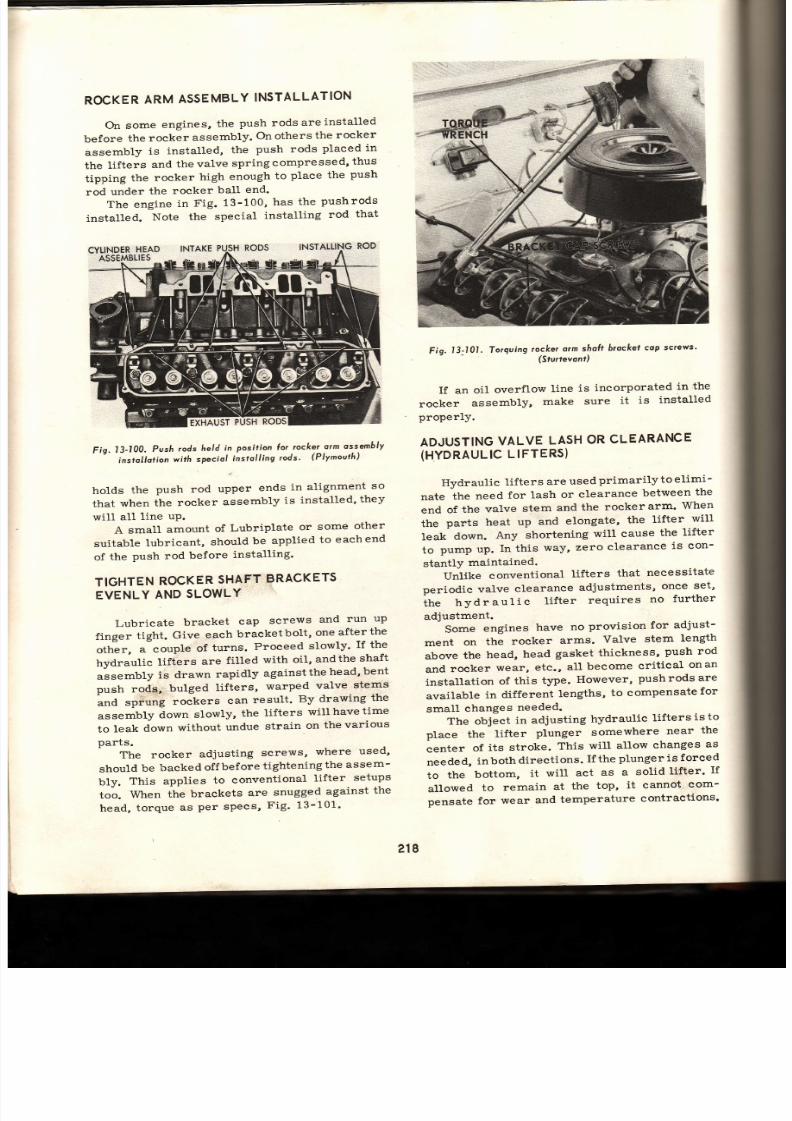
7/26/2019 Auto Service and Repair - Martin W. Stockel
http://slidepdf.com/reader/full/auto-service-and-repair-martin-w-stockel 218/224
ROCKER
RM
ASSEMBLY
NSTALLATION
On some
engines,
the
push rodsareinstalled
before
the
rocker
assembly.
On others
the
rocker
assembly
is
installed,
the
push rods
placed
in
the
lifters
and
thevalve
springcompressed,
thus
tipping the rocker high enough to plaee the push
rod
under
the
rocker
ball
end.
The engine
in
Fig.
13-100,
has
the
pushrods
installed.
Note
the
special
installing
rod
that
Fíg,13-100'
vsh
ods
held
n
posifion o¡
.rocke¡
rm
ossembly
installotion
wit[
specíol
nstolling
rods'
(Plynourh)
holds
the
push rod
lrOO
ends
in
alignment
so
that
when
the
rocker
assembly
is
installed'
they
will
all
line
uP.
A small amount of Lubriplate or some other
suitable
lubricant,
should
be
applied
to
each
end
of
the
push rod
before
installing'
TIGHTEN
OCKER
HAFT
RACKETS
EVENLY
AND
SLOWLY
Lubrieate
bracket
cap
screws
and
run
up
finger
tight,
Give
each
bracket
bolt,
one
after
the
oth er,
a couple
of
turns.
Proceed
slowly'
If the
hydraulic
lifiers
are
filled
with
oil,
andthe
shaft
assembty
is
drawn
rapidly
againstthe
head'
bent
oush
rodq;
bulged
lifters,
warped
valve
stems
rra
sp*urrg rockers can result. By drawing the
assembly
áown
slowly,
the
lifters
willhavetime
to
leak
down
without
undue
strain
on
the
various
parts.
The
rocker
adjusting
screws,
where
used'
should
be
backed
off
before
tightening
the
assem-
bly.
This
applies
to conventional
lifter
setups
too.
When
the
brackets
are
snugged
against
the
head,
torque
as
per specs,
F ig. 13-101'
Fig. 13-101. Torquing ¡ocke¡ arm shoft brocftet cop screws'
(Stu¡revont)
If an
oil
overflow
line
is
incorporated
in
the
rocker
assembly,
make
sure
it
is
installed
properIY.
ADJUSTING
ALVE
LASH
OR
CLEARANCE
(HYDRAULIC
IFTERS)
Hydraulic
lifters
are
used
primarily
to eLimi-
nate
the
need
for lash
or
clearance
between
the
end
of
the
valve
stem
and
the
rocker
arm'
When
the parts heat up
and
elongate,
the
lifter
will
leak
down.
Any
shortening
will cause
the
lifter
to
pump
up.
In this
way,
zero
clearance
is con-
stantly
maintained.
Unfite
conventional
lifters
that
necessitate
periodic
valve
clearance
adiustments,
once
set'
i t ru
hydraul ic
l i f ter
requi res
no
further
adjustment.
Some
engines
have
no
provision
for
adjust-
ment
on
the
rocker
arms.
VaLve
stem
length
above
the
head,
head
gasket
thickness,
push
rod
and
rocker
wear,
etc.,
all
become
crit ical
onan
installation
of
this
type.
However,
pushrods
are
available
in different
lengths,
to compensate
for
small
ehanges
needed.
The object
in adjusting
hydraulie
lifters
isto
place
the
lifter
plunger
somewhere
near
the
center
of
its
stroke.
This
will allow
changes
as
needed,
inboth
directions.
Ifthe
plunger
is forced
to
the
bottom,
it
will
act
as
a
solíd
lifter'
If
allowed
to
remain
at
the
top,
it cannot
com-
pensate
for
wear
and
temperature
contractions'
218

7/26/2019 Auto Service and Repair - Martin W. Stockel
http://slidepdf.com/reader/full/auto-service-and-repair-martin-w-stockel 219/224
LIFTER
MUST
E
ONCAM
LOBE
BASE
CIRCLE
Rotate
the
engine
unti l
the
cam
lobe
nose
jaees
directly
away from
the
lifter.
The
lifter
-nrl l
then
rest
on the
base
circle.
There
are
several
ways
of determiningwhen
:he
lobe
is
in
this
position.
On
some
engines,
such
as
the
overhead
eamshaft
type,
the
lobe
is
-isible.
I f
the
engine
is
inthe
car
and
the
ignition
:s properly
timed,
the
engine
can be
slowly
::lrned
over
unti l
the plug
lead
to the
cylinder
:oncerned,
fires.
At
this
instant,
bothvalves
ar e
:losed
and
the
lobes
are
in
the
proper
position
jor
Iash
setting.
By
slowly
eranking
the
engine
unti l
a
particu-
lar
valve
is
fully
opened
and
then giving
the
aRANKSHAFT
exactly
one
full
turn
(mark
jamper
with
chalk)
the
cam
lobe
wil l
be
turned
rne-half
revolution
thus
placing
the
lobe
nose
ryposite
the lifter.
When
a
piston
is
brought
to TDC
(top
dead
:enter)
on
the
compression
stroke
(both
valves
:iosed)
the
lobes
are in
the
correct position
fo r
: iat
cylinder.
- {nother
technique
involves
div id ing
the
l=.mper,
with
chalk
marks,
into
three
120
deg.
sections
(six
cylinder),
or four
g0
deg.
sections
-;-8).
One
of
the
marks
is
on
the timing
notch,
:-:-d
the
others
are related
in
degrees,
to
this
* rk.
By
cranking
the
engine,
in
various
se _
::ences,
unti l
the
marks
index
with
the
timing
;cinter,
it
is possible
to
set
certain
valves
an d
:l:¡s reduce the amount of eranking required,
- :g.13-102.
TIFTER
PLUNGER
UST E
AT
TOP
OF
TRAVEL
The
rocker
arm
adjustment
should
be
l:osened
so the
lifter plunger
travels
to the
to p
¡j its
stroke.
At
this
point,
the
push
rod
can be
':ggled
sideways
and upanddown,
Fig.
13-103.
Grasp
the
push
rod
concerned
withthethumb
:nd
forefingers.
While
genily
shaking
it
side-
rrays,
slowly
tighten
the
rocker
arm
adjustment.
-r-s he rocker arm push rod end moves down-
¡ard,
the
amount
of
shake will
be reduced.
Stop
::
the
instant
all
play
or shake
is
gone.
At this
;oint
the
lifter
is
resting
onthe
cambase
circle,
:b.e
plunger
is
at
the top
of its
travel,
and
no
lash
is
present
between
valve
stem
and
rocker
:r
rocker
and
push
rod.
Following
manufacturerts
specs, give
th e
LIFTER-
Fig. l3-102.
7o
ser
volve
/os[
on t/re
cq m
ROCKER
AR M
PUSH
RO D
CAM
BASE
CIRCLE
CAMSHA
T
-
CAM FLANK
CAM
NOSE
or
cleoronce,
the
l i l te¡
must
rest
6ose
circ/e.
ADJUSTING
UT
=l
'l
tr+
rl
{
PLUNGER
STOP
RING
LIFTER
BODY
PLUNGER
EALL
CAGE
PLUNGER
SPRING
CAM
BASE
CIRCLE
CAA.TSHAFT
Fig.
I3-103.
Hydraul ic
I i l ter
plunger
ogoinsf
fhe
stop r ing,
rock-
er o¡m
bocked ofi
un¡il push
rod
sáoke is evident.
rocker
arm
adjustment
an
additional
number
of
turns
(1
-1/Z
typical).
This
wi l l forcetheplunger
down
to
the
midpoint
of its
stroke
ortravel.
Re -
ROCKER
STUD
219

7/26/2019 Auto Service and Repair - Martin W. Stockel
http://slidepdf.com/reader/full/auto-service-and-repair-martin-w-stockel 220/224
-- 1
s{
rk
i \
ROD
Fig.13J04,
Removing
pusá
rod shoke
prior to
l inol
odiuslmenl
(hvdraul ic
l í l ters).
(G.M.C.l
peat
th is
process on
al l
rockers.
Fig.13-104,
shows
a
mechanic
shaking
the
push
rod
as
he
draws
the
rocker
downward
to
the
point a l l
c learance
is
gone.
Where adjustment
is not
pro-
v ided,
compress
l i f ter
and
check
push rod to
rocker
c learance
against
specs.
Instal l
longer
or shor ter
push
rod
i f necessarY.
ADJUSTING ALVE LASH
(MECHANICALLIFTERS}
A
certain
amount
of lash
or c learance
be -
tween
the
valve
stem
and
the
rocker
arm
is
a
MUST
when
mechanical
l i fters
are
employed.
The
exact
amount
wil l
vary
from
engine
to engine
depending
on
the
use,
design
and construct ion.
Always
use
the amount
specified
by
the
manu-
facturer,
for
the engine
at
hand.
Excessive
tappet
c learance
wi l l
cause
noisy
operation,
late valve
opening
and
early
closing,
lowered
valve
l i f t ,
excessive
wear and
possible
valve breakage. Insufflcient clearance wi l l cause
early
opening,
higher
l i f t ,
late
closing
andvalve
burning.
As
with the
hydraulic
l i fter,
the
mechanical
l i f ter
must
rest
on
the cam
base
circ le.
The
rocker
arm
is careful ly
adjusted
so
that
the
Fig,13-105.
Checking
volve cleoronce
wilh
o feeler
gauge'
tc.M.
.
correct
c learanee,
as
determined
by
feeler
gauges
or
a dia l
indicator ,
ex is ts
between
valve
stem and
rocker
arm.
A feeler
gauge
of
the
exact
thickness
or
a
stepped
GO
-
NO
GO
blade
(GO
=
.001
below
specs)
(NO
GO
=
.001
above
specs)
should
pass
between rocker and valve stem (hold push ro d
end
down)
with
a
sl ight
drag,
Fig.
13-105.
Fig.
1
3
-
106,
i l lustrates
valve
clearance
being
checked
with a
dial
indicator .
This
device
gives
highly accurate
sett ings.
Fig.13-106.
Using
o speciof
diol
indícotor
setup
o
check
toppet
c/eoronce.
The
adiustment
crews
iove
o Iock
nut'
(P
ond
G
Co.)
COLD
AND
HOT CLEARANCE
SETTINGS
(MECHANICAL
IFTERS}
When
an
engine
is reassembled,
an
initial
or
COLD
sett ing
of
the
valve c learance
is neces-
sary.
For a
flnal
HOT
clearance
setting
th e
engine
must
be
up to
normal
operat ing
temper-
ature
(oi l
as
wel l as
water temperature) .
This
wil l require
about
thirty
mínutes
of
warrnup
operat ion.
ACCURATE
VALVE
CLEARANCE
IS IM-
PORTANT.
Make certain
the engine
is hot
an d
that c learance
sett ings
are
exact.
ROCKER
ARM
ADJUSTING
CREWS
Some
rocker
arm
adjust ing
screws
are
sel f-
locking.
A
specified
amount
of torque
rnust be
appl ied
to
move
them,
If
the'rbreakaway
torque
-***
4

7/26/2019 Auto Service and Repair - Martin W. Stockel
http://slidepdf.com/reader/full/auto-service-and-repair-martin-w-stockel 221/224
Cylinder
Heod,
Volve,
Volve
Troin
Service
-_=
below
accepted
limits,
change
the
screw
F.g.
105)
or
the
nut
(Fig.
104)
as
the
case
:nay
be .
.
If
a
lock
nut
adjusting
screw
is
used,
loosen
:he
nut,
adjust
the
screw,
and
while
hotding
the
screw,
firmly
tighten
the
nut.
After
tightening,
recheck
valve
clearance,
F ig.
13_10?.
Fi,g.
3-107.
Adjust
volve
c/eo¡once.
Nore
use
oÍ lock
nuts
on
adjusfmenf
cÍews.
fáe screwdriver
engoges
[eoJfusrment
screw
while
¡he
wrench
grosps
¡he
láci
nu¡.
lÁ .r 1
CHANGING
ALVE
SPRING
HEAD
ON
ENGINE
Bring
the piston
to TDC
on
the
compression
stroke
(both
valves
closed).
Remove
the
spark
:1ug
and
insert
an
air
hose
adapter.
Admit
full='r pressure to the cylinder.
A_fter
moving
the
:ocker
arm
out
of
the
way,
the
spring
may
be
:ompressed
and
the
keepers
removed.
A
ne w
_a1 g
or
a
valve
guide
sea1,
may
be
installed.
I{EEP
AIR
PRESSURE
TO
TIIi
CYLINDER
;-]\-TIL
THE
VALVE
SPRING
IS
REPLACED
-L\D
TIIE
KEEPERS
INSTALLED,
Fig.
18_108.
SUMMARY
Never
remove
a
cylinder
head
when
hot.
Re_
=:ove
rocker
arm
assembly
brackets
evenly,
a
couple
of
turns
on
one,
the
same
on
the
others.
Loosen head bolts a titi le at a time in the reverse
order
of
the
tightening
sequence.
Keep
l i fters,
push
rods,
valves
and
rocker
arms
in
order
so
that
they
may
be
replaced
in
:fie
same
location.
-
Head,
valves,
guides,
etc.,
mustbethorough_
l.¡-
cleaned.
Do
not
scratch
aluminum
head
surface
s.
Reface
a1l
valves.
Reject
any
that
wil l
no t
clean
up
and
those
with
insuff ici lnt
margin.
An
interference
angle
may
be
used.
Dress
stones,
Smooth
and
chamfer
stem
end.
Stem
musr
no t
be
worn
beyond
limits.
Check
valve
stem
to guide
clearance.
If
ex _
cessive, replace guides or ream for an oversize
sJem.
When
replacing
guides,
be
certain
to get
the
proper
guide,
right
side
up,
in
the
correct
hole.
Drive
in
to
the
specif ieJ
distance.
Some
guides
require
reaming
after
installat ion.
To
prevent
excessive
oil
consumption,
seals
are
often
used
on
the
guides,
and
on
ihe
stem
of
both
intake
and
exhaust
valves.
Cracked
or
burned
seats
can
be
repaired
by
install ing
a
valve
seat
insert.
Grind
válve
seat,
at
eorrect
angle,
unti l
cleaned
up.
Narrow
seat
to
specif ied
width
by
using
a
15
_
30
deg.
stone
on
the
top
and
in
some
cases,
a 60
_
?0
deg.
stone
on
the bottom. Test seatforconcentricity.
Keep
stones
properly
dressed.
Remove
no
more
metal
than
necessary.
Fig.
l3-108..
Rernoving
volve
spring
cssembly
with
the
heod
on
engine.
Note
use
oÍ
oir
hose
odopfer
n
the
spork
plug
hole,
(G.M.c.)
Replace
broken,
loose
or
damaged
rocker
arm
studs.
If
loose,
ream
and
instal l
an
over_
size
stud.
Check
valve'spr ings
for
squareness,
tension,
rust
or
nicks.
Replace
any
that
show
th e
SLIGHTEST
defect.
Using
an
accurate
st raightedge,
checkcyl in_
der
head
for
warpage.
Lubr icate
and
instal l
valves.
Check
stem
height
above
head.
Install .springs,
closed
coil
end
against
head.
Check
installed
spring
height.
Add
insert
under
spring
against
head,
iinee¿ed.
Check
stem
seal
with
suct ion
cup.
Block
surface
must
be
clean
and
accurate.
221

7/26/2019 Auto Service and Repair - Martin W. Stockel
http://slidepdf.com/reader/full/auto-service-and-repair-martin-w-stockel 222/224
Auto
Service
ond
RePoir
Coat
gasket,
Ilen-reguired,
with a
THIN coat
of
cement.
Place r ight
side
up,
correct
end
for-
ward,
on
bloek.
Using
guide
pins, lowerheadinto
position.
Head bolts
and
holes
in block
must
be
clean
and
coated
with thread
compound.
Torque
head.
Grind rocker arm
ends
that
contact
valve.
Check
fit on
rocker
shaft.
Inspect
ball
or
cup
end.
Push
rods
must
be clean,
straight
an d
smooth
on
the ends.
True up
mechanical
lifters
on
a valve
grinder.
Disassemble,
clean,
inspect
and
reassemble
hydraulic
l i fters.
When
assembling,
the
parts
must
be
CLEAN.
Lubricate
andinstall.
Lubricate
and
install
rocker
arms
on
shaft.
Make certain
shaft
has correct
end
forward
and
that
rocker
oil
holes
face
towards
the
head
(usual).
Tighten
shaft
brackets
slowly
and
evenly.
This
wil l al low
the
hydraulic
l i fters
to
leak
down.
Rocker
ar m
valve
clearance
adjustment
screws
should
be
backed
off.
Use
atorque
wrenchforfinaltighten-
ing.
The
ends
ofthe
lifters,
pushrods,
and
rocker
arms
should
be l ightly
coated
with lubricant
When an
adjustment
isprovided,
centerl i fter
plunger.
With
mechanical
lifters,
adjust
valve
stem
to rocker
arm
clearance.
In both
cases,
l i f ter
must
be
on cam
base
circle.
When
engine
is
thoroughly
warm,
head
should
be
retorqued
and
the valve
clearance
reset.
Aecurate
angles,
clearances
andfits,
coupled
with absolute
cleanliness,
are
absolutely
essen-
t ia l
to
a
top
notch
valve
service
job.
CHECK
LIST:
If
you
have
performed
athor-
ough job, you will be able to answer each of the
following
questions
with a
definite
YES.
VALVE:
1.
Is the
valve
face clean,
smooth
and cor-
rectly
angled?
2.
Is the
margin
7132
ín. or
larger?
3.
Is
the
stem
smooth
and
free of
excessive
wear,
nicks,
etc.
?
Is
the
stem
endground
square
and
slight-
ly chamfered?
Are
the
keeper
grooves
cleanandingood
shape
?
6.
Is all earbon,
gum, etc-,
removed?
SEAT:
1.
Is the
seat smooth,
clean
and correctly
angled
?
2.
Is the seat
width as
specified
by
manu-
facturer
?
3.
Does the
seat contact
the eenter
of
the
valve
face
?
4.
Is the seat concentric
with the
guide ?
5..
Is
seat
runout
with in
.002?
6.
If
an
inser t isused,is i t t ight in
the
head?
?.
Is the
seat
width constant
all the
wa y
around
?
HEAD:
1.
Was
the
head
removed
after cooling
down?
Is the
head
immaculately
clean,
inside
and
out?
Is
any
di.stortion
within
limits
?
Is
the
head
to
block
surface
free
of
scratches,
dents, etc.
?
Is the
head
free of cracks?
If
any
were
found,
were
they rePaired?
Is the
head
gasket
correctly
installed?
If
cement
was used,
was a
THIN
coat
applied
?
B.
Is the
head
proPerlY torqued?
GUIDES:
1.
Is
guide wear
within
limits?
2. If guide was replaced, was it correctly
installe
d
?
3.
If
guide was reamed,
does
it have
th e
correct
c learance?
4.
If
guide
seals
were
used, are
theyproper-
ly
instal led?
ROCKER
ARMS:
1.
Is the
end
contacting
the
valve
stem
smooth
and
accuratelY
ground?
-2.
Where
oil
holes are
used,
aretheyopen?
3.
Is the
rocker
shaft
or
ball
stud
bearing
surface
smooth
and
within wear
limits
?
4.
Is
the
push
rod ball
or
socketendsmooth
and free of wear?
5.
Is
the
rocker correctlyinstalled
and
does
it contact
the
valve
ProPerlY?
6.
ls
the rocker
clean?
ROCKER SHAFT
AND
BALL
STUDS:
1.
Is
the
rocker
shaft
clean
-
inside
and
out?
2.
Are the rocker
armbearing
areas
smooth
and
within limits
?
3.
Is the correct
end
of
the shaft
forward?
4.
Do the rocker
arm
oil
holes
face
in the
eorrect
direction?
Are
the shaft
brackets
in the correctlo-
eation,
torqued
and
free of cracks
?
Is ample oil reaching the assemblY?
If an
overflow
pipe is used,
is
it
correct-
ly
located?
t
a
4.
5.
h
7.
5.
o.
7.
B.
q
Are the
ball
studs
Are
the
ball stud
in
good
shape
?
Are
the ball
stud
specs
?
t ight
in the
head?
adjusting
nut
threads
nuts
within breakaway
222
10.

7/26/2019 Auto Service and Repair - Martin W. Stockel
http://slidepdf.com/reader/full/auto-service-and-repair-martin-w-stockel 223/224
Cylinder
Heod,
Volve,
11.
Are the self- locking
rocker arm
valve
clearance
adjusting screws
within break-
PUSH
1
2
a
4
o.
away
specs?
RODS:
Are the
rods straight?
Are rod ends smooth
and
free of exces-
sive wear ?
If
the
rods camy
oi l ,
is
the
hollow sec-
tion
thoroughly
clean?
Is the
correct
end
uP ?
Are both ends
in
proper
contact?
Are the
rods,
if no elearance
adjustment
is
provided,
the correct
length?
LIFTERS:
1.
Have
the
mechanical
l i fters
been
trued
on
the
grinder?
2.
Are
ends
and side
smooth
and
free of
wear,
gall ing,
etc.
?
3.
Is
the
l i f ter
to l i fter
bore clearance
correct ?
4. Are the
hydraulic
l i fters
immaculately
clean
and
in
good
condition?
5.
Have the hydr:aulie
lífters
been
checked
for leakdown?
VALVE
LASH OR CLEARANCE:
1.
I f
mechanical
l i fters
are used,
is the
valve stem
to rocker
arm clearance
as
specified
?
2.
Was the
clearance
rechecked
afterthor-
ough engine
warmup
and
head retorquing
?
3.
Was the
l i f ter on
thebasecirc lewhenthe
clearance
was set?
4. Are all
adjustment
screws
and
locknuts
tight
?
5.
I f
hydraulic
l i fters
are
used,
were they
set so
that the
plungers are
near
the
center
of
their travel?
GENERAL:
1.
When
possible, were all
parts
replaced
in the
locations
from which
they
were
removed?
2.
Were all
parts thoroughly cleaned?
3.
Were allparts
properlylubricatedbefore
assembly.
OUIZ
-
ChoPter 3
Cylinder
heads should
be
HOT, COLDbefore
removing.
Circle
one.
Remove
rocker
arm
assembly
by:
Circle
best answer)
a.
Loosening
each
bracket
allthe
waybefore
going
to
the
next
one.
Vqlve Trqin
Service
b.
Loosening each
bracket,
in turn,
a 1ittle
unti l
al l are
loose.
c.
Loosening
the
front end
first.
d.
Leaving one
bracket
tight unti l
al l others
have
been loosened.
Remove cylinder
head
bolts
in
the
reverse
order of the tíghtening sequence. True or
False ?
It is necessary
to
keep al l
par ts
in order
because:
Circ le
best
answer)
a.
They may be lost.
b.
They
can
be kept
in a smaller
area.
c.
It is
important they
be returned
to
their
original
positions.
d.
I t
is
just
a
good
habit.
Valve
grinding
stones
are
dressed
with:
Circ le
best answer)
a.
A fi1e.
b.
Another stone.
c.
A
diamond.
d.
A
hardened
steel
rod.
I t
is
most important
to
keep
wheels dressed
because:
Circ le
best answer)
a,
They
cut
faster.
b.
They wil l
produce
accurate
angles.
c.
They
wear
longer.
d.
They
look
better.
When
the valve
is
groundatasllghtlydiffer-
ent angle
about
one
degree)
than the
seat,
an--fit
is
produced.
When
grinding the
valve
face:
Circle
best
answer)
a.
Keep the valve
in the center
of
the stone.
b.
Move the valve
back
and
forth
-
staying
on
the stone.
c.
Move
the valve
back and
forth
-
off
both
sides
of
the stone.
d.
Keep
the valve
on the
right
hand side
of
the stone.
9.
To
control
stem
height above
the
head,
i t is
necessary
to
grind
th e
end.
Explain how valve
stem
to
guide
clearance
is
checked.
Where excessive
valve
stem
to
guide
clear-
ance
is
present, i t
may be corrected
by
-guides
or
by-for
an
*
-valve
stem.
12. Seals are
often
used
on
both the-ahd
the valve_,
13.
Exeessive exhaust
valve
to
guide
clearance
wil l
cause
considerable
oil
consumption.
True or
False ?
t4.
A
cracked
valve
seat
can
often
be
repaired
by
install ing
an---
a
o.
7.
8.
10.
11.
223
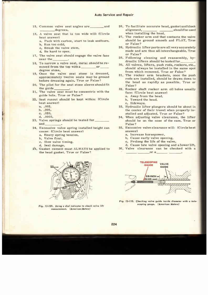
7/26/2019 Auto Service and Repair - Martin W. Stockel
http://slidepdf.com/reader/full/auto-service-and-repair-martin-w-stockel 224/224
26.
27.
2R
29.
30.
31.
19.
15.
Common valve seat angles
are-and
-degrees.
16.
A
valve seat
that is too
wide
wil l:
(Circle
best answer)
a.
Pack
with
carbon,
start
to leak andburn.
b.
Run too co1d.
c.
Break the valve
stem.
d.
Be hard
to
open.
1?.
The
valve
seat should engage the valve
face
near
the
18.
To narrow a valve
seat, metal
shouldbe re-
moved
from the top
witha or
degree
stone.
Once the valve
seat stone
is dressed,
Auto Service
ond
Repoir
To
facil itate
accurate head,
gasket
andblock
alignment,
_shouldbe
used
when
installíng
the head.
The
rocker arm
end
that
contacts the valve
should
be
ground
smooth and
FLAT.
True
or
False?
Hydraulic lifter parts are all very accurately
made
and are thus all
interchangeable. True
or
False?
Following
cleaning and reassembly, hy-
draulic l if ters
should b e tested for_.
All
valves, l if ters,
push
rods, rockers, etc.,
should always
be
installed
in the
same
spot
from
which removed. True
or
False
?
The
rocker
arm brackets,
once the
push