Embed Size (px)
Citation preview

FOR SAFETY MEASUREMENTS!!
WARNING
1. INTRODUCTION
2. SPECIFICATIONS
(23℃±5℃、<80%RH in non-condensing)1. DC VOLTAGE( V)
3-1. LCD
3-2. Function Switch
3-3. DH Key
3-5. Test Prods (Test Leads)
4-1. WARNINGS
4-2. GENERAL WARNINGS AND CAUTIONS
WARNING 1. Checks of Body and Test Leads
WARNING 3. Warning for High Voltage Measurements
WARNING 4. Dangerous Voltage Measurement Procedure
WARNING 2. Measurements of High Power Line (more than 6kVA) are Prohibited
3-4. / / Key
DIGITAL MULTIMETER
SK-6500
INSTRUCTION MANUAL
WARNING 7. Test Leads Disconnection
WARNING 5. Maximum Input Observance
WARNING 6. Correct Selection of FUNCTION Switch
3.NAME ILLUSTRATION
4.SAFETY PRECAUTIONS
, -, ~, mV, V, MΩ, kΩ, Ω, , , DH, BAT, AUTO and decimal point.
Σ
1 2 3 4
Range200.0mV 2.000V 20.00V 200.0V 600V
Resolution 100μV
1mV 10mV 100mV
1V
≧100MΩ
≒12MΩ
≒10MΩ
Accuracy±1.3%rdg±5dgt
±1.3%rdg±3dgt600V DC
Overload Protection:900V DC for 1 minute
Overload Protection:300V DC/AC rms for 1 minute
3. RESISTANCE(Ω)Range
200.0Ω 2.000kΩ 20.00kΩ 200.0kΩ2.000MΩ
20.00MΩ
Resolution 0.1Ω
1Ω 10Ω100Ω 1kΩ
10kΩ
≦1mA ≦0.3mA
≦40μA ≦4μA≦0.4μA
≦0.04μA
Accuracy
±2.0%rdg±4dgt ≦0.45V
2. AC VOLTAGE(~V)Range2.000V20.00V200.0V 600V
Resolution 1mV
10mV 100mV
1V
≒12MΩ
≒10MΩ
Accuracy
±2.0%rdg±8dgt
600V AC
4. DIODE TEST( )
Range
2.000V ≦1.7V
Test Current
≦0.7mA
Accuracy
±5.0%rdg±4dgt
Range
200.0Ω
Resolution
100mΩ ≒0.45V
Buzzer Sound Approx. 50Ω
or less 300V DC/ACrms for 1 minute
300V DC/ACrms for 1 minute
900V ACfor 1 minute
5. CONTINUITY TEST( )
±5.0%rdg±4dgt
1. LCD
5. Test ProdsTest Leads
2. FUNCTION Switch
3. DH Key
4. Ω/ / Key
AUTO
-
~
DHBAT
MΩ、kΩ、Ω
mV、V
AUTO DH BATMkΩ
~
Ω
Vm
Prior to use, to avoid an electrical shock hazard to the operator and/or damage to the instruments, read carefully the WARNINGS with the symbol listed in 「4. SAFETY PRECAUTIONS」,「5. MEASUREMENT PROCEDURES」and 「6. MAINTENANCE」of this instruction manual.
Important Symbols
The symbol listed in IEC 61010-1 and ISO 3864 means "Caution (refer to instruction manual)".
WARNING : The symbol in this manual advises the user of an electrical shock hazard that could result in serious injury or even death.
CAUTION : The symbol in this manual advises the user of an electrical shock hazard that could cause injury or material damages.
Do not measure High Power Line of more than 6kVA with this instrument. High Power Line is very dangerous and/or lethal to measure. High Power Line sometimes includes High Surge Voltage that could possibly induce dangerous arcs of explosive short in the instrument and could result in serious injury to the operator. Even if it is Low Power Line (Low Energy Circuit), when measuring high voltage, use extreme case to avoid electrical shock hazard and/or damage to the instrument.
Thank you for purchasing KAISE "SK-6500 DIGITAL MULTIMETER". To obtain the maximum performance of this instrument, read this Instruction Manual carefully, and take safe measurement.
Enables to hold display values by pressing DH key once and "DH" symbol appears on LCD. To cancel display hold, press DH key again and "DH" symbol disappears.
Connect red and black test prods to the circuit to be measured.Generally, Black Test Prod is connected to negative (ー) side, and Red Test Prod is connected to positive (+) side.
Enables to select resistance measurements, diode tests and continuity tests.
Before unpacking, examine the shipping cartons for any sign of damage. Unpack and inspect the instrument and accessories for any damage from mechanical shock, water leakage, or other causes. If any damage or missing item is found, consult the local dealer for replacement.
1-1. UNPACKING AND INSPECTION
2-1. GENERAL SPECIFICATIONS
2-2. MEASUREMENT SPECIFICATIONS
Make certain that following items are contained.
1. Digital Multimeter with Test Leads2. Note-book type Carrying Case3. Instruction Manual
Fig. 2
AllligatorClip
RedTest Prod
Fig. 3
Wall Outlet
WARNING 1. Do not let the children use the instrument or those people who are unable to recognize the dangers of electric measurements.WARNING 2. Do not make electric measurements in a naked or barefooted state. This will give electric shock hazard to the operator.
1. DISPLAY (LCD) a. Numerical Display : 3.5 digit LCD, Maximum reading 1999, 12mm high. b. Units and Symbols :
2. OPERATING PRINCIPLE : ⊿ conversion 3. RANGE SELECTION : Auto-Ranging 4. OVERLOAD INDICATION : "OL" symbol appears. 5. POLARITY : Auto-Polarity ("ー"symbol appears in minus) 6. BATTERY WARNING : "BAT" symbol appears when battery voltage becomes at approx. 2.4V or less.
7. SAMPLING RATE : 3 times / second 8. DISPLAY HOLD : Press DH key to hold display values. 9. CONTINUITY TEST : Buzzer sounds and symbol appears on a. Buzzer Sounds : at approx. 50Ωor less b. Open Circuit Voltage : approx. 0.45V10. OVERLOAD PROTECTION : a. V : 900V DC/AC maximum for 1 minute b. Ω/ / : 300V DC/AC rms maximum for 1 minute 11. DIELECTRIC STRENGTH : 3.52kV AC (50Hz) for 1 minute (between input terminal and case) 12. OPERATABLE TEMPERATURE & HUMIDITY : 0℃ to 40℃, 80%RH or lower in non-condensing. 13. STORAGE TEMPERATURE & HUMIDITY : -20℃ to 60℃, 70%RH or lower in non-condensing.14. TEMPERATURE COEFFICIENT : Accuracy in 23℃±5℃×0.1 / ℃15. POWER SUPPLY : 3V CR2032 Battery × 116. POWER CONSUMPTION : Approx. 2mA17. CONTINUOUS OPERATING TIME : 150 hours or more (in DC Voltage range, 0mV input)18. AUTO POWER OFF : Power turns off automaticaly after 15 minutes of any operation.19. SAFETY LEVEL : CE Marking approved (IEC-61010-1, CATⅡ600V, CATⅢ300V and EMC Test passed.)20. DIMEMSION & WEIGHT : 109(H)×55(W)×9(D)mm, Approx. 60g21. ACCESSORIES : 3V CR2032 Battery (installed)×1, Note-book type Carrying Case, Instruction Manual22. OPTIONAL ACCESSORY : 940 Alligator Clips
Set FUNCTION Switch to measurement position. OFF position V position V position Ω position position position
: Power turns off at this position: 0 to 600V DC measurements: 0 to 600V AC measurements: 0 to 20MΩ measurements: Diode tests: Continuity tests
Attach - (Black) and + (Red) Alligator Clips (optional) to Test Prods of Test Leads.Confirm that the power of the circuit to be measured is OFF. Then, connect Black Alligator Clip to - (earth) side and Red Alligator Clip to + (positive) side of the circuit to be measured.Place the instrument away from your body, and do not touch it with your hands. Also, take safety distance from the power source or the circuit to prevent any part of your body from touching dangerous voltage.Turn on power to the circuit to be measured and read the voltage on the Multimeter. Refer to the figure 1.
Turn off power to the circuit to be measured and discharge all capacitors in the circuit.Disconnect Alligator Clips of Test Prods from the circuit.
3.
4.
5.
6.
7.
8.
In case you want to measure live line, observe the following procedure.
Place the instrument away from your body.Set FUNCTION Switch to V or ~V position.Take safety distance for the power or the circuit to be measured to prevent any part of your body from touching dangerous voltage.Attach Black Alligator Clip to Black Test Prod. Then, connect Black Alligator Clip to - (earth) side of the circuit to be measured.Hold Red Test Prod with one hand and connect it to + (positive) side of the circuit to be measured.Read the voltage on LCD. Refer to the figure 2.
1.2.3.
4.
5.
6.
Disconnect Red Test Prod from the circuit and then disconnect Black Alligator Clip from the circuit.
7.
Do not attempt to measure voltage that might exceed 600V AC or DC, the specified maximum input of this instrument.
When taking measurement, always confirm that FUNCTION Switch is set to correct position. Do not measure voltage on Ω/ / position.
Prior to change FUNCTION Switch to another position when measuring, or opening Rear Case for replacement of battery, always dieconnect Test Leads from the circuit being measured.
Fig. 1
AlligatorClips
Test Prods
Correct knowledge about electric measurements is required because electric measurement is sometimes a very dangerous work.To eliminate possibility of injury to the operator and damage to the instrument, the following precautions and measurement procedures must be taken. Mis-use, abuse and carelessness cannot be prevented by any written word and is fully the operator's responsibility. Observing the following warnings and cautions, take safe measurements.
Before every measurement, do not fail to confirm that the body of this instrument and handle insulators of the attached Test Leads have no cracks nor any other damage on them. Make sure that the body and the handle insulators are free of dust, grease and moisture.
Do not measure with this instrument High Power Line (High Energy Circuits more than 6kVA) such as Distribution Transformers, Bus Bars, Power Line for Big Motors, etc. High Power Line is very dangerous as it sometimes includes High Surge Voltage that will induce short circuit in the instrument and results in shock hazard, Use the special instrument designed to measure High Power Line of more than 6kVA.
Even if to measure Low Energy Circuits (more than 100V) of electric/electronics appliances, heating elements, small motors, line cords and plugs, etc., High Voltage Measurements are very dangerous, Do not touch the Live Part of Multimeter, its Test Leads and the Circuit while it is on.Generally, shock hazard shall be exist at any part involving a potential in excess of 30V rms or 42.4V DC or peak and where a leakage current from that part to ground exceeds 0.5mA.
Always observe strictly the following measurement procedure when measuring dangerous voltage.
Before measurement, turn off power to the circuit to be measured.Set FUNCTION Switch to V or ~V position.
1.2.
LCD.
Max. InputVoltage
Max. InputVoltage
Open CircuitVoltage
Open CircuitVoltage
Overload Protection
Overload Protection
Overload Protection
Open CircuitVoltage
Input Resistance
Input Resistance
Test Current
Auto-RangingDirect Current (DC)Minus symbol (automatically appears when polarity is minus.)Alternating Current (AC)Diode TestContinuity TestDisplay HoldBattery WarningUnits of ResistanceUnits of Voltage
:::
:::::::
~
VV
SK-6500DIGITAL MULTIMETER
DH
OFF
CATⅡ 600V MAXCATⅢ 300V MAX
VV
SK-6500DIGITAL MULTIMETER
DH
OFF
CATⅡ 600V MAXCATⅢ 300V MAX
VV
SK-6500DIGITAL MULTIMETER
DH
OFF
CATⅡ 600V MAXCATⅢ 300V MAX
VV
SK-6500DIGITAL MULTIMETER
DH
OFF
CATⅡ 600V MAXCATⅢ 300V MAX
Caution (refer to instruction manual.)
~
70-1201-6500-2 0807
Alternating Current (AC)
Direct Current (DC)
Earth (Ground)
Double Insulation
9V 6F22 Battery
(Foward Connection)
Anode
Cathode
Anode
Cathode
(Reverse Connection)
5 6 7 8
-+
kΩ
3V CR2032 Bettery
PCB
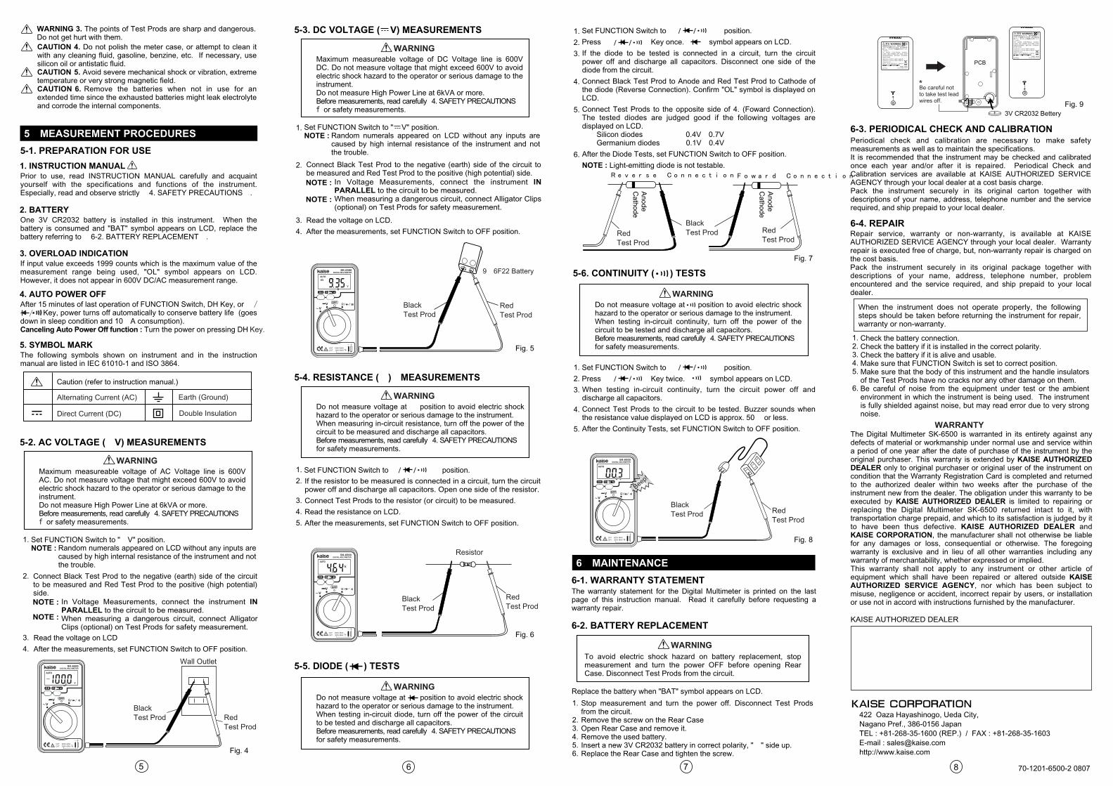
Maximum measureable voltage of AC Voltage line is 600V AC. Do not measure voltage that might exceed 600V to avoid electric shock hazard to the operator or serious damage to the instrument.Do not measure High Power Line at 6kVA or more.Before measurements, read carefully 「4. SAFETY PRECAUTIONS」for safety measurements.
Set FUNCTION Switch to "~V" position.NOTE : Random numerals appeared on LCD without any inputs are
caused by high internal resistance of the instrument and not the trouble.
NOTE : In Voltage Measurements, connect the instrument IN PARALLEL to the circuit to be measured.
NOTE : When measuring a dangerous circuit, connect Alligator Clips (optional) on Test Prods for safety measurement.
Connect Black Test Prod to the negative (earth) side of the circuit to be measured and Red Test Prod to the positive (high potential) side.
Read the voltage on LCD
After the measurements, set FUNCTION Switch to OFF position.
1.
2.
3.
4.
The Digital Multimeter SK-6500 is warranted in its entirety against any defects of material or workmanship under normal use and service within a period of one year after the date of purchase of the instrument by the original purchaser. This warranty is extended by KAISE AUTHORIZED DEALER only to original purchaser or original user of the instrument on condition that the Warranty Registration Card is completed and returned to the authorized dealer within two weeks after the purchase of the instrument new from the dealer. The obligation under this warranty to be executed by KAISE AUTHORIZED DEALER is limited to repairing or replacing the Digital Multimeter SK-6500 returned intact to it, with transportation charge prepaid, and which to its satisfaction is judged by it to have been thus defective. KAISE AUTHORIZED DEALER and KAISE CORPORATION, the manufacturer shall not otherwise be liable for any damages or loss, consequential or otherwise. The foregoing warranty is exclusive and in lieu of all other warranties including any warranty of merchantability, whether expressed or implied.This warranty shall not apply to any instrument or other article of equipment which shall have been repaired or altered outside KAISE AUTHORIZED SERVICE AGENCY, nor which has been subject to misuse, negligence or accident, incorrect repair by users, or installation or use not in accord with instructions furnished by the manufacturer.
When the instrument does not operate properly, the following steps should be taken before returning the instrument for repair, warranty or non-warranty.
Check the battery connection.Check the battery if it is installed in the correct polarity.Check the battery if it is alive and usable.Make sure that FUNCTION Switch is set to correct position.Make sure that the body of this instrument and the handle insulators of the Test Prods have no cracks nor any other damage on them.Be careful of noise from the equipment under test or the ambient environment in which the instrument is being used. The instrument is fully shielded against noise, but may read error due to very strong noise.
Periodical check and calibration are necessary to make safety measurements as well as to maintain the specifications.It is recommended that the instrument may be checked and calibrated once each year and/or after it is repaired. Periodical Check and Calibration services are available at KAISE AUTHORIZED SERVICE AGENCY through your local dealer at a cost basis charge.Pack the instrument securely in its original carton together with descriptions of your name, address, telephone number and the service required, and ship prepaid to your local dealer.
Repair service, warranty or non-warranty, is available at KAISE AUTHORIZED SERVICE AGENCY through your local dealer. Warranty repair is executed free of charge, but, non-warranty repair is charged on the cost basis.Pack the instrument securely in its original package together with descriptions of your name, address, telephone number, problem encountered and the service required, and ship prepaid to your local dealer.
KAISE AUTHORIZED DEALER
Prior to use, read INSTRUCTION MANUAL carefully and acquaint yourself with the specifications and functions of the instrument. Especially, read and observe strictly 「4. SAFETY PRECAUTIONS」.
One 3V CR2032 battery is installed in this instrument. When the battery is consumed and "BAT" symbol appears on LCD, replace the battery referring to 「6-2. BATTERY REPLACEMENT」.
CAUTION 4. Do not polish the meter case, or attempt to clean it with any cleaning fluid, gasoline, benzine, etc. If necessary, use silicon oil or antistatic fluid.CAUTION 5. Avoid severe mechanical shock or vibration, extreme temperature or very strong magnetic field.CAUTION 6. Remove the batteries when not in use for an extended time since the exhausted batteries might leak electrolyte and corrode the internal components.
WARNING 3. The points of Test Prods are sharp and dangerous. Do not get hurt with them.
5.MEASUREMENT PROCEDURES
6.MAINTENANCE
5-1. PREPARATION FOR USE
1. INSTRUCTION MANUAL
2. BATTERY
If input value exceeds 1999 counts which is the maximum value of the measurement range being used, "OL" symbol appears on LCD. However, it does not appear in 600V DC/AC measurement range.
The following symbols shown on instrument and in the instruction manual are listed in IEC 61010-1 and ISO 3864.
3. OVERLOAD INDICATION
After 15 minutes of last operation of FUNCTION Switch, DH Key, or Ω Key, power turns off automatically to conserve battery life (goes down in sleep condition and 10μA consumption).Canceling Auto Power Off function : Turn the power on pressing DH
4. AUTO POWER OFF
5. SYMBOL MARK
5-2. AC VOLTAGE (~V) MEASUREMENTS
5-3. DC VOLTAGE ( V) MEASUREMENTS
//
Key.
WARNING●
●●
Maximum measureable voltage of DC Voltage line is 600V DC. Do not measure voltage that might exceed 600V to avoid electric shock hazard to the operator or serious damage to the instrument.Do not measure High Power Line at 6kVA or more.Before measurements, read carefully 「4. SAFETY PRECAUTIONS」for safety measurements.
Set FUNCTION Switch to " V" position.NOTE : Random numerals appeared on LCD without any inputs are
caused by high internal resistance of the instrument and not the trouble.
NOTE : In Voltage Measurements, connect the instrument IN PARALLEL to the circuit to be measured.
NOTE : When measuring a dangerous circuit, connect Alligator Clips (optional) on Test Prods for safety measurement.
Connect Black Test Prod to the negative (earth) side of the circuit to be measured and Red Test Prod to the positive (high potential) side.
Read the voltage on LCD.
After the measurements, set FUNCTION Switch to OFF position.
1.
2.
3.
4.
WARNING●
●●
Fig. 4
Fig. 5
Fig. 6
Fig. 7
Fig. 8
Fig. 9
BlackTest Prod Red
Test Prod
BlackTest Prod
BlackTest Prod
RedTest Prod
BlackTest Prod
RedTest Prod
RedTest Prod
RedTest Prod
BlackTest Prod
Resistor
RedTest Prod
Wall Outlet
5-4. RESISTANCE (Ω) MEASUREMENTS
5-5. DIODE ( ) TESTS
6-1. WARRANTY STATEMENT
6-2. BATTERY REPLACEMENT
6-3. PERIODICAL CHECK AND CALIBRATION
6-4. REPAIR
Do not measure voltage at Ω position to avoid electric shock hazard to the operator or serious damage to the instrument.When measuring in-circuit resistance, turn off the power of the circuit to be measured and discharge all capacitors.Before measurements, read carefully 「4. SAFETY PRECAUTIONS」for safety measurements.
Set FUNCTION Switch to position. 1.
2.
3.
4.
5.
WARNING●
●
●
Do not measure voltage at position to avoid electric shock hazard to the operator or serious damage to the instrument.When testing in-circuit diode, turn off the power of the circuit to be tested and discharge all capacitors.Before measurements, read carefully 「4. SAFETY PRECAUTIONS」for safety measurements.
WARNING
WARNING
WARRANTY
●
●
●
Ω/ /
5-6. CONTINUITY ( ) TESTS
Do not measure voltage at position to avoid electric shock hazard to the operator or serious damage to the instrument.When testing in-circuit continuity, turn off the power of the circuit to be tested and discharge all capacitors.Before measurements, read carefully 「4. SAFETY PRECAUTIONS」for safety measurements.
WARNING●
●
●
If the resistor to be measured is connected in a circuit, turn the circuit power off and discharge all capacitors. Open one side of the resistor.
Connect Test Prods to the resistor (or circuit) to be measured.
Read the resistance on LCD.
After the measurements, set FUNCTION Switch to OFF position.
Set FUNCTION Switch to position.
Press Key once. symbol appears on LCD. 1.
2.
3.
4.
5.
6.
Ω/ /
If the diode to be tested is connected in a circuit, turn the circuit power off and discharge all capacitors. Disconnect one side of the diode from the circuit.
Connect Black Test Prod to Anode and Red Test Prod to Cathode of the diode (Reverse Connection). Confirm "OL" symbol is displayed on LCD.
Connect Test Prods to the opposite side of 4. (Foward Connection). The tested diodes are judged good if the following voltages are displayed on LCD. Silicon diodes・・・・・・・ 0.4V~0.7V Germanium diodes・・・・ 0.1V~0.4V
After the Diode Tests, set FUNCTION Switch to OFF position.
NOTE : Light-emitting diode is not testable.
“ ”
Ω/ / “ ”
Set FUNCTION Switch to position.
Press Key twice. symbol appears on LCD.
1.
2.
3.
4.
5.
1. 2. 3. 4. 5. 6.
1. 2. 3. 4. 5. 6.
Ω/ /
When testing in-circuit continuity, turn the circuit power off and discharge all capacitors.
Connect Test Prods to the circuit to be tested. Buzzer sounds when the resistance value displayed on LCD is approx. 50Ω or less.
After the Continuity Tests, set FUNCTION Switch to OFF position.
“ ”
“ ”Ω/ / “ ”
“ ”
The warranty statement for the Digital Multimeter is printed on the last page of this instruction manual. Read it carefully before requesting a warranty repair.
Replace the battery when "BAT" symbol appears on LCD.
To avoid electric shock hazard on battery replacement, stop measurement and turn the power OFF before opening Rear Case. Disconnect Test Prods from the circuit.
Stop measurement and turn the power off. Disconnect Test Prods from the circuit.Remove the screw on the Rear CaseOpen Rear Case and remove it.Remove the used battery.Insert a new 3V CR2032 battery in correct polarity, "+" side up.Replace the Rear Case and tighten the screw.
422 Oaza Hayashinogo, Ueda City, Nagano Pref., 386-0156 JapanTEL : +81-268-35-1600 (REP.) / FAX : +81-268-35-1603E-mail : [email protected]://www.kaise.com
+ 3V CR2032
VV
SK-6500DIGITAL MULTIMETER
DH
OFF
CATⅡ 600V MAXCATⅢ 300V MAX
VV
SK-6500DIGITAL MULTIMETER
DH
OFF
CATⅡ 600V MAXCATⅢ 300V MAX
VV
SK-6500DIGITAL MULTIMETER
DH
OFF
CATⅡ 600V MAXCATⅢ 300V MAX
VV
SK-6500DIGITAL MULTIMETER
DH
OFF
CATⅡ 600V MAXCATⅢ 300V MAX
Ω
*Be careful notto take test lead wires off.
Beep!