Embed Size (px)
Citation preview

source: https://doi.org/10.7892/boris.94875 | downloaded: 16.3.2022
Author’s Accepted Manuscript
The swiss approach for a heartbeat-driven lead- andbatteryless pacemaker
Adrian Zurbuchen, Andreas Haeberlin, LukasBereuter, Joerg Wagner, Alois Pfenniger, SammyOmari, Jakob Schaerer, Frank Jutzi, ChristophHuber, Juerg Fuhrer, Rolf Vogel
PII: S1547-5271(16)30917-1DOI: http://dx.doi.org/10.1016/j.hrthm.2016.10.016Reference: HRTHM6896
To appear in: Heart Rhythm
Cite this article as: Adrian Zurbuchen, Andreas Haeberlin, Lukas Bereuter, JoergWagner, Alois Pfenniger, Sammy Omari, Jakob Schaerer, Frank Jutzi, ChristophHuber, Juerg Fuhrer and Rolf Vogel, The swiss approach for a heartbeat-drivenlead- and batteryless pacemaker, Heart Rhythm,http://dx.doi.org/10.1016/j.hrthm.2016.10.016
This is a PDF file of an unedited manuscript that has been accepted forpublication. As a service to our customers we are providing this early version ofthe manuscript. The manuscript will undergo copyediting, typesetting, andreview of the resulting galley proof before it is published in its final citable form.Please note that during the production process errors may be discovered whichcould affect the content, and all legal disclaimers that apply to the journal pertain.
www.elsevier.com/locate/buildenv
The Swiss approach for a heartbeat-
driven lead- and batteryless pacemaker
Short title: Heartbeat-driven lead- and batteryless pacemaker
Dr. Adrian Zurbuchen1,2,3
, Dr. Dr. Andreas Haeberlin1,2,4
, MSc. Lukas Bereuter1,2
, MSc. Joerg
Wagner1, Dr. Alois Pfenniger
1, MSc. Sammy Omari
1,2, BSc. Jakob Schaerer
1,2, Frank Jutzi
5,
Dr. Christoph Huber6,7
, Dr. Juerg Fuhrer2, Prof. Dr. Dr. Rolf Vogel
1,8
1 ARTORG Cardiovascular Engineering, University of Bern, Bern, Switzerland
2 Department of Cardiology, Bern University Hospital and University of Bern, Bern, Switzerland
3 Department of Electrical Engineering and Computer Science, University of Michigan, Ann Arbor, MI, USA
4 Department of Clinical Research, University of Bern, Bern, Switzerland
5 Atelier für Uhren, Frank Jutzi, Wichtrach, Switzerland
6 Department of Cardiovascular Surgery, Geneva University Hospital, Geneva, Switzerland
7 Department of Cardiovascular Surgery, Bern University Hospital and University of Bern, Bern, Switzerland
8 Department of Cardiology, Bürgerspital Solothurn, Solothurn, Switzerland
Address for correspondence:
Adrian Zurbuchen
University of Michigan
Electrical Engineering and Computer Science
1301 Beal Avenue
Ann Arbor, Michigan, 48109-2122, USA
Tel.: +1 (734) 730-0898
Fax.: +1 (734) 763-9324
E-mail: [email protected]
Author’s Conflict of Interest: none
KEYWORDS: pacing, leadless, batteryless, energy harvesting, clockwork

Introduction
Active medical implants play a crucial role in cardiovascular medicine. Their task is to monitor and
treat patients with minimal side effects. Furthermore, they are expected to operate autonomously over
a long period of time. However, the most common electrical implants, cardiac pacemakers - as all
other electrical implants - run on an internal battery which needs to be replaced prior to its end of life.
Typical pacemaker battery lifecycles are in the range of eight to ten years 1 however strongly depend
on the device type and usage. Therefore, many patients are confronted with repeated surgical
interventions 2 which increase the risk of complications such as infections or bleedings
3–5 and are
costly. Furthermore, the battery accounts for a majority of a pacemaker’s volume and weight. Its large
footprint demands locating conventional pacemakers at a remote pectoral implantation site. Moreover,
the large battery is responsible for another major limitation: to deliver the electrical stimulus at the
pacing site, conventional pacemakers require long leads. They are exposed to continuous mechanical
stress and are prone to fracture. Especially for younger patients this is a critical factor 6,7
.
In brief, batteries are the Achilles heel in the design of cardiac pacemakers. Therefore, an
inexhaustible power supply and a leadless design are highly desirable. Different approaches have been
investigated to extract energy from various sites and sources of the body 8,9
as for example the knee 10
,
the chemical reaction of glucose and oxygen in dedicated fuel cells 11
, the skin-penetrating sunlight by
solar cells 12
, the body movements using nanowires 13
or the body heat 14
.
The human heart is another convenient energy source for medical implants, in particular for cardiac
pacemakers: Regardless of a person’s activity, the myocardium contracts in a repetitive manner and
thereby reaches high accelerations of ≈ 2 m/s2 15
, an excellent endurance (> 2.5 billion cycles in a 70
year lifetime) and a large hydraulic power (≈ 1.4 W with mean aortic pressure pmean ≈ 100 mmHg and
cardiac output CO ≈ 6.3 l/min 16
). Researchers have been exploring ways to take advantage of this
energy source, for instance by harvesting energy from blood pressure differences using a micro barrel
17 or a dual-chamber system
18. Furthermore, piezoelectric materials
19–22 as well as electromagnetic
systems 23,24
have been utilized to harvest energy from the ventricular wall motion.

2
The automatic clockwork of a wrist watch is an example of a well-established and successful approach
to convert human motion into electrical energy. The automatic clockwork captures the motion of a
person’s wrist during daily activities by an oscillation weight. A mechanical transmission gear and an
electromagnetic generator finally convert the oscillations into electrical energy, which powers the
wrist watch. Such energy harvesting mechanisms typically generate a power of 5 – 10 μW on average
but can get as high as 1 mW depending on the person’s activity 25–27
. As a comparison, contemporary
leadless pacemakers require less than 10 µW mean power to operate (according to device
manufacturers’ reference manuals).
The aim of this study is to demonstrate the feasibility of battery- and leadless cardiac pacing using a
custom-made pacemaker supplied by an energy harvesting mechanism derived from a reliable Swiss
wrist watch. The device’s ability to harvest energy from heart motions was tested during experiments
with a robot that mimics human heart motions. Finally, the pacemaker prototype was tested during an
acute animal trial to show the feasibility of pacing a heart with its own energy.
Methods
Myocardial contractions provide continuous energy in the form of mechanical motion. An energy
harvesting mechanism was introduced to convert the heart’s mechanical energy into electrical energy.
A dedicated electronics was developed to process and store the converted energy and to treat the heart
with minute pacing stimuli (cf. Figure 1). As the results will show, during this process, only a small
portion (~ 80 μW) of the heart’s total energy (~ 1.4 W) is converted and can be used to power the
devices electronics. The following subsections describe the energy harvesting mechanism and the
pacemaker electronics, as well as the setup for testing the device on the bench and in-vivo.
Energy Harvesting Mechanism
The energy harvesting mechanism is based on an automatic clockwork (ETA 204, ETA SA, Grenchen,
Switzerland). The system was adapted to harvest energy from heart motion: time and date indicating
parts were removed and a new oscillation weight was developed 28
. The total weight of 9.2 g was
3
achieved by skeletonizing the clockwork’s framework. This reduced the energy harvesting system to
four main components (cf. Figure 2) with the following functions:
1. The oscillation weight translates externally applied accelerations into an oscillating rotational
motion. To increase its sensitivity to heart motions the oscillation weight was optimized and
redesigned using a mathematical model reported previously 24,28
. The new oscillation weight
features a mass of 7.7 g and is made of a platinum alloy (950 PT CO).
2. The mechanical rectifier translates the previously described oscillation into a unidirectional
rotation. This allows harvesting energy from rotations in both directions.
3. The unidirectional rotation spans a spiral spring that temporarily stores the energy in
mechanical form.
4. At last, an electrical micro generator (MG205, Kinetron B.V., Netherlands) converts a
rotational motion into an electrical signal. When the torque of the spiral spring equals the
holding torque of the generator, the spring unwinds and drives the electrical micro generator.
The resulting impulse comprises about 80 µJ at a load resistance of 1 kΩ.
Pacemaker Electronics
The electronics of pacemakers typically include different features such as sensing, pacing or automatic
rate adaptation. Each individual feature consumes energy from the battery and determines the lifetime
of the device. Therefore, in the development of modern pacemaker electronics, it is important to
reduce the power consumption of the electronics to a minimum. But their lifetime is also determined
by external factors: a small tissue impedance, a high pacing threshold voltage, a wide pacing pulse or a
high pacing frequency will increase the overall power consumption of a pacemaker electronics.
The here presented pacemaker electronics inherits two main functions that serve the purpose of
demonstrating the feasibility of battery- and leadless pacing (cf. Figure 3):
1. An energy management circuit (EMC) receives an alternating current impulse from the micro
generator that needs to be rectified. Each such impulse is temporarily stored in a buffer
capacity (47 µF capacitor TM8T476K010UBA, Vishay, United States). The voltage level in
4
the buffer capacity can reach levels between 0.8 V and 6 V, which mainly depends on the
actual energy conversion rate of the energy harvesting mechanism for the present myocardial
motion.
2. A simple pacemaker circuit (PMC) employs the buffered energy to generate pacing stimuli.
Solely relying on the previously harvested energy, the stimulus’ voltage amplitude adopts the
present voltage level of the buffer capacity (ranging from 0.8 V to 6 V). The pacemaker
performs V00-pacing at a fixed rate and impulse duration of 120 bpm and 0.5 ms,
respectively. In addition to its pacing abilities, the PMC features a mechanism to inhibit
pacing during the implantation procedure.
Assuming the energy harvesting mechanism converts enough energy to provide a constant supply
voltage of 3 V, the internal power consumption of the electronics can be measured at 4.2 µW when
pacing is inhibited. This internal power consumption is defined by the circuit design, whereas the
power for generating a typical pacemaker stimulus (3 V / 0.5 ms @ 120 bpm) depends on the
myocardial tissue impedance and can alter over time. Assuming a constant tissue impedance of 500 Ω
the pacing stimulus requires an additional 18 µW mean power. Therefore, the energy harvesting
mechanism needs to generate 22.2 µW mean power to cover the pacemaker electronics’ total power
consumption.
Overall Pacemaker Design
The energy harvesting mechanism and the pacemaker electronics are combined in a custom-made
housing (cf. Figure 4), manufactured by 3D printing (Alaris30, Objet Ltd., Israel) from polymer
(VeroWhite FullCure830, Objet Ltd.). The housing provides six eyelets to suture the pacemaker onto
the epicardium of the ventricle. Two pacemaker electrodes are located on the bottom side of the
housing and pierce into the myocardium. The stainless steel electrodes measure 0.5 mm in diameter
and 3 mm in length. The same pins are accessible from the top of the housing to perform in-vivo
measurements of the R-wave amplitude, the pacing threshold and the electrode impedance by
connecting a conventional pacemaker programmer (CareLink®, Medtronic, United States).
Furthermore, two different metal pins protrude from the lid of the housing, which inhibit pacing when

5
shortcut. For permanent inhibition during the attachment of the pacemaker we used a small permanent
ring magnet to shortcut the protruding ends of the pins. By removing the magnet, the pacemaker starts
V00-pacing at the predefined frequency of 120 bpm. Finally, a transparent polycarbonate lid seals the
housing and allows monitoring the deflection of the oscillation weight. The device weights 12 g,
whereas the oscillation weight accounts for 64 % of the total device mass. The housing has an outer
diameter and thickness of 27 mm and 8.3 mm, respectively.
Bench Experiment
Prior to the in-vivo experiment, the energy harvesting mechanism was tested on a robot dedicated to
mimic human heart motions. The device is mounted on the robot’s endeffector platform which is
linked by lever arms to six actuating motors. The robot was programmed to mimic heart motion
profiles of previously acquired three-dimensional MRI tagging data 24
. The data represents the
myocardial motion of the left ventricle over a period of one heart cycle (HR = 85 bpm) of a healthy
volunteer in supine position.
During this bench experiment, six different points on the left ventricular myocardium (anterior, left
lateral and posterior wall for the apical and basal section) were selected. Sequentially, the robot
exposed the device to these motion profiles. The generated mean power for each motion profile was
measured over a period of 60 seconds and repeated five times.
In-Vivo Study
The in-vivo experiment was performed on a 60 kg domestic pig. The pig was under inhalation
anaesthesia and placed in recumbent position. The trial was approved by the Swiss Federal Veterinary
Office and performed in compliance with the Guide for the Care and Use of Laboratory Animals 29
.
Thoracotomy and pericardiotomy allowed suturing the pacemaker directly on the epicardium of the
left ventricle in an antero-apical position (cf. Figure 5).
6
Results
Bench Experiment
The results of the bench experiments illustrate high mean output power values, especially for locations
on the left side of the human heart (cf. Figure 6). For all six epicardial locations the harvesting
mechanism generated sufficient electrical power to meet the demands of modern cardiac pacemakers
( < 10 µW 30
). Especially left lateral locations, where the device generated a constant mean output
power of 82.0 ± 4.4 µW (apical) and 90.1 ± 0.7 µW (basal), seem to be favorable for the harvesting
mechanism. These sites are also most easily accessible by a small lateral thoracotomy. But also at the
anterior and posterior-basal locations, the device exceeded the required mean power by a factor of 3
and 5, respectively.
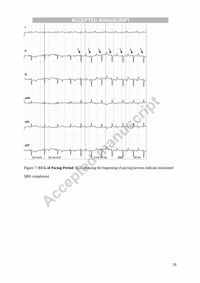
In-Vivo Study
The lead- and batteryless pacemaker was sutured to the antero-apical position of the pig’s heart for 30
minutes. The electrode’s pacing threshold voltage was measured at 0.9 V / 0.5 ms across a tissue
impedance of 1025 Ω at 5 V. The heart movements accelerated the device and resulted in oscillation
weight amplitudes of about 90 degrees (cf. supplementary movie). This allowed the harvesting
mechanism to extract enough energy to power the internal pacemaker electronics. After removing the
inhibitor magnet, the device performed continuous epicardial V00-pacing at 120 bpm (cf. Figure 7,
stimulated beats are indicated).
Discussion
We demonstrated that it is feasible to use the heart’s kinetic energy to perform cardiac pacing by
means of a reliable energy-converting clockwork mechanism. Our approach of gathering energy
directly from the heart allowed us to introduce a leadless and batteryless pacemaker.
During bench and in-vivo tests, the device was exposed to physiological cardiac contractions (i. e.
normal left ventricular function). It is expected that heart failure has a negative impact on the energy
extraction rate of the device. However, the bench experiment illustrated a surplus of energy that might
compensate the loss in myocardial contraction.
7
The implantation of the device on the left ventricle requires a mini thoracotomy which can be achieved
by a standard surgical intervention. Alternatively, a catheter-based transvenous implantation could be
envisioned for an endocardial fixation at the right ventricular septum. This would require to change the
device from a disc- into a rod-shaped design.
The energy supply of the generator is an intermittent signal and not necessarily synchronous with the
energy demand of the pacemaker electronics. Therefore, a 47 µF capacitor has been introduced to
buffer the generated energy. In case of an energy shortage, this capacity is sufficient to power the
pacemaker over a period of 20 to 60 seconds. As a safety precaution for a future medical implant, this
storage capacity would need to be increased.
Swiss automatic wristwatches are renowned for their very long lifetime and they have the reputation
of being precise and extremely reliable. In daily use, wristwatches are often subject to tough
conditions such as high mechanical stress, sunlight that can alter materials (e.g. lubricant or polymeric
components) or the exposure to large temperature variations. In addition, aesthetic design criteria
further increase the complexity and requirements of today’s wristwatches. However, the requirements
for an energy harvesting mechanism in future battery- and leadless pacemakers are rather different.
Encapsulated in the human body, the device is well protected against sunlight, external mechanical
stress and temperature variations. Moreover, without the need to indicate time, the clockwork
construction can be simplified to further improve the resistance to wear.
The prototype housing has a very functional design for testing the concept during an acute in-vivo
study exclusively. It protects the clockwork and the electrical components against liquids and
mechanical effects. Furthermore, it provides a transparent lid and interfaces to the electrical circuit for
measuring and controlling reasons. In addition to that, a housing would have to feature hermetic
sealing, biocompatible materials and surface treatment to ensure biocompatibility and device
functioning for long-term studies.
The current device is designed as a conceptual prototype whereas miniaturization was a secondary
objective. The current overall device size (diameter = 27 mm, height = 8.3 mm) and weight could be
drastically reduced by changing manufacturing processes (e.g. by introducing application-specific
8
integrated circuits (ASICs)), by using other materials (e.g. exchange rapid prototyping plastic housing
by a thin-walled metal housing) or by redesigning components (e.g. housing design that incorporates
the clockwork’s transmission gear and generator).
The electronics of our pacemaker prototype was built with discrete analogue components. This
technique is advantageous for prototyping due to its ease of handling and cost effectiveness. However,
it is very limited for designing small low-power applications. By using ASICs, as it is used in
commercially available pacemakers and shown by Wong et al. 31
, the overall device size and its power
consumption can be further reduced significantly.
Acknowledgements
We thank Stijn Vandenberghe for his support and valuable advice. Our gratitude extends to the entire
team of the Experimental Surgery Institute of the Department of Clinical Research, University of
Bern, for their support in animal studies. Furthermore, we thank Otto Aeby and Danael Gasser for
their assistance in mechanical manufacturing.
Funding Sources
This work was supported by the Swiss Heart Foundation; the Commission for Technology and
Innovation (KTI-CTI 12589.1 PFLS-LS); the Research Funds of the Department of Cardiology,
Bürgerspital Solothurn, Switzerland and the Department of Cardiology at the Bern University
Hospital, Switzerland.
9
References
1. Aizawa Y, Kunitomi A, Nakajima K, Kashimura S, Katsumata Y, Nishiyama T, Kimura T,
Nishiyama N, Tanimoto Y, Kohsaka S, Takatsuki S, Fukuda K: Risk factors for early
replacement of cardiovascular implantable electronic devices. Int J Cardiol 2015; 178:99–101.
2. Mond HG, Proclemer A: The 11th World Survey of Cardiac Pacing and Implantable
Cardioverter-Defibrillators: Calendar Year 2009–A World Society of Arrhythmia’s Project.
Pacing Clin Electrophysiol 2011; 34:1013–1027.
3. Kirkfeldt RE, Johansen JB, Nohr EA, Jørgensen OD, Nielsen JC: Complications after cardiac
implantable electronic device implantations: an analysis of a complete, nationwide cohort in
Denmark. Eur Heart J 2014; 35:1186–1194.
4. Polyzos KA, Konstantelias AA, Falagas ME: Risk factors for cardiac implantable electronic
device infection: a systematic review and meta-analysis. EP Eur 2015; 17:767–777.
5. Udo EO, Zuithoff NPA, van Hemel NM, de Cock CC, Hendriks T, Doevendans PA, Moons
KGM: Incidence and predictors of short- and long-term complications in pacemaker therapy:
The FOLLOWPACE study. Heart Rhythm 2012; 9:728–735.
6. Fortescue EB, Berul CI, Cecchin F, Walsh EP, Triedman JK, Alexander ME: Patient, procedural,
and hardware factors associated with pacemaker lead failures in pediatrics and congenital heart
disease. Heart Rhythm 2004; 1:150–159.
7. Odim J, Suckow B, Saedi B, Laks H, Shannon K: Equivalent performance of epicardial versus
endocardial permanent pacing in children: a single institution and manufacturer experience. Ann
Thorac Surg 2008; 85:1412–1416.
8. Starner T: Human-powered wearable computing. IBM Syst J 1996; 35:618–629.
9. Romero E, Warrington RO, Neuman MR: Energy scavenging sources for biomedical sensors.
Physiol Meas 2009; 30:R35-62.

10
10. Platt SR, Farritor S, Garvin K, Haider H: The use of piezoelectric ceramics for electric power
generation within orthopedic implants. IEEEASME Trans Mechatron 2005; 10:455–461.
11. Kerzenmacher S, Ducrée J, Zengerle R, von Stetten F: Energy harvesting by implantable
abiotically catalyzed glucose fuel cells. J Power Sources 2008; 182:1–17.
12. Haeberlin A, Zurbuchen A, Schaerer J, Wagner J, Walpen S, Huber C, Haeberlin H, Fuhrer J,
Vogel R: Successful pacing using a batteryless sunlight-powered pacemaker. Europace 2014;
16:1534–1539.
13. Qin Y, Wang X, Wang ZL: Microfibre-nanowire hybrid structure for energy scavenging. Nature
2008; 451:809–813.
14. Wang Z, Leonov V, Fiorini P, Van Hoof C: Realization of a wearable miniaturized
thermoelectric generator for human body applications. Sens Actuators Phys 2009; 156:95–102.
15. Staehle F, Jung BA, Bauer S, Leupold J, Bock J, Lorenz R, Föll D, Markl M: Three-directional
acceleration phase mapping of myocardial function. Magn Reson Med 2011; 65:1335–1345.
16. Pfenniger A, Jonsson M, Zurbuchen A, Koch VM, Vogel R: Energy harvesting from the
cardiovascular system, or how to get a little help from yourself. Ann. Biomed. Eng. 2013, pp.
2248–2263.
17. Deterre M, Lefeuvre E, Zhu Y, Woytasik M, Boutaud B, Dal Molin R: Micro Blood Pressure
Energy Harvester for Intracardiac Pacemaker. J Microelectromechanical Syst 2014; 23:651–660.
18. Roberts P, Stanley G, Morgan JM: Abstract 2165: Harvesting the Energy of Cardiac Motion to
Power a Pacemaker. Circulation 2008; 118:S_679.
19. Karami MA, Inman DJ: Powering pacemakers from heartbeat vibrations using linear and
nonlinear energy harvesters. Appl Phys Lett 2012; 100:42901-042901–042904.

11
20. Dagdeviren C, Yang BD, Su Y, et al.: Conformal piezoelectric energy harvesting and storage
from motions of the heart, lung, and diaphragm. Proc Natl Acad Sci U S A 2014; 111:1927–
1932.
21. Li H, Tian C, Deng ZD: Energy harvesting from low frequency applications using piezoelectric
materials. Appl Phys Rev 2014; 1:41301.
22. Alrashdan MHS, Hamzah AA, Majlis B: Design and optimization of cantilever based
piezoelectric micro power generator for cardiac pacemaker. Microsyst Technol 2014; 21:1607–
1617.
23. Goto H, Sugiura T, Harada Y, Kazui T: Feasibility of using the automatic generating system for
quartz watches as a leadless pacemaker power source. Med Biol Eng Comput 1999; 37:377–380.
24. Zurbuchen A, Pfenniger A, Stahel A, Stoeck CT, Vandenberghe S, Koch VM, Vogel R: Energy
harvesting from the beating heart by a mass imbalance oscillation generator. Ann Biomed Eng
2013; 41:131–141.
25. Sasaki K, Osaki Y, Okazaki J, Hosaka H, Itao K: Vibration-based automatic power-generation
system. Microsyst Technol 2005; 11:965–969.
26. Paradiso JA, Starner T: Energy Scavenging for Mobile and Wireless Electronics. IEEE Pervasive
Comput 2005; 4:18–27.
27. Xie L, Menet CG, Ching H, Du R: The Automatic Winding Device of a Mechanical Watch
Movement and Its Application in Energy Harvesting. J Mech Des 2009; 131:071005–071005.
28. Zurbuchen A, Haeberlin A, Pfenniger A, Bereuter L, Schaerer J, Jutzi F, Huber C, Fuhrer J,
Vogel R: Towards Batteryless Cardiac Implantable Electronic Devices - The Swiss Way. IEEE
Trans Biomed Circuits Syst 2016; PP:1–9.
12
29. National Research Council (US) Committee for the Update of the Guide for the Care and Use of
Laboratory Animals: Guide for the Care and Use of Laboratory Animals. 8th Edition.
Washington (DC): National Academies Press (US), 2011,.
30. Wong LSY, Hossain S, Ta A, Edvinsson J, Rivas DH, Naas H: A very low-power CMOS mixed-
signal IC for implantable pacemaker applications. IEEE J Solid-State Circuits 2004; 39:2446–
2456.
31. Wong LSY, Hossain S, Ta A, Edvinsson J, Rivas DH, Naas H: A very low-power CMOS mixed-
signal IC for implantable pacemaker applications. IEEE J Solid-State Circuits 2004; 39:2446–
2456.

13
Figures
Figure 1: Working principle: The mechanical heart motion is converted into electrical impulses by an
energy harvesting mechanism. The pacemaker electronics processes the electrical impulses,
temporarily stores the energy and generates electrical stimuli to pace the myocardium with two
pacemaker electrodes.
Figure 2: Energy Harvesting Mechanism: The schematics of the energy harvesting mechanism
illustrating a) an oscillation weight, b) a mechanical rectifier, c) a spiral spring and d) an
electromagnetic micro generator.

14
Figure 3: Pacemaker Schematics: The schematics of the pacemaker electronics illustrating a) the
clockwork’s micro generator, b) a bridge rectifier, c) a buffer capacity, d) a pacemaker stimulus
generator and e) a switch to apply the stimulus to the heart with f) the option of inhibit pacing by
shortcutting the two poles and g) a pacemaker stimulus as output.
15
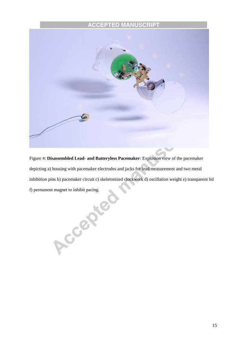
Figure 4: Disassembled Lead- and Batteryless Pacemaker: Explosion view of the pacemaker
depicting a) housing with pacemaker electrodes and jacks for lead measurement and two metal
inhibition pins b) pacemaker circuit c) skeletonized clockwork d) oscillation weight e) transparent lid
f) permanent magnet to inhibit pacing.

16
Figure 5: In-Vivo Pacing: Pacemaker sutured on the heart and inhibited by the magnet (cf.
supplementary movie).

17
Figure 6: Bench Experiment: The power generated by the energy harvesting mechanism when
exposed to six different heart acceleration profiles. The five asterisks at each location indicate the
generated mean output power of the individual measurements whereas the bar plots represent their
overall median value.
18
Figure 7: ECG of Pacing Period: ECG showing the beginning of pacing (arrows indicate stimulated
QRS complexes)