Embed Size (px)
Citation preview

AUSTRALITEfire, acoustics & thermal technical manual
AUGUST 2017

CONTENTS
Fire Resistance Levels / 3
How to Use Structural Adequacy Charts / 5
Non-Loadbearing Structural Adequacy FRL’s / 6
Loadbearing Structural Adequacy FRL’s / 12
Partially Reinforced Masonry / 17
Accousitc Ratings / 18
Thermal Mass / 26
Properties of Concrete Masonry / 26
R-values for Concrete Masonry and Linings / 27
AUSTRALITE
/ 2 /

/ 3 /
TECHNICAL MANUAL
FIRE RESISTANCElevels
In 2008 - 2009, a series of fire tests were done on what is now known as AustraLite masonry. When calculated to the requirements of
AS3700:2011, Section 6, they were proven to achieve much higher Fire Resistance Levels (FRLs) than standard concrete masonry units:
The maximum Srfs for AustraLite are:
60 minutes: 22.93 Loadbearing 27.83 NON-Loadbearing
90 minutes: 21.31 Loadbearing 27.83 NON-Loadbearing
120 minutes: 20.16 Loadbearing 26.32 NON-Loadbearing
180 minutes: 18.54 Loadbearing 23.30 NON-Loadbearing
240 minutes: 17.39 Loadbearing 21.16 NON-Loadbearing
The graphs on pages 4 to 14 show the AS3700 formulae for each of these conditions.
Integrity FRL: The NON-Loadbearing test (EWFA 2345.600) of a 90mm wall with Srf = 25.83 achieved a 240- minute Integrity FRL.
According to AS3700, Clause 6.4.3, NON-Loadbearing AustraLite masonry with t ≥ 90mm and Srf ≤ 25.83 will
achieve a 240-minute Integrity FRL.
Diagram
Structural Adequacy FRL:
The Slenderness ratio (Srf) of a proposed wall is calculated by the formulae in AS3700,
Clause 6.3.2.2 factoring the wall’s spanning height/length, thickness and which edges are restrained.
1.0
2.0
3.0
4.0
5.0
6.0
7.0
8.0
9.0
Hei
ght o
f wal
l bet
wee
n su
ppor
ts (m
)
1.0 2.0 3.0 4.0 5.0 6.0 7.0 8.0 9.0
Length of wall between supports (m)
NON-LOADBEARINGLaterally supported along top, both ends and base.
SUPPORT
SUPPORT
190 mm
140 mm
110 mm
SUPPORTSUPPORT
Srf=25.83
90 mm
1.0
2.0
3.0
4.0
5.0
6.0
7.0
8.0
9.0
Hei
ght o
f wal
l bet
wee
n su
ppor
ts (m
)
1.0 2.0 3.0 4.0 5.0 6.0 7.0 8.0 9.0
Length of wall between supports (m)
NON-LOADBEARINGLaterally supported along top, one end and base.
SUPPORT
SUPPORT
190 mm140 mm110 mm
SUPPORT
Srf=25.83
90 mm

AUSTRALITE
/ 4 /
1.0
2.0
3.0
4.0
5.0
6.0
7.0
8.0
9.0
Hei
ght o
f wal
l bet
wee
n su
ppor
ts (m
)
1.0 2.0 3.0 4.0 5.0 6.0 7.0 8.0 9.0
Length of wall between supports (m)
LOADBEARINGLoadLaterally supported along top, both ends and base.
SUPPORT
SUPPORT
190 mm
140 mm
110 mm
SUPPORT
SUPPORT
Srf=21.14
1.0
2.0
3.0
4.0
5.0
6.0
7.0
8.0
9.0
Hei
ght o
f wal
l bet
wee
n su
ppor
ts (m
)
1.0 2.0 3.0 4.0 5.0 6.0 7.0 8.0 9.0
Length of wall between supports (m)
LOADBEARINGLaterally supported along top, one end and base.
SUPPORT
SUPPORT
190 mm140 mm110 mm
SUPPORT
Srf=21.14
FIRE RESISTANCE LEVELS
The Loadbearing test (EWFA 2345.400) of 110mm AustraLite with Srf = 21.14 achieved a 240- minute Integrity FRL
Loadbearing AustraLite walls with t ≥ 110mm & Srf ≤ 21.14 achieve a 240-minute Integrity FRL.
Loadbearing 90mm AustraLite is calculated using the deemed-to-satisfy provisions of Clause 6.4.2
Insulation FRL:
AustraLite masonry requires material thicknesses of:
- 70mm to achieve 60 & 90-minute FRLs - 102mm to achieve a 180-minute FRL and
- 80mm to achieve a 120-minute FRL - 120mm to achieve a 240-minute FRL
All AustraLite masonry units have a material thickness greater than 80mm, which gives them a minimum 120-minute Insulation FRL,
calculated as per AS3700:2011, Clause 6.5.4(b) (ii).
The highest FRL requirement is 240-minutes. Austral achieves this by reducing the core size of 15-01 and 20-01 blocks to give them a material
thickness greater than 120mm as per AS3700, Clause 6.5.2. To distinguish these from the 120-minute rated blocks, their code numbers are 15-401
and 20-401. The Insulation FRL for each block is shown in the following bar chart.
INSULATION FRL (MINUTES) CODE NOs.60 90 120 180 240
10-01; 10-31; 15-01; 20-01; 15-421 & 20-42115-421; 15-48 & 15-91 when core-filled
11-162; 11-119; 11-76 & 12-01
15-401 & 20-40120-421; 20-48; 20-91; 30-48 & 30-91 when core filled
/ 5 /
TECHNICAL MANUAL
10-01; 10-31; 15-01; 20-01; 15-421 & 20-42115-421; 15-48 & 15-91 when core-filled
11-162; 11-119; 11-76 & 12-01
15-401 & 20-40120-421; 20-48; 20-91; 30-48 & 30-91 when core filled
/ 5 /
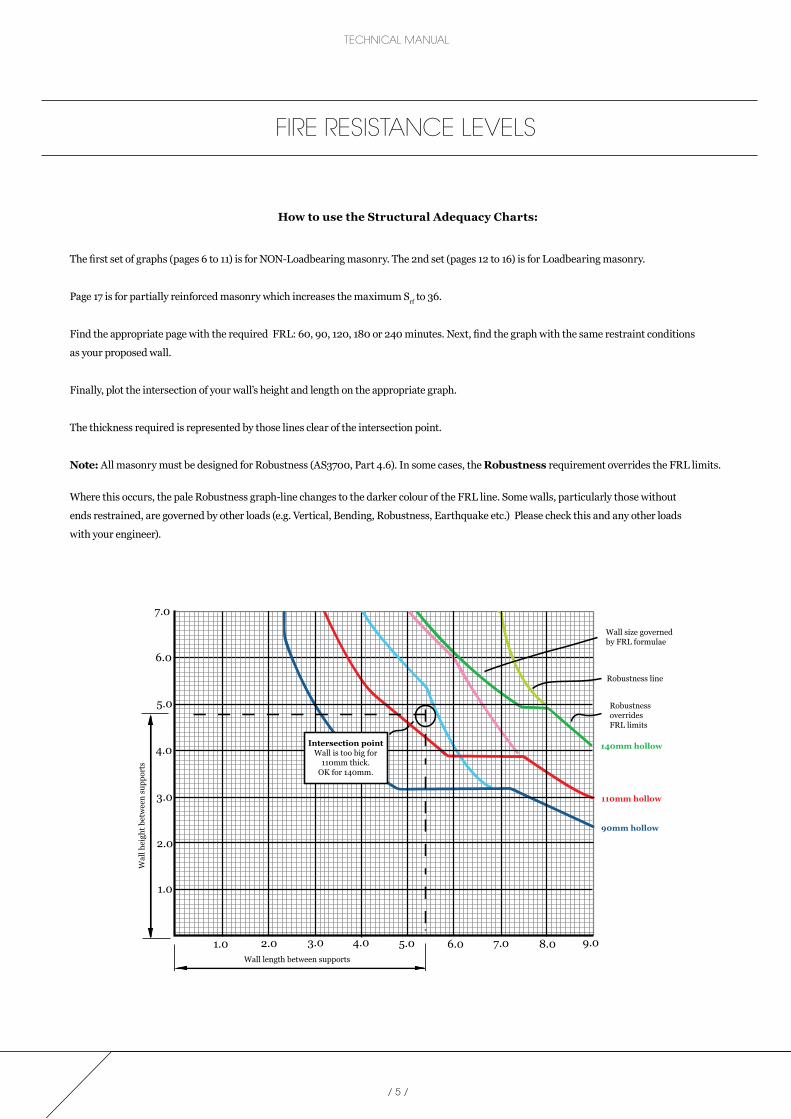
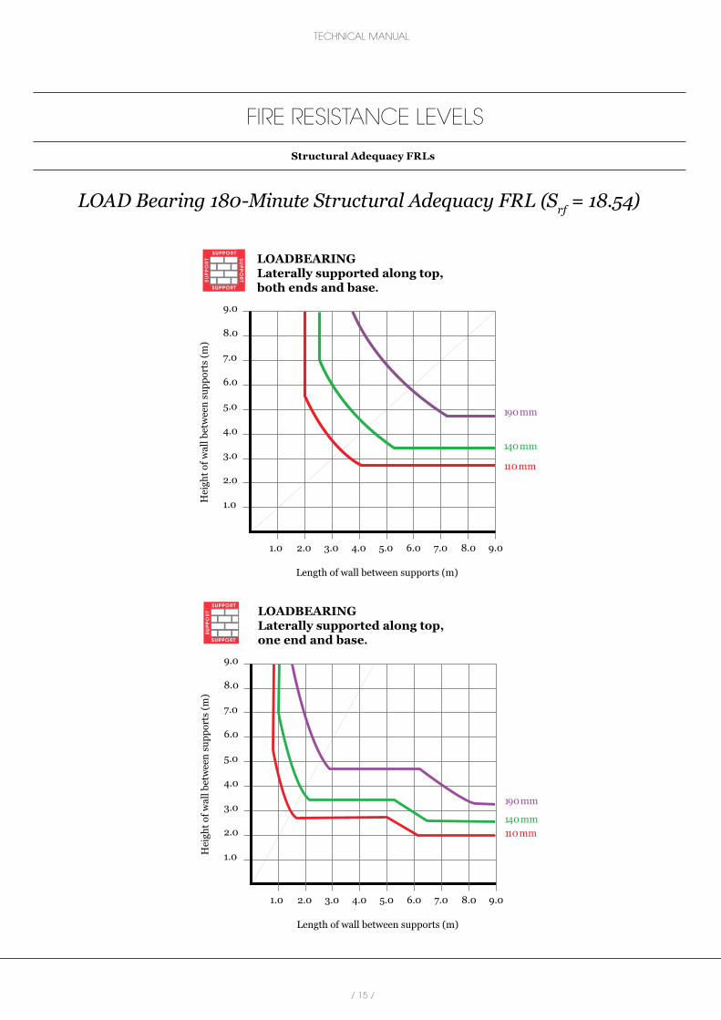
How to use the Structural Adequacy Charts:
The first set of graphs (pages 6 to 11) is for NON-Loadbearing masonry. The 2nd set (pages 12 to 16) is for Loadbearing masonry.
Page 17 is for partially reinforced masonry which increases the maximum Srf to 36.
Find the appropriate page with the required FRL: 60, 90, 120, 180 or 240 minutes. Next, find the graph with the same restraint conditions
as your proposed wall.
Finally, plot the intersection of your wall’s height and length on the appropriate graph.
The thickness required is represented by those lines clear of the intersection point.
Note: All masonry must be designed for Robustness (AS3700, Part 4.6). In some cases, the Robustness requirement overrides the FRL limits.
Where this occurs, the pale Robustness graph-line changes to the darker colour of the FRL line. Some walls, particularly those without
ends restrained, are governed by other loads (e.g. Vertical, Bending, Robustness, Earthquake etc.) Please check this and any other loads
with your engineer).
Wal
l hei
ght b
etw
een
supp
orts
Wall length between supports
1.0 2.0 3.0 4.0 5.0 6.0 7.0 8.0 9.0
1.0
2.0
3.0
4.0
5.0
6.0
7.0
Wall size governedby FRL formulae
Robustness line
Robustness overridesFRL limits
140mm hollow
110mm hollow
90mm hollow
Intersection pointWall is too big for
110mm thick.OK for 140mm.
FIRE RESISTANCE LEVELS

AUSTRALITE
FIRE RESISTANCE LEVELS
Structural Adequacy FRLs
60 & 90-Minute Structural Adequacy FRLs (Srf = 27.8) NB: Integrity (Srf 25.8 governs)
1.0
2.0
3.0
4.0
5.0
6.0
7.0
8.0
9.0
Hei
ght o
f wal
l bet
wee
n su
ppor
ts (m
)
1.0 2.0 3.0 4.0 5.0 6.0 7.0 8.0 9.0
Length of wall between supports (m)
NON-LOADBEARINGLaterally supported along top, both ends and base.
SUPPORT
SUPPORT
190 mm
140 mm
110 mm
SUPPORT
SUPPORT
Srf=27.8
90 mm
1.0
2.0
3.0
4.0
5.0
6.0
7.0
8.0
9.0
Hei
ght o
f wal
l bet
wee
n su
ppor
ts (m
)
1.0 2.0 3.0 4.0 5.0 6.0 7.0 8.0 9.0
Length of wall between supports (m)
NON-LOADBEARINGLaterally supported along top, one end and base.
SUPPORT
SUPPORT
190 mm140 mm110 mm
SUPPORT
Srf=27.8
90 mm
/ 6 /

/ 7 /
TECHNICAL MANUAL
FIRE RESISTANCE LEVELS
Structural Adequacy FRLs
120-Minute Structural Adequacy FRLs (Srf = 26.32) NB: Integrity (Srf 25.8 governs)
1.0
2.0
3.0
4.0
5.0
6.0
7.0
8.0
9.0
Hei
ght o
f wal
l bet
wee
n su
ppor
ts (m
)
1.0 2.0 3.0 4.0 5.0 6.0 7.0 8.0 9.0
Length of wall between supports (m)
NON-LOADBEARINGLaterally supported along top, both ends and base.
SUPPORT
SUPPORT
190 mm
140 mm
110 mm
SUPPORT
SUPPORT
Srf=26.32
90 mm
1.0
2.0
3.0
4.0
5.0
6.0
7.0
8.0
9.0
Hei
ght o
f wal
l bet
wee
n su
ppor
ts (m
)
1.0 2.0 3.0 4.0 5.0 6.0 7.0 8.0 9.0
Length of wall between supports (m)
NON-LOADBEARINGLaterally supported along top, one end and base.
SUPPORT
SUPPORT
190 mm140 mm110 mm
SUPPORT
Srf=26.32
90 mm

/ 8 /
AUSTRALITE
FIRE RESISTANCE LEVELS
Structural Adequacy FRLs
180-Minute Structural Adequacy FRLs (Srf = 23.3)
1.0
2.0
3.0
4.0
5.0
6.0
7.0
8.0
9.0
Hei
ght o
f wal
l bet
wee
n su
ppor
ts (m
)
1.0 2.0 3.0 4.0 5.0 6.0 7.0 8.0 9.0
Length of wall between supports (m)
NON-LOADBEARINGLaterally supported along top, both ends and base.
SUPPORT
SUPPORT
190 mm
140 mm
110 mm
SUPPORT
SUPPORT
Srf=23.3
90 mm
1.0
2.0
3.0
4.0
5.0
6.0
7.0
8.0
9.0
Hei
ght o
f wal
l bet
wee
n su
ppor
ts (m
)
1.0 2.0 3.0 4.0 5.0 6.0 7.0 8.0 9.0
Length of wall between supports (m)
NON-LOADBEARINGLaterally supported along top, both ends and base.
SUPPORT
SUPPORT
190 mm140 mm110 mm
SUPPORT
SUPPORT
Srf=23.3
90 mm

/ 9 /
TECHNICAL MANUAL
FIRE RESISTANCE LEVELS
Structural Adequacy FRLs
240-Minute Structural Adequacy FRLs (Srf = 21.16)
1.0
2.0
3.0
4.0
5.0
6.0
7.0
8.0
9.0
Hei
ght o
f wal
l bet
wee
n su
ppor
ts (m
)
1.0 2.0 3.0 4.0 5.0 6.0 7.0 8.0 9.0
Length of wall between supports (m)
NON-LOADBEARINGLaterally supported along top, both ends and base.
SUPPORT
SUPPORT
190 mm
140 mm
110 mm
SUPPORT
SUPPORT
Srf=21.16
90 mm
1.0
2.0
3.0
4.0
5.0
6.0
7.0
8.0
9.0
Hei
ght o
f wal
l bet
wee
n su
ppor
ts (m
)
1.0 2.0 3.0 4.0 5.0 6.0 7.0 8.0 9.0
Length of wall between supports (m)
NON-LOADBEARINGLaterally supported along top, one end and base.
SUPPORT
SUPPORT
190 mm140 mm110 mm
SUPPORT
Srf=21.16
90 mm
/ 10 /
AUSTRALITE
FIRE RESISTANCE LEVELS
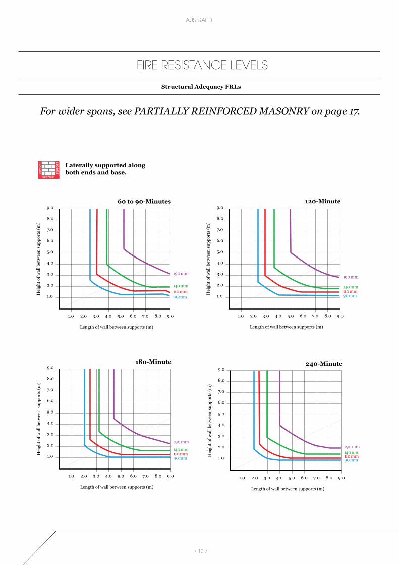
Structural Adequacy FRLs
For wider spans, see PARTIALLY REINFORCED MASONRY on page 17.
1.0
2.0
3.0
4.0
5.0
6.0
7.0
8.0
9.0
Hei
ght o
f wal
l bet
wee
n su
ppor
ts (m
)
1.0 2.0 3.0 4.0 5.0 6.0 7.0 8.0 9.0
Length of wall between supports (m)
Laterally supported alongboth ends and base.S
UPPORT
SUPPORT
190 mm
140 mm110 mm
60 to 90-Minutes
90 mm
SUPPORT
1.0
2.0
3.0
4.0
5.0
6.0
7.0
8.0
9.0H
eigh
t of w
all b
etw
een
supp
orts
(m)
1.0 2.0 3.0 4.0 5.0 6.0 7.0 8.0 9.0
Length of wall between supports (m)
190 mm
140 mm110 mm
120-Minute
90 mm
1.0
2.0
3.0
4.0
5.0
6.0
7.0
8.0
9.0
Hei
ght o
f wal
l bet
wee
n su
ppor
ts (m
)
1.0 2.0 3.0 4.0 5.0 6.0 7.0 8.0 9.0
Length of wall between supports (m)
190 mm140 mm110 mm
180-Minute
90 mm 1.0
2.0
3.0
4.0
5.0
6.0
7.0
8.0
9.0
Hei
ght o
f wal
l bet
wee
n su
ppor
ts (m
)
1.0 2.0 3.0 4.0 5.0 6.0 7.0 8.0 9.0
Length of wall between supports (m)
190 mm140 mm110 mm
240-Minute
90 mm

/ 11 /
TECHNICAL MANUAL
FIRE RESISTANCE LEVELS
Structural Adequacy FRLs
1.0
2.0
3.0
4.0
5.0
6.0
7.0
8.0
9.0
Hei
ght o
f wal
l bet
wee
n su
ppor
ts (m
)
1.0 2.0 3.0 4.0 5.0 6.0 7.0 8.0 9.0
Length of wall between supports (m)
Laterally supported alongone end and base.S
UPPORT
SUPPORT
190 mm140 mm110 mm
60 to 90-Minutes
90 mm
1.0
2.0
3.0
4.0
5.0
6.0
7.0
8.0
9.0H
eigh
t of w
all b
etw
een
supp
orts
(m)
1.0 2.0 3.0 4.0 5.0 6.0 7.0 8.0 9.0
Length of wall between supports (m)
190 mm140 mm110 mm
120-Minute
90 mm
1.0
2.0
3.0
4.0
5.0
6.0
7.0
8.0
9.0
Hei
ght o
f wal
l bet
wee
n su
ppor
ts (m
)
1.0 2.0 3.0 4.0 5.0 6.0 7.0 8.0 9.0
Length of wall between supports (m)
190 mm140 mm110 mm
180-Minute
90 mm1.0
2.0
3.0
4.0
5.0
6.0
7.0
8.0
9.0
Hei
ght o
f wal
l bet
wee
n su
ppor
ts (m
)
1.0 2.0 3.0 4.0 5.0 6.0 7.0 8.0 9.0
Length of wall between supports (m)
190 mm140 mm110 mm
240-Minute
90 mm

/ 12 /
AUSTRALITE
FIRE RESISTANCE LEVELS
Structural Adequacy FRLs
LOAD Bearing 60-Minute Structural Adequacy FRL (Srf = 22.93) NB: Integrity (Srf 21.14 governs)
1.0
2.0
3.0
4.0
5.0
6.0
7.0
8.0
9.0
Hei
ght o
f wal
l bet
wee
n su
ppor
ts (m
)
1.0 2.0 3.0 4.0 5.0 6.0 7.0 8.0 9.0
Length of wall between supports (m)
LOADBEARINGLaterally supported along top, both ends and base.
SUPPORT
SUPPORT
190 mm
140 mm
110 mm
SUPPORT
SUPPORT
Srf=22.93
1.0
2.0
3.0
4.0
5.0
6.0
7.0
8.0
9.0
Hei
ght o
f wal
l bet
wee
n su
ppor
ts (m
)
1.0 2.0 3.0 4.0 5.0 6.0 7.0 8.0 9.0
Length of wall between supports (m)
LOADBEARINGLaterally supported along top, one end and base.
SUPPORT
SUPPORT
190 mm
140 mm110 mm
SUPPORT
Srf=22.93

/ 13 /
TECHNICAL MANUAL
FIRE RESISTANCE LEVELS
Structural Adequacy FRLs
LOAD Bearing 90-Minute Structural Adequacy FRL (Srf = 21.31) NB: Integrity (Srf ≤ 21.14 governs)
1.0
2.0
3.0
4.0
5.0
6.0
7.0
8.0
9.0
Hei
ght o
f wal
l bet
wee
n su
ppor
ts (m
)
1.0 2.0 3.0 4.0 5.0 6.0 7.0 8.0 9.0
Length of wall between supports (m)
LOADBEARINGLaterally supported along top, both ends and base.
SUPPORT
SUPPORT
190 mm
140 mm
110 mm
SUPPORT
SUPPORT
Srf=21.31
1.0
2.0
3.0
4.0
5.0
6.0
7.0
8.0
9.0
Hei
ght o
f wal
l bet
wee
n su
ppor
ts (m
)
1.0 2.0 3.0 4.0 5.0 6.0 7.0 8.0 9.0
Length of wall between supports (m)
LOADBEARINGLaterally supported along top, one end and base.
SUPPORT
SUPPORT
190 mm
140 mm110 mm
SUPPORT
Srf=21.31

/ 14 /
AUSTRALITE
FIRE RESISTANCE LEVELS
Structural Adequacy FRLs
LOAD Bearing 120-Minute Structural Adequacy FRL (Srf = 20.16)
1.0
2.0
3.0
4.0
5.0
6.0
7.0
8.0
9.0
Hei
ght o
f wal
l bet
wee
n su
ppor
ts (m
)
1.0 2.0 3.0 4.0 5.0 6.0 7.0 8.0 9.0
Length of wall between supports (m)
LOADBEARINGLaterally supported along top, both ends and base.
SUPPORT
SUPPORT
190 mm
140 mm
110 mm
SUPPORT
SUPPORT
Srf=20.16
1.0
2.0
3.0
4.0
5.0
6.0
7.0
8.0
9.0
Hei
ght o
f wal
l bet
wee
n su
ppor
ts (m
)
1.0 2.0 3.0 4.0 5.0 6.0 7.0 8.0 9.0
Length of wall between supports (m)
LOADBEARINGLaterally supported along top, one end and base.
SUPPORT
SUPPORT
190 mm
140 mm110 mm
SUPPORT
Srf=20.16
/ 15 /
TECHNICAL MANUAL
FIRE RESISTANCE LEVELS
Structural Adequacy FRLs
LOAD Bearing 180-Minute Structural Adequacy FRL (Srf = 18.54)
1.0
2.0
3.0
4.0
5.0
6.0
7.0
8.0
9.0
Hei
ght o
f wal
l bet
wee
n su
ppor
ts (m
)
1.0 2.0 3.0 4.0 5.0 6.0 7.0 8.0 9.0
Length of wall between supports (m)
LOADBEARINGLaterally supported along top, both ends and base.
SUPPORT
SUPPORT
190 mm
140 mm
110 mm
SUPPORT
SUPPORT
Srf=18.54
1.0
2.0
3.0
4.0
5.0
6.0
7.0
8.0
9.0
Hei
ght o
f wal
l bet
wee
n su
ppor
ts (m
)
1.0 2.0 3.0 4.0 5.0 6.0 7.0 8.0 9.0
Length of wall between supports (m)
LOADBEARINGLaterally supported along top, one end and base.
SUPPORT
SUPPORT
190 mm
140 mm110 mm
SUPPORT
Srf=18.54

/ 16 /
AUSTRALITE
FIRE RESISTANCE LEVELS
Structural Adequacy FRLs
LOAD Bearing 240-Minute Structural Adequacy FRL (Srf = 17.39)
1.0
2.0
3.0
4.0
5.0
6.0
7.0
8.0
9.0
Hei
ght o
f wal
l bet
wee
n su
ppor
ts (m
)
1.0 2.0 3.0 4.0 5.0 6.0 7.0 8.0 9.0
Length of wall between supports (m)
LOADBEARINGLaterally supported along top, both ends and base.
SUPPORT
SUPPORT
190 mm
140 mm
110 mm
SUPPORT
SUPPORT
Srf=17.39
1.0
2.0
3.0
4.0
5.0
6.0
7.0
8.0
9.0
Hei
ght o
f wal
l bet
wee
n su
ppor
ts (m
)
1.0 2.0 3.0 4.0 5.0 6.0 7.0 8.0 9.0
Length of wall between supports (m)
LOADBEARINGLaterally supported along top, one end and base.
SUPPORT
SUPPORT
190 mm
140 mm110 mm
SUPPORT
Srf=17.39

/ 17 /
TECHNICAL MANUAL
FIRE RESISTANCE LEVELS
Structural Adequacy FRLs
Partially Reinforced Masonry
Structural Adequacy FRL = 240 minutesSrf ≤ 36 (AS3700:2011, Table 6.1)
Robustness = 0.5kPa (from CMAA Design Guide, Horizontal Loads)
Wall Height
Reinforced Core Spacing One 16mm Reinforcement Bar
t = 140mm t = 190mm
3.0m 7.6m N/A
4.0m 4.4m 6.4m
5.0m 2.8m 4.0m
6.0m 2.0m 2.8m
7.0m Srf > 36 2.0m
8.0m - 1.4m
Wall Height
Reinforced Bond Beam Spacing One 16mm Reinforcement Bar
t = 140mm t = 190mm
3.0m 4.4m 5.8m
4.0m 3.8m 5.0m
5.0m 3.4m 4.4m
6.0m Srf > 36 4.0m
7.0m - Srf > 36
8.0m - -
Disclaimer: Please note: It is the designer’s responsibility to allow for the effects of control joints; chases; openings; the strength and stiffness of connectors & supports, in addition to consideration of loads and masonry properties.
SUPPORT
SUP
PO
RT
SUP
PO
RT
Core reinforced with one N16
Bond beam reinforced with one N16
SUPPORT
SUPPORT
Bond
bea
m sp
acin
g
SUPPORT
SUP
PO
RT
SUP
PO
RT
Core reinforced with one N16
Bond beam reinforced with one N16
SUPPORT
SUPPORT
Bond
bea
m sp
acin
g

/ 18 /
AUSTRALITE
ACOUSTIC RATINGSThis section describes the measurement of acoustic ratings, the BCA requirements for residential buildings and details of research and development of successful wall systems for Denseweight and Lightweight masonry.
Rw (weighted sound reduction index) “Rw” is a type of average of low to high frequencies, calculated from a wall’s sound transmission losses over 16 frequencies. It is measured in decibels (dB).
Low frequency sound waves (e.g. from a bass guitar) are large and intrusive. Their sound transmission loss is below Rw (average). At the other end of the scale, high frequency sound waves (e.g. violin, piccolo) are short wave, less intrusive and their sound transmission loss is above average.
A typical sound rating is expressed as Rw 55 (-1; -5). The first figure in the brackets is “C” which indicates irregular performance in the high frequencies. It is not addressed in the BCA. The second figure in the brackets is “Ctr” and is essential in BCA requirements for party walls.
Ctr (low frequency spectrum adaptor) “Ctr” is an indicator of how much lower the wall’s performance would be if the noise source was mainly low frequency. Ctr is a negative number. The sound rating above of Rw 55 dB with a Ctr of -5 gives Rw + Ctr = 50.
Party Walls:
These walls are described in the BCA, Part F5, as walls that “separate sole-occupancy units” (also known as inter-tenancy walls). This includes townhouses, high-rise home units, three-storey flats, hotels and similar residential buildings. Except for Class 9c buildings (aged care units); party walls require a minimum sound rating of Rw + Ctr 50.
A party wall that separates one sole-occupancy unit’s wet area (a bathroom, laundry, kitchen etc.) from a habitable room in another sole-occupancy unit is required to be of discontinuous construction .

/ 19 /
TECHNICAL MANUAL
Discontinuous Construction:
The BCA describes discontinuous construction as “a wall having a minimum 20mm cavity between 2 separate leaves”. See following diagrams for details. Where the 2 separate leaves are both masonry, the BCA allows resilient wall ties “if required”. As they are rarely required, their omission will not only save money but improve the acoustic performance of cavity (double-leaf masonry) walls.
Discontinuous construction is also required where a wall separates a sole-occupancy unit from a plant room or lift shaft.
Corridor Walls:
Walls that separate a sole-occupancy unit from a plant room, lift shaft, corridor, stair, foyer or similar public area, require a minimum sound rating of Rw 50. There is no Ctr adjustment. See following diagrams for details.
Walls that separate a sole-occupancy unit from a plant room or lift shaft are required to be of discontinuous construction: e.g: the independent stud system.
Research and Development:
In 2011, the National Acoustic Laboratory tested 140mm thick 15-01 masonry. Test N° 2538-2, with a 64mm independent stud wall system, achieved Rw + Ctr 50 (the BCA requirement for walls separating home units).
This wall also meets the BCA requirement to resist the transmission of impact-generated sound wherever an inter-tenancy wall separates a wet area (bathroom / laundry / kitchen etc) from a habitable room.
These and previous tests provided data for Day Design to form opinions on the performance of other types of masonry as follows.
The 15-01 masonry units achieve the BCA fire rating requirements for low to high-rise home unit walls before adding any lining system.
ACOUSTIC RATINGS

/ 20 /
AUSTRALITE
ACOUSTIC RATINGS
90mm Masonry Systems - Block Codes: 10-01DW & 10-01LW
Corridor Wall: Rw 50 (including unit to stairs, unit to foyer)
Party Wall: Rw + Ctr 50NB: Wall ties must be RESILIENT, to comply with discontinuous construction.
Party Wall: Rw + Ctr 50NB: Wall ties must be RESILIENT, to comply with discontinuous construction.
13mm standard-core plasterboard,daub-fixed
2 layers 13mm standard-core plasterboard on28mm furring channel on standard clipsMinimum cavity: 30mmwith25mm Glasswool or 30mm Polyester in cavity
10mmcement render
1 layer 13mm Sound Rated plasterboard
on
70mm timber stud, 20mm clear of masonry
with
R1.5 Glasswool or Polyester
164mm
203mm
2 layers 10mm std plasterboard on70mm timber stud, 20mm clear of masonrywithR1.5 Glasswool or Polyester
Bare wall Rw 40
Bare wall
200mm

/ 21 /
TECHNICAL MANUAL
ACOUSTIC RATINGS
110mm Masonry Systems - Codes: 12-01DW & 12-01LW
Corridor Wall: Rw 50 (including unit to stairs, unit to foyer)
Party Wall: Rw + Ctr 50NB:Not suitable for wet-to-dry areas. See Discontinuous detail below.
Party Wall: Rw + Ctr 50Discontinuous Construction. Suitable for all Party Walls.
13mm standard-core plasterboard,daub-fixed
13mm standard-core plasterboard on28mm furring channel on resilient mounts. Minimum cavity: 30mmwith25mm Glasswool or30mm Polyester in cavity 171mm
13mm standard-core plasterboard,daub-fixed
2 layers of13mm standard-core plasterboardon28mm furring channel on resilient mounts. Minimum cavity: 50mmwith50mm Glasswool or50mm Polyester in cavity
204mm
2 layers 10mm std plasterboard
13mm Standard-core plasterboard on64mm steel studs20mm clear of masonry with75mm Glasswool or65mm Polyester
232mm
Bare wall Rw 42

/ 22 /
AUSTRALITE
ACOUSTIC RATINGS
140mm Masonry Systems - Codes: 15-01DW & 15-01LW
Corridor Wall: Rw 50 (including unit to stairs, unit to foyer)
Party Wall: Rw + Ctr 50NB:Not suitable for wet-to-dry areas. See Discontinuous detail below.
Party Wall: Rw + Ctr 51
Discontinuous Construction. Suitable for all Party Walls.
If wall ties are required, they must be resilient type. (No ties is better).
No lining required13mm standard-core plasterboard on28mm furring channel on standard clipsMinimum cavity: 30mm
183mm
13mm standard-core plasterboard,daub-fixed
2 layers of13mm standard-core plasterboardon28mm furring channel on standard clipsMinimum cavity: 50mmwith50mm Glasswool or 50mm Polyester in cavity
234mm
13mm standard-core plasterboard,daub-fixed
13mm Standard-core plasterboard
on64mm steel studs20mm clear of masonry with75mm Glasswool or65mm Polyester 255mm
Bare wall Rw 43

/ 23 /
TECHNICAL MANUAL
ACOUSTIC RATINGS
140mm Grouted Systems - Block Code: 15-48 DW & 15-48 LW
Corridor Wall: Rw 50 (including unit to stairs, unit to foyer)
Party Wall: Rw + Ctr 51 (both options)NB: Not suitable for wet-to-dry areas. See Discontinuous detail below.
Party Wall: Rw + Ctr 52Discontinuous Construction. Suitable for all Party Walls.
If wall ties are required, they must be resilient type. (No ties is better).
No lining required
140mm
13mm standard-core plasterboard,daub-fixed
2 layers of13mm standard-core plasterboardon28mm furring channel on standard clips. Minimum cavity 30mmwith25mm Glasswool or30mm Polyester in cavity 214mm
13mm standard-core plasterboard on28mm furring channel on standard clipsMinimum cavity: 50mmwith50mm Glasswool or50mm Polyester in cavity 221mm
13mm standard-core plasterboard,daub-fixed
13mm Standard-core plasterboard on64mm steel studs20mm clear of masonry with75mm Glasswool or65mm Polyester 255mm
13mm standard-core plasterboard,daub-fixed

/ 24 /
AUSTRALITE
ACOUSTIC RATINGS
190mm Masonry Systems - Codes: 20-01DW & 20-01LW
Corridor Wall: Rw 50 (including unit to stairs, unit to foyer)
Party Wall: Rw + Ctr 50NB: Not suitable for wet-to-dry areas. See Discontinuous detail below.
Party Wall: Rw + Ctr 50Discontinuous Construction. Suitable for all Party Walls.
If wall ties are required, they must be resilient type. (No ties is better).
13mm standard-core plasterboard on28mm furring channel on standard clipsMinimum cavity: 30mm
251mm
13mm standard-core plasterboard,daub-fixed
2 layers of13mm standard-core plasterboardon28mm furring channel on standard clipsMinimum cavity: 30mmwith25mm Glasswool or30mm Polyester in cavity
264mm
13mm standard-core plasterboard,daub-fixed
13mm Standard-core plasterboard on64mm steel studs20mm clear of masonry with75mm Glasswool or65mm Polyester
305mm
Bare wall Rw 45

/ 25 /
TECHNICAL MANUAL
ACOUSTIC RATINGS
190mm Grouted Systems - Block Code: 20-48 DW & 20-48 LW
Party Wall: Rw + Ctr 50NB: Not suitable for wet-to-dry areas. See Discontinuous detail below.
Party Wall: Rw + Ctr 52Discontinuous Construction. Suitable for all Party Walls.
If wall ties are required, they must be resilient type. (No ties is better).
Corridor Wall: Rw 50 (including unit to stairs, unit to foyer)
No lining required
190mm
13mm standard-core plasterboard,daub-fixed
13mm standard-core plasterboard on28mm furring channel on standard clips. Minimum cavity 30mmwith25mm Glasswool or30mm Polyester in cavity 251mm
13mm standard-core plasterboard,daub-fixed
13mm Standard-core plasterboard on64mm steel studs20mm clear of masonry with75mm Glasswool or65mm Polyester 305mm

/ 26 /
AUSTRALITE
THERMAL MASSinformation
Thermal mass (also known as thermal inertia or thermal capacitance) is the ability of a material to retain heat when subjected
to a temperature differential. Denseweight concrete has high thermal mass. If a building with high thermal mass is subject
to a heating and cooling cycle that crosses the comfort zone, the material with high thermal mass will maintain its heat energy
for an extended period. In practical terms, in summer a building with dense concrete floors and walls will remain relatively
cool during the day time, while in winter the same building will remain relatively warm.
PROPERTIES OF CONCRETE MASONRY
• Concrete masonry has moderate thermal insulation properties (controlling the passage of applied heat out of the building in winter
or atmospheric heat into the building in summer). It has good thermal mass (slowly releasing stored heat in winter and slowly
absorbing atmospheric heat in summer) It is a relatively inexpensive building material, providing attractive life-cycle costings,
particularly when the building life is relatively short. The amount of energy used to produce concrete masonry is relatively low when
compared to most other building materials. Generally, materials that are good thermal insulators are incapable of supporting heavy
loads. Conversely, most good load-supporting materials are poor insulators. Concrete masonry is a notable exception to these
general rules.
• Its good insulating qualities are derived primarily from the minute voids in the concrete of the units. In general, it will be found that
masonry units of lower density concrete will have higher thermal resistance because of their greater voids content. Thermal
resistance is generally improved by substituting lightweight aggregates for dense aggregates in the masonry concrete. It may be
further improved by filling the cores of walls of hollow blocks with granular insulating materials such as perlite or vermiculite.
Where cores are filled in this way, measures must be taken to prevent entry of moisture to the wall cores and the core-filling
material. Such precautions include the use of cavity wall construction, moisture- resistant external coatings and the preventing
of water entry by good flashing and weathering practice *
* Source: CMAA MA55 (www.cmaa.com.au)

/ 27 /
TECHNICAL MANUAL
BCA SPECIFICATION J1.5 WALL CONSTRUCTION
* ADD INSULATION TO ACHIEVE THE REQUIRED R-VALUE
Item Item Description R-Value
1. Outdoor air film (7m/s) 0.04
2. Australite 90mm thick block 0.16
3.Cavity and airpsace (115 to 140mm, made up of 90mm stud + 25mm to 50mm air-space non-reflective and ventilated)*
0.17
4. Plasterboard, gypsum (10mm, 880kg/m3) 0.06
5. Indoor air film (still air) 0.12
Total R-Value before adding insulation 0.55
Item Item Description R-Value
1. Outdoor air film (7m/s) 0.04
2. Australite 90mm thick block 0.16
3. Airpsace (20 to 40mm non-reflective and ventilated) 0.17
4. Australite 90mm thick block 0.16
5.Airspace (20mm to 35mm, non-reflective and unventilated)* 0.17
6. Plasterboard, gypsum (10mm, 880kg/m3) 0.06
7. Indoor air film (still air) 0.12
Total R-Value before adding insulation 0.88
1
2
3
4
5
1
2
3
4
5
1
2
3
4
5
1
2
3
4
5
1
2
3
4
5
1
2
3
4
5
1
2
3
4
5
1
2
3
4
5
1
2
3
4
5
6
7
1
2
3
4
5
1
2
3
4
5
1
2
3
4
5
1
2
3
4
5
1
2
3
4
5
1
2
3
4
5
1
2
3
4
5
1
2
3
4
5
1
2
3
4
5
6
7
Masonry Veneer 25mm to 50mm cavity, 10mm internal plaster on 90mm stud frame
Cavity Masonry 20mm to 50mm cavity, 10mm internal plaster on battens or furring channels

/ 28 /
AUSTRALITE
BCA SPECIFICATION J1.5 WALL CONSTRUCTION
* ADD INSULATION TO ACHIEVE THE REQUIRED R-VALUE
110mm Australite hollow block with internal plaster on battens or furring channels
Item Item Description R-Value
1. Outdoor air film (7m/s) 0.04
2. 110mm Australite concrete block 0.18
3. Airpsace (20 to 40mm batterns or furring non-reflective and ventilated)* 0.17
4. Plasterboard, gypsum (10mm, 880kg/m3) 0.06
5. Indoor air film (still air) 0.12
Total R-Value before adding insulation 0.57
1
2
3
4
5
1
2
3
4
5
1
2
3
4
5
1
2
3
4
5
1
2
3
4
5
1
2
3
4
5
1
2
3
4
5
1
2
3
4
5
1
2
3
4
5
6
7
Item Item Description R-Value
1. Outdoor air film (7m/s) 0.04
2. 140mm Australite concrete block 0.21
3.
Cavity and airpsace (115 to 140mm, made up of 90mm stud on batterns or furring channels + 25mm to 50mm airspace non-reflective and ventilated)*
0.17
4. Plasterboard, gypsum (10mm, 880kg/m3) 0.06
5. Indoor air film (still air) 0.12
Total R-Value before adding insulation 0.60
140mm Australite hollow concrete block with internal plaster on battens or furring channels
1
2
3
4
5
1
2
3
4
5
1
2
3
4
5
1
2
3
4
5
1
2
3
4
5
1
2
3
4
5
1
2
3
4
5
1
2
3
4
5
1
2
3
4
5
6
7

TECHNICAL MANUAL
/ 29 /
140mm Australite hollow concrete block with internal plaster on battens or furring channels
BCA SPECIFICATION J1.5 WALL CONSTRUCTION
190mm Australite hollow concrete block with internal plaster on battens or furring channels
Item Item Description R-Value
1. Outdoor air film (7m/s) 0.04
2. 190mm Australite hollow concrete block 0.22
3.Airpsace (20 to 40mm, non-reflective and ventilated)* 0.17
4. Plasterboard, gypsum (10mm, 880kg/m3) 0.06
5. Indoor air film (still air) 0.12
Total R-Value before adding insulation 0.61
1
2
3
4
5
1
2
3
4
5
1
2
3
4
5
1
2
3
4
5
1
2
3
4
5
1
2
3
4
5
1
2
3
4
5
1
2
3
4
5
1
2
3
4
5
6
7
* ADD INSULATION TO ACHIEVE THE REQUIRED R-VALUE

/ 30 /
AUSTRALITE
NOTES

NOTES
/ 31 /
TECHNICAL MANUAL
STYLE AND FUNCTION
www.australmasonry.com.au1300 masonry (1300 627 667)
follow brickworks building products on
DESIGN CENTRES
HEAD OFFICE
DESIGN STUDIOS
XX
xx xx xx
XX
xx xx xx
XX
xx xx xx
XX
xx xx xx
XX
xx xx xx
XX
xx xx xx
XX
xx xx xx
AM 7898 brownink.com.au 08/2017


![NATURAL BLACK GLASS AUSTRALITE FRAGMENTS · NATURAL BLACK GLASS RESEMBLING AUSTRALITE FRAGMENTS By George Baker, M.Sc. Searches for australites in soutli-westeri] Victoria, have revealed](https://img.dokumen.tips/doc/110x75/5f0899767e708231d422ce5c/natural-black-glass-australite-fragments-natural-black-glass-resembling-australite.jpg)