Embed Size (px)
Citation preview

AUSTRALIAN HARDWOOD AND CYPRESS 1
AP
PL
IC
AT
IO
N
GU
ID
E
E X P R E S S E D H A R D W O O D S T R U C T U R E S
SCOPEThis guide provides ideas and designinformation to assist in the development ofexpressed native timber structures in buildings.Basic information on how to determinestructural form, typical connections and timberuse are included.
EXPRESSED INTERNAL STRUCTURESThe use of hardwoods as expressed internalstructural elements represents the most‘complete’ application of hardwood inconstruction. The three major attributes ofAustralian hardwood- high strength to weight,durability and beauty are all ‘expressed’ in thefinal result.
Combined with the natural fire resistanceproperties of many hardwoods, these attributesmake high value applications, such asstructures for public buildings, a natural choicefor the material.
Post and beam structure
Expressed Hardwood StructuresTrusses, Cathedral Ceilings, Post and Beam Frames
The success of specialist, non-domesticstructures depends on the fusion of design andengineering disciplines. The structural form isdependant as much on the desired feel of thespace as it is on structural requirements.Australian timbers offer a wide range of optionsand may also be successfully blended withother building materials such as steel, concreteand glass.
POPULAR STRUCTURAL SYSTEMSFOR EXPRESSED CONSTRUCTION
Post and Beam FramesProbably the oldest structural system, yet stillfavoured by today’s designers. Traditionallyusing large end-section timbers, post and beamstructures have been favoured for buildingeverything from shearing sheds to eight storeycity buildings. Many examples over 100 yearsold still stand behind their nineteenth centurybrick facades throughout our major cities.

AP
PL
IC
AT
IO
N
GU
ID
E
AUSTRALIAN HARDWOOD AND CYPRESS2
E X P R E S S E D H A R D W O O D S T R U C T U R E S
COMMON EXPRESSED ROOFSTRUCTURES(Refer to Figure 2)
• Simple pitched roof – using rafters spanningbetween ridge beam, intermediate beamsand wall.
• Coupled pitched roof – using collar-ties.
• Trusses supporting purlins and rafters.
• Trusses supporting purlin battens.
Roofing
Ceiling over rafter
Rafter
Roof beam
Flooring
Multiple memberbeam
Multiple memberpost
Concealedpost shoe
Multiple memberpost
Joists
Batten
Figure 1: Typical multiple member post andbeam construction
Although large end-section timbers are stillavailable to order, today’s precision milled, kilndried hardwoods are ideal for multiple memberpost and beam structures. The use of timber totimber connection systems enables slim, robustand beautiful structures to be constructedpractically and economically. Where large endsections are required, glue laminated hardwoodoffers almost unlimited potential.
Simple pitched roof
Coupled pitched roofusing collar-ties
Trusses supporting purlins and rafters
Trusses supporting purlin battens
Figure 2: Common expressed roof structures

AUSTRALIAN HARDWOOD AND CYPRESS 3
AP
PL
IC
AT
IO
N
GU
ID
E
E X P R E S S E D H A R D W O O D S T R U C T U R E S
Insulation
Ceiling liningover rafters
Triple gripor similar
Wall lining
Batten
Cladding
Blocking
Metal deck roofing
Batten depth commonly determined by insulation requirements. Alternatively use counter batten and top batten
Rafter
Rafter
Insulationbetween rafters
Ceiling liningbelow rafter
Eaves liningbelow rafters
Intermediate beam
Triple gripor similar
Wall lining
Batten
Cladding
Metal deck roofing
Figure 4: Ceiling below rafters
Ceiling Below RaftersAs rafters are concealed within the ceilinglining and supporting beams, trusses or otherprimary structural members are expressed. Thedepth of the rafters is available for insulation,and ceiling installation is done after the roofcovering. Concealing of rafter/supportconnection is still required for best appearance.Refer to Figure 4.
Connections for these members are simple,and utilise nail requirements akin to site-pitched roof construction. Structural detailingmay make use of the previously mentionedpost and beam construction. As shown inFigure 2, this involves a pitching beam andridge beam to support the rafters. In addition,intermediate beams may be necessary toreduce the span of long rafters.
PITCHED ROOF STRUCTURESOften used in conjunction with a post and beamsystem for efficient construction. Can workequally well with conventional stud framingsupport. It should be noted that where the raftersare not ‘tied’ together via conventional ceilingjoists, an alternative must be considered to resistthe spreading of the rafters under roof loads. Toprevent this, a collar tie must be included, andrafter sizes are generally increased to retainrigidity in the structure. If this increase in size isundesirable, then an extra tie can be locatednear the base of the rafters, and this can bemade of timber, wire or steel rod.
Simple Pitched RoofThe most common method of achieving a so-called ‘cathedral ceiling’ uses rafters simplyspanning between ridge and intermediate beamsand external walls. Ceiling linings can be fixedto either the top or bottom face of the rafters.
Ceiling Above RaftersHas the advantage of concealing joins in ceilingmaterials – commonly lining boards, plywoodor cement based panel products. If using liningboards, shorter lengths can be utilised.Progressive cover needs to be maintained toprevent water damage and staining.
Fixing of rafters to beams also needs carefuldetailing, as common methods such as the useof nail plate connectors are not appropriate.The use of long (up to 150mm) type 17 screwsand coach screws are common methods ofachieving required tie down. AS1684 shouldbe utilised to calculate the loads to be resisted.Assistance can be sought from structuralengineers for specific requirements.
The depth of battens is determined largely byinsulation requirements. A 70 x 45mm on edgeis common. Alternatively, counter battens overrafters with standard battens over can be used.Refer to Figure 3.
Figure 3: Ceiling above rafters

AP
PL
IC
AT
IO
N
GU
ID
E
AUSTRALIAN HARDWOOD AND CYPRESS4
E X P R E S S E D H A R D W O O D S T R U C T U R E S
Howe
Pratt
King post
Palladian
Fan
Fink
ARCHITECTURAL TRUSSESArchitectural trusses are often used as part of a‘cathedral ceiling’ system. Aesthetically, thispart of the structure creates an eye-catchingappearance, and typical options are shown inFigure 5. Many of these designs, were patentedduring the 19th century, and still bear thename of the original designers e.g., Pratt,Howe etc.
Figure 5: Typical truss designs
Figure 7: Scissors truss configuration
Figure 6: Truss with raised bottom chords
In trying to maximise the visual impact oftrusses, it is common to space them in theorder of 3 to 6 metres apart, to distinguishthem as individual features. To make thispossible, purlins are used to span betweentrusses for the purpose of supporting in-fillrafters (i.e. between the trusses). As a result, thetruss chords (top) take extra bending from thepurlin loads. This can require larger top chordsthan desired, and if there is a need to reducethis size, the problem can be solved byincorporating more webs into the truss (i.e.more top chord support), thus allowing asmaller chord to be used.
Some truss designs involve situations where thebottom chord is raised to give a greater feelingof space – as shown in Figure 6. The maindisadvantage of this type of truss is that largerand stronger members are required to dealwith flexure in the top chord, resulting fromthe acquired loads brought about by the raisedbottom chord. As a result, care must be takento ensure that the desired appearance andbudget can still be is attained. If appropriate, amore attenuated option is the scissor truss – asshown in Figure 7. It uses the inner membersto create ties that are always in tension - evenunder wind reversal loads – these create anotional ceiling line and may be made fromtimber, cable or steel rod.
Trusses get their strength via triangulation,which bands elements together to act instructurally advantageous ways. For instance,each member can be assigned to work in anetwork of tension and compression members,and by doing this, greater structural efficiencyis possible. For the types of trusses describedabove, compression members often dictate thesize of the elements, and for this reason,designs that have short compression members,or restraint against lateral buckling, aregenerally more efficient than trusses with longcompression members.

AUSTRALIAN HARDWOOD AND CYPRESS 5
AP
PL
IC
AT
IO
N
GU
ID
E
E X P R E S S E D H A R D W O O D S T R U C T U R E S
CONNECTIONSConnections greatly influence appearance,economy and ease of construction. A key issueis the number of members intersecting at aconnection (i.e. truss nodes). For instance,there are various configurations that canbroadly be grouped into: single web and singlechord connections; double web and singlechord connections; single web and doublechord connections; and more complexconnections. A number of these options areshown in Figure 8.
An eccentric joint where care needs to be exercised in thedesign (refer Ozeiton and Baird)
A five member joint where the central web load travels via theconnecter and the chord members to reach the outer (inclined)webs. This means that the load is applied close to 90º to thegrain
A seven member arrangement as could be employed in aPalladian or fan truss
Figure 9: Interleaved plate connection
Steel Plates used with Nails or ScrewsTruss members are commonly joined withmetal plates that incorporate nails or screws.Nails are the most economical option, and arecommonly used in mass production situations.Here, ‘nail plates’ are pressed into place, andthe many small nails serve to distribute theload over a broad area. As a result, there isbetter transfer of stresses, reduced impact fromimperfections such as knots, and less concernabout using low strength timbers. In contrast,bolts concentrate the load, and are thereforestructurally less efficient.
In some cases where aesthetics dictate, greatereffort may be made to conceal the plateconnectors. Here, the plates may be cut intoinsertion slots in the webs and chords - asshown in Figure 9. This also provides anefficient structural design. During fabrication, itis also useful to take advantage of machinedriven nails which can penetrate steel platesup to 2mm in thickness . For thicker plates,screws may be necessary, and can beefficiently applied using self-drilling screws.Screws are typically Type 17 wood screws –often termed ‘batten screws’ – and come in anumber of head types to facilitate driving. Theability to drive these screws is somewhatdependent on the depth and density of thesubstrate timber. For instance, there arelimitations with the use of self-drilling screwsin hardwood, and in such instances, pre-drilling is required.
Figure 8. Alternative truss connection systems
AP
PL
IC
AT
IO
N
GU
ID
E
AUSTRALIAN HARDWOOD AND CYPRESS6
E X P R E S S E D H A R D W O O D S T R U C T U R E S
Bolts with Steel Side PlatesUnder this scenario, thick steel side plates orgussets are used in conjunction with bolts totransfer the load. Here, gussets may becomelong and obtrusive due to the need to spacebolts far enough apart to spread the load.Plates can also be expensive to fabricate as theplate must mimic the complex shapes of themember intersections. If appropriate, a wayaround this issue is to use hidden plates – asdiscussed previously.
Bolts and Timber ConnectionsIn traditional trusses, connections are oftenmade using bolts which hold multiple chordand web components together like a pin joint(Refer to Figure 8). Though common in olderstructures, these types of connections havedifficulty in developing sufficient rigidity, andalso cause eccentric loading. It is hard toprevent this, but the usual method of managingthe problem is to make a more compact jointby using a large number of small diameterbolts. As a result, this method tends to be moreexpensive than the steel plate optionsdiscussed previously.
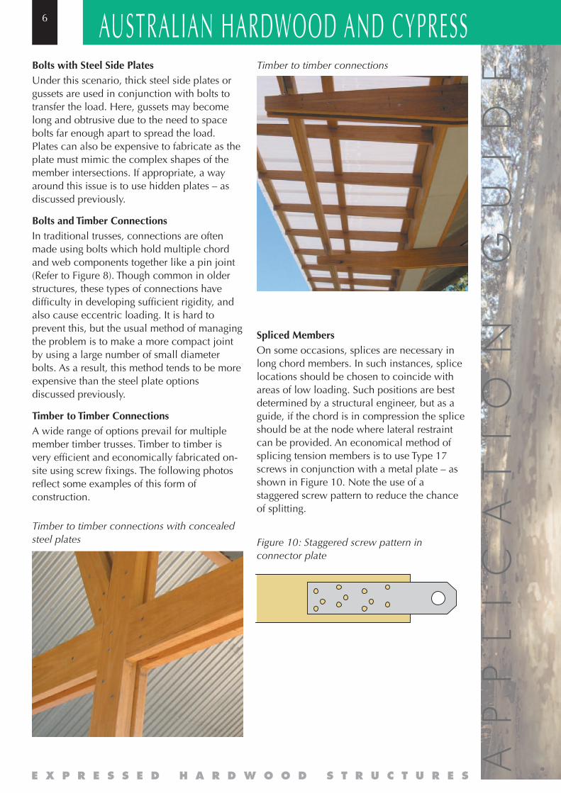
Timber to Timber ConnectionsA wide range of options prevail for multiplemember timber trusses. Timber to timber isvery efficient and economically fabricated on-site using screw fixings. The following photosreflect some examples of this form ofconstruction.
Timber to timber connections with concealedsteel plates
Timber to timber connections
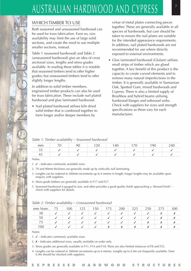
Spliced MembersOn some occasions, splices are necessary inlong chord members. In such instances, splicelocations should be chosen to coincide withareas of low loading. Such positions are bestdetermined by a structural engineer, but as aguide, if the chord is in compression the spliceshould be at the node where lateral restraintcan be provided. An economical method ofsplicing tension members is to use Type 17screws in conjunction with a metal plate – asshown in Figure 10. Note the use of astaggered screw pattern to reduce the chanceof splitting.
Figure 10: Staggered screw pattern inconnector plate
AUSTRALIAN HARDWOOD AND CYPRESS 7
AP
PL
IC
AT
IO
N
GU
ID
E
E X P R E S S E D H A R D W O O D S T R U C T U R E S
WHICH TIMBER TO USEBoth seasoned and unseasoned hardwood canbe used for truss fabrication. Even so, sizeavailability may limit the use of large solidsections, and create the need to use multiplesmaller sections, instead.
Table 1 (seasoned hardwood) and Table 2(unseasoned hardwood) give an idea of crosssectional sizes, lengths and stress gradesavailable. In reading these tables it is notablethat seasoned timbers tend to offer highergrades; but unseasoned timbers tend to offerslightly longer lengths.
In addition to solid timber members,engineered timber products can also be usedfor truss fabrication. These include nail platedhardwood and glue laminated hardwood.
• Nail plated hardwood utilises kiln driedsolid timber that is combined together toform longer and/or deeper members by
mm3545
70✓
✓
90✓
✓
120✓
✓
140✓
✓
170✓
✓
190✓
✓
240✓
✓
Table 1: Timber availability – Seasoned hardwood
Notes:
1. ✓ – Indicates commonly available sizes.
2. ✗ – Indicates additional sizes, usually available on order only.
3. Stress grades are generally available in F11, F14 and F18. There are also limited instances of F8 and F22.
4. Lengths can be ordered in 300mm increments up to 6 metres. Lengths up to 6.9m are frequently available. Over6.9m should be checked with suppliers.
75✓
✓
✓
✓
100✓
✓
✓
✓
125✓
✓
✓
✓
150✓
✓
✓
✓
175✓
✓
✓
✗
200✓
✓
✓
✗
225✓
✓
✓
✗
250✓
✓
✗
✗
275✗
✗
✗
✗
300✗
✗
✗
✗
mm Nom.385075100
Table 2: Timber availability – Unseasoned hardwood
virtue of metal plates connecting piecestogether. These are generally available in allspecies of hardwoods, but care should betaken to ensure the nail plates are suitablefor the intended appearance requirements.In addition, nail plated hardwoods are notrecommended for use where directlyexposed to external environments.
• Glue laminated hardwood (Glulam) utilisessmall strips of timber which are gluedtogether. A key benefit of this product is thecapacity to create curved elements and toremove many natural imperfections in thetimber. It is generally available in TasmanianOak, Spotted Gum, mixed hardwoods andCypress. There is also a limited supply ofBrushbox and hybrid beams utilisinghardwood flanges and softwood webs.Check with suppliers for sizes and strengthspecifications as these vary for eachmanufacturer.
Notes:
1. ✓ – Indicates commonly available sizes.
2. 70 and 90mm thickness are generally made up by vertically nail laminating.
3. Lengths can be ordered in 300mm increments up to 6 metres in length; longer lengths may be available uponenquiry with suppliers.
4. Stress grade timbers are generally available in F17 and F27.
5. Seasoned hardwood is gauged to size, and often provides a good quality finish approaching a ‘dressed finish’ –check with suppliers for details.

AP
PL
IC
AT
IO
N
GU
ID
E
AUSTRALIAN HARDWOOD AND CYPRESS8
E X P R E S S E D H A R D W O O D S T R U C T U R E S
RELATED DOCUMENTS (From this Series of Timber DevelopmentAssociation Publications)• Fire Requirements for Non-Domestic Fit-Out
(including information on BCA requirementsfor fire and other issues).
• Technical & Detailing Guide for Hardwoodsand Cypress (including information onmoisture management, durability,appearance and structural issues).
ACKNOWLEDGMENTS • AS1720 Timber Structures – Design
Methods, Standards Australia, Homebush,1997.
• Timber Manual, National Association ofForest Industries Ltd., Canberra.
Expressed hardwood post and beam structure
Expressed hardwood truss ceiling
Sponsored by the NSW Native Timber Industry Marketing and Development Fund
T D AFor additional assistance please contact theTimber Advisory Service
1800 044 529or visit the following websites:
www.timber.net.auwww.australianhardwood.net
Timber DevelopmentAssociation (NSW) Ltd