Embed Size (px)
Citation preview

1
AURORA: A Vision-Based RoadwayDeparture Warning System
Mei Chen, Todd Jochem, Dean Pomerleau
{meichen, tjochem, pomerlea}@ri.cmu.edu
The Robotics Institute, Carnegie Mellon University, Pittsburgh PA 15213
Abstract
AURORA is a vision-based system designed to warn a vehicle driver of possible impending road-
way departure accidents. It employs a downward looking color video camera with a wide angle
lens, a digitizer, and a portable Sun Sparc workstation. Using a binormalized adjustable template
correlation algorithm, it reliably detects lane markers on structured roads at 60 Hz. A time-to-lane-
crossing (TLC) measurement is calculated for each image based on the estimation of vehicle’s lat-
eral position and velocity. This measurement is used to trigger an alarm when the TLC falls below
a preset threshold. Promising results have been achieved under a variety of weather and lighting
conditions, on many road types.
1. Introduction
Every year in the United States alone, there are over three million traffic accidents in which a sin-
gle vehicle, without striking another vehicle, leaves the roadway. These single vehicle roadway
departure (SVRD) accidents result in 13,000 fatalities and an estimated $100 billion in damage
annually. Counted as one of the primary causes of accidents, SVRD is responsible for 16.5 per-
cent of all traffic delays.
While there are diverse scenarios and causal factors associated with SVRD crashes, they all have
one characteristic in common: at some point in the crash sequence the vehicle leaves the roadway.

2
According to the FHWA [1], up to 53 percent of SVRD accidents could be prevented by systems
which detect the vehicle’s lateral position while driving.
To help avoid these accidents, we have developed a vision-based lateral position estimation sys-
tem called AURORA (AUtomotive Run-Off-Road Avoidance system) which tracks the lane
markers present on structured roads such as interstate highways and city roads. It estimates the
vehicle’s lateral position with respect to the detected lane markers. When the vehicle begins to
stray out of its lane, AURORA alerts the driver through visual and audible alarms. We are also
investigating active intervention in the form of vehicle steering and speed control as more aggres-
sive collision avoidance strategies.
2. System Configuration
AURORA employs a downward-looking video camera to detect lane markers alongside the vehi-
cle. A color camera is mounted on the side of a car, pointed downwards toward the road; this
enables AURORA to view an area of the road approximately 1.6m by 1.5m next to the vehicle
(See Figure 1). The video output of the camera is captured by a digitizer and processed using a
portable Sun Sparc workstation. AURORA processes both fields of every frame provided by the
digitizer (a full NTSC image frame has odd and even rows which are scanned separately, resulting
in two video fields), giving it a processing rate of 60Hz.
Figure 1: Downward looking roadway departure warning system

3
3. Processing Algorithm
To warn the driver of an impending crash, AURORA needs to determine the precise lateral posi-
tion of the vehicle on the road. For the structured roads we are investigating, the lane markers on
the road can be used reliably for vehicle lateral position estimation. There are two common types
of lane markers: double yellow lines (separating lanes of traffic travelling in opposite directions),
and single dashed white lines (separating lanes of traffic travelling in the same direction). After a
simple initial camera calibration (described in section3.1.3) the system is able to estimate the
vehicle’s lateral position accurately using either type of lane marker. Roadway departure warning
is based on this estimation.
Figure 2 is a typical image taken by AURORA’s camera. From this single image, AURORA out-
puts whether a lane marker is present in this field, plus the distance between the vehicle and the
lane marker if one is present. It also alerts the driver if the vehicle is drifting too quickly off the
road. The system consists of three parts: vision-based lane marker tracking, lateral position esti-
mation, and, if necessary, roadway departure warning.
Figure 2: A typical image of a lane marker on the road
lane marker
shadow of the camera
the road
shadow of the car

4
3.1. Vision-Based Lane Marker Tracking
To accommodate the real-time requirement of roadway departure warning, AURORA processes
only a single scanline of each video field using abinormalized adjustable template correlation
technique. We choose the central row scanline of each image purely for display convenience. For
a symmetric neighborhood around each point along the scanline, we compute the resemblance of
this neighborhood to a lane marker template. If the resemblance of the best neighborhood is above
a threshold, the point under examination is defined as the position of the lane marker. If there are
no neighborhoods satisfying this threshold test, AURORA indicates that there is no lane marker
in the image.
3.1.1. Adjustable Template Correlation
A typical scanline and its corresponding intensity profile superimposed on the image are shown in
Figure 3. We model a lane marker as having an intensity profile as shown in Figure 4, with a uni-
form intensity Imarker distinct from the intensity of the road Iroad.
Figure 3: Real image with the intensity profile of the scanline plotted above it
scanline
intensity profile

5
Unfortunately, real lane markers on roads differ substantially from this simple template. They typ-
ically are not solid lines: their edges are often obscured, and they are often faded and worn due to
traffic and weather effects. Moreover, the pavement itself is neither uniform nor clean. The road-
way often contains small patches of white paint, or even faint older lane markers overlapped with
newly painted ones. Furthermore, different lighting and weather conditions or shadows on the
road will make the lane markers appear different from one another.
Because of these imperfections, a fixed template is not sufficient to model real lane markers; an
adjustable template is necessary. Our initial approach was to dynamically update the template
based on recent road conditions. For instance, we adapted the marker intensity Imarker to match that
of recently detected lane markers, and adapted the road intensity Iroad according to the road condi-
tion in the previous images. While this method worked well for slowly-varying roads, the system
was easily confused by sudden changes in the road surface, such as changing from old pavement
to new pavement. Since the template was updated each time AURORA finds a lane marker, this
method was vulnerable to severe error propagation. For example, if a noisy patch of the road was
incorrectly labelled as a lane marker, the template would have adapted according to the erroneous
Figure 4: Basic shape of the template used for correlation in lane marker tracking
marker intensity
road intensity
marker width
inte
nsity
pixel

6
Imarker and Iroad. This could completely corrupt the template, and make automatic recovery very dif-
ficult.
Since previous images may not be accurate predictors of current conditions, we modified our
adjustable template method to focus on the current image. The overall shape of the adjustable
template remains fixed (like in Figure 4), but now Imarker and Iroad are functions of the position
along the scanline. At each point under examination, AURORA projects the template outline
symmetrically onto its neighborhood. Then it adjusts Imarkerand Iroad to the average of the intensi-
ties of scanline pixels in the corresponding region of the template, as shown in Figure 5.
Equation (1) shows the process of computing Imarker and Iroadin detail. Iscanlinerepresents the intensity
of points on the scanline. Rmarkerand Rroadare the marker region and road region on the scanline
correspond to the template regions respectively.
(1)
marker intensity
Figure 5: Adjustable template
road intensityroad intensity
marker region road regionroad region
inte
nsity
pixel positionpoint under examination
intensity profile
adjustable template
Imarker1
Nm------- Iscanlinei( )
i Rmarker p( )∈∑⋅= Nm is size ofRmarker,
I road1Nr----- Iscanlinei( )
i Rroad p( )∈∑⋅= Nr is size ofRroad,

7
The adjustable template will resemble a dual step function only when it is applied to the area
around the true lane marker, as shown at point 2 in Figure 6. In uniform parts of the image away
from the scanline, the adjustable template will appear as a straight line, as shown at point 1 in Fig-
ure 6.
Binormalized correlationis applied to locate the part of the scanline which most closely resem-
bles a lane marker. First the sum of the absolute difference between the scanline intensity Iscanline
and the corresponding template value is averaged. Then this result is divided by the difference
between the Imarker and Iroad of the template, as is shown in equation (2).
(2)
This division by the contrast between the marker and road regions penalizes uniform regions of
the scanline, where the adapted template might otherwise match quite closely, and favors high
contrast areas typical of lane markers. To further ensure that lane markers are not detected in uni-
form regions, a minimum contrast between Imarker and Iroadis enforced. If the contrast is below this
lower bound after template adjustment, the section of the scanline surrounding the examined
pixel position
inte
nsity
point 1 point 2
Figure 6: Illustration of the adjustable template as a function of pixel position
scanline intensity profile
adjustable template actual lane marker
Error
Iscanlinei( ) Imarker–i Rmarker∈
∑ Iscanlinei( ) I road–i Rroad∈
∑+
Nm Nr+ Imarker I road–
×--------------------------------------------------------------------------------------------------------------------------------------------------------------------=
8
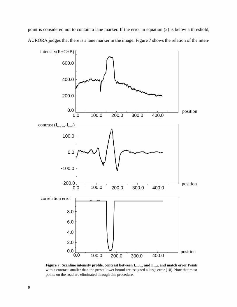
point is considered not to contain a lane marker. If the error in equation (2) is below a threshold,
AURORA judges that there is a lane marker in the image. Figure 7 shows the relation of the inten-
Figure 7: Scanline intensity profile, contrast between Imarker and Iroad, and match error Pointswith a contrast smaller than the preset lower bound are assigned a large error (10). Note that mostpoints on the road are eliminated through this procedure.
0.0 100.0 200.0 300.0 400.0-200.0
-100.0
0.0
100.0
0.0 100.0 200.0 300.0 400.00.0
2.0
4.0
6.0
8.0
0.0 100.0 200.0 300.0 400.00.0
200.0
400.0
600.0
position
position
position
intensity(R+G+B)
contrast (Imarker-Iroad)
correlation error

9
sity profile of a scanline, the contrast between Imarkerand Iroad for each point along this scanline, and
the corresponding binormalized correlation error. Note that the error achieves minimum at the
center of the lane marker where the contrast reaches a maximum.
However, we found that this method still did not always perform satisfactorily because lane mark-
ers in the real world typically do not have clean step edges at both sides. Instead, the edges may be
blurry, which can cause a large correlation error. AURORA overcomes this problem by ignoring
the sections of the scanline around the edges of the lane marker; it only uses the more reliable data
away from the marker edges to adjust the template and compute thebinormalized correlation,as
shown in Figure 8. This technique is similar to that employed by the SCARF road following sys-
tem [2] to detect the boundary between the road and non-road regions on unstructured roads.
Ignoring these regions of the template also makes the algorithm more tolerant to variations in the
width of the lane marker. We were concerned that this procedure might reduce localization accu-
racy, but experiments showed that this accuracy is well preserved.
3.1.2. Local Search Strategy
Since vehicles typically travel at speeds greater than 25m/sec on the highway, it is imperative that
areas which account for large partof absolute correlation error
areas which we ignore duringcorrelation to reduce error
step edge template template with gaps
Figure 8: Comparison of step edge template and the template with gaps

10
AURORA operate in real time. AURORA achieves its 60 Hz cycle rate by processing only a sin-
gle scanline per image. We further improved its efficiency by first searching in the vicinity of last
detected marker position. This also helps to avoid confusion caused by spurious features on the
road. The local search range in AURORA is twice the size of the template’s marker region Rmarker.
If the lane marker is within this local search range, it can be detected with less effort than search-
ing through the entire scanline. If AURORA cannot find a lane marker within the local search
range because it lies outside the local search range or because there is no lane marker in this
image, the system extends the search to the whole scanline.
3.1.3. Camera Calibration
Since AURORA uses a wide angle lens to see a large area next to the vehicle, perspective effects
and lens radial distortion are significant. Because of these effects, the width of a lane marker can
vary significantly depending on its position in the image. Our approach is to first perform a cali-
bration in order to determine the marker width to use at each point along the scanline. Because the
camera pose is different each time we mount it on the car, an efficient procedure is required for re-
calibration.
The calibration procedure for AURORA involves the positioning of calibration marks at known
distance from the vehicle in the camera’s field of view, as shown in Figure 9. Typically these
marks are placed 10cm apart. The user then manually indicates the columns in the image at which
these marks appear. By relating distance between marks on the ground to the number of columns
between them in the image, the system then computes a scale factor to convert centimeters to pix-
els for each column in the image. This scale factor is then used to precompute how wide (in pix-
els) a typical lane marker should appear when centered at each column of the image. The size of
the marker region Rmarker, is then adjusted at run-time according to the position in the scanline cur-

11
rently being searched, to compensate for perspective and lens distortion effects. This calibration is
also vital for vehicle lateral displacement estimation, in order to translate a lane marker position
in pixels into a distance measurement.
3.2. Vehicle Lateral Displacement Estimation
Once AURORA locates the lane marker, the next step is to calculate the vehicle’s lateral position.
The same technique used to compensate the marker width for perspective effect and lens distor-
tion is used to compute the vehicle’s distance from the edge of the lane. Specifically, the approxi-
mate lateral position of the vehicle is determined by comparing the location of the detected lane
marker with the locations of the known calibration marks. Linear interpolation is used to deter-
mine the location of lane markers falling between the positions of two calibration marks. Since
the calibration marks are closely spaced, this linear interpolation does not introduce significant
error, as will be shown in section 5.2. AURORA defines the distance between the center of the
vehicle and the center of the lane as the vehicle lateral position. This can be directly computed
Camera calibration illustration The calibration image
calibration stripe
vehicle mounted camera
Figure 9: Camera calibration: Calibration marks are evenly spaced at known intervals.Marks appear unevenly spaced in the image because of perspective effects and lens distortion.

12
from the distance between the vehicle and the lane marker under the assumption of a fixed lane
width (365 cm) and a known vehicle width (152 cm).
3.3. Roadway Departure Warning
After the lane marker is detected and the vehicle’s lateral position estimated, AURORA must
interact with the driver to prevent roadway departure. Currently, AURORA operates in a passive
mode, warning the driver of the danger of roadway departure when appropriate. AURORA esti-
mates if the danger of departure is sufficiently high, and communicates this danger to the driver.
3.3.1. Warning Criterion
There are several alternative algorithms for triggering a roadway departure warning. In the sim-
plest method, the vehicle’s instantaneous lateral displacement from the road center could be used
as the trigger, whereby a warning would be provided whenever the driver deviates from the lane
center by more than a fixed threshold. However, this approach would lead to frequent false
alarms, since people often drive with a fixed offset from the road center of up to 10 cm [3].
Another approach might be to base the warning on the vehicle’s lateral velocity, so that an alarm
is triggered whenever the vehicle is travelling too quickly across the lane. This algorithm would
also lead to inappropriate alarms, since studies of human driver performance show that people
tend to devote their attention to the steering task only intermittently [4]; the vehicle drifts slowly
from the lane center, and then rapidly moves towards it when the driver makes a correction. These
drawbacks are of serious concern since false alarm rates must be very low in such a warning sys-
tem in order to avoid driver irritation.
A better measure of roadway departure danger is time-to-lane-crossing (TLC) [4]. This is the time
remaining before one of the vehicle’s wheels will cross over one of the lane boundaries, assuming
a fixed steering strategy. In the constant offset case, the vehicle’s lateral velocity is near zero, so

13
TLC will be high and no warning will be triggered. In the case in which the lateral velocity is
large during the driver’s correction maneuver, the vehicle’s movement will be towards the center
of the lane, and hence TLC will still be large. It is only when the vehicle is close to the lane
boundary, and moving in the direction that will take it across that boundary, that a warning is trig-
gered using the TLC algorithm. This is the algorithm currently employed in AURORA.
AURORA bases its computation of TLC only on the vehicle’s lateral displacement and lateral
velocity, since the human driving literature [4] and our own measurements (see Figure 10) indi-
cate that the vehicle’s lateral acceleration is usually small between corrective maneuvers.
AURORA’s technique for computing lateral displacement was described earlier. To compute lat-
eral velocity, AURORA uses the recent history of the vehicle’s lateral positions. Specifically,
AURORA estimates the vehicle’s current lateral velocity by computing how far the lane marker
has moved relative to the vehicle in the last 1/2 second.
3.3.2. Warning Modality
Currently, AURORA uses two modalities for communicating roadway departure danger to the
driver: a visual display and an audible alarm. A warning message appears on an LCD monitor
mounted on the dash in front of the driver whenever TLC is below a pre-set threshold (1.5 sec-
onds). Using a pair of stereo speakers, AURORA also triggers an audible alarm, through the left
speaker when the vehicle is drifting off the left side of the road, or through the right speaker if it is
running off the right side of the road.
4. Alternative Approaches
While AURORA has proven to be an effective means for warning of roadway departure danger,
as will be shown in section 5, it is by no means the only alternative. Systems which monitor the
instantaneous lateral position of the vehicle can be divided into infrastructure-based systems,

14
which require modifications to the existing roadway, and vehicle-based systems which rely on
existing roadway characteristics and in-vehicle processing, like AURORA.
Infrastructure based lateral position detection systems typically exploit ferromagnetic markers
(generally wires or magnets) buried in the pavement [7]. Vehicle sensors detect these ferromag-
netic signals and use their intensity to calculate lateral position. They can achieve lateral position
estimation accuracy on the order of several centimeters. Despite this impressive performance, the
cost of deploying and maintaining the embedded markers on all of the nation’s 4 million miles of
rural roadways would be prohibitively expensive, particularly in northern areas of the country
where the markers would most likely result in increased pothole formation.
Figure 10: Plot of the vehicle’s lateral displacement from the road center over time as the driver driftsfrom one side of the lane to the other.Note the smoothness of AURORA’s lateral displacement estimates.Also note that the vehicle’s trajectory can be characterized as periods of relatively constant velocity lateraldrift, punctuated by abrupt corrective maneuvers. Flat regions indicate that marker has left the field of view.
0.0 5.0 10.0 15.0-100.0
-50.0
0.0
50.0
time (s)
displacement(cm)

15
In-vehicle systems typically use video or infrared sensors to detect the position of the road’s lane
markers. These systems can further be divided into two classes based on where the sensor is
mounted. Downward looking systems like AURORA have the advantage of high efficiency and
simplicity on structured roads, and have the potential to achieve higher positioning accuracy. For-
ward looking systems can make use of more road information, so they are not restricted to roads
with lane markers; however, there is a greater possibility that the image features required for cor-
rect lateral estimation will be occluded by cars or pedestrians.
Aerometrics Inc. has developed a downward-looking system utilizing a scanning infrared laser,
mounted behind the front license plate [8]. The laser scans nearly 180 degrees across the roadway
and detectors within the device sense the intensity of reflected laser light. The concrete or asphalt
reflects little of this laser light back to the detector. However the lane markers reflect laser light in
large quantities because the lane marker paint has retroreflective glass beads embedded within it
to increase visibility at night. This difference in returning laser light is used to locate the lane
markers, and to estimate lateral position. This system can detect vehicle lateral position at a rate
of 200-400 Hz. Tests are currently underway to evaluate the performance of this sensor under
adverse weather conditions, when the lane markers are worn or degraded.
There are several forward looking, vision-based roadway departure system currently under inves-
tigation. ALVINN (Autonomous Land Vehicle In A Neural Network) uses a neural network to
learn correct behavior from training data [9]. Like human drivers, ALVINN relies on additional
cues as to the road position, such as road edges or the ruts left by previous vehicles on a snowy
roadway to cope with situations where the lane markings are degraded, obscured, or missing.
The SCARF [2] system classifies individual pixels in the image as road or non-road based on their

16
color, and then uses a Hough transform to find the most probable road position, assuming the road
appears as a trapezoid in the image. It then back-projects the road trapezoid onto the ground plane
and steers to keep the vehicle centered on this region and heading in the direction of the region’s
major axis. Because it only looks for trapezoidal region of road pixels, SCARF can not be used in
situations like multi-lane driving and obstacle avoidance.
VaMoRs [5] used local edge detectors to find the position of highway lane markers in various sub-
regions of the image. A sophisticated control algorithm was employed to keep the vehicle in its
lane. Because of its local feature detectors and parallel implementation, it was capable of process-
ing images at 13 Hz and driving at up to 60 m.p.h. In assuming that important features would have
strong edges associated with them in the image, it was not able to handle older highways with
faded lane markers, cracked pavement, or heavily-shadowed stretches of road where important
edges are often obscured.
5. Experimental Results
Together, the vision-based lateral position estimator, the TLC algorithm and the dual modality
driver interface comprise the AURORA roadway departure warning system. We have performed
numerous off-line tests using videotapes of roads, and several on-vehicle runs to characterize the
performance of these components and the system as a whole. The results of these experiments are
discussed in this section.
5.1. Vision-Based Lane Marker Tracking Performance
Tests of the lane marker tracking algorithm have been conducted on a variety of road types under
several different weather conditions. The road types the algorithm has been tested on: two lane
rural roads, city streets, and divided interstate highway. Weather during the tests has included

17
sunny, overcast, and rainy conditions. Most experiments were carried out during the day, but dusk
and night operation has been verified by illuminating the roadway using a lamp mounted on the
side of the vehicle next to the camera.
The system has demonstrated good performance tracking lane markers. Quantitatively, on roads
with dashed white lane markers, the system misses, on average, about 1 in every 100 lane mark-
ers, usually when the marker is severely faded or obscured. This type of mistake normally occurs
on a single lane marker, and does not propagate to subsequent markers since the system only
relies on the current image for its processing. Figure 11 is the display on the monitor once
AURORA has detected a white lane marker.
While we have been using white lane markers in the previous examples, AURORA in fact works
equally well for double yellow lane marker. The only differences in the algorithm are that
AURORA uses color information rather than simple intensity in the template, and the template
has a different shape, as is shown in Figure 12. Instead of using the summation of red (R), green
(G) and blue (B) pixel values as intensity for each pixel, AURORA uses R+G-2B as a simple
Figure 11: Display on the monitor once a lane marker is detected
real lane markerintensity profile
adjustable template
position of thelane marker

18
means of highlighting pixels with a yellow hue in the image. A typical result of detecting double
yellow lane marker is shown in Figure 13. In many miles of tests on yellow lined roads,
AURORA has not yet lost track of a continuous yellow lane marker.
5.2. Vehicle Lateral Displacement Estimation
We evaluate the vehicle lateral displacement estimation by comparing the result given by the sys-
tem and our manual measurement. Table 1 shows the comparison in centimeters of 14 randomly
marker width
road color value
marker color value
Figure 12: template for double yellow lane markerpixels
yello
w h
ue v
alue
Figure 13: Display on the monitor once a double lane marker is detected

19
selected lane markers lying at different positions on the road. The average absolute error is 0.8
cm. The standard deviation of the error in position estimation is 1.05cm.
5.3. Roadway Departure Warning
Figure 14 shows AURORA’s estimate of TLC in the one second interval preceding a lane cross-
ing. Note that as the time until lane crossing decreases, so does AURORA’s estimate of the time
remaining. The average error in AURORA’s estimate of TLC is 0.2 seconds. The standard devia-
tion is 0.23 seconds. Our threshold to trigger the alarm is 1.5 seconds. Initial tests show that this
threshold is appropriate and acceptable to the driver. This 1.5 second TLC threshold minimizes
the number of false alarms due to normal deviation within the lane, while still providing a warn-
ing early enough for the driver to respond before lane departure.
Table 1: Comparison of vehicle lateral displacement between Aurora system and manual measurement
Samples 1 2 3 4 5 6 7 8 9 10 11 12 13 14
Aurora 142.6 130.5 120.9 117.5 114.1 100.4 94.2 78.0 62.7 52.1 47.7 38.5 34.4 28.4
Manual 143.1 132.1 122.4 120.0 112.9 100.8 94.2 77.0 62.6 52.4 47.4 37.4 34.1 27.7
Error -0.5 -1.6 -1.5 -2.5 1.2 -0.4 0.0 1.0 0.1 -0.3 0.3 1.1 0.3 0.7
Figure 14: AURORA’s estimate of TLC in the one second interval preceding a lane crossing
0.0 0.2 0.4 0.6 0.80.0
0.5
1.0
time (s)
TLC (s)
Actual TLC
Estimated TLC

20
6. Discussion
AURORA is a vision-based roadway departure warning system. It employs a simple downward
looking vision system consisting of a color camera with a wide angle lens, a digitizer, and a Sun
Sparc portable workstation. By applying a straightforwardbinormalized adjustable template cor-
relation method, it is able to reliably track lane markers on the road at 60 Hz. Atime-to-lane-
crossing (TLC) measurement is calculated for each image field based on the accurate estimation
of the vehicle’s lateral displacement, triggering a warning alarm when the TLC falls below a pre-
set threshold. Experiments have been done on several different road, weather and lighting condi-
tions with excellent results.
Though the result is promising, experiments seeking to better quantify the system’s performance
under a broad range of road types and environmental conditions still need to be carried out. We
are also investigating techniques to prevent false alarms which can occur during lane change
maneuvers. These techniques could be as simple as monitoring the turn indicator, or as sophisti-
cated as reasoning about the vehicle’s current lane and the driver’s intentions.
Additional human factors experiments are also required to refine the system. We will continue our
road tests of AURORA to further refine important parameters such as the TLC warning threshold.
We will also conduct tests using the University of Iowa driving simulator to recreate conditions
too rare or dangerous for live experiments.
One potential problem with a roadway departure countermeasure like AURORA is that simply
warning the driver may not be sufficient. In a large fraction of roadway departure crashes, the
driver is unable to react quickly because he/she has fallen asleep or is intoxicated. In these situa-
tions, an active steering and/or speed control may be required to prevent a collision. An initial

21
step in this direction would be to apply torque to the steering wheel in the appropriate direction.
The torque could be smaller than is required to actually correct the vehicle’s trajectory, since it
would be intended mainly to alert the driver to the danger and to help him/her begin the corrective
maneuver.
A more ambitious extension of AURORA we are pursuing is to combine it with a satellite-based
position estimation system and a digital map of the road network to allow AURORA to estimate
the curvature of the road ahead. By combining this forward preview capability with AURORA’s
local estimate of lateral position, it should be possible to calculate a steering direction that will
keep the vehicle centered in its lane. This advanced AURORA system could form a highly reli-
able, fully automated lateral control system.
As for the alternative approaches, we are currently conducting experiments with several of them
(ALVINN and the Aerometrics system) to evaluate their sensing performance, and to compare
their effectiveness as warning systems.
ACKNOWLEDGMENT
This work is funded by the National Highway Traffic Safety Administration (NHTSA) under con-
tract no. DTNH22-93-c-07023. Thanks to Shumeet Baluja, John Hancock, Conrad Poelman, Peter
Rander, and James Rehg for offering their generous help and precious comments.
REFERENCES
[1] P. Fancher, et. al, “Potential Safety Applications of Advanced Technology”, U.S. Department
of Transportation, Federal Highway Administration, Publication No. FHWA-RD-93-080, January

22
1994
[2] Crisman, J.D. and Thorpe C. (1990) Color vision for Road Following, Vision and Navigation:
The CMU Navlab C. Thorpe (Ed), Kluwer Academic Publishers, Boston.
[3] Blaauw, G.J. (1982) Driving experience and task demands in simulator and instrumented car:
A validation study, Human Factors, Vol.24, pp. 473-486.
[4] Godthelp, H. et. al. (1984) The development of a time-related measure to describe driving
strategy. Human Factors, Vol.26, pp.257-268.
[5] Dichmanns, E.D. and Zapp, A. (1987) Autonomous high speed road vehicle guidance by com-
puter vision. Proceedings of the 10th World Congress on Automatic Control, Vol. 4, Munich,
West Germany.
[6] Kluge, K. and Thorpe, C. (1990) Explicit models for robot road following. Vision and Naviga-
tion: The CMU Navlab C. Thorpe (Ed.), Kluwer Academic Publishers, Boston.
[7] Schladover, S.E. et al, Automatic Vehicle Control Developments in the PATH Program, IEEE
Transactions on Vehicular Technology, Vol. 40, Feb. 1991.
[8] Carlos Schuler, Personal Communications, Feb. 1994.
[9] Pomerleau, D. (1993) Neural Network Perception for Mobile Robot Guidance, Kluwer Aca-
demic Publishing.