Embed Size (px)
Citation preview
Aura Professional Advanced Flight Control SystemFPZAURA08PRO FPZAURA12PRO | User Guide
SPECIAL LANGUAGE DEFINITIONS
The following terms are used throughout the product literature to indicate various levels of potential harm when operating this product:
Procedures, which if not properly followed, create a possibility of physical property damage AND a little or no possibility of injury.
Procedures, which if not properly followed, create the probability of physical property damage AND a possibility of serious injury.
Procedures, which if not properly followed, create the probability of property damage, collateral damage, and serious injury OR create a high probability of serious injury.
NOTICE:
CAUTION:
WARNING:ATTENTION
Read the ENTIRE instruction manual to become familiar with the features of this product before operating. Failure to assemble or operate the product correctly can result in damage to the product, personal property, and cause serious or fatal injury.
For advanced topics, there is a more in-depth manual available online.
Please visit wiki.�exinnovations.com/aura to view the Expanded Online User Guide.
The Aura Con�g Tool is required for programming the Aura Professional and found at the location shown above.
WARNING
This product is not intended for use by children under 14 years without direct adult supervision.
This product is only intended for use with unmanned, hobby-grade, remote-controlled aircraft. Flex Innovations will not provide warranty service for damage related to, nor will it claim liability for any use of this product outside of the scope of its intended use.
WARNING! !
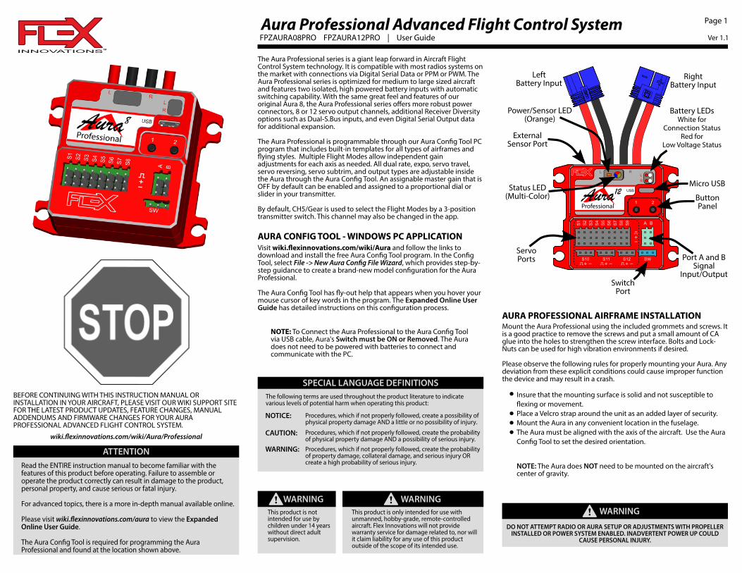
The Aura Professional series is a giant leap forward in Aircraft Flight Control System technology. It is compatible with most radios systems on the market with connections via Digital Serial Data or PPM or PWM. The Aura Professional series is optimized for medium to large sized aircraft and features two isolated, high powered battery inputs with automatic switching capability. With the same great feel and features of our original Aura 8, the Aura Professional series offers more robust power connectors, 8 or 12 servo output channels, additional Receiver Diversity options such as Dual-S.Bus inputs, and even Digital Serial Output data for additional expansion.
The Aura Professional is programmable through our Aura Con�g Tool PC program that includes built-in templates for all types of airframes and �ying styles. Multiple Flight Modes allow independent gain adjustments for each axis as needed. All dual rate, expo, servo travel, servo reversing, servo subtrim, and output types are adjustable inside the Aura through the Aura Con�g Tool. An assignable master gain that is OFF by default can be enabled and assigned to a proportional dial or slider in your transmitter.
By default, CH5/Gear is used to select the Flight Modes by a 3-positiontransmitter switch. This channel may also be changed in the app.
DO NOT ATTEMPT RADIO OR AURA SETUP OR ADJUSTMENTS WITH PROPELLER INSTALLED OR POWER SYSTEM ENABLED. INADVERTENT POWER UP COULD
CAUSE PERSONAL INJURY.
WARNING!
SW
S1
S6
S2
S3
S5
S8
S7
S4
1 2
S9
S11 S12
BA
S10
12
Power/Sensor LED(Orange)
Status LED(Multi-Color)
Battery LEDsWhite for
Connection StatusRed for
Low Voltage Status
ButtonPanel
Port A and BSignal
Input/OutputSwitch
Port
ServoPorts
Micro USB
ExternalSensor Port
LeftBattery Input
RightBattery Input
Ver 1.1
Page 1
AURA CONFIG TOOL - WINDOWS PC APPLICATIONVisit wiki.�exinnovations.com/wiki/Aura and follow the links to download and install the free Aura Con�g Tool program. In the Con�g Tool, select File -> New Aura Con�g File Wizard, which provides step-by-step guidance to create a brand-new model con�guration for the Aura Professional.
The Aura Con�g Tool has �y-out help that appears when you hover your mouse cursor of key words in the program. The Expanded Online User Guide has detailed instructions on this con�guration process.
AURA PROFESSIONAL AIRFRAME INSTALLATIONMount the Aura Professional using the included grommets and screws. It is a good practice to remove the screws and put a small amount of CA glue into the holes to strengthen the screw interface. Bolts and Lock-Nuts can be used for high vibration environments if desired.
Please observe the following rules for properly mounting your Aura. Any deviation from these explicit conditions could cause improper function the device and may result in a crash.
Insure that the mounting surface is solid and not susceptible to �exing or movement.Place a Velcro strap around the unit as an added layer of security.Mount the Aura in any convenient location in the fuselage.The Aura must be aligned with the axis of the aircraft. Use the Aura Con�g Tool to set the desired orientation.
BEFORE CONTINUING WITH THIS INSTRUCTION MANUAL OR INSTALLATION IN YOUR AIRCRAFT, PLEASE VISIT OUR WIKI SUPPORT SITE FOR THE LATEST PRODUCT UPDATES, FEATURE CHANGES, MANUAL ADDENDUMS AND FIRMWARE CHANGES FOR YOUR AURA PROFESSIONAL ADVANCED FLIGHT CONTROL SYSTEM.
wiki.�exinnovations.com/wiki/Aura/Professional
NOTE: The Aura does NOT need to be mounted on the aircraft's center of gravity.
NOTE: To Connect the Aura Professional to the Aura Con�g Tool via USB cable, Aura's Switch must be ON or Removed. The Aura does not need to be powered with batteries to connect and communicate with the PC.

CONNECTING A RECEIVERThe Aura Professional supports several connection methods. Supported signal formats include Serial Data (S.Bus, SRXL, etc), PPM stream, and PWM. In the case of Futaba S.Bus, it can accept up to two inputs allowing further receiver antenna diversity. See the diagrams that follow for examples of receiver connections.
The full range of options (including dual serial input and serial output) can be found in the expanded online user guide. The Aura Con�g Tool will let you select your speci�c choice.
Exercise extreme caution when plugging in any lead that could potentially supply power, or short power buses. It is possible to 'reverse' or 'short' a power connection by even partially plugging in a connector. Examples (but not limited to):
WARNING!
Connecting multiple batteries or power leads. Use switches, extensions, and Y harnesses with extreme care.Connecting PWM Cables. Install PWM cables with power removed from the system. Inspect carefully before powering the system.
THE USER MUST PROVIDE AURA WITH A STABLE AND RELIABLE POWER SUPPLY. FAILURE TO DO SO COULD RESULT IN LOSS OF CONTROL OR CRASH.
Digital Serial Data or PPM Connection
CH
7C
H6
Ch
5R
UD
DELE
VA
ILET
HR
OS
ER
IAL / P
PM
RX
To ESCor Throttle
Servo
SW
S1 S6S2 S3 S5 S8S7S4
1 2
S9
S11 S12
BA
S10
12
Supported Serial Formats Spektrum SRXL Futaba or FrSky or Hitec S.BUS Jeti UDI Graupner SUMD JR DMSS Mode B
PPM also Supported
Insert one end of the included male to male extension into Port A or Port B on the Aura (Port A shown here). Connect the other end to your receiver’s data port.
Refer to your radio manufacturer’s instructions for speci�c information regarding con�guring your system’s Digital Serial Data (or PPM) communication settings for use with third party applications and hardware.
PWM (Servo Port) Connections
CH
7C
H6
Ch
5R
UD
DE
LEV
AILE
TH
RO
RX
To ESCor Throttle
Servo
SW
S1 S6S2 S3 S5 S8S7S4
1 2
S9
S11 S12
BA
S10
12
RECEIVER OUTAileron
RudderCH5/Gear
Elevator
S4
S3S2S1
AURA IN
ESC/THROTTLE WILL CONNECT TO THE RECEIVER DIRECTLY.
NOTE
For PWM Connections you must use the Aura Con�g tool's "New Aura Con�g File Wizard" to specify radio system type and PWM input method.
NOTE
Use 4 male to male cables to connect the receiver to the Aura. All expected (typically 4) PWM input connections must be properly made before you will get control of the model (typically 4).
Control Mode A: Manual Control (Gyro Off)Control Mode B: Low Gyro GainsControl Mode C: Medium Gyro GainsControl Mode D: High Gyro Gains
Each Control Mode has speci�c gyro settings (such as gain, stick priority and more) and each Control Mode can be assigned to one or more �ight modes depending on user preference. Aura defaults are listed below.
CONTROL MODES
ATTENTION
The Aura Professional draws a small amount of electrical power even when switched OFF. Un-Plug the batteries when not in use for more than several hours.The receiver(s) will receive power from the Aura Professional via the A and/or B Port (or servo ports when using PWM) when the Aura power is ON. Be very careful to make sure the polarity of all connectors is correct.Do not use any type of BEC (Battery Eliminator Circuit) with the Aura Professionals. If a chosen ESC includes a BEC, disable it by removing the "+" pin from the connector and taping it back. Connect only the "-" and signal pins to the Aura. Power the Aura through the dual input power leads.
Page 2
TRANSMITTER SETUP
The Aura Professional defaults to 3 Flight Modes that are changed by your transmitter's Channel 5 (Gear). Assign Channel 5 (Gear) to a 3-position switch of your choice. For best results, start with a freshly reset (blank) transmitter model and make the changes per the chart below.Aura expects an aircraft type of 1 aileron, 1 elevator and 1 rudder from the transmitter. For more advanced models (such as those with �aps), see the Expanded Online User Guide in the Aura Wiki.
TRANSMITTER CONFIGURATION GUIDE
ATV Setup
Sub TrimTrim LeversCH5 (Gear)Reversing All channels normal
Assigned to a 3-position switchVeri�ed neutral
Veri�ed neutral, not allowed
Throttle, CH5/Gear
Aileron,Elevator,Rudder 125%*
100%**JR XBus Mode B users should set the throttle, aileron, elevator, rudder, and gear values to 88%
NOTE
FLIGHT MODESFlight Modes are an integral feature of the Aura. Each Flight Mode is assigned a speci�c set of dual rates, exponential values, and one or more Control Modes to suit a speci�c �ying style or preference.
Flight Modes can be changed at any time during �ight. Typically, the Flight Mode switch is assigned to the Channel 5/Gear channel on a 3-position switch (a 2-position switch may be used but the Aura will be limited to two (2) Flight Modes).
A common Flight Mode setup would be:
Flight Mode 1: Low Rates with Gyro OffFlight Mode 2: Low Rates with Low Gyro GainsFlight Mode 3: High Rates with High Gyro Gains
POWERING AURA PROFESSIONAL
Power your Aura 8 or 12 Professional by plugging two 5V to 9V DC power sources into the EC3 battery input connectors. Identical 7.4V Li-Po or 6.6V LiFe batteries are recommended. Make sure all of your servos and devices are capable of handling the voltage of your chosen power source.
The provided switch may optionally be installed in the "SW" port. Any switch that connects the "SW" port signal pin and ground pin can be used. With the switch removed, the unit will be switched ON
White LEDs in the upper right window indicate when the battery is providing power to the Aura. If one power source has a lower voltage than the other, the White LED will remain off until the batteries come into balance. The Red LEDs indicate when the batteries are below the programmable low voltage thresholds.
The Aura Professional in not a receiver. Any Binding is done solely between the Receiver and the Transmitter.
Choose a receiver that is appropriate for your models size and type. Consult your radio manufacturer if you need assistance. Follow the instructions provided with your radio components and bind the receiver to your transmitter prior to con�guring to the Aura Professional. Test your receiver function with a servo plugged into a receiver port.
BIND YOUR RECEIVER

TRANSMITTER COMMAND TEST
Refer to the chart below to determine the proper control surface directions when moving your transmitter sticks. If controls are reversed, change the Servo Direction under the Servo Ports tab using the Aura Con�g Tool. DO NOT REVERSE CONTROLS IN THE TRANSMITTER.
Note that BOTH the Transmitter Control Direction Test AND the Flight Controller Sensor Direction Test MUST BOTH BE PASSED!IF ONE DOES NOT PASS, DO NOT FLY!
The Aura outputs activate with a valid receiver signal. Perform these tests in the Flight Mode with the highest gain for best visibility. Repeat these tests in all gyro-enabled Flight Modes.
Control surface de�ections are exaggerated in the drawings below for clarity. Please note that the control surfaces will move ONLY while the aircraft is ROTATING.
Perform a test of the gyro system to verify the corrections made for a given movement are correct. If any of the tests do not result in the correct reaction for the airplane's gyro system, DO NOT FLY THE AIRPLANE, and contact us by email at support@�exinnovations.com or by phone at (866) 310-3539.
REPLACEMENT AND OPTION PARTS LISTING
FPZAURA08PRO Aura 8 Professional Flight Control SystemFPZAURA12PRO Aura 12 Professional Flight Control SystemFPZAU01 3pc Male to Male Servo/ Serial Bus CableFPZAU02 Micro USB CableFPZAU03 Aura Professional Remote SensorFPZAU04 Aura Professional Power SwitchFPZAU05 Aura Professional Screw and Grommet Set
SENSOR TESTPage 3
Perform a failsafe check before first flight and after making changes to your transmitter or the connection between your receiver and Aura.
Make your power plant inoperable. Make sure Fuel powered engines are OFF. Remove the propeller from electric models.
WARNING!
If you are using a PWM receiver, during a failsafe event, if the input pulses are lost, the Aura will set the its ports will hold last position and you will see a Blue LED in the Aura’s status window. The throttle is driven by your receiverIf you used a PPM receiver, during a failsafe event, if the input pulses are lost, the Aura will set the throttle to the throttle value learned in the bind process. other channels will hold last position and you will see a Blue LED in the Aura’s status window.If you use a serial linked receiver Aura will use any failsafe values that you have setup between your transmitter and receiver (In some cases, the Green Aura LED may remain on as Aura is getting valid failsafe positions from the receiver).
FAILSAFE AND CHECKS
Remember, in all cases, if your receiver has a working throttle port, USE IT. Your throttle servo will be driven directly from your radio transmitter/receiver.
Warning: Some Spektrum SRXL receivers do NOT send a proper failsafe throttle position out in their SRXL serial data. Use the Spektrum receiver's throttle port.

LIMITED WARRANTYWarranty Coverage - Flex Innovations, Inc. and its authorized resellers (“Flex”) warrant to the original purchaser that the product purchased (the “Product”) it will be free from defects in materials and workmanship at the date of purchase.
Outside of Coverage - This warranty is not transferable and does not cover: (i) Products with more than 45 days after purchased date; (ii) Damage due to acts of God, accident, misuse, abuse, negligence, commercial use, or due to improper use, installation, operation or maintenance; (iii) Modication of or to any part of the Product; (iv) Product not compliant with applicable technical regulations; (v) Shipping damage; (vi) Cosmetic damage.
OTHER THAN THE EXPRESS WARRANTY ABOVE, FLEX MAKES NO OTHER WARRANTY OR REPRESENTATION, AND HEREBY DISCLAIMS ANY AND ALL IMPLIED WARRANTIES, INCLUDING, WITHOUT LIMITATION, THE IMPLIED WARRANTIES OF NONINFRINGEMENT, MERCHANTABILITY AND FITNESS FOR A PARTICULAR PURPOSE. THE PURCHASER ACKNOWLEDGES THAT THEY ALONE HAVE DETERMINED THAT THE PRODUCT WILL SUITABLY MEET THE REQUIREMENTS OF THE PURCHASER’S INTENDED USE.
Purchaser’s Solution - Flex’s sole obligation and purchaser’s sole and exclusive remedy shall be that Flex will, at its option, either (i) service, or (ii) replace, any Product determined by Flex to be defective. Flex reserves the right to inspect any and all Product(s) involved in a warranty claim. Service or replacement decisions are at the sole discretion of Flex. Proof of purchase is required for all warranty claims. SERVICE OR REPLACEMENT AS PROVIDED UNDER THIS WARRANTY IS THE PURCHASER’S SOLE AND EXCLUSIVE REMEDY.
Limitation of Liability - FLEX SHALL NOT BE LIABLE FOR SPECIAL, INDIRECT, INCIDENTAL OR CONSEQUENTIAL DAMAGES, LOSS OF PROFITS OR PRODUCTION OR COMMERCIAL LOSS IN ANY WAY, REGARDLESS OF WHETHER SUCH CLAIM IS BASED IN CONTRACT, WARRANTY, TORT, NEGLIGENCE, STRICT LIABILITY OR ANY OTHER THEORY OF LIABILITY, EVEN IF FLEX HAS BEEN ADVISED OF THE POSSIBILITY OF SUCH DAMAGES.
Further, in no event shall the liability of Flex exceed the individual price of the Product on which liability is asserted. As Flex has no control over use, setup, assembly, modi�cation or misuse, no liability shall be assumed nor accepted for any resulting damage or injury. By the act of use, setup or assembly, the user accepts all resulting liability. If you as the purchaser or user are not prepared to accept the liability associated with the use of the Product, purchaser is advised to return the Product immediately in new and unused condition to the place of purchase.
Law - These terms are governed by Florida law (without regard to con�ict of law principals). This warranty gives you speci�c legal rights, and you may also have other rights which vary from state to state. FLEX RESERVES THE RIGHT TO MODIFY THIS WARRANTY AT ANY TIME WITHOUT PRIOR NOTICE.
Questions Assistance - For customer support in your region, visit:http://www.�exinnovations.com/articles.asp?ID=269Inspection or Services - If this Product needs to be inspected or serviced and is compliant in the region you live and use the Product in, please contact your regional Flex authorized reseller. Pack the Product securely using a shipping carton. Please note that original boxes needs to be included, but are not designed to withstand the rigors of shipping without additional protection. Ship via a carrier that provides tracking and insurance for lost or damaged parcels, as Flex is not responsible for merchandise until it arrives and is accepted at our facility.
Warranty Requirements - For Warranty consideration, you must include your original sales receipt verifying the proof of purchase date. Provided warranty conditions have been met, your Product will be replaced free of charge. Shipping charges are as follow: to Flex by customer, Flex out it is by Flex. Service or replacement decisions are at the sole discretion of Flex.
Instructions for disposal of WEEE by users in the European Union This product must not be disposed of with other waste. Instead, it is the user's responsibility to dispose of their waste equipment by handing it over to a designated collections point for the recycling of waste and electronic equipment. The seperate collection and recycling of your waste equipment at the time of disposal will help to conserve natural resources and ensure that it is recycled in a manner that protects human health and the environment. For more information about where to drop off your waste equipment for recycling, please contact your local city office, your household waste disposal service or where you purchased this product.
COMPLIANCE INFORMATION FOR THE EUROPEAN UNION
Declaration of Conformity (In accordance with ISO/IEC 17050-1)
Product(s): Item Number(s):
Aura 8 ProfessionalAura 12 ProfessionalFPZAURA08PROFPZAURA12PRO
The object of declaration described above is in conformity with the requirements of the speci�cations listed below, following the provisions of the EMC Directive 2004/108/EC.
EN 55024EN 55022
EN 61000-4-3EN 55022/CISPR 22
Page 4
© 2019 Flex Innovations, llc.Premier Aircraft™, Potenza™, and Top Value RC™ are trademarks
or registered trademarks of Flex Innovations, llc.DSM®, and DSMX™ are trademarks of Horizon Hobby, llc.
Futaba is a registered trademark of Futaba Denshi Kogyo Kabushiki Kaisha Corporation of Japan.
Jeti™, UDI, and Jeti Model are trademarks or registered trademarks of Jelen, Ing. Stanislav of Czech Republic
Hitec is a trademark or registered trademark of Hitec RCD USA Inc.HoTT is a registered trademark of SJ, Inc.
For information on �ying responsibly, please visit this site:http://knowbeforeyou�y.org/