Embed Size (px)
Citation preview
Product Data Sheet00813-0100-4702, Rev KC
August 2018
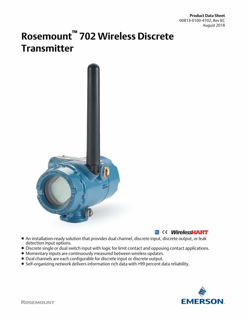
Rosemount™ 702 Wireless DiscreteTransmitter
■ An installation-ready solution that provides dual channel, discrete input, discrete output, or leakdetection input options.
■ Discrete single or dual switch input with logic for limit contact and opposing contact applications.■ Momentary inputs are continuously measured between wireless updates.■ Dual channels are each configurable for discrete input or discrete output.■ Self-organizing network delivers information rich data with >99 percent data reliability.
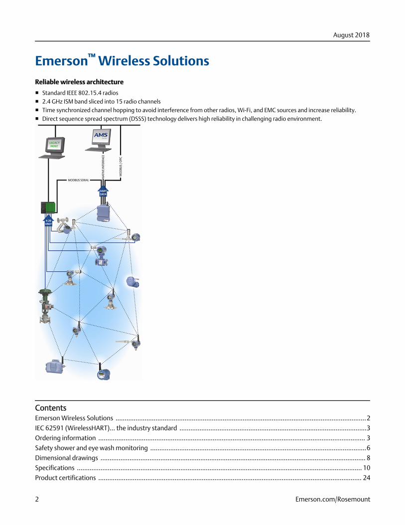
Emerson™ Wireless SolutionsReliable wireless architecture
■ Standard IEEE 802.15.4 radios■ 2.4 GHz ISM band sliced into 15 radio channels■ Time synchronized channel hopping to avoid interference from other radios, Wi-Fi, and EMC sources and increase reliability.■ Direct sequence spread spectrum (DSSS) technology delivers high reliability in challenging radio environment.
ContentsEmerson Wireless Solutions ..........................................................................................................................................2
IEC 62591 (WirelessHART)... the industry standard .......................................................................................................3
Ordering information ................................................................................................................................................... 3
Safety shower and eye wash monitoring .......................................................................................................................6
Dimensional drawings .................................................................................................................................................. 8
Specifications ............................................................................................................................................................. 10
Product certifications ................................................................................................................................................. 24
August 2018
2 Emerson.com/Rosemount
SmartPower™ solutions
■ Optimized Emerson instrumentation, both hardware and software, to extend power module life■ Intrinsically safe power module allows field replacements without removing the transmitter from the process, keeping personnel
safe, and reducing maintenance costs.
IEC 62591 (WirelessHART®)... the industry standardSelf-organizing, adaptive mesh routing
■ No wireless expertise required, network automatically finds the best communication paths.■ The self-organizing, self-healing network manages multiple communication paths for any given device. If an obstruction is
introduced into the network, data will continue to flow because the device already has other established paths. The network willthen lay in more communication paths as needed for that device.
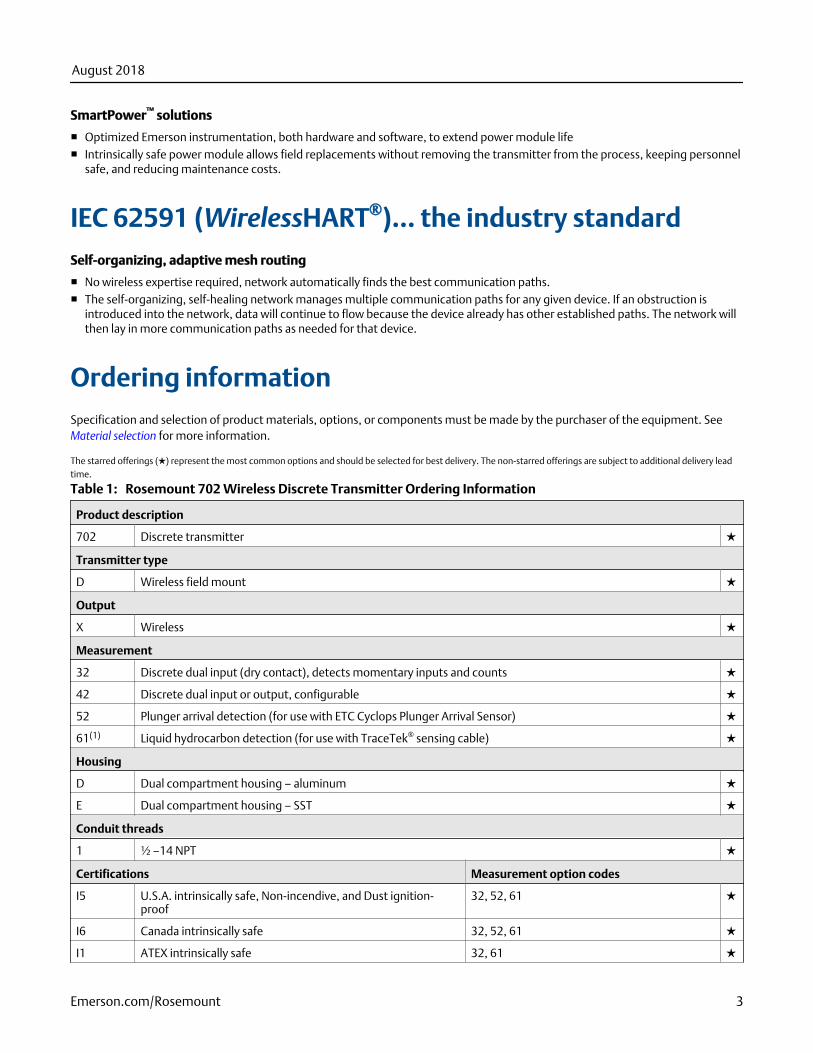
Ordering informationSpecification and selection of product materials, options, or components must be made by the purchaser of the equipment. See Material selection for more information.
The starred offerings (★) represent the most common options and should be selected for best delivery. The non-starred offerings are subject to additional delivery leadtime.
Rosemount 702 Wireless Discrete Transmitter Ordering InformationTable 1:
Product description
702 Discrete transmitter ★
Transmitter type
D Wireless field mount ★
Output
X Wireless ★
Measurement
32 Discrete dual input (dry contact), detects momentary inputs and counts ★
42 Discrete dual input or output, configurable ★
52 Plunger arrival detection (for use with ETC Cyclops Plunger Arrival Sensor) ★
61(1) Liquid hydrocarbon detection (for use with TraceTek® sensing cable) ★
Housing
D Dual compartment housing – aluminum ★
E Dual compartment housing – SST ★
Conduit threads
1 ½ –14 NPT ★
Certifications Measurement option codes
I5 U.S.A. intrinsically safe, Non-incendive, and Dust ignition-proof
32, 52, 61 ★
I6 Canada intrinsically safe 32, 52, 61 ★
I1 ATEX intrinsically safe 32, 61 ★
August 2018
Emerson.com/Rosemount 3
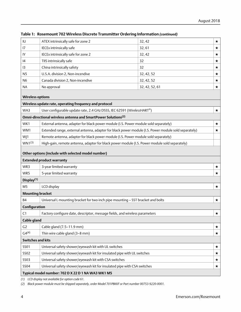
Rosemount 702 Wireless Discrete Transmitter Ordering Information (continued)Table 1:
IU ATEX intrinsically safe for zone 2 32, 42 ★
I7 IECEx intrinsically safe 32, 61 ★
IY IECEx intrinsically safe for zone 2 32, 42 ★
I4 TIIS intrinsically safe 32 ★
I3 China intrinsically safety 32 ★
N5 U.S.A. division 2, Non-incendive 32, 42, 52 ★
N6 Canada division 2, Non-incendive 32, 42, 52 ★
NA No approval 32, 42, 52, 61 ★
Wireless options
Wireless update rate, operating frequency and protocol
WA3 User configurable update rate, 2.4 GHz DSSS, IEC 62591 (WirelessHART®) ★
Omni-directional wireless antenna and SmartPower Solutions(2)
WK1 External antenna, adapter for black power module (I.S. Power module sold separately) ★
WM1 Extended range, external antenna, adapter for black power module (I.S. Power module sold separately) ★
WJ1 Remote antenna, adapter for black power module (I.S. Power module sold separately)
WN1(3) High-gain, remote antenna, adapter for black power module (I.S. Power module sold separately)
Other options (include with selected model number)
Extended product warranty
WR3 3-year limited warranty ★
WR5 5-year limited warranty ★
Display(1)
M5 LCD display ★
Mounting bracket
B4 Universal L mounting bracket for two inch pipe mounting – SST bracket and bolts ★
Configuration
C1 Factory configure date, descriptor, message fields, and wireless parameters ★
Cable gland
G2 Cable gland (7.5–11.9 mm) ★
G4(4) Thin wire cable gland (3–8 mm) ★
Switches and kits
SS01 Universal safety shower/eyewash kit with UL switches ★
SS02 Universal safety shower/eyewash kit for insulated pipe with UL switches ★
SS03 Universal safety shower/eyewash kit with CSA switches ★
SS04 Universal safety shower/eyewash kit for insulated pipe with CSA switches ★
Typical model number: 702 D X 22 D 1 NA WA3 WK1 M5
(1) LCD display not available for option code 61.
(2) Black power module must be shipped separately, order Model 701PBKKF or Part number 00753-9220-0001.
August 2018
4 Emerson.com/Rosemount
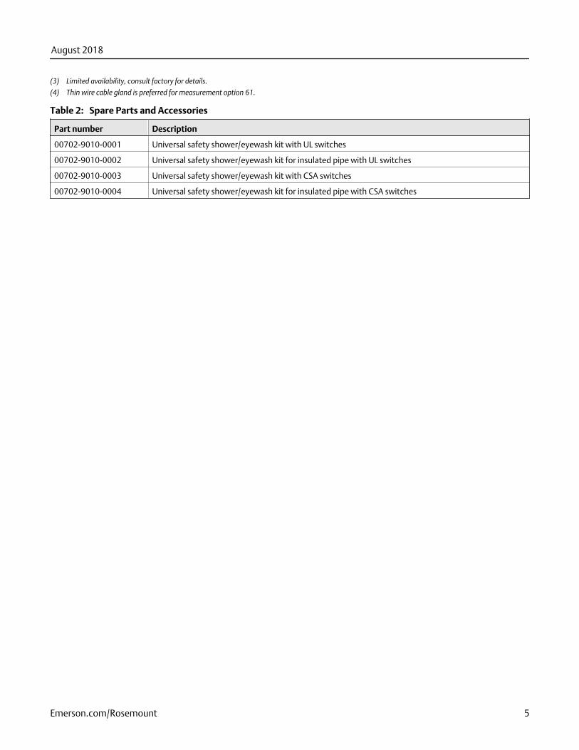
(3) Limited availability, consult factory for details.
(4) Thin wire cable gland is preferred for measurement option 61.
Spare Parts and AccessoriesTable 2:
Part number Description
00702-9010-0001 Universal safety shower/eyewash kit with UL switches
00702-9010-0002 Universal safety shower/eyewash kit for insulated pipe with UL switches
00702-9010-0003 Universal safety shower/eyewash kit with CSA switches
00702-9010-0004 Universal safety shower/eyewash kit for insulated pipe with CSA switches
August 2018
Emerson.com/Rosemount 5
Safety shower and eye wash monitoringThe Rosemount 702 Transmitter can be used to monitor safety showers and eye wash stations by using switch kits provided byTopWorx
™, an Emerson company. These kits are ordered as a part of the Rosemount 702 model code and are available for both
insulated and un-insulated pipes. These kits contain the switches, brackets and cables that are necessary to install the transmitter tomonitor both the safety shower and the eye wash in a single station. Because each has two input channels, one transmitter can beused to monitor both a safety shower and an eye wash.
Each safety shower monitoring kit contains:
■ Two TopWorx GO™ Switch magnetic proximity switches■ Two cables, six-foot and 12-foot■ Two black polymer cable glands■ Mounting kit for safety shower and eye wash
UL and CSA switches
Safety shower and eye wash monitoring kits are available with either UL or CSA switches. This designation refers to the ordinarylocation certification of the GO Switch in the kit. These are not hazardous locations certificates. The Go Switch is regarded as asimple apparatus and does not require its own hazardous locations certificate. Either GO Switch is suitable for installation inhazardous locations when wired to the Rosemount 702 with an appropriate hazardous locations certificate. The CSA GO Switch isfor applications in Canada, the UL GO Switch is for applications in all other world areas.
Installation drawings and instructions
Installation drawings and instructions for safety shower and eye wash kits are included in the Rosemount 702 Transmitter Reference Manual. This manual can be downloaded at the Rosemount 702 Transmitter Product Page.
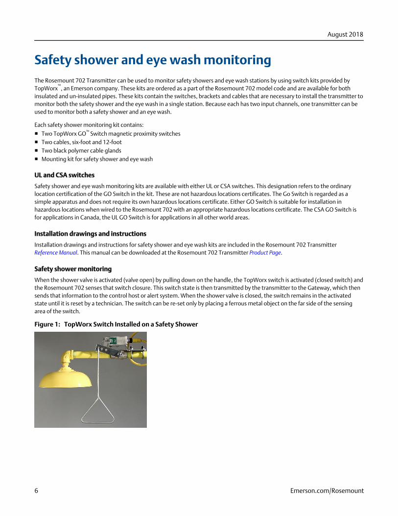
Safety shower monitoring
When the shower valve is activated (valve open) by pulling down on the handle, the TopWorx switch is activated (closed switch) andthe Rosemount 702 senses that switch closure. This switch state is then transmitted by the transmitter to the Gateway, which thensends that information to the control host or alert system. When the shower valve is closed, the switch remains in the activatedstate until it is reset by a technician. The switch can be re-set only by placing a ferrous metal object on the far side of the sensingarea of the switch.
TopWorx Switch Installed on a Safety ShowerFigure 1:
August 2018
6 Emerson.com/Rosemount
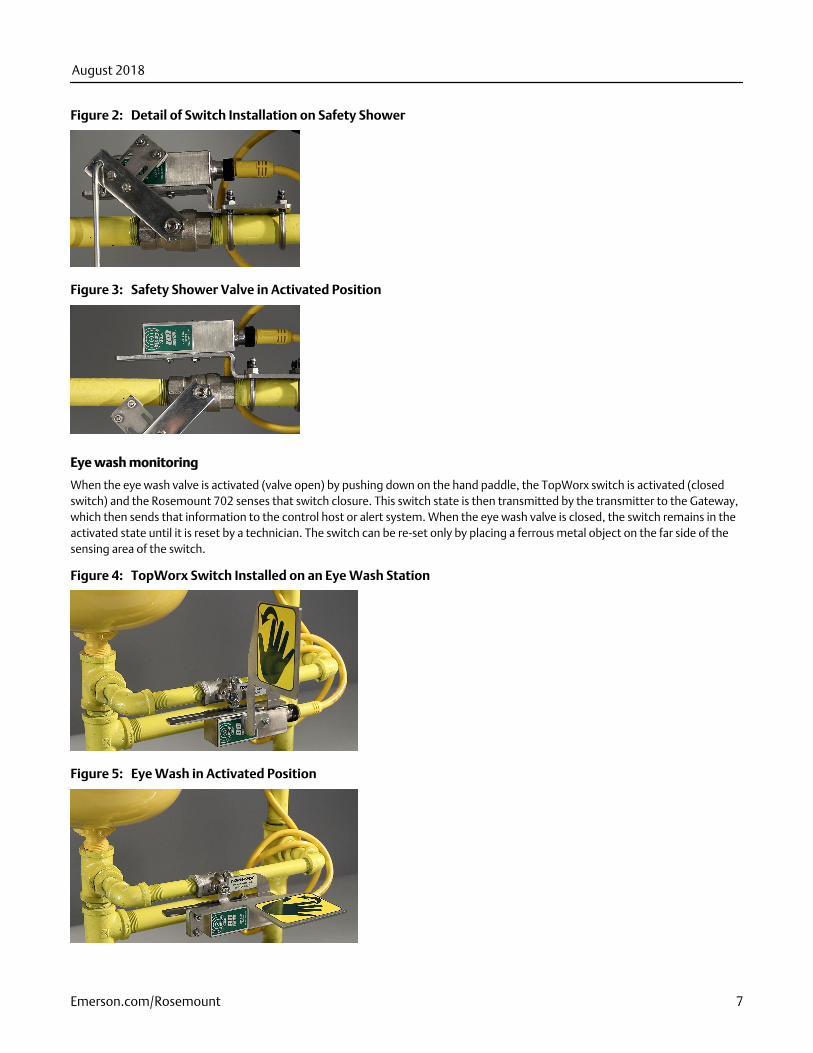
Detail of Switch Installation on Safety ShowerFigure 2:
Safety Shower Valve in Activated PositionFigure 3:
Eye wash monitoring
When the eye wash valve is activated (valve open) by pushing down on the hand paddle, the TopWorx switch is activated (closedswitch) and the Rosemount 702 senses that switch closure. This switch state is then transmitted by the transmitter to the Gateway,which then sends that information to the control host or alert system. When the eye wash valve is closed, the switch remains in theactivated state until it is reset by a technician. The switch can be re-set only by placing a ferrous metal object on the far side of thesensing area of the switch.
TopWorx Switch Installed on an Eye Wash StationFigure 4:
Eye Wash in Activated PositionFigure 5:
August 2018
Emerson.com/Rosemount 7
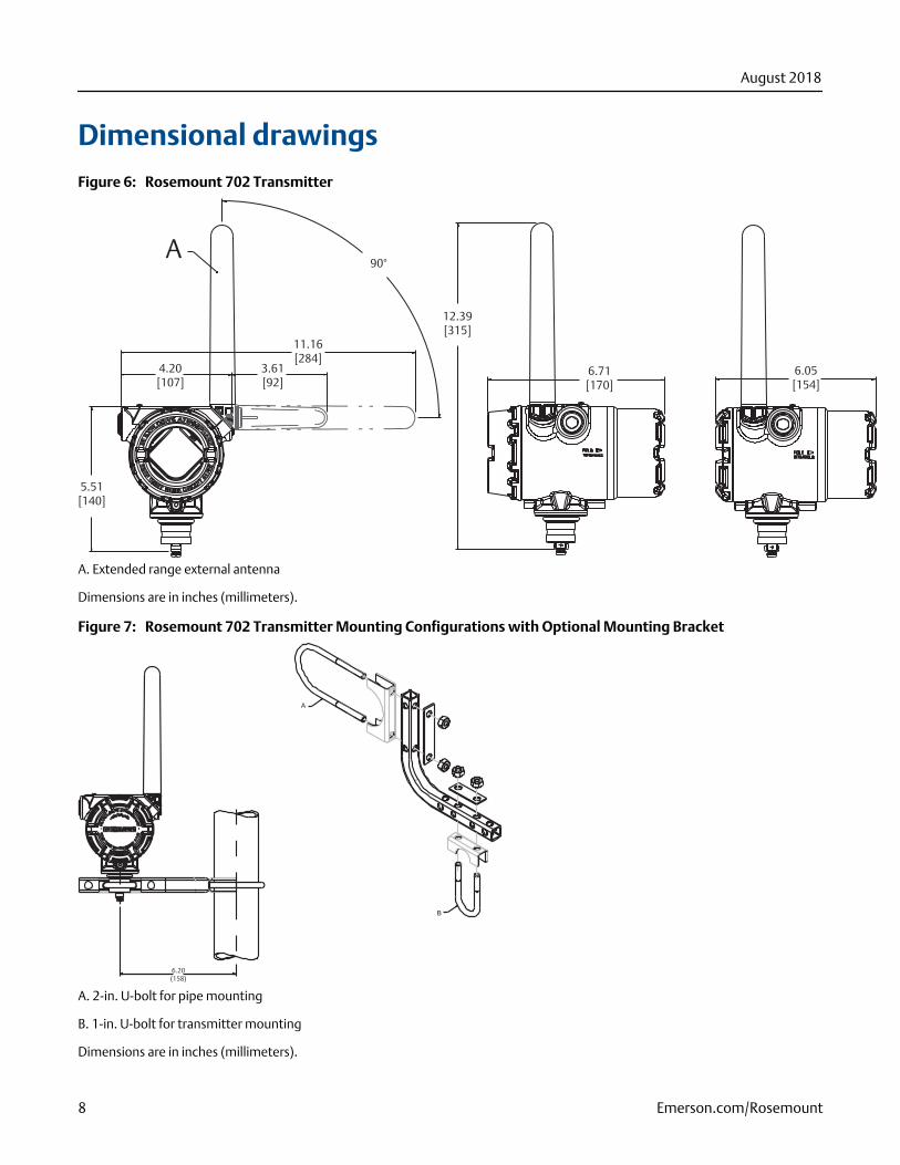
Dimensional drawingsRosemount 702 TransmitterFigure 6:
90°
11.16[284]
3.61[92]
4.20[107]
5.51[140]
12.39[315]
6.71[170]
6.05[154]
A
A. Extended range external antenna
Dimensions are in inches (millimeters).
Rosemount 702 Transmitter Mounting Configurations with Optional Mounting BracketFigure 7:
B
6.20(158)
A
A. 2-in. U-bolt for pipe mounting
B. 1-in. U-bolt for transmitter mounting
Dimensions are in inches (millimeters).
August 2018
8 Emerson.com/Rosemount

Rosemount 702 Wireless TransmitterFigure 8:
11.16[284]
90°
7.81[198]4.20
[107]
6.71[170]
6.05[154]11.23
[285]
7.88[200]
.42[11]
A
B
A
D
C
E
A. 2.4 GHz/WirelessHART® extended range antenna
B. Ground screw assembly
C. Digital display cover
D. Field terminals
E. Transmitter electronics
Dimensions are in inches (millimeters).
Rosemount 702 Wireless Transmitter Mounting Configuration with Optional Mounting BracketFigure 9:
A
3.67[93]
A. 2-in. U-bolt for pipe fitting
Dimensions are in inches (millimeters).
August 2018
Emerson.com/Rosemount 9
Specifications
Functional specifications
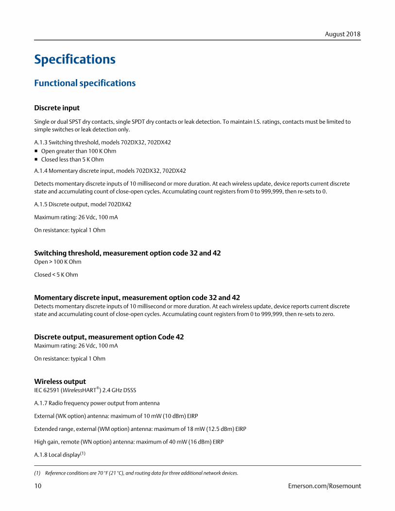
Discrete input
Single or dual SPST dry contacts, single SPDT dry contacts or leak detection. To maintain I.S. ratings, contacts must be limited tosimple switches or leak detection only.
A.1.3 Switching threshold, models 702DX32, 702DX42
■ Open greater than 100 K Ohm■ Closed less than 5 K Ohm
A.1.4 Momentary discrete input, models 702DX32, 702DX42
Detects momentary discrete inputs of 10 millisecond or more duration. At each wireless update, device reports current discretestate and accumulating count of close-open cycles. Accumulating count registers from 0 to 999,999, then re-sets to 0.
A.1.5 Discrete output, model 702DX42
Maximum rating: 26 Vdc, 100 mA
On resistance: typical 1 Ohm
Switching threshold, measurement option code 32 and 42Open > 100 K Ohm
Closed < 5 K Ohm
Momentary discrete input, measurement option code 32 and 42Detects momentary discrete inputs of 10 millisecond or more duration. At each wireless update, device reports current discretestate and accumulating count of close-open cycles. Accumulating count registers from 0 to 999,999, then re-sets to zero.
Discrete output, measurement option Code 42Maximum rating: 26 Vdc, 100 mA
On resistance: typical 1 Ohm
Wireless outputIEC 62591 (WirelessHART®) 2.4 GHz DSSS
A.1.7 Radio frequency power output from antenna
External (WK option) antenna: maximum of 10 mW (10 dBm) EIRP
Extended range, external (WM option) antenna: maximum of 18 mW (12.5 dBm) EIRP
High gain, remote (WN option) antenna: maximum of 40 mW (16 dBm) EIRP
A.1.8 Local display(1)
(1) Reference conditions are 70 °F (21 °C), and routing data for three additional network devices.
August 2018
10 Emerson.com/Rosemount
The optional integral LCD can display discrete state and diagnostic information. Display updates at each wireless update.
Radio frequency power output from antennaExternal (WK option) antenna: Maximum of 10 mW (10 dBm) EIRP
Extended range, external (WM option) antenna: Maximum of 18 mW (12.5 dBm) EIRP
Remote (WJ option) antenna: Maximum of 17 mW (12.3 dBm) EIRP
High-gain, remote (WN option) antenna: Maximum of 40 mW (16 dBm) EIRP
Local displayThe optional integral LCD display can show discrete state and diagnostic information. Display updates at each wireless update.
NoteThe option for a local display is not available with option 61, Liquid hydrocarbon leak detection.
Humidity limits0–100 percent relative humidity
Wireless update rate, measurement option code 32, 42, 52User selectable, 1 sec. to 60 min.
Wireless update rate, measurement option code 61User selectable, four seconds to 60 minutes
Wireless latching time, measurement option code 52User selectable 1 sec. to 10 min.
Physical specifications
Material selectionEmerson™ provides a variety of Rosemount™ products with various product options and configurations including materials ofconstruction that can be expected to perform well in a wide range of applications. The Rosemount product information presented isintended as a guide for the purchaser to make an appropriate selection for the application. It is the purchaser’s sole responsibility tomake a careful analysis of all process parameters (such as all chemical components, temperature, pressure, flow rate, abrasives,contaminants, etc.), when specifying product, materials, options and components for the particular application. Emerson is not in aposition to evaluate or guarantee the compatibility of the process fluid or other process parameters with the product, options,configuration or materials of construction selected.
Wireless power module electrical connectionsReplaceable, Intrinsically Safe Lithium-Thionyl Chloride power module with PBT polymer enclosure. Ten year life at one minuteupdate rate.
August 2018
Emerson.com/Rosemount 11
NoteReference conditions are 70 °F (21 °C), and routing data for three additional network devices.
NoteContinuous exposure to ambient temperature limits -40 °F or 185 °F (-40 °C or 85 °C) may reduce specified power module life by lessthan 20 percent.
Switch terminalsScrew terminals permanently fixed to terminal block
A.2.3 Field Communicator connections
Communication terminals
Clips permanently fixed to terminal block.
A.2.4 Materials of construction
Enclosure
■ Housing - low-copper aluminum, or stainless steel■ Paint - Polyurethane■ Cover O-ring - Buna-N
Field Communicator terminal connectionsClips permanently fixed to terminal block
Materials of construction
Enclosure
Housing: low-copper aluminum, or stainless steel
Paint: Polyurethane
Cover O-ring: Buna-N
Terminal block and power module pack
PBT
Antenna
PBT/PC integrated omni-directional antenna
Conduit entries½–14 NPT
Weight
Low-copper aluminum
Rosemount 702 without LCD display - 4.6 lb (2.0 kg)
August 2018
12 Emerson.com/Rosemount
Rosemount 702 with M5 LCD display - 4.7 lb (2.1 kg)
Stainless steel
Rosemount 702 without LCD display - 8.0 lb (3.6 kg)
Rosemount 702 with M5 LCD display - 8.1 lb (3.7 kg
Enclosure ratings (702)NEMA® 4X and IP66/67
MountingTransmitters may be attached directly to switch, brackets also permit remote mounting. See Dimensional drawings for moreinformation.
Performance specifications
Electromagnetic compatibility (EMC)Meets all industrial environment requirements of EN61326 and NAMUR NE-21. Maximum deviation <1% span during EMCdisturbance.(2)
Vibration effectWireless output unaffected when tested per the requirements of IEC60770-1 field or pipeline with high vibration level (10–60 Hz0.21 mm displacement peak amplitude/60–2000 Hz 3 g).
Wireless output unaffected when tested per the requirements of IEC60770-1 field with general application or pipeline with lowvibration level (10–60 Hz 0.15 mm displacement peak amplitude/60–500 Hz 2 g).
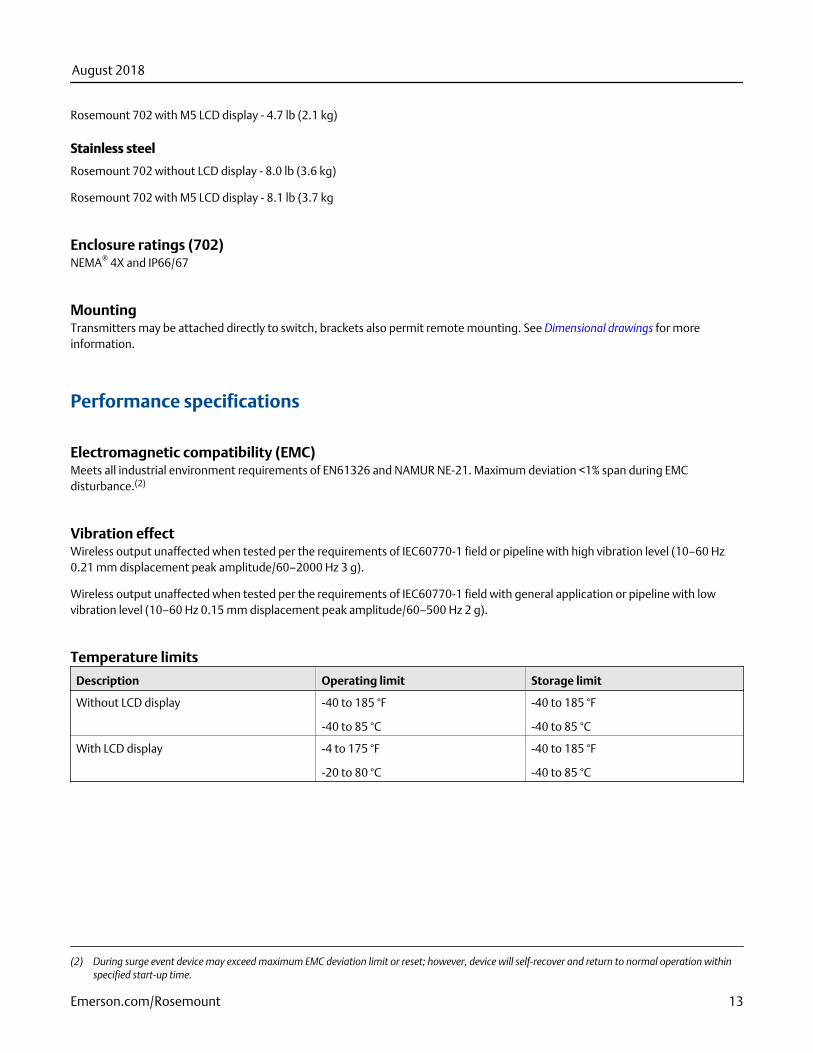
Temperature limits
Description Operating limit Storage limit
Without LCD display -40 to 185 °F
-40 to 85 °C
-40 to 185 °F
-40 to 85 °C
With LCD display -4 to 175 °F
-20 to 80 °C
-40 to 185 °F
-40 to 85 °C
(2) During surge event device may exceed maximum EMC deviation limit or reset; however, device will self-recover and return to normal operation withinspecified start-up time.
August 2018
Emerson.com/Rosemount 13
Wireless output specifications
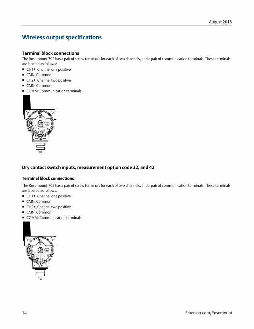
Terminal block connectionsThe Rosemount 702 has a pair of screw terminals for each of two channels, and a pair of communication terminals. These terminalsare labeled as follows:
■ CH1+: Channel one positive■ CMN: Common■ CH2+: Channel two positive■ CMN: Common■ COMM: Communication terminals
Dry contact switch inputs, measurement option code 32, and 42
Terminal block connections
The Rosemount 702 has a pair of screw terminals for each of two channels, and a pair of communication terminals. These terminalsare labeled as follows:
■ CH1+: Channel one positive■ CMN: Common■ CH2+: Channel two positive■ CMN: Common■ COMM: Communication terminals
August 2018
14 Emerson.com/Rosemount
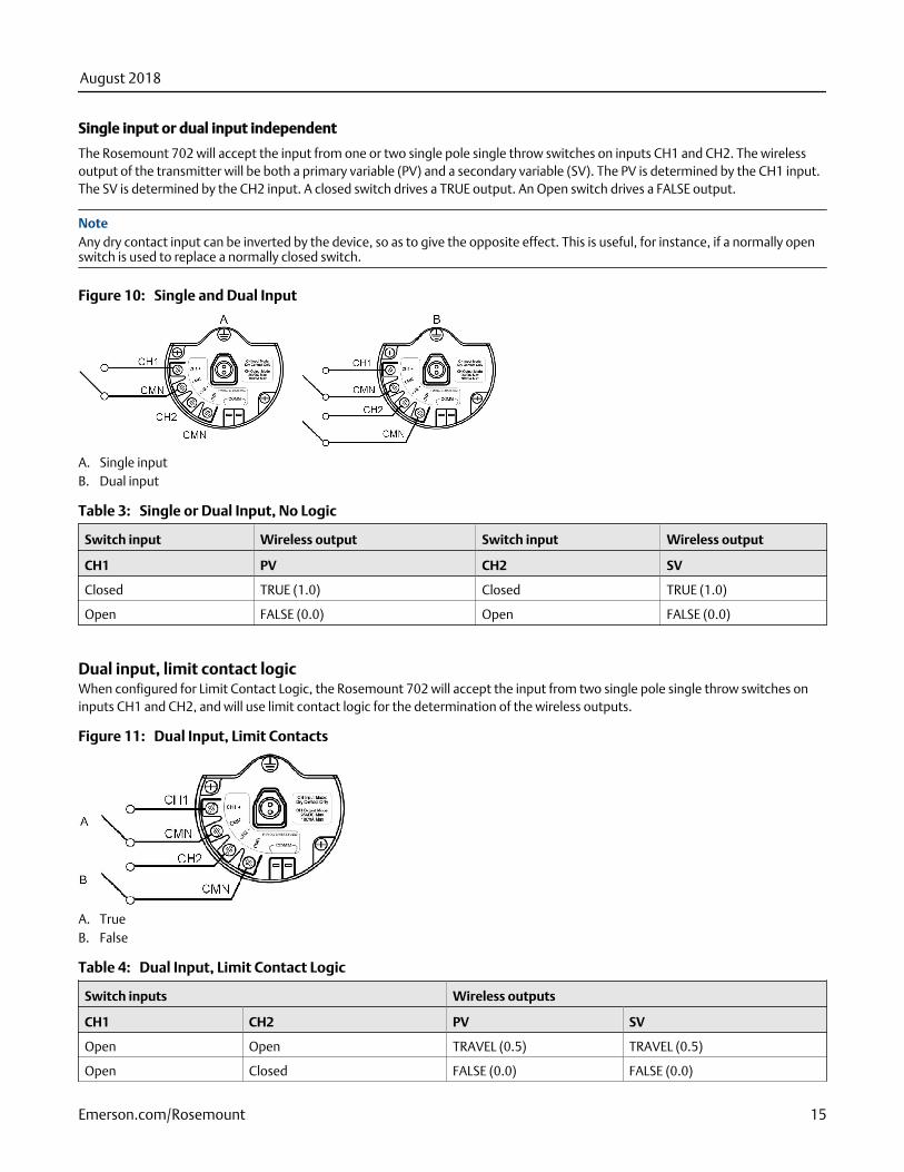
Single input or dual input independent
The Rosemount 702 will accept the input from one or two single pole single throw switches on inputs CH1 and CH2. The wirelessoutput of the transmitter will be both a primary variable (PV) and a secondary variable (SV). The PV is determined by the CH1 input.The SV is determined by the CH2 input. A closed switch drives a TRUE output. An Open switch drives a FALSE output.
NoteAny dry contact input can be inverted by the device, so as to give the opposite effect. This is useful, for instance, if a normally openswitch is used to replace a normally closed switch.
Single and Dual InputFigure 10:
A. Single inputB. Dual input
Single or Dual Input, No LogicTable 3:
Switch input Wireless output Switch input Wireless output
CH1 PV CH2 SV
Closed TRUE (1.0) Closed TRUE (1.0)
Open FALSE (0.0) Open FALSE (0.0)
Dual input, limit contact logicWhen configured for Limit Contact Logic, the Rosemount 702 will accept the input from two single pole single throw switches oninputs CH1 and CH2, and will use limit contact logic for the determination of the wireless outputs.
Dual Input, Limit ContactsFigure 11:
A. TrueB. False
Dual Input, Limit Contact LogicTable 4:
Switch inputs Wireless outputs
CH1 CH2 PV SV
Open Open TRAVEL (0.5) TRAVEL (0.5)
Open Closed FALSE (0.0) FALSE (0.0)
August 2018
Emerson.com/Rosemount 15
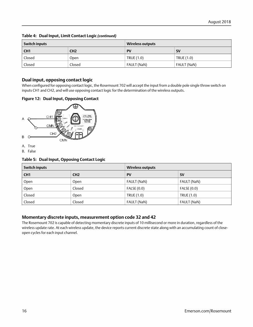
Dual Input, Limit Contact Logic (continued)Table 4:
Switch inputs Wireless outputs
CH1 CH2 PV SV
Closed Open TRUE (1.0) TRUE (1.0)
Closed Closed FAULT (NaN) FAULT (NaN)
Dual input, opposing contact logicWhen configured for opposing contact logic, the Rosemount 702 will accept the input from a double pole single throw switch oninputs CH1 and CH2, and will use opposing contact logic for the determination of the wireless outputs.
Dual Input, Opposing ContactFigure 12:
A. TrueB. False
Dual Input, Opposing Contact LogicTable 5:
Switch inputs Wireless outputs
CH1 CH2 PV SV
Open Open FAULT (NaN) FAULT (NaN)
Open Closed FALSE (0.0) FALSE (0.0)
Closed Open TRUE (1.0) TRUE (1.0)
Closed Closed FAULT (NaN) FAULT (NaN)
Momentary discrete inputs, measurement option code 32 and 42The Rosemount 702 is capable of detecting momentary discrete inputs of 10 millisecond or more in duration, regardless of thewireless update rate. At each wireless update, the device reports current discrete state along with an accumulating count of close-open cycles for each input channel.
August 2018
16 Emerson.com/Rosemount
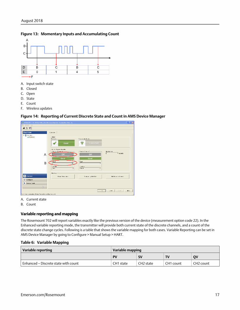
Momentary Inputs and Accumulating CountFigure 13:
A. Input switch stateB. ClosedC. OpenD. StateE. CountF. Wireless updates
Reporting of Current Discrete State and Count in AMS Device ManagerFigure 14:
A. Current stateB. Count
Variable reporting and mapping
The Rosemount 702 will report variables exactly like the previous version of the device (measurement option code 22). In theEnhanced variable reporting mode, the transmitter will provide both current state of the discrete channels, and a count of thediscrete state change cycles. Following is a table that shows the variable mapping for both cases. Variable Reporting can be set inAMS Device Manager by going to Configure > Manual Setup > HART.
Variable MappingTable 6:
Variable reporting Variable mapping
PV SV TV QV
Enhanced – Discrete state with count CH1 state CH2 state CH1 count CH2 count
August 2018
Emerson.com/Rosemount 17
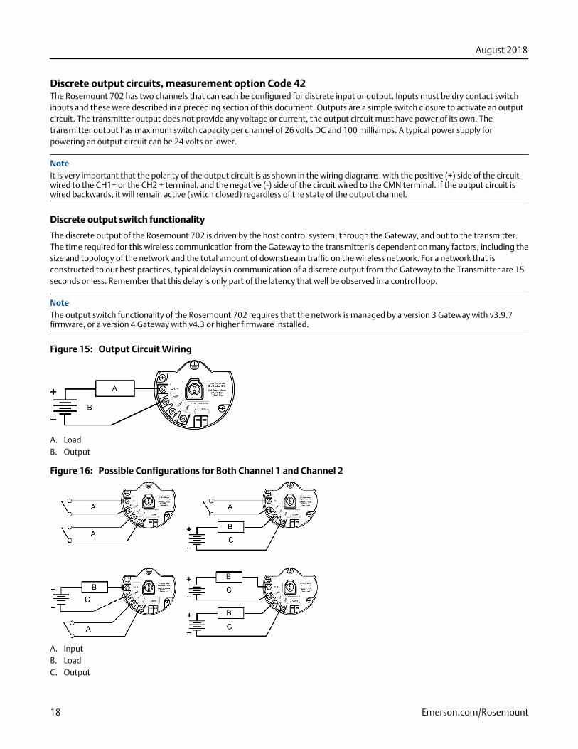
Discrete output circuits, measurement option Code 42The Rosemount 702 has two channels that can each be configured for discrete input or output. Inputs must be dry contact switchinputs and these were described in a preceding section of this document. Outputs are a simple switch closure to activate an outputcircuit. The transmitter output does not provide any voltage or current, the output circuit must have power of its own. Thetransmitter output has maximum switch capacity per channel of 26 volts DC and 100 milliamps. A typical power supply forpowering an output circuit can be 24 volts or lower.
NoteIt is very important that the polarity of the output circuit is as shown in the wiring diagrams, with the positive (+) side of the circuitwired to the CH1+ or the CH2 + terminal, and the negative (-) side of the circuit wired to the CMN terminal. If the output circuit iswired backwards, it will remain active (switch closed) regardless of the state of the output channel.
Discrete output switch functionality
The discrete output of the Rosemount 702 is driven by the host control system, through the Gateway, and out to the transmitter.The time required for this wireless communication from the Gateway to the transmitter is dependent on many factors, including thesize and topology of the network and the total amount of downstream traffic on the wireless network. For a network that isconstructed to our best practices, typical delays in communication of a discrete output from the Gateway to the Transmitter are 15seconds or less. Remember that this delay is only part of the latency that well be observed in a control loop.
NoteThe output switch functionality of the Rosemount 702 requires that the network is managed by a version 3 Gateway with v3.9.7firmware, or a version 4 Gateway with v4.3 or higher firmware installed.
Output Circuit WiringFigure 15:
A. LoadB. Output
Possible Configurations for Both Channel 1 and Channel 2Figure 16:
A. InputB. LoadC. Output
August 2018
18 Emerson.com/Rosemount
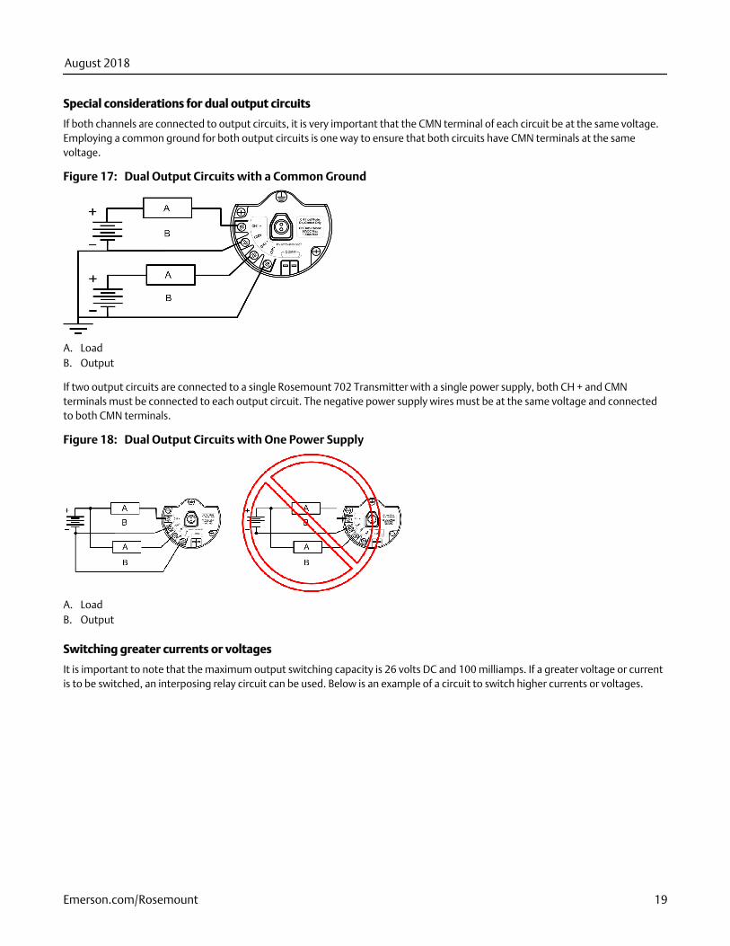
Special considerations for dual output circuits
If both channels are connected to output circuits, it is very important that the CMN terminal of each circuit be at the same voltage.Employing a common ground for both output circuits is one way to ensure that both circuits have CMN terminals at the samevoltage.
Dual Output Circuits with a Common GroundFigure 17:
A. LoadB. Output
If two output circuits are connected to a single Rosemount 702 Transmitter with a single power supply, both CH + and CMNterminals must be connected to each output circuit. The negative power supply wires must be at the same voltage and connectedto both CMN terminals.
Dual Output Circuits with One Power SupplyFigure 18:
A. LoadB. Output
Switching greater currents or voltages
It is important to note that the maximum output switching capacity is 26 volts DC and 100 milliamps. If a greater voltage or currentis to be switched, an interposing relay circuit can be used. Below is an example of a circuit to switch higher currents or voltages.
August 2018
Emerson.com/Rosemount 19
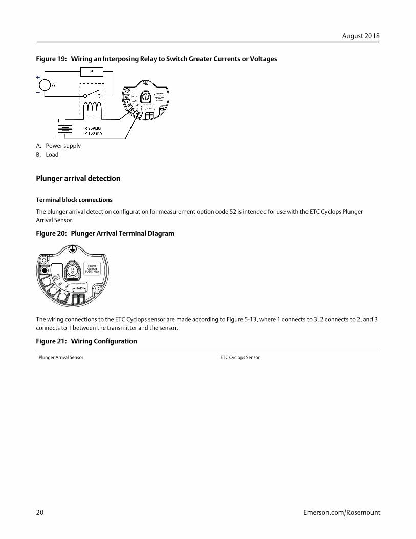
Wiring an Interposing Relay to Switch Greater Currents or VoltagesFigure 19:
A. Power supplyB. Load
Plunger arrival detection
Terminal block connections
The plunger arrival detection configuration for measurement option code 52 is intended for use with the ETC Cyclops PlungerArrival Sensor.
Plunger Arrival Terminal DiagramFigure 20:
The wiring connections to the ETC Cyclops sensor are made according to Figure 5-13, where 1 connects to 3, 2 connects to 2, and 3connects to 1 between the transmitter and the sensor.
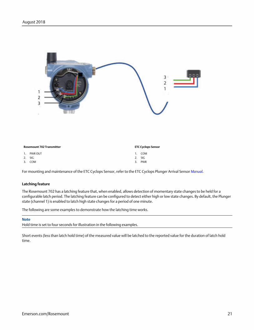
Wiring ConfigurationFigure 21:
Plunger Arrival Sensor ETC Cyclops Sensor
August 2018
20 Emerson.com/Rosemount
1
2
3
3
2
1
Rosemount 702 Transmitter ETC Cyclops Sensor
1. PWR OUT2. SIG3. COM
1. COM2. SIG3. PWR
For mounting and maintenance of the ETC Cyclops Sensor, refer to the ETC Cyclops Plunger Arrival Sensor Manual.
Latching feature
The Rosemount 702 has a latching feature that, when enabled, allows detection of momentary state changes to be held for aconfigurable latch period. The latching feature can be configured to detect either high or low state changes. By default, the Plungerstate (channel 1) is enabled to latch high state changes for a period of one minute.
The following are some examples to demonstrate how the latching time works.
NoteHold time is set to four seconds for illustration in the following examples.
Short events (less than latch hold time) of the measured value will be latched to the reported value for the duration of latch holdtime.
August 2018
Emerson.com/Rosemount 21
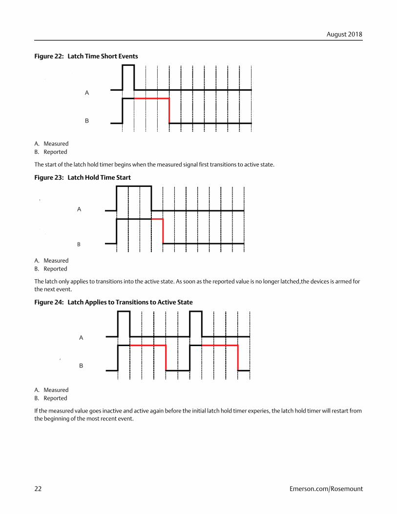
Latch Time Short EventsFigure 22:
A
B
A. MeasuredB. Reported
The start of the latch hold timer begins when the measured signal first transitions to active state.
Latch Hold Time StartFigure 23:
A
B
A. MeasuredB. Reported
The latch only applies to transitions into the active state. As soon as the reported value is no longer latched,the devices is armed forthe next event.
Latch Applies to Transitions to Active StateFigure 24:
A
B
A. MeasuredB. Reported
If the measured value goes inactive and active again before the initial latch hold timer experies, the latch hold timer will restart fromthe beginning of the most recent event.
August 2018
22 Emerson.com/Rosemount
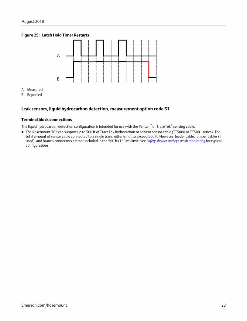
Latch Hold Timer RestartsFigure 25:
A
B
A. MeasuredB. Reported
Leak sensors, liquid hydrocarbon detection, measurement option code 61
Terminal block connections
The liquid hydrocarbon detection configuration is intended for use with the Pentair™ or TraceTek® sensing cable.
■ The Rosemount 702 can support up to 500 ft of TraceTek hydrocarbon or solvent sensor cable (TT5000 or TT5001 series). Thetotal amount of sensor cable connected to a single transmitter is not to exceed 500 ft. However, leader cable, jumper cables (ifused), and branch connectors are not included in the 500 ft (150 m) limit. See Safety shower and eye wash monitoring for typicalconfigurations.
August 2018
Emerson.com/Rosemount 23
Product certifications
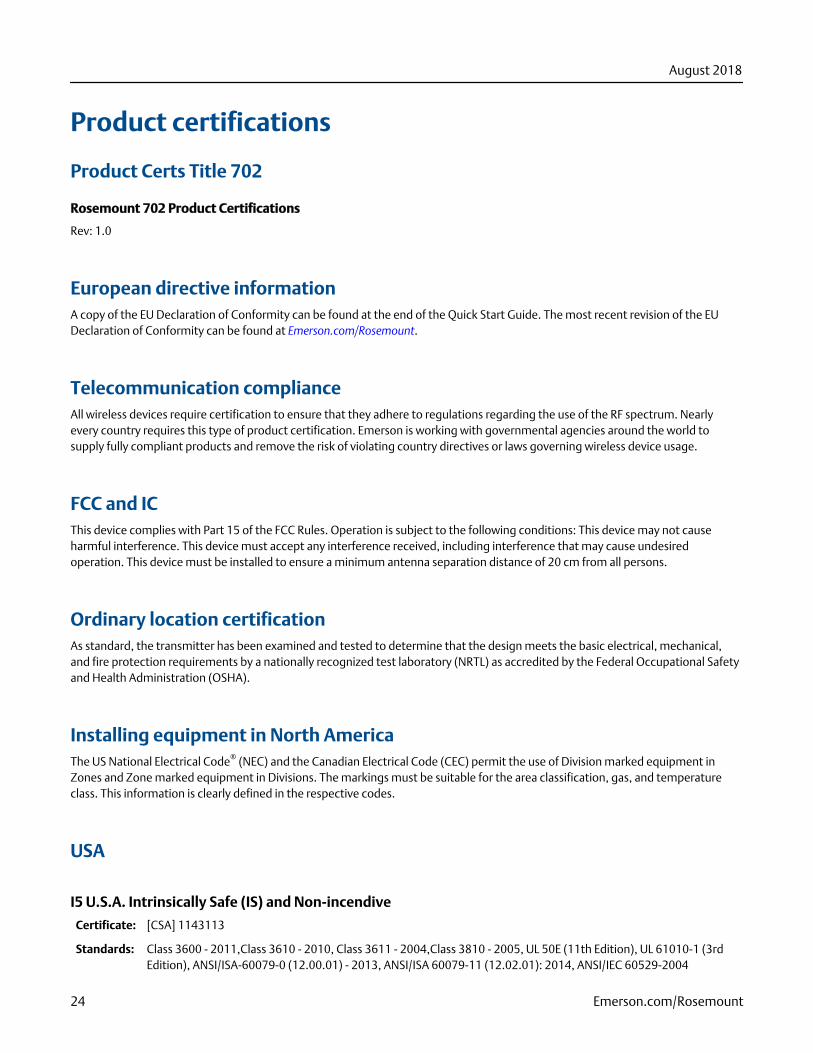
Product Certs Title 702
Rosemount 702 Product Certifications
Rev: 1.0
European directive informationA copy of the EU Declaration of Conformity can be found at the end of the Quick Start Guide. The most recent revision of the EUDeclaration of Conformity can be found at Emerson.com/Rosemount.
Telecommunication complianceAll wireless devices require certification to ensure that they adhere to regulations regarding the use of the RF spectrum. Nearlyevery country requires this type of product certification. Emerson is working with governmental agencies around the world tosupply fully compliant products and remove the risk of violating country directives or laws governing wireless device usage.
FCC and ICThis device complies with Part 15 of the FCC Rules. Operation is subject to the following conditions: This device may not causeharmful interference. This device must accept any interference received, including interference that may cause undesiredoperation. This device must be installed to ensure a minimum antenna separation distance of 20 cm from all persons.
Ordinary location certificationAs standard, the transmitter has been examined and tested to determine that the design meets the basic electrical, mechanical,and fire protection requirements by a nationally recognized test laboratory (NRTL) as accredited by the Federal Occupational Safetyand Health Administration (OSHA).
Installing equipment in North AmericaThe US National Electrical Code® (NEC) and the Canadian Electrical Code (CEC) permit the use of Division marked equipment inZones and Zone marked equipment in Divisions. The markings must be suitable for the area classification, gas, and temperatureclass. This information is clearly defined in the respective codes.
USA
I5 U.S.A. Intrinsically Safe (IS) and Non-incendive
Certificate: [CSA] 1143113
Standards: Class 3600 - 2011,Class 3610 - 2010, Class 3611 - 2004,Class 3810 - 2005, UL 50E (11th Edition), UL 61010-1 (3rdEdition), ANSI/ISA-60079-0 (12.00.01) - 2013, ANSI/ISA 60079-11 (12.02.01): 2014, ANSI/IEC 60529-2004
August 2018
24 Emerson.com/Rosemount
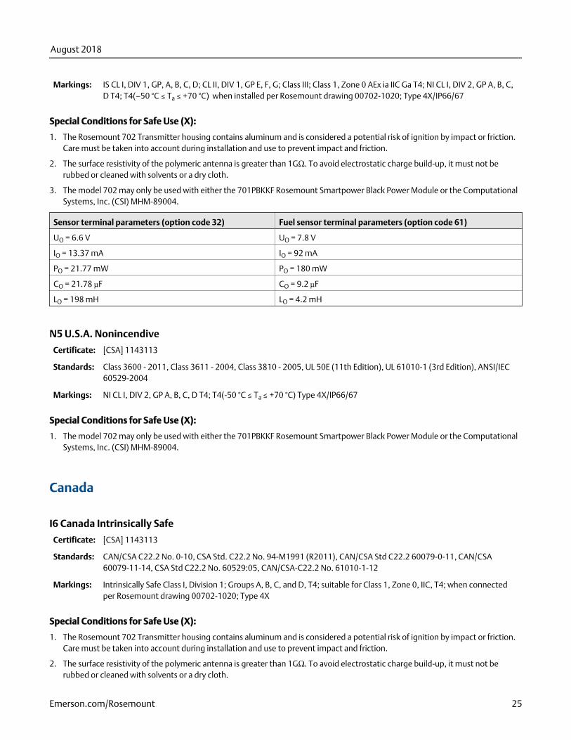
Markings: IS CL I, DIV 1, GP, A, B, C, D; CL II, DIV 1, GP E, F, G; Class III; Class 1, Zone 0 AEx ia IIC Ga T4; NI CL I, DIV 2, GP A, B, C,D T4; T4(–50 °C ≤ Ta ≤ +70 °C) when installed per Rosemount drawing 00702-1020; Type 4X/IP66/67
Special Conditions for Safe Use (X):
1. The Rosemount 702 Transmitter housing contains aluminum and is considered a potential risk of ignition by impact or friction.Care must be taken into account during installation and use to prevent impact and friction.
2. The surface resistivity of the polymeric antenna is greater than 1GΩ. To avoid electrostatic charge build-up, it must not berubbed or cleaned with solvents or a dry cloth.
3. The model 702 may only be used with either the 701PBKKF Rosemount Smartpower Black Power Module or the ComputationalSystems, Inc. (CSI) MHM-89004.
Sensor terminal parameters (option code 32) Fuel sensor terminal parameters (option code 61)
UO = 6.6 V UO = 7.8 V
IO = 13.37 mA IO = 92 mA
PO = 21.77 mW PO = 180 mW
CO = 21.78 µF CO = 9.2 µF
LO = 198 mH LO = 4.2 mH
N5 U.S.A. Nonincendive
Certificate: [CSA] 1143113
Standards: Class 3600 - 2011, Class 3611 - 2004, Class 3810 - 2005, UL 50E (11th Edition), UL 61010-1 (3rd Edition), ANSI/IEC60529-2004
Markings: NI CL I, DIV 2, GP A, B, C, D T4; T4(-50 °C ≤ Ta ≤ +70 °C) Type 4X/IP66/67
Special Conditions for Safe Use (X):
1. The model 702 may only be used with either the 701PBKKF Rosemount Smartpower Black Power Module or the ComputationalSystems, Inc. (CSI) MHM-89004.
Canada
I6 Canada Intrinsically Safe
Certificate: [CSA] 1143113
Standards: CAN/CSA C22.2 No. 0-10, CSA Std. C22.2 No. 94-M1991 (R2011), CAN/CSA Std C22.2 60079-0-11, CAN/CSA60079-11-14, CSA Std C22.2 No. 60529:05, CAN/CSA-C22.2 No. 61010-1-12
Markings: Intrinsically Safe Class I, Division 1; Groups A, B, C, and D, T4; suitable for Class 1, Zone 0, IIC, T4; when connectedper Rosemount drawing 00702-1020; Type 4X
Special Conditions for Safe Use (X):
1. The Rosemount 702 Transmitter housing contains aluminum and is considered a potential risk of ignition by impact or friction.Care must be taken into account during installation and use to prevent impact and friction.
2. The surface resistivity of the polymeric antenna is greater than 1GΩ. To avoid electrostatic charge build-up, it must not berubbed or cleaned with solvents or a dry cloth.
August 2018
Emerson.com/Rosemount 25
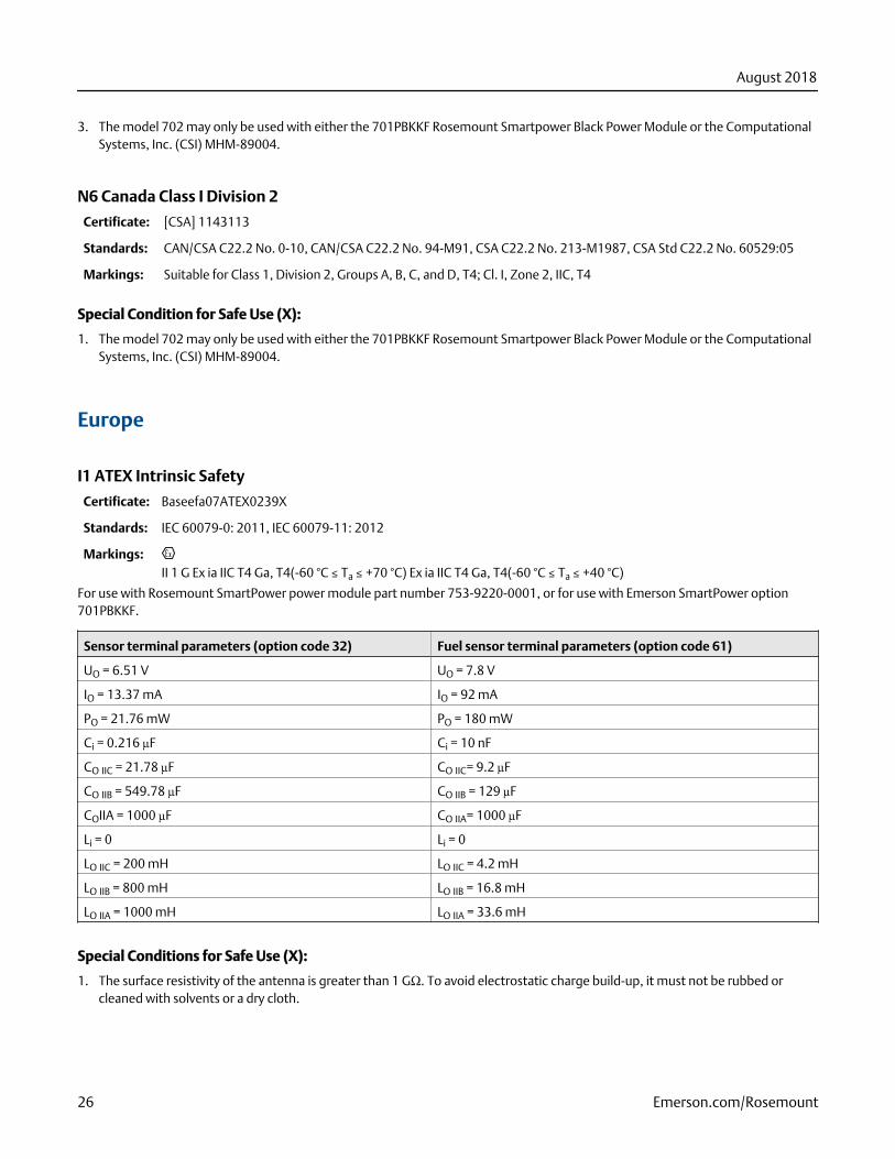
3. The model 702 may only be used with either the 701PBKKF Rosemount Smartpower Black Power Module or the ComputationalSystems, Inc. (CSI) MHM-89004.
N6 Canada Class I Division 2
Certificate: [CSA] 1143113
Standards: CAN/CSA C22.2 No. 0-10, CAN/CSA C22.2 No. 94-M91, CSA C22.2 No. 213-M1987, CSA Std C22.2 No. 60529:05
Markings: Suitable for Class 1, Division 2, Groups A, B, C, and D, T4; Cl. I, Zone 2, IIC, T4
Special Condition for Safe Use (X):
1. The model 702 may only be used with either the 701PBKKF Rosemount Smartpower Black Power Module or the ComputationalSystems, Inc. (CSI) MHM-89004.
Europe
I1 ATEX Intrinsic Safety
Certificate: Baseefa07ATEX0239X
Standards: IEC 60079-0: 2011, IEC 60079-11: 2012
Markings:II 1 G Ex ia IIC T4 Ga, T4(-60 °C ≤ Ta ≤ +70 °C) Ex ia IIC T4 Ga, T4(-60 °C ≤ Ta ≤ +40 °C)
For use with Rosemount SmartPower power module part number 753-9220-0001, or for use with Emerson SmartPower option701PBKKF.
Sensor terminal parameters (option code 32) Fuel sensor terminal parameters (option code 61)
UO = 6.51 V UO = 7.8 V
IO = 13.37 mA IO = 92 mA
PO = 21.76 mW PO = 180 mW
Ci = 0.216 µF Ci = 10 nF
CO IIC = 21.78 µF CO IIC= 9.2 µF
CO IIB = 549.78 µF CO IIB = 129 µF
COIIA = 1000 µF CO IIA= 1000 µF
Li = 0 Li = 0
LO IIC = 200 mH LO IIC = 4.2 mH
LO IIB = 800 mH LO IIB = 16.8 mH
LO IIA = 1000 mH LO IIA = 33.6 mH
Special Conditions for Safe Use (X):
1. The surface resistivity of the antenna is greater than 1 GΩ. To avoid electrostatic charge build-up, it must not be rubbed orcleaned with solvents or a dry cloth.
August 2018
26 Emerson.com/Rosemount
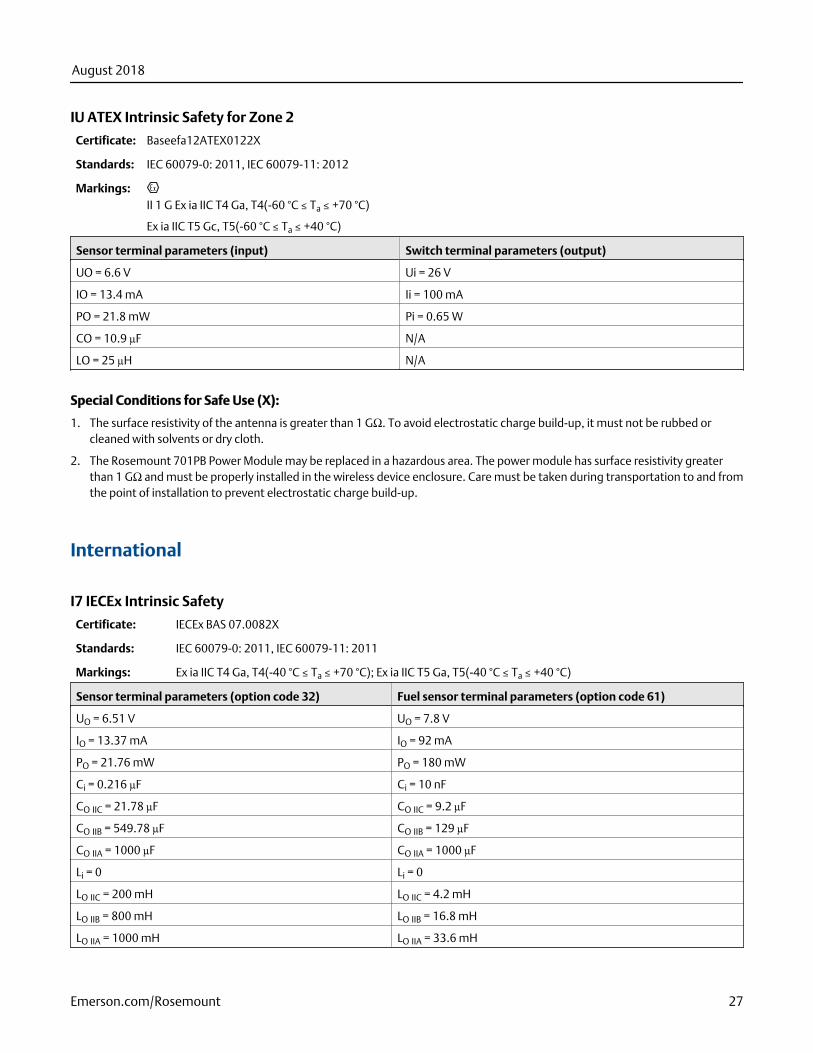
IU ATEX Intrinsic Safety for Zone 2
Certificate: Baseefa12ATEX0122X
Standards: IEC 60079-0: 2011, IEC 60079-11: 2012
Markings:II 1 G Ex ia IIC T4 Ga, T4(-60 °C ≤ Ta ≤ +70 °C)
Ex ia IIC T5 Gc, T5(-60 °C ≤ Ta ≤ +40 °C)
Sensor terminal parameters (input) Switch terminal parameters (output)
UO = 6.6 V Ui = 26 V
IO = 13.4 mA Ii = 100 mA
PO = 21.8 mW Pi = 0.65 W
CO = 10.9 µF N/A
LO = 25 µH N/A
Special Conditions for Safe Use (X):
1. The surface resistivity of the antenna is greater than 1 GΩ. To avoid electrostatic charge build-up, it must not be rubbed orcleaned with solvents or dry cloth.
2. The Rosemount 701PB Power Module may be replaced in a hazardous area. The power module has surface resistivity greaterthan 1 GΩ and must be properly installed in the wireless device enclosure. Care must be taken during transportation to and fromthe point of installation to prevent electrostatic charge build-up.
International
I7 IECEx Intrinsic Safety
Certificate: IECEx BAS 07.0082X
Standards: IEC 60079-0: 2011, IEC 60079-11: 2011
Markings: Ex ia IIC T4 Ga, T4(-40 °C ≤ Ta ≤ +70 °C); Ex ia IIC T5 Ga, T5(-40 °C ≤ Ta ≤ +40 °C)
Sensor terminal parameters (option code 32) Fuel sensor terminal parameters (option code 61)
UO = 6.51 V UO = 7.8 V
IO = 13.37 mA IO = 92 mA
PO = 21.76 mW PO = 180 mW
Ci = 0.216 µF Ci = 10 nF
CO IIC = 21.78 µF CO IIC = 9.2 µF
CO IIB = 549.78 µF CO IIB = 129 µF
CO IIA = 1000 µF CO IIA = 1000 µF
Li = 0 Li = 0
LO IIC = 200 mH LO IIC = 4.2 mH
LO IIB = 800 mH LO IIB = 16.8 mH
LO IIA = 1000 mH LO IIA = 33.6 mH
August 2018
Emerson.com/Rosemount 27

Special Conditions for Safe Use (X):
1. The surface resistivity of the antenna is greater than 1 GΩ. To avoid electrostatic charge build-up, it must not be rubbed orcleaned with solvents or dry cloth.
2. The Rosemount 701PBKKF Power Module may be replaced in a hazardous area. The power modules have a surface resistivitygreater than 1GΩ and must be properly installed I the wireless device enclosure. Care must be taken during transportation toand from the point of installation to prevent electrostatic charge build-up.
3. The Rosemount 702 enclosure may be made of aluminum alloy and given a protective polyurethane paint finish; however, careshould be taken to protect it from impact or abrasion if located in a Zone 0 area.
IY IECEx Intrinsic Safety for Zone 2
Certificate: IECEx BAS 12.0082X
Standards: IEC 60079-0: 2011, IEC 60079-11: 2011
Markings: Ex nA IIC T4 Gc, T4(-40 °C ≤ Ta ≤ +70 °C); Ex nA IIC T5 Gc, T5(-40 °C ≤ Ta ≤ +40 °C)
Sensor terminal parameters (input)
Switch terminal parameters
(output)
UO = 6.6 V Ui = 26 V
IO = 13.4 mA Ii = 100 mA
PO = 21.8 mW Pi = 0.65 W
CO = 10.9 µF N/A
LO = 25 µH N/A
Special Conditions for Safe Use (X):
1. The surface resistivity of the antenna is greater than 1 GΩ. To avoid electrostatic charge build-up, it must not be rubbed orcleaned with solvents or dry cloth.
2. The Rosemount 701PBKKF Power Module may be replaced in a hazardous area. The power modules have a surface resistivitygreater than 1 GΩ and must be properly installed I the wireless device enclosure. Care must be taken during transportation toand from the point of installation to prevent electrostatic charge build-up.
3. The Rosemount 702 enclosure may be made of aluminum alloy and given a protective polyurethane paint finish; however, careshould be taken to protect it from impact or abrasion if located in a Zone 0 area.
China
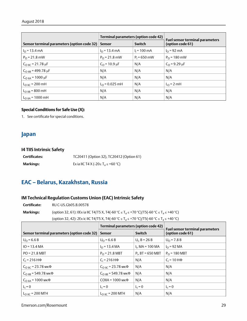
I3 China Intrinsic Safety
Certificate: GYJ18.1330X
Standards: GB3836.1-2010, GB3836.4-2010, GB3836.20-2010
Markings: (option 32, 61): Ex ia IIC T4/T5 Ga, T4(-60 ≤ Ta ≤ 70 °C)/T5(-60 ≤ Ta ≤ 40 °C)
(option 32, 42): Ex ic IIC T4/T5 Gc, T4(-60 ≤ Ta ≤ 70 °C)/T5(-60 ≤ Ta ≤ 40 °C)
Sensor terminal parameters (option code 32)
Terminal parameters (option code 42)Fuel sensor terminal parameters(option code 61)Sensor Switch
UO = 6.6 V UO = 6.6 V Ui = 26 V UO = 7.8 V
August 2018
28 Emerson.com/Rosemount
Sensor terminal parameters (option code 32)
Terminal parameters (option code 42)Fuel sensor terminal parameters(option code 61)Sensor Switch
IO = 13.4 mA IO = 13.4 mA Ii = 100 mA IO = 92 mA
PO = 21.8 mW PO = 21.8 mW Pi = 650 mW PO = 180 mW
CO IIC = 21.78 µF CO = 10.9 µF N/A CO = 9.29 µF
CO IIB = 499.78 µF N/A N/A N/A
CO IIA = 1000 µF N/A N/A N/A
LO IIC = 200 mH LO = 0.025 mH N/A LO = 2 mH
LO IIB = 800 mH N/A N/A N/A
LO IIA = 1000 mH N/A N/A N/A
Special Conditions for Safe Use (X):
1. See certificate for special conditions.
Japan
I4 TIIS Intrinsic Safety
Certificates: TC20411 (Option 32), TC20412 (Option 61)
Markings: Ex ia IIC T4 X (-20≤ Ta ≤ +60 °C)
EAC – Belarus, Kazakhstan, Russia
IM Technical Regulation Customs Union (EAC) Intrinsic Safety
Certificate: RU C-US.Gb05.B.00578
Markings: (option 32, 61): 0Ex ia IIC T4/T5 X, T4(-60 °C ≤ Ta ≤ +70 °C)/T5(-60 °C ≤ Ta ≤ +40 °C)
(option 32, 42): 2Ex ic IIC T4/T5 X, T4(-60 °C ≤ Ta ≤ +70 °C)/T5(-60 °C ≤ Ta ≤ +40 °C)
Sensor terminal parameters (option code 32)
Terminal parameters (option code 42)Fuel sensor terminal parameters(option code 61)Sensor Switch
UO = 6.6 B UO = 6.6 B Ui, B = 26 B UO = 7.8 B
IO = 13.4 MA IO = 13.4 MA Ii, MA = 100 MA IO = 92 MA
PO = 21.8 MBT PO = 21.8 MBT Pi, BT = 650 MBT PO = 180 MBT
Ci = 216 HΦ Ci = 216 HΦ N/A Ci = 10 HΦ
CO IIC = 23.78 мкΦ CO IIC = 23.78 мкΦ N/A N/A
CO IIB = 549.78 мкΦ CO IIB = 549.78 мкΦ N/A N/A
CO IIA = 1000 мкΦ COIIA = 1000 мкΦ N/A N/A
Li = 0 Li = 0 Li = 0 Li = 0
LO IIC = 200 MГH LO IIC = 200 MГH N/A N/A
August 2018
Emerson.com/Rosemount 29
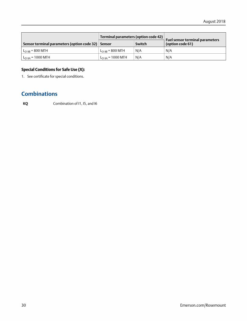
Sensor terminal parameters (option code 32)
Terminal parameters (option code 42)Fuel sensor terminal parameters(option code 61)Sensor Switch
LO IIB = 800 MГH LO IIB = 800 MГH N/A N/A
LO IIA = 1000 MГH LO IIA = 1000 MГH N/A N/A
Special Conditions for Safe Use (X):
1. See certificate for special conditions.
Combinations
KQ Combination of I1, I5, and I6
August 2018
30 Emerson.com/Rosemount

August 2018
Emerson.com/Rosemount 31
00813-0100-4702, Rev KC Product Data SheetAugust 2018
Global HeadquartersEmerson Automation Solutions6021 Innovation BlvdShakopee, MN 55379 USA
+1 800 999 9307 or +1 952 906 8888
+1 952 949 7001
North America Regional OfficeEmerson Automation Solutions8200 Market Blvd.Chanhassen, MN 55317, USA
+1 800 999 9307 or +1 952 906 8888
+1 952 949 7001
Latin America Regional OfficeEmerson Automation SolutionsSunrise, FL 33323, USA
T +1 954 846 5030
+1 954 846 5121
Europe Regional OfficeEmerson Automation Solutions EuropeGmbHNeuhofstrasse 19a P.O. Box 1046CH 6340 BaarSwitzerland
T +41 (0) 41 768 6111
+41 (0) 41 768 6300
Asia Pacific Regional OfficeEmerson Automation Solutions1 Pandan CrescentSingapore 128461Republic of Singapore
+65 6777 8211
+65 6777 0947
Middle East and Africa Regional OfficeEmerson Automation SolutionsEmerson FZE P.O. Box 17033Jebel Ali Free Zone - South 2Dubai, United Arab Emirates
+971 4 8118100
+971 4 8865465
Linkedin.com/company/Emerson-Automation-Solutions
Twitter.com/Rosemount_News
Facebook.com/Rosemount
Youtube.com/user/RosemountMeasurement
Google.com/+RosemountMeasurement
©2018 Emerson. All rights reserved.
Emerson Terms and Conditions of Sale are available upon request. The Emerson logo isa trademark and service mark of Emerson Electric Co. Rosemount is mark of one of theEmerson family of companies. All other marks are the property of their respectiveowners.