Embed Size (px)
Citation preview
AUGUST 1972
HEWLETT-PACKARD JOURNAL
© Copr. 1949-1998 Hewlett-Packard Co.
Compactness and Versatility in a New Plug -Together Digital Multimeter A new 4V2 digi t Mult imeter is constructed in sect ions that p lug together to form a compact ins t rument , g iv ing the user a cho ice of capabilit ies. By Albert Gookin
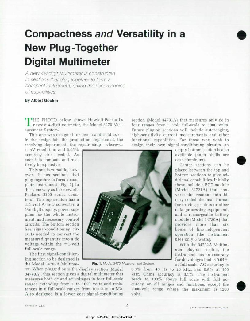
THE PHOTO below shows Hewlett-Packard's newest 4-digit voltmeter, the Model 3470 Mea
surement System. This one was designed for bench and field use —
in the design lab, the production department, the receiving department, the repair shop — wherever 1-mV resolution and 0.05% accuracy are needed. As such it is compact, and rela tively inexpensive.
This one is versatile, how ever. I t has sect ions that plug together to form a com plete instrument (Fig. 3) in the same way as the Hewlett- Packard 5300 series coun ters1. The top section has a ±l-volt A-to-D converter, a 4VÃ2 -digit display, power sup plies for the whole instru ment, and necessary control circuits. The bottom section has signal-conditioning cir cuits needed to convert the measured quantity into a dc voltage within the ±l-volt full-scale range.
The first signal-condition ing section to be designed is the Model 34702A Multime ter. When plugged onto the display section (Model 34740A), this section gives a digital multimeter that measures both dc and ac voltages in four full-scale ranges extending from 1 to 1000 volts and resis tances in 6 full-scale ranges from 100 fi to 10 Mfi. Also designed is a lower cost signal-conditioning
section (Model 34701A) that measures only dc in four ranges from 1 volt full-scale to 1000 volts. Future plug-on sections will include autoranging, high-sensitivity current measurements and other functional capabilities. For those who wish to design their own signal-conditioning circuits, an
empty bottom section is also available (outer shells are cast aluminum).
Center sections can be placed between the top and bottom sections to give ad ditional capabilities. Initially these include a BCD module (Model 34721A) that con verts the readout into bi nary-coded decimal format for driving printers or other data processing equipment, and a rechargeable battery module (Model 34720A) that p rov ides more t han s ix hours of line-independent operation (the instrument uses only 5 watts).
With the 34702A Multim eter plug-on section, the instrument has an accuracy for dc voltages that is 0.04% at full scale. AC accuracy is 20 kHz, and 0.8% at 100 is 0.1%. The instrument
full scale with full ac-
Fig . 1 . Mode l 3470 Measurement Sys tem.
0.3% from 45 Hz to kHz. Ohms accuracy reads to 100% above curacy on all ranges and functions, except the 1000-volt range where the maximum is 1200 volts.
P R I N T E D I N U . S . A . Ã ‡ H E W L E T T - P A C K A R D C O M P A N Y , 1 9 7 2
© Copr. 1949-1998 Hewlett-Packard Co.

F i g . 2 . M o d e l 3 4 7 0 M e a s u r e m e n t S y s t e m c o n s i s t s o l d i s p lay sec t ion and va r ious s igna l -cond i t i on ing sec t ions ( two a t t ime oà w r i t i ng ) p lus ba t te ry and BCD ou tpu t sec t i ons w h i c h t i t t o g e t h e r i n c o m b i n a t i o n s t o s u i t d i t l e r i n g u s e r s ' needs.
What 's Inside In making many of the design decisions that arose
during the development phase, priority was as signed to keeping the design simple. In line with this philosophy, the display section's analog-to- digital converter is based on the widely-used dual- slope technique, a technique that has been proven in use and one that uses available IC's advantageously.
Briefly, the dual-slope technique derives a digital
C o v e r : T h e i n s t r u m e n t shown here is the new Model 3 4 9 0 A D i g i t a l M u l t i m e t e r , one o f seve ra l i ns t rumen ts fo r d ig i ta l measurement d is cussed in th is i ssue. These range from a portable bench instrument (page 2) to p lug- i n ca rds used in a sys tems a p p r o a c h t o m e a s u r e m e n t (page 13) .
In this issue: Compactness and Versat i l i ty in a New P lug -Toge the r D ig i ta l Mu l t ime te r , by A l b e r t G o o k i n p a g e 2 A New Five-Digi t Mul t imeter That Can T e s t I t s e l f , b y L e e T h o m p s o n p a g e 7 Funct ional Modular i ty Helps Designer a n d U s e r o f N e w M e a s u r e m e n t a n d Control Subsystem, by James M. Kas-
p a g e 1 3 Mul t ip rog rammer Magn i f i es M in icom pu te r I /O Capac i t y , by John Mickow- s k i p a g e 2 0
measure of an unknown voltage by using the un known to charge a capacitor in an integrator circuit during a fixed time interval, then counting clock pulses during the time a known voltage discharges the capacitor, as shown in Fig. 4.
At the start of each measurement cycle, switch SI (Fig. 4) connects the unknown voltage to the integrator by way of the buffer amplifier, starting the charge of capacitor Cl while a data accumulator (Fig. 5) counts clock pulses.
When a predetermined number of clock pulses has been counted, the control circuits open switch Si and close switch S2 (or S3), connecting the inte grator to a known voltage of polarity opposite to the unknown. Capacitor Cl now discharges while a new series of clock pulses is counted. When the integrator output falls back to zero, the control circuits stop the clock count.
Because the discharge rate (down-ramp slope] is fixed by the reference voltage V,, the capacitor discharge time (T2) is determined by the charge acquired while the unknown was connected. This is proportional to the unknown (V¡i,) since the charge time (Tl) is fixed. By making the charge time equal
3 4 7 4 0 A D i s p l a y S e c t i o n
P o w e r S u p p l i e s
Cen te r Sec t ion ( B a t t e r y a n d / o r B C D M o d u l e )
< ± !Vdc S igna l Cond i t ion ing Sec t ion ( 3 7 4 0 2 A M u l t i m e t e r )
O 0 Input V
F i g . 3 . S e c t i o n s c o m b i n e f u n c t i o n s t o f o r m c o m p l e t e i n s t rument , as shown by th is ske le ton b lock d iagram. S igna l c o n d i t i o n e r i n t h i s c o m b i n a t i o n i s M o d e l 3 7 4 0 2 A M u l t i meter sect ion.
© Copr. 1949-1998 Hewlett-Packard Co.

S l o p e F i x e d by V ,
T o Z e r o a n d P o l a r i t y
De tec to rs
+ V r - V r
F i g . 4 . c o n v e r t e r , c o n v e r t e r i n n e w M u l t i m e t e r c o n s i s t s o f v o l t a g e - t o - t i m e c o n v e r t e r , shown he re , and d i g i t a l accumu la to r shown i n F i g 5 . Vo l t age - t o - t ime conve r te r gene ra tes t i m e i n t e r v a l ( 7 2 ) p r o p o r t i o n a l t o i n p u t v o l t a g e ( V , n ) .
to 10,000 clock pulses and V, equal to ±1 volt, the count accumulated during the discharge can be dis played as the measured voltage.
Inherent Advantages The dual-slope technique is widely used because
certain potential sources of error are self-canceling. For example, any long-term changes in the clock rate or in the integrator resistor and capacitor affect both the up and down charging rates and thus do not affect the count ratio.
Another advantage is that the input signal is integrated during the up ramp so that noise and other interference is averaged out. In the 3470 System, the time for the up ramp is made exactly 1/30 of a second thereby reducing the effect of power-line hum on the reading by at least 60 dB.
Non-Sel f -Cancel ing Errors One critical area in this technique is the operation
of the detectors and gate that control the clock count. In the new instrument, a 26-dB amplifier is inserted between the integrator and zero detector to increase the slope of the integrator output, and thus reduce the area of uncertainty around zero detection. The slope amplifier, however, introduces a nonlinear delay that shifts the time of zero cross over. An attenuated portion of the reference voltage is introduced into the out-of-phase input of the comparator during the down ramp (through Rl, Fig. 4] to shift the zero-crossover point in a direction ' f o r 6 0 - H z p o w e r - l i n e o p e r a t i o n . V o l t m e t e r s f o r 5 0 - H z o p e r a t i o n h a v e a c h a r g e t i m e of 1 /50 o f a second.
that eliminates nonlinearity and the clock count is adjusted to compensate for the time delay.
Any offsets in the buffer amplifier or other parts of the circuit can cause nonlinearities as well as zero-detection errors. An 'auto-zero' technique, first used in HP's Model 405A Digital Voltmeter2, re moves the effects of such offsets. Just before a measurement cycle begins, the input to the buffer amplifier is grounded through S4 and any offset at the output of the slope amplifier is applied to capac-
Hold
C l o c k G a t e
, C o m b i n a t o r i a l
Logic
To S1-S5
Zero and Po la r i ty
i D e t e c t o r s
V o l t a g e t o - T i m e C o n v e r t e r
F i g . 5 . D i g i t a l c o n t r o l l e r i s s u e s c o m m a n d s a c c o r d i n g t o s ta te oàs ix -s ta te counter . Ho ld input makes i t poss ib le to cyc le counter one s tep at a t ime dur ing serv ice procedures.
© Copr. 1949-1998 Hewlett-Packard Co.
T o A - t o - D C o n v e r t e r
I c o n s t a n t
- 1 2 V
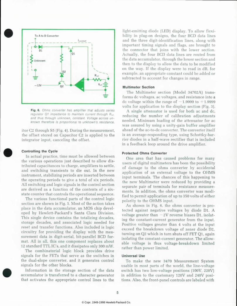
F i g . 6 . O h m s c o n v e r t e r h a s a m p l i f i e r t h a t a d j u s t s s e r i e s r e g u l a t o r 0 7 i m p e d a n c e t o m a i n t a i n c u r r e n t t h r o u g h R , , , . a n d t h u s t h r o u g h u n k n o w n , c o n s t a n t . V o l t a g e a c r o s s u n k n o w n t h e r e f o r e i s p r o p o r t i o n a l t o u n k n o w n ' s r e s i s t a n c e .
¡tor C2 through S5 (Fig. 4). During the measurement, the offset stored on Capacitor C2 is applied to the integrator input, canceling the offset.
Control l ing the Cycle In actual practice, time must be allowed between
the various operations just described to allow dis tributed capacitances to charge, amplifiers to settle, and switching transients to die out. In the new instrument, stabilizing periods are inserted between the operating periods to give a total of six periods. All switching and logic signals in the control section are derived as a function of the contents of a six- state counter that controls the operational sequence.
The various functional parts of the control logic section are shown in Fig. 5. Most of the action takes place in the data accumulator, an MOS chip devel oped by Hewlett-Packard's Santa Clara Division. This single device contains the totalizing decades, storage decades, and associated logic needed for reset and transfer functions. Also included is logic circuitry for providing the display with the mea surement data in digit-serial, bit-parallel BCD for mat. All in all, this one component replaces about 12 standard TTL IC's, and it dissipates only 300 mW.
The combinatorial logic block provides drive signals for the FETs that serve as the switches in the dual-slope converter, and it generates control signals for the other blocks.
Information in the storage section of the data accumulator is transferred to a character generator that activates the appropriate control lines to the
light-emitting diode (LED) display. To allow flexi bility in plug-on designs, the four BCD data lines and the three digit-identification lines, along with important timing signals and flags, are brought to the connector that joins with the lower section. Actually, the four BCD data lines are routed from the data accumulator, through the lower section and then to the display to allow the data to be modified on the way. If the display were to read in dB, for example, an appropriate constant could be added or subtracted to account for changes in range.
Mult imeter Sect ion The Multimeter section (Model 34702A) trans
forms dc voltages, ac voltages, and resistance into a dc voltage within the range of —1.9999 to +1.9999 volts for application to the display section (Fig. 3).
A single attenuator is used for both ac and dc, reducing the number of calibration adjustments needed. Minimum loading of the attenuator for ac was assured by using a unity-gain buffer amplifier ahead of the ac-to-dc converter. The converter itself is an average-responding type, using Schottky-bar- rier diodes in a half-wave rectifier that is included in a feedback loop around the drive amplifier.
Protected Ohms Converter One area that has caused problems for many
users of digital multimeters has been the possibility of damage to the ohms converter by accidental application of an external voltage to the OHMS input terminals. The chances of this happening to the new Multimeter were reduced by providing a separate pair of terminals for resistance measure ments. In addition, the ohms converter was modi fied to permit application of up to 350 volts of either polarity to the OHMS input.
As shown in Fig. 6, the ohms converter is pro tected against negative voltages by diode Dl. A voltage greater than —2V reverse biases Dl, isolat ing the constant-current generator from the input. Positive voltages greater than 4 volts at the input exceed the breakdown voltage of zener diode D2, turning on Q2 which in turn shuts off FET Ql, again isolating the constant-current generator. The allow able voltage is thus voltage-breakdown limited rather than power limited.
Universal Use To make the new 3470 Measurement System
usable in most parts of the world, the line-voltage switch has two low-voltage positions (100V, 220V) in addition to the customary 120V and 240V posi tions. Also, the front-panel controls are labeled with
© Copr. 1949-1998 Hewlett-Packard Co.

internationally agreed upon symbols. Wherever the instrument may be, a wired-in
jumper in the display section can be clipped to a test point to give a quick check of the display and control logic performance (should read ' — 10000' with lower section attached).
Acknowledgments Many thanks are due the following for their tech nical contributions and also for their contributions to this article: Greg Boxleiter, digital design; Jim Eller, ohmmeter circuits; Art Dumont, ac converter; Eugene Packer, power supplies and battery and BCD modules; and Gary Peterson, product design. Many thanks are also due Al Boswell and John Hettrick for their help in getting the instrument into pro duction, and to Bill Kay for guidance and counsel. S
References 1. I. T. Band, H. J. Jekat, E. E. May, "Lilliputian Measur ing System Does Much, Costs Little," Hewlett-Packard Journal, August 1969. 2. "Low-Speed 'Chopping' Improves Digital Voltmeter Accuracy," Electrical Design News, August 1959.
Albert Gookin
Fresh out of the Universi ty of Cal i fornia at Berkeley wi th a BSEE degree, A l Gookin jo ined the HP Loveland (Colorado) Div is ion in 1 965, going r ight to work wi th the team deve lop ing the Model 3460A Dig i ta l Vo l tmeter . A l cont inued on wi th the Models 3461 A and 3462A and he a lso worked on the 3450A Dig i ta l Mul t imeter and 3403A True- rms Vo l tmeter be fore assuming pro jec t leadersh ip fo r the 3470 Measurement System. A long the way, he earned h is MSEE at Colorado State Univers i ty in the HP Honors Cooperat ive Program.
Al 's outs ide in terest range f rom stamp and co in co l l ec t i ng to mo to rcyc l i ng and l andscap ing .
S P E C I F I C A T I O N S H P M o d e l 3 4 7 0 M e a s u r e m e n t S y s t e m
( 3 4 7 4 0 A D i s p l a y w i t h 3 4 7 0 2 A M u l t i m e t e r s e c t i o n )
A C a n d D C V O L T A G E F U L L R A N G E D I S P L A Y ; Â ± 1 . 0 0 0 0 V Â ± 1 0 0 . 0 0 V
 ± 1 0 0 0 0 V  ± 1 0 0 0 0 V . O V E R R A N G E : 1 0 0 0 V R a n g e : 2 0 % .
A H o t h e r r a n g e s : 1 0 0 % ( 1 9 9 9 9 m a n r e a d i n g ) .
I N P U T T E R M I N A L S : F l o a t i n g p a i r .
1 0 0 a n d 1 0 0 0 V r a n g e s : 1 0 . 1 M ' . J : r 0 . 1 % , 6 5 p F m a x . M A X I M U M I N P U T V O L T A G E :
H i g h t o L o w : Â ± 1 2 0 0 V d c o r r m s e x c e p t o n 1 V a c t h e r e i s 2 . 5 x 1 0 " ' V - H z l i m i t w i t h m i n i m u m o f 3 0 0
L o * t o c h a s s i s : Â ± 5 0 0 V .
3 4 7 4 0 A D I S P L A Y w i t h 3 4 7 0 1 A D C V O L T M E T E R
cept : I N P U T R E S I S T A N C E ; 1 0 M i ; Â ± 0 1 % o n a l l r a n g e s .
G E N E R A L P O W E R : 1 0 0 / 1 2 0 / 2 2 0 / 2 4 0 V - 1 0 % , + 5 % s w i t c h a b l e ; 4 8 H z t o 4 4 0
8 . 7 V A . O p n 0 5 0 : M e a s u r e m e n t i n t e g r a t i o n i n t e r v a l o p t i m i z e d f o r m a x i -
n r e j e c t i o n o f 5 0 H z i n t e r f e r e n c e o n s i g n a l . O p n 0 6 0 . M e a s u r e m e n t m t e g r a l i o n i n t e r v a l o p t i m i z e d t o r 6 0 H z
W E I G H T : 3 4 7 4 0 A D i s p l a y . 3 I b ( 1 . 3 5 k g ) 3 4 7 0 1 A D C V o l t m e t e r . 2 I b [ 0 , 9 0 k g ] 3 4 7 0 2 A M u l t i m e t e r 2 I b ( 0 , 9 0 k g )
3 4 7 2 1 A B C D M o d u l e : 1 ' z I b ( 0 , 6 7 k g | P R I C E S ( d o m e s t i c U S A o n l y ) :
D C V O L T A G E O N L Y A C C U R A C Y ( 3 0 d a y s , + 2 3 Â ° C Â ± 5 Â ° C , ^ 9 5 % R H ) : Â ± ( 0 . 0 3 % c
+ 0 0 1 % o f r a n g e ) . E F F E C T I V E C O M M O N M O D E R E J E C T I O N ( 1 k ' . " . 1 u n b a l a n c e
D C : > 8 0 d B . 5 0 H z ( O p t i o n 0 5 0 ) : > 1 2 0 d B ( 5 0 H z  ± 0 . 1 % ) . 6 0 H z ( O p t i o n 0 6 0 ) : > 1 2 0 d B ( 6 0 H z  ± 0 . 1 % ) -
O I M E S I O N S : !
" O p t i o n 0 5 0 . 5 0 H z o p e r a t i o n , n o c h a r g e ' O p t i o n 0 6 0 , 6 0 H z o p e r a t i o n , n o c h a r g e 3 4 7 0 1 A D C V o l t m e t e r , $ 1 5 0 3 4 7 2 0 A B a t t e r y M o d u l e , $ 2 0 0 3 4 7 0 2 A M u l t i m e t e r , $ 2 7 5 3 4 7 2 1 A B C D M o d u l e , $ 1 7 5 .
M A N U F A C T U R I N G D I V I S I O N : L O V E L A N D D I V I S I O N 8 1 5 F o u r t e e n t h S t r e e t , S . W . L o v e l a n d , C o l o r a d o 8 0 5 3 7
MON 5 0 H z ( O p t i o n 0 5 0 ) : > 6 0 d B ( 5 0 H z  ± 0 . 1 % ) . 6 0 H z ( O p t i o n 0 6 0 ) : > 6 0 d B ( 6 0 H z  ± 0 . 1 % ) .
R E A D I N G R A T E : O p t i o n 0 5 0 , B / s , f i x e d : O p t i o n 0 6 0 . 5 / s , f i x e d .
F R E Q U E N C Y R A N G E : 4 5 H z t o 1 0 0 k H z I N P U T C O U P L I N G : a c . m a x d c b l o c k i n g o f  ± 6 0 0 V . A C C U R A C Y ( 3 0 d a y s , + 2 3 C * 5 " C > 9 5 % H H ) :
4 5 H z t o 2 0 k H z . - ( 0 2 5 % o f r e a d i n g + 0 0 5 % o f r a n g e ) 2 0 k H z l o 1 0 0 k H z : - ( 0 . 7 5 % o f r e a d i n g + 0 . 0 5 % o f r a n g e ! .
E F F E C T I V E C O M M O N M O D E R E J E C T I O N ( 1 k ' . . ' u n b a l a n c e ) . 5 0 H i ( O p t i o n 0 5 0 ) : > 6 0 d B ( 5 0 H z  ± 0 . 1 % ) ; 6 0 H z ( O p t i o n 0 6 0 1 > 6 0 d B ( 6 0 H z  ± 0 . 1 % )
R E S P O N S E T I M E : - 2 s w i t h i n  ± 0 3 % o f f i n a l v a l u e o r 2 0 c w h i c h e v e r i s g r e a t e r .
O H M S F U L L - R A N G E D I S P L A Y : 1 0 0 . 0 0 2 1 0 0 0 0 k ' . . '
1 O O O O k ' J 1 . 0 0 0 0 M L J 1 0 0 0 0 k i l 1 0 0 0 0 M ' . . '
A C C U R A C Y ( 3 0 d a y s , + 2 3 = 0 Â ± 5 Â ° C . < 9 5 % R H ) : 1 0 M l . ' r a n g e : ~ ( 0 . 2 5 % o f r e a d . n g + 0 . 0 2 % o f r a n g e ] . - - - - - - : i % o f r e a d i n g + 0 0 2 % o f r a n g e ) .
I N P U T T E R M I N A L S : F l o a t i n g p a . r ( d i f f e r e n t f r o m v o l t a g e n p C U R R E N T T H R O U G H U N K N O W N : 1 0 m A o n 1 0 0 ' . ' . r a n g e d e
© Copr. 1949-1998 Hewlett-Packard Co.

A New Five-Digi t Mult imeter That Can Test I tself Along wi th 5-digi t resolut ion, guarded inputs, and other at tr ibutes of a precis ion mult imeter, th is one has an enhanced conf idence factor : i t can Interrogate itself to verify that all goes well.
By Lee Thompson
INSTRUMENTS WITH SOME THINKING' CAPABILITY — e.g., voltmeters that decide for
themselves what range they should be on, counters with variable time bases that 'calculate' quantities like rpm from measurements of frequency — have been with us for some time. With the advent of low- cost solid-state memories and large-scale integrated circuits, however, really high-powered 'thinking' capability can now be built at low cost into all types of instruments.
Recently described in these pages were two fre quency synthesizers that use digital processors with programs stored in read-only memories (ROMs). With just a few commands from the calculator-like keyboards, these instruments calculate and generate whole series of accurately-known frequencies.1 L
Then, of course, there is the HP Model 5360A Computing Counter, a pioneering 'intelligent' instru ment introduced three years ago that not only uses stored programs to control measurements, but which also performs sophisticated calculations on the measurement data, giving highly accurate infor mation in an instant.3
Now another capability of digital processor con trol emerges. Described in this article is a new Digital Multimeter (Model 3490A) that is capable of testing itself. A significant point about the self- test capability is that it was added to the instru ment without increasing the cost — the initial design already included a digital processor for instrument control, so the self-test capability could be included merely by adding programs to those already stored in ROM.
Why self-test? Because it adds a major confidence factor. As any experienced engineer is painfully aware, there are times when measurements come
out all wrong, but the source of the problem is far from obvious. Is it really the unit under test, or is it a power supply some place? — or a signal source? — or could it be the voltmeter? Self-test eliminates the voltmeter as the offender and gives the engineer confidence in using it for testing the rest of the system.
Self-test also simplifies programs for automatic systems. Just two instructions can program the voltmeter to check itself and indicate its readiness to make a measurement. The self-test capability also saves considerable time in the repair and calibration lab.
The 3490A The instrument in which this self-test capability
is found is a 5-digit, autoranging, fully-guarded, integrating Multimeter with a very modest price (Fig. I). The most sensitive dc range is 100 mV full scale, giving the instrument 1 fiV resolution. Accu racy is better than 0.01% of reading and the volt meter overranges to 20% above full scale on all ranges except the lOOU-volt range. The input is fully protected against excessive voltages, with standing 1000 volts on all ranges including the 100 millivolt range. The instrument can make five read ings per second and when autoranging to another voltage range, it switches at a five-per-second rate.
The new Multimeter also measures resistance by the four-wire technique in 6 ranges from 100 Q full scale to 10 MQ, and it measures ac voltages in four full-scale ranges from 1 to 1000 volts. Frequency range is 20 Hz to 100 kHz on the 100 and 1000 V ranges and 20 Hz to 250 kHz on the 1 and 10 V ranges.
Useful options increase the instrument's range of
© Copr. 1949-1998 Hewlett-Packard Co.

Fig . 1 . Mode l 3490 A D ig i ta l Mu l t i m e t e r m e a s u r e s d c v o l t s , a c vo l ts and res is tance wi th 10 ppm r e s o l u t i o n . M o d e l s h o w n h e r e has Ra t i o and Samp le -and -Ho ld o p t i o n s i n s t a l l e d . E a s y - t o - d e c i - p h e r r a n g e a n d f u n c t i o n c o n t r o l b r i n g s i n t o v i e w o n l y t h o s e r a n g e s n e e d e d f o r f u n c t i o n s e l e c t e d . D e p r e s s i n g a p p r o p r i a t e tab se lects range des i red. S l ide- o u t i n s t r u c t i o n c a r d i n c l u d e s o p e r a t o r i n s t r u c t i o n s f o r u s i n g Mul t imeter to test i tse l f .
capabilities. One is sample-and-hold. This option makes it possible to make exact measurements at selected points on changing voltages, such as mea suring peak amplitudes or determining amplifier settling times. Another option is ratio measure ments, both dc/dc and ac/dc. Yet other options include remote control by either standard BCD in puts or by the new 'party-line' programming that allows the instrument to operate in parallel with other instruments on only 12 programming lines. Both remote control options have fully isolated digital inputs.
Self -Test ing How can a voltmeter check itself? In the 3490A,
the quickest test is one that causes the instrument to read its own internal positive reference voltage using the negative reference voltage as the measure ment reference. The measurement automatically re peats with the roles of the reference voltages inter changed. This gives a quick indication that the voltmeter is indeed ready to make measurements. This test also discloses any voltage level difference between the reference sources.
Another test actually is a series of 10 tests that the voltmeter steps through automatically. When this test is initiated, the instrument autoranges one step for each reading, up through all ranges and then back down again. During each step, the data counters are permitted to count for periods of time that differ for each range. The operator can com pare the resulting readings with a list on a pull-out instruction card attached to the underside of the instrument. If the series of readings agree with the card, the operator can be sure that the display, ranging and counting circuits, and at least 70% of the logic, are all functioning correctly.
Other tests, more useful for troubleshooting and calibration, check the calibrations of the input at tenuator and amplifier and check for amplifier offsets in various parts of the instrument. The tests
can be used in combinations to isolate problems to one particular area of the instrument. The tests also make it possible to verify calibration of all de-voltage ranges with only two voltage standards
State B
H ^
Issue Al l C o m m a n d s i n
P r e p a r a t i o n f o r a R e a d i n g
- Y e s - H a s
T r i g g e r B e e n Rece ived?
Issue Al l C o m m a n d s N o t
R e l a t e d t o T e s t
Go to O t h e r T e s t s D e p e n d i n g o n R a n g e
f G e n e r a t e J D e l a y s f o r
| O H M s , A C , I e t c .
Yes T S t a t e D
Begin U p - R a m p
o f I n t e g r a t o r
S t a r t C o u n t i n g
- N o
No—
{Comple te Read ing a n d R e t u r n t o
Look fo r a N e w T r i g g e r
D isp lay a n d
U p R a n g e
R e t u r n t o S t a t e A ( T u r n - O n )
Fig. 2 . Typ ica l f low char t used in a lgor i thmic s ta te machine l og i c des ign i l l us t ra tes how add i t i ona l capab i l i t i es can be a d d e d t o i n s t r u m e n t t h a t h a s d i g i t a l p r o c e s s o r . S e l f - t e s t c a p a b i l i t y w a s i n c l u d e d i n n e w M u l t i m e t e r b y i n s e r t i n g t es t qua l i f i e r ( second d i amond f r om t op ) i n no rma l i n s t r u ment rou t ine and then add ing tes t p rograms.
© Copr. 1949-1998 Hewlett-Packard Co.

Hi F ig . 3 . S imp l i f i ed b lock d iag ram o f Mode l 3490A Mu l t imete r in i t s bas ic conf igurat ion. Input s igna ls g o d i r e c t l y i n t o g u a r d ( m e t a l s h i e l d t h a t e l e c t r i c a l l y i s o l a t e s c i r cu i t s t rom power l i ne to avo id g r o u n d l o o p s a n d g i v e 1 4 0 - d B s u p p r e s s i o n o f c o m m o n - m o d e s i g n a l s ) . D i g i t a l i n f o r m a t i o n t o a n d f r o m e x t e r n a l e q u i p m e n t i s c o u p l e d i n t o a n d o u t o f g u a r d b y l i g h t - c o u p l e d i s o l a t o r s ( n o t shown).
(1 and 10 V), thereby reducing the number of verifi cation standards needed to support the instrument.
An Algori thmic State Machine The digital controller that performs all these tests,
as well as controlling normal operation of the Multi meter, is a read-only-memory-driven sequential ma chine. Procedures or algorithms that the controller executes for measuring and testing can be described by flow charts, one of which is shown in Fig. 2. The rectangular boxes contain machine operations executed during specific time intervals known as machine states with the sequence of operations de termined by the diamond-shaped decision boxes. At the completion of each state time, the controller advances to the next state indicated.
The design of the controller is based on a set of procedures known as Algorithmic State Machine Logic design, developed at the HP Laboratories in Palo Alto. One of the advantages of this technique is that a flow chart can be converted to a reliable hardware design that in turn can be translated di rectly into a ROM design. This approach leads to microprogrammed machines with completely speci fied behavior. Special features, such as self-test, are easily worked into the program without requiring additional hardware.
How i t measures A block diagram of the new Model 3490A Multi
meter in its basic configuration is shown in Fig. 3. It uses the dual-slope technique to convert a dc volt age into digital information with circuits that oper ate in much the same way as the 3470 Measurement System, described in the article beginning on page 2.
As does the Model 3470, the 3490A Multimeter uses autozero circuits, a slope amplifier, and feed forward offset to compensate for slope amplifier
delay ( Fig. 4, page 4 ). Additional refinements are needed, however, to insure the stability and noise immunity needed for 5-digit resolution. The integrator in the voltage-to-time converter, for in stance, operates over a ±18-volt span which, with the X20 slope amplifier, gives a slope of 3.6 mV per clock pulse, making it possible for the comparator to sense zero crossover closely enough to give a readout resolution of 10 ppm. Actually, the inte grator can go to approximately 22 volts, about the limit possible with commonly-used 1C op amps, allowing 20% overranging.
Any noise or switching transients on the signal could also affect the instant of zero-crossover de tection. Transients appearing at the integrator sum ming junction would be coupled to the slope ampli fier by the integrating capacitor itself. This noise is eliminated by tapping off the signal at the integrator summing junction and feeding it through a resistor network to the opposite-polarity input of the slope amplifier. Since both inputs to the slope amplifier then move in the same direction in response to a transient, the transient will not appear at the ampli fier's output.
Laser-Tr immed Gain An input amplifier scales the input voltage to a
range of ±10 volts for the integrator input. This is a FET input, high-gain, low-noise, hybrid integrated circuit amplifier that gives the instrument an input impedance of greater than 1010 ohms on the 0.1, 1, and 10 V ranges (the passive attenuator used on the 100 and 1000 V ranges gives an input impedance of 10 MO).
The amplifier has a switched resistive feedback network to give selectable gains of XI, X10, and X100. Switching is performed by FETs, mounted directly on the substrate. The resistors are thin
© Copr. 1949-1998 Hewlett-Packard Co.

films deposited on the substrate and trimmed with a computer-controlled laser beam to a high degree of accuracy. The substrate is sealed with a metal cover to maintain the high input impedance over a wide range of humidities. Because of the close prox imity of all the circuits on the substrate, thermal differences and the resulting thermal emf's are re duced significantly.
AC Conver te r The ac converter is an average-responding type
calibrated to display the rms value of a sine-wave input. It uses the traditional half-wave rectifier en closed in a feedback loop.
A block diagram is shown in Fig. 4. Ranging is provided by a passive input attenuator, switched in on the 100- and 1000-volt ranges, and a switched feedback network in the buffer amplifier that changes amplifier gain by a factor of 10. By using only one amplifier for both buffering and attenua tion, the interaction of two separate amplifiers with attenuation is avoided, permitting an accuracy spec ification that is constant over the frequency range from 50 Hz to 100 kHz. The buffer amplifier (Al) is a wideband monolithic op amp that minimizes parasitic capacitance, extending the bandwidth on the 1- and 10-volt ranges to 250 kHz.
The output filter is a four-pole active filter opti mized to allow the low end of the frequency range to be reduced to 20 Hz (50 Hz has commonly been the lower limit) while maintaining a one-per-second reading rate.
Ohms Conver ter The ohms converter supplies a constant current
to an unknown resistance through the front-panel n SIGNAL terminals. The resulting IR drop across the unknown is then determined through connec tions made to the front-panel INPUT terminals. Separation of the voltage-carrying leads from the current-carrying leads removes the possibility of degrading the measurement with the IR drops de veloped across the current-carrying leads (RLi and RL2 in Fig. 5). It is thus practical to include a 100 O range with its 1-milliohm resolution.
Resistance measurements are actually performed as ratio measurements, with the instrument deter mining the ratio of the unknown resistance to a known resistance inside the instrument. As shown in the diagram of Fig. 5, the same current (Ix) flows through the unknown (R,) and the reference (R,er). The ratio of the IR drops across these resistances is thus the same as the ratio of the resistances. As a result, I* does not have to be known precisely.
The instrument's voltage-to-time converter re sponds to the voltage across the unknown during the up-ramp (Tl in the timing diagram in Fig. 4 , page 4 ) and to the voltage across the reference during the down ramp (T2). With Tl set at 100,000 clock counts, and R,et scaled to be equivalent to the full-scale value, the count obtained during T2 can be displayed as the unknown resistance, with ap propriate placement of the decimal point.
The n SIGNAL terminals are fully protected against accidental application of voltages up to 250 volts rms continuously, and fuse-protected up to 1000 volts (see Fig. 5).
Sample and Hold The sample-and-hold option makes it possible to
' A v a i l a b l e f a l l 1 9 7 2
100 V 1000 V
P a s s i v e A t t e n u a t o r
F i g . 4 . A c - t o - d c c o n v e r t e r c o m b i n e s a t t e n u a t i o n a n d b u f f e r i n g f u n c t i o n t o g a i n 0 . 1 % a c c u r a c y o v e r w i d e r f r e q u e n c y r a n g e ( 5 0 H z t o 1 0 0 k H z ) . A m p l i f i e r A 2 s t a b i l i z e s d c l e v e l o f A l s o n o z e r o a d j u s t m e n t i s n e e d e d . A s has been common p rac t i ce , two d i o d e s a r e i n c i r c u i t t o m a k e feedback ef fect ive over complete c y c l e o f a c w a v e f o r m , a l t h o u g h o n l y o n e d i o d e i s n e e d e d f o r s ignal rect i f ica t ion.
10
© Copr. 1949-1998 Hewlett-Packard Co.

Ohms Reference to
Measuring Circuit
â € ¢ *
Floating Power
Supplies
To I N P U T M e a s u r i n g
i C i r c u i t
â € ” O *
F ig . 5 . Ohms conver te r supp l ies c o n s t a n t c u r r e n t t h r o u g h S I G N A L t e r m i n a l s t o u n k n o w n r e s is tance R, . Inst rument measures v o l t a g e d r o p a c r o s s f l , t h r o u g h INPUT te rm ina l s , exc lud ing vo l t a g e d r o p s i n c u r r e n t - c a r r y i n g l e a d s f l u a n d f l u . I n s t r u m e n t compares vo l tage drop across f l , t o vo l t age d rop ac ross s tanda rd res i s to r f l , . ( . Gas - f i l l ed tube l im i t s vo l tage app l ied to c i r cu i t s by f i r i n g w h e n e v e r e x c e s s i v e v o l t a g e i s a p p l i e d a c c i d e n t a l l y t o O h m s t e r m i n a l s d u r i n g r e s i s t a n c e m e a s u r e m e n t s . V o l t a g e h igher than 250 vol ts b lows fuse.
measure a changing voltage at a particular instant in time, rather than integrating the voltage over the measurement interval.
Design criteria were fast acquisition of the signal but no appreciable sag during the measurement in terval. Hence, sample and hold is performed in two steps, as shown in Fig. 6. The first sample-and-hold amplifier stores the input on a capacitor (Cl) that is small enough to respond quickly to changes in the input voltage. The second amplifier has a larger ca pacitor (C2) that retains a sampled voltage without appreciable sag during the measurement interval.
When operating in the "Track-and-Hold" mode, the system is connected continuously to the input by way of switches Si, S2, and S3. At the instant a trigger is received, the Logic Controller opens S2, retaining the instantaneous signal voltage on capaci tor Cl. S3 remains closed for an additional 2 ms, allowing the charge on C2 to reach the same level as Cl. S3 then opens and C2 holds the charge while
a measurement of its voltage is made. This mode is useful for continuously tracking and measuring sig nals with small perturbations (less than 10% of full- scale).
For large changes, such as measuring the top of a full-scale voltage step, the instrument is operated in the "Acquire-and-Hold" mode. This mode inserts a delay between the trigger and the opening of S2 (e.g., 256 ¡j.s on the 1 V range ), allowing the input amplifier to stabilize to within rated accuracy at the new voltage level before S2 is opened.
The voltage retained on a third holding capacitor (C3) drives an output for monitoring the waveform as sampled. A third holding capacitor is required be cause in practice, the reference voltage is switched through the sample-and-hold amplifier on the down- ramp phase of the measurement. S4 remains open during this time so the reference voltage will not appear on the output.
An oscilloscope can be helpful when measure-
To Measur ing
Circuits
AC-Coupled Tr igger
Analog Output
Main Instrument Controller
F ig . 6 . Samp le -and -ho ld re ta ins instantaneous value of input level on capac i to r C1 when sw i t ch S2 o p e n s . S w i t c h S 3 o p e n s 2 m s l a t e r , g i v i n g t i m e f o r C 2 t o c h a r g e t o s a m e v o l t a g e a s C l . I ns t rumen t measu res vo l t age re ta ined on C2.
11
© Copr. 1949-1998 Hewlett-Packard Co.

ments are made at points along a repetitive wave form. The delayed-sweep trigger of the oscilloscope
can be used as a sample-and-hold trigger. The de layed-sweep intensity dot can then be moved along the waveform to select the sampling points.
A c k n o w l e d g m e n t s The original self-test algorithm was conceived by
David Palermo, who designed the logic controller. John McDermid was responsible for the input am plifier, including development of the hybrid switch ing network, and the analog-to-digital converter. Larry Bower had responsibility for the ohms con verter and the power supplies, as well as providing timely suggestions in other design areas. David Crook was responsible for both the analog and dig ital designs in the sample-and-hold. Arnold Joslin was involved in the initial phases of the product design, which was completed by Michael Williams. Robert Livingood is currently designing the "party- line" remote control option.
Special thanks are due Bill Rothmeyer and Skip Beatty for their help in building and testing proto types. John Hettrick was particularly helpful dur ing the transition to production. Also, special thanks are due William Kay for his guidance and timely inputs during the entire development program. S
References 1. J. C. Shanahan, "Uniting Signal Generation and Signal Synthesis," Hewlett-Packard Journal, Dec. 1971. 2. C. A. Kingsford-Smith, "The Incremental Sweep Gen erator — Point-by-Point Accuracy with Swept-Frequency
Convenience," Hewlett-Packard Journal, July 1972. 3. G. B. Gordon and G. A. Reeser, "Introducing the Com puting Counter," Hewlett-Packard Journal, May 1969.
L e e T h o m p s o n
Lee Thompson s tar ted wi th HP as product des igner in 1966, cont r ibu t ing the product des ign and some c i rcu i t des igns to the t rue- rms conver ter in the Model 3450A Dig i ta l Mul t imeter . He a lso designed the ampl i f ier for the t rue- rms conver ter in the Model 3480A Dig i ta l Mul t imeter before becoming pro jec t leader for the 3490A Dig i ta l Mul t imeter.
Lee earned his BSEE degree at the Univers i ty of Texas at Aust in (1 966) and an MSEE degree at Colorado State Univers i ty in the HP Honors Cooperat ive Program. He's a member of Tau Beta Pi . Outs ide of work ing hours, he p lays gol f and enjoys the usual Colorado at t ract ions (h ik ing, mounta in c l imbing, e tc . ) but he a lso devotes much t ime to youth act iv i t ies, being inst rumenta l in set t ing up a l oca l d rug -abuse cen te r .
D C V O L T A G E F U L L R A N G E D I S P L A Y : = 1 0 0 0 0 0 V ~ 1 0 0 0 0 0 V
 ± 1 0 0 0 0 0 V  ± 1 0 0 0 0 0 V  ± 1 0 0 0 0 0 V
O V E R R A N G E : 2 0 % o n a l l r a n g e s e x c e p t 1 0 0 0 V r a n g e R A N G E S E L E C T I O N : m a n u a l , a u t o m a t i c , o r r e m o t e ( o p t i o n a l ) . A C C U R A C Y 9 0 d a y s + 2 3 C C ^ 5 * C )
0 T V r a n g e = ( 0 0 1 % o l r e a d i n g + 0 0 0 5 % o f r a n g e l . 1 V t o 1 0 0 0 V r a n g e : Â ± { 0 0 1 % o f r e a d i n g + 0 0 0 2 % o f r a n g e ) . N o t e s : O n 1 0 0 0 V r a n g e , a d d 0 0 4 p p m / v o l t t o % o f r e a d i n g s p e c i - l i c a t i o n T h e r m a l E M F s g e n e r a t e d e x t e r n a l l y m a y b e c o m p e n s a t e d b y u s i n g r e a r - p a n e l z e r o a d j u s t
T E M P E R A T U R E C O E F F I C I E N T 0 : C t o S O ' C 0 1 V r a n g e * ( 0 0 0 1 % o f r e a d i n g + 0 0 0 0 7 % o f r a r t g e t / ' C . 1 V t o 1 0 0 0 V r a n g e  ± 1 0 0 0 1 % o f r e a d i n g + 0 0 0 0 3 % o f ' a n g e C
I N P U T : F u l l y g u a r d e d w i t h 1 4 0 0 8 E C M R a t d c a n d 6 0 H z = 0 - Â ° = w i t h 1 * ' . . ' i m b a l a n c e b e t w e e n G u a r d a n d L o w
M A X I M U M I N P U T V O L T A G E : H i g h t o L o w . Â ± 1 5 0 0 V p e a k o n a l l r a n g e s . G u a r d t o C h a s s i s . Â ± 5 0 0 V p e a k : G u a r d 1 0 L o w . Â ± 2 0 0 V p e a k
I N P U T R E S I S T A N C E : 0 1 V t o 1 0 V r a n g e s : > 2 Â ± 1 0 " 1 1 . 1 0 0 V a n d 1 0 0 0 V r a n g e s 1 0 M G Â ± . 0 . 1 5 % .
M A X I M U M R E A D I N G R A T E : 5 r e a d i n g * / Â » N O R T I C
O p t i o n 0 5 0 > 5 0 d B a l 5 0 H z  ± 0 1 % O p t i o n 0 6 0 : > 5 0 d S a t 6 0 H z  ± 0 1 %
A C V O L T A G E F U L L R A N G E D I S P L A Y : 1 0 0 0 0 0 V 1 0 0 0 0 0 V
1 0 0 0 0 0 V 1 0 0 0 0 0 V O V E R R A N G E : 2 0 % o n a l l r a n g e s e x c e p t 1 0 0 0 V r a n g e R A N G E S E L E C T I O N : m a n u a l , a u t o m a t i c , o r r e m o t e ( o p t i o n a l ) . A C C U R A C Y ( 9 0 d a y s . + 2 3 ' C Â ± 5 ' C )
2 0 H z - 5 0 H z  ± ( 0 2 5 % o f r e a d i n g + 0 0 5 % o f r a n g e ) 5 0 H z - l O O k H z :  ± 1 0 1 % o f r e a d i n g + 0 0 2 5 % o f r a n g e ) . t O O k H z - 2 5 0 k H z ( I V a n d 1 0 V r a n g e s o n l y
 ± ( 0 7 5 % o f r e a d i n g + 0 0 6 % o f r a n g e ) N o t e s : G u a r d m u s t b e c o n n e c t e d t o L o w O n 1 0 0 0 V r a n g e , a d d
S P E C I F I C A T I O N S H P M o d e l 3 4 9 0 A D i g i t a l M u l t i m e t e r
0 . 0 1 p p m / ( v o i t - k H z ) . S p e c i f i c a t i o n s a r e f o r i n p u t l a v à © i s a b o v e 1 / l O O t h o f f u l l s c a l e .
T E M P E R A T U R E C O E F F I C I E N T ( 0  ° C t o 5 0  ° C t  ± ( 0 0 0 2 % o f r e a d i n g + 0 0 0 1 % o f r a n g e ) /  ° C .
I N P U T I M P E D A N C E : 2 M Ã 3 Â ± 1 % s h u n t e d b y < 6 5 p F ( < 9 Q p F w i t h
M A X I M U M R E A D I N G R A T E : 1 r e a d m g / s . R E S P O N S E T I M E : < I s t o w i t h i n r a t e d a c c u r a c y f o r s t e p i n p u t a p
p l i e d c o i n c ' d e n l w i t h e n c o d e t r i g g e r M A X I M U M I N P U T V O L T A G E : 1 0 0 0 V c m s ; = 1 5 0 0 V p e a k
O H M S F U L L R A N G E D I S P L A Y : 1 0 0 0 0 0 k ' . . > 1 0 0 0 0 0 k Q
1 00000 k ' . . ' 1000 00 k i . > l O O O O O k ' J 1 0 0 0 0 0 k i . '
O V E R R A N G E : 2 0 Â ° e o n a l l r a n g e s R A N G E S E L E C T I O N : m a n u a l , a u t o m a t i c , o r r e m o t e ( o p t i o n a l ! A C C U R A C Y ( 9 0 d a y s , 2 3 C C Â ± 5 ' C ) :
0 1 k i . ' r a n g e :  ± ( 0 0 1 2 % o f r e a d i n g + 0 0 0 5 % o f r a n g e ) . 1 - 1 0 0 k 1 . . 1 r a n g e s :  ± ( 0 . 0 1 2 % o f r e a d i n g + 0 0 0 2 % o f r a n g e ) 1 0 0 0 k ! ; r a n g e :  ± ( 0 0 1 5 % o f r e a d i n g + 0 0 0 2 % o f r a n g e ) 1 0 . 0 0 0 k ' . : r a n g e  ± ( 0 0 3 5 % o f r e a d i n g + 0 0 0 2 % o f r a n g e )
T E M P E R A T U R E C O E F F I C I E N T ( 0 = C t o 5 0 D C ) : 0 1 k ' . . ' r a n g e . Â ± ( 0 0 0 1 % o f r e a d i n g + 0 0 0 0 7 % o f r a n g e l / 5 C 1 t o 1 0 . 0 0 0 k ' . . ' r a n g e s : Â ± ( 0 0 0 1 % o f r e a d i n g + 0 0 0 0 3 % o f
M A X I M U M V O L T A G E G E N E R A T E D A C R O S S U N K N O W N : 2 0 V f o r o v e r l o a d : 1 3 V f o r v a l i d r e a d i n g
C U R R E N T T H R O U G H U N K N O W N : O T t o 1 0 k ' . ; r a n g e s : r 1 m A 1 0 0 t o 1 0 0 0 k i : r a n g e s = 1 0 - A . 10 .000 k ' J range : = 1 »A .
O V E R L O A D P R O T E C T I O N : N o n - d e s t r u c t i v e t o 2 5 0 V r m s ; F u s e - d e s t r u c t i v e t o  ± 1 0 0 0 V p e a k
M A X I M U M R E A D I N G R A T E : 0 1 t o 1 0 0 k ' . . ' r a n g e s 5 r e a d i n g s ' ! 1 0 0 0 k ' . : r a n g e 4 r e a d i n g s ' * 1 0 , 0 0 0 k i : r a n g e 2 r e a d i n g s s
W A R M - U P T I M E ; o n e h o u r w a r m - u p r e q u i r e d t o m e e t a l l s p e c i f i c a t i o n s o n 0 1 V a n d 0 1 k ' . . ' r a n g e s T h i r t y m i n u t e s w a r m - u p r e q u i r e d l o m e e t a l l o t h e r s p e c i f i c a t i o n s .
H U M I D I T Y R A N G E : - 9 5 Â ° 0 R H , O ' C t o 4 0 ' C D I M E N S I O N S : ' 5 ^ m W x 3 ' i i n H x 1 8 H 0 ( 4 2 5 x 9 8 x 4 6 9 m m ) . W E I G H T : 2 0 ' ! l o s ( 9 , 3 2 k g ) . W h e n r a c k - m o u n t e d , r e q u i r e s s u p p o r t
a t r e a r P O W E R : T O O / 1 2 0 / 2 2 0 / 2 4 0 V + 5 % . - 1 0 % . 4 8 H z t o 4 0 0 H z l i n e
o p e r a t i o n . < 6 0 V A w i t h a l l o p t i o n s O P T I O N S :
O P T I O N 0 5 0 : M e a s u r e m e n t i n t e g r a t i o n i n t e r v a l o p t i m i z e d f o r m a x i m u m r e j e c t i o n o f 5 0 H z i n t e r f e r e n c e o n s i g n a l
O P T I O N H z M e a s u r e m e n t i n t e g r a t i o n i n t e r v a l o p t i m i z e d f o r 6 0 H z o p e r a t i o n
O P T I O N 0 2 0 S y s t e m s e x p a n d : i n c l u d e s r e a r t e r m i n a l s i n p a r a l l e l O P T I O N 0 2 1 : B C D f u l l - p a r a l l e l d a t a o u t p u t : 1 - 2 - 4 - 8 c o d e , e i t h e r
h i g h - t r u e o r l o w - t r u e l o g i c s e l e c t e d b y i n t e r n a l s w i t c h . N e e d s i 0 2 0 .
O P T I O N 0 2 2 : R e m o t e c o n t r o l : 1 - 2 - 4 - 8 Â ¡ o w - t r u e 0 2 0
O P T I O N 0 3 0 d n d e v e l o p m e n t ) : A S C I I - c o d e d r e m o t e c < o u t p u ! d a t a
O P T I O N 0 4 0 : S a m p l e - a n d - h o l d ( a v a i l a b l e f a l l 1 9 7 2 ) O P T I O N 0 6 0 T h r e e - w i r e r a t i o ( a v a i l a b l e f a l l 1 9 7 2 ) .
P R I C E S ( d o m e s t i c U S A o n l y ) 3 4 9 0 A ( i n c l u d e s d c v o l t s , a c v o l t s , a n d o h m s ) S 1 6 5 0 O p t i o n 0 2 0 5 2 0 0 ' O p t i o n 0 5 0 n o c h a r g e O p t i o n 0 2 1 $ 2 5 0 ' O p t i o n 0 6 0 n o C h a r g e O p t i o n 0 2 2 . $ 1 7 5 . O p t i o n 0 8 0 : ( t o b e l e s s t h a n $ 2 5 0 ) O p t i o n 0 4 0 : ( t o b e l e s s t h a n $ 6 5 0 )
M A N U F A C T U R I N G D I V I S I O N : L O V E L A N D D I V I S I O N S 1 5 F o u r t e e n t h S t r e e t , S W L o v e l a n d , C o l o r a d o 8 0 5 3 7
• Must order e i ther opt ion 050 or 060
N e e d s o p t i o n
12
© Copr. 1949-1998 Hewlett-Packard Co.
Functional Modularity Helps Designer and User of New Measurement and Control Subsystem A method of a l locat ing funct ions to modules in a system, funct ional modular i ty g ives a new industr ia l system- in-a-box a h igh degree of versa ti l ity at reasonable cost.
By James M. Kasson
VERSATILITY IS IMPORTANT to both the manufacturer and the user of automatic mea
surement and control systems. The manufacturer must produce systems to satisfy applications rang ing from automobile exhaust emission analysis to nuclear power plant monitoring. Even within a par t i cu la r app l ica t ion , the user ' s needs f requent ly change, and his system should be capable of meet ing these new needs.
The best way to provide the necessary versati l i ty is to make the system modular. However , modular i ty cal ls f o r t r a d e o f f s . I f s m a l l enough modules are used, it may be possible to select the right ones and assemble any thing from an integrated cir cu i t tes te r to a TV se t . Of course, the integration cost wil l be high, because each system is individually engi neered. On the other hand, as more and more circuitry is put into a module, its use becomes more specialized, p roduc t ion vo lume drops , and modu le cos t s s t a r t t o climb.
M a n y t e s t a n d m e a s u r e m e n t s y s t e m s i n t h e p a s t
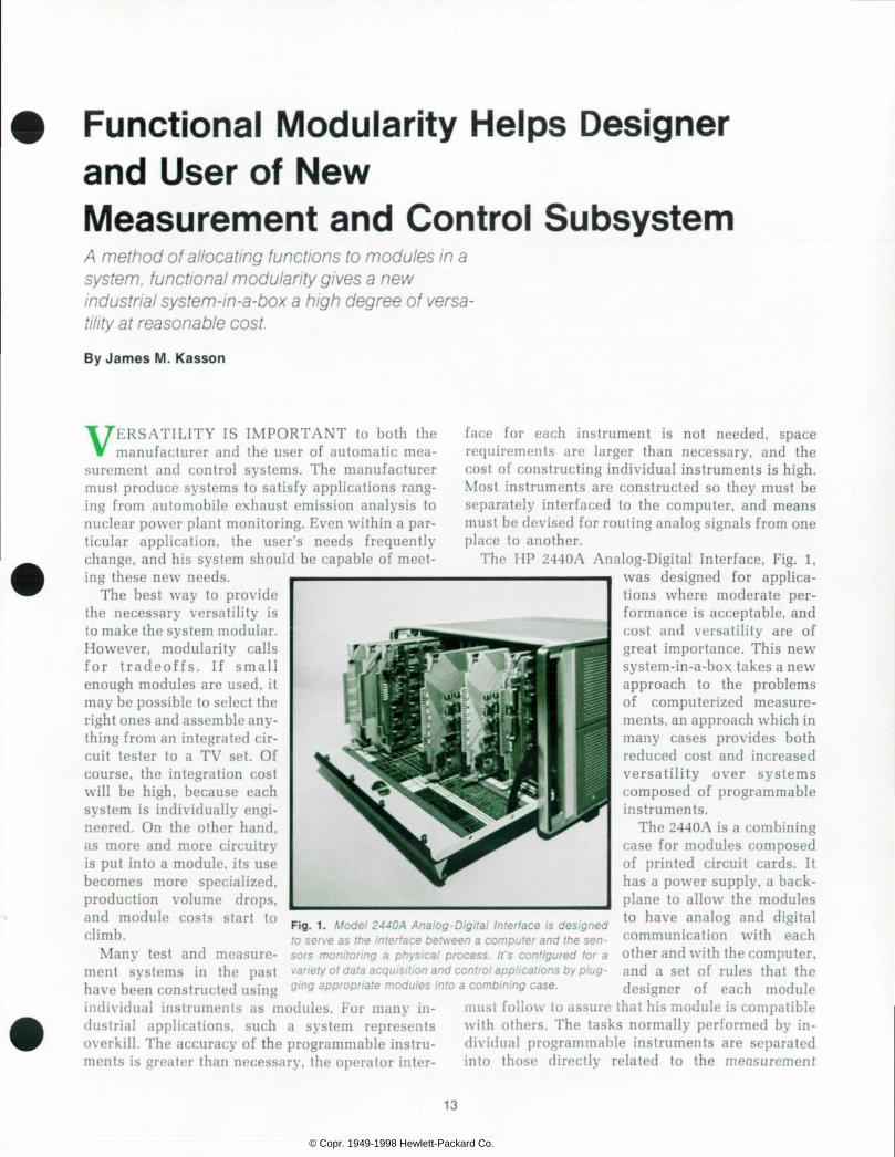
F i g . 1 . M o d e l 2 4 4 0 A A n a l o g - D i g i t a l I n t e r f a c e i s d e s i g n e d to se rve as the in te r face be tween a compute r and the sen s o r s m o n i t o r i n g a p h y s i c a l p r o c e s s . I t ' s c o n f i g u r e d f o r a var ie ty o f data acquis i t ion and cont ro l appl icat ions by p lug-
have combining constructed using 9¡ng appropriate modules into a combining case.
individual instruments as modules. For many in- must fol low to assure that his module is compatible d u s t r i a l i n - s u c h a s y s t e m r e p r e s e n t s w i t h o t h e r s . T h e t a s k s n o r m a l l y p e r f o r m e d b y i n - overkil l . The accuracy of the programmable instru- dividual programmable instruments are separated ments i s g rea te r than necessary , the opera tor in te r - in to those d i rec t ly re la ted to the measurement
f a c e f o r e a c h i n s t r u m e n t i s n o t n e e d e d , s p a c e requi rements a re la rger than necessary , and the cost of constructing individual instruments is high. Most instruments are constructed so they must be separately interfaced to the computer, and means must be devised for routing analog signals from one place to another.
The HP 2440A Analog-Digital Interface, Fig. 1, w a s d e s i g n e d f o r a p p l i c a t i ons whe re mode ra t e pe r formance is acceptable, and cos t and versa t i l i ty a re of great importance. This new system-in-a-box takes a new approach to t he p rob lems o f c o m p u t e r i z e d m e a s u r e ments, an approach which in many cases p rov ides bo th reduced cost and increased v e r s a t i l i t y o v e r s y s t e m s composed of programmable instruments.
The 2440A is a combining case for modules composed of pr inted ci rcui t cards . I t has a power supply, a back plane to allow the modules to have analog and dig i ta l communica t ion wi th each other and with the computer, and a se t o f ru les tha t the d e s i g n e r o f e a c h m o d u l e
13
© Copr. 1949-1998 Hewlett-Packard Co.
function (e.g., input scanner, amplifier, digitizer), and those used to support the measurement function (e.g., operator interface, power supply, mechanical support, digital interface). In the 2440A the direct measurement functions are accomplished on the printed circuit cards while, as far as possible, the support functions are relegated to the combining case, which is designed to serve in a wide variety of applications. The system is configured to a par ticular task by plugging a specific set of functional modules into the case.
System Part i t ioning The measurement system made up of these mod
ules performs some task, which is made up of sev eral functions. As an example, consider a system whose task is to control an assembly line. This task may be divided into the functions of monitoring the line by measuring several voltages, computing corrections, and controlling the line by generating control signals. The functions of measuring volt ages may be further dissected into scanning, signal conditioning, and digitizing.
The partitioning of a system is the assignment of functions to modules. In the assembly-line ex ample, the three main measurement functions may be accomplished in three separate modules, or the voltage-measuring and voltage-generating functions could be combined into one module. The decision as to how much circuitry a module should contain is made by trading off the lower manufacturing cost of large modules with the lower development costs and increased versatility of smaller modules.
The philosophy followed in the 2440A is to par tition the system into the smallest possible mod ules that perform some function that is needed in a large number of systems. If this results in mod ules so small as to have an unreasonable amount of overhead, multiple identical functions are im plemented in one module. This is functional mod ularity.
The result of this kind of partitioning is a col lection of generally useful modules that may be connected together to perform a specific task. Com monly used functions are implemented in separate modules, so each module is useful in many differ ent systems. The concept of functional modularity minimizes development time and money by maxi mizing the usefulness of each module and thus minimizing the number of modules that need to be designed for a new system. The availability of many functional modules may result in novel solutions to measurement needs. For example, an accurate oscillator may be implemented with a voltage-con
trolled function generator, a counter, and a digital- to-analog converter, using the computer to close the feedback loop.
Analog Communicat ion When a system is partitioned using the philoso
phy of functional modularity, there are many half- processed analog signals that must be passed among the modules. The 2440A allows for the necessary analog communication by providing a system of 36 analog buses, or lines that are common to all modules. Two of these are guarded — that is, sur rounded by driven shields. A module's access to these guarded buses is obtained through an elec tronic switch and can be controlled by the com puter.
The guarded buses are used in a manner anal ogous to the way a digital bus is used in a three- state TTL system. In a typical system, there are many modules that might control the voltage on the guarded buses, but at any instant, only one module is allowed to control the voltage on either bus; the others must present a high impedance to the buses.
The guards are driven by a unity gain amplifier connected to the bus at all times. The purpose of guarding is to reduce settling time of the dynami cally switched signals and to reduce noise pickup.
In addition to the guarded buses, there are 34 unguarded analog buses. As a rule, signals are not switched on and off these buses dynamically. Instead, the use of these buses is determined by switches or jumpers on the modules which are set when a system is configured.
Digi ta l Communicat ion and Control The modules communicate with each other and
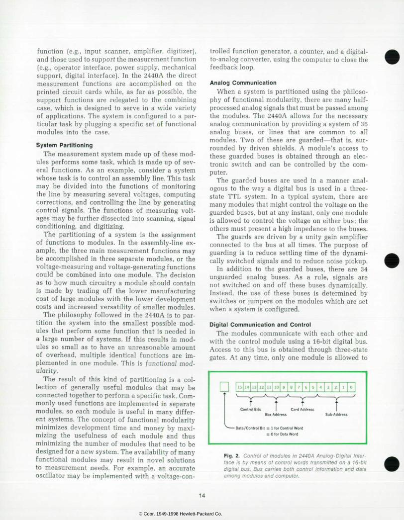
with the control module using a 16-bit digital bus. Access to this bus is obtained through three-state gates. At any time, only one module is allowed to
1 5 1 4 1 3 1 2 1 1 1 0 9 8 7 6 5 4 3 2 1 0
C o n t r o l B i t s C a r d A d d r e s s S u b - A d d r e s s
D a t a / C o n t r o l B i t = 1 f o r C o n t r o l W o r d
= O l o r D a t a W o r d
F i g . 2 . C o n t r o l o l m o d u l e s i n 2 4 4 0 A A n a l o g - D i g i t a l I n t e r f ace i s by means o t con t ro l wo rds t r ansm i t t ed on a 16 -b i t d i g i t a l bus . Bus ca r r i es bo th con t ro l i n fo rma t i on and da ta among modu les and compu te r .
14
© Copr. 1949-1998 Hewlett-Packard Co.

Modular Systems for Sensor-Based Data Acquisition and Control
A n i n c r e a s i n g n u m b e r o f c o m p u t e r a p p l i c a t i o n s , b o t h i n i n dus t r y and resea rch , i nvo l ve t he p rocess ing o f da ta t ha t i s a c q u i r e d i n r e a l t i m e f r o m t r a n s d u c e r s . C o m p u t e r i z e d s y s t ems fo r t hese app l i ca t i ons t ake t he gene ra l f o rm shown i n the b lock d iagram: some rea l - t ime process i s mon i to red and c o n t r o l l e d b y a m i n i c o m p u t e r . I n t h e s e s y s t e m s t h e i n t e r f a c e b e t w e e n t h e c o n t r o l l e r a n d t h e p r o c e s s s e n s o r s c o n s is ts o f two subsys tems: an ana log measurement subsys tem and a d ig i t a l i npu t /ou tpu t subsys tem.
Hewle t t -Packard 's new 9600-Ser ies sys tems are s tandard systems conf igured spec i f ica l ly for th is type o f sensor-based da ta acqu i s i t i on and con t ro l app l i ca t i on . Each 9600 -Se r i es sys tem cons i s t s o f an HP 2100A Compu te r , a t e l ep r i n te r , a pho to reade r , a cab ine t , pe r i phe ra l s app rop r i a te t o t he so f t w a r e o p e r a t i n g s y s t e m ( e . g . , a d i s c d r i v e ) , a n d o f c o u r s e , an ana loa subsys tem and a d ig i ta l subsys tem.
T h e a n a l o g a n d d i g i t a l s u b s y s t e m s i n 9 6 0 0 - S e r i e s s y s tems a"» most o f ten the HP 2440A Ana log-D ig i ta l In te r face and the HP 6940A Mul t ip rogrammer , respec t ive ly . These are n e w , h i g h l y m o d u l a r d e v i c e s d e s i g n e d t o a d a p t t o a w i d e v a r i e t y o f a p p l i c a t i o n s w i t h m i n i m a l s p e c i a l e n g i n e e r i n g . T h e y a r e d e s c r i b e d i n t h e a r t i c l e s b e g i n n i n g o n p a g e s 1 3 and 20.
T h e r e a r e f o u r b a s i c s y s t e m s i n t h e 9 6 0 0 S e r i e s . T h e y d i f fer ch ie f ly in the i r sof tware operat ing systems.
The opera t ing sys tem used in the 9600A, the leas t soph is t i ca ted and leas t expens ive o f the 9600 Ser ies , i s the Bas ic Con t ro l Sys tem (BCS) . BCS a l l ows the use r to m ix p rog ram languages fo r sys tem f l ex ib i l i t y . I t has re loca tab le so f tware f o r e a s e o f p r o g r a m m i n g . I t p r o v i d e s f o r o u t p u t b u f f e r i n g o f da ta t o he lp ma in ta i n sys tem speed , and i t manages t he e n t i r e i n t e r r u p t s y s t e m . T h i s s y s t e m i s w e l l s u i t e d t o t h e ded ica ted da ta -acqu is i t i on sys tem app l i ca t ion .
A d d i n g a t i m e - b a s e g e n e r a t o r a n d s o m e a d d i t i o n a l s o f t w a r e , t h e D a t a A c q u i s i t i o n a n d C o n t r o l E x e c u t i v e ( D A C E ) , resu l t s in the 9600G sys tem. The DACE so f tware a l lows the user to schedu le d i f fe ren t da ta -acqu is i t ion tasks a t d i f fe ren t t imes and to change task pa ramete rs on - l i ne . The 9600G i s i n e s s e n c e a l o w - c o s t c o r e - b a s e d r e a l - t i m e s c h e d u l e r o f da ta -acqu is i t i on and con t ro l p rograms.
M o s t s o p h i s t i c a t e d o f t h e 9 6 0 0 S e r i e s D a t a A c q u i s i t i o n a n d C o n t r o l S y s t e m s a r e t h e 9 6 0 0 E a n d F S y s t e m s , w h i c h a re based on the Rea l -T ime Execu t i ve (RTE) ope ra t i ng sys t e m . T h e s e t w o s y s t e m s a r e t r u e m u l t i p r o g r a m m i n g , f o r e g round-backg round opera t i ng sys tems w i th p r i o r i t y schedu l i n g , i n t e r r u p t h a n d l i n g , a n d p r o g r a m l o a d - a n d - g o c a p a b i l i t i es . Bo th sys tems use a d i sc f o r mass s to rage .
The 9600E sys tem uses t he new HP 7900A Mov ing -Head D isc Dr ive (Hewle t t -Packard Journa l , May 1972) . The 9600F uses a f i xed -head d i sc . The two d i f f e r i n d i sc access t ime ,
the f i xed -head d i sc be ing fas te r , and in da ta s to rage capac i t y . The 9600E has fa r g rea te r s to rage capac i t y : 2 .5 m i l l i on w o r d s p e r d i s c d i s c d r i v e a n d a s m a n y a s f o u r d r i v e s o p e r a ted f rom a s ing le cont ro l ler . Wi th a 9600E or 9600F system, severa l user -p repared p rograms can be run in rea l t ime con cu r ren t l y w i th genera l -pu rpose backg round p rog rams .
R e a l T i m e P r o c e s s
T e m p e r a t u r e s Pressures , e tc .
|
Signal C o n d i t i o n i n g
A n a l o g M e a s u r e m e n t
S u b s y s t e m ( 2 4 4 0 A )
T w o - V a l u e d S i g n a l s ( C o n t a c t C l o s u r e s ,
Logic Leve ls )
Cont ro l
S igna l C o n d i t i o n i n g
Dig i ta l I n p u t / O u t p u t
S u b s y s t e m ( H P 6 9 4 0 A )
T e l e p r i n t e r
O p e r a t o r C o m m u n
icat ions
S y s t e m C o n t r o l l e r
(HP 2 100 A C o m p u t e r )
M a g n e t i c T a p e
or Disc
D a t a C o m m u n i c a t i o n s
( C o m m o n C a r r i e r o r H a r d W i r e )
C R T o r P l o t t e r
HP 9600 Se r ies Da ta Acqu is i t i on and Con t ro l Sys tems
Besides the s tandard hardware and subsystems d iscussed i n t h i s i s s u e , t h e r e a r e s e v e r a l o t h e r o p t i o n a l f r o n t e n d s , s u c h a s D V M s a n d c r o s s b a r a n d r e e d s c a n n e r s . T h e r e a r e a l so pe r i phe ra l s such as magne t i c t ape , CRT d i sp lays , and d a t a c o m m u n i c a t i o n s s y s t e m s . T h u s 9 6 0 0 - S e r i e s s y s t e m s c a n b e c o n f i g u r e d t o s o l v e a v a r i e t y o f s e n s o r - b a s e d d a t a a c q u i s i t i o n a n d c o n t r o l p r o b l e m s . S y s t e m s c a n b e s t a n d a lone o r d i s t r i bu ted , and can au toma te a s i ng le p rocess o r an ent i re factory .
control the state of the digital bus. All other mod ules must be in the 'off or high-impedance state. The digital bus is used to transmit both control information and data among modules. The presence of a control word is indicated by the data/control line, another three-state line associated with the digital bus. A logic one on the data/control line indicates a control word, and a logic zero indicates
a data word. The format of the control word is given in Fig. 2.
The control word contains two types of informa tion: a module address and a function command. Addressing is usually performed according to phy sical position. The address field is divided into three subfields: a box address, a module or card address, and a subaddress. The box address is used
15
© Copr. 1949-1998 Hewlett-Packard Co.
to select one of the eight possible 2440A main frames in a system, the module address picks a module within that box, and the subaddress iden tifies a function on that module.
Within each mainframe, there are separate enable lines running from the control module to each mod ule. The backplane addresses are decoded by the control module, and the appropriate enable line is activated. In a multi-box systsm, a digital expander module inserted in a control module slot performs the enabling of modules.
There are 12 modules per box, so there are four unused module addresses in the 4-bit address space. Since the box address is independent of the card address, in the combined box and module address space there are 32 unused combinations. These combinations may be used to address mod ules by function rather than by physical position. If this method is employed, the card must decode its address from the backplane; none of the enable lines will be activated. Addressing by function is especially useful when many cards must be enabled simultaneously.
If it is desired to pass more than the four-bit function command and the five-bit subaddress to a module, a control word is issued to get the atten tion of the module, and any number of data words (in which the state of the data/control line is zero) may then be issued. The format of the data word is completely free, since no module can be enabled by a data word.
All transfers of information on the backplane are asynchronous and take place in response to commands issued by the control card. There are
two principal reasons for using an asynchronous scheme. First, modules may function at any clock rate, thus freeing the module's internal circuitry from restrictions introduced by the mainframe. Sec ond, it's desirable to have a quiet backplane for analog measurements, and an asychronous scheme requires no clock signal. Where noise is very im portant, it's possible to halt all transfers of data by activating one of the control lines on the back plane.
System Configurat ion Once a library of functional modules is built up,
the design of a system to perform a new task is greatly simplified. When faced with a new require ment, a designer may follow one of three courses, depending on the differences between the new sys tem and previously designed systems. 1) It may be possible to configure the system by plugging the appropriate cards into a mainframe. The ability to change system configuration is not restricted to the designer; a user may take advantage of this feature to modify his system as his requirements change. 2) If all necessary functions are available but a new control feature is needed, the control card may be redesigned or reprogrammed. 3] If some new functions are necessary, the appropriate modules must be designed. These can be used to gether with some of the modules in the library. The newly designed modules may be added to the library, where they should be useful in future systems.
There are limitations to the types of systems that may be implemented using the 2440A. The analog
Low-Leve l I n p u t s
High Level Inputs
H P 2 4 7 1 A D a t a
A m p l i f i e r
Low-Leve l I n p u t s
H P 2 9 3 0 A Low- Level
M u l t i p l e x e r
H i g h L e v e l M u l t i p l e x e r
C a r d
H i g h - L e v e l M u l t i p l e x e r
C a r d
H P 2 9 3 0 A I n t e r f a c e
C a r d
S a m p l e a n d H o l d
A m p l i f i e r
Ana log- to - Dig i ta l
C o n v e r t e r
D a t a Acqu is i t ion
C o n t r o l C a r d
C o n t r o l S i g n a l s for
A l l Cards
H P 2 4 4 0 A A n a l o g - D i g i t a l I n t e r f a c e
C o m p u t e r
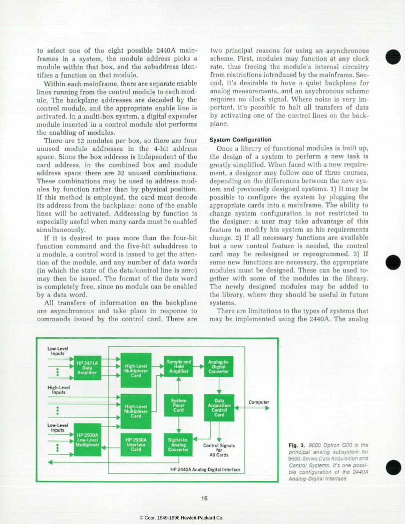
F i g . 3 . 9 6 0 0 O p t i o n G O O i s t h e p r i n c i p a l a n a l o g s u b s y s t e m t o r 9600-Ser ies Data Acquis i t ion and Con t ro l Sys tems . I t ' s one poss i b l e c o n f i g u r a t i o n o f t h e 2 4 4 0 A Analog-Dig i ta l In ter face.
16
© Copr. 1949-1998 Hewlett-Packard Co.

bus is limited in its ability to accommodate high- frequency or low-level signals, and system noise limits the resolution obtainable even on high-level (±10 V) signals. It is difficult to cool modules that have high power dissipation, and the shielding pro vided is not sufficient to isolate low-level cards completely from interference caused by high cur rents flowing in adjacent modules.
Use in 9600 Systems Model 2440A Analog-Digital Interface is the prin
cipal analog subsystem for HP 9600 Series Data Acquisition and Control Systems (see box, page 15). This subsystem, designated 9600 Option GOO, con tains the following plug-in modules (Fig. 3). • A high-level (±10 V full scale) multiplexer, with
a capacity of 16 differential or 32 single-ended signals, the choice being made by positioning jumpers on the card. Single-ended and differen tial channels may be mixed within a subsystem, but not within a module. This module receives its inputs from either the front connector or the
unguarded analog bus, and drives the guarded bus in a differential fashion. An interface to the HP 2930A programmable- gain low-level multiplexer. The HP 2930A has an input range of 10 mV to 10.24 volts program mable in 11 steps. This card can operate up to eight 2930A's (512 channels) and provide all necessary digital signals to the low-level multi plexers, whose analog outputs are interfaced to the 2440A through the high-level multiplexer card. A 12-bit analog-to-digital converter, which uses successive approximation at a 1 micro-second per bit rate for a total conversion time of 12 microseconds. A programmable pacer whose period may be varied from 1 microsecond to 2550 seconds under computer control. Provision is made for external starting or stopping of the pacer if it is desired to synchronize the pulse train to an external event. Another unusual feature is the ability to change the pace rate without losing synchronism with
Unusual Pacer Excels in System Timing
P r e c i s e t i m i n g b e t w e e n m e a s u r e m e n t s c a n b e o n e o f t h e m o r e s e v e r e r e q u i r e m e n t s f a c e d b y t h e d e s i g n e r o f a c o m puter -cont ro l led sys tem. In a l l bu t the s imp les t sys tems, t im i n g m u s t b e u n d e r p r o g r a m c o n t r o l ; h e n c e i t m u s t b e d o n e e i t h e r b y s o f t w a r e o r b y m e a n s o f a p r o g r a m m a b l e p u l s e genera to r o f some type . The p rob lem is tha t the accuracy o f s o f t w a r e t i m i n g i s u s u a l l y l i m i t e d b y t h e r e s o l u t i o n o f t h e compu te r ' s i n te rna l c l ock , and p rog rammab le pu l se gene ra t o r s , w h i l e m o r e a c c u r a t e , t e n d t o b e c o s t l y a n d n o t d e s igned spec i f i ca l ly fo r sys tems use.
S y s t e m s ( e . g . , t h e 9 6 0 0 S e r i e s ) u s i n g M o d e l 2 4 4 0 A A n a log-D ig i ta l In te r face as the i r ana log f ron t end have a un ique t im ing capab i l i t y in the fo rm o f a p lug- in sys tem pacer card . Th is ca rd can supp ly t im ing pu lses w i th more than 1800 d is c r e t e p e r i o d s f r o m o n e m i c r o s e c o n d t o 2 5 5 0 s e c o n d s . T h e pu lse per iod is programmable and accurate to ±0.01%, and p e r i o d - t o - p e r i o d v a r i a t i o n s ( j i t t e r ) a r e l e s s t h a n 2 0 n a n o seconds.
U n l i k e m o s t p u l s e g e n e r a t o r s , t h e s y s t e m p a c e r h a s t h e f o l l o w i n g f e a t u r e s t h a t a r e i m p o r t a n t f o r s y s t e m t i m i n g : D e l a y e d o r i m m e d i a t e s t a r t / s t o p a n d p e r i o d c h a n g e . T h e f i r s t p a c e p u l s e c a n b e i s s u e d i m m e d i a t e l y a f t e r t h e p a c e r i s s t a r t e d , o r i t c a n b e d e l a y e d o n e f u l l p a c e p e r i o d . L i k e w ise , when to ld to s top , the pacer can do so immed ia te ly o r i ssue one more pace pu lse a t the end o f the cur ren t per iod . W h e n c h a n g i n g p e r i o d s , t h e c h a n g e c a n b e i m m e d i a t e , o r d e l a y e d u n t i l t h e e n d o f t h e c u r r e n t p a c e p e r i o d a s s h o w n in the d raw ing . The change-de layed mode , wh ich ma in ta ins s y n c h r o n i s m w i t h t h e p r e v i o u s p u l s e t r a i n , i s u s e f u l w h e n a n a c c u r a t e s t a r t i n g t i m e r e f e r e n c e i s k n o w n a n d m u s t b e maintained.
E x t e r n a l s t a r t / s t o p . A n e x t e r n a l s t a r t / s t o p l i n e i s p r o v i d e d f o r co r re l a t i ng t he sys tem ' s pac i ng w i t h an ex te rna l even t . The pace r w i l l s t a r t o r s top w i t h i n 350 nanoseconds ±150 nanoseconds of the t ime of occurrence of the externa l s ignal a t t he pace r i npu t connec to r .
, System Pace Pulses
(A) = Old Period (g) = New Period
Change-De layed Mode Ma in ta ins Synchron ism When Chang ing Pe r i ods
P a c e e r r o r d e t e c t i o n . T h i s i m p o r t a n t f e a t u r e s e t s a n i n f o r m a t i o n b i t i n t h e d a t a w o r d w h e n e v e r o n e o r m o r e p a c e p u l s e s h a v e b e e n m i s s e d b y t h e s y s t e m . P a c e p u l s e s c a n be missed i f the computer i s too busy serv ic ing o ther per iph e ra l s t o reques t a measu remen t f r om the 2440A. When th i s h a p p e n s t h e 2 4 4 0 A w i l l n o t r e s p o n d t o t h e p a c e p u l s e a n d t i m e c o r r e l a t i o n o f t h e m e a s u r e m e n t s w i l l b e l o s t . W i t h o u t the pace e r ro r b i t i t wou ld be imposs ib le to te l l whe ther the 2440A had been se rv i ced o f ten enough by the compute r . As a secondary bene f i t , t he pace e r ro r f ea tu re may be used to de termine max imum throughput ra te exper imenta l ly (e .g . , by i n c r e a s i n g t h r o u g h p u t u n t i l t o o m a n y p a c e e r r o r s a r e d e tec ted ) . Max imum th roughpu t ra te i s v i r t ua l l y imposs ib le t o pred ic t theoret ica l ly .
17
© Copr. 1949-1998 Hewlett-Packard Co.
H P 2 1 0 0 A C o m p u t e r
H P 2 4 4 0 A Ana log -D ig i ta l
I n t e r f a c e
SJ IT H P 2 7 5 2 A T e l e p r i n t e r
( A S R 3 3 )
H P 2 9 3 0 A Low Level
M u l t i p l e x e r
S p e e d à Operator Control
P a n e l ^
T h r o t t l e S e r v o M i s c e l l a n e o u s C o n t r o l s
D y n a m o m e t e r C o n t r o l
LoadX ie l l
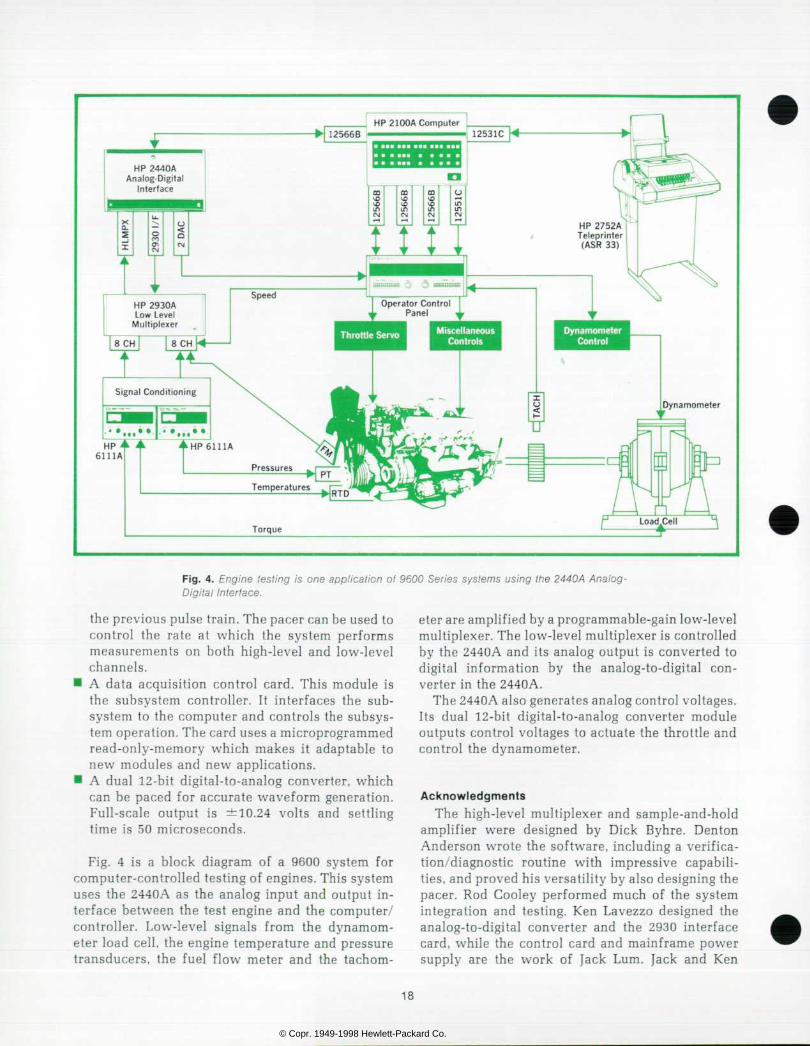
Fig. us ing Analog- test ing is one appl icat ion of 9600 Ser ies systems using the 2440A Analog- Digi ta l Inter face.
the previous pulse train. The pacer can be used to control the rate at which the system performs measurements on both high-level and low-level channels.
• A data acquisition control card. This module is the subsystem controller. It interfaces the sub system to the computer and controls the subsys tem operation. The card uses a microprogrammed read-only-memory which makes it adaptable to new modules and new applications.
• A dual 12-bit digital-to-analog converter, which can be paced for accurate waveform generation. Full-scale output is ±10.24 volts and settling time is 50 microseconds.
Fig. 4 is a block diagram of a 9600 system for computer-controlled testing of engines. This system uses the 2440A as the analog input and output in terface between the test engine and the computer/ controller. Low-level signals from the dynamom eter load cell, the engine temperature and pressure transducers, the fuel flow meter and the tachom
eter are amplified by a programmable-gain low-level multiplexer. The low-level multiplexer is controlled by the 2440A and its analog output is converted to digital information by the analog-to-digital con verter in the 2440A.
The 2440A also generates analog control voltages. Its dual 12-bit digital-to-analog converter module outputs control voltages to actuate the throttle and control the dynamometer.
Acknowledgments The high-level multiplexer and sample-and-hold
amplifier were designed by Dick Byhre. Dentón Anderson wrote the software, including a verifica tion/diagnostic routine with impressive capabili ties, and proved his versatility by also designing the pacer. Rod Cooley performed much of the system integration and testing. Ken Lavezzo designed the analog-to-digital converter and the 2930 interface card, while the control card and mainframe power supply are the work of Jack Lum. Jack and Ken
18
© Copr. 1949-1998 Hewlett-Packard Co.

also contributed a great deal by providing creative solutions to the systems problems encountered dur
ing development. The digital-to-analog converter was designed by Wilson Wong. S
James M . Kasson J im Kasson heads HP's 9600 deve lopment sec t ion , wh ich is respons ib le fo r deve lop ing ded ica ted and genera l - purpose 9600-Ser ies systems. He was former ly pro ject manager for the 2440A Analog-Dig i ta l In ter face. J im received his B. S. E. E. degree from Stanford Universi ty in 1 964 and his M. S. E. E. degree from the University of I l l inois in 1 965. Before coming to HP in 1 969 he was involved in speech bandwid th compress ion and speech recogn i t ion research. His in terests range f rom computers and cybernet ics on the profess ional s ide to populat ion cont ro l , photography, and f ine wines. For outdoor re laxat ion he favors b icyc l ing and backpack ing. J im is a member o f IEEE and the author of several ar t ic les in the electronics press.
P A R T I A L S P E C I F I C A T I O N S
H P 9 6 0 0 S e r i e s Opt ions GOO-G50
D E S C R I P T I O N : A 1 2 - b i t , 4 5 k H z d a t a a c q u i s i t i o n s u b s y s t e m b a s e d o n t h e H P 2 4 4 0 A A n a l o g - D i g i t a l I n t e r f a c e .
R E S O L U T I O N : 1 2 b i t s , I n c l u d i n g s i g n â € ” U S B = 5 m V . F U L L - S C A L E I N P U T : + 1 0 . 2 3 5 V t o - 1 0 . 2 4 0 V . T H R O U G H O U T R A T E T O B U F F E R W / D M A :
T o 4 5 k H z m i n i m u m . A P E R T U R E T I M E : 5 0 n s , p e a k - t o - p e a k t i m e v a r i a t i o n r e a d i n g t o r e a d
i n g , i f p a c e d b y o p t i o n G 5 0 P r o g r a m m a b l e P a c e r . I n c l u d e s s a m p l e - a n d - h o l d a p e r t u r e a n d p a c e p u l s e j i t t e r .
ACCURACY^ : ( t empe ra tu res 10° t o 40°C) : 0 . 09% f s ± ' / 2 LSB (±0 .05% f s i s a d d e d b y o p t i o n G 0 1 ;  ± 0 . 0 6 % f s I s a d d e d b y o p t i o n G 0 2 )  ± 0 . 0 0 2 6 % f s p e r  ° C ;  ± 0 . 0 6 % f s m a x i m u m d r i f t i n 3 0 d a y s .
N U M B E R O F H I G H - L E V E L I N P U T S : P e r O p t . G 1 0 : 3 2 s i n g l e - e n d e d o r 1 6 d i f f e r e n t i a l , j u m p e r s e l e c t a b l e . I n O p t . G O O : O p t i o n G O O I n c l u d e s o n e o p t i o n G 1 0 , c a n h o l d u p
t o e i g h t m o r e o f G 1 0 f o r 2 8 8 s i n g l e - e n d e d / 1 4 4 d i f f e r e n t i a l i n p u t s t o t a l .
O p t . G 0 1 & G 0 2 : E a c h o f t h e s e o p t i o n s a d d s c a p a c i t y f o r 1 2 a d d i t i o n a l o p t i o n G 1 0 m u l t i p l e x c a r d s ; p r o v i d i n g f o r 3 8 4 s i n g l e - e n d e d o r 1 9 2 c a n I n p u t s . O p t i o n s G O O , G 0 1 , & G 0 2 t o g e t h e r c a n h o l d 1 0 5 6 s i n g l e - e n d e d / 5 2 8 d i f f e r e n t i a l I n p u t s t o t a l .
O p t . G 0 3 : L a s t A d d r e s s D e t e c t o r c a r d u s e s o n e h i g h - l e v e l m u l t i p l e x e r c a r d s p a c e .
O p t . G 2 0 : L o w - l e v e l m u l t i p l e x e r i n t e r f a c e c a r d u s e s o n e h i g h - l e v e l m u l t i p l e x e r c a r d s p a c e . T w o l o w - l e v e l m u l t i p l e x e r i n t e r f a c e c a r d s m a y b e u s e d i n a s i n g l e s u b s y s t e m . L o w - l e v e l o p t i o n a l s o u s e s o n e h i g h - l e v e l m u l t i p l e x e r c a r d .
C O M P U T E R I / O C H A N N E L : O n e . L O W - L E V E L M U L T I P L E X E R :
R E S O L U T I O N : 1 2 b i t s , i n c l u d i n g s i g n . T H R O U G H P U T R A T E T O B U F F E R W / D M A : T o 1 4 . 5 k H z , m i n i m u m . N U M B E R O F I N P U T S : 8 t o 6 4 , a d d e d i n e i g h t - i n p u t i n c r e m e n t s .
U p t o 5 1 2 i n p u t s w i t h o n e o p t i o n G 2 0 a n d s e v e n o p t i o n G 2 1 m u l t i p l e x e r s i n t e r f a c e d t o G O O . U p t o 1 0 2 4 i n p u t s w i t h t w o o p t i o n G 2 0 a n d 1 4 o p t i o n G 2 1 m u l t i p l e x e r s i n t e r f a c e d t o G O O .
A C C U R A C Y ( o f A D C a n d L o w - L e v e l M u l t i p l e x e r , 1 0  ° t o 4 0  ° C ) : R a n g e  ± 1 0 . 2 4 V  ± 1 0 m V O v e r a l l ( % f s ) '  ± 0 . 1 8  ± 0 . 4 1 T e m p . C o e f f .  ± 0 . 0 0 5  ± 0 . 0 1 5
(% f s /°C) L o n g - T e r m D r i f t  ± 0 . 0 9  ± 0 . 3 1
( 3 0 d a y s ) ( % f s ) P L U G - I N P R O G R A M M A B L E P A C E R ( 9 6 0 0 S e r i e s O p t i o n G 5 0 ) :
S A M P L E - S A M P L E T I M I N G :
I n t e r v a l R a n g e : 1  ¿ t s t o 2 5 5 0 s i n e i g h t r a n g e s . Reso lu t i on : 1 ¿¡s t o 10 s i n e i gh t s t eps .
A C C U R A C Y O F P A C E I N T E R V A L : W i t h i n  ± 0 . 0 1 % o f p r o g r a m m e d i n t e r v a l .
S U B S Y S T E M A P E R T U R E : 5 0 n s , p e a k - t o - p e a k t i m e v a r i a t i o n , r e a d - I n g t o r e a d i n g , f o r o p t i o n G O O S u b s y s t e m p a c e d b y o p t i o n G 5 0 P r o g r a m m a b l e P a c e r . ( P a c e i n t e r v a l s o f 1 s e c o n d o r l e s s . )
E X T E R N A L I N P U T S I G N A L S : E x t e r n a l S t a r t / S t o p a n d E x t e r n a l C l o c k I n p u t s .
E X T E R N A L O U T P U T S I G N A L S : P a c e P u l s e a n d P a c e G a t e o u t p u t s . P R I C E I N U S A : B a s i c 9 6 0 0 S y s t e m s w i t h O p t . G O O s t a r t a t $ 2 1 , 0 0 0 .
O p t . G 5 0 i s $ 1 5 0 0 . M A N U F A C T U R I N G D I V I S I O N : A U T O M A T I C M E A S U R E M E N T D I V I S I O N
3 9 5 P a g e M i l l R o a d P a l o A l t o , C a l i f o r n i a 9 4 3 0 6
A s s u m e s t h e r e a r e n o i n t e r r u p t s f r o m h i g h e r p r i o r i t y d e v i c e s , n o m a c h i n e c y c l e s u s e d l o r D i r e c t M e m o r y A c c e s s t r a n s f e r o t h e r t h a n t h o s e i n t h i s s u b s y s t e m , a n d n o m o r e t h a n o n e l e v e l o t i n d i r e c t a d d r e s s i n g .
i W i t h r e s p e c t t o s o u r c e u s e d f o r c a l i b r a t i o n . I n c l u d e s t h r e e s i g m a n o i s e ; a n d o f f s e t ; 8 - h o u r s t a b i l i t y g a i n , c a l i b r a t i o n t r a n s f e r , a n d d y n a m i c r e s p o n s e e r r o r s ;  ± 7 0 % l i n e v o l t a g e v a r i a t i o n ; a n d  ± 5  ° C t e m p e r a t u r e v a r i a t i o n . H o l d s l o r s o u r c e r e s i s t a n c e < 1 0 0 C .
W o l d s l o r s a m p l e r a t e s n o g r e a t e r t h a n 2 0 0 s a m p l e s p e r c h a n n e l , o p t i o n G O O S u b s y s t e m w i t h o u t e x p a n d e r s . O p t i o n G 0 1 e x p a n d e r a d d s  ± 0 . 0 5 % f s a n d o p t i o n G 0 2 a d d s  ± 0 . 0 6 % f s t o t h e s e a c c u r a c y f i g u r e s .
19
© Copr. 1949-1998 Hewlett-Packard Co.
Multi prog ram mer Magnifies Minicomputer I /O Capacity When you have an automat ic system wi th dozens or hundreds o f dev ices to cont ro l and moni tor , and only a minicomputer to do the ¡ob, th is minicomputer I /O extender can help.
By John Mickowski
COMPUTERS USED AS CONTROLLERS in automatic systems frequently have to control
and monitor large numbers of display panels, relays, power supplies, X-Y and chart recorders, switches, control valves, status indicators in the form of logic levels and contact closures, and other devices. In a system that requires a relatively small controller memory, or in a large system where a central com puter supervises many smaller satellite controllers or data concentrators, the task of controlling and monitoring this multitude of devices usually falls to a minicomputer. However, a problem may arise be cause a minicomputer generally has a limited num ber of input/output channels, and the cost of adding extra channels may exceed the cost of the inter facing sensors, peripherals and software.
Model 6940A Multiprogrammer and Model 6941A Extender were designed to solve this problem re liably, efficiently, and at reasonable cost. These units expand a single 16-bit computer I/O channel into as many as 240 12-bit channels, each of which can control or monitor from one to twelve devices (see Fig. 1).
An earlier version of the Multiprogrammer, Model 6936A, was designed to replace the individ ually-designed interfaces needed for programming several analog power supplies. Its capabilities were subsequently expanded to include other test system control jobs, such as digital-to-analog-converter outputs, relay contact closures, logic-level outputs, and lamp drivers. The new 6940A Multiprogrammer (Fig. 2) has all of these analog and digital control functions, but it also provides for multiple digital inputs to the computer. It therefore closes the con trol and monitoring loop.
Typical Appl icat ions Potential applications for the new Multiprogram
mer are numerous. Here is a basic list. • Automatic test systems, e.g., for testing relays,
integrated-circuit modules, semiconductors. Any test set requiring variable power sources, contact closures, digital-to-analog converters.
• Efficient (i.e. only one computer I/O slot) con trol of programmable instruments, such as the HP 1900A Pulse Generator system.
• Driving X-Y and chart recorders for process monitoring or display of electronic test results.
• Sensing events and monitoring status in large communication and automatic control systems by monitoring digital input lines.
• Digital data acquisition from remote locations, e.g., counting inventory or production line out put, monitoring and controlling traffic signals.
• Direct digital control and monitoring in process- control systems.
Model 6940A Multiprogrammer is the principal digital subsystem in HP 9600-Series Data Acquisi tion and Control Systems (see box, page 15). It is also available as a separate product.
Mult iprogrammer Organizat ion The Multiprogrammer accepts up to 15 plug-in
cards, each of which represents a 12-bit channel. As many as fifteen Model 6941A Extenders can be chained to one Multiprogrammer and each Extender accepts up to 15 additional cards. Thus as many as 240 12-bit channels can be operated from a single 16-bit computer I/O channel.
Among the many plug-in output cards for the Multiprogrammer there are resistance cards for pro-
20
© Copr. 1949-1998 Hewlett-Packard Co.

r P o w e r S u p p l i e s
C o n t a c t C l o s u r e M o n i t o r i n g
Logic Levels O u t
Logic Levels ,n
F i g . 1 . S i n g l e 1 6 - b i t c o m p u t e r i n p u t / o u t p u t c h a n n e l e x p a n d s t o a s m a n y a s 2 4 0 i n d i v i d u a l l y - a d d r e s s a b l e 1 2 - b i t c h a n n e l s w i t h M o d e l 6 9 4 0 A M u l t i p r o g r a m m e r a n d c h a i n o f 6941 A Mul t ip rogrammer Extenders .
gramming power-supply voltage and current out puts, analog-to-digital converters that produce either voltage or current outputs, digital output cards, either mercury-wetted relays or solid-state, and a breadboard card that makes it possible for the user to design his own output circuits.
Input cards include those that accept digital in puts, either contact closures or logic levels. An event sense card compares a 12-bit input word with a computer-supplied reference word and generates an interrupt if the two words are equal, or are not equal, or if one is greater than the other, all depend
ing on the position of a jumper. There is also a breadboard card for user-designed input circuits.
In addition, there is an accessory custom inter face card that enables the Multiprogrammer to inter face with other than TTL-logic-level computer I/O channels. Interfacing to Hewlett-Packard computers is straightforward with an Interface Kit (Model 14543A) that contains everything necessary to com plete the hardware connection, and software to test and verify the interface.
Mult iprogrammer Operat ion The Multiprogrammer uses a 16-bit-input, 16-bit-
output word format for its interface with the com puter (Fig. 3). The 16-bit input consists of four bits of address and 12 bits of data. The four address bits select which of 15 slots in the multiprogrammer is to receive the other 12 bits. In the case of an input function, the four address bits determine which slot will input data and transmit it to the computer. This combination of 16 bits is called a data word.
To control which box in a multi-unit chain of Multiprogrammers is exchanging data with the com puter, a special code word called the control word is used. It is recognized by the Multiprogrammer when the four address bits are all 1's, correspond ing to the decimal number 15. When the address 15 is detected, the remaining 12 data bits are inter preted by the Multiprogrammer as control informa tion. This information includes the address of the unit in the chain which will receive subsequent data words, as well as bits to control other functions as follows: Bits 0, 1, 2, 3. Unit Address. This selects which unit
in a chain of up to 16 will receive the data words that follow.
Bit 4: Timing Mode Enable. When programmed to a
F i g . 2 . M o d e l 6 9 4 0 A M u l t i p r o g r a m m e r h a s 1 5 I / O c h a n n e l s . Du r i ng sys tem se t -up o r t r oub le s h o o t i n g , e a c h c h a n n e l c a n b e c o n t r o l l e d l o c a l l y t h r o u g h p r o x im i t y sw i t ches on f ron t pane l .
21
© Copr. 1949-1998 Hewlett-Packard Co.

S l o t A d d r e s s
1 2 B i t s Data
D a t a W o r d
IEN,SLDTESYEâ„¢E
C o n t r o l W o r d
F ig . 3 . D ig i ta l words used by Mu l t i p rog rammer . Each chan n e l i s a d d r e s s e d b y b i t s 1 2 - 1 5 i n d a t a w o r d . R e m a i n i n g b i t s c a r r y d a t a . T o c o n t r o l E x t e n d e r s , c o n t r o l w o r d w i t h s p e c i a l a d d r e s s i n b i t s 1 2 - 1 5 p r e c e d e s d a t a w o r d . B i t s 0 -3 i n con t ro l wo rd se lec t Ex tende r t o rece i ve da ta wo rds that fol low.
logical zero, data is transferred to the Multi- programmer at the maximum possible rate. When programmed to a logical one, the computer waits until the Multiprogrammer card has finished its operation before proceeding to program the next data transfer.
Bit 5: System Enable. This control line programs all outputs to a safe mode simultaneously if the sys tem detects an emergency situation.
Bit 6: Data Transfer Enable. By programming this bit to a logical one, any predetermined combina tion of output cards, such as those needed to drive an X-Y display, will simultaneously update their output data.
Bit 7: Input Select. Selecting a one for this bit al lows the addressed card to send 12 bits of input data to the computer. A zero indicates that the computer is sending 12 bits of data to a card.
Bit 8: Interrupt Enable. When this bit is set to a
logical one, cards that have interrupt capability and have been armed to generate interrupts are allowed to send interrupts to the computer. To summarize, the control word sets up the state
of the chain, and the data words exchange 12 bits of information between the computer and one card in the chain of units at a time.
Rel iable System Performance Automatic systems represent substantial invest
ments. The better they perform, and the more re liable they are, the greater is the return on that in vestment. The Multiprogrammer has been designed to enhance system performance and reliability as much as possible.
Features which enhance the dependability of the system are:
• Turn-on states for Multiprogrammer plug-in cards controlling digital outputs or power sup plies are predetermined in hardware and cor respond to safe modes of operation for the de vices controlled.
• Digital data storage is included on all cards, to eliminate excess computer overhead.
• Outputs are programmed to the safe mode in case of power or computer failure.
• The computer ground is isolated from the out put and power supply programming grounds.
Features which increase system performance are: • Provision for simultaneous transfer of data
from any combination of logic level outputs or high-speed analog outputs.
• Conversion of computer logic levels to other levels required in the system.
• Ability to select data transfer timing between the computer and the Multiprogrammer either to proceed at the maximum possible rate, or to be governed by the settling time of the par ticular device being controlled by each output instruction.
F ig . 4 . Mode l 6940A accep ts up t o 1 5 i n p u t a n d o u t p u t c a r d s ( lou r shown here pa r t i a l l y i nse r t e d ) i n a n y c o m b i n a t i o n . C a r d s a r e e a s i l y a d d e d , r e m o v e d , o r i n t e r c h a n g e d t o m o d i f y c a p a b i l i t i es o f da ta acqu i s i t i on and con trol system.
22
© Copr. 1949-1998 Hewlett-Packard Co.

Particular attention has been paid to reliability in the design of the instrument, and the packaging promotes quick diagnosis of system failures and servicing of all modules. All plug-in cards are ac cessible through the front panel, via a door which extends the full width of the instrument (Fig. 4). A switch register on the front panel permits local, manual control of all card slots in a Multiprogram- mer. This is especially useful in setting up or troubleshooting a system since in many instances, setup or troubleshooting is much easier under man ual control than with special software to accom plish system diagnosis. When the Multiprogrammer is under computer control, the manual switch regis ter is locked out of control of the system, and the lights behind the switches indicate the status of the data lines in the Multiprogrammer.
Expandabil i ty Because system requirements often grow, the
ideal system component must be easily expandable. Expansion of a system of Multiprogrammers usually is accomplished with no changes in the computer I/O hardware, since only one interface is necessary for a Multiprogrammer and up to 15 Extenders. If system demands ever exceed the capa bilities of 240 plug-in cards, one additional compu ter I/O channel will double the Multiprogrammer input/output capacity.
Correction T h e a r t i c l e ' N e w C a p a b i l i t i e s i n D i g i t a l L o w - F r e q u e n c y Spec t r um Ana l ys i s , ' (Hew le t t -Packa rd Jou rna l , June 1972 ) s ta ted tha t in a speed-up ana lyzer " there 's a 20- to -100 mi l l i second gap be tween the p rocess ing o f one T-second record a n d t h e n e x t , s o s o m e o f t h e s i g n a l i n f o r m a t i o n i s l o s t . " S p e e d - u p a n a l y z e r s d o n o t e x h i b i t a n y s u c h g a p . T h e g a p tha t the au tho rs i n tended to desc r ibe was the 20 - to -100 ms t ime span be tween ana lys is o f the f i r s t and las t f requenc ies i n a d a t a b l o c k , w h i c h c o u l d h a v e a n e f f e c t o n r e s u l t s o b t a i n e d w i t h n o n s t a t i o n a r y s i g n a l s , o r r a n d o m s i g n a l s i n wh i ch t he re i s s i gn i f i can t co r re l a t i on be tween f r equenc ies .
Speed-up ana lyzers load a samp led and d ig i t i zed wave fo rm i n t o a s h i f t r e g i s t e r a n d c i r c u l a t e i t a t a h i g h r a t e . S i m u l t a n e o u s l y , t h e c i r c u l a t i n g i n f o r m a t i o n i s c o n v e r t e d b a c k t o a n a l o g f o r m , e s s e n t i a l l y t r a n s l a t i n g t h e o r i g i n a l w a v e f o r m s p e c t r u m t o a h i g h e r f r e q u e n c y b a n d . A n a l y s i s o f t h e n e w s p e c t r u m w i t h a b a n d p a s s f i l t e r r e q u i r e s o n e c o m p l e t e c i r cu la t i on o f the da ta fo r each f requency . Norma l l y the ins t ru m e n t d r o p s t h e o l d e s t s a m p l e a n d a d d s a n e w o n e e a c h t ime the da ta c i rcu la tes . Th is means the da ta b lock changes c o n t i n u o u s l y a n d , i f t h e s i g n a l i s n o n s t a t i o n a r y , t h e f r e q u e n c y c o e f f i c i e n t s w i l l n o t b e d e t e r m i n e d o n i d e n t i c a l b locks o f da ta .
Acknowledgments Industrial design of the new Multiprogrammer,
including thermal engineering, was by John Pratt. Many thanks are due Earl Gable, for his consci entious, enthusiastic performance as technician and general expediter, Brett Nordgren for general guid ance and contributions from his systems expertise, and Joseph Skowronski and Robert Willmot for invaluable help in defining the product. S
\
J o h n M i c k o w s k i Recogniz ing the mul t id isc ip l inary character o f today 's techno logy , John Mickowsk i added an MSEE degree to the BSME degree that he had earned in 1967 at the Stevens Inst i tu te of Technology. He 's a member of both the Society o f Automot ive Engineers and Tau Beta Pi .
John 's pro fess iona l career began in 1967 measur ing the per formance of exper imenta l a i rcraf t engines. Then he went 100% e lec t ron ic , jo in ing Hewle t t -Packard as an e lec t ron ic eng ineer work ing on d ig i ta l l y -cont ro l led vo l tage sources. Later he became pro ject leader on the Model 6936A Mul t ip rogrammer wh ich u l t imate ly led to t he Mode l 6940A.
On complet ion of the 6940A pro ject , he e lected to take a 6-month leave of absence f rom h is post as group leader o f the Programmable Ins t rument Group to exp lore some ideas unrelated to his work at HP.
John cont inues to des ign and bu i ld eng ines as a hobby and a lso conjures up e lect romechanica l gadgets . But then he also l ikes to paint in o i ls , p lay squash, and go motorcyc l ing.
© Copr. 1949-1998 Hewlett-Packard Co.

S P E C I F I C A T I O N S HP Mode l 6940A Mul t ip rogrammer
H P M o d e l 6 9 4 1 A E x t e n d e r
F R O N T - P A N E L C O N T R O L S ( 6 9 4 0 A ) : P o w e r O N / O F F s w i t c h a n d i n d i c a t o r l a m p , R E M O T E / L O C A L s w i t c h f o r s e l e c t i n g c o m p u t e r o r m a n u a l c o n t r o l , 1 9 p r o x i m i t y s w i t c h e s f o r m a n u a l d a t a e n t r y a n d c o n t r o l .
F R O N T - P A N E L C O N T R O L S ( 6 9 4 1 A ) : P o w e r O N / O F F s w i t c h a n d i n d i c a t o r l a m p .
I N T E R F A C I N G : 6 9 4 0 A m a i n f r a m e e q u i p p e d w i t h s t a n d a r d i n t e r f a c e c a r d i n t e r f a c e s w i t h b i n a r y s o u r c e s e m p l o y i n g T T L o r D T L m i c r o - c i r c u i t l o g i c . K i t ( 1 4 5 4 3 A ) c o n t a i n i n g n e c e s s a r y h a r d w a r e a n d s o f t w a r e t o i n t e r f a c e w i t h a n y H P c o m p u t e r i s a v a i l a b l e . O p t i o n a l c u s t o m i n t e r f a c e c a r d ( 6 9 3 4 0 A ) i s a l s o a v a i l a b l e t o s a t i s f y c u s t o m e r r e q u i r e m e n t s d i f f e r e n t f r o m t h o s e o f s t a n d a r d c a r d .
I N P U T / O U T P U T C A R D P O S I T I O N S : M a x i m u m o f 1 5 p l u g - i n i n p u t o r o u t p u t c a r d s p e r m a i n f r a m e .
M A I N F R A M E D A T A C O N N E C T O R S : T w o 5 0 - c o n t a c t , r e a r - m o u n t e d , f e m a l e r i b b o n c o n n e c t o r s .
D A T A T R A N S F E R R A T E : 1 0 0 k w o r d / s g u a r a n t e e d m i n i m u m ( m e a s u r e d a t m a i n f r a m e d a t a c o n n e c t o r ) .
M A X I M U M D A T A R E S O L U T I O N : 1 2 b i t s . C O O L I N G : N a t u r a l c o n v e c t i o n . T E M P E R A T U R E R A N G E : 0 t o + 5 5 Â ° C o p e r a t i n g , - 4 0 t o + 7 5 Â ° C
s t o r a g e . W E I G H T ( 6 9 4 0 A ) : 3 5 . 0 I b s ( 1 5 , 9 k g ) . W E I G H T ( 6 9 4 1 A ) . 3 3 . 5 I b s ( 1 5 , 2 k g ) . D I M E N S I O N S : 1 6 y 4 W X 6 % H x 2 1 1 / 4 D ( 4 3 , 5 4 x 1 7 , 2 2 x 5 3 , 9 8 c m ) .
O U T P U T C A R D S S E R I E S E L E M E N T O U T P U T C A R D , M o d e l 6 9 3 0 0 A :
A l l o w s c u s t o m e r t o s e l e c t a n d l o a d o w n s e r i e s - a d d i n g e l e m e n t s , s u c h a s r e s i s t o r s .
O U T P U T C H A N N E L S : O n e 1 2 - e l e m e n t o r t w o i n d e p e n d e n t 6 - e l e m e n t .
P A R A L L E L E L E M E N T O U T P U T C A R D , M o d e l 6 9 3 6 0 A : A l l o w s c u s t o m e r t o s e l e c t a n d l o a d o w n p a r a l l e l - a d d i n g e l e m e n t s ,
s u c h a s c a p a c i t o r s . O U T P U T C H A N N E L S : O n e 1 2 - e l e m e n t o r t w o i n d e p e n d e n t 6 -
e l e m e n t . P O W E R S U P P L Y P R O G R A M M I N G C A R D S , M o d e l s 6 9 3 0 1 A - 6 9 3 1 3 A :
S u p p l i e s r e s i s t a n c e f o r p r o g r a m m i n g v o l t a g e a n d c u r r e n t o u t p u t s o f H P p o w e r s u p p l i e s e q u i p p e d w i t h O p t i o n 0 4 0 .
O U T P U T C H A N N E L S : M o d e l s 6 9 3 0 1 A - 6 9 3 0 4 A , o n e 1 2 - e l e m e n t c h a n n e l f o r p r o g r a m m i n g o u t p u t v o l t a g e o f o n e p o w e r s u p p l y . M o d e l s 6 9 3 1 0 A - 6 9 3 1 3 A , t w o i n d e p e n d e n t 6 - e l e m e n t c h a n n e l s f o r p r o g r a m m i n g o u t p u t c u r r e n t o f t w o p o w e r s u p p l i e s .
V O L T A G E D / A C O N V E R T E R C A R D , M o d e l 6 9 3 2 1 A : P r o v i d e s h i g h - s p e e d b i p o l a r o u t p u t v o l t a g e t h a t i s a n a l o g o f d i g i t a l
i n p u t t o c a r d . ( 6 9 3 5 1 A v o l t a g e r e g u l a t o r a l s o r e q u i r e d . ) O U T P U T : - 1 0 . 2 4 0 t o + 1 0 . 2 3 5 V d c , a t 0 - 5 m A . R E S O L U T I O N : 5 m V d c . ACCURACY: ±2.5 mVdc a t 25°C ±5°C. P R O G R A M M I N G S P E E D : 5 0  ¿ i s m a x t o w i t h i n 5 m V o f f i n a l v a l u e .
C U R R E N T D / A C O N V E R T E R C A R D , M o d e l 6 9 3 7 0 A : P r o v i d e s h i g h - s p e e d c o n s t a n t - c u r r e n t o u t p u t t h a t i s a n a l o g o f d i g i
t a l i n p u t t o c a r d . ( 6 9 3 5 1 A v o l t a g e r e g u l a t o r r e q u i r e d . ) O U T P U T : 0 t o + 2 4 . 4 7 0 m A , a t 0 - 1 1 V d c . R E S O L U T I O N : 1 0 M . ACCURACY: ±5 M a t 25°C ±10°C. P R O G R A M M I N G S P E E D : 1 0 0 A S m a x t o w i t h i n 1 0 / i A o f f i n a l v a l u e .
R E L A Y R E G I S T E R C A R D , M o d e l 6 9 3 3 0 A :
P r o v i d e s 1 2 i n d e p e n d e n t S P S T n o r m a l l y - o p e n c o n t a c t p a i r s . C O N T A C T R A T I N G S : 1 0 0 V d c , 1 0 0 V r m s , 1 . 0 A s w i t c h i n g , 2 8 W
max . P U L L - I N T I M E : 3 . 5 m s m a x . R E L E A S E T I M E : 1 . 0 m s m a x .
R E L A Y O U T P U T / R E A D B A C K C A R D , M o d e l 6 9 4 3 3 A : S i m i l a r t o 6 9 3 3 0 R e l a y R e g i s t e r C a r d , e x c e p t h a s r e a d b a c k ( o u t p u t
d a t a v e r i f i c a t i o n ) c a p a b i l i t y . T T L O U T P U T C A R D , M o d e l 6 9 3 3 1 A :
P r o v i d e s 1 2 b i t s w i t h T T L / D T L c o m p a t i b l e l o g i c l e v e l s . O U T P U T L E V E L S : S t a n d a r d : L O W = 0 t o + 0 . 3 V d c ( s i n k 3 2 m A
m a x ) ; H I G H = + 4 . 5 t o + 5 . 0 V d c ( 1 k s o u r c e i m p e d a n c e ) . O p t i o n 0 7 3 : p o s i t i v e t r u e 5 V d c l o g i c l e v e l s . U s e r - s e l e c t a b l e o p t i o n : 0 t o + 1 2 V d c ( n o m i n a l ) l o g i c l e v e l s o r o p e n - c o l l e c t o r d r i v e r s .
B R E A D B O A R D O U T P U T C A R D , M o d e l 6 9 3 8 0 A : A l l o w s c u s t o m e r t o d e s i g n a n d b u i l d o w n a n a l o g o r d i g i t a l o u t p u t
c i r c u i t .
I N P U T C A R D S D I G I T A L I N P U T C A R D , M o d e l 6 9 4 3 1 A :
M o n i t o r s 1 2 l i n e s o f T T L , D T L , R T L , o r c o n t a c t c l o s u r e l o g i c . A l l l i n e s r e f e r e n c e d t o c o m p u t e r c o m m o n .
I N P U T L E V E L S : O p t i o n 0 6 9 , g r o u n d t r u e 5 V d c l o g i c ; O p t i o n 0 7 0 , g r o u n d t r u e 1 2 V d c l o g i c o r c o n t a c t c l o s u r e s ; O p t i o n 0 7 3 , p o s i t i v e t r u e 5 V d c l o g i c .
I S O L A T E D D I G I T A L I N P U T C A R D , M o d e l 6 9 4 3 0 A : M o n i t o r s 1 2 i n d e p e n d e n t 1 2 V i n p u t s . A l l i n p u t l i n e s a r e i s o l a t e d .
E V E N T S E N S E / I N T E R R U P T I N P U T C A R D , M o d e l 6 9 4 3 4 A : C o m p a r e s 1 2 b i t s o f d i g i t a l i n p u t d a t a ( c o n t a c t c l o s u r e l o g i c ) w i t h
1 2 b i t s o f r e f e r e n c e d a t a s t o r e d o n c a r d , a n d g e n e r a t e s a n i n t e r r u p t s i g n a l w h e n c e r t a i n c o n d i t i o n s a r e m e t .
B R E A D B O A R D I N P U T C A R D , M o d e l 6 9 4 8 0 A : A l l o w s c u s t o m e r t o d e s i g n a n d b u i l d o w n a n a l o g o r d i g i t a l i n p u t
c i r c u i t .
ACCESSORIES C U S T O M I N T E R F A C E C A R D , M o d e l 6 9 3 4 0 A :
P e r m i t s i n t e r f a c i n g 6 9 4 0 A w i t h e x t e r n a l p r o g r a m m i n g s o u r c e s h a v i n g l o g i c - l e v e l , l o g i c - s e n s e , o r t e r m i n a t i o n s p e c i f i c a t i o n s d i f f e r e n t f r o m t h o s e o f s t a n d a r d i n t e r f a c e c a r d .
I N P U T L E V E L S : O p t i o n 0 7 0 , g r o u n d t r u e 1 2 V d c l o g i c l e v e l s ; O p t i o n 0 7 1 , p o s i t i v e t r u e 5 V d c l o g i c l e v e l s ; O p t i o n 0 7 2 , S p e c i a l I n t e r f a c e C a r d ( a l l o w s c u s t o m e r t o s e l e c t a n d i n s t a l l o w n t e r m i n a t i o n n e t w o r k s ) .
6 9 4 0 A I N T E R F A C E K I T , M o d e l 1 4 5 4 3 A : C o n t a i n s n e c e s s a r y h a r d w a r e a n d s o f t w a r e t o i n t e r f a c e 6 9 4 0 A w i t h
a n y H P c o m p u t e r , a n d t o v e r i f y s y s t e m o p e r a t i o n . C H A I N I N G C A B L E A S S E M B L Y , M o d e l 1 4 5 4 1 A :
C o n n e c t s 6 9 4 0 A m a i n f r a m e s t o 6 9 4 1 A m a i n f r a m e s , a n d 6 9 4 1 A ' s t o o t h e r 6 9 4 1 A ' s .
L E N G T H : 1 8 i n c h e s . V O L T A G E R E G U L A T O R C A R D , M o d e l 6 9 3 5 1 A :
O n e r e q u i r e d i n e v e r y m a i n f r a m e c o n t a i n i n g 6 9 3 2 1 A V o l t a g e o r 6 9 3 7 0 A C u r r e n t D / A C o n v e r t e r C a r d s .
P R I C E S I N U S A : 6 9 4 0 A M u l t i p r o g r a m m e r m a i n f r a m e : $ 1 5 0 0 . 6 9 4 1 A E x t e n d e r m a i n f r a m e : $ 9 0 0 1 4 5 4 1 A C h a i n i n g C a b l e A s s e m b l y : $ 1 5 0 . 1 4 5 4 3 A I n t e r f a c e K i t : $ 1 2 5 0 . I n p u t a n d o u t p u t c a r d s r a n g e f r o m $ 2 0 0 t o $ 4 5 0 . B r e a d b o a r d c a r d s a r e $ 7 5 .
M A N U F A C T U R I N G D I V I S I O N : N E W J E R S E Y D I V I S I O N G r e e n P o n d R o a d R o c k a w a y , N e w J e r s e y 0 7 8 6 6
HEWLETT-PACKARD JOURNAL AUGUST 1972 Volume 23 • Number 12
T e c h n i c a l I n f o r m a t i o n f r o m t h e L a b o r a t o r i e s o f H e w l e t t - P a c k a r d C o m p a n y , 1 5 0 1 P a g e M i l l R o a d ,
P a l o A l t o , C a l i f o r n i a 9 4 3 0 4 U . S . A . H e w l e t t - P a c k a r d S . A . , 1 2 1 7 M e y r i n â € ” G e n e v a , S w i t z e r l a n d Y o k a g a w a - H e w l e t t - P a c k a r d L t d . , S h i b u y a - K u , T o k y o 1 5 1 J a p a n
E d i t o r i a l D i r e c t o r : H o w a r d L . R o b e r t s M a n a g i n g E d i t o r : R i c h a r d P . D o / a n
C o n t r i b u t i n g E d i t o r s : R o s s H . S n y d e r , L a u r e n c e D . S h e r g a l i s A r t D i r e c t o r , P h o t o g r a p h e r : A r v i d A . D a n i e l s o n A r t A s s i s t a n t : E r i c a R . H e l s t r o m
A d m i n i s t r a t i v e S e r v i c e s : R u t h G . P a l m e r
© Copr. 1949-1998 Hewlett-Packard Co.