Embed Size (px)
DESCRIPTION
Audiometry
Citation preview

Audiometry Procedures Manual
January 2009

TABLE OF CONTENTS
Chapter Page
1 INTRODUCTION ........................................................................................... 1-1 1.1 History and Overview of Hearing Examinations in NHANES........... 1-1 1.2 Basic Principles of Sound ................................................................... 1-5 1.3 Basic Principles of Audition ............................................................... 1-8 1.4 Basic Principles of Hearing Loss........................................................ 1-11 1.5 References........................................................................................... 1-13
2 EQUIPMENT .................................................................................................. 2-1
2.1 Description of Exam Room in MEC................................................... 2-1 2.2 Description of Equipment and Supplies ............................................. 2-2
2.2.1 Otoscope.............................................................................. 2-9 2.2.2 Tympanometer .................................................................... 2-9 2.2.3 Audiometer.......................................................................... 2-9 2.2.4 Bioacoustic Simulator ......................................................... 2-10 2.2.5 Sound Level Meter and Accessories ................................... 2-10 2.2.6 Inventory Procedures .......................................................... 2-11
2.3 Start of Stand Procedures.................................................................... 2-11
2.3.1 Room Setup......................................................................... 2-11 2.3.2 Start of Stand Calibrations .................................................. 2-13 2.3.3 Recording Serial Numbers .................................................. 2-14
2.4 Calibration Checks.............................................................................. 2-15
2.4.1 Bioacoustic Simulator Calibration Check ........................... 2-15 2.4.2 Audiometer Calibration Checks .......................................... 2-18
2.4.2.1 Acoustic Calibration Check................................. 2-18 2.4.2.2 Audiometer Bioacoustic Check ........................... 2-29 2.4.2.3 Audiometer Listening Check............................... 2-33
2.4.3 Tympanometer Calibration Check ...................................... 2-36 2.4.4 Troubleshooting Calibration Problems ............................... 2-39
2.5 Environmental Noise Survey .............................................................. 2-40
2.5.1 Environmental Noise Principles.......................................... 2-40 2.5.2 Environmental Noise Survey Procedure ............................. 2-40 2.5.3 Daily Monitoring of Ambient Noise Levels ....................... 2-43
iii

TABLE OF CONTENTS (continued)
Chapter Page
2.6 Daily Procedures................................................................................. 2-44
2.6.1 Set Up and Calibration ........................................................ 2-44 2.6.2 Changing Equipment After Start of Stand .......................... 2-44 2.6.3 Procedures at the End of an Exam Day............................... 2-46
2.7 Weekly Procedures ............................................................................. 2-46 2.8 Equipment Care and Maintenance Procedures ................................... 2-46
2.8.1 Sound Level Meter and Accessories ................................... 2-46
2.8.1.1 General Handling................................................. 2-46 2.8.1.2 Changing Batteries .............................................. 2-47 2.8.1.3 Annual Calibration .............................................. 2-48
2.8.2 Bioacoustic Simulator ......................................................... 2-48
2.8.2.1 Changing the Battery........................................... 2-48 2.8.2.2 Calibration ........................................................... 2-49
2.8.3 Otoscope.............................................................................. 2-49
2.8.3.1 Assembling the Otoscope .................................... 2-49 2.8.3.2 Charging the Battery............................................ 2-49 2.8.3.3 Cleaning the Eyepiece ......................................... 2-50 2.8.3.4 Changing the Otoscope Lamp ............................. 2-51
2.8.4 Tympanometer .................................................................... 2-51
2.8.4.1 Cleaning the Probe Cuffs..................................... 2-51 2.8.4.2 Cleaning the Probe Tip........................................ 2-51 2.8.4.3 Annual Calibration .............................................. 2-52
2.8.5 Audiometer.......................................................................... 2-53
2.8.5.1 General Handling................................................. 2-53 2.8.5.2 Annual Calibration .............................................. 2-53
2.9 End of Stand Procedures..................................................................... 2-53
2.9.1 End of Stand Calibrations ................................................... 2-53 2.9.2 Room Teardown.................................................................. 2-54 2.9.3 Guidelines for Packing Audio Equipment .......................... 2-55
iv

TABLE OF CONTENTS (continued)
Chapter Page
3 EXAMINATION PROTOCOL....................................................................... 3-1 3.1 Eligibility Criteria ............................................................................... 3-1 3.2 Pre-examination Procedures ............................................................... 3-1
3.2.1 Preliminary Activities ......................................................... 3-1 3.2.2 Pre-Exam Questionnaire ..................................................... 3-2
3.3 Otoscopy ............................................................................................. 3-6
3.3.1 Purpose of Otoscopy ........................................................... 3-6 3.3.2 Instrumentation for Otoscopy ............................................. 3-6 3.3.3 Procedure for Otoscopy....................................................... 3-6 3.3.4 Recording Results of Otoscopy........................................... 3-9
3.4 Acoustic Immittance ........................................................................... 3-12
3.4.1 Purpose of Acoustic Immittance ......................................... 3-12 3.4.2 Instrumentation for Acoustic Immittance ........................... 3-13 3.4.3 Procedure for Acoustic Immittance..................................... 3-13 3.4.4 Recording Results of Acoustic Immittance......................... 3-16 3.4.5 Troubleshooting Acoustic Immittance ................................ 3-17
3.5 Audiometry ......................................................................................... 3-18 3.5.1 Purpose of Audiometry ....................................................... 3-18 3.5.2 Instrumentation for Audiometry ......................................... 3-19 3.5.3 Procedure for Audiometry................................................... 3-19
3.5.3.1 Preliminary Procedures and Instructions............. 3-19 3.5.3.2 Automated Audiometry Procedures .................... 3-21 3.5.3.3 Manual Audiometry Procedures.......................... 3-24
3.5.4 Recording Audiometry Results in ISIS............................... 3-28 3.5.5 Retesting with Insert Earphones.......................................... 3-29
3.5.5.1 Crossover Principles ............................................ 3-29 3.5.5.2 Procedure for Retesting with Insert Earphones ... 3-30
3.5.6 Recording Retest Results in ISIS ........................................ 3-31 3.5.7 Considerations to Ensure Threshold Accuracy ................... 3-31 3.5.8 Difficult Test Situations ...................................................... 3-32 3.5.9 Troubleshooting Audiometry .............................................. 3-35
v

vi
TABLE OF CONTENTS (continued)
Chapter Page
3.6 Post-Examination Procedures ............................................................. 3-36 3.6.1 Closing the Hearing Exam in ISIS ...................................... 3-36 3.6.2 Referral................................................................................ 3-37 3.6.3 Directions to Examinee ....................................................... 3-38 3.6.4 Final Procedures.................................................................. 3-38
4 QUALITY CONTROL.................................................................................... 4-1
4.1 Quality Control Procedures ................................................................ 4-1 4.2 Review of Data ................................................................................... 4-2 4.3 Field Observations .............................................................................. 4-2
List of Appendixes
Appendix
A Inventory of Audiometric Equipment and Supplies ........................................ A-1
List of Tables
Table
1-1 Review of NHANES audiometric procedures ................................................. 1-2
List of Figures
Figure
1-1 Schematic representation of sound propagation .............................................. 1-5 1-2 Sound levels of various activities .................................................................... 1-7 1-3 Schematic diagram of the ear........................................................................... 1-9

1. INTRODUCTION
1.1 History and Overview of Hearing Examinations in NHANES
Hearing is important. It is the sensory channel by which we are connected to other people,
warned of impending dangers, and entertained by music and laughter. Good hearing enables us to
perceive the laughter of friends, the cries of a baby, and the breeze rustling through the trees. Without it,
we feel isolated from the world around us, and frustrated by our inability to fully understand the flurry of
activity that surrounds us. Man is a social creature, and hearing is critical to his ability to function as such.
Hearing loss is a widespread problem. More than 36 million people in the United States have
some degree of hearing impairment, making it the third most common health problem in the U.S. While
the prevalence of hearing loss increases with age, it is not merely a problem of the elderly. Two or three
out of every 1,000 children born in the U.S. are deaf or hard-of-hearing. Approximately 8 percent of
children under age 18 have an educationally-significant hearing loss. About one-third of Americans over
age 65 and nearly half of those over age 75 have hearing trouble. An estimated ten million Americans
have hearing loss caused by overexposure to noise, which is a completely preventable problem. Only
about 25 percent of individuals who could benefit from a hearing aid actually use one
(http://www.hearingspeech.org/information.htm).
In addition, an estimated 36 million Americans have tinnitus (ringing in the ears), a
condition which can be as disabling as hearing loss. Over two million of these individuals experience an
incapacitating tinnitus which interferes with daily living activities (Heller, 2003).
Hearing loss can be caused by a myriad of factors—age, noise exposure (occupational or
recreational), developmental syndromes, infectious disease, physical trauma, ototoxic drugs, and
chemicals — all of which are further influenced by genetic susceptibility. Hearing loss is an “invisible”
impairment; that is, there are usually no obvious external signs of the damage that is done. In children, it
often goes undetected for some time while parents, educators, or health professionals mistake the signs of
hearing difficulty for behavior problems or learning disabilities. In older individuals, hearing loss usually
develops gradually and insidiously over time. Because of this, hearing loss is frequently misinterpreted by
the individual as “mumbling” by others or “getting used to” sounds. Others often misinterpret someone’s
1-1

hearing difficulty as inattentiveness or dementia. Often, extensive and irreparable damage has been done
to the auditory system before it is noticed.
The National Center for Health Statistics (NCHS) has regularly included evaluations of the
auditory system in its health examination surveys. These evaluations have included one or more of the
following: a brief medical examination of the ear (otoscopy), interview questions regarding hearing
ability and ear diseases, tympanometry (a test of middle ear function), pure tone air conduction
audiometry, pure tone bone conduction audiometry, and/or speech discrimination testing. Sometimes
these evaluations have been done on all NHANES examinees, and some surveys included hearing
evaluations on only a subset of examinees (such as children or adults). Table 1-1 summarizes the
audiometric procedures included in each of the health examination surveys since 1960:
Table 1-1. Review of NHANES audiometric procedures
Pure tone testing
Survey Years Age Tympanometry 250
500
1000
2000
3000
4000
6000
8000
Bon
e
SpeechNHES* I 1960-1962 18-74 NHES II 1963-1965 6-11 NHES III 1966-1970 12-17 NHANES I 1971-1974 25-74 Augmented 1974-1975 25-74 NHANES II 1976-1980 4-19 HHANES** 1982-1984 6-74 NHANES III 1988-1994 6-19 NHANES 99-04 1999-2004 20-69 NHANES 05-06 2005-2006 12-19, 70+ NHANES 07-08 2007-2008 12-19 NHANES 09-10 2009-2010 12-19, 70+ * National Health Examination Survey.
**Hispanic Health and Nutrition Examination Survey.
It can be seen from the table that young adults had their hearing tested in the NHANES III
cycle that ran from 1988-1994. Analysis of that data indicated that 13 percent of children aged 12-19
years had some degree of high frequency hearing loss. Most of these hearing losses were consistent with
early noise-induced damage (Niskar et al., 1998; Niskar et al., 2001). Because of the alarming rate of
possible noise-induced hearing loss in this subpopulation, and because hearing loss from this cause is
completely preventable, testing youth aged 12-19 began again in 2005 and is continuing. Hearing loss in
this age range is an important public health problem. The NHANES hearing data currently being collected
1-2

will enable researchers to evaluate the effectiveness of current prevention activities and properly target
future interventions among teens.
Table 1-1, shown earlier, also indicates that the older adult population of the United States
has seldom received audiometric testing as part of these national surveys. As the prevalence of hearing
loss increases with age, this segment of the population is assumed to be the most affected by hearing
difficulties. NHANES participants aged 70 and older had their hearing tested during the 2005-06 survey
cycle; however, hearing testing was dropped for this age range in 2007 due to time constraints. It is being
added again for the 2009-10 NHANES cycle. These data will be very important, as most of the current
national prevalence estimates for hearing loss among older individuals are based on self-report which
often underestimates the true extent of the problem (Clark et al., 1991).
Although in the past, NHANES has been a periodic survey, it is currently authorized to run
continuously. This has made it possible to use NHANES to collect data to monitor progress toward health
objectives outlined in Healthy People 2010—the prevention agenda for the Nation (U.S. DHHS, 2000).
Healthy People is a national health promotion and disease prevention initiative created by the Federal
Government to provide a framework for monitoring progress toward identifying and reducing significant,
preventable health problems, increasing the quality and years of healthy life, and eliminating health
disparities. The current Healthy People program includes eight hearing-related objectives, at least five of
which rely on data collected through NHANES for baseline measurements or monitoring progress. These
objectives include:
Increase access by persons who have hearing impairments to hearing rehabilitation
services and adaptive devices, including hearing aids, cochlear implants, or tactile and other assistive or augmentive devices (28.13);
Increase the proportion of persons who have had a hearing examination on schedule (28.14);
Increase the use of appropriate ear protection devices, equipment and practices (28.16);
Reduce noise-induced hearing loss in children and adolescents under age 17 years (28.17); and
Reduce adult hearing loss in the noise-exposed public (28.18).
1-3

The current protocol for the hearing examination component of the NHANES was developed
by NCHS in collaboration with the National Institute for Occupational Safety and Health (NIOSH) and
NIDCD in 1999. The examination includes several parts:
Questionnaire items – hearing-related questions included on both the household
questionnaire (self-reported hearing ability; use of hearing aids and hearing protective devices; relevant medical history; noise exposure history) and in the mobile examination center questionnaire (current conditions that could affect the results of audiometric testing);
Otoscopy – a cursory physical examination of the outer ear;
Acoustic immittance – an objective evaluation of middle ear function; and
Pure tone air conduction audiometry – a basic evaluation of hearing sensitivity.
Information obtained through the audiometric examinations conducted in the NHANES will
provide data for which there has long been a need. Researchers throughout the United States will utilize
these data as a reference population for studies of hearing ability in particular subpopulations. The data
will also provide a baseline from which to measure future progress in preventing hearing loss from noise,
ototoxic exposures, medical conditions, and the like. Specifically, the goals of the current NHANES
hearing component are to:
1. Establish technically valid and statistically representative threshold data describing the
hearing sensitivity of the U.S. population aged 70 years and older stratified by gender, race, socioeconomic status, geographic region, and other variables;
2. Define the prevalence of hearing impairment among U.S. adults age 70 years and older, and quantify the association between prevalence and factors such as noise exposure, medical conditions, ototoxicity from chemical exposures or pharmaceuticals, etc.;
3. Monitor the prevalence of early hearing losses consistent with overexposure to noise among U.S. youth aged 12-19 years, evaluate progress toward prevention during the last decade, and identify particular subpopulations at risk for targeted prevention programs; and
4. Monitor progress toward Healthy People 2010 hearing-related goals.
You, as a health technologist for the NHANES, play a crucial role in collecting these
important data. You will be responsible for conducting the examinations, monitoring the equipment
calibration and test environment, maintaining the equipment and troubleshooting difficulties, and keeping
relevant records. You will not be expected to interpret the test results or provide feedback to the survey
1-4

participants (SPs). You will receive extensive training to ensure that you understand and are able to carry
out these protocols. Nationally-representative surveys such as NHANES are expensive and require
significant planning and oversight to ensure technically accurate information. Please always follow the
standardized procedures that have been developed for the hearing component, which are outlined in this
manual. While some of the procedures may appear to be simple, it is critical that you follow them exactly,
so that data on each examinee are obtained in a uniform manner. If you are ever uncertain about any
procedure or examinee, always ask your supervisor.
Before discussing the specific protocol for the NHANES hearing component, it is important
to cover some basic information about sound and audition. A rudimentary knowledge of the physiology
of hearing is essential to understanding how to test hearing.
1.2 Basic Principles of Sound
Sound can be defined in the physical sense as a series of pressure waves caused by a
vibrating object and propagated through an elastic medium (see Figure 1-1). In other words, sound is
initiated when an object begins to vibrate. As the object moves back and forth, it “bumps into” molecules
in the surrounding area, forcing them to move also. These displaced molecules in turn put pressure on
other molecules and thus the sound wave is propagated. Because the molecules return to their original
resting position following displacement, sound is said to occur in an “elastic” medium.
The small dots in the top of the diagram represent air molecules moving back and forth from their resting position, creating pressure “waves.”
The lower part of the diagram depicts the pressure wave graphically. (From Suter A.H. Hearing Conservation Manual, 3rd Edition. Council for Accreditation in Occupational Hearing Conservation, Milwaukee, 1993.)
Figure 1-1. Schematic representation of sound propagation
1-5

In the physiological sense, sound can be defined as the sensation evoked in the auditory
system by these pressure changes. This will be discussed further in Section 1.3.
Sound may be characterized along three main parameters: frequency, intensity, and
complexity. Frequency is the rate of the sound pressure waves, or how often the molecules are displaced
in a given period of time. Frequency is measured in Hertz (Hz), or cycles per second, and is perceived as
pitch. Lower-pitched sounds (such as the rumble of traffic or a man’s speaking voice) are lower in
frequency; higher-pitched sounds (such as a whistle or a baby’s cry) have higher frequencies.
Intensity refers to the amplitude of the pressure waves, or how far the molecules are
displaced from their original position. Amplitude is measured in decibels and is perceived as volume, or
loudness. Low amplitude sounds (in which the molecules are displaced only a little bit) are perceived as
“quiet” and high amplitude sounds (in which the displacements are larger) are perceived as “loud.”
Complexity refers to the interaction of the various frequencies and intensities that make up a
sound. For example, a pure tone is a sound that is made up of only one frequency and one intensity. Most
sounds are made up of many frequencies at different intensities combined to make a very complex signal.
Complexity is perceived as sound quality or timbre. If a flute and violin are playing the same note at the
same volume, complexity is the parameter of sound that allows us to distinguish between the two
instruments.
Within the context of NHANES, we will be concerned primarily with the frequency and
intensity of signals. The human ear is responsive to frequencies from about 20 to 20,000 Hz, but not
equally so. It is most sensitive from about 1000 to 3000 Hz; and the frequencies most necessary for the
understanding of speech are 500 to 4000 Hz. Audiometry conducted as part of the current NHANES will
include test frequencies from 500 to 8000 Hz.
Test frequencies in audiometry are derived from the musical scale, and are generally octave
intervals. An octave is a tone with a frequency that is exactly twice that of a reference tone. Therefore, the
basic audiometric test frequencies are 500, 1000, 2000, 4000, and 8000 Hz. In addition, testing is often
done at 3000 and 6000 Hz (sometimes called the inter-octave frequencies) because these frequencies are
useful in identifying hearing losses due to noise exposure.
1-6

Intensity is a little more complicated. Remember that intensity refers to amplitude, or how
far the molecules are displaced from their resting position by the vibrating object that is creating the
sound. The farther the molecules are displaced, the greater pressure they place on neighboring molecules.
Thus, intensity is measured in units of pressure; the higher the pressure, the louder the sound.
However, the difficulty is that the human ear is responsive to a very wide range of pressures.
The pressure of a sound that is just barely audible to a young, normal-hearing listener is approximately
20 µPa (the µPa—micropascal—is a unit for measuring pressure). The pressure of a sound that is
painfully loud could be about 200,000,000 µPa. Because it is a bit cumbersome to use such a large range
to quantify intensity, we convert the pressure measurements to decibels. In decibels, the human ear is
responsive to intensities from 0 dB to 140 dB—a much more manageable range. Figure 1-2 illustrates the
sound levels of some common activities and shows the relationship between sound pressure in
micropascals and sound level in decibels.
The intensity of the sound is shown in micropascals on the left and decibels on the right. (From Suter A.H. Hearing Conservation Manual, 3rd
Edition. Council for Accreditation in Occupational Hearing Conservation, Milwaukee, 1993).
Figure 1-2. Sound levels of various activities
1-7

The decibel scale is logarithmic rather than linear; this means that the difference in actual
sound pressure from one decibel to the next increases as the decibel level increases. For example, the
increase in pressure from 20 to 40 dB is not the same as the increase in pressure from 40 to 60 dB. As you
can see from the scale in Figure 1-2, shown earlier, pressure increases by 1800 µPa from 20 to 40 dB, but
pressure increases by 18,000 µPa from 40 to 60 dB. Because of the logarithmic nature of the scale,
decibels cannot be added and subtracted in the usual way. Two independent sound sources that each have
an intensity of 90 dB produce a sound level of about 93 dB when they are put together, not 180 dB.
There are several different decibel scales used in measuring sound and hearing. When
measuring sound levels at different frequencies in the environment (for example, when you measure the
background noise levels in the test room as described in Section 2.5.2), the sound pressure level scale is
used; results are recorded in dB SPL. When measuring an individual’s hearing thresholds (for example,
when doing pure tone audiometry as described in Section 3.5.3), the hearing level scale is used; results
are recorded in dB HL. A measurement of 30 dB SPL is not the same as a measurement of 30 dB HL.
Finally, it is important to note that a measurement of 0 dB does not mean that there is no
sound at all—just like a temperature of 0◦F does not mean that there is no heat at all. There are sounds
that are quieter than 0 dB, and these sounds are measured in negative decibels in the same way that
temperatures colder than 0◦ are measured in negative degrees.
1.3 Basic Principles of Audition
When you think of the ear, you probably think primarily of the two most visible portions of
the auditory system that are located on either side of the head. However, the ear is much more than this.
The ear actually has four main parts: the outer ear, the middle ear, the inner ear, and the auditory neural
system (see Figure 1-3).
The outer ear consists of the auricle (sometimes called the pinna) and the ear canal (also
called the external auditory meatus). The outer ear functions primarily to funnel sound into the ear, and to
modify, to some extent, the acoustic signal. The shape and size of the ear canal cause it to amplify signals
with frequencies of approximately 2000-3000 Hz; this is the main reason that human hearing is most
sensitive in this frequency range.
1-8

The middle ear consists of the eardrum (or the tympanic membrane); three tiny bones (or
ossicles) called the malleus, the incus, and the stapes; and two small muscles. The primary function of the
middle ear is to transform the acoustic signal into mechanical vibration. The middle ear muscles form part
of a reflex arc (known as the acoustic reflex), which provides some small amount of protection against
loud sounds. The middle ear also houses an opening to the eustachian tube, which connects this part of the
ear to the back of the throat. The eustachian tube permits ventilation of the middle ear space, which
maintains a balance in air pressure on either side of the eardrum; this balance is necessary in order for the
eardrum to respond to sound most efficiently.
(From Suter A.H. Hearing Conservation Manual, 3rd Edition. Council for Accreditation in Occupational Hearing Conservation, Milwaukee,
1993).
Figure 1-3. Schematic diagram of the ear
The inner ear consists of the cochlea, which is contained within a spiral opening in the
temporal bone of the skull. The cochlea is divided into three parallel, fluid-filled ducts. The upper and
lower ducts are connected at one end; and a wave is set up in them as the ossicles vibrate in response to
1-9

sound. The middle duct contains rows of tiny hair cells. These hair cells are bent as the wave comes to a
peak; the bending of the hair cells stimulates the auditory nerve. The inner ear therefore serves to
transform the mechanical vibrations from the middle ear into neural impulses.
The auditory neural system consists of the auditory nerve and the auditory areas of the
cortex. This system carries the neural impulses to the brain and interprets them.
The auditory system is complete and possesses normal adult sensory function approximately
half-way through prenatal development. The ability of the auditory neural system to process signals,
however, continues to develop for several years. Newborns are able to discriminate sounds on the basis of
frequency, intensity, and type of stimulus. (They prefer human speech!) Over the first few months, infants
learn to localize, associate hearing with their own vocal productions, and gradually to better and better
imitate the vocal sounds of others. By 1 year of age, they are able to process the meaning of
approximately 50 words. By age 4, children can process and understand just about everything they hear.
Auditory sensitivity reaches its peak at adolescence and then begins a very gradual decline.
Barring any insult that would accelerate the decline (such as noise or disease), the reduction in sensitivity
is not generally clinically measurable until at least the third decade of life. After about age 60, hearing
sensitivity decreases by an average of about 10 dB per decade. The decrease in hearing sensitivity begins
at the highest frequencies and gradually progresses to include the middle and low frequencies. Hearing
loss due to age-related changes is called presbycusis.
There are a number of other age-related changes that occur in the ear. The cartilage in the
outer ear and the ear canal begins to deteriorate, causing the auricle and canal opening to become very
soft; this can cause a condition known as “canal collapse,” which can affect hearing test results
(see Section 3.3.3). Additionally, the ear canal narrows and cerumen becomes drier; these conditions
combine to impede the natural expulsion of wax from the ear canal. Cerumen becomes more easily
trapped, potentially partially or completely blocking the ear canal and causing a temporary loss of
hearing. The tympanic membrane may become less flexible and there can be slight degenerative changes
in the joints between the bones in the middle ear; however, these issues are typically not significant
enough to affect hearing sensitivity (AgeWorks, 2008).
1-10

1.4 Basic Principles of Hearing Loss
Dysfunctions anywhere along the auditory pathway can cause hearing loss. Hearing losses
may be divided into several categories based on where in the ear the impairment is located (the type of
hearing loss), how severely the impairment affects a person’s hearing sensitivity (the degree of hearing
loss), and which ears are affected (the laterality of the hearing loss).
Hearing losses that are caused by a problem in the external or middle ear are called
conductive hearing losses, because the difficulty lies in the conduction of sound to the cochlea. For
example, excessive wax in the ear canal, fluid in the middle ear brought on by an infection, or a
discontinuity between the ossicles would prevent sounds from reaching the inner ear efficiently. These
types of hearing losses are often medically or surgically correctable.
Hearing losses that are caused by a problem in the inner ear or along the auditory nerve are
called sensorineural hearing losses, because the difficulty lies in the ability of the cochlea to sense the
sound or the ability of the nerve to carry the signal to the brain. Damage to the cochlear hair cells due to
age-related deterioration, repeated noise exposure, or a tumor on the auditory nerve are examples of
etiologies that would lead to sensorineural hearing impairment. These types of hearing losses are not
usually medically correctable. Often, sensorineural hearing loss can be remediated to a certain extent with
hearing aids. However, while hearing aid technology has improved immensely over the past few years,
hearing aids do not restore normal hearing in the same sense that eyeglasses restore normal vision.
Classifying degree of hearing loss is much more complex. The severity of the handicap due
to abnormal hearing thresholds depends on a number of interrelated factors, such as the age of the
individual, the age at which the impairment was first sustained, the point of damage within the auditory
system, the individual’s communicative environment and needs, the presence or absence of other illnesses
or sensory deficits, etc. For example, a person who has had significant hearing loss since birth is affected
differently than someone who acquires a similar hearing loss after reaching adulthood. A person with a
conductive hearing loss (which causes simply a reduction in the audibility of sounds) is affected
differently than someone with a sensorineural hearing loss (which often causes a reduction in the
intelligibility as well as the audibility of sounds), even if their thresholds are the same. And a person
whose only sensory impairment is hearing loss is affected differently than someone with the same hearing
thresholds but who also has significant visual or mobility impairments.
1-11

Nevertheless, some basic scheme for classifying severity of hearing loss is necessary.
Although there is no one universally accepted method of defining degree of hearing loss, the following
system is generally representative of the various schemes currently in use:
0-25 dB Normal hearing;
26-40 dB Mild hearing loss;
41-55 dB Moderate hearing loss;
56-70 dB Moderately severe hearing loss;
71-90 dB Severe hearing loss; and
91+ dB Profound hearing loss.
Quite often, an individual has different degrees of hearing loss at different frequencies. For
example, normal hearing in the low frequencies and gradually worsening hearing sensitivity in the high
frequencies is typical of age-related and noise-related impairments. In cases such as these, the
classification scheme may be applied to each test frequency individually (for example, “normal hearing
sensitivity through 1000 Hz, gradually sloping to a moderately-severe hearing loss at the highest test
frequencies”); or thresholds at various frequencies may be averaged and an overall hearing loss rating
may be assigned. Here again, however, there is little agreement as to which frequencies ought to be
averaged. The American Speech-Language Hearing Association (1981) and NIOSH (1996) classify
hearing impairment according to the average hearing threshold at 1000, 2000, 3000, and 4000 Hz. Other
recommendations include average thresholds at 500, 1000, and 2000 Hz or an average of 1000, 2000, and
3000 Hz. Some schemes even involve weighting the various frequencies included in the average.
Audiometric results obtained in NHANES will be reviewed by an audiologist who will determine the
scheme to be used in classifying degree of hearing loss.
Finally, hearing losses may be classified as either unilateral (affecting only one ear) or
bilateral (affecting both ears). Bilateral hearing losses may be symmetric (approximately the same in each
ear) or asymmetric (worse in one ear than the other). Hearing losses from environmental causes (such as
noise, ototoxic chemicals, and aging) are generally bilateral and symmetric. Hearing losses from medical
causes (such as ear infections, mumps, and acoustic tumors) are often unilateral or asymmetric. A
substantial difference in hearing sensitivity between ears can therefore be indicative of a medically
significant condition.
1-12

1-13
1.5 References
AgeWorks (2008). Changes with aging: hearing. Accessed online 10/16/2008 at http://www.ageworks.com/information_on_aging/changeswithaging/aging3.shtml.
Clark, K., Sowers, M.F., Wallace, R.B., and Anderson, C. (1991). The accuracy of self-reported hearing loss in women aged 60-85 years. American Journal of Epidemiology, 134(7):704-708.
Heller, A.J. (2003). Classification and epidemiology of tinnitus. Otolaryngologic Clinics of North America, 36(2):239-248.
Niskar, A.S., Kieszak, S.M., Holmes, A., Esteban, E., Rubin, C., and Brody, D.J. (1998). Prevalence of hearing loss among children 6 to 19 years of age: The Third National Health and Nutrition Examination Survey. JAMA, 279(14):1071-1075.
Niskar, A.S., Kieszak, S.M., Holmes, A.E., Esteban, E., Rubin, C., and Brody, D.J. (2001). Estimated prevalence of noise-induced hearing threshold shifts among children 6 to 19 years of age: The Third National Health and Nutrition Examination Survey, 1988-1994, United States. Pediatrics, 108(1):40-43.
Suter, A.H. (1993). Hearing Conservation Manual, 3rd Edition. Council for Accreditation in Occupational Hearing Conservation, Milwaukee, Wisconsin.
U.S. Department of Health and Human Services (2000). Healthy People 2010. 2nd edition. With Understanding and Improving Health and Objectives for Improving Health. 2 vols. Washington, DC: U.S. Government Printing Office.

2. EQUIPMENT
2.1 Description of Exam Room in MEC
Hearing testing is conducted in the audiometry room, located in trailer #4 of the mobile
examination center (MEC). A special sound booth (manufactured by Acoustic Systems, model Delta 143)
has been built into this room. This triangular-shaped booth is designed to ensure that the sound levels
inside are sufficiently quiet to permit accurate hearing threshold measurements. In addition to the sound
booth, the exam room has several other features designed to further reduce the sound levels in the room.
These include sound dampening materials on the interior walls of the exam room and a rubber seal on the
hallway door.
The area outside the sound booth includes two separate work areas for the technologist. One
of the work areas is located in front of the audiometric booth just under the window and consists of a
small, custom-built triangular table with the audiometer on top and the computer tower beneath. The
placement of the table allows the technologist to observe the examinee during air conduction testing, yet
helps ensure that the examinee is unable to observe the technologist in order to prevent any inadvertent
cueing that would compromise the test results. The second work area is located to the side of the booth
and includes a desk area and upper and lower storage cabinets for supplies and spare equipment. There is
an additional work area inside the sound booth that holds the remaining audiometric equipment as well as
supplies needed during the examination. The computer display and keyboard are also located in this work
area to facilitate data entry during the exam.
The entire audiometric exam is conducted with the SP seated inside the booth. Examinees
must step over a raised threshold to enter the sound booth. The threshold is approximately 4 inches high.
A portable metal wheelchair ramp (known as the quick-release platform) is available to facilitate the
movement in and out of the booth of examinees in wheelchairs or with other mobility problems. The ramp
can be lifted out of the way and stored by the work area to the side of the booth when not in use.
2-1
2.2 Description of Equipment and Supplies
The following equipment has been supplied for the hearing component of NHANES:
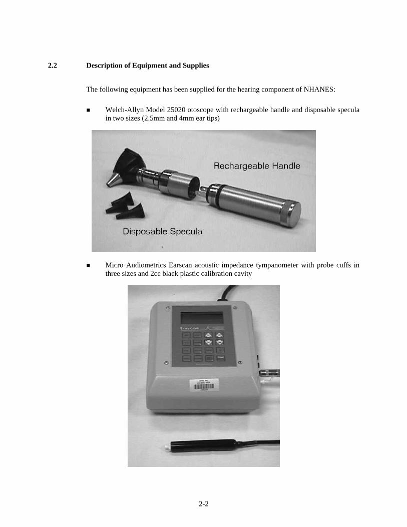
Welch-Allyn Model 25020 otoscope with rechargeable handle and disposable specula
in two sizes (2.5mm and 4mm ear tips)
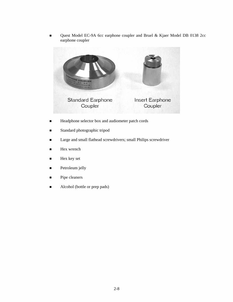
Micro Audiometrics Earscan acoustic impedance tympanometer with probe cuffs in three sizes and 2cc black plastic calibration cavity
2-2

Interacoustics Model AD226 audiometer with power supply and response switch, standard TDH-39P headphones with Phone Guard disposable hygienic covers, and E•A•Rtone 3A insert earphones with disposable foam tips in three sizes and spare plastic connectors
2-3

2-4

Quest Model BA-201-25 bioacoustic simulator and octave band monitor with insert earphone adapters
Quest Model 1800 precision integrating sound level meter and Model OB-300 1/3—1/1 octave filter set
2-5

Quest Model QE 4170 one-inch pressure microphone and microphone adapter ring
Microphone Adapter Ring
Quest preamp with A-63B preamp adapter and 59-733 preamp cable
Preamp with A-63B Adapter
2-6

Quest Model QC-20 calibrator with adapter for ½-inch microphone
Half-Inch Adapter
Quest Model AS-1550 audiometric calibration stand and 500g weight
2-7
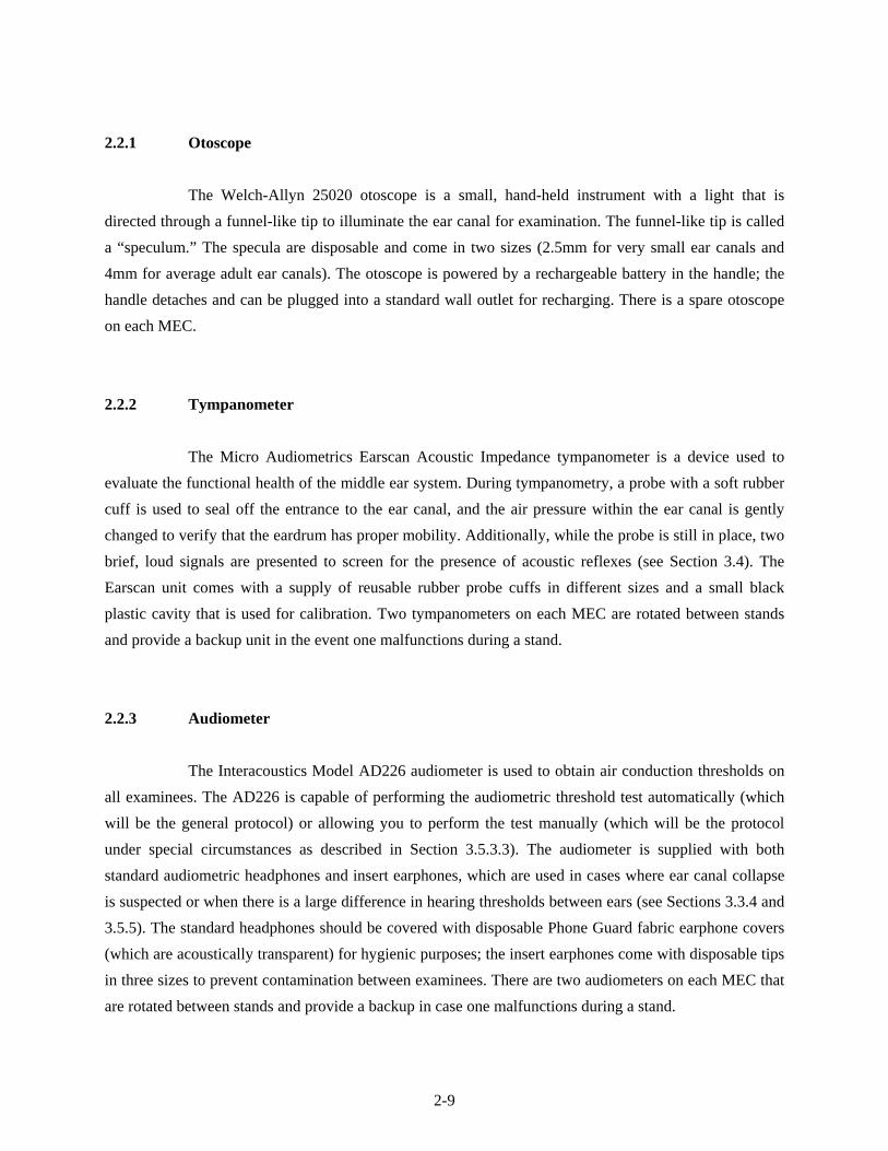
Quest Model EC-9A 6cc earphone coupler and Bruel & Kjaer Model DB 0138 2cc earphone coupler
Headphone selector box and audiometer patch cords
Standard photographic tripod
Large and small flathead screwdrivers; small Philips screwdriver
Hex wrench
Hex key set
Petroleum jelly
Pipe cleaners
Alcohol (bottle or prep pads)
2-8
2.2.1 Otoscope
The Welch-Allyn 25020 otoscope is a small, hand-held instrument with a light that is
directed through a funnel-like tip to illuminate the ear canal for examination. The funnel-like tip is called
a “speculum.” The specula are disposable and come in two sizes (2.5mm for very small ear canals and
4mm for average adult ear canals). The otoscope is powered by a rechargeable battery in the handle; the
handle detaches and can be plugged into a standard wall outlet for recharging. There is a spare otoscope
on each MEC.
2.2.2 Tympanometer
The Micro Audiometrics Earscan Acoustic Impedance tympanometer is a device used to
evaluate the functional health of the middle ear system. During tympanometry, a probe with a soft rubber
cuff is used to seal off the entrance to the ear canal, and the air pressure within the ear canal is gently
changed to verify that the eardrum has proper mobility. Additionally, while the probe is still in place, two
brief, loud signals are presented to screen for the presence of acoustic reflexes (see Section 3.4). The
Earscan unit comes with a supply of reusable rubber probe cuffs in different sizes and a small black
plastic cavity that is used for calibration. Two tympanometers on each MEC are rotated between stands
and provide a backup unit in the event one malfunctions during a stand.
2.2.3 Audiometer
The Interacoustics Model AD226 audiometer is used to obtain air conduction thresholds on
all examinees. The AD226 is capable of performing the audiometric threshold test automatically (which
will be the general protocol) or allowing you to perform the test manually (which will be the protocol
under special circumstances as described in Section 3.5.3.3). The audiometer is supplied with both
standard audiometric headphones and insert earphones, which are used in cases where ear canal collapse
is suspected or when there is a large difference in hearing thresholds between ears (see Sections 3.3.4 and
3.5.5). The standard headphones should be covered with disposable Phone Guard fabric earphone covers
(which are acoustically transparent) for hygienic purposes; the insert earphones come with disposable tips
in three sizes to prevent contamination between examinees. There are two audiometers on each MEC that
are rotated between stands and provide a backup in case one malfunctions during a stand.
2-9

2.2.4 Bioacoustic Simulator
The Quest Model BA-201-25 performs two functions. First, as a bioacoustic simulator, it is a
kind of “dummy” ear that is used to check the calibration of the audiometer on a daily basis. The
simulator is programmed with 60 dB HL thresholds at each test frequency and its “hearing” should be
tested every day to verify that the calibration of the audiometer has not shifted. Special adapters are
provided to allow the simulator to be used with insert earphones as well as with standard headphones.
Second, as an octave band monitor, it continuously measures the background noise levels in the
audiometric test room. Whenever the noise levels in the test room exceed the standards, which have been
programmed into the unit, a light comes on to alert the tester to the problem. Audiometric testing cannot
be accomplished when the monitor indicates that background noise levels are too high (see Section 2.5.1).
There is only one simulator on each MEC. However, there is one additional spare simulator
that is kept in storage at the Westat home office and can be shipped to a MEC if required.
2.2.5 Sound Level Meter and Accessories
The Quest Model 1800 sound level meter and its accessories are used to measure the
intensity, or loudness, of sounds. These instruments will be used throughout the NHANES to measure the
background noise levels in the exam room and to periodically verify the calibration of the audiometer.
The sound level meter uses a 1-inch microphone attached to a preamp, sometimes via the
preamp cable. The Quest Model OB-300 octave filter set is attached to the sound level meter to limit the
instrument to measuring sound levels in a certain frequency range, rather than the overall sound level. The
calibration stand and earphone couplers are used when checking the calibration levels of the audiometer.
The sound level meter is mounted on the photographic tripod when measuring the background noise
levels in the audiometric test room.
Before the sound level meter is used to make any measurement, it must be calibrated with a
known signal to verify that the meter is reading accurately; the Quest Model QC-20 calibrator provides
this known signal.
2-10

There is only one sound level meter kit on each MEC. An additional sound level meter kit is
kept in storage at the Westat home office and will be shipped out on request.
2.2.6 Inventory Procedures
An inventory of the audiometric equipment and supplies will be conducted at the beginning
and the end of each stand, using the form illustrated on pages A-1 and A-2. Please note the following
when conducting the inventory:
Supply counts refer to unused (i.e., spare) items only. Supplies currently in use (for
example, batteries currently in equipment, light bulbs currently in the otoscope, headbands currently attached to headphones) are not to be counted on the inventory sheet.
The “Quick Release Platform” refers to the wheel chair ramp stored along the right side of the sound booth.
Supplies will be sent to a MEC prior to its next stand opening. Malfunctioning or missing equipment
should be reported to the MEC manager and chief health technologist.
2.3 Start of Stand Procedures
2.3.1 Room Setup
Unpack the Quest BA-201-25 bioacoustic simulator and insert a 9-volt battery into the
battery compartment (see Section 2.8.2.1). Mount the simulator on the test room wall, making sure it is
secure on both screws. Insert the microphone cable into the MIC jack at the bottom of the unit. Run the
microphone cable up the wall and across the ceiling through the magnetic hooks and suspend it above the
subject chair. Use a twist-tie to secure the extra cord length; the microphone should be as close to the
ceiling as possible. Insert the black connecting cable for the audiometer into the RESPONSE jack.
Unpack the otoscope and rechargeable handle and plug the handle into a wall outlet. The
handle should be charged for 8 hours before examinations begin at each stand.
2-11

Check the Serial Number Register and unpack the Earscan tympanometer that was NOT
used at the previous stand. Place it on the table inside the sound booth. Plug the power cord into the back
of the unit and into the outlet inside the booth, next to the door. Insert the computer cable into the round
jack next to the power cord on the back of the Earscan (connections to the computer itself will have been
completed by the data manager). Insert the silver plug of the probe assembly into the black jack on the
right side of the Earscan labeled PROBE; then insert the white tip of the air line that extends from the silver
plug into the white jack labeled PROBE.
Check the Serial Number Register and unpack the Interacoustics AD226 audiometer that
was NOT used at the previous stand. Place it on the table outside the sound booth. Insert the black cable
from the power supply into the POWER jack on the back of the audiometer; then plug the power cord into
the power supply and into the wall outlet under the table on the wall of the booth. Connect the computer
cable to the RS232 jack on the back of the audiometer (connections to the computer itself will have been
completed by the data manager). Unpack the headphone selector box and affix it to the Velcro strips near
the jack panel outside the sound booth. Plug the red and blue cables labeled “AUDIOMETER” into the jacks
labeled “RIGHT” and “LEFT,” respectively, on the back of the audiometer (these jacks are also color coded
red and blue). Plug the blue cable from the headphone selector box labeled “STANDARDS” into jack 5 and
the red cable into jack 6 on the sound booth jack panel. Plug the blue cable from the headphone selector
box labeled “INSERTS” into jack 9 and the red cable into jack 10 on the sound booth jack panel. Unpack
the standard headphones and plug the cable with the blue tip into jack 5 and the cable with the red tip into
jack 6 on the jack panel inside the sound booth. Unpack the insert earphones and plug the blue-tipped
cable into jack 9 and the red-tipped cable into jack 10 on the panel inside the booth. Plug the patient
response switch into jack 3 inside the sound booth; plug one end of the black patch cord into jack 3
outside the sound booth and the other end into the “PAT. RESP.” jack on the back of the audiometer.
Cover the unused audio input jacks both inside and outside the sound booth with the protective blue
covers.
NOTE: Actual jack numbers have been assigned arbitrarily. If a jack is broken or if the
equipment will fit more conveniently into a different jack, it is acceptable to use jacks other than those
indicated here. However, each component MUST be plugged into the same numbered jack both
inside and outside the booth. For example, if you decide to use jack 1 for the left standard headphone
cable outside the booth, be sure to plug the left standard headphone cable into jack 1 inside the booth.
2-12

Mount the specula dispenser on the wall and fill it as needed. Unpack the tympanometer
probe cuffs and insert earphone tips and place them in containers on the table inside the sound booth. Fill
the headphone cover dispenser with Phone Guard covers.
2.3.2 Start of Stand Calibrations
Conduct calibration checks of the following equipment in the order indicated (directions for
calibration checks are in Section 2.4, which follows):
Bioacoustic simulator;
Audiometer (acoustic check, simulator check, listening check); and
Tympanometer.
At the start of a stand, one audiometer and one tympanometer should undergo complete
calibration checks. Should one of the units not pass calibration checks, take out the backup unit and
complete the calibration checks on it. Notify the MEC manager of the nonfunctioning unit, so that
arrangements can be made for its repair.
Measure the environmental noise in the audiometric test booth according to the directions in
Section 2.5.2 on page 2-40.
Record the results of start of stand calibrations in the Start of Stand tab in the Integrated
Survey Information System (ISIS) QC application, as explained in the individual calibration instructions
in Section 2.4. The 10 subtabs correspond to the following results:
QC 1: Equipment Serial Numbers
QC 2: Bioacoustic Simulator Calibration Check
QC 3: Audiometer Acoustic Calibration Check (Standard Headphones)
QC 4: Audiometer Acoustic Calibration Check (Insert Headphones)
QC 5: Audiometer Bioacoustic Reference Values (Standard Headphones)
QC 6: Audiometer Bioacoustic Reference Values (Insert Headphones)
2-13
QC 7: Audiometer Listening Check (Standard Headphones)
QC 8: Audiometer Listening Check (Insert Headphones)
QC 9: Environmental Noise Survey
QC 10: Tympanometer Calibration Check
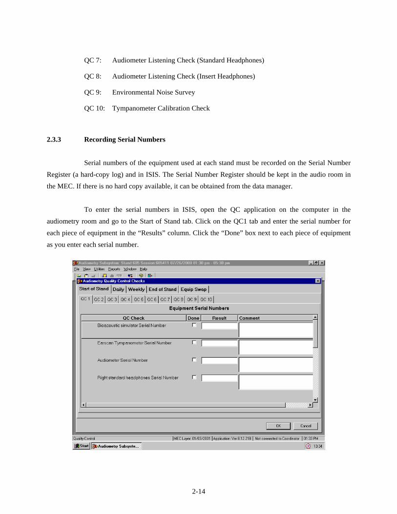
2.3.3 Recording Serial Numbers
Serial numbers of the equipment used at each stand must be recorded on the Serial Number
Register (a hard-copy log) and in ISIS. The Serial Number Register should be kept in the audio room in
the MEC. If there is no hard copy available, it can be obtained from the data manager.
To enter the serial numbers in ISIS, open the QC application on the computer in the
audiometry room and go to the Start of Stand tab. Click on the QC1 tab and enter the serial number for
each piece of equipment in the “Results” column. Click the “Done” box next to each piece of equipment
as you enter each serial number.
2-14

Use the scroll bars to move up and down the screen and enter numbers for all the equipment
listed.
NOTE: Be sure to enter the manufacturer’s serial number for each piece of equipment. Do
NOT enter the DHHS/PHS barcode number or the NHANES equipment identification number. You will
know you are recording the correct number if it has exactly the same number of characters as there are
spaces for that item number on the hard-copy serial number log.
Be certain to enter the serial numbers in the “Results” field and NOT the “Comments” field.
2.4 Calibration Checks
In order for audiometric test results to have any validity, it is necessary to know that all the
equipment associated with the tests was properly calibrated. Calibration checks will therefore be
conducted as the audiometric equipment is set up at the start of each stand, periodically throughout the
stand, and again at the end of each stand to ensure that the accuracy has not shifted.
2.4.1 Bioacoustic Simulator Calibration Check
Before the Quest BA-201-25 bioacoustic simulator can be used to verify the calibration of
the audiometer, its own accuracy must be verified. This is done by testing the same headphone on both
the right and left “ears” of the simulator. Because the test circuits on each side are identical, testing each
of them with the same headphone should result in the same threshold values. The calibration of the
bioacoustic simulator is checked at the beginning and end of each stand. It must be checked before it is
used to check the calibration of the audiometer.
Conduct the calibration check of the bioacoustic simulator in the following way:
Turn on the audiometer and allow it to warm up for at least 3 minutes.
Press the ON button on the Quest BA-201-25 bioacoustic simulator and check the power indicator to verify that the light is flashing (if the light is flashing dimly or does not flash at all, replace the battery as described in Section 2.8.2.1). Unplug the response switch for the audiometer from jack 3 inside the sound booth, and plug the
2-15

Verify that the audiometer is set as follows:
- MAN REV button set to REV
- 1 5 DB button set to 5
- RIGHT ear selected
- Standard HEADSET selected (on the audiometer and the headphone switchbox)
NOTE: Pulsing should be off (i.e., both lights off on the PULSE button) during this calibration.
Set the frequency to 500 Hz and the intensity level to 30 dB.
Close the doors to the sound booth and the audiometric test room.
Slowly turn the left DB HL knob on the audiometer to increase the intensity in 5 dB steps. Pause a few seconds at each new intensity level and check to see if the right light on the simulator becomes illuminated (the response light on the audiometer should light up at the same time). Once the right light is lit, stop increasing the intensity and press STORE to record this level in the audiometer.
The audiometer will automatically advance to the next frequency (1,000 Hz). Reduce the intensity to 30 dB and repeat the slow increase in level until the right light on the simulator becomes lit again. Press STORE to record this value. The audiometer will again advance to the next frequency. Continue this procedure (slowly increasing intensity from 30 dB until the right light on the simulator becomes lit) for the remaining test frequencies in the right ear only, storing the values in the audiometer.
When all frequencies have been tested in the right earphone, capture the data in ISIS. Go to the QC2 tab (under Start of Stand QC) and click on the “Capture R/R” button to capture the QC data for the right coupler.
NOTE: If you would like to display the data on the audiometer, press SHIFT/EXT range to display threshold results. The display should appear as shown below:
PH-R *** *** 65 *** 65 *** 65 65 65 65 65
2-16

Reverse the headphones on the simulator, such that the left earphone is over the simulator coupler marked right and the right earphone is on the simulator coupler marked left. Press SHIFT/DEL on the audiometer and hold the buttons down until the display reads that “All thresholds are del.” Verify that the other audiometer settings are still as noted above, and repeat the procedure. The audiometer should still be set to test the right ear; however, this time you will be observing the left light on the simulator. When all frequencies have again been tested and stored in the audiometer, click on the “Capture R/L” button to capture the QC data for the left coupler.
ISIS will automatically compare both sets of threshold values (i.e., obtained from the same
earphone over the right versus the left couplers on the simulator). The thresholds must agree within ±5
dB. If the thresholds at any frequency differ by more than 5 dB, ISIS will display an error message.
Notify the MEC manager and chief technologist before continuing with any further calibration checks.
2-17

2.4.2 Audiometer Calibration Checks
There are three levels of checks on the audiometer calibration. An acoustic calibration check
involves using a sound level meter to measure the test signals produced by the audiometer and verifying
that these signals meet standard specifications. A bioacoustic check involves using a bioacoustic
simulator to monitor the output of the audiometric headphones in order to verify that the output remains
stable over time. A functional check involves listening to the output through the headphones to ensure
that the signals are being routed properly and that there are no extraneous sounds. In addition to these
calibration checks, all audiometers will be sent to a laboratory for an exhaustive calibration once a year,
or whenever unresolvable problems are discovered during the calibration checks.
2.4.2.1 Acoustic Calibration Check
There are two components to an acoustic calibration check—verifying output (which
involves measuring each test frequency at one intensity level) and verifying linearity (which involves
measuring multiple intensity levels at one frequency). To check the output, the audiometer is set to
produce a 70 dB tone at each frequency, and the sound level meter is used to make sure the output is
actually 70 dB. To check the linearity, the hearing level dial is adjusted in 10 dB steps, and the sound
level meter is used to verify that the output actually changes by 10 dB. The right and left earphones of
both the standard and insert headphones must be checked individually. This must be accomplished at the
beginning and end of each stand.
An acoustic calibration check is a very exact procedure and must be done thoroughly and
carefully to ensure valid results. Conduct the calibration check in the following way:
Turn on the audiometer and let it warm up for at least 3 minutes.
Set up the sound level meter and octave band filter.
- Insert batteries (if necessary) into the sound level meter and the octave filter set, as described in Section 2.8.1.2.
2-18

- Connect one end of the preamp cable to the top of the sound level meter and tighten the silver screw. The meter should appear as shown below:
Assemble the audiometer calibration system. Refer to the diagram below and step-by-step instructions and photographs that follow.
- Connect the stand tower to the stand plate with the locking screw.
2-19

- Verify that the other end of the preamp cable is attached to the adapter ring. The assembly should appear as shown below. (Because it is difficult to insert the preamp cable through the adapter ring, these two items generally remain connected. If they are not, it may be necessary to lubricate the cable and/or ring with a small amount of petroleum jelly in order to connect the two components.)
- Connect the preamp to the preamp cable just above the adapter ring. Gently screw the one-inch microphone onto the top of the preamp and A-63B adapter.
2-20

- Firmly press the adapter ring into the stand tower, allowing the preamp cable to exit one of the tower slots. The calibration system should now appear as shown below:
Slide the POWER switch in the lower right of the meter to on.
Press the battery button on the sound level meter to check the batteries. Good batteries are indicated by a bar extending to the right well beyond the bat arrow (5 on the numeric scale). If the bar falls near or below the indicating arrow, both batteries must be replaced before proceeding (see Section 2.8.1.2).
Calibrate the sound level meter:
- Set the sound level meter controls as follows:
RESPONSE: SLOW
WEIGHTING: LIN
MODE: SPL
RANGE: 60-120
NOTE: Be sure that the POWER switch on the OB-300 filter set is off.
- Set the calibrator to 1 KHz and 94 dB. Slide the calibrator over the microphone so that it fits snugly. Turn on the calibrator.
2-21

- Check the meter display. It should read 94.0 dB. If it does not, use the small flathead screwdriver to adjust the small control on the left side of the meter until the proper value is displayed (see photograph below).
NOTE: Turn the screwdriver up (i.e., away from you) to adjust the meter down; turn the screwdriver down (i.e., toward you) to adjust the meter higher.
- Remove the calibrator and turn it off. Replace the ½-inch adapter.
2-22

Attach the appropriate coupler to the calibration assembly.
- For standard headphones: Pull the black microphone adapter ring over the microphone until it is fully seated. DO NOT PUSH THE ADAPTER ONTO THE
MICROPHONE WITH THE PALM OF YOUR HAND BECAUSE THE PRESSURE
BUILDUP WILL DAMAGE THE MICROPHONE. Slide the EC-9A coupler over the adapter. See pictures below for reference.
2-23

- For insert earphones: Carefully unscrew the metal grille on top of the microphone and remove it. Very carefully slide the DB 0138 (HA-2) 2cc coupler over the bare microphone and screw it in place. Be very careful not to touch the top (i.e., the diaphragm) of the microphone! Refer to the photographs below for guidance:
2-24

Mount the earphone to be tested onto the coupler:
- For standard headphones: Remove the earphones from the headband (use a large flathead screwdriver to gently lift the silver clip off each earphone). Place the earphone squarely over the top of the coupler. Place the W-440 weight on top of the earphone to hold it in place. Both the weight and the earphone should be centered as accurately as possible on the coupler. In addition, the two sides of the weight should be in direct contact with the sides of the coupler. See illustration below:
2-25

- For insert earphones: Slide the white plastic tip at the end of the sound tube into the black plastic tubing on the tip of the coupler (a foam eartip is not used during this calibration check). Make certain that the tip is inserted all the way to the nub. Hang the earphones in such a way that there are no kinks in the sound tubing (e.g., upside down from the headphone hook in the sound booth).
Check the pure tone output levels of the audiometer at each frequency through the earphone under test:
- Set the DB RANGE on the sound level meter to 40-100.
- Set the POWER switch on the OB-300 octave filter set to MANUAL and set the MODE switch to 1/1.
2-26

- Set the audiometer controls as follows:
MAN REV button set to REV
1 5 DB button set to 5
RIGHT or LEFT ear selected, as appropriate
Appropriate HEADSET selected (on the audiometer and switchbox)
Left attenuator (i.e., the left DB HL knob) adjusted to 70 dB HL
NOTE: Pulsing should be off (i.e., both lights off on the PULSE button) during the acoustic calibration check.
- Set the test frequency on the audiometer to 500 Hz (using the FREQUENCY DECR button) and use the button on the octave filter to select 500.
- Press the RESET button, then the RUN button on the sound level meter. Allow the meter to measure for about 5 seconds (the reading should become very stable), then record the measurement on the calibration log sheet in the section labeled “Output Check.” This measure will be copied into ISIS from the calibration log sheet.
- Set the test frequency on the audiometer to 1,000 Hz (using the FREQUENCY
INCR button) and press the button on the octave filter to set it to 1k. Press RESET (do NOT press RUN), repeat the measurement process, and record the result on the calibration log.
- Continue measuring the audiometer output at all test frequencies. Refer to the table below for appropriate frequency settings on the audiometer (AD226) and the octave filter (Oct Fil). Remember to press RESET before making the measurement at a new frequency! Record the calibration values on the log sheet. Calibration values measured on the sound level meter should match the reference values in the table, within the tolerances shown:
REFERENCE CALIBRATION LEVELS FOR PURE TONES
Frequency Setting Standard Headphones Insert Earphones
AD226 Oct Fil Reference Level Tolerance Reference Level Tolerance
500 500 81.5 78.5 84.5 75.5 72.5 78.5
1000 1k 77.0 74.0 80.0 70.0 67.0 73.0
2000 2k 79.0 76.0 82.0 73.0 70.0 76.0
3000 4k 79.3 76.3 82.3 72.8 69.8 75.8
4000 4k 79.5 76.5 82.5 75.5 72.5 78.5
6000 8k 84.8 79.8 89.8 71.3 66.3 76.3
8000 8k 83.0 78.0 88.0 70.0 65.0 75.0
2-27

Check the linearity of the pure tone attenuator (i.e., the left DB HL knob) through the earphone under test:
- With the earphone still in place, reset the test frequency on the audiometer to 1,000 Hz and reset the octave filter to 1k.
- Adjust the left attenuator on the audiometer to 70 dB HL.
- Press RESET and verify that the sound level meter display still reads “RUN.” Allow the sound level meter to measure for a few seconds (the reading should become very stable). Enter the measurement onto the calibration log in the section labeled “Linearity Check.”
- Reduce the attenuator to 60 dB HL. Press RESET and allow the meter to measure as before. Record the value on the calibration log.
- Repeat again with the attenuator set to 50 dB HL.
- Set the DB RANGE selector on the sound level meter to 20-80. Continue making measurements in 10 dB decrements through 10 dB HL (or until the sound level meter no longer responds) and record the values on the calibration log. Remember to press RESET before making the measurement at a new intensity! Calibration values measured on the sound level meter should shift between 9 and 11 dB with each 10-dB reduction in intensity.
NOTE: It may not be possible to obtain an accurate sound level at 10 dB HL due to the noise floor of the equipment and surrounding environment. Do not be concerned if the sound level meter reading at 10 dB HL is not within calibration limits.
- Press MAN REV on the audiometer to turn off the pure tone signal.
Repeat the output and linearity checks for each ear of each headphone.
Enter the results of the acoustic calibration check into ISIS. To enter the standard headphone
data, go to the QC3 tab under the Start of Stand tab (the insert headphone data will be entered under the
QC4 tab). Type the data from the log sheet for the output checks into the corresponding frequency boxes.
Do the same for the linearity check data, and enter the numbers into the corresponding intensity boxes. Be
sure to use the correct ISIS tab for each headphone (standard or insert).
2-28

If any results are out of range, ISIS will display a notification message. Repeat the
measurements. If results remain out of range, notify the MEC manager and chief health technologist
before proceeding with further calibration checks.
NOTE: Audiometers and headphones are calibrated as a unit. If a set of headphones is
replaced at any point during the stand, the acoustic calibration must be repeated and new bioacoustic
simulator reference values must be obtained.
2.4.2.2 Audiometer Bioacoustic Check
The bioacoustic check serves to confirm that the audiometer is remaining within the limits of
calibration. This is done by testing someone (or something) with known hearing thresholds and verifying
that the thresholds remain constant across time. The bioacoustic simulator serves as that “something” with
known hearing levels. The simulator is programmed with a reference audiogram, which should remain
unchanged as long as the calibration of the audiometer does not shift. The “hearing” of the simulator is
tested at the beginning of each stand (following the acoustic calibration check) to obtain the reference
2-29
thresholds. Then, the simulator is retested each day throughout the stand and again at the end of the stand.
The results of these retests are compared with the reference thresholds to verify that there has been no
shift.
The Quest BA-201-25 bioacoustic simulator is used to monitor the calibration of the right
and left earphones of both the standard and insert headsets.
At the beginning of the stand, determine the reference values for each ear of each headphone
in the following way:
Turn on the audiometer and allow it to warm up for at least 3 minutes.
Press ON to turn on the bioacoustic simulator. Verify that the power is flashing brightly, indicating that the battery voltage is sufficient. (If the power light does not flash or flashes dimly, change the battery as explained in Section 2.8.2.1.)
If necessary, unplug the audiometer response switch from jack 3 inside the test room, and plug the response cable from the simulator into this jack.
Verify that standard headphones are selected on the headphone selection box.
Place the standard headphones squarely on the simulator with the headband height fully extended; make certain that the right earphone is on the right coupler and the left earphone is on the left coupler.
Set the following controls on the audiometer:
- MAN REV button set to REV
- 1 5 DB button set to 5
- RIGHT ear selected
- Standard HEADSET selected (on the audiometer and the switchbox)
- Set the frequency to 500 Hz and the intensity level to 30 dB.
NOTE: Pulsing should be off (i.e., both lights off on the PULSE button) when conducting calibration checks using the bioacoustic simulator.
Close the doors to the sound booth and the audiometric test room.
2-30

Slowly turn the left DB HL knob on the audiometer to increase the intensity in 5 dB steps. Pause a few seconds at each new intensity level and check to see if the right light on the simulator becomes illuminated (the response light on the audiometer should light up at the same time). Once the right light is lit, stop increasing the intensity and press STORE to record this level in the audiometer.
The audiometer will automatically advance to the next frequency (1,000 Hz). Reduce the intensity to 30 dB and repeat the slow increase in level until the right light on the simulator becomes lit again. Press STORE to record this value. The audiometer will again advance to the next frequency. Continue this procedure (slowly increasing intensity from 30 dB until the right light on the simulator becomes lit) for the remaining test frequencies, storing the values in the audiometer.
Repeat the procedure for the left headphone.
When all frequencies have been tested in both ears, press SHIFT/EXT RANGE to display threshold results. The display should appear as shown below:
PH-R *** *** 65 *** 65 *** 65 65 65 65 65
- The first value displayed is the 500 Hz threshold; the second value is the 1,000 Hz threshold, and so on. (Ignore the asterisks; these represent frequencies of 125, 250, 750, and 1500 Hz, which are not being tested in NHANES.) Press RIGHT or LEFT to toggle between results for the right and left headphone as necessary. These thresholds will be the reference thresholds for the daily bioacoustic simulator calibration of the standard headphones throughout the stand.
Copy the results into the reference values section of the Daily Audiometer Bioacoustic Check log form labeled “Standard Headphones.” Even though these results will also be stored in ISIS, it is convenient to have a hard copy for easy reference should there be difficulties encountered during daily calibration checks during the stand.
Enter the standard headphone QC data into ISIS. Go to the QC5 tab under the Start of Stand tab and click on the “Capture” button to bring the data from the audiometer into ISIS.
- Data that are entered during the daily QC checks will be automatically compared to these reference values established at the start of the stand.
2-31

Remove the standard headphones from the simulator. Gently press the black insert earphone adapters into the couplers on each side of the simulator.
Place E-A-RLink 3A eartips (the standard or middle size) onto the ends of the insert earphones. Firmly roll each tip between your fingers to compress the foam and slide the tip into the opening on the adapters. Hold the tip in place until the foam expands. (Drape the Velcro strip across the top of the simulator to prevent the weight of the earphones from pulling the tips out of the adapters.)
Press SHIFT/RIGHT to change the headphone selection to “Inserts.” Switch the headphone selector box to inserts.
Press SHIFT/DEL on the audiometer until the display reads that “All thresholds are del.” Verify that the other audiometer settings are still as noted above.
Conduct the threshold search in each ear at each frequency as before, storing the thresholds in the audiometer.
When the test is complete, press SHIFT/EXT RANGE to display threshold results. Copy the results into the reference values section of the Daily Audiometer Bioacoustic Check log form labeled “Insert Earphones.”
2-32
Enter the results into ISIS by going to the QC6 tab and clicking the “Capture” button. These thresholds will be the reference thresholds for the daily bioacoustic simulator calibration of the insert earphones throughout the stand.
Unplug the simulator response cable from jack 3 inside the test room, and plug the cable for the audiometer response switch back into this jack.
The daily calibration check is conducted in the same way. Standard and insert headphones
will be checked on alternate days; ISIS will prompt you regarding which headphones to check on a
particular day. Enter the results into ISIS under the Daily section; tab “Audio Bioacoustic Check.” ISIS
will compare the results of the Daily QC to the reference values obtained at the Start of Stand QC. If the
daily results differ from the start of stand reference values by more than +/- 5dB, ISIS will display a
notification message. The MEC manager and the chief technologist must be notified of the problem
before any more exams are conducted.
At the end of the stand, conduct a final bioacoustic calibration check of both sets of
headphones. Enter the QC data from the end of the stand in the End of Stand section, tab QC5 for
standard headphones, and tab QC6 for inserts. ISIS will compare the results with the reference values and
display a notification message if the values differ by more than +/-5 dB. If the end of stand calibration is
off, notify the MEC manager and the chief technologist.
2.4.2.3 Audiometer Listening Check
The object of the listening check (also called a functional check) of the audiometer is to
verify that the unit is functioning properly and that the test signals are being generated and routed to the
appropriate earphone without distortion, extraneous sounds (such as clicks or hum), or loss of signal. A
listening check is conducted at the beginning of each stand for both standard and insert headphones.
Throughout the stand, standard and insert headphones are checked on alternate days following the same
schedule as for the bioacoustic check. ISIS will prompt you regarding which headphones to check on a
particular day. A listening check of both sets of headphones is conducted again at the end of each stand.
NOTE: Technologists must have normal hearing (i.e., thresholds better than or equal to 25
dB HL from 500-8000 Hz bilaterally) to conduct the audiometer listening check.
2-33

There are five components to the functional check—listening to the quality of the test tones;
verifying the adjustment of the attenuator; checking the integrity of the earphone cords; checking the
function of the response switch; and ensuring the proper routing of signals between the right and left
earphones. The listening check is conducted as described below.
Turn on the audiometer and allow it to warm up for at least 3 minutes.
Verify that the appropriate headphones are selected on the headphone selector box.
Set the following controls on the audiometer:
- MAN REV button set to REV
- PULSE button set to ___
- 1 5 DB button set to 5
- RIGHT ear selected
- Appropriate HEADSET selected
Check tonal quality:
- Set the frequency to 500 Hz and adjust the left attenuator (i.e., the left HL DB knob) to a level of 50 dB HL. Listen to the tone pulses; verify that the tones are clear and that there is no noticeable click at the beginning or end of each pulse.
- Cycle through all test frequencies by pressing the FREQUENCY INCR button, listening briefly (about three pulses) to each to verify that the tones are not distorted and that there are no extraneous sounds.
- Select the LEFT headphone, readjust the left attenuator to a level of 50 dB HL, and repeat the procedure.
Check the accuracy of the attenuator control:
- Select a test frequency of 1,000 Hz and adjust the left attenuator to 0 dB.
- Adjust the left attenuator slowly in 5 dB steps up to 70 dB HL, stopping briefly at each level to verify the intensity change and listening for any extraneous sounds (clicks, scratches, etc.) as the level is changed.
NOTE: It is only necessary to conduct the attenuator check in one ear.
2-34

Check the earphone cords:
- Select a test frequency of 1,000 Hz and adjust the left attenuator to 50 dB HL. Press the PULSE button once to turn off the pulsing (there should now be a steady tone).
- Wiggle the earphone cords, especially where they enter the headphones and where they are plugged into the jacks inside the test room. Also wiggle the patch cords between the headphone box and the audiometer. Listen for any interruption in the test signal, changes in the signal level or static or other noise in the headphones as the cords are flexed.
- Select the LEFT headphone, readjust the intensity to 50 dB HL, and repeat the procedure.
Check the response switch:
- Press MAN REV once to turn off the test signal.
- Press the response button. Verify that the response light on the audiometer is activated as the button is pressed and that pressing the response switch does not produce any sound in the earphones.
Check for crossover:
- Press MAN REV to turn on the test signal.
- Select the RIGHT headphone, adjust the left attenuator dial to 70 dB HL, and set the test frequency to 1,000 Hz; you should hear a loud signal in the right headphone.
- Unplug the right earphone jack from the back of the audiometer. Listen through the headphones; there should be no signal in either ear.
- Plug the right earphone jack back into the audiometer.
- Select the LEFT headphone and readjust the left attenuator dial to 70 dB HL. There should be a loud signal in the left ear.
- Unplug the left headphone jack from the back of the audiometer. Listen through the headphones; there should be no signal in either ear.
- Plug the left earphone jack back into the audiometer.
- Press MAN REV to turn off the test tone.
2-35

Enter the results of the Audiometer Listening Check in ISIS as either “Pass” or “Fail” under
tab QC7 for standard headphones and tab QC8 for inserts in the Start of Stand section. If any problems
are noted, explain the problems in the “Comments” box and notify the MEC manager and the chief health
technologist. A sample of the Audiometer Listening Check screen for Standard Phones is below:
2.4.3 Tympanometer Calibration Check
Two measures require calibration on the Earscan units: air pressure and physical volume.
These measures must be calibrated every day, including the beginning and end of stand as well as each
day throughout the stand. In addition, if there is a loss of power during a session, or if the Earscan is
turned off between sessions, the calibration should be rechecked once the power is restored.
Air pressure is automatically calibrated to zero each time the Earscan is turned on. The air
pressure calibration will be affected by changes in temperature, so make sure that the temperature of the
unit has stabilized prior to turning on the unit.
2-36

Physical volume is calibrated in the following way:
Turn the Earscan on and wait for the display screen to read “Make Selection Output to
Computer.”
NOTE: If the display reads “Output to Printer” rather than “Output to Computer,” press SPEC, then DATA; the display should change to “Output to Computer.” This change should be stored in memory even after the unit is turned off.
Insert the probe tip (with no ear cuff) into the black calibration cavity, as shown below:
Press the CAL key. Earscan will automatically run an immittance test; the screen will display the message “calibrating.”
NOTE: If the CAL key is pressed before the probe is placed in the calibration cavity, Earscan will not run the calibration test.
Wait for the unit to run the test. When the test is complete, the screen will read “remove probe.” Remove the probe from the calibration cavity.
Press ENTER, then DATA on the Earscan unit. The display will read “Busy” for a few seconds while the data are transferred.
Go to the QC10 tab under the Start of Stand tab. Click the “Capture” button to capture the tympanometry QC data.
2-37

NOTE: If you wish to display the results on the Earscan unit, press DISP. The screen will
display numeric tympanometry results. The physical volume measurement is shown opposite the notation
“PV.”
The PV measurement must be within the range 1.8-2.1 ml. Other tympanometry results (e.g.,
middle ear pressure [MEP] and compliance [COMP]) will be displayed on the Earscan screen but are not
captured by ISIS, as only the PV value is relevant to this calibration.
If the physical volume measurement does not fall within the required range, ISIS will display
a notification message. Repeat the calibration making sure to hold the probe very still (ambient movement
results in “noisy” immittance measurements). Placing the probe on a piece of foam or other soft surface
during the calibration may be helpful. If the physical volume is still out of calibration limits, clean and
reseal the probe tip as described in Section 2.8.4.2. If this fails to correct the problem, notify the MEC
manager and chief technologist.
NOTE: Each Earscan unit and its probe are calibrated as a unit (the probe has the serial
number of the appropriate Earscan scratched onto the silver plug). If a tympanometer malfunctions during
a stand, both the Earscan unit and the probe must be replaced.
2-38

2.4.4 Troubleshooting Calibration Problems
The following problems may be encountered during audiometric calibration checks.
Potential solutions are listed for each problem to assist in troubleshooting these difficulties.
Tympanometer PV value outside range:
- Repeat calibration holding probe very still or placing it on a piece of soft foam.
- Clean probe tip and reseal with petroleum jelly, as explained in Section 2.8.4.2.
Audiometer acoustic calibration values out of range:
- Make sure audiometer is set to proper headset.
- Make sure octave-band filter is set to the appropriate frequency.
- Verify that you are comparing results to the appropriate set of reference values (i.e., for standard or insert headphones).
- Check the batteries in the sound level meter.
- Verify that all headphone jacks are plugged in completely.
- Reclean the audio jacks by moistening the headphone jacks with alcohol from an alcohol wipe and inserting/removing the jack in and out of the panel several times, twisting it around a bit in the jack panel each time.
- Place calibration stand on a piece of soft foam to avoid influence of low-frequency vibration.
Sound level meter reads “– – –”:
- Verify that DB RANGE setting is correct.
- Press RUN.
- Check batteries.
Audiometer bioacoustic calibration is more than 5 dB from reference values:
- Check battery in bioacoustic simulator.
- Verify that audiometer is set to appropriate headphones (standard or insert).
- Make sure you are comparing results to the appropriate reference values (standard or insert).
2-39

- (For standard headphones) make sure insert earphone adapters were removed from the simulator.
2.5 Environmental Noise Survey
2.5.1 Environmental Noise Principles
In order to obtain valid hearing threshold measurements, the background noise levels in the
test environment (called the ambient noise) must be quiet enough for the examinee to hear the very low
intensity test tones that will be presented to him or her. If the ambient noise is too high, then the examinee
might be unable to hear signals that his auditory system is capable of sensing, simply because the test
environment is inadequate.
Because the sound room used in NHANES is mobile, the ambient noise levels must be
checked each time the MEC is moved to a new location. Therefore, a sound survey must be done as part
of the setup procedures at the beginning of a new stand. Additionally, since the sound environment
around the MEC is subject to change, the sound survey will be repeated weekly during the stand to verify
that the ambient noise has not changed. Finally, if at any point you notice a change in the background
environment (for example, if any of the background noise indicators on the bioacoustic simulator light up
or if operations using heavy equipment begin adjacent to the MEC), the survey must be repeated to check
for any problems that would interfere with accurate testing.
2.5.2 Environmental Noise Survey Procedure
The background noise levels in the sound room should be measured insofar as possible
under the same conditions as will exist during actual audiometric testing. Therefore, prior to conducting
the ambient noise survey, set up the test environment as follows:
Computer, audiometer, and tympanometer turned on;
Lights turned on inside the booth; lights turned off outside the booth;
Ventilation system turned on inside the test booth; and
Sound room and hallway doors closed.
2-40

Conduct the environmental noise survey in the following way:
Set up the sound level meter and octave filter set
- Connect the preamp directly to the top of the sound level meter. Gently screw the 1-inch microphone onto the top of the preamp and A-63B adapter. The meter should appear as shown below:
- Mount the sound level meter on the tripod and adjust it to a 45-degree angle
(pointing toward the ceiling). Place the sound level meter in the test room at the approximate position the examinee’s head will occupy during testing. Position the tripod so that the meter display is visible through the window in the sound booth door.
Slide the POWER switch of the sound level meter to “on” and check the batteries, as described in Section 2.4.2.1.
Set the sound level meter controls as follows:
- Response: Slow
- Weighting: Lin
- Mode: SPL
- Range: 60-120
Be sure that the power switch on the OB-300 filter set is off.
Calibrate the sound level meter as described in Section 2.4.2.1
NOTE: Even if the sound level meter was calibrated previously in order to check the acoustic calibration of the audiometer, it must be calibrated again here because the preamp cable is no longer being used.
Reset the sound level meter range to 20-80.
2-41

Reset the sound level meter mode to LEQ.
Set the POWER switch on the OB-300 octave filter set to manual and set the mode switch to 1/1.
Use the button on the octave filter to select a center frequency of 63 Hz. Slide the POWER switch on the octave filter to AUTO. Press the button, then RUN.
Exit the sound booth and close the sound booth door. Wait for the octave filter to advance to a center frequency of 125 Hz. The meter will average the sound level for approximately 25 seconds before advancing to the next frequency. Record the average level on the environmental noise survey log form.
NOTE: An ambient noise measurement is not recorded at 63 Hz. The octave filter is initially set for this frequency to allow time for you to exit the room and close the door before beginning measurements at 125 Hz.
The octave filter will automatically advance to a center frequency of 250 Hz (the display will read ――― as the frequency changes). The meter will repeat the measurement process, averaging the background noise at 250 Hz. Record the result on the calibration log.
Continue measuring in the same way as the octave filter automatically advances to each successive frequency band. Record average background noise levels at 500, 1k, 2k, 4k, and 8k Hz.
Open the door to the sound room. Slide the POWER switches on both the sound level meter and octave filter set to “off.”
Copy the data from the environmental noise survey log into the Start of Stand QC section
under tab QC9. The QC screen displays the maximum limits for the ambient noise levels:
2-42

If the noise levels are too high at any frequency, ISIS will display a notification message.
Try to determine the source of the interfering sound and correct it. If it is not possible to reduce the
ambient noise to acceptable levels, inform the MEC manager immediately. Pure tone audiometric
testing can NEVER be done when the ambient noise levels in the test room exceed the levels shown
on the screen above. Thresholds obtained in high background noise are invalid and useless.
2.5.3 Daily Monitoring of Ambient Noise Levels
The Quest BA-201-25 is equipped with an octave band monitor that monitors the ambient
noise in the sound room continuously. The octave band monitor is activated simply by turning on the
simulator. If the background noise levels exceed the maximum levels that have been programmed into the
unit, one or more of the red indicators will light up.
Whenever pure tone testing is conducted, the monitor should be observed. If the indicator
lights remain on for more than a few seconds, the hearing test should be suspended until the noise
problem is resolved.
2-43
2.6 Daily Procedures
2.6.1 Set Up and Calibration
Turn on the audiometer and tympanometer and allow them to warm up for at least
10 minutes prior to beginning the daily calibration procedures. Unplug the otoscope base from the electric
outlet and screw the top portion onto it. Turn on the otoscope and verify that it works. Turn on the
ventilation switch inside the sound booth and open the door. Keep the door to the booth open as often as
possible to keep the temperature inside at a comfortable level.
Calibrate the air pressure and physical volume measurements on the tympanometer as
described in Section 2.4.3. Remember that the air pressure calibration—while automatic—will be affected
by changes in temperature; if a large change in temperature occurs in the test room over the course of the
day, turn the power off, wait 3 seconds, and turn the unit on again. Also, if the Earscan is turned off at any
point during the day (e.g., between sessions or due to a power outage), recheck the physical volume
calibration before conducting the next exam.
Conduct a bioacoustic check and a listening check of the headphones, as described in
Sections 2.4.2.2 and 2.4.2.3. Standard and insert headphones should be checked on alternate days, as
prompted by ISIS.
2.6.2 Changing Equipment After Start of Stand
If equipment is changed for any reason during a stand, the replacement equipment must go
through the start of stand calibration procedures. All calibration checks done on replacement equipment
will be entered into ISIS under the Equip Swap section. The QC tabs in the Equip Swap section are
identical to the tabs in the Start of Stand section. The serial number of the new piece of equipment must
be entered on the hard-copy serial number log and in the QC1 tab ISIS. Appropriate calibration checks
must be conducted as indicated below.
2-44

If the bioacoustic simulator is swapped, conduct the following QC checks:
QC 1: Enter the serial number of the replacement bioacoustic simulator.
QC 2: Check the calibration of the replacement bioacoustic simulator.
QC 5: Obtain new reference values for the standard earphones.
QC 6: Obtain new reference values for the insert earphones.
If the tympanometer is changed, conduct the following calibration checks:
QC 1: Enter the serial number of the replacement tympanometer.
QC 10: Calibrate the replacement tympanometer.
If the audiometer is swapped, conduct the following calibration checks:
QC 1: Enter the serial numbers of the replacement audiometer, right and left standard
earphones, and right and left insert earphones.
QC 3: Conduct complete acoustic calibration check of the standard earphones.
QC 4: Conduct complete acoustic calibration check of the insert earphones.
QC 5: Obtain new reference values for the standard earphones.
QC 6: Obtain new reference values for the insert earphones.
QC 7: Do a listening check of the standard earphones.
QC 8: Do a listening check of the insert earphones.
If the sound level meter kit (or any part of it) is changed, record the following QC:
QC 1: Enter serial numbers of the replacement sound level meter, octave-band filter set,
calibrator, and microphone.
NOTE: If equipment is changed at the beginning of a test day, you may need to enter the
results into the daily QC section as well.
2-45

2.6.3 Procedures at the End of an Exam Day
At the end of each test day, recharge the otoscope as explained in Section 2.8.3.2. Clean the
immittance probe cuffs as described in Section 2.8.4.1 and leave them to dry overnight. Turn off all the
audiometric equipment.
NOTE: Do not recharge the otoscope if the MEC will be closed the following day.
2.7 Weekly Procedures
Conduct an environmental noise survey according to the procedure given in Section 2.5.2.
Clean the viewing window on the otoscope as described in Section 2.8.3.3, and the immittance probe tip
as described in Section 2.8.4.2.
2.8 Equipment Care and Maintenance Procedures
2.8.1 Sound Level Meter and Accessories
2.8.1.1 General Handling
Sound level meters are very precise instruments that require careful handling. Always use
the following precautions when handling the sound level meter and its accessories:
Handle the microphone very carefully. Never touch the diaphragm of the microphone;
try to keep dust and other objects from touching the diaphragm as well.
Store the microphone in its case when it is not in use. Do not leave the microphone attached to the preamp.
Make sure the power is turned off on the sound level meter and octave filter set before assembling or disassembling the meter. Especially, NEVER attach the microphone to the sound level meter when the power is on.
Attach the microphone, preamp, adapters, couplers, etc., very gently. Never try to force a connection. If something does not seem to be attaching easily, remove it and try again.
2-46

Do not expose the sound level meter or its accessories to excessive heat, cold, or dampness. Allow the instruments to adjust to the ambient temperature of the environment before using them.
Make sure the batteries are in good condition. If the meter will be in storage for an extended period of time (more than a week; e.g., between stands), remove the batteries from the meter and the filter set before storing them away.
2.8.1.2 Changing Batteries
The sound level meter and octave filter set together require two 9-volt alkaline batteries. The
batteries go into the battery compartment underneath the instrument. Use a small Philips head screwdriver
to remove the cover plate. Snap the batteries onto the connectors inside the compartment. Replace the
cover and screw it back into place. Battery life is approximately 8 hours when both the meter and the
octave filter set are used.
The QC-20 calibrator requires one 9-volt alkaline battery. When the battery is so low that it
would affect calibration, the LOBAT indicator will light up and the calibrator will produce no sound. To
2-47

replace the battery, gently unscrew the gray section of the calibrator from the black section and slide the
gray cover off (see illustration below). Unsnap the battery from its connector. Press the flat end of the
new battery down on the foam pad until it fits underneath the connector; then snap the battery into place.
Slide the calibrator back into the gray sleeve and screw it into place.
Changing the Battery in the Calibrator
2.8.1.3 Annual Calibration
The sound level meter, octave filter set, and microphone should receive a comprehensive
calibration annually (or sooner if problems are encountered). The calibration should be accomplished by
the manufacturer (Quest Technologies) or by another laboratory whose calibrations are traceable to the
National Institute of Standards and Technology (NIST).
2.8.2 Bioacoustic Simulator
2.8.2.1 Changing the Battery
The bioacoustic simulator requires one 9-volt alkaline battery. The battery compartment is
located at the top of the unit. Lift the left side of the black battery door upward. Snap the battery onto the
connector, slide it into the battery compartment, and close the battery door. Battery life is approximately
24-32 hours, or 3-4 days assuming 8 hours of daily use. As the battery weakens, the power light indicator
will flash less brightly. When the light flashes dimly or does not flash at all, the battery must be replaced.
2-48

Because the battery must be changed so frequently, the battery connector on the bioacoustic
simulator suffers a lot of “wear and tear.” Be particularly careful when removing and replacing the
battery so that the battery connector is not damaged.
2.8.2.2 Calibration
The bioacoustic simulator should receive a comprehensive calibration annually (or sooner if
problems are encountered). The calibration should be accomplished by the manufacturer (Quest
Technologies) or by another laboratory that is a member of the National Association of Special
Equipment Distributors, in order to ensure that the calibrations are traceable to NIST.
2.8.3 Otoscope
2.8.3.1 Assembling the Otoscope
The otoscope consists of two parts: the head (which contains the lamp and the eyepiece) and
the handle (which holds the batteries). The handle itself also contains two parts: the upper part (which
connects to the head) and the lower part (which contains the battery). Assemble the two parts of the
handle by screwing them together. Then slide the head over the top of the handle, lining up the notches on
the head with the protrusions on the handle, and turn it clockwise until it locks into place.
2.8.3.2 Charging the Battery
The otoscope contains a rechargeable battery in its base, which can be charged simply by
unscrewing the top of the handle and plugging the base into any standard wall outlet (see illustration
below). The otoscope should be charged for 8 hours at the start of each stand; and overnight during the
stand. Do not charge the battery if the MEC will be closed the following day.
2-49

Charging the Otoscope
(NOTE: It is not necessary to remove the head of the scope in order to charge the handle.)
2.8.3.3 Cleaning the Eyepiece
The eyepiece on the head of the otoscope slides out for easy cleaning (see illustration
below). Gently push the window to the right with your thumb. The window may be cleaned with alcohol
or standard glass cleaner. The eyepiece should be cleaned about once a week, or as often as necessary. Do
not clean the window without first removing it, as the cleaning solutions could damage the otoscope.
2-50

2.8.3.4 Changing the Otoscope Lamp
The light source for the otoscope is a small, fiber optic bulb located at the base of the
otoscope head. To change the lamp, disconnect the otoscope head from the handle. Remove the old bulb
by pulling it out gently using your fingernails or a small nail file to lift it out of place (the bulb is held in
by friction only). Taking care not to touch the glass surface of the replacement bulb, gently insert it into
the receptacle and push it in as far as it will go. (The base of the bulb should be slightly below the metal
base of the otoscope head.) Replace the head on the handle.
2.8.4 Tympanometer
2.8.4.1 Cleaning the Probe Cuffs
Probe cuffs must be cleaned and disinfected at the end of each exam day. After conducting
immittance testing on a particular examinee, place the probe cuff used for that examinee in a plastic
container. At the end of the day, the cuffs should be washed in a mild antibacterial soap, rinsed in hot
water, and placed on a clean paper towel to dry overnight. The probe cuffs should be stored in a clean, dry
container when not in use.
Probe cuffs should be discarded if they become stained, cracked, or brittle (a cuff may be too
brittle if it becomes difficult to maintain a satisfactory seal over the entrance to the ear canal).
2.8.4.2 Cleaning the Probe Tip
The white probe tip at the end of the black probe housing must be cleaned regularly to
ensure proper functioning of the Earscan. It should minimally be cleaned once a week and at the end of
each stand, and more often if cerumen or other debris is evident, or if the Earscan repeatedly reports a
block when attempting to conduct immittance testing.
2-51

To clean the probe tip, gently unscrew it from the housing (see drawing below). If it is tight,
use a hex wrench or rubber grip to loosen it; do not use pliers as they will damage the tip. Wash the white
plastic tip in mild soap and water. Use a pipe cleaner or similar object to push out any debris that may be
lodged in the tip. Dry the tip thoroughly. Remove any Teflon tape from the threads of the tip (if present).
Lubricate the threads with petroleum jelly (to ensure an airtight seal), then screw the tip back onto the
probe housing. Be very careful not to overtighten the probe tip; hand tighten it only (do not use the hex
wrench when replacing the tip onto the housing). Verify that the probe has been reassembled properly by
calibrating the Earscan as described in Section 2.4.3.
Construction of Tympanometer Probe: Remove the cuff and tip; never try to remove any
debris that may be lodged in the hypo tube.
Do not attempt to clean the probe tip while still attached to the housing.
Do not attempt to remove debris from the metal hypo tube that protrudes from the housing;
if this becomes blocked, it must be cleaned by an authorized laboratory.
2.8.4.3 Annual Calibration
The Earscan must receive a comprehensive calibration annually (or sooner if problems are
encountered). The calibration must be accomplished by the manufacturer (Micro Audiometrics) or a
laboratory that is a member of the National Association of Special Equipment Distributors, in order to
ensure that all calibrations are traceable to NIST.
2-52

2.8.5 Audiometer
2.8.5.1 General Handling
While the Interacoustics AD226 audiometer is a fairly rugged instrument designed to
provide accurate and reliable service even under field testing conditions, the headphones are more
susceptible to damage. Be very careful not to bang or drop the headphones or insert earphones, as this
may alter the calibration. If either headphone is accidentally dropped, recheck the calibration using the
bioacoustic simulator (see Section 2.4.2.2).
2.8.5.2 Annual Calibration
The audiometer must receive a comprehensive calibration annually (or sooner, if problems
are encountered). The calibration must be accomplished by the manufacturer (Interacoustics) or a
laboratory that is a member of the National Association of Special Equipment Distributors, in order to
ensure that all calibrations are traceable to NIST.
2.9 End of Stand Procedures
2.9.1 End of Stand Calibrations
Conduct final calibration checks on the following equipment in the order indicated below.
Only the equipment used during the stand needs to be rechecked at the end (it is not necessary to check
the spares at the end of a stand). Refer to Section 2.4 for directions on calibration.
Bioacoustic simulator;
Acoustic, bioacoustic, and listening calibration check of both standard and insert earphones; and
Tympanometer.
2-53

If any equipment fails the end of stand QC check, notify the chief health technologist or
MEC manager so that arrangements can be made for repair of the equipment prior to the next stand.
Conduct a final environmental noise survey, and enter the results in ISIS as described in Section 2.5.2.
Conduct an inventory of equipment and supplies, as described in Section 2.2.6.
2.9.2 Room Teardown
Disconnect the microphone cable and the response switch cable from the bottom of the
bioacoustic simulator. Check to make sure that the insert earphone adapters are in place on the simulator.
Take the simulator down from the sound room wall and remove the battery. Wrap the simulator and the
cables and pack them carefully into their packing box.
Disconnect the otoscope heads from the rechargeable handles. Clean the eyepieces if
necessary, as explained in Section 2.8.3.3. Check the dates on the rechargeable batteries and replace if
required. Wrap each part of the otoscopes in bubble paper and pack them in the small green packing
boxes. Place the boxes in the drawer inside the sound room.
Unplug the Earscan power cord from the back of the tympanometer. Disconnect the
computer cable from the back of the unit. Unplug the air line and then the probe from the side of the
tympanometer. Inspect and clean the probe as necessary, as described in Section 2.8.4.2. Pack the
Earscan, power cord, and probe into the packing box. Do not coil the probe cord too tightly or the air
line may be damaged! Label the Earscan box with a note stating “Used at Stand ###” to facilitate setup
at the next stand.
Unplug the power supply from the back of the audiometer. Disconnect the computer cable
from the back of the audiometer. Unplug the cables from the headphone selector box from the back of the
audiometer and from the jack panel of the sound booth. Unplug the audiometer patch cord from the back
of the audiometer and the sound booth jack panel. Inside the sound room, unplug the standard
headphones, the insert earphones, and the response switch from the jack panel. Cover the audio jack
inputs both inside and outside the sound booth with the protective blue plastic caps. Pack the audiometer,
both headphones, the selector box, the response switch, and the patch cords into the packing box. The
2-54

power supply should remain attached to the triangular worktable. Label the audiometer box with a note
stating “Used at Stand ###” to facilitate setup at the next stand.
Remove the Phone Guard headphone covers from the dispenser and pack them in their
original box in the upper cabinet. Remove the specula dispenser from the wall and pack it in the drawer.
Place the tympanometer probe cuffs and calibration cavity in a lidded plastic container and place them in
the drawer. Place the foam insert earphone tips in zip closable bags and place them in the drawer. Secure
other small items in the drawer also, including the hex wrench, screwdriver(s), batteries, petroleum jelly,
and pipe cleaners.
Pack the equipment boxes (audiometers, tympanometers, bioacoustic simulator, and sound
level meter) in the lower cabinet to the right of the sound booth. Secure the cabinet with a Velcro fastener.
Secure the tripod and wheelchair ramp outside the booth. Overturn the SP chair and
technologist stool inside the sound booth and close the doors to both the sound booth and the exam room
tightly.
2.9.3 Guidelines for Packing Audio Equipment
When packing equipment at the end of stand, or to ship out at other times (e.g., for annual
calibration), each unit must be packed up neatly and carefully in its own packing box with all necessary
components for that piece of equipment and no additional components.
With the bioacoustic simulator, components should include:
Simulator;
Microphone;
Response cable; and
Insert earphone adapters.
2-55

2-56
With each tympanometer, components should include:
Tympanometer;
Power cord;
Probe; and
Computer cable (if there is a spare on the MEC).
NOTE: Do NOT pack tympanometer calibration cavities with the Earscan units. These should remain on the MEC.
With each audiometer, components should include:
Audiometer;
Standard headphones;
Insert earphones;
Power supply (with one audiometer only; the other remains fixed on the table);
Response switch and patch cord; and
Computer cable (if there is a spare on the MEC).
NOTE: Do NOT send headphone switch boxes with the audiometer when sending the audiometer away from the MEC, unless the switch box needs repair.
With the sound level meter kit, components should include:
Sound level meter and octave filter (attached);
Microphone;
Calibrator and half-inch adapter;
Preamp, preamp adapter, and preamp cable;
Audiometric calibration stand (black base plate and silver tower);
500g weight;
Standard earphone coupler and black adapter ring;
Insert earphone coupler; and
Small flathead screwdriver.

3. EXAMINATION PROTOCOL
3.1 Eligibility Criteria
All examinees aged 12-19 and 70 or more years of age are eligible to participate in the
audiometry component. Although a few screening questions are asked of the SP prior to testing, these are
designed only to ascertain whether alternate test methods are necessary and to provide information that
may assist with later analysis of the data. There are no precluding conditions for any part of the
audiologic exam (otoscopy, tympanometry, or audiometry). All three tests may be performed on all
eligible, consenting examinees.
3.2 Pre-examination Procedures
3.2.1 Preliminary Activities
A few preliminary procedures should be accomplished before beginning an audiometry
exam. If possible, complete these activities before bringing the SP to the audiometry room:
Wash your hands;
Put fresh phone guards on the audiometric headphones; and
Verify that the ventilation system and lights are turned on inside the audiometric booth. The lights outside the sound booth should be turned off while hearing testing is conducted in order to make it easier to observe the SP during the test.
When the coordinator assigns an SP to the audiometry component, introduce yourself and
ask the SP to have a seat inside the sound booth; warn them to watch their step as they enter the booth.
Follow standard ISIS logon procedures. Click on the audiometry icon. Click on the logon SP button.
Logon using your ID and password.
Each participant wears an identification bracelet with the participant’s identification number
bar-coded on it. Enter the participant’s identification number into the ISIS system by “reading” the bar
code with the wand. ISIS will automatically pull up the identification screen for that examinee. Verify
that the SP information is correct. Click “OK” to proceed with the examination.
3-1

Check to see if the examinee is wearing hearing aids. If so, provide as much
instruction/explanation as possible before asking the SP to remove his or her hearing aids for the
examination. Be aware that the SP may need to reinsert at least one hearing aid between various portions
of the exam in order to hear instructions for the next segment.
NOTE: If an SP cannot remove his or her own hearing aids (or is not accompanied by a
family member or other person who can assist in removing the hearing aids), that SP will skip
audiometry. Close the exam and enter “Physical Limitation” as the reason the exam was not done.
Have the examinee remove eyeglasses, chewing gum, earrings, hair ornaments, hats, or
anything else that may interfere with your ability to manipulate the ear and/or properly place the
audiometric headphones on the subject. These items may be placed on the table inside the sound booth
during the test.
3.2.2 Pre-Exam Questionnaire
Prior to beginning the hearing examination procedures, the study participant is asked a series
of questions to identify conditions that may affect either how the test will be conducted or how the results
will be interpreted. ISIS will prompt you to ask the following questions; responses are entered directly
into the computer. In most cases, responses are entered from drop-down menus.
Be certain to ask the questions exactly as they appear on the screen. Do not omit or add
anything. If the SP is unsure how to answer, use the explanations below each question to help the SP
determine the answer. Listen carefully to the SP’s responses, and make certain he is providing the
information the question is seeking. If you think the SP has misunderstood the question, probe to clarify
by repeating the question with a preface such as “Just to make sure I have this correct…”
3-2

1. Do you now have a tube in your right or left ear [if Yes, indicate affected ear(s)]?
Yes, right ear No Yes, left ear Refused Yes, both ears Don’t know
Pressure equalization (p.e.) tubes are frequently placed in the eardrums of persons who are
prone to chronic ear infections. Although more common in children, they are also used in the adult
population. If a study participant reports the presence of a p.e. tube in one or both ears, you should expect
to visualize it during otoscopy. It should appear as a round, plastic disk with an opening in the center.
Additionally, you should expect a flat graph during tympanometry testing (see Section 3.4.3).
2. Have you had a cold, sinus problem, or earache in the last 24 hours?
Yes Refused No Don’t know
3-3

(If Yes) Which have you had (check all that apply)?
Cold Refused Sinus problem Don’t know Earache, right ear
Earache, left ear Earache, both ears
A cold refers to a disorder of the upper respiratory tract. A sinus problem refers to an
inflammation of the sinuses. Allergies are included if they have resulted in a reaction within the upper
respiratory system or sinuses. If the SP is unsure if he or she has had either of these, probe for any of the
following conditions: runny nose, stuffy head, slight temperature, chills, sinus headache. If the SP has had
any of these symptoms in the past 24 hours, record a positive answer.
An earache refers to any pain within the ear, regardless of severity. It does not include pain
on the external ear.
3-4

3. Have you been exposed to loud noise or listened to music with headphones in the past 24 hours?
Yes Refused No Don’t know
(If Yes) How many hours ago did the noise or music end?
Number of hours Refused Don’t know
Noise is defined as “loud” if (1) someone would have had to raise their voice in order to be
heard 3 feet away; or if (2) ringing in the ear was noticed after the noise ended. If the SP indicates that he
or she was exposed to loud noise or did listen to music with headphones, inquire how long ago the noise
or music ended. Enter the response to the nearest hour; round up partial quantities of 30 minutes or more.
If the SP cannot remember, encourage him or her to make the best estimate possible; only enter “DON’T
KNOW” if the SP cannot make a guess after you have encouraged him or her to do so.
4. Do you hear better in one ear than the other?
Yes, right ear Refused Yes, left ear No/Don’t know
When an SP responds affirmatively to this question, follow up by inquiring specifically
which ear is better. There seems to be a tendency for people to report the ear that they think has trouble
rather than the ear that they think is better. Therefore, it is important to always verify that the SP is
telling you which is the better ear.
If a study participant reports better hearing in one ear than the other, air conduction testing
should begin in that ear. If the subject indicates that his or her hearing is about the same in both ears or
doesn’t know, then the first test ear will be alternated between subjects as described in Section 3.5.3.1.
When responses to all the questions have been entered, click the forward arrow on the
navigation bar to advance to the otoscopy screen.
3-5
3.3 Otoscopy
3.3.1 Purpose of Otoscopy
Otoscopy refers to the visual examination of the outer ear—including the auricle, ear canal,
and eardrum. Otoscopy has two purposes in NHANES:
1. To identify abnormalities that may require alternate audiometric procedures or
influence the results obtained; and
2. To identify conditions that may require medical referral.
It is important to note that otoscopy in the context of NHANES has only the two purposes
noted above; it is not a diagnostic procedure.
3.3.2 Instrumentation for Otoscopy
As described briefly in Section 2.2.1, the otoscope is a small, hand-held instrument with a
light that is directed through a funnel-like tip to illuminate the ear canal for examination. The funnel-like
tip is called a “speculum.” Directions for assembling the otoscope are given in Section 2.8.3.1. To turn the
otoscope on, press the green button down and rotate the black ring clockwise. To turn it off, rotate the
black ring counterclockwise until the green button pops back up.
3.3.3 Procedure for Otoscopy
Explain to the participant that you are “just going to take a quick look in his or her ear.”
Then, generally inspect the auricle for skin changes or other gross abnormalities. While these conditions
should not affect the results of the hearing test (unless they prevent proper placement of the headphones
or cause such discomfort that the subject cannot tolerate the hearing test), they may warrant medical
referral. If such a significant abnormality is noted, send an observation to the MEC physician.
3-6
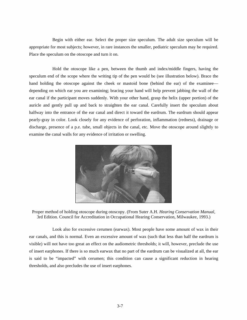
Begin with either ear. Select the proper size speculum. The adult size speculum will be
appropriate for most subjects; however, in rare instances the smaller, pediatric speculum may be required.
Place the speculum on the otoscope and turn it on.
Hold the otoscope like a pen, between the thumb and index/middle fingers, having the
speculum end of the scope where the writing tip of the pen would be (see illustration below). Brace the
hand holding the otoscope against the cheek or mastoid bone (behind the ear) of the examinee—
depending on which ear you are examining; bracing your hand will help prevent jabbing the wall of the
ear canal if the participant moves suddenly. With your other hand, grasp the helix (upper portion) of the
auricle and gently pull up and back to straighten the ear canal. Carefully insert the speculum about
halfway into the entrance of the ear canal and direct it toward the eardrum. The eardrum should appear
pearly-gray in color. Look closely for any evidence of perforation, inflammation (redness), drainage or
discharge, presence of a p.e. tube, small objects in the canal, etc. Move the otoscope around slightly to
examine the canal walls for any evidence of irritation or swelling.
Proper method of holding otoscope during otoscopy. (From Suter A.H. Hearing Conservation Manual, 3rd Edition. Council for Accreditation in Occupational Hearing Conservation, Milwaukee, 1993.)
Look also for excessive cerumen (earwax). Most people have some amount of wax in their
ear canals, and this is normal. Even an excessive amount of wax (such that less than half the eardrum is
visible) will not have too great an effect on the audiometric thresholds; it will, however, preclude the use
of insert earphones. If there is so much earwax that no part of the eardrum can be visualized at all, the ear
is said to be “impacted” with cerumen; this condition can cause a significant reduction in hearing
thresholds, and also precludes the use of insert earphones.
3-7

Make a mental note of the size and direction of the ear canal; this information will be
important when you are conducting the acoustic immittance test.
Remove the otoscope from the ear. On each ear, gently press the helix of the auricle against
the mastoid bone behind the ear using your index and middle fingers in the form of a “V” (see illustration
below), imitating the pressure that will be caused by the headphone when it is placed on the ear. Direct
the light of the otoscope toward the opening of the ear canal and look for any sign of “canal collapse”;
that is, a closing off of the entrance to the ear canal. This problem is more common among the elderly
than in the adolescent population; however, canal collapse can be present in any individual. It is
particularly likely in persons who have small ear canals or whose pinna feels “soft” when you pull on the
outer ear. Collapsed canals can cause elevated thresholds because the test signals cannot enter the ear
canal efficiently. When this condition is noted, the participant should be tested with insert earphones
rather than headphones, provided there are no precluding conditions to the use of inserts. (See
Section 3.5.3.1 for instructions.)
Proper method for checking for collapsed ear canals.
Record the results in the ISIS program as described in Section 3.3.4. Repeat the examination
in the other ear and record the results in ISIS. Remove the speculum from the otoscope and throw it away.
NOTE: Be very careful not to make any mention to the SP of what you observe in otoscopy,
as you are not conducting this check for diagnostic purposes. If the SP inquires about the otoscopic
results, simply say that you are only checking to see which headphones to use.
3-8
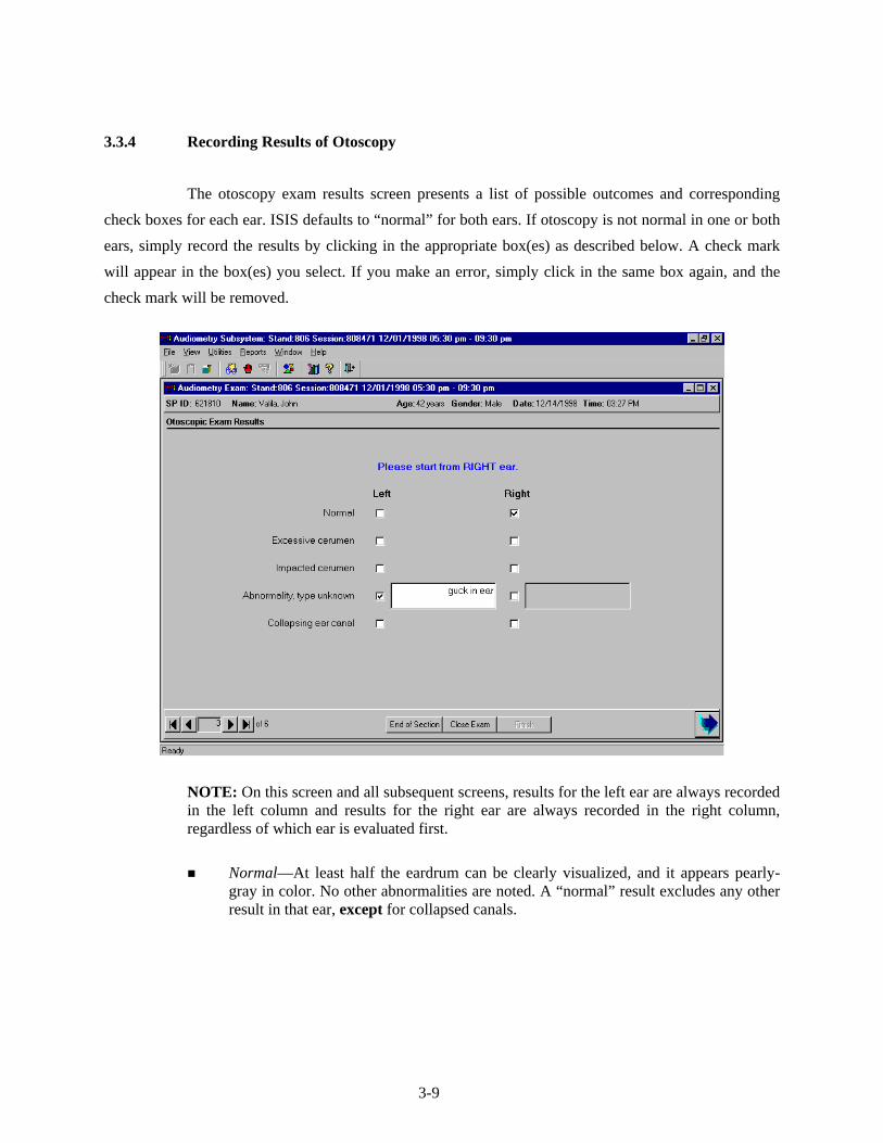
3.3.4 Recording Results of Otoscopy
The otoscopy exam results screen presents a list of possible outcomes and corresponding
check boxes for each ear. ISIS defaults to “normal” for both ears. If otoscopy is not normal in one or both
ears, simply record the results by clicking in the appropriate box(es) as described below. A check mark
will appear in the box(es) you select. If you make an error, simply click in the same box again, and the
check mark will be removed.
NOTE: On this screen and all subsequent screens, results for the left ear are always recorded in the left column and results for the right ear are always recorded in the right column, regardless of which ear is evaluated first.
Normal—At least half the eardrum can be clearly visualized, and it appears pearly-
gray in color. No other abnormalities are noted. A “normal” result excludes any other result in that ear, except for collapsed canals.
3-9

Excessive cerumen—Significant accumulation of earwax in canal, such that view of the eardrum is partially (but not completely) blocked. If less than half the tympanic membrane is visible due to wax, it is considered excessive. This condition precludes the use of insert earphones during audiometry.
Examples of excessive cerumen during otoscopy. (From Sullivan R.F. Audiology Forum: Video Otoscopy.)
Impacted cerumen—Even greater accumulation of earwax in the ear canal, such that
no part of the eardrum can be visualized. This condition precludes the use of insert earphones during audiometry.
NOTE: Excessive cerumen and impacted cerumen cannot both be recorded in the same ear. If you try to mark one after the other has already been marked, the first result will be deleted. If you can see any part of the eardrum, record the result as “excessive cerumen.” If you cannot see any part of the eardrum, record “impacted cerumen” as the finding.
Examples of impacted cerumen during otoscopy. (From Sullivan R.F. Audiology Forum: Video Otoscopy.)
3-10

Other abnormality (Describe)—Any other observation that does not appear normal. This could include drainage (fluid) in the ear canal, blood, a foreign body (e.g., bugs, cotton, a p.e. tube that has ejected itself from the eardrum, etc.), a perforation in the eardrum, a growth in the ear canal, significant skin abnormalities, or anything else that you feel may be cause for concern. Describe the abnormality briefly in the field provided. This finding precludes the use of insert earphones; ISIS will prompt you to send an observation to the MEC physician (see Section 3.6.2).
NOTE: An observation to the physician is not sent automatically. You must re-enter the finding using the standard physician observation procedures within ISIS.
Examples of other findings during otoscopy. Illustration A shows a p.e. tube placed in the eardrum. Illustration B depicts a large perforation in the eardrum; the entire center portion of the membrane is
missing. Illustration C shows a small piece of glass lodged in the ear canal. (From Sullivan R.F. Audiology Forum: Video Otoscopy.)
Potential canal wall collapse—This condition requires the use of insert earphones
during audiometry, provided no other conditions preclude their use.
Example of a collapsed ear canal. (From Sullivan R.F. Audiology Forum: Video Otoscopy.)
3-11
3.4 Acoustic Immittance
3.4.1 Purpose of Acoustic Immittance
Acoustic immittance is a collective term, which refers to measurements of eardrum
compliance. The hearing examination in NHANES includes two acoustic immittance measures:
tympanometry and acoustic reflex testing.
Tympanometry is an objective test of middle ear function. Tympanometry tests the mobility
of the eardrum, from which information regarding the function of the middle ear system can be inferred.
The test is conducted by sealing off the entrance to the ear canal with a rubber cuff, changing the air
pressure within the ear canal, and recording the flexibility of the eardrum in response to the changing
pressure. The eardrum should be most flexible when the air pressure in the ear canal is zero (i.e., equal to
the ambient air pressure). If peak mobility occurs at significant positive or negative pressure, it is an
indication of some disorder in the middle ear. If the eardrum shows little mobility at any pressure, it
indicates that something in the middle ear system—such as fluid from an infection or fixation of the
ossicles—is preventing the eardrum from vibrating properly in response to sound. Tympanometry can
also indicate that the eardrum is too flexible, or that the eardrum is perforated.
Tympanometry is objective in that the examinee is completely passive to the test process.
The equipment is automated, and performs the test and records the results without any need for response
or feedback from the examinee. However, it should be emphasized that tympanometry is an evaluation of
the physiological status of the ear. While tympanometry can point out problems with how the ear is
functioning—which of course may impact hearing sensitivity—it does not directly indicate how well a
person can hear.
The acoustic reflex is an involuntary contraction of the two muscles in the middle ear—the
stapedius and the tensor tympani—in response to loud sounds. When these muscles contract, the ossicles
pull the eardrum slightly back; the middle ear system “stiffens up” and sound is not transmitted as
efficiently. This affords the sensitive inner ear a small bit of protection against potentially damaging
sounds.
3-12

The acoustic reflex is tested by sending a brief tone into the middle ear loud enough to elicit
the reflex, and looking for a resultant change in eardrum mobility as the muscles contract and pull back
on the eardrum. Acoustic reflex test results are useful in clarifying questionable tympanograms, verifying
degree of hearing loss, and distinguishing between sensorineural hearing losses caused by damage to the
cochlea versus the auditory nerve.
3.4.2 Instrumentation for Acoustic Immittance
Both tympanometry and acoustic reflexes are tested using the Earscan impedance
equipment, which was described briefly in Section 2.2.2. The equipment consists of a processor and a
probe. The probe consists of three small tubes: one which sends air pressure into the ear canal, one which
sends a low level tone and presents the louder tones to elicit the acoustic reflex, and one which contains a
microphone to measure the sound reflected back from the eardrum. The probe tip is fitted with rubber
cuffs of various sizes, which are used to seal off the entrance to the ear canal for testing. The processor
interprets the amount of sound reflected back from the eardrum and converts it to a measure of the
stiffness of the eardrum.
3.4.3 Procedure for Acoustic Immittance
After entering results of the otoscopic exam for both ears, advance to the tympanometry
screen by clicking on the forward arrow button.
Explain the immittance test and instruct the examinee in the following manner:
INSTRUCTIONS: “This is a test to measure how well your eardrum is able to move.
It is a completely automatic test, so you will not need to respond in any way. I am going to place a probe snugly against the opening of your ear canal. You will hear a continuous ‘hum’ and feel a little pressure; then you will hear a couple of loud beeps. The test will only take about thirty seconds. It is important that you sit very still, and do not move, speak, or swallow from the time I insert the probe until I tell you the test is finished. Do you have any questions?”
3-13

Perform the test as follows:
Press the SPEC button, then the CLEAR button, to delete any previous test data from the
Earscan. Then press the IMP button to select immittance testing. The screen will read “NO DATA”; and will
display an R or L in the top left corner to indicate the test ear. If necessary, press the LEFT/RIGHT button to
select the proper ear.
Recalling the size and direction of the ear canal, which you noted during otoscopy, select a
probe cuff of proper size to seal off the entrance to the ear canal. Slide the cuff onto the probe, making
sure that the base of the cuff is snug against the probe tip.
NOTE: Most SPs will require the medium-size probe cuff. It is just as difficult to obtain a
good seal with a cuff that is too large as it is with a cuff that is too small. Use the large cuff whenever
necessary; but remember that bigger is not better for everyone!
With one hand, gently pull the auricle up and back to straighten out the ear canal. With the
other hand, firmly press the probe against the entrance to the ear canal (see illustration below). Hold the
probe steady and watch the processor screen. If an airtight seal has been obtained, the screen will read
“STEADY” while it builds the pressure up in the ear canal, then it will read “TESTING.” If an airtight seal
has not been obtained, the screen will read “AIR LEAK”; adjust the position of the probe until the screen
indicates that a seal has been obtained. If the probe is pressed against the wall of the ear canal, the screen
will read “BLOCK” and you will hear a high-pitched tone. Redirect the probe toward the eardrum; you
may need to reexamine the ear canal to assist you in properly directing the probe.
Position of Tympanometer Probe During Immittance Testing
While the test is running, hold the probe as still as possible. Movement of the probe may
cause the Earscan to stop testing or give noisy, inconsistent, or false results. When the Earscan senses the
3-14

probe is near the ear canal, you will hear a low frequency hum. When a seal has been obtained and testing
begins, you will also hear a higher frequency tone. When tympanometry is complete, a graph of the
tympanogram will appear on the screen and the tone will become higher as acoustic reflexes are tested.
Do not remove the probe until the overriding tone stops and the screen reads “REMOVE PROBE.”
NOTE: Try to monitor the progress of the test by listening to the various tones rather than
watching the Earscan screen. It will be easier to hold the probe steady if you keep your eyes on the probe
instead of the screen.
Once the probe has been removed, the screen will again display the graph of the
tympanogram. Look at the graph to determine its adequacy. Tympanograms should be evaluated on the
basis of smoothness and symmetry. A normal tympanogram will have a peak at approximately 0 daPa, or
at the point of the vertical line on the graph. However, the peak may occur in other places if the SP has an
early or resolving infection. In some cases, the tympanogram will be flat, with no peak evident at all.
Such cases include SPs with impacted cerumen, perforated eardrums, or p.e. tubes. However, if the results
are clear and consistent, abnormality is not a reason to reject a tympanogram. Examples of good and poor
tympanograms are shown below.
Clear Normal Clear Flat Noisy; Asymmetrical
If the tympanogram is not clear or if it is flat, it should be rerun once to try to obtain a better
test and/or to verify the flat result. Place the probe against the entrance to the ear canal as before and
Earscan will automatically retest once a seal is obtained. Do not delete the first test; Earscan will
overwrite it. When retesting, be careful to direct the probe properly into the ear canal and to hold the
probe very still during testing; reinstruct the SP if necessary. In order to keep examination time within
limits, the second test will be accepted regardless of its quality.
3-15

After testing is finished on the first ear, press LEFT/RIGHT to select the other ear. The screen
should read “NO DATA” and the letter depicting the test ear should change as appropriate. Repeat the
entire procedure on the second ear.
3.4.4 Recording Results of Acoustic Immittance
After both ears have been tested, transfer the test results from the Earscan to the ISIS
software. Make certain that ISIS is advanced to the “Tympanometer Readings” screen. Press ENTER, then
DATA on the Earscan unit; the screen will read “BUSY” for a few seconds while the data are transferred.
Then click CAPTURE on the ISIS screen to write the data to the database. ISIS will display a message
indicating whether the data were captured successfully or if the data could not be captured, some data are
missing, etc. If data are missing (e.g., results for one ear or acoustic reflexes), retest if possible. (Do not
delete previous results!) Send the data again by pressing ENTER, DATA, and then clicking CAPTURE. If one
or both ears were not able to be tested, click COULD NOT OBTAIN or SP REFUSED, as appropriate.
3-16

When ready to advance to the audiometry screen, ISIS will display a message indicating
which ear to test first and which headphones to use for audiometry. Pay close attention to this message.
Click OK, then click the forward arrow to move on to audiometry.
3.4.5 Troubleshooting Acoustic Immittance
The following are some common problems that may be encountered during tympanometry
testing, and a list of possible solutions that may correct the difficulty.
Display reads AIR LEAK when running test:
- Reset the probe cuff in the ear.
- Pull up and back a little more on the ear to straighten the ear canal.
- Use a different size cuff. (Most SPs should need the middle sized cuff.)
Display reads BLOCK when running test:
- Verify that the probe cuff is in the entrance to the ear canal, not up against another part of the ear.
- Check that the probe tip is not blocked by wax, etc.
- Recall the direction of the ear canal noted on otoscopy and try to direct the probe appropriately.
Display reads NO DATA when running a test, or unit will not run test:
- Make sure you have selected IMP.
- Power the unit off and back on; recalibrate before proceeding.
Earscan takes an abnormally long time to run the immittance test:
- Typically, this means that the seal has been lost.
- Remove the probe and begin again.
ISIS will not capture data:
- Make sure you have pressed ENTER, DATA to send results to ISIS.
- Remember that you must already have advanced to the “Tympanometer Readings” screen when you send the data from the Earscan to ISIS.
3-17

ISIS captures data from only one ear:
- Remember to press LEFT/RIGHT to select the appropriate test ear; otherwise the results from the second ear will overwrite the results from the first ear.
- You must rerun the tests in BOTH ears if results from one ear overwrote results from the other ear, because results from the second ear are now stored as results from the opposite ear.
ISIS indicates that part of the data is missing from one or both ears:
- This generally indicates that you removed the probe before the test had completely finished.
- Rerun the test in the appropriate ear(s).
Results are “noisy”:
- Hold probe very still during test.
- Remind the SP to be as still and quiet as possible (yawning, swallowing, talking, or chewing during the test will result in “noisy” graphs).
If you are ever unsure whether the Earscan is malfunctioning, test it by placing your
finger over the tip of the probe (you should get a BLOCK error message) or by running a calibration. If the
Earscan can calibrate or gives the BLOCK message, it is not malfunctioning; reseat the probe, try a
different size probe cuff, etc.
3.5 Audiometry
3.5.1 Purpose of Audiometry
Audiometry is the measurement of hearing sensitivity. The NHANES hearing component
includes pure tone air conduction audiometry, which tests the hearing sensitivity of the entire auditory
system by presenting pure tone signals to the ear through earphones and varying the intensity of the
signals until the level is identified at which the person is just able to hear the sound. This level is known
as the person’s threshold; clinically, threshold is usually defined as the level at which the subject will be
able to detect the signal 50 percent of the times that it is presented. Pure tones are presented at frequencies
across the range of human hearing. Because the tones are presented at the external ear, and processing of
those signals through the auditory nervous system is necessary in order for the subject to be aware and
3-18

respond that the signal was heard, this type of testing evaluates the auditory system as a whole, and is
capable of identifying hearing problems at almost any level within the auditory system.
3.5.2 Instrumentation for Audiometry
Pure tone air conduction threshold testing is done using the Interacoustics Model AD226
audiometer. The audiometer is an electronic device capable of generating pure tone signals, which can be
adjusted in both frequency and level. The Interacoustics AD226 is a microprocessor audiometer, which
means it has been programmed to conduct the threshold test automatically. It is capable of presenting the
tones, recording the subject’s responses, adjusting the level of the tone accordingly, and determining
when the threshold has been found. The AD226 can also be used as a manual audiometer, which means
the frequencies and the tester, who also makes the threshold determination, adjusts levels.
The AD226 is supplied with standard audiometric headphones, EARtone 3A insert
earphones, a patient response switch, and an external power supply.
3.5.3 Procedure for Audiometry
3.5.3.1 Preliminary Procedures and Instructions
The examinee will remain in the sound room for pure tone audiometry. The ear to be tested
first will be varied in order to prevent biasing the data. The fifth digit of the sample person identification
number (SPID) will be used to identify which ear should be tested first; if the fifth digit is 5-9, the right
ear will be tested first, and if the fifth digit is 0-4, the left ear will be tested first. For example, SP#
448937 will have his left ear tested first, and SP# 879592 will have her right ear tested first. However, if a
subject indicated that he or she has better hearing in one ear than the other, the ear with the better
sensitivity should be tested first. The ISIS program will prompt which ear is to be tested first as you move
from the tympanometry screen to the audiometry screen.
Be certain that the SP has removed eyeglasses, earrings, chewing gum, hair ornaments, hats,
wigs, or anything else that might interfere with proper placement of the headphones. Hair should be
pushed away from the entrance to the ear canal. Also, verify that any hearing aids have been removed. If
3-19

the examinee must wear his or her hearing aid in order to hear the test instructions, remember to have the
examinee remove it before testing begins.
Explain the test and instruct the examinee in the following manner:
INSTRUCTIONS: “This last test measures how well you can hear certain sounds. I
am going to place these earphones on your head and you will hear a series of short beeping sounds through them. They will have various pitches, both low and high, and will gradually become softer and softer until you can’t hear them anymore. Each time you think you hear the tones, no matter how quiet they seem, push down on this button. You will have to listen very carefully. The beeping sounds will come in groups of three or four – beep beep beep. You only have to push the button once for each set. Also, you do not have to wait until you have heard all three; you should press the button as soon as you think you hear them. We will be starting in your right/left ear. Do you have any questions?”
Place the appropriate headphones on the SP. The RED earphone goes on the RIGHT ear
and the BLUE earphone goes on the LEFT ear. Proper placement of the headphones is essential to
obtaining accurate hearing thresholds. Do not permit the examinee to place the headphones on herself or
himself.
Standard headphones:
Standard headphones will be the default, unless the potential for collapsing canals was noted on the otoscopic exam.
To place these headphones on the SP, fully extend the height of the headset. Position the earphones such that the diaphragm of the earphone is aimed directly at the opening of the ear canal, pushing aside any hair from over the ear. When the earphones have been positioned, hold them in place and slide the top of the headset down so that it rests solidly on the top of the examinee’s head (This step may disarrange the examinee’s hairstyle but it is important for proper use of the headphones.) Make sure that the earphones exert firm pressure on each ear and form a good seal.
Insert Earphones:
Insert earphones will be used when the potential for collapsing canals was noted on otoscopy, and for any retests when there is a significant difference in threshold between the right and left ears at the same frequency. Insert earphones may not be used when excessive or impacted cerumen was noted in either ear, or when there was another abnormality noted in either ear at otoscopy.
Particular care must be taken in proper insertion, as improper insertion will result in inaccurate threshold levels. Drape the Velcro strip behind the SP’s neck to support the earphones. Slowly roll (do not squeeze) the foam tip into as small a diameter as
3-20

possible; there should be no creases or wrinkles in the compressed foam. Pull up and back on the helix (upper part) of the outer ear to straighten the ear canal, and quickly insert the foam tip to a point such that the outer edge of the tip is flush with the entrance to the ear canal. Hold the foam plug in place with a fingertip until the foam has completely expanded (approximately 10 seconds). Correct insertion is illustrated in the first figure below. Incorrect (i.e., shallow) insertion is illustrated in the second figure. If the foam tip is not inserted properly, remove it and try again.
After placing the headphones on the SP, make sure the examinee is seated in such a way that
you can observe him or her during the test protocol, but the examinee cannot observe what you are doing
or how the equipment is being operated. Generally, it is best to have the examinee facing the back wall of
the room. Explain to the examinee that you are asking him or her to face this way to prevent distraction.
Close both the door to the sound room and the exterior door to the audiometry exam room
prior to the start of testing. Assure the examinee that, although the door must be closed during testing, you
will be observing the test through the window and he or she should signal if anything is needed.
3.5.3.2 Automated Audiometry Procedures
Automated audiometry is the procedure in which the frequency, stimulus level, presentation
of test signals, and determination of threshold are controlled by a computer program built into the
audiometer. The AD226 audiometer contains such software, and is capable of conducting the hearing test
in much the same way as you would conduct the test manually (as described in the next section).
3-21

Automated audiometry will be the standard test procedure in NHANES, except under certain conditions
(see Section 3.5.3.3).
Once the preliminary procedures have been completed and the SP is ready to begin the test,
verify that the audiometer is set as follows:
MAN REV button set to MAN;
PULSE button set to ___;
1 5 dB button set to 5;
RIGHT or LEFT ear selected (whichever ISIS indicated should be tested first); and
Appropriate HEADSET selected
The appropriate headset must be selected on both the audiometer and the headphone selector box.
On the audiometer, the standard headphones are the default setting; if the audiometer is set for standard headphones, the display will read “Ph.” in the lower left corner. To set the audiometer for insert earphones, press SHIFT/RIGHT or SHIFT/LEFT (depending on which ear is to be tested first; pressing SHIFT/RIGHT also selects the right ear as the test ear and pressing SHIFT/LEFT selects the left ear). This is very important, as it changes the internal calibration levels to those necessary for inserts. When the audiometer is set for insert earphones, the display will read “Ins.” in the lower left corner. To switch back to standards, press SHIFT/RIGHT or SHIFT/LEFT again.
Set the appropriate headset on the headphone selector box by turning the knob toward “Standards” or “Inserts.”
When starting a test on a new SP, always begin by deleting any thresholds, which may
be stored in the audiometer; press and hold SHIFT/1 5 dB until the display reads “All thresholds are del.”
Press AUTO THRESHOLD to begin testing. Monitor the test as it is conducted. The green TONE
light will flash when a test signal is being presented to the examinee; the red RESPONSE light will flash
when the examinee presses the response switch to indicate that he or she heard the tone. As you are
monitoring the test, watch for the following:
SP attention.
Periodically observe the SP to verify that everything is well and that he or she is not watching the audiometer for cues to the presentation of test signals. If you need to
3-22

communicate with the SP, you can do so by pressing the TALK FORWARD button. If the SP needs to communicate with you, you must pause the test (by pressing AUTO
THRESHOLD) and go into the sound booth.
Frequent false positive responses.
A false positive occurs when the subject responds to a signal that was not presented. False positives are indicated by a flash of the red RESPONSE light that does not immediately follow a flash of the green TONE light. In other words, the examinee indicated that he or she heard the tone, but the tone was not presented. If more than three false positives are noted at a given test frequency, press AUTO THRESHOLD to pause the test and reinstruct the participant (see Section 3.5.8 on Difficult Test Situations). Press AUTO THRESHOLD again to resume testing (the AD226 will pick up at the frequency at which the test was paused). If false positives persist, the subject should be tested manually.
Long searches for threshold at a given frequency.
A long search for threshold can occur when the subject has difficulty distinguishing the test signal from tinnitus, when the subject becomes fatigued, etc. If the examinee spends an inordinate amount of time at a given frequency, you may want to pause the test (by pressing AUTO THRESHOLD) and reinstruct the examinee. If the situation does not improve, the test should be completed manually (see Section 3.5.8 on Difficult Test Situations). Skip the problem frequency temporarily and try it again at a later point in the test. It is not possible to skip frequencies or test frequencies in a different order during an automated test.
Slow response time or inability to operate the response switch.
If the examinee has limited dexterity, he or she may be unable to operate the response switch or may not be able to respond in the time window programmed into the audiometer for a valid response. In such cases, the examinee will have to be tested manually using a different response mechanism—such as raising his or her hand or nodding his or her head (see Section 3.5.3.3 on Manual Audiometry and Section 3.5.8 on Difficult Test Situations).
Test/retest consistency at 1000 Hz.
The automated procedure programmed into the AD226 tests 1000 Hz twice in each ear as a measure of the reliability of the subject’s responses. It is important to note both 1000 Hz thresholds in a given ear and make sure that there is no more than 10 dB difference between them. If the test/retest thresholds differ by more than 10 dB in the same ear, the audiometer will beep and display the message “Retest failed! Press Auto Threshold.” Press AUTO THRESHOLD to stop the test and reinstruct the participant—emphasizing that he or she only press the response switch when fairly certain that the test tone is heard (remind him or her that the tones will be pulsed).
To restart the test, press RIGHT or LEFT to select the ear that was under test (the audiometer will have automatically reset itself for the right ear when you pressed
3-23

AUTO THRESHOLD). Press SHIFT/1 5 dB until the display reads “PH-R Thresholds are del.” (instead of PH-R, you may also see PH-L, IN-R, or IN-L, depending on which ear was being tested and which headphones were being used for the test). Make sure you have selected the correct test ear before deleting! Do not continue to press SHIFT/1 5 dB or you will delete thresholds in both ears. Press AUTO THRESHOLD to continue the test.
If the test/retest at 1000 Hz fails a second time in the same ear, the test should be ended.
Excessive ambient room noise.
Observe the Quest bioacoustic simulator from time to time throughout the test to verify that the power light is still flashing and that the ambient room noise is within acceptable limits. If the power light is not flashing, change the battery in the simulator after you finish the examination. If the noise monitor lights remain on for more than a few seconds, press AUTO THRESHOLD to pause the test until the noise goes away; when ambient levels have quieted sufficiently, press AUTO THRESHOLD again to resume testing.
When all frequencies have been tested, the audiometer will beep and the display will read
“Successfully ended. Press Auto Threshold.” Press AUTO THRESHOLD to stop the test.
3.5.3.3 Manual Audiometry Procedures
Manual audiometry is the procedure in which the technologist controls the frequency,
stimulus level, and presentation of test signals and makes the determination as to when threshold has been
identified. It is essential that hearing tests given manually follow the same protocol as hearing tests done
automatically by the audiometer in order to obtain comparable results. Therefore, it is very important that
the procedures outlined in this section be followed exactly.
Manual audiometry is done in lieu of automated audiometry when any of the following
circumstances exists:
The examinee lacks the dexterity necessary to operate the response switch;
The examinee appears confused by or unable to “keep up with” the automated test (i.e., he or she responds to the signal slowly, and therefore the response is not counted by the audiometer, which looks for a response within a specific time window following the stimulus);
3-24

More than three false positive responses are noted at any given test frequency during the automated procedure; and
A threshold exceeds 100 dB (90 dB at 8000 Hz).
In situations in which the automated test has already determined threshold at some test
frequencies when a circumstance arises that dictates the need for manual testing, the technologist should
pick up the manual procedure where the automated procedure left off. It is not necessary to go back and
begin the audiometry all over. However, as soon as manual testing has begun, the remainder of the test
should be done manually. At the end of the test, note on the audiometry results screen in which ear and at
which frequency the manual procedure was begun.
First, verify that the audiometer is set up properly. If you are beginning a test on a new SP,
PRESS SHIFT/1 5 dB until the display reads “All thresholds are del.” If you are continuing a test that was
begun in automated mode, do not delete, or the thresholds already stored in the audiometer will be lost!
Set the audiometer controls as follows:
MAN REV button set to MAN;
PULSE button set to ___;
1 5 dB button set to 5;
RIGHT or LEFT ear selected (whichever ISIS indicated should be tested first); and
Appropriate HEADSET selected (as described in Section 3.5.3.2).
Set the frequency to 1000 Hz and the intensity level (using the left HL dB dial) to 30 dB.
Present the tone by pressing the TONE SWITCH for about 1 second (about 3 pulses). If the
examinee does not respond, increase the intensity in 15 dB steps until a response is obtained. You will be
able to increase the level to 100 dB HL. If no response is obtained by 75 dB HL and the examinee did
not indicate a lot of trouble hearing, stop the test and listen to the output of the earphone yourself to verify
that the equipment is working properly.
When a positive response is obtained from the examinee, drop the level in 10 dB steps and
present the signal again until no response is obtained.
3-25

When there is no response, increase the intensity in 5 dB steps and present the signal each
time until the tone can again be heard by the examinee. Count this response toward threshold.
Continue to search for threshold in this manner—decreasing the stimulus in 10 dB steps
following each positive response and increasing the stimulus in 5 dB steps following each nonresponse.
Count responses made following an increase in stimulus intensity toward threshold (these
are called “ascending presentations”); do not count responses made following a decrease in stimulus
intensity toward threshold (these are called “descending presentations”).
Threshold is defined as the lowest intensity at which the tone has been heard by the
examinee at least 50 percent of the time following a minimum of three ascending presentations at that
level (e.g., at least 2 out of 3, 2 out of 4, 3 out of 5, etc.).
To summarize the procedure, once you have obtained an initial response from the
SP, use the UP 5, DOWN 10 method to search for threshold. Count responses while you are going UP toward threshold. Stop when the SP has responded to half the presentations at a given level (obtain at least two responses).
Record the threshold manually in the AD226 by pressing STORE. Press the frequency DECR
button twice to change the test frequency to 500 Hz. Reset the intensity to 30 dB HL (or 15 dB above the
threshold level at 1000 Hz, whichever is higher). Repeat the threshold search procedure and press STORE
to record the threshold.
The audiometer will automatically advance again to 1000 Hz. Find the threshold again. If the
new threshold is within 10 dB of the original threshold at 1000 Hz, press SHIFT/BONE (the display should
read “UCL” under the test frequency), then press STORE. Press SHIFT/BONE again to exit the UCL mode
(Verify that the display no longer shows “UCL.”) and continue testing in the normal manner. (The
audiometer will automatically advance to the next test frequency.) You must store the second 1000 Hz
threshold in UCL mode or the audiometer will overwrite the first 1000 Hz threshold.
If the new thresholds differ from the original threshold by more than 10 dB, stop the test and
reinstruct the examinee. (See Section 3.5.8 on difficult testing situations.) The audiometer does not check
the test/retest variability automatically when testing in manual mode, so you will have to remember the
initial 1000 Hz threshold and evaluate this yourself. The ISIS system will alert you at the end of the test if
3-26

you fail to note the inconsistency between test and retest thresholds at 1000 Hz. However, it will not do so
until the test has been completed and the thresholds have been captured. At this point, there will not be
time to go back and retest. Therefore, it is very important that you monitor the test/retest variability
as the test is underway.
Continue to test the remaining frequencies: 3000, 4000, 6000, and 8000 Hz. Always begin
with an initial intensity of 30 dB HL or intensity level 15 dB above the threshold at the preceding
frequency, whichever is greater.
When thresholds have been obtained at all frequencies in the first test ear, press the RIGHT or
LEFT button to shift to the other ear. Conduct the test in this ear in exactly the same way, including the
threshold recheck at 1000 Hz.
If the SP does not respond to the test signal at the default intensity limit of the audiometer
(100 dB HL at 500-6000 Hz; 90 dB HL at 8000 Hz), it is possible to increase the intensity 20 dB further
by using the Extended Range mode. Before testing in an extended range, listen through the
headphones to rule out an equipment malfunction. To activate the extended range, press EXT RANGE; a
“+” will appear to the left of the intensity level on the display (you must have the intensity set to at least
80 dB HL to enter the extended range mode). Continue searching for threshold in the same manner. (If the
attenuator drops below 80 dB HL [70 dB at 8000 Hz], the audiometer will automatically exit the extended
range mode, and you will have to reactivate by pressing EXT RANGE again.) If there is still no response
from the SP, store “No Response” as the threshold by pressing SHIFT/STORE. No response thresholds are
indicated by “NRS” on the AD226 display and when displayed by ISIS.
Exit the extended range mode by dropping the intensity level below 80 dB HL (70 dB at
8000 Hz) or by pressing EXT RANGE again.
3-27
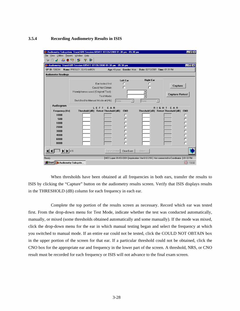
3.5.4 Recording Audiometry Results in ISIS
When thresholds have been obtained at all frequencies in both ears, transfer the results to
ISIS by clicking the “Capture” button on the audiometry results screen. Verify that ISIS displays results
in the THRESHOLD (dB) column for each frequency in each ear.
Complete the top portion of the results screen as necessary. Record which ear was tested
first. From the drop-down menu for Test Mode, indicate whether the test was conducted automatically,
manually, or mixed (some thresholds obtained automatically and some manually). If the mode was mixed,
click the drop-down menu for the ear in which manual testing began and select the frequency at which
you switched to manual mode. If an entire ear could not be tested, click the COULD NOT OBTAIN box
in the upper portion of the screen for that ear. If a particular threshold could not be obtained, click the
CNO box for the appropriate ear and frequency in the lower part of the screen. A threshold, NRS, or CNO
result must be recorded for each frequency or ISIS will not advance to the final exam screen.
3-28

If one or more frequencies were accidentally skipped, ISIS will permit you to go back and
test those frequencies. When you have obtained the missing thresholds, click the “Capture” button again
to transfer the thresholds to the results screen.
3.5.5 Retesting with Insert Earphones
3.5.5.1 Crossover Principles
There are times during audiometric testing that the signal being presented to the test ear is
loud enough that it can actually be heard by the other ear (i.e., the nontest ear). When this occurs, it is
difficult to determine if the threshold obtained is truly the threshold of the test ear, or an artifact of the
nontest ear (which is the ear with better hearing).
How does the test signal get to the nontest ear? In basic audiometric testing, this generally
occurs when the signal in the headphone is so intense that its vibration causes the bones of the skull to
vibrate as well. Because the cochleas are enclosed within the skull, they can be stimulated by the
vibratory motion of the head.
There is a law of physics, which states that when a vibratory source is applied to a solid
mass, the vibrations set up within the mass have the same intensity throughout the object, regardless of
where on the object the vibratory source is applied. For example, imagine that a vibrating tuning fork is
placed on one end of a table. If you were to place your ear against the table at the end opposite the tuning
fork, the sound you would hear would be just as loud as if you were to place your ear against the table at
the end nearest the tuning fork. There is essentially no loss of vibratory energy across the table, and
therefore no attenuation (loss) of the audible signal.
Because the human skull is essentially one solid bone, both cochleas are stimulated equally
by any vibration of the bone. Therefore, if the signal being presented to the test ear is sufficiently intense
to set the skull in motion, it has the potential to stimulate the cochlea of the opposite ear.
The stimulus intensity required to set the skull in motion varies across individuals and across
the range of test frequencies. However, it is not possible to know in advance how loud the stimulus must
be for crossover to occur in a particular individual; and it would be very difficult to remember a different
3-29

intensity level for each audiometric test frequency. Therefore, in order to make things simple, clinicians
choose a conservative value that represents the minimum level that might cause the skull to vibrate and
the test signal to “cross over” and be heard in the nontest ear—regardless of individual differences or test
frequency. The value generally chosen is 25 dB for low frequencies and 40 dB for mid-to-high
frequencies when testing with standard headphones.
Whenever the threshold at any given frequency is poorer in one ear than the other by
25 dB (at 500 and 1000 Hz) or 40 dB (at 2000-8000 Hz) or more (i.e., whenever there is a 25 or 40 dB
difference between ears at a given frequency), the nontest ear could be responding to the test signal.
The threshold in the test ear is therefore questionable.
Because insert earphones are smaller, and less mass is in direct contact with the head, a
louder stimulus is required before there is the potential for crossover to occur. The value generally agreed
upon as the minimum level, which might cause the skull to vibrate when testing with insert earphones is
60 dB, regardless of frequency. Therefore, whenever there is the potential for crossover using standard
headphones, those frequencies will be retested using insert earphones.
3.5.5.2 Procedure for Retesting with Insert Earphones
Retesting with insert earphones will be accomplished in NHANES whenever testing with
standard headphones results in a difference in threshold between the right and left ears at the same
frequency of 25 dB or more at 500 or 1000 Hz, or 40 dB or more at 2000 Hz up (provided, of course, that
inserts are not contraindicated for that SP based on otoscopy findings). After pure tone test results are
captured, the ISIS system will prompt you if retesting is necessary. The boxes in the RETEST
THRESHOLD (dB) column will be highlighted to indicate which ear must be retested, and at which
frequency(s).
Remove the standard headphones from the examinee and instruct the examinee that he or she
will now be listening to some tones through a different headset, but should continue to respond as before.
Insert the earphone tips as explained in Section 3.5.3.1.
Delete the original test thresholds from the audiometer by pressing SHIFT/1 5 dB until
the display reads “All thresholds are del.” Press SHIFT/RIGHT or SHIFT/LEFT (depending on which ear is
3-30

to be retested) on the AD226 to switch to insert earphone testing. (The display will read “Ins.” in the
lower left corner.) Turn the knob on the headphone selector box to “Inserts.”
If all frequencies must be retested, conduct the test in the automated mode as usual. If only
certain frequencies must be retested, conduct the test manually using the FREQUENCY INCR and DECR
buttons to select the appropriate frequencies and pressing STORE to record the new thresholds in the
audiometer. It is not possible to test only certain frequencies in the automated mode. When retesting with
inserts, it is not necessary to obtain a second 1000 Hz threshold unless you are retesting the entire ear in
automated mode.
3.5.6 Recording Retest Results in ISIS
When all required frequencies have been retested, click the CAPTURE RETEST button on the
ISIS audiometry screen to transfer the retest thresholds to ISIS. If any frequencies that required retest
were omitted, ISIS will prompt you to go back and obtain those thresholds. (Click CAPTURE RETEST again
to transfer the missing thresholds to ISIS.) If a particular threshold could not be obtained, click the CNO
box for the appropriate ear and frequency. ISIS will not advance to the final screen if results are missing
at any frequency.
3.5.7 Considerations to Ensure Threshold Accuracy
Accurate pure tone testing sounds very simple, but a number of precautions are necessary in
order to ensure that threshold measurements are accurate:
Vary the interval between stimulus presentations; stimuli, which are presented too
consistently, may permit the examinee to develop a response rhythm, which can lead to false positive responses.
Keep stimulus presentations to approximately one second (or about three pulses). Longer presentations may result in false positives.
Do not pulse the tones manually. Always use the audiometer’s multiple-pulse function and press the TONE SWITCH until three or four pulses have been presented by the audiometer.
3-31

Avoid giving visual cues that might indicate stimulus presentations (e.g., looking at the subject each time a tone is presented; using excessive arm movement in the operation of the audiometer).
Avoid excessive activity, which may distract the examinee.
If responses to tones at the same frequency show large inconsistencies (i.e., more than 10 dB), reinstruct the examinee and begin that frequency again.
If difficulty is encountered in determining threshold at a particular frequency, continue with other test frequencies and return to the problem frequency later. Spending too much time on one frequency will tire and/or frustrate the examinee and exacerbate the problem.
Make periodic checks for false positives by not presenting the tone for 8-10 seconds and verifying that the subject does not respond.
Count only ascending presentations when determining threshold.
Avoid being influenced by the initial threshold at 1000 Hz when performing the recheck.
Always double-check the audiometer settings and dial readings.
In addition, keep in mind that pure tone audiometry is a subjective test, which means that it
relies on the perception of the subject. Therefore, the accuracy of the results can be affected by a number
of subject variables, including motivation, attention, familiarity with the task, etc. Your rapport with the
SP can be an important factor in encouraging him or her to complete the test well.
3.5.8 Difficult Test Situations
Obtaining accurate pure tone thresholds can be a challenge under some circumstances.
Listed below are some of the most common difficulties encountered in audiometric testing and
suggestions for overcoming them.
Significant pre-existing hearing loss
Some SPs with significant hearing loss will actually be quite experienced with audiometric testing procedures, and may not present much of a challenge at all. But others will not be familiar with the threshold testing procedure and may have difficulty hearing the test instructions. If the SP wears a hearing aid, have him or her put it back on between each test while the explanations and directions are being given. Face the person when you speak, and talk a little more slowly than usual (but don’t
3-32

exaggerate your facial expressions). Use motions to help augment your message. If the SP has sufficient vision and reading skills, have him or her read the test instructions from the card kept in the sound room.
False Positives/Inconsistent Responses
Responses, which continuously vary over a range of more than 10 dB, are too inconsistent to accurately determine threshold. In such cases, the best course of action is to reinstruct the examinee, indicating that he or she should only respond when fairly certain that a tone is heard. Remind the SP that the signals will be a series of three or four pulses; instructing the SP to wait until he or she has heard at least two of the pulses may also help resolve the problem.
If the false positives/inconsistent responses are only at one frequency, try skipping that frequency and coming back to it later. Sometimes the SP just needs a break from listening to the same signal.
Tinnitus
Tinnitus (the presence of ringing or other sounds in the ear) can make it difficult for the SP to distinguish the test tones from the other noises he or she hears. The pulsed tone specified by the protocol should alleviate this problem somewhat. It may be necessary to skip the frequency corresponding to the SP’s tinnitus.
Fatigue
Listening for signals near threshold level is a difficult and demanding task. An SP may weary of it quickly; if the SP arrives fatigued, he or she may have difficulty staying on task. Verbal reinforcement may help keep the SP alert; you can speak to the SP through the headphones by holding down the TALK FORWARD button (the AD226 defaults to a talk forward intensity of 60 dB—which is a comfortable conversational intensity for most normal-hearing people; if the SP has a hearing loss, adjust the talk forward volume using the HL DB knob).
Poor coordination/long tone-response latency
Some examinees may be slow to respond when they hear the test tones, due to poor dexterity or other reasons. Reinstructing the SP to respond as soon as he or she hears the signal may help the situation. Otherwise, try to get a feel for the “rhythm” of the SP’s response pattern so that you will better know when a response is valid and when it is random. If another method of responding is more workable (e.g., raising a hand or finger, nodding the head, etc.), use it.
Comprehension or language difficulties
If an SP has difficulty understanding the test instructions, try another mode of communication. Use motions to demonstrate the test directions while you explain them. If the SP has sufficient vision and reading skills, have him or her read the test instructions from the card kept in the sound room. If a family member or friend
3-33

accompanied the SP to the MEC and is available, ask him or her to help you explain the procedures to the SP. If you do not think the SP understands the directions enough to provide valid test results, skip the pure tone testing and note “Communication Problem” as the reason for the incomplete test.
Anxiety
Some SPs may be anxious about the test, for various reasons. Perhaps the most common is claustrophobia. Try to put the SP at ease as much as possible. In some cases, it may be possible to conduct the test with the door to the sound room partly or completely open…but only if the octave monitor on the Quest BA-201-25 indicates that the noise levels in the sound room are still sufficiently quiet. If the ambient noise in the room is too high with the sound booth door open, and the SP is unable to complete the test with the door closed, skip pure tone testing and record “Physical Limitation” as the reason for the incomplete test.
Reinstructing the SP can sometimes help to alleviate a difficult test situation or improve the
accuracy and efficiency of the threshold test. Reinstruction is helpful in situations that involve a
misunderstanding of test instructions. For example:
SP pushes the button for each beep in the series;
SP waits for all beeps to play before responding; and
SP fails test/retest at 1000 Hz once.
However, reinstructing the SP does not help when the situation involves an inability to
follow test instructions. For example:
SP repeatedly fails test/retest at 1000 Hz;
SP continues to respond with more than 3 false positives per frequency; and
SP’s dexterity is too poor to press the response button in a timely manner.
When reinstructing the SP, be certain to tailor the reinstruction to the specific
circumstance. Repeating the same directions initially given to the SP does not help. If the SP did not
understand the first time, a verbatim recitation of the same instructions is not likely to be successful the
second time. If the SP fails the test/retest at 1000 Hz or if the SP has more than 3 false positives at one
frequency, emphasize that he or she should only respond when sure that tones have been heard. If
the SP responds outside the time window of the audiometer, emphasize that he or she should respond
as soon as tones are heard.
3-34

Finally, if for any reason you feel that the SP is unable to provide reliable thresholds, end the
test. No data is preferable to poor data; and there is no mechanism for indicating reliability. Thresholds
recorded in ISIS will be assumed to be valid; therefore, if you feel they are not, discontinue testing and
enter the reason for the partial exam on the status screen (see Section 3.6.1).
3.5.9 Troubleshooting Audiometry
The following are some problems that may be encountered in operating the audiometer or
conducting pure tone threshold testing, and a list of possible solutions that may be used for
troubleshooting.
Audiometer does not turn on:
- Make sure both power switches (audiometer and power supply) are turned on; and
- Verify that cable from power supply to outlet is inserted securely (This connection is very touchy!)
Headphones are out of calibration on daily check:
- Check battery in bioacoustic simulator;
- Correct headphones selected on audiometer;
- Pulsing is off (both lights off on PULSE button); and
- For standards, make sure insert earphone adaptors were removed from simulator.
No tones in headphone:
- Proper headphone selected on headphone box;
- All headphones plugged into appropriate booth jacks; and
- Correct ear selected.
“Hissing” sound in headphones:
- Turn off masking signal. (Press SHIFT and turn right DB HL knob counterclockwise.)
3-35

Cannot activate extended range:
- Make sure intensity is set to at least 80 dB; and
- Extended range can only be activated in manual mode (does not work if AUTO
THRESHOLD is activated).
Patient response light does not come on or stays on and does not turn off:
- Check that response switch is plugged all the way into booth jack (not the cable from the bioacoustic simulator);
- Make sure SP is pressing button all the way down.
LEDs on control buttons do not light:
- Adjust LED ADJ knob.
Push buttons do not respond:
- Wait one second and try again. (Buttons do not work when the microprocessor is busy.)
Intensity changes in 1 or 2 dB steps:
- Press 1 5 DB button several times to reset to 5 dB. (Press AUTO THRESHOLD to pause test if necessary.)
Cannot delete stored thresholds:
- Thresholds cannot be deleted if they are displayed; press SHIFT + EXT RANGE to turn off display, then delete.
3.6 Post-Examination Procedures
3.6.1 Closing the Hearing Exam in ISIS
Click the forward arrow to advance to the audiometry component status screen. If any part of
the examination was incomplete (or if the exam was not done at all), ISIS will prompt you to enter an
3-36

explanation code. The codes are standardized across all exam components. Refer to the guidelines below
in assigning codes for incomplete hearing examinations:
Safety Exclusion – Refers to an exclusion based on precluding conditions as outlined
in the protocol. As there are no precluding conditions for the hearing component, there should seldom, if ever, be cause to select this code;
SP Refusal – Refers to circumstances in which all or part of the exam was omitted because the SP refused, was uncooperative, etc.; but was physically able to undertake the component;
No Time – Indicates that the session ended and the exam could not be conducted or had to be terminated before it was completed;
Physical Limitation – Refers to the physical inability of the SP to complete all or part of the exam; for example, the SP could not remove his or her hearing aids unassisted, could not respond consistently to the test tones, was claustrophobic and could not sit in the sound booth; had no external ear canals, etc;
Communication Problem – Indicates that the exam could not be accomplished because of a language barrier, cognitive deficit, or other communication impairment;
Equipment Failure – Problem with test equipment or the ISIS system, or high ambient noise, which precluded pure tone testing;
SP Ill/Emergency – SP had to leave abruptly due to a serious, unforeseen circumstance;
Interrupted; and
Other (Specify) – For use when the reason cannot be coded with any of the other categories. A brief explanation (40 characters or less) in the accompanying comment field is required. Use of this category should be limited as much as possible.
Click the “Finish” button to exit the component.
3.6.2 Referral
If a finding warranting an observation to the physician was recorded during otoscopy, and
the observation was not sent, ISIS will prompt you once more to make the observation before closing the
exam.
3-37

3-38
3.6.3 Directions to Examinee
When the entire test has been completed and the SP has been closed out of the component,
return any items that the examinee may have removed at the beginning of the exam (e.g., hearing aids,
eyeglasses, earrings, hair ornaments, etc.). Wait a few moments for a message from the coordinator
indicating to which station the SP should be directed next. Thank the examinee and direct him or her to
the next station. If the examinee inquires about the results of any of the hearing examination procedures,
explain to him or her that you simply conduct the tests and that the results will be given to him or her with
some explanatory materials at the end of the exam.
NEVER, NEVER, NEVER interpret the results of the hearing exam for the SP or give
any indication of the test results!
3.6.4 Final Procedures
If time permits following the exam, reset the test room for the next SP. Discard the otoscope
speculum, headphone covers, and foam ear tips if you have not already done so. (Be very careful not to
throw away the white plastic connectors between the foam tips and earphone tubing.) Remove the
probe cuff from the immittance probe and place it in the wash container. Delete the results stored in the
Earscan by pressing SPEC, then CLEAR. Delete the results from the audiometer by pressing SHIFT/1 5 dB
until the display reads “All thresholds are del.”

4. QUALITY CONTROL
4.1 Quality Control Procedures
To ensure complete and accurate data collection and to document the data collection process,
a variety of quality control procedures have been developed for this survey. Insofar as possible, checks
have been programmed into the ISIS software to notify you when data are incomplete or inconsistent. It is
important, however, that you also pay close attention to the completeness and accuracy of the data
recorded in ISIS, particularly that:
The correct response is marked for each item;
No conflicting responses have been marked for the same item;
Data from previous SPs are deleted from the Earscan and audiometer before beginning a test on a new SP; and
Thresholds, No Response, or CNO are entered for each test frequency.
It is particularly important that you pay close attention to calibration checks of the
equipment. Follow all calibration procedures exactly and record them in ISIS appropriately. When
keeping hard-copy logs, verify that:
All values are recorded in the proper spaces on the proper logs; and that no required
information is missing (e.g., equipment serial numbers, dates, technician ID, etc.);
All entries are legible; and
Values fall within the specified calibration limits.
When conducting additional calibration checks mid-stand (e.g., checking audiometer output
with the sound level meter when the daily bioacoustic check is out of range), be certain to record results
and send them to the consulting audiologist at the end of the stand. It is particularly important to
maintain hard-copy records of sound level meter checks made when the daily audiometer check is out-
of-range. Currently, the hard-copy record is the only evidence that the audiometer was still in
calibration when the bioacoustic check indicates a problem.
4-1

4-2
4.2 Review of Data
Audiometry data will be reviewed periodically by a consulting audiologist to verify that all
necessary data are being collected and saved, to evaluate the consistency of results across the tests
conducted on an individual SP (i.e., otoscopy, immittance, and audiometry), and to monitor for any
difficulties with test procedures. If problems are noted, the audiologist will contact the MEC team to
discuss the problem and make appropriate recommendations.
Monitoring the quality of data collection will also be carried out by Westat component staff,
who will generate reports from the ISIS Intraweb at the end of every stand. The number of audiometry
examinations and examination times, cumulative and by technician, as well as reasons for not done and
partial examinations, will be analyzed for each stand.
4.3 Field Observations
Approximately three times a year, a consulting audiologist will visit each MEC team and
observe 15 to 20 examinations given by the health technologists. This visit will serve to verify that the
audiometry protocol is still being implemented properly and consistently. Problems or variations in the
standard procedures will be reviewed with the technologists at the end of each day. If serious issues are
encountered, retraining may be scheduled.
Additionally, NCHS staff and Westat component staff will visit the MECs periodically to
observe the audiometry examinations. A checklist will be used to verify that standard testing procedures
are being strictly followed, including test instructions, placement of the headphones and tympanometry
probe, position of the examinee during the test, manual audiometry, etc. These observations will serve to
further monitor the quality of data collection and to provide constructive feedback to the MEC staff.

Appendix A
Inventory of Audiometric Equipment and Supplies

Audiometry
Consumable
Site ID:
Part # Description Par Unit Count
EXAM SUPPLIES 58-104 Alcohol Wipes 1 box
SO-EPG Ear Phone Guards, Paper 1 box RAS-420-
2006 EarLink 3A Tips (Foam, Small) 50 each
RAS-420-2005
EarLink 3A Tips (Foam, Standard) 50 each
RAS-420-2028
EarLink 3A Tips (Foam, X-Large) 24 each
52432 Otoscope Specula (Kleenspec - 2.5 mm) 1 sleeve 52434 Otoscope Specula (Kleenspec - 4 mm) 3 sleeve SO-PC Pipecleaners 1 bag
OFFICE SUPPLIES
DUR PC1604
Batteries, 9-Volt - do not count what is in equip. 15 each
SPARE PARTS & TOOLS
03100 Otoscope Bulbs (Halogen 12v/20watt) - do not count bulbs in equip.
2 each
* Expired Lot
A-1

A-2
Audiometry
Non-Consumable
Site ID:
Part # Description Par Unit Count
EXAM SUPPLIES ER3-04 Eartip Connectors (white) - do not count tips on equip. 10 each
XTIP25A Eartips (Rubber, Adult) 25 each XTIP25C Eartips (Rubber, Child) 25 each
XTIP10INF Eartips (Rubber, Infant) 10 each SO-HB Headband for Standard Headphones 2 each SO-PJ Petroleum Jelly 1 each Vivitar
VPT-120 Tripod - Lightweight Photo/Video 1 each
SPARE PARTS & TOOLS
41005 Hex Key Set, Standard, Buck Bros. 7 pc. 1 each 72300 Otoscope Battery, Rechargeable 3.5 volt 2 each
QB-4LC Quick Release Platform 1 each 62-102 Screwdriver, Phillips Head, Stanley #2 1 each 62-104 Screwdriver, Straight Head, Stanley #4 1 each
5165533014 Wrench, Husky Combination 7/16 1 each EMERGENCY SUPPLIES
CPR Mask - Adult 1 each