Embed Size (px)
Citation preview
Audio @ Video @ Data Communications
17.06.2013 short descriptions GFPE 2010 e.ppt 1
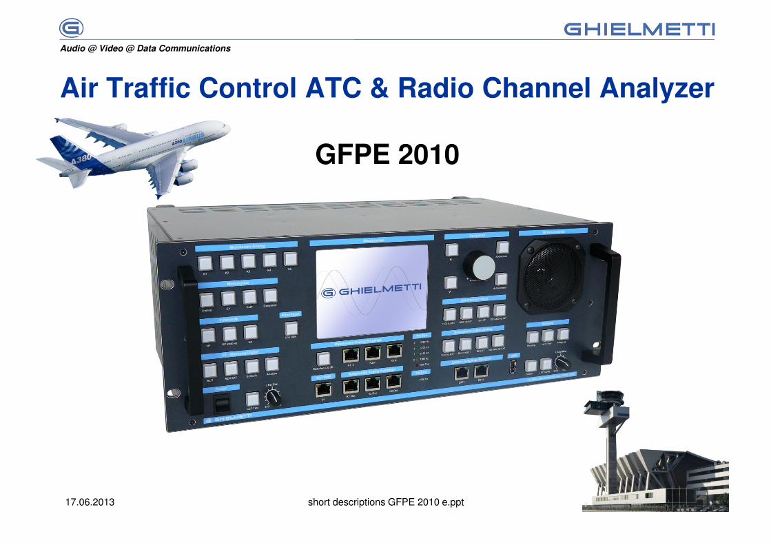
Air Traffic Control ATC & Radio Channel Analyzer
GFPE 2010
Audio @ Video @ Data Communications
17.06.2013 short descriptions GFPE 2010 e.ppt 2
Basics
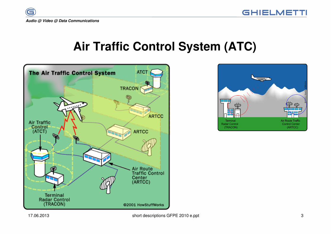
The communication between the air-traffic controller in the control tower and the pilot on board of his aircraft is operated by voice radio. This voice communication mainly transmits information on flight situation, position of the aircraft, altitude, air speed, or such like.
The most important monitoring unit besides the radar is the aircraft radio. Therefore the idea of safety is a cornerstone for the whole air-traffic control system with highest requirements regarding reliability and availability.
Air Traffic Control & Radio Channel Analyzer GFPE 2010 has been designed and developed to test and maintain existing and new communication networks for air trafic control ATC. FO, radio-relay analog and digital (E1) voice communication channels, AoIP, VoIP.
Audio @ Video @ Data Communications
17.06.2013 short descriptions GFPE 2010 e.ppt 3
Air Traffic Control System (ATC)
Audio @ Video @ Data Communications
17.06.2013 short descriptions GFPE 2010 e.ppt 4
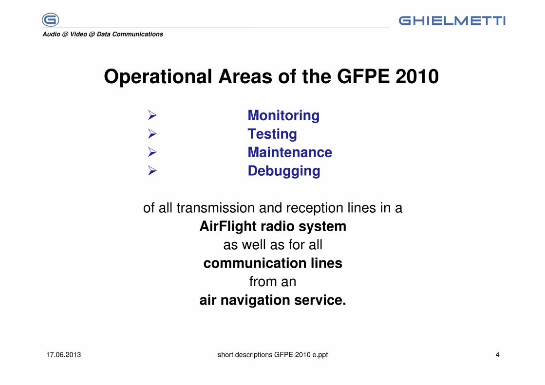
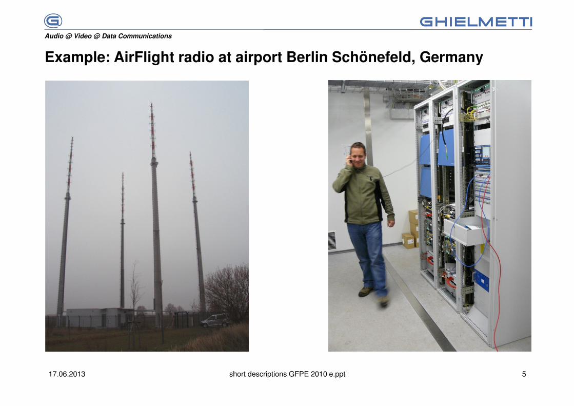
Operational Areas of the GFPE 2010
� Monitoring
� Testing
� Maintenance
� Debugging
of all transmission and reception lines in a AirFlight radio system
as well as for all communication lines
from an air navigation service.
Audio @ Video @ Data Communications
17.06.2013 short descriptions GFPE 2010 e.ppt 5
Example: AirFlight radio at airport Berlin Schönefeld, Germany
Audio @ Video @ Data Communications
17.06.2013 short descriptions GFPE 2010 e.ppt 6
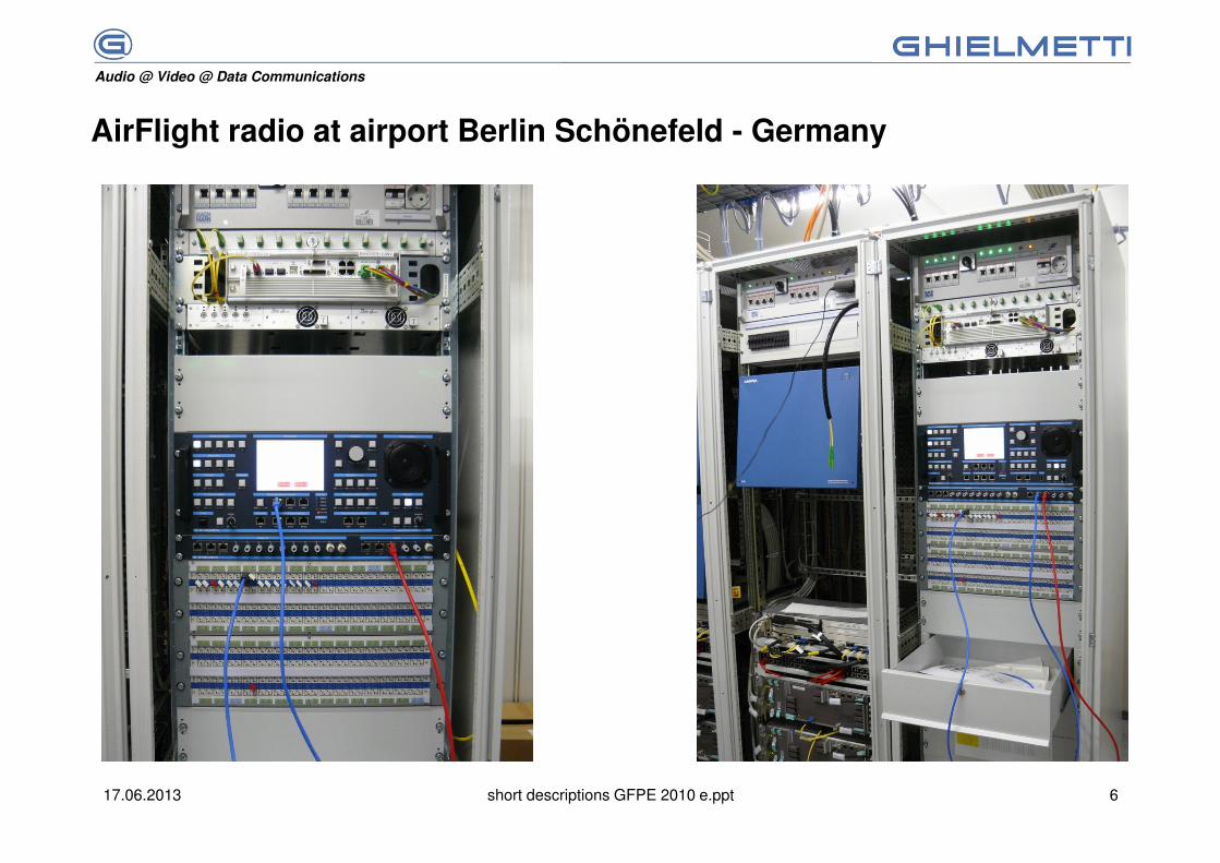
AirFlight radio at airport Berlin Schönefeld - Germany
Audio @ Video @ Data Communications
17.06.2013 short descriptions GFPE 2010 e.ppt 7
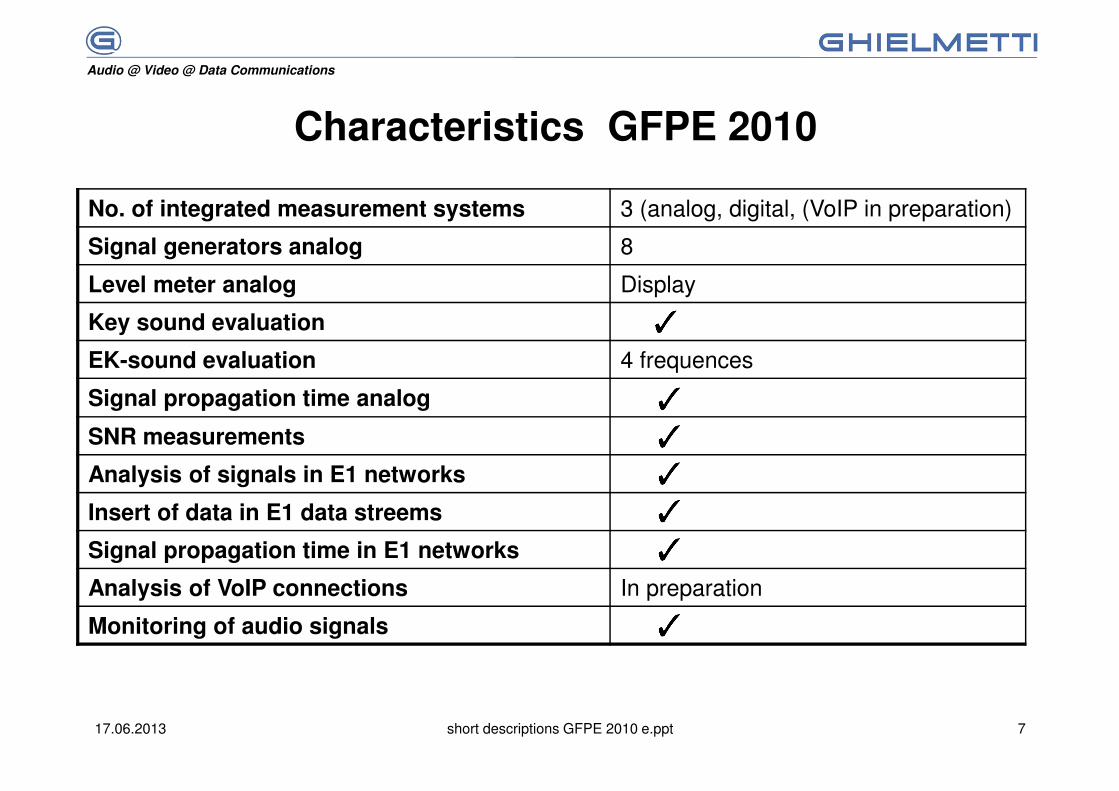
Characteristics GFPE 2010
No. of integrated measurement systems 3 (analog, digital, (VoIP in preparation)
Signal generators analog 8
Level meter analog Display
Key sound evaluation
EK-sound evaluation 4 frequences
Signal propagation time analog
SNR measurements
Analysis of signals in E1 networks
Insert of data in E1 data streems
Signal propagation time in E1 networks
Analysis of VoIP connections In preparation
Monitoring of audio signals
Audio @ Video @ Data Communications
17.06.2013 short descriptions GFPE 2010 e.ppt 817.06.2013 8
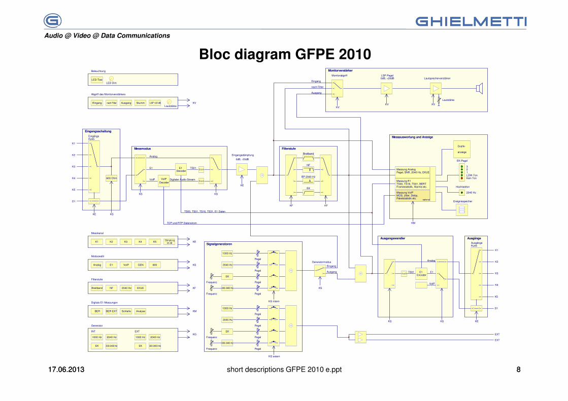
Bloc diagram GFPE 2010
NF 2040 Hz EKUEBreitband
LED-Test
Filterstufe
Beleuchtung
nach Filter
Abgriff des Monitorverstärkers
LED Dim
LSP +20 dBEingang Ausgang StummLautstärke
KF
KV
K2
Messkanal
K5K1 K3 K4 KE
E1
Moduswahl
600 Analog VoIP GEN KS
Generator
2040 Hz1000 HzKG
Digitale E1-Messungen
BER EXTBER KM
2040 Hz
EK
300-3400 Hz
Schleife Analyse
Pegel
Frequenz
EXT 1
EXT 2
K1
K2
K3
K4
K5
600 Ohm
KS KS
E1
VoIP
Analog
KSKE
TS01
TS00, TS01, TS16, TS31, E1 Daten
KF KF
Breitband
NF
BP 2040 Hz
EK
Messung AnalogPegel, SNR, 2040 Hz, EKUE
321LÜW-TonKein Ton
2040 Hz
EK-Pegel
Hochtastton
anzeige
Messung E1TS00, TS16, TS31, BERTFramestatistik, Alarme etc.
KV
Lautstärke
Ereignisspeicher
KS KS
K5
K4
K3
K2
K1
AusgängeRJ45
EingängeRJ45
KVKV
LSP-Pegel0dB, +20dB Lautsprecherverstärker
Eingang
nach Filter
Ausgang
Eingangsdämpfung
Pegel
Pegel
Pegel
D zu A
KM
KS
EK 300-3400 Hz
Generatormodus
Eingang
Ausgang
Monitorabgriff
Monitorverstärker
Filterstufe
Ausgangswandler
Signalgeneratoren
Eingangsschaltung
E1Decoder
VoIPDecoder
Messung VoIPMOS, Jitter, Delay,Paketstatistik etc.
Grafik-
Messauswertung und Anzeige
TCP und RTP Datenstrom
Digitaler Audio Stream
E1
VoIP
Analog
TS01A zu D
E1Encoder
Messmodus
1000 Hz
Frequenz
INT EXT
2040 Hz1000 Hz
EK 300-3400 Hz
KG intern
2040 Hz
EK
300-3400 Hz
Pegel
Frequenz
Pegel
Pegel
Pegel
1000 Hz
Frequenz
KG extern
optional
Dämpfung20 dB
KE
0dB, -20dB
D1
KE
D1
D zu A
Ausgänge
Audio @ Video @ Data Communications
17.06.2013 short descriptions GFPE 2010 e.ppt 9
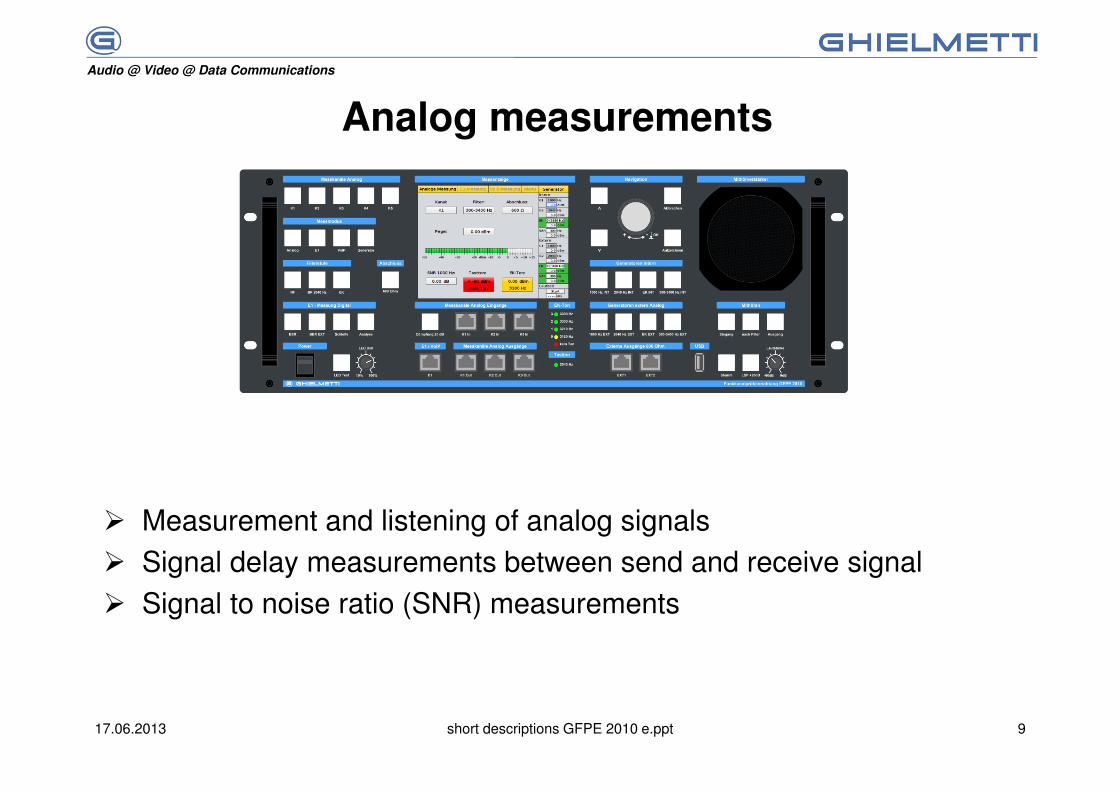
Analog measurements
� Measurement and listening of analog signals
� Signal delay measurements between send and receive signal
� Signal to noise ratio (SNR) measurements

Audio @ Video @ Data Communications
17.06.2013 short descriptions GFPE 2010 e.ppt 10
GFPE
Verbindung der GFPE mit einem Empfängerausgang
RX
Measurement and listening of analog signals
Measuring of audio signals with EK-sound-signals on a receiver output
Summing signal 1000 Hz and 3300 Hz
Display of signal level and EK-signal.Connection to receiver output
Audio @ Video @ Data Communications
17.06.2013 short descriptions GFPE 2010 e.ppt 11
TXGFPE
Verbindung der GFPE mit einem Sendereingang
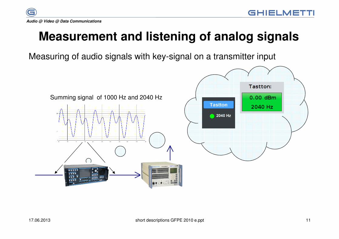
Measurement and listening of analog signals
Measuring of audio signals with key-signal on a transmitter input
Summing signal of 1000 Hz and 2040 Hz
Audio @ Video @ Data Communications
17.06.2013 short descriptions GFPE 2010 e.ppt 12
Signal to noise ratio measurement (SNR)
� Tapping of 1000 Hz signal at connector "EXT1" or "EXT2«with a interconnection to a line or a load.
� Reconnecting to an analog input.
Measurement result:
� Continuous signal to noise ratio measurement

Audio @ Video @ Data Communications
17.06.2013 short descriptions GFPE 2010 e.ppt 13
Measuring of signal propagation time in analog and digital networks
GFPE
analog analog
Loop-back connection
GFPE MUX
analog
MUX
analog2MBit/s 2MBit/s
Loop-back connection
Audio @ Video @ Data Communications
17.06.2013 short descriptions GFPE 2010 e.ppt 14
E1- Measurement
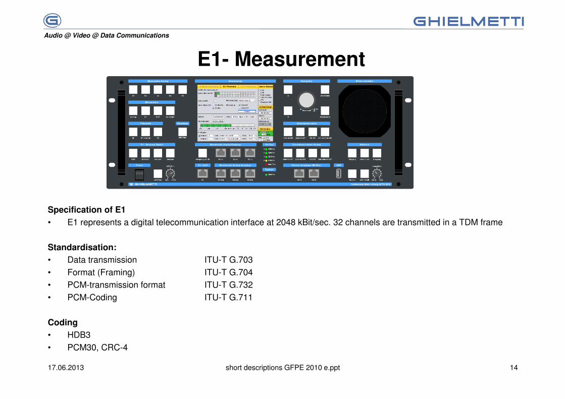
Specification of E1
• E1 represents a digital telecommunication interface at 2048 kBit/sec. 32 channels are transmitted in a TDM frame
Standardisation:
• Data transmission ITU-T G.703
• Format (Framing) ITU-T G.704
• PCM-transmission format ITU-T G.732
• PCM-Coding ITU-T G.711
Coding
• HDB3
• PCM30, CRC-4

Audio @ Video @ Data Communications
17.06.2013 short descriptions GFPE 2010 e.ppt 15
E1 - Measurements(ITU-T G.703 and G.704)
� Detection and measuring of framed E1 signals
� Splitting of a framed E1 signal in the different time slots
� Generating of a framed E1 signal
� alteration or suppression of time slots
� Loop test of E1 channels
� BER test, internal and external of framed E1 signals
� Evaluation of alarms and error bits of framed E1 signals
� Paste of error bits in time slots and frame bits.
� Statistics to no. of frames , bit errors and alarms.

Audio @ Video @ Data Communications
17.06.2013 short descriptions GFPE 2010 e.ppt 16
Measurement mode E1-loop-back
There are several options for loop-back measurements
• 4-wire connection between transmit and receive channel
• 2-wire connection, only receive channel
empfangen
FPE
Gerät 1 senden
Abtasten der Empfangsverbindung einer bestehenden 2 Mb/s-Leitung
Gerät 2
empfangen
FPE
Gerät 1 senden
Abtasten der Sendeverbindung einer bestehenden 2 Mb/s-Leitung
Gerät 2
Sendepfad ausgeschaltet Sendepfad ausgeschaltet
empfangen
FPETx
oder sendenRx
Punkt-Punkt-Verbindung mit einem Sender oder EmpfängerPoint to point connection between transmitter and receiver
Detection of a transmit signal in an active 2 Mb/s connection Detection of a transmit signal in an active 2 Mb/s connection
Transmit is switched ofTransmit is switched of
receive
transmit
receive receive
transmit transmitUnit 1 Unit 2 Unit 1 Unit 2

Audio @ Video @ Data Communications
17.06.2013 short descriptions GFPE 2010 e.ppt 17
Measuring mode "Analyse"
The GFPE 2010 is interconnected in an existing E1- connection.
empfangen
FPE
Gerät 1 senden
Einschlaufen in eine bestehende 2 Mb/s-Leitung
Gerät 2
empfangen
FPE
Gerät 1 senden
Einschlaufen in eine bestehende 2 Mb/s-Leitung
Gerät 2Unit 2 Unit 2Unit 1Unit 1 transmit transmit
receive receive
Loop into an existing 2 Mb/s-line Loop into an existing 2 Mb/s-line
Audio @ Video @ Data Communications
17.06.2013 short descriptions GFPE 2010 e.ppt 18
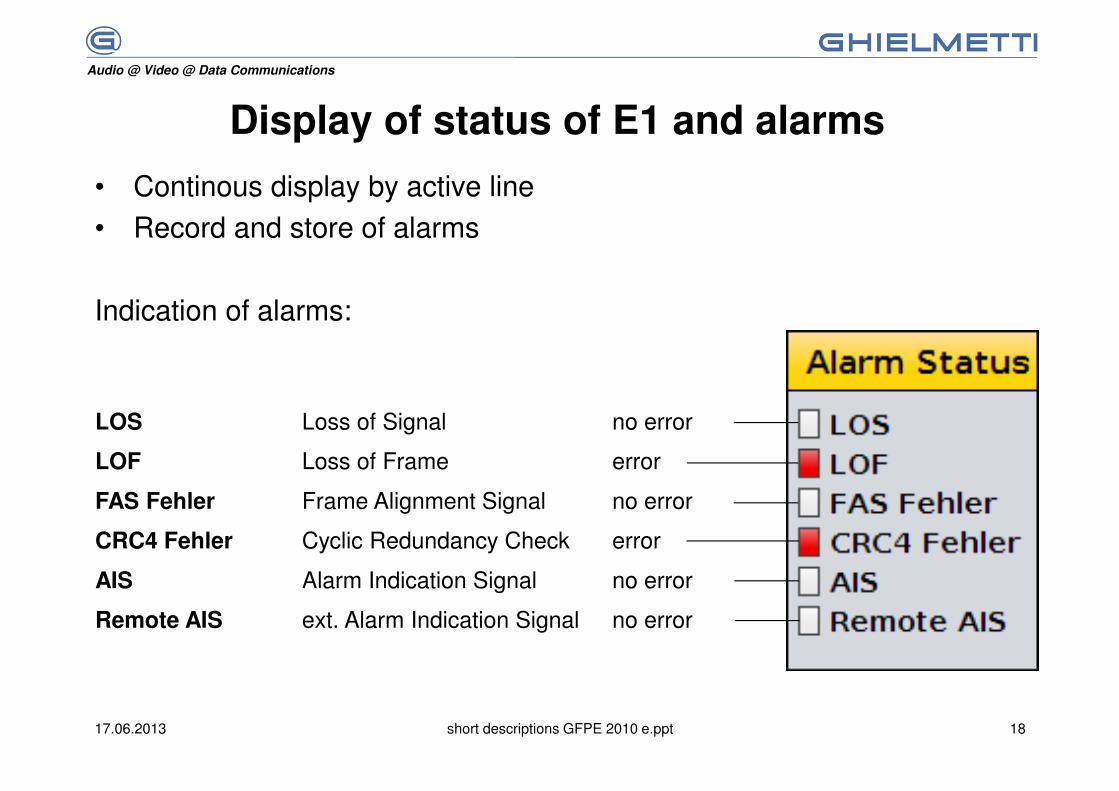
Display of status of E1 and alarms
• Continous display by active line
• Record and store of alarms
Indication of alarms:
LOS Loss of Signal no error
LOF Loss of Frame error
FAS Fehler Frame Alignment Signal no error
CRC4 Fehler Cyclic Redundancy Check error
AIS Alarm Indication Signal no error
Remote AIS ext. Alarm Indication Signal no error
Audio @ Video @ Data Communications
17.06.2013 short descriptions GFPE 2010 e.ppt 19
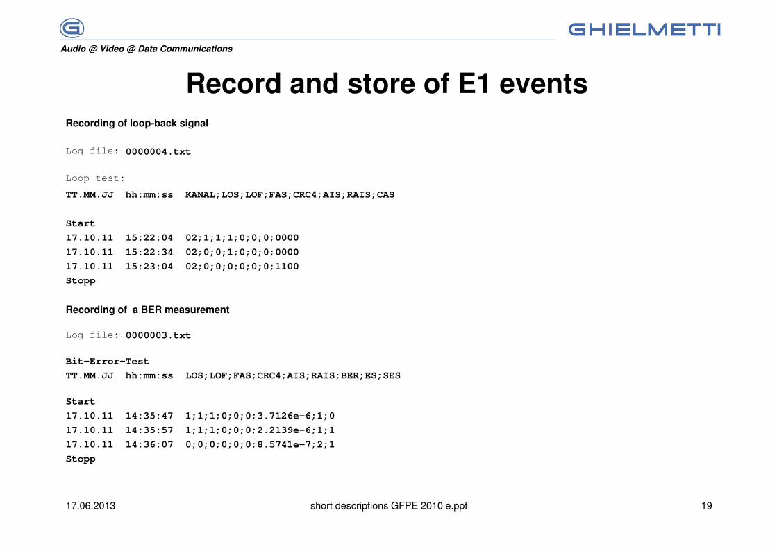
Record and store of E1 eventsRecording of loop-back signal
Logdatei: 0000004.txt
Schleifenmessung
TT.MM.JJ hh:mm:ss KANAL;LOS;LOF;FAS;CRC4;AIS;RAIS;CAS
Start
17.10.11 15:22:04 02;1;1;1;0;0;0;0000
17.10.11 15:22:34 02;0;0;1;0;0;0;0000
17.10.11 15:23:04 02;0;0;0;0;0;0;1100
Stopp
Recording of a BER measurement
Logdatei: 0000003.txt
Bit-Error-Test
TT.MM.JJ hh:mm:ss LOS;LOF;FAS;CRC4;AIS;RAIS;BER;ES;SES
Start
17.10.11 14:35:47 1;1;1;0;0;0;3.7126e-6;1;0
17.10.11 14:35:57 1;1;1;0;0;0;2.2139e-6;1;1
17.10.11 14:36:07 0;0;0;0;0;0;8.5741e-7;2;1
Stopp
Log file:
Loop test:
Log file:
Audio @ Video @ Data Communications
17.06.2013 short descriptions GFPE 2010 e.ppt 20
The unit satisfies the requirements of following standard and recommendations:
EUROCAE
ETSI
ITU-T G.703
CCIR
ETSI
EN 301 489-22
CE
VDE
DIN
Audio @ Video @ Data Communications
17.06.2013 short descriptions GFPE 2010 e.ppt 21
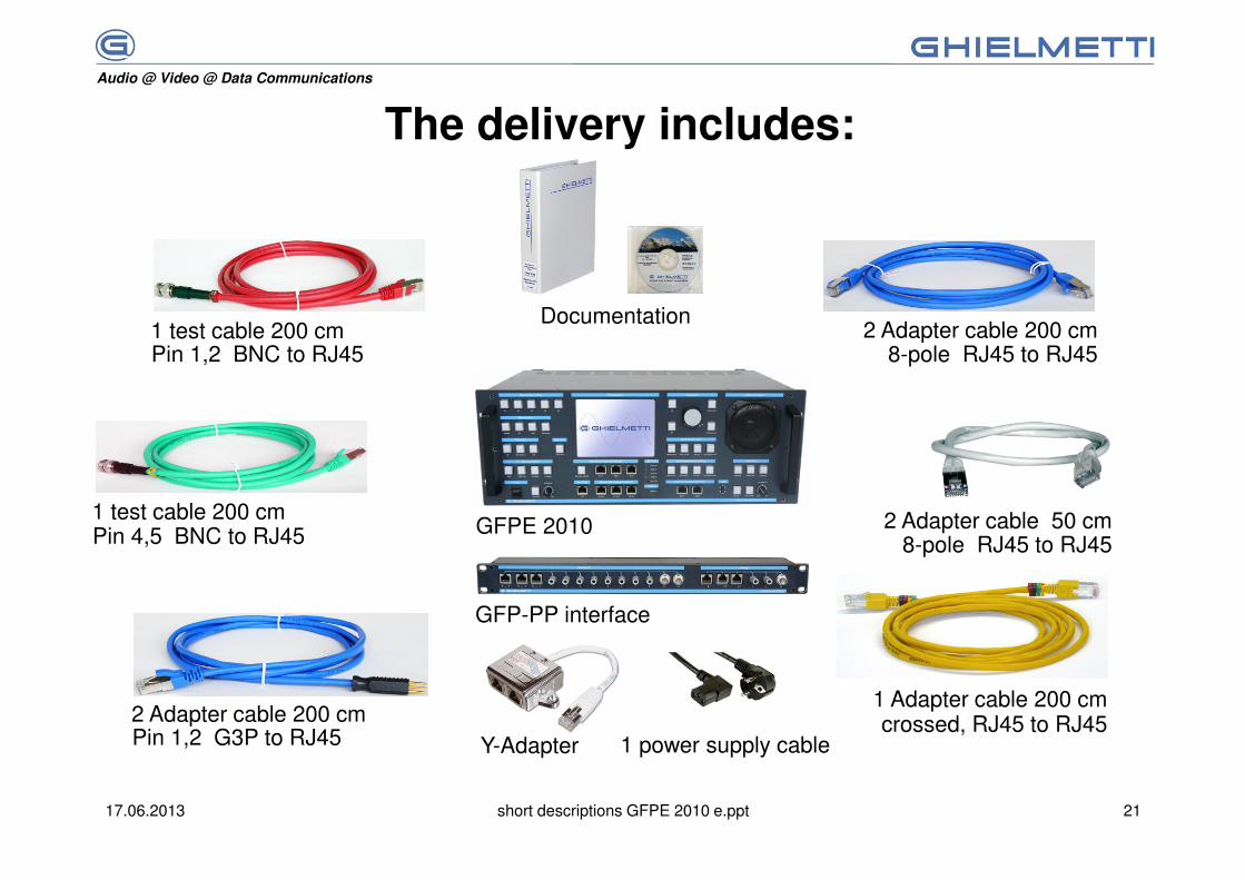
The delivery includes:
GFPE 2010
GFP-PP interface
1 test cable 200 cm
2 Adapter cable 50 cm8-pole RJ45 to RJ45
1 power supply cable
Documentation
1 Adapter cable 200 cm
2 Adapter cable 200 cm8-pole RJ45 to RJ45Pin 1,2 BNC to RJ45
1 test cable 200 cmPin 4,5 BNC to RJ45
2 Adapter cable 200 cmPin 1,2 G3P to RJ45
crossed, RJ45 to RJ45Y-Adapter

Audio @ Video @ Data Communications
17.06.2013 short descriptions GFPE 2010 e.ppt 22