Embed Size (px)
Citation preview
Application Note
R11AN0186EU0101 Rev.1.01 Page 1 of 20 Jan 8, 2018
Renesas Synergy™ Platform
Audio Playback DAC Framework Module Guide Introduction This module guide will enable you to effectively use a module in your own design. Upon completion of this guide, you will be able to add this module to your own design, configure it correctly for the target application, and write code using the included application project code as a reference and efficient starting point. References to more detailed API descriptions and suggestions of other application projects that illustrate more advanced uses of the module are available on the Renesas Synergy Knowledge Base (as described in the References section at the end of this document) and should be valuable resources for creating more complex designs.
The Audio Playback Framework handles synchronization to play mono 16-bit pulse-code modulation (PCM) samples. For hardware access it uses the digital-to-analog converter (DAC) Audio Playback Framework or I2S Audio Playback Framework hardware port. This module guide focuses on the DAC Audio Playback Framework hardware port. The DAC Audio Playback Framework module is a high-level API for audio playback applications and is implemented on sf_audio_playback_hw_dac. The module handles the synchronization needed to play 16-bit pulse-code modulation (PCM) samples. The Audio Playback Framework uses the DAC, the Asynchronous General Purpose Timer (AGT) or General Purpose Timer (GPT), and the DMA or DTC data-transfer peripherals on a Synergy MCU. A user-defined callback can be created to respond additional data needs.
Contents
1. Audio Playback Hardware DAC Framework Module Features ................................................. 2
2. Audio Playback Framework Module APIs Overview ................................................................ 2
3. Audio Playback Hardware DAC Framework Module Operational Overview ............................. 3 3.1 Audio Playback Hardware DAC Framework Module Important Operational Notes and Limitations ...... 5 3.1.1 Audio Playback Hardware DAC Framework Module Operational Notes .............................................. 5 3.1.2 Audio Playback Hardware DAC Framework Module Limitations .......................................................... 6
4. Including the Audio Playback Hardware DAC Framework Module in an Application ................ 6
5. Configuring the Audio Playback Hardware DAC Framework Module ....................................... 7 5.1 Configuration Settings for the Audio Playback Framework Low-Level Modules .................................... 8 5.2 Audio Playback Hardware DAC Framework Module Clock Configuration ............................................ 13 5.3 Audio Playback Hardware DAC Framework Module Pin Configuration ................................................ 13
6. Using the Audio Playback Hardware DAC Framework Module in an Application ................... 14
7. The Audio Playback Hardware DAC Framework Module Application Project ......................... 15
8. Customizing the Audio Playback Hardware DAC Framework Module for a Target Application .................................................................................................................. 18
9. Running the Audio Playback Hardware DAC Framework Module Application Project ............ 18
10. Audio Playback Hardware DAC Framework Module Conclusion ........................................... 18
11. Audio Playback Hardware DAC Framework Module Next Steps ............................................ 19
12. Audio Playback Hardware DAC Framework Module Reference Information .......................... 19
R11AN0186EU0101 Rev.1.01
Jan 8, 2018

Renesas Synergy™ Platform Audio Playback DAC Framework Module Guide
R11AN0186EU0101 Rev.1.01 Page 2 of 20 Jan 8, 2018
1. Audio Playback Hardware DAC Framework Module Features The Audio Playback Hardware DAC Framework module supports the following features:
• Plays long buffers by splitting the data into manageable chunks. • Repeats playback until a ThreadX® timeout (for repeated audio like sine wave tones or looped background music). • Requests next data using callback after last buffer playback begins. • Software volume control. • Pauses and resumes functions. • Scaling to move signed 16-bit PCM data into range of the unsigned 12-bit DAC. • Basic mixing for multiple streams.
Figure 1 Audio Playback Hardware DAC Framework Module
2. Audio Playback Framework Module APIs Overview The Audio Playback Framework defines APIs for such operations as opening, starting, playing and stopping. A complete list of the available APIs, an example API call and a short description of each can be found in the following table. A table of status return values follows the API summary table.
Table 1 Audio Playback Framework Module API Summary Function Name Example API Call and Description
.open g_sf_audio_playback0.p_api->open( g_sf_audio_playback0.p_ctrl, g_sf_audio_playback0.p_cfg);
Configure the audio framework by creating a thread for audio playback and configuring HAL layer drivers used.
.start g_sf_audio_playback0.p_api->start( g_sf_audio_playback0.p_ctrl, &p_data, 100);
Play audio
.stop g_sf_audio_playback0.p_api->stop( g_sf_audio_playback0.p_ctrl);
Stop audio playback.
.pause g_sf_audio_playback0.p_api->pause( g_sf_audio_playback0.p_ctrl);
Pause audio playback.
Renesas Synergy™ Platform Audio Playback DAC Framework Module Guide
R11AN0186EU0101 Rev.1.01 Page 3 of 20 Jan 8, 2018
Function Name Example API Call and Description
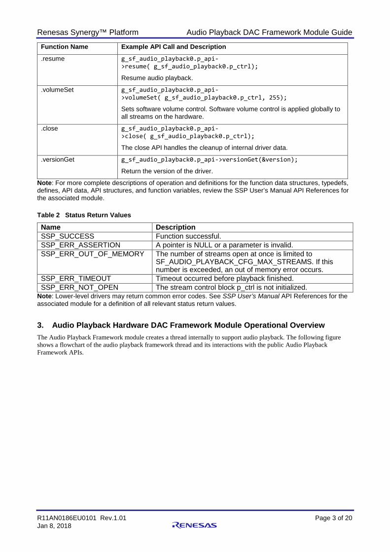
.resume g_sf_audio_playback0.p_api->resume( g_sf_audio_playback0.p_ctrl);
Resume audio playback.
.volumeSet g_sf_audio_playback0.p_api->volumeSet( g_sf_audio_playback0.p_ctrl, 255);
Sets software volume control. Software volume control is applied globally to all streams on the hardware.
.close g_sf_audio_playback0.p_api->close( g_sf_audio_playback0.p_ctrl);
The close API handles the cleanup of internal driver data.
.versionGet g_sf_audio_playback0.p_api->versionGet(&version);
Return the version of the driver.
Note: For more complete descriptions of operation and definitions for the function data structures, typedefs, defines, API data, API structures, and function variables, review the SSP User’s Manual API References for the associated module. Table 2 Status Return Values
Name Description SSP_SUCCESS Function successful. SSP_ERR_ASSERTION A pointer is NULL or a parameter is invalid. SSP_ERR_OUT_OF_MEMORY The number of streams open at once is limited to
SF_AUDIO_PLAYBACK_CFG_MAX_STREAMS. If this number is exceeded, an out of memory error occurs.
SSP_ERR_TIMEOUT Timeout occurred before playback finished. SSP_ERR_NOT_OPEN The stream control block p_ctrl is not initialized.
Note: Lower-level drivers may return common error codes. See SSP User’s Manual API References for the associated module for a definition of all relevant status return values.
3. Audio Playback Hardware DAC Framework Module Operational Overview The Audio Playback Framework module creates a thread internally to support audio playback. The following figure shows a flowchart of the audio playback framework thread and its interactions with the public Audio Playback Framework APIs.

Renesas Synergy™ Platform Audio Playback DAC Framework Module Guide
R11AN0186EU0101 Rev.1.01 Page 4 of 20 Jan 8, 2018
Figure 2: Audio Playback Framework Flowchart
Suggested use of the audio playback framework:
• Create a semaphore (for example g_sf_audio_playback_semaphore). This can be done on the Threads Tab. Set the initial value to 2 (the audio playback framework can store up to two data messages per stream).
• Create a callback function (for example sf_audio_playback_callback). Enter the name of your callback function in the Audio Playback Framework instance. The callback function will be called when the audio playback framework is done with the data. In the callback, put the semaphore created above.
• In your main loop, get the semaphore before playing data. To play data, first acquire a buffer from the messaging framework, then create your audio playback data structure inside the buffer.
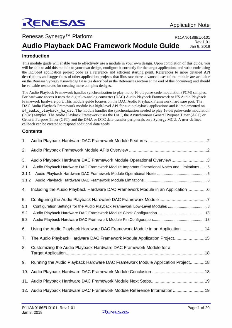
The Audio Playback Framework supports multiple audio streams on a single hardware port. The following figure shows the modules required if two streams are used.

Renesas Synergy™ Platform Audio Playback DAC Framework Module Guide
R11AN0186EU0101 Rev.1.01 Page 5 of 20 Jan 8, 2018
Figure 3 Implementing Multiple Audio Streams
3.1 Audio Playback Hardware DAC Framework Module Important Operational Notes and Limitations
3.1.1 Audio Playback Hardware DAC Framework Module Operational Notes Configuring Messages
Use the Messaging Framework configurator on the Messaging tab to configure the messaging framework.
1. Highlight the Audio Playback event class. 2. Add a new subscriber. 3. Select the following configurations.
Make sure the Message Class Instance property is between the Start and End instance. This property is set in the Properties tab of the Audio Playback Framework on the sf_audio_playback module. Thread: Any thread in the application. Start: First audio instance used in application. End: Last audio instance used in application.
4. Highlight the new Subscriber in the Audio Playback Subscribers. Record the Symbol name. 5. Go back to the Threads tab. 6. Highlight the Audio Playback Framework Shared module in HAL/Common. 7. Set the Audio Message Queue Name to the Symbol name from the Audio Playback Subscriber. Using the I2S Implementation
The audio framework I2S hardware port has dependencies on the I2S Driver module. The I2S driver module can be accelerated with DTC (recommended).
Set the ISDE properties for the I2S driver module.

Renesas Synergy™ Platform Audio Playback DAC Framework Module Guide
R11AN0186EU0101 Rev.1.01 Page 6 of 20 Jan 8, 2018
• Set the Audio Clock Frequency (Hertz) to the frequency of the input audio clock used. • Set the Sampling Frequency (Hertz) to the sampling frequency of your audio data. • Set the Data Bits and Word Length to 16 bits (audio framework accepts 16-bit samples only). • Enable the SSIn TXI and SSIn INT interrupts. Recommended: The transfer module on r_dtc is added automatically.
Using the DAC Implementation
• The Queue used must match the name specified in Properties for Audio Playback Framework Shared on sf_audio_playback (default is g_sf_audio_playback_queue).
• The audio framework DAC hardware port has dependencies on the Timer, DAC, and Transfer API modules. • Timer module.
Set the Frequency in Hz to the sampling frequency of your audio data. Enable the interrupt if using DTC as the transfer module (recommended).
• Transfer module on r_dtc. Set the Destination pointer to &R_DAC->DADRn[0] if using DAC channel 0 or &R_DAC->DADRn[1], if
using DAC channel 1. Set the Activation source to the timer interrupt chosen above.
• The Audio Playback Framework is designed to support the following MCU families with no changes to the API: S7G2 S3A7 S124
Other Operational Notes
The buffer used for the playback should not be more than 2048 bytes
3.1.2 Audio Playback Hardware DAC Framework Module Limitations Refer to the most recent SSP Release Notes for any additional operational limitations for this module.
4. Including the Audio Playback Hardware DAC Framework Module in an Application
To include the Audio Playback Hardware Framework module in an application using the SSP configurator, use the following instructions.
Note: It is assumed you are familiar with creating a project, adding threads, adding a stack to a thread and configuring a block within the stack. If you are unfamiliar with any of these items, see the SSP User’s Manual to learn how to manage each of these important steps in creating SSP-based applications.
To add the Audio Playback Framework to your application, simply add it to a project thread using the stacks selection sequence given in the following table. (The default name for the Audio Playback Hardware Framework is g_sf_audio_playback The default name can be changed in the associated Properties window.)
Table 3 Audio Playback Framework Module Selection Sequence
Resource ISDE Tab Stacks Selection Sequence g_sf_audio_playback Audio Playback Framework on g_sf_audio_playback
Threads New Stack> Framework> Audio> Audio Playback Framework on g_sf_audio_playback
g_sf_audio_playback_hw Audio Playback Hardware Framework Shared on sf_audio_playback_hw_dac
Threads Add Audio Playback Hardware > Audio Playback Hardware Framework Shared on sf_audio_playback_hw_dac
The following figures show when the Audio Playback Hardware Framework module on sf_audio_playback is added to the thread stack, the configurator automatically adds any needed lower-level drivers. Any drivers needing configuration information are highlighted in red. Modules with a gray band are individual, standalone modules. Modules with a blue band are shared or common and need to be added only once to be used by multiple stacks. Modules with a pink band can require selecting of lower-level drivers; these drivers are either optional or recommended (indicated by text in the block). If additional lower-level drivers are required, the module description includes “Add” in the text. Clicking any pink-banded modules brings up the “New” icon and displays possible choices.

Renesas Synergy™ Platform Audio Playback DAC Framework Module Guide
R11AN0186EU0101 Rev.1.01 Page 7 of 20 Jan 8, 2018
Figure 4 Audio Playback Framework Module Stack
Figure 5 Audio Playback Hardware DAC Framework Module Stack
5. Configuring the Audio Playback Hardware DAC Framework Module You configure the Audio Playback Hardware DAC Framework module to the desired operation. The SSP configuration window automatically identifies (by highlighting the block in red) any required configuration for lower-level modules, such as interrupts or operating modes, needed for successful operation. Only properties that can be changed without causing conflicts are available. Other properties are unavailable for modification and ‘locked’ with a lock icon in the ISDE Properties window to indicate the ‘locked’ property. This approach simplifies the configuration process and makes it much less error-prone than previous ‘manual’ approaches. The available configuration settings and the defaults for all the user-accessible properties are displayed in the Properties tab within the SSP configurator, and are also listed in the following tables for easy reference.

Renesas Synergy™ Platform Audio Playback DAC Framework Module Guide
R11AN0186EU0101 Rev.1.01 Page 8 of 20 Jan 8, 2018
One of the properties that often needs changing is the interrupt priority; this configuration setting is available within the Properties window of the associated module. Simply select the module and view the Properties window; the interrupt settings are usually near the bottom of the properties list, so scroll down until they become available. Notice that the interrupt priorities listed in the ISDE Properties window indicates the validity of the setting based on the MCU targeted (CM4 or CM0+). This level of detail is not in the following configuration properties tables, but is easily visible within the ISDE when configuring interrupt-priority levels.
Note: You may want to open your ISDE, create the module, and explore the property settings in parallel with reviewing the following configuration table settings. This helps to orient you and can be a useful ‘hands-on’ approach to learning the ins and outs of developing with SSP.
Table 4 Configuration Settings for the Audio Playback Framework Module on sf_audio_playback
ISDE Property Value Description Parameter Checking BSP, Enabled, Disabled
Default: BSP Enables or disables the parameter checking.
Buffer Size Bytes 512 Buffer size bytes selection. Maximum Number of Streams 1 Maximum number of streams selection. Thread Stack Size 512 Thread stack size selection. Name g_sf_audio_playback0 Module name. Message Class Instance 0 Message class instance selection. Callback NULL Callback selection. Name of generated initialization function
sf_audio_playback_init0 Name of generated initialization function selection
Auto Initialization Enable, Disable Default: Enable
Auto initialization selection
Note: The example settings and defaults are for a project using the Synergy S7G2. Other MCUs may have different default values and available configuration settings.
In some cases, settings other than the defaults for lower-level modules can be desirable. For example, it might be useful to select the DAC Channel based on the target hardware implementation. For completeness, and as a reference, configurable properties for lower-level stack modules are provided in the following subsections.
Note: Most property settings for lower-level modules are intuitive and usually can be determined by inspection of the associated properties window from the SSP configurator.
5.1 Configuration Settings for the Audio Playback Framework Low-Level Modules
Typically, only a small number of settings are modified from the default for lower-level drivers, as the red text in the thread stack block indicates. Notice that some configuration properties must be set to a certain value for proper framework operation and are locked to prevent user modification. The following table identifies all the settings within the properties section for the module.
Table 5 Configuration Settings for the Audio Playback Framework Shared on sf_audio_playback_common
ISDE Property Value Description Name g_sf_audio_playback_common0 Module name Thread Priority 3 Priority for the thread (do not edit) Audio Message Queue Name g_sf_audio_playback_queue Message Queue name
Note: The example values and defaults are for a project using the Synergy SK-S7G2. Other MCUs may have different default values and available configuration settings.

Renesas Synergy™ Platform Audio Playback DAC Framework Module Guide
R11AN0186EU0101 Rev.1.01 Page 9 of 20 Jan 8, 2018
Table 6 Configuration Settings for the Messaging Framework on sf_message
ISDE Property Value Description Parameter Checking BSP, Enabled,
Disabled Default: BSP
Enables or disables the parameter checking.
Message Queue Depth (Total number of messages to be enqueued in a Message Queue)
16 Specify the size of Thread X Message Queue in bytes for Message Subscribers. This value is applied to all the Message Queues.
Name g_sf_message0 The name of Messaging Framework module control block instance.
Work memory size in bytes 2048 Specify the work memory size in bytes. Choosing a small number results a small number of buffers which can be allocated at the same time (You can confirm the total buffer number on: sf_message_ctrl_t::number_of_buffers). If the value is smaller than the peak number of messages to be posted at the same time, the Framework occurs a buffer allocation failure affecting system performance.
Pointer to subscriber list array p_subscriber_lists Specify the name of pointer to the Subscriber List array.
name of the block pool internally used in the messaging framework
sf_msg_blk_pool The name of memory block memory the Framework creates in the control block. This parameter might be useful for debugging purpose but NULL can be specified for saving memory.
Note: The example values and defaults are for a project using the Synergy S7G2. Other MCUs may have different default values and available configuration settings.
Table 7 Configuration Settings for the Audio Playback Hardware Framework Shared on
sf_audio_playback_hw_dac
ISDE Property Value Description Parameter Checking BSP, Enabled, Disabled
Default: BSP Enables or disables the parameter checking.
DMAC Support Disabled, Enabled Default: Disabled
DMAC support selection.
Name g_sf_audio_playback_hw0 Module name. Note: The example values and defaults are for a project using the Synergy S7G2. Other MCUs may have
different default values and available configuration settings. Table 8 Configuration Settings for the DMAC HAL Module on r_dmac Software Activation
ISDE Property Value Description Parameter Checking BSP, Enabled, Disabled
Default: BSP Selects if code for parameter checking is to be included in the build
Name g_transfer0 Module name Channel 0 Channel selection Mode Normal Mode selection Transfer Size 2 Bytes Transfer size selection Destination Address Mode
Fixed Destination address mode selection
Source Address Mode Incremented Source address mode selection Repeat Area (Unused in Normal Mode
Source Repeat area selection
Destination Pointer NULL Destination pointer selection Source Pointer NULL Source pointer selection

Renesas Synergy™ Platform Audio Playback DAC Framework Module Guide
R11AN0186EU0101 Rev.1.01 Page 10 of 20 Jan 8, 2018
ISDE Property Value Description Number of Transfers 0 Number of transfers selection Number of Blocks (Valid only in Block Mode)
0 Number of blocks selection
Activation Source Software Activation, Peripheral Events Default: Software Activation
Activation source selection
Auto Enable False Auto enable selection
Callback NULL Callback selection Interrupt Priority Priority 0 (highest), Priority 1:2,
Priority 3 (CM4: valid, CM0+: lowest- not valid if using ThreadX), Priority 4:14 (CM4: valid, CM0+: invalid), Priority 15 (CM4 lowest - not valid if using ThreadX, CM0+: invalid) Default: Disabled
Interrupt priority selection
Note: The example values and defaults are for a project using the Synergy SK-S7G2. Other MCUs may have different default values and available configuration settings.
Table 9 Configuration Settings for the DTC HAL Module on r_dtc Software Activation 1
ISDE Property Value Description Parameter Checking BSP, Enabled, Disabled
Default: BSP Selects whether code for parameter checking is to be included in the build
Software Start Enabled, Disabled Default: Disabled
Software start selection
Linker section to keep DTC vector table
.ssp_dtc_vector_table Linker section selection
Name g_transfer0 Module name Mode Normal Mode selection Transfer Size 2 Bytes Transfer size selection Destination Address Mode Fixed Destination address mode selection Source Address Mode Incremented Source address mode selection Repeat Area (Unused in Normal Mode
Source Repeat area selection
Interrupt Frequency After all transfers have completed Interrupt frequency selection Destination Pointer NULL Destination pointer selection Source Pointer NULL Source pointer selection Number of Transfers 0 Number of transfers selection Number of Blocks (Valid only in Block Mode)
0 Number of blocks selection
Activation Source (Must enable IRQ)
Software Activation 1, Software Activation 2, Peripheral Events Default: Software Activation 1
Activation source selection
Auto Enable False Auto enable selection Callback (Only valid with Software start)
NULL Callback selection
ELC Software Event Interrupt Priority
Priority 0 (highest), Priority 1:2, Priority 3 (CM4: valid, CM0+: lowest- not valid if using ThreadX), Priority 4:14 (CM4: valid, CM0+: invalid), Priority 15 (CM4 lowest - not valid if using ThreadX, CM0+: invalid) Default: Disabled
ELC Software Event interrupt priority selection.
Note: The example values and defaults are for a project using the Synergy S7G2. Other MCUs may have different default values and available configuration settings.

Renesas Synergy™ Platform Audio Playback DAC Framework Module Guide
R11AN0186EU0101 Rev.1.01 Page 11 of 20 Jan 8, 2018
Table 10 Configuration Settings for the AGT HAL Module on r_agt
ISDE Property Value Description Parameter Checking
BSP, Enabled, Disabled Default: BSP
Enables or disables parameter checking.
Name g_timer0 Module name. Channel 0 Physical hardware channel. Mode Periodic Warning: One Shot functionality is not
available in the GPT hardware; it is implemented in software by stopping the timer in the interrupt service routine (ISR) called when the period expires. For this reason, any ISRs must be enabled for one-shot mode even if the callback is unused.
Period Value 10 See Timer Period Calculation. Period Unit Hertz See Timer Period Calculation. Auto Start FALSE Set to true to start the timer after configuring,
or false to leave the timer stopped until timer_api_t::start is called.
Count Source PCLKB, PCLKB/8, PCLKB/2, LOCO, AGT0 Underflow, AGT0 fSub Default: PCLKB
The clock source for the AGT counter.
AGTO Output Enabled
True, False Default: False
Set to true to output the timer signal on a port pin configured for AGT (AGTO pin). Set to false for no output of the timer signal.
AGTIO Output Enabled
True, False Default: False
Set to true to output the timer signal on a port pin configured for AGT (AGTIO pin). Set to false for no output of the timer signal.
Output Inverted True, False Default: False
Set to false to start the output signal low. Set to true to start the output signal high.
Callback NULL A user callback function can be registered in timer_api_t::open. If this callback function is provided, it is called from the ISR each time the timer period elapses. Warning: Since the callback is called from an ISR, care should be taken not to use blocking calls or lengthy processing. Spending excessive time in an ISR can affect the responsiveness of the system.
Interrupt Priority Priority 0 (highest), Priority 1:2, Priority 3 (CM4: valid, CM0+: lowest- not valid if using ThreadX), Priority 4:14 (CM4: valid, CM0+: invalid), Priority 15 (CM4 lowest - not valid if using ThreadX, CM0+: invalid) Default: Disabled
Timer interrupt priority. 0 is the highest priority.
Note: The example values and defaults are for a project using the Synergy S7G2. Other MCUs may have different default values and available configuration settings.

Renesas Synergy™ Platform Audio Playback DAC Framework Module Guide
R11AN0186EU0101 Rev.1.01 Page 12 of 20 Jan 8, 2018
Table 11 Configuration Settings for the GPT HAL Module on r_gpt
ISDE Property Value Description Parameter Checking
BSP, Enabled, Disabled Default: BSP
Enables or disables the parameter checking.
Name g_timer0 Module name. Channel 0 Channel selection. Mode Periodic Warning: One-shot functionality is not available in the
GPT hardware; it is implemented in software by stopping the timer in the ISR called when the period expires. For this reason, ISR’s must be enabled for one-shot mode even if the callback is unused.
Period Value 10 See Timer Period Calculation Period Unit Hertz See Timer Period Calculation Duty Cycle Value 50 Duty cycle value selection Duty Cycle Unit Unit Raw Counts, Unit
Percent, Unit Percent x 1000 Default: Unit Raw Counts
Duty cycle unit selection
Auto Start FALSE Set to true to start the timer after configuring or false to leave the timer stopped until timer_api_t::start is called.
GTIOCA Output Enabled
True, False Default: False
Set to true to output the timer signal on a port pin configured for GPT. Set to false for no output of the timer signal.
GTIOCA Stop Level
Pin Level Low, Pin Level High, Pin Level Retained Default: Pin Level Low
Controls output pin level when the timer is stopped.
GTIOCB Output Enabled
True, False Default: False
Set to true to output the timer signal on a port pin configured for GPT. Set to false for no output of the timer signal.
GTIOCB Stop Level
Pin Level Low, Pin Level High, Pin Level Retained Default: Pin Level Low
Controls output pin level when the timer is stopped.
Callback NULL A user callback function can be registered in timer_api_t::open. If this callback function is provided, it will be called from the ISR each time the timer period elapses. Warning: Since the callback is called from an ISR, care should be taken not to use blocking calls or lengthy processing. Spending excessive time in an ISR can affect the responsiveness of the system.
Interrupt Priority Priority 0 (highest), Priority 1:2, Priority 3 (CM4: valid, CM0+: lowest- not valid if using ThreadX), Priority 4:14 (CM4: valid, CM0+: invalid), Priority 15 (CM4 lowest - not valid if using ThreadX, CM0+: invalid) Default: Disabled
Interrupt priority selection
Note: The example values and defaults are for a project using the Synergy S7G2. Other MCUs may have different default values and available configuration settings.

Renesas Synergy™ Platform Audio Playback DAC Framework Module Guide
R11AN0186EU0101 Rev.1.01 Page 13 of 20 Jan 8, 2018
Table 12 Configuration Settings for the DAC HAL Module on r_dac
ISDE Property Value Description Parameter Checking BSP, Enabled,
Disabled Default: BSP
Enable or disable the parameter error checking.
Name g_dac0 Module name. Channel 0 Set to 0 for output DA0 or 1 for output DA1. Synchronize with ADC Enabled, Disabled
Default: Disabled Set to true for anti-interference synchronization with the Analog-to-Digital Converter (ADC) Module. Set to false if power supply interference between the analog modules is not a problem, or if asynchronous conversion by the DAC Module is desired.
Data Format Right Justified Set to zero, if 12-bit data values are loaded in bits 11 through 0, or right justified. Set to one, if 12-bit data values are loaded in bits 15 through 4, or left justified.
Output Amplifier Enable, Disable Default: Disable
Set to true, if output amplifier hardware function is desired. Set to false to bypass output amplifier hardware function.
Note: The example values and defaults are for a project using the Synergy S7G2. Other MCUs may have different default values and available configuration settings.
Table 13 Configuration Settings for the DAC8 HAL Module on r_dac8
ISDE Property Value Description
Parameter Checking BSP, Enabled, Disabled Default: BSP
Enable or disable the parameter error checking.
Name g_dac8_0 Module name Channel 0 Channel selection Synchronize with ADC Enabled, Disabled
Default: Disabled Choose whether to sync with the ADC module
Data Format Right Justified, Left Justified Default: Right Justified
Data format selection
DAC Mode Normal Mode, Real-time (Event Link) Mode Default: Normal Mode
DAC mode selection
Charge Pump Enabled (Requires MOCO active)
Enabled, Disabled Default: Enabled
Enable or disable the charge pump
Note: The example values and defaults are for a project using the Synergy S7G2. Other MCUs may have different default values and available configuration settings.
5.2 Audio Playback Hardware DAC Framework Module Clock Configuration The Audio Playback Framework hardware modules (DAC) use the peripheral clocks available in the Clocks configuration window.
5.3 Audio Playback Hardware DAC Framework Module Pin Configuration The DAC or SSI peripheral module uses pins on the MCU to communicate to external devices. Select and configure these I/O pins as required by the external device. The following table lists how to select the pins within the SSP configuration window and the subsequent table has an example selection for associated pins.
Note: For some peripherals, the operational mode selected determines the peripheral signals available and the MCU pins required.
Renesas Synergy™ Platform Audio Playback DAC Framework Module Guide
R11AN0186EU0101 Rev.1.01 Page 14 of 20 Jan 8, 2018
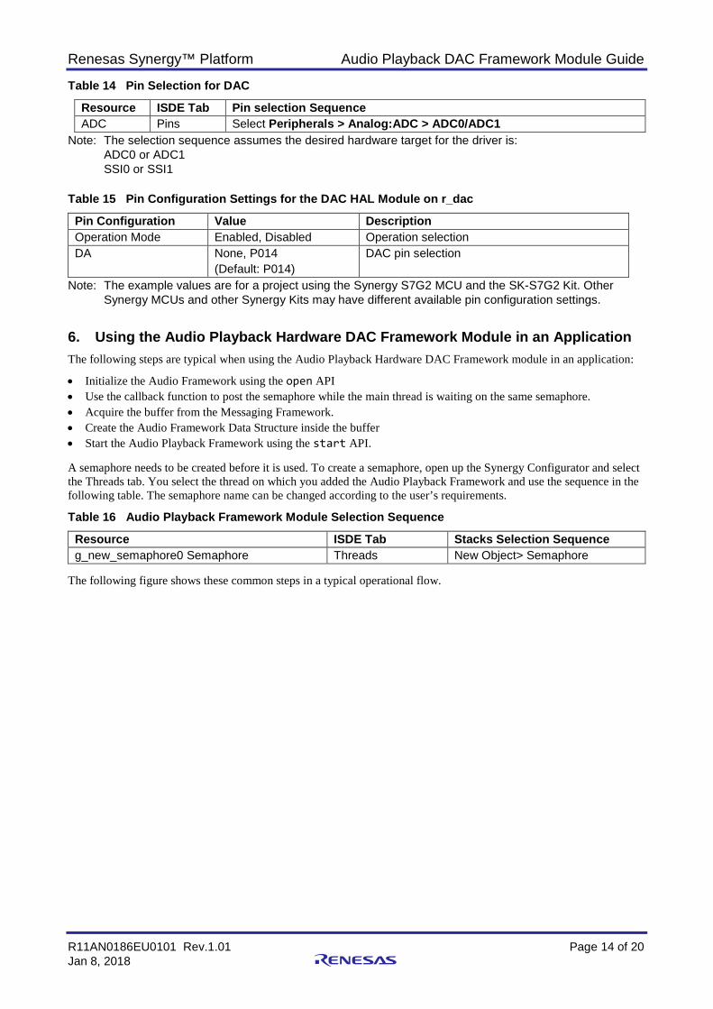
Table 14 Pin Selection for DAC
Resource ISDE Tab Pin selection Sequence ADC Pins Select Peripherals > Analog:ADC > ADC0/ADC1
Note: The selection sequence assumes the desired hardware target for the driver is: ADC0 or ADC1 SSI0 or SSI1
Table 15 Pin Configuration Settings for the DAC HAL Module on r_dac
Pin Configuration Value Description Operation Mode Enabled, Disabled Operation selection DA None, P014
(Default: P014) DAC pin selection
Note: The example values are for a project using the Synergy S7G2 MCU and the SK-S7G2 Kit. Other Synergy MCUs and other Synergy Kits may have different available pin configuration settings.
6. Using the Audio Playback Hardware DAC Framework Module in an Application The following steps are typical when using the Audio Playback Hardware DAC Framework module in an application:
• Initialize the Audio Framework using the open API • Use the callback function to post the semaphore while the main thread is waiting on the same semaphore. • Acquire the buffer from the Messaging Framework. • Create the Audio Framework Data Structure inside the buffer • Start the Audio Playback Framework using the start API. A semaphore needs to be created before it is used. To create a semaphore, open up the Synergy Configurator and select the Threads tab. You select the thread on which you added the Audio Playback Framework and use the sequence in the following table. The semaphore name can be changed according to the user’s requirements.
Table 16 Audio Playback Framework Module Selection Sequence
Resource ISDE Tab Stacks Selection Sequence g_new_semaphore0 Semaphore Threads New Object> Semaphore
The following figure shows these common steps in a typical operational flow.

Renesas Synergy™ Platform Audio Playback DAC Framework Module Guide
R11AN0186EU0101 Rev.1.01 Page 15 of 20 Jan 8, 2018
Figure 6 Typical Audio Playback Hardware DAC Framework module application flow
7. The Audio Playback Hardware DAC Framework Module Application Project The application project associated with this module guide demonstrates these steps in an example application. You may want to import and open the application project within the ISDE and view the configuration settings for the Audio Playback Hardware DAC Framework module. The project can be found using the link provided in the References section at the end of this document. You can also read over the code in audio_playback_thread_entry.c that is used to demonstrate the Audio Playback APIs in a complete design.
This application project shows the typical use of the Audio Playback APIs. The main thread entry initializes the Audio Playback Framework and plays the RAW PCM file on flash memory. The playback framework gets information from the Messaging Framework and stores this data in the audio buffer. Stream-related information is in the audio.c file. The following table lists target versions for the associated software and hardware used by the application project:
Table 17 Software and Hardware Resources Used by the Application Project
Resource Revision Description e2 studio 5.3.1 or later Integrated Solution Development Environment SSP 1.2.0 or later Synergy Software Platform
IAR EW for Renesas Synergy 7.71.2 or later IAR Embedded Workbench® for Renesas Synergy™
SSC 5.3.1 or later Synergy Standalone Configurator SK-S7G2 V3.0 to v3.1 Starter Kit
The following figure shows a simple flow of the application project.

Renesas Synergy™ Platform Audio Playback DAC Framework Module Guide
R11AN0186EU0101 Rev.1.01 Page 16 of 20 Jan 8, 2018
Figure 7 Audio Playback Hardware DAC Framework Module Application Project Flow
The complete application project can be found using the link in the References section at the end of this document.
The audio_playback_hw_dac_control.c file is in the application project once it has been imported into the ISDE. The project also includes the application_define.h and audio_data.c files. You can open these files from the ISDE and follow along to help learn key uses of the APIs.
The first section of audio_playback_hw_dac_control.c has the header files referencing the audio playback framework instance structure and structure for basic information about the PCM stream and payload for sf_audio_playback. An audio callback function next executes a post of the previously created semaphore (g_sf_audio_playback_sem). The callback function executes when the audio playback framework is done with the data.
The next audio_playback_thread_entry.c file section is the entry function for the main program control section. The application uses the on-board push buttons S4 and S5 to control the audio playback. The application pends for a user input – external IRQ – generated by pressing the on-board push button S4 – before playing the audio data. After successfully receiving the external IRQ event, a local variable is updated with the stream-related information. The GPT’s periodSet API is called to set the period of the timer to the sample period of the audio stream. Thereafter, it acquires the semaphore g_sf_audio_playback_sem before starting to play data. After acquiring this semaphore, the main program control acquires a buffer from the messaging framework, and copies the audio playback data into the buffer. Playback is started by calling the .start API.
The on-board pushbutton S4 is used to start and stop playback. The .stop API is used to stop the playback. Pushbutton S5 is used to change the volume of the playback. Volume is changed by using the volumeSet API. Each press of S5 decreases the volume by 50. If the volume is currently 0, the volume is set to 255, the maximum value.
Note: It is assumed you are familiar with using External IRQ Framework. If you are unfamiliar with this framework, see the SSP User’s Manual. The external IRQ Framework has been used to implement S4 and S5 button press event notification and wait to execute other API functionalities. Currently on this application project, SK-S7G2 button S4 starts and stops the playback stream, while during playback button S5 presses decreases the playback volume because normal playback starts with full volume.
Remember to add the subscriber thread for the Audio event in the Messaging Tab. Highlight the new Subscriber in the Audio Playback Subscribers. Record the Symbol name. Highlight the Audio Playback

Renesas Synergy™ Platform Audio Playback DAC Framework Module Guide
R11AN0186EU0101 Rev.1.01 Page 17 of 20 Jan 8, 2018
Framework Shared module in the HAL/Common in thread tab and set the Audio Message Queue name to the Symbol name from the Audio Playback Subscriber.
A few key properties are configured in this Application Project support the required operations and the physical properties of the target board and MCU. The following tables show properties that are listed with the values set for this specific project. You can also open the Application Project and view these settings in the property window as a hands-on exercise.
Table 18 Audio Playback Framework Module Configuration Settings
ISDE Property Value Set Buffer Size Bytes 8792 Maximum Number of Streams 1 Thread Stack Size 512 Name sf_audio_playback Message Class Instance 0 Callback sf_audio_playback_callback
Table 19 Audio Playback Framework Shared Module Configuration Settings
ISDE Property Value Set Name g_sf_audio_playback_common Thread Priority 3 Audio Message Queue Name audio_playback_thread_message_queue
Table 20 Audio Playback Hardware Framework Shared Module Configuration Settings
ISDE Property Value Set Name g_sf_audio_playback_hw DMAC Support Disabled
Table 21 Transfer Driver Module Configuration Settings
ISDE Property Value Set Name g_audio_transfer Destination Pointer &R_DAC->DADRn [0] Activation Source (Must Enable IRQ) Event GPT0 COUNTER OVERFLOW
Table 22 Timer Driver Module Configuration Settings
ISDE Property Value Set Name g_audio_timer Channel 0 Period Value 44100 Duty Cycle Value 50 Duty Cycle Unit Unit Percent
Table 23 DAC Driver Module Configuration Settings
ISDE Property Value Set Name g_audio_dac Channel 0

Renesas Synergy™ Platform Audio Playback DAC Framework Module Guide
R11AN0186EU0101 Rev.1.01 Page 18 of 20 Jan 8, 2018
Table 24 Semaphore Configuration Settings
ISDE Property Value Set Name Audio Playback Framework Semaphore Symbol g_sf_audio_playback_sem Channel 2
The Messaging Framework also has to be configured. Use the Messaging Framework configurator on the Messaging tab to configure the framework.
8. Customizing the Audio Playback Hardware DAC Framework Module for a Target Application
Some configuration settings are normally changed by the developer from those in the Application Project. For example, you can change the sampling frequency and transfer driver through timer module and transfer driver, respectively. For the transfer driver, you have a choice between the DTC and DMAC.
In the case of the DMAC driver, you should enable the driver interrupt and set its priority to be of a higher value than that of the Audio Playback Hardware Framework module.
This particular Audio Playback HW DAC Framework Application Project uses the on-board S4 and S5 push buttons for user control. The user control can be customized by the user.
9. Running the Audio Playback Hardware DAC Framework Module Application Project
To run the Audio Playback Hardware DAC Framework module application project and to see it executed on a target kit, you can simply import it into your ISDE, compile, and run debug.
To implement the Audio Playback Hardware DAC Framework module application in a new project, use the following steps for defining, configuring, auto-generating files, adding code, compiling and debugging the target kit. Following these steps is a hands-on approach that can help make the development process with SSP more practical, while just reading over this guide tend to be more theoretical.
Note: The following steps are described in sufficient detail for someone experienced with the basic flow through the Synergy development process. If these steps are unfamiliar, see the SSP User’s Manual listed in the References section at the end of this document.
Simply use the following steps to create and run the Audio Playback Hardware DAC Framework module application project.
1. Create a new Renesas Synergy project for the SK-S7G2 called Audio_framework_with_HW_DAC_MG 2. Select the Threads tab. 3. Add a new thread called audio_playback_thread and add the Audio Playback Framework on
sf_audio_playback using the framework>Audio selection path. 4. Add DTC, timer and HW DAC drivers in the given stack. 5. Click the Generate Project Content button. 6. Add the code from the supplied project file audio_playback_thread_entry.c, or copy over the generated
audio_playback_thread_entry.c file. 7. Add the application_define.h and audio_data.c files from the supplied project files. 8. Build the application code and connect the board to flash the executable binary. 9. Execute the application program. 10. The output can be heard on a speaker or a headphone, whichever is connected to the 3.5 mm audio jack on the
SK-S7G2 board. Playback is started when the on-board pushbutton S4 is pressed for the first time. Volume can be set by pressing pushbutton S5 in decrement steps of 50 units.
11. Press S4 again to stop the playback. To restart the playback, press S4 once more.
10. Audio Playback Hardware DAC Framework Module Conclusion This module guide has provided all the background information needed to select, add, configure, and use the module in an example project. Many of these steps were time-consuming and error-prone activities in previous generations of embedded systems. The Renesas Synergy Platform makes these steps less time consuming and removes common errors, like conflicting configuration settings or incorrect selection of low-level drivers. The use of high-level APIs (as

Renesas Synergy™ Platform Audio Playback DAC Framework Module Guide
R11AN0186EU0101 Rev.1.01 Page 19 of 20 Jan 8, 2018
demonstrated in the application project) showcases the development time savings in allowing work to begin at a high level, avoiding the time required in older development environments to use or, in some cases, create lower-level drivers.
11. Audio Playback Hardware DAC Framework Module Next Steps After you have mastered a simple Audio Playback Framework with DAC driver project, you may want to review a more complex example. You may find that the Audio Playback Framework is a better fit for your target application. The Audio Playback Framework with DAC driver Module Guide demonstrates the use of the Audio Framework within a ThreadX-based implementation on the DAC driver. This guide is available at the link shown in the References section at the end of this document.
12. Audio Playback Hardware DAC Framework Module Reference Information SSP User Manual: Available in html format in the SSP distribution package and as a pdf from the Synergy Gallery.
Links to all the most up-to-date Audio Playback Hardware DAC Framework module reference materials and resources are available on the Synergy Knowledge Base: https://en-us.knowledgebase.renesas.com/English_Content/Renesas_Synergy%E2%84%A2_Platform/Renesas_Synergy_Knowledge_Base/SF_Audio_Playback_HW_DAC_Module_Guide_Resources.
Renesas Synergy™ Platform Audio Playback DAC Framework Module Guide
R11AN0186EU0101 Rev.1.01 Page 20 of 20 Jan 8, 2018
Website and Support Support: https://synergygallery.renesas.com/support
Technical Contact Details:
• America: https://www.renesas.com/en-us/support/contact.html • Europe: https://www.renesas.com/en-eu/support/contact.html • Japan: https://www.renesas.com/ja-jp/support/contact.html
All trademarks and registered trademarks are the property of their respective owners.

Revision History
Rev. Date Description Page Summary
1.00 Jun 14, 2017 - Version 1.0 1.01 Jan 8, 2018 - Update to Hardware and Software Resources Table

http://www.renesas.comRefer to "http://www.renesas.com/" for the latest and detailed information.
Renesas Electronics America Inc.1001 Murphy Ranch Road, Milpitas, CA 95035, U.S.A.Tel: +1-408-432-8888, Fax: +1-408-434-5351Renesas Electronics Canada Limited9251 Yonge Street, Suite 8309 Richmond Hill, Ontario Canada L4C 9T3Tel: +1-905-237-2004Renesas Electronics Europe LimitedDukes Meadow, Millboard Road, Bourne End, Buckinghamshire, SL8 5FH, U.KTel: +44-1628-651-700, Fax: +44-1628-651-804Renesas Electronics Europe GmbHArcadiastrasse 10, 40472 Düsseldorf, GermanyTel: +49-211-6503-0, Fax: +49-211-6503-1327Renesas Electronics (China) Co., Ltd.Room 1709 Quantum Plaza, No.27 ZhichunLu, Haidian District, Beijing, 100191 P. R. ChinaTel: +86-10-8235-1155, Fax: +86-10-8235-7679Renesas Electronics (Shanghai) Co., Ltd.Unit 301, Tower A, Central Towers, 555 Langao Road, Putuo District, Shanghai, 200333 P. R. ChinaTel: +86-21-2226-0888, Fax: +86-21-2226-0999Renesas Electronics Hong Kong LimitedUnit 1601-1611, 16/F., Tower 2, Grand Century Place, 193 Prince Edward Road West, Mongkok, Kowloon, Hong KongTel: +852-2265-6688, Fax: +852 2886-9022Renesas Electronics Taiwan Co., Ltd.13F, No. 363, Fu Shing North Road, Taipei 10543, TaiwanTel: +886-2-8175-9600, Fax: +886 2-8175-9670Renesas Electronics Singapore Pte. Ltd.80 Bendemeer Road, Unit #06-02 Hyflux Innovation Centre, Singapore 339949Tel: +65-6213-0200, Fax: +65-6213-0300Renesas Electronics Malaysia Sdn.Bhd.Unit 1207, Block B, Menara Amcorp, Amcorp Trade Centre, No. 18, Jln Persiaran Barat, 46050 Petaling Jaya, Selangor Darul Ehsan, MalaysiaTel: +60-3-7955-9390, Fax: +60-3-7955-9510Renesas Electronics India Pvt. Ltd.No.777C, 100 Feet Road, HAL 2nd Stage, Indiranagar, Bangalore 560 038, IndiaTel: +91-80-67208700, Fax: +91-80-67208777Renesas Electronics Korea Co., Ltd.17F, KAMCO Yangjae Tower, 262, Gangnam-daero, Gangnam-gu, Seoul, 06265 KoreaTel: +82-2-558-3737, Fax: +82-2-558-5338
SALES OFFICES
© 2018 Renesas Electronics Corporation. All rights reserved.Colophon 7.0
(Rev.4.0-1 November 2017)
Notice1. Descriptions of circuits, software and other related information in this document are provided only to illustrate the operation of semiconductor products and application examples. You are fully responsible for
the incorporation or any other use of the circuits, software, and information in the design of your product or system. Renesas Electronics disclaims any and all liability for any losses and damages incurred by
you or third parties arising from the use of these circuits, software, or information.
2. Renesas Electronics hereby expressly disclaims any warranties against and liability for infringement or any other claims involving patents, copyrights, or other intellectual property rights of third parties, by or
arising from the use of Renesas Electronics products or technical information described in this document, including but not limited to, the product data, drawings, charts, programs, algorithms, and application
examples.
3. No license, express, implied or otherwise, is granted hereby under any patents, copyrights or other intellectual property rights of Renesas Electronics or others.
4. You shall not alter, modify, copy, or reverse engineer any Renesas Electronics product, whether in whole or in part. Renesas Electronics disclaims any and all liability for any losses or damages incurred by
you or third parties arising from such alteration, modification, copying or reverse engineering.
5. Renesas Electronics products are classified according to the following two quality grades: “Standard” and “High Quality”. The intended applications for each Renesas Electronics product depends on the
product’s quality grade, as indicated below.
"Standard": Computers; office equipment; communications equipment; test and measurement equipment; audio and visual equipment; home electronic appliances; machine tools; personal electronic
equipment; industrial robots; etc.
"High Quality": Transportation equipment (automobiles, trains, ships, etc.); traffic control (traffic lights); large-scale communication equipment; key financial terminal systems; safety control equipment; etc.
Unless expressly designated as a high reliability product or a product for harsh environments in a Renesas Electronics data sheet or other Renesas Electronics document, Renesas Electronics products are
not intended or authorized for use in products or systems that may pose a direct threat to human life or bodily injury (artificial life support devices or systems; surgical implantations; etc.), or may cause
serious property damage (space system; undersea repeaters; nuclear power control systems; aircraft control systems; key plant systems; military equipment; etc.). Renesas Electronics disclaims any and all
liability for any damages or losses incurred by you or any third parties arising from the use of any Renesas Electronics product that is inconsistent with any Renesas Electronics data sheet, user’s manual or
other Renesas Electronics document.
6. When using Renesas Electronics products, refer to the latest product information (data sheets, user’s manuals, application notes, “General Notes for Handling and Using Semiconductor Devices” in the
reliability handbook, etc.), and ensure that usage conditions are within the ranges specified by Renesas Electronics with respect to maximum ratings, operating power supply voltage range, heat dissipation
characteristics, installation, etc. Renesas Electronics disclaims any and all liability for any malfunctions, failure or accident arising out of the use of Renesas Electronics products outside of such specified
ranges.
7. Although Renesas Electronics endeavors to improve the quality and reliability of Renesas Electronics products, semiconductor products have specific characteristics, such as the occurrence of failure at a
certain rate and malfunctions under certain use conditions. Unless designated as a high reliability product or a product for harsh environments in a Renesas Electronics data sheet or other Renesas
Electronics document, Renesas Electronics products are not subject to radiation resistance design. You are responsible for implementing safety measures to guard against the possibility of bodily injury, injury
or damage caused by fire, and/or danger to the public in the event of a failure or malfunction of Renesas Electronics products, such as safety design for hardware and software, including but not limited to
redundancy, fire control and malfunction prevention, appropriate treatment for aging degradation or any other appropriate measures. Because the evaluation of microcomputer software alone is very difficult
and impractical, you are responsible for evaluating the safety of the final products or systems manufactured by you.
8. Please contact a Renesas Electronics sales office for details as to environmental matters such as the environmental compatibility of each Renesas Electronics product. You are responsible for carefully and
sufficiently investigating applicable laws and regulations that regulate the inclusion or use of controlled substances, including without limitation, the EU RoHS Directive, and using Renesas Electronics
products in compliance with all these applicable laws and regulations. Renesas Electronics disclaims any and all liability for damages or losses occurring as a result of your noncompliance with applicable
laws and regulations.
9. Renesas Electronics products and technologies shall not be used for or incorporated into any products or systems whose manufacture, use, or sale is prohibited under any applicable domestic or foreign laws
or regulations. You shall comply with any applicable export control laws and regulations promulgated and administered by the governments of any countries asserting jurisdiction over the parties or
transactions.
10. It is the responsibility of the buyer or distributor of Renesas Electronics products, or any other party who distributes, disposes of, or otherwise sells or transfers the product to a third party, to notify such third
party in advance of the contents and conditions set forth in this document.
11. This document shall not be reprinted, reproduced or duplicated in any form, in whole or in part, without prior written consent of Renesas Electronics.
12. Please contact a Renesas Electronics sales office if you have any questions regarding the information contained in this document or Renesas Electronics products.
(Note 1) “Renesas Electronics” as used in this document means Renesas Electronics Corporation and also includes its directly or indirectly controlled subsidiaries.
(Note 2) “Renesas Electronics product(s)” means any product developed or manufactured by or for Renesas Electronics.