Embed Size (px)
Citation preview


Audel™
Pipefitter’s and Welder’sPocket Manual
All New Second Edition
Charles N. McConnell


Audel™
Pipefitter’s and Welder’sPocket Manual


Audel™
Pipefitter’s and Welder’sPocket Manual
All New Second Edition
Charles N. McConnell

Publisher: Joe WikertSenior Editor: Katie FeltmanDevelopmental Editor: Kevin ShaferEditorial Manager: Kathryn A. MalmProduction Editor: Pamela M. HanleyText Design & Composition: TechBooks
Copyright© 2003 by Wiley Publishing, Inc. All rights reserved.Copyright© 1997 by Charles N. McConnell.
Published simultaneously in Canada
No part of this publication may be reproduced, stored in a retrieval system, or transmittedin any form or by any means, electronic, mechanical, photocopying, recording, scanning,or otherwise, except as permitted under Section 107 or 108 of the 1976 United StatesCopyright Act, without either the prior written permission of the Publisher, or authoriza-tion through payment of the appropriate per-copy fee to the Copyright Clearance Center,Inc., 222 Rosewood Drive, Danvers, MA 01923, (978) 750-8400, fax (978) 646-8700.Requests to the Publisher for permission should be addressed to the Legal Department,Wiley Publishing, Inc., 10475 Crosspoint Blvd., Indianapolis, IN 46256, (317) 572-3447,fax (317) 572-4447, E-mail: [email protected].
Limit of Liability/Disclaimer of Warranty: While the publisher and author have used theirbest efforts in preparing this book, they make no representations or warranties with respectto the accuracy or completeness of the contents of this book and specifically disclaim anyimplied warranties of merchantability or fitness for a particular purpose. No warrantymay be created or extended by sales representatives or written sales materials. The adviceand strategies contained herein may not be suitable for your situation. You should consultwith a professional where appropriate. Neither the publisher nor author shall be liable forany loss of profit or any other commercial damages, including but not limited to special,incidental, consequential, or other damages.
For general information on our other products and services please contact our CustomerCare Department within the United States at (800) 762-2974, outside the United States at(317) 572-3993 or fax (317) 572-4002.
Trademarks: Wiley, the Wiley Publishing logo, Audel, and related trade dress are trade-marks or registered trademarks of John Wiley & Sons, Inc. and/or its affiliates. All othertrademarks are the property of their respective owners. Wiley Publishing, Inc., is not asso-ciated with any product or vendor mentioned in this book.
Wiley also publishes its books in a variety of electronic formats. Some content that appearsin print may not be available in electronic books.
Library of Congress Cataloging-in-Publication Data:
ISBN: 0-764-54205-2
Printed in the United States of America
10 9 8 7 6 5 4 3 2 1

Contents
1. Math and Metrics 1
2. Calculating Offsets 14
3. Pipe Welding with Oxyacetylene and Arc 34
4. Automatic Fire Protection Systems 55
5. Steam Heating Systems 68
6. Hot-Water Heating Systems 86
7. Air Conditioning and Refrigeration 106
8. Process Piping Using Plastics 142
9. Grooved-End and Plain-End Piping Systems 154
10. Learning to Use an Instrument Level 161
11. Pneumatic Control Systems 169
12. Gas Piping 179
13. Tungsten Inert Gas Welding 194
14. Trouble-Shooting Tips for Arc Welding 209
15. Pipe Welders’ Definitions 214
16. Definitions of Heating and Air Conditioning Terms 217
17. Glossary of Terms Relating to Plastic Piping 228
Appendix: Miscellaneous Information 237
Index 307
v


Chemtrol®, a brand ofNIBCO® Elkhart IN 46515
ITT Fluid Technology 8200 N. Austin Ave.Morton Grove IL 60053
Johnson Controls, Inc.507 E. Michigan StreetP.O. Box 423Milwaukee WI 53201
Kamweld Products Co. Inc.Norwood MA 02062
Powerex150 Production DriveHarrison OH 45030
Redi/Controls, Inc.755 East Main StreetGreenwood IN 46143
Ridge Tool Co.400 Clark StreetElyria OH 44032
Victaulic® Company ofAmericaP.O. Box 31Easton PA 18044-0031
Victor Equipment CompanyA Thermodyne Company2800 Airport RoadDenton TX 76207
The Viking Corporation210 N. Industrial Park RoadHastings MI 49058
Watts RegulatorRte. 114 & Chestnut St.N. Andover MA 01845
Acknowledgments
vii


About the Author
Charles N. McConnell has been a member of the UnitedAssociation of Journeymen and Apprentices of the Plumbing,Pipefitting, Sprinkler Fitting Industry of the United States andCanada for over 60 years and has trained many apprenticesto the piping trades. He has supervised and installed gas andoil-fired steam and hot-water heating systems and air-conditioning installations at Purdue University, Lafayette,Indiana, and plumbing installations in schools, public build-ings, and manufacturing facilities. He has supervised andinstalled process piping installations. He is the author ofHome Plumbing Handbook (Delmar Education), the three-volume Plumbers and Pipefitters Library (Macmillan), andother books related to the plumbing and pipefitting trades.
ix


xi
INTRODUCTION
Choosing a Career The purpose of this book is twofold: (1) to acquaint high-school students with the advantages of a career as a workerin the piping trades, (2) to serve as a reference for workers inthe pipe-fitting trades who encounter problems on the job.
Fortunate indeed is a high-school graduate who hasselected a career to pursue for life. By the second year of highschool, if they have had good guidance from their parentsand/or school counselors, many students who plan to con-tinue their formal education are deciding which college oruniversity to apply to and what kind of courses to enroll in.Are all high-school graduates suitable candidates for college?Not necessarily. Many are still trying to find out who theyare.
As an alternative to college, the author suggests that thehigh-school student consider the many advantages ofapprenticeship training in one of the branches of the pipingtrades. The time to start investigating college scholarshipsand/or apprenticeship programs is during the second year ofhigh school. This book explains the scope of work of variousbranches of the piping trades.
Apprenticeship and Trade Schools
ApprenticeshipApprenticeship offers the best opportunities in on-the-jobpaid training and related classroom instruction. The time tostart apprenticeship is upon graduation from high school.Applicants for union apprenticeship must be at least 18years old and in good physical condition and must have ahigh-school diploma or its equivalent.

The author, a member of the United Association ofJourneymen and Apprentices of the Plumbing, Pipefitting,Sprinkler Fitting Industry of the United States and Canadafor over 60 years, recommends apprenticeship training as aunion member. Local unions train members in all phases ofthe plumbing and pipefitting trades. The value of unionmembership becomes more apparent upon close examina-tion. The surest way to protect one’s wages, health insur-ance, and retirement plan is through union membership.Most apprenticeship programs are fully implemented at thelocal level by the Joint Apprenticeship Committee (JAC) ofthe particular trade.
Unionized construction is one of the few industries in whichmanagement, labor, and government cooperate. Management(the building contractors) assures itself of a pool of trainedqualified workers; labor (the craft unions) maintains a mar-ketable product, the skilled journeyman; and the apprentice isgiven the opportunity to receive excellent vocational trainingat virtually no cost (on-the-job training) and to earn while heor she learns.
Women are accepted as apprentices in the piping trades.Many women have served as apprentices, learned a trade,worked in the field as journeymen, and gone on to open abusiness.
Vocational SchoolsFor those who have missed the opportunity to apply forapprenticeship, there are excellent trade or vocational schools.Upon completion of courses at these schools, graduates shouldbe qualified to pass proficiency tests and obtain licenses in theirtrade. A list of many U.S. and Canadian schools and their loca-tions will be found in the Appendix.
Career OutlookThe piping trades are among the highest-paid constructionoccupations. Apprentices usually begin at 50 percent of the
xii Introduction

wage rate of skilled tradesmen. After an initial waitingperiod, apprentices receive the same benefits as skilledtradesmen. For information about apprenticeship opportu-nities, contact the business manager of the local union ofThe United Association of Journeymen and Apprentices ofthe Plumbing, Pipefitting, Sprinkler Fitting Industry of theUnited States and Canada. For office location, look in thewhite Business listings in your local phone book.
Information is also available from the international head-quarters of: The United Association of Journeymen and Ap-prentices of the Plumbing, Pipefitting, Sprinkler FittingIndustry of the United States and Canada, 901 MassachusettsAve. NW, Washington, DC 20001.
For general information about the work of the pipingtrades, contact:
Mechanical Contractors Association of America1385 Piccard DriveRockville, MD 20850National Association of Plumbing, Heating, CoolingContractors180 S. Washington St.P.O. Box 6808Falls Church, VA 22040
For general information about the work of sprinkler fit-ters, contact:
American Fire Sprinkler Association, Inc.12959 Jupiter Rd.Suite 142Dallas, TX 75238-3200National Fire Sprinkler AssociationRobin Hill Corporate ParkRt. 22, Box 1000Patterson, NY 12563
Introduction xiii

Recommended Reading• The Building Trades and Apprenticeship, What You
Need to Know to Get In! by John Lonergan.• 2002–2003 Career Guide to Industries at local libraries.• On the Internet: Bureau of Labor Statistics, U.S.
Department of Labor, Occupational Outlook Hand-book, 2002–2003 Edition, Pipelayers, Plumbers, Pipe-fitters and Steamfitters at: http://www.bis.gov/oco/ocos211.htm.
xiv Introduction

Audel™
Pipefitter’s and Welder’sPocket Manual


1. MATH AND METRICS
In the not too distant past, a book such as this would havestarted with some basic math: addition, subtraction, multi-plication, and long division. But with today’s apprenticeshipclasses, on-the-job training, and widespread use of calcula-tors, a chapter devoted to basic math is unnecessary.
Quite often, especially on large construction jobs, job con-ditions require that offsets in pipe runs be made. Numberscalled “constants,” taken from trigonometric tables, are usedto calculate offsets. These numbers are shown and explainedin Chapter 2, “Calculating Offsets.”
Many times, problems encountered on the job involvethe use of fractions. Pipefitters seldom, if ever, work withfractions other than 1⁄8, 1⁄4, 3⁄8, 1⁄2, 5⁄8, 3⁄4, and 7⁄8. Using thedecimal equivalents of these fractions is much easier thanusing the fractions themselves. As a memory aid, Table 1-1shows the decimal equivalents of fractions from 1⁄64 to1 inch.
Table 1-1 Decimal Equivalents of Fractions
Inches Decimal Equivalent Inches Decimal Equivalent1⁄64 0.015625 7⁄16 0.43751⁄32 0.03125 29⁄64 0.4531253⁄64 0.046875 15⁄32 0.468751⁄20 0.05 31⁄64 0.4843751⁄16 0.0625 1⁄2 0.51⁄13 0.0769 33⁄64 0.5156255⁄64 0.078125 17⁄32 0.531251⁄12 0.0833 35⁄64 0.5468751⁄11 0.0909 9⁄16 0.56253⁄32 0.09375 37⁄64 0.578125
(continued)
1

2 Math and Metrics
Table 1-1 (continued)
Inches Decimal Equivalent Inches Decimal Equivalent1⁄10 0.10 19⁄32 0.593757⁄64 0.109375 39⁄64 0.6093751⁄9 0.111 5⁄8 0.6251⁄8 0.125 41⁄64 0.6406259⁄64 0.140625 21⁄32 0.656251⁄7 0.1429 43⁄64 0.6718755⁄32 0.15625 11⁄16 0.68751⁄6 0.1667 45⁄64 0.70312511⁄64 0.171875 23⁄32 0.718753⁄16 0.1875 47⁄64 0.7343751⁄5 0.2 3⁄4 0.7513⁄64 0.203125 49⁄64 0.7656257⁄32 0.21875 25⁄32 0.7812515⁄64 0.234375 51⁄64 0.7968751⁄4 0.25 13⁄16 0.812517⁄64 0.265625 53⁄64 0.8281259⁄32 0.28125 27⁄32 0.8437519⁄64 0.296875 55⁄64 0.8593755⁄16 0.3125 7⁄8 0.87521⁄64 0.328125 57⁄64 0.8906251⁄3 0.333 29⁄32 0.9062511⁄32 0.34375 59⁄64 0.92187523⁄64 0.359375 15⁄16 0.93753⁄8 0.375 61⁄64 0.95312525⁄64 0.390625 31⁄32 0.9687513⁄32 0.40625 63⁄64 0.98437527⁄64 0.421875 1 1.0

It is often necessary to find the capacity of a round tank.The more steps involved in solving a problem, the morelikely a person is to make a mistake. The old standardmethod (with tank measured in inches) is:
Formula: D2 � 0.7854 � Length (L) � 231 gallons.(D � D � D2) We’ll use our calculator tosolve these problems.D of Tank � 12 inL � 60 in
Step 1. 12 � 12 (D2) � 144Step 2. 144 � 60 � 8640Step 3. 8640 � 0.7854 � 6785.856Step 4. 6785.856 � 231 � 29.376 gal—(four steps
needed)
Now, let’s use either of two three-step methods with thesame size tank.
Method 1—tank measured in inches.
D � 12 inL � 60 inFormula: D2 � L � 0.0034 gallons
Step 1. 12 � 12 � 144Step 2. 144 � 60 � 8640Step 3. 8640 � 0.0034 � 29.376
NoteThe answer is the same, but one less step is needed, thusthere is less chance of a mistake.
Math and Metrics 3

4 Math and Metrics
Method 2—with tank measured in inches and feet.
D � 12 inL � 5 ft
Formula: D2 � L � 0.0408 � gallons
Step 1. 12 � 12 � 144Step 2. 144 � 5 � 720Step 3. 720 � 0.0408 � 29.376
NoteHere again, the answer is the same as in the other methods,with one less step needed. As a result, there is less chance ofmaking a mistake.
The above methods can also be used to find the liquidcapacity of piping. In the example below, use Method 2.
ExampleHow many gallons of foam-water concentrate solution willbe needed to fill the following pipe footage?
200 ft of 6� fire main500 ft of 4� fire main200 ft of 1� drops to sprinkler heads
Using Method 2, we find:
6 in 6 � 6 � 200 � 0.0408 � 293.76 gal4 in 4 � 4 � 500 � 0.0408 � 326.40 gal1 in 1 � 1 � 200 � 0.0408 � 8.16 gal
Total gallons needed 628.32 gal
The above formulas can be used in many other calcula-tions performed by pipefitters.
Table 1-2 is provided as a quick reference for multiplyingnumbers from 1 to 25.

Math and Metrics 5Ta
ble
1-2
Mul
tipl
icat
ion
Tabl
e
No
�1
�2
�3
�4
�5
�6
�7
�8
�9
�10
�11
�12
�13
�14
�15
11
23
45
67
89
1011
1213
1415
22
46
81 0
1 21 4
1 61 8
2 02 2
2 42 6
2 83 0
33
69
1215
1821
2427
3033
3639
4245
44
812
1620
2428
3236
4044
4852
5660
55
1015
2025
3035
4045
5055
6065
7075
66
1218
2430
3642
4854
6066
7278
8490
77
1421
2835
4249
5663
7077
8491
9810
5
88
1624
3240
4856
6472
8088
9610
411
212
0
99
1827
3645
5463
7281
9099
108
117
126
135
1010
2030
4050
6070
8090
100
110
120
130
140
150
1111
2233
4455
6677
8899
110
121
132
143
154
165
1212
2436
4860
7284
9610
812
013
214
415
616
818
0
1313
2639
5265
7891
104
117
130
143
156
169
182
195
1414
2842
5670
8498
112
126
140
154
168
182
196
210
1515
3045
6075
9010
512
013
515
016
518
019
521
022
5
1616
3248
6480
9611
212
814
416
017
619
220
822
424
0
(con
tinu
ed)

6 Math and Metrics
Tabl
e 1-
2(c
onti
nued
)
No
�1
�2
�3
�4
�5
�6
�7
�8
�9
�10
�11
�12
�13
�14
�15
1717
3451
6885
102
119
136
153
170
187
204
221
238
255
1818
3654
7290
108
126
144
162
180
198
216
234
252
270
1919
3857
7695
114
133
152
171
190
209
228
247
266
285
2020
4060
8010
012
014
016
018
020
022
024
026
028
030
0
2121
4263
8410
512
614
716
818
921
023
125
228
429
431
5
2222
4466
8811
013
215
417
619
822
024
226
428
630
833
0
2323
4669
9211
513
816
118
420
723
025
327
629
932
234
5
2424
4872
9612
014
416
819
221
624
026
428
831
233
636
0
2525
5075
100
125
150
175
200
225
250
275
300
325
350
375

Working with MetricsThe changeover from the English measuring system, whichwe are all familiar with, to the metric system, which theU.S. government is now adopting, affects all buildingtrades. The principal unit of the metric system is the meter,which corresponds roughly to the yard as a unit of length.The change to metric in the United States has been excep-tionally slow. Using the metric system became nationalpolicy under the Metric Conversion Act of 1975. Today,most packaged products are measured in liters or grams aswell as in pints, quarts, gallons, ounces, or pounds. Themetric system is used for the legal definition of the yard andpound.
Thinking back to our school days, everyone had a 12�ruler. One scale, the one we all used, was marked off in inches.Another scale, directly below the inch scale, was marked off inmetric units such as centimeters and millimeters. However,very few students in the U.S. ever used the metric scale. Inmany cases, students never had the metric scale or the metricsystem explained to them. Yet, the metric system, oncelearned, is simpler and far more accurate than the Englishsystem.
American workmen, especially in the building trades,have always worked with inches, feet, yards, and miles. Thetransition to the metric system will not be easy; however, themetric system is here and in wide use now, so we might aswell make the best of the situation.
Plan measurements formerly shown in feet and incheswill, under the conversion to metric, be shown in millime-ters, centimeters, meters, and kilometers. (They may or maynot be shown in feet and inches as well.) The ConstructionMetrification Council of the National Institute of BuildingSciences in Washington, DC, states that many federalprojects are turning to the metric system. The followingprojects are now under way or will be under constructionsoon:
Math and Metrics 7

8 Math and Metrics
• The Defense Medical Facilities program (a $400 to 500million project) began the shift to the metric system in1995.
• The National Aeronautics and Space Administration(NASA), the Air Force (all Air Force work sinceJanuary 1994 has been in metric measurements), thePublic Health Service, and the office of the Secretary ofDefense are currently working on metric pilot projectswith more planned. Estimates for these projects varyfrom $30 to 60 million.
• The General Services Administration had, as of 1993,$1.5 billion in planning, design, or construction ofprojects all using metric measurements. All workdesigned by the GSA since January 1994 has been inmetric.
• The Department of Energy is building the SuperCollider project at a cost over $8.2 billion. This projectis also being constructed using metric measurements.
• The Smithsonian Institution is planning two new facil-ities with a cost of over $150 million. Both will be builtusing metric measurements.
A great deal of money is being invested in metric con-struction projects. The work is there. All constructionworkers—especially those in the piping trades—will findknowledge of the metric system essential to getting and hold-ing a job. Foremen and job superintendents will be chosenfrom those with a working knowledge of the metric system aswell.
The metric system is based on the “rule of ten.” Anybasic unit is made larger or smaller by multiplying or divid-ing it by simple powers of ten. The metric system is a deci-mal system. In fact, we use it every day when we deal withmoney. Just as one dollar, divided by ten, equals ten dimes,one meter divided by ten, equals ten decimeters. Under the

same principle, one dollar divided by one hundred, equalsone hundred cents, as does one meter, which when dividedby one hundred, equals one hundred centimeters. So, we’realready using metric in our money. Construction workers,however, are used to thinking in inches and feet. Chang-ing to metrics will be much simpler if measurements arethought of in terms of tenths and hundredths—or dimes andpennies.
Table 1-3 shows only the metric terms that will affect thework of pipefitters. This table explains the relationship ofmetric terms, the symbols for these terms, and the impor-tance of the decimal point in working out metric problems.A misplaced decimal point will result in a completely wronganswer.
Table 1-3
1.0 equals a whole number Name Symbol
0.1 equals 1⁄10 of a whole number deci d
0.01 equals 1⁄100 of a whole number centi c
0.001 equals 1⁄1000 of a whole number milli m
10.00 equals 10 whole numbers deka da
100.00 equals 100 whole numbers hecto h
1000.00 equals 1000 whole numbers kilo k
10 millimeters � 1 centimeter(10 mm � 1 cm)
10 centimeters � 1 decimeter (10 cm � 1 dm)
10 decimeters � 1 meter (10 dm � 1 m)
10 dekameters � one hectometer(10 dam � 1 hm) `
10 hectometers � 1 kilometer(10 hm � 1 km)
(continued)
Math and Metrics 9

10 Math and Metrics
Table 1-3 (continued)
1.0 equals a whole number Name Symbol
1 meter � 39.370 inches
1 meter � 3.281 feet
1 meter � 1.093 yard
Table 1-4 shows the metric and English (or U.S.) equiva-lents.
Table 1-4 Metric Equivalents
1 millimeter (mm) (1⁄1000 of a meter) � 0.03937 inches
10 mm � 1 centimeter (1⁄100 of a meter) � 0.3937 inches
10 cm � 1 decimeter (1⁄10 of a meter) � 3.937 inches
10 dm � 1 meter � 39.370 inches
10 m � 1 dekameter (10 meters) � 32.8 feet
10 dam � 1 hectometer (100 meters) � 328.09 feet
10 hm � 1 kilometer (1000 meters) � 0.62137 mile
Pipe sizes will not change under the metric system. Allpipe sizes will still be identified as they are now, in inch size,but inside and outside diameters will be shown in bothEnglish and metric units.
The meter is the base unit of the metric system and isdefined as one ten-millionth of the distance on the earth’ssurface from the equator to either pole. Its value in inchesshould be remembered. 1 meter � 39.37079 inches.
Table 1-5 defines the meter and shows the inch equiva-lents of millimeters. Table 1-6 shows the conversion frominches to millimeters.

Table 1-5 Millimeters into Inches
Millimeters Millimeters Millimetersto Inches to Inches to Inches1⁄50 � 0.00079 26⁄50 � 0.02047 2 � 0.078742⁄50 � 0.00157 27⁄50 � 0.02126 3 � 0.118113⁄50 � 0.00236 28⁄50 � 0.02205 4 � 0.157484⁄50 � 0.00315 29⁄50 � 0.02283 5 � 0.196855⁄50 � 0.00394 30⁄50 � 0.02362 6 � 0.236226⁄50 � 0.00472 31⁄50 � 0.02441 7 � 0.275597⁄50 � 0.00551 32⁄50 � 0.02520 8 � 0.314968⁄50 � 0.00630 33⁄50 � 0.02598 9 � 0.354339⁄50 � 0.00709 34⁄50 � 0.02677 10 � 0.39370
10⁄50 � 0.00787 35⁄50 � 0.02756 11 � 0.4330711⁄50 � 0.00866 36⁄50 � 0.02835 12 � 0.4724412⁄50 � 0.00945 37⁄50 � 0.02913 13 � 0.5118113⁄50 � 0.01024 38⁄50 � 0.02992 14 � 0.5511814⁄50 � 0.01102 39⁄50 � 0.03071 15 � 0.5905515⁄50 � 0.01181 40⁄50 � 0.03150 16 � 0.6299216⁄50 � 0.01260 41⁄50 � 0.03228 17 � 0.6692917⁄50 � 0.01339 42⁄50 � 0.03307 18 � 0.7086618⁄50 � 0.01417 43⁄50 � 0.03386 19 � 0.7480319⁄50 � 0.01496 44⁄50 � 0.03465 20 � 0.7874020⁄50 � 0.01575 45⁄50 � 0.03543 21 � 0.8267721⁄50 � 0.01654 46⁄50 � 0.03622 22 � 0.8661422⁄50 � 0.01732 47⁄50 � 0.03701 23 � 0.9055123⁄50 � 0.01811 48⁄50 � 0.03780 24 � 0.9448824⁄50 � 0.01890 49⁄50 � 0.03858 25 � 0.9842525⁄50 � 0.01969 1 � 0.03937 26 � 1.02362
Math and Metrics 11

12 Math and Metrics
Table 1-6 Inches into Millimeters
Inches 0 1⁄16 1⁄8 3⁄16 1⁄4 5⁄16 3⁄8
0 0.0 1.6 3.2 4.8 6.4 7.9 9.5
1 25.4 27.0 28.6 30.2 31.7 33.3 34.9
2 50.8 52.4 54.0 55.6 57.1 58.7 60.3
3 76.2 77.8 79.4 81.0 82.5 84.1 85.7
4 101.6 103.2 104.8 106.4 108.0 109.5 111.1
5 127.0 128.6 130.2 131.8 133.4 134.9 136.5
6 152.4 154.0 155.6 157.2 158.8 160.3 161.9
7 177.8 179.4 181.0 182.6 184.2 185.7 187.3
8 203.2 204.8 206.4 208.0 209.6 211.1 212.7
9 228.6 230.2 231.8 233.4 235.0 236.5 238.1
10 254.0 255.6 257.2 258.8 260.4 261.9 263.5
11 279.4 281.0 282.6 284.2 285.7 287.3 288.9
12 304.8 306.4 308.0 309.6 311.1 312.7 314.3
13 330.2 331.8 333.4 335.0 336.5 338.1 339.7
14 355.6 357.2 358.8 360.4 361.9 363.5 365.1
15 381.0 382.6 384.2 385.8 387.3 388.9 390.5
16 406.4 408.0 409.6 411.2 412.7 414.3 415.9
17 431.8 433.4 435.0 436.6 438.1 439.7 441.3
18 457.2 458.8 460.4 462.0 463.5 465.1 466.7
19 482.6 484.2 485.8 487.4 488.9 490.5 492.1
20 508.0 509.6 511.2 512.8 514.3 515.9 517.5
21 533.4 535.0 536.6 538.2 539.7 541.3 542.9
22 558.8 560.4 562.0 563.6 565.1 566.7 568.3
23 584.2 585.8 587.4 589.0 590.5 592.1 593.7

Math and Metrics 13
7⁄16 1⁄2 9⁄16 5⁄8 11⁄16 3⁄4 13⁄16 7⁄8 15⁄16
11.1 12.7 14.3 15.9 17.5 19.1 20.6 22.2 23.8
36.5 38.1 39.7 41.3 42.9 44.4 46.0 47.6 49.2
61.9 63.5 65.1 66.7 68.3 69.8 71.4 73.0 74.6
87.3 88.9 90.5 92.1 93.7 95.2 96.8 98.4 100.0
112.7 114.3 115.9 117.5 119.1 120.7 122.2 123.8 125.4
138.1 139.7 141.3 142.9 144.5 146.1 147.6 149.2 150.8
163.5 165.1 166.7 168.3 169.9 171.5 173.0 174.6 176.2
188.9 190.5 192.1 193.7 195.3 196.9 198.4 200.0 201.6
214.3 215.9 217.5 219.1 220.7 222.3 223.8 225.4 227.0
239.7 241.3 242.9 244.5 246.1 247.7 249.2 250.8 252.4
265.1 266.7 268.3 269.9 271.5 273.1 274.6 276.2 277.8
290.5 292.1 293.7 295.3 296.9 298.4 300.0 301.6 303.2
315.9 317.5 319.1 320.7 322.3 323.8 325.4 327.0 328.6
341.3 342.9 344.5 346.1 347.7 349.2 350.8 352.4 354.0
366.7 368.3 369.9 371.5 373.1 374.6 376.2 377.8 379.4
392.1 393.7 395.3 396.9 398.5 400.0 401.6 403.2 404.8
417.5 419.1 420.7 422.3 423.9 425.4 427.0 428.6 430.2
442.9 444.5 446.1 447.7 449.3 450.8 452.4 454.0 455.6
468.3 469.9 471.5 473.1 474.7 476.2 477.8 479.4 481.0
493.7 495.3 496.9 498.5 500.1 501.6 503.2 504.8 506.4
519.1 520.7 522.3 523.9 525.5 527.0 528.6 530.2 531.8
544.5 546.1 547.7 549.3 550.9 552.4 554.0 555.6 557.2
569.9 571.5 573.1 574.7 576.3 577.8 579.4 581.0 582.6
595.3 596.9 598.5 600.1 601.7 603.2 604.8 606.4 608.0

2. CALCULATING OFFSETS
Most of the common offsets used in piping runs are madewith 45�, 60�, and 111⁄4� fittings, in that order. The constantsshown in Table 2-1 are used to calculate these offsets.Examples are shown below. Fig. 2-1 shows a simple offset,using 45� elbows. The X in the inset shows the take-off(allowance) from the end of the thread in the fitting to thecenter of the fitting.
Table 2-1 Multipliers for Calculating Simple Offsets
To When Find Known Multiply Using 60� Using 45� Using 221⁄2� Using 111⁄4�
Side Side Is Side Elbows By Elbows By Elbows By Elbows By
T S S 1.155 1.414 2.613 5.125
S T T .866 0.707 0.383 0.195
R S S 0.577 1.000 2.414 5.027
S R R 1.732 1.000 0.414 0.198
T R R 2.000 1.414 1.082 1.019
R T T 0.500 0.707 0.924 0.980
To find the travel, the center-to-center measurement be-tween two angled fittings when the set is known, the multi-plier for the angle fitting is used.
Example 1What is the length of side T for a 45� offset if side S is 191⁄2 in?
The side T is found in the first column of Table 2-1. Theknown side, S, is shown in the second column of Table 2-1.The constant, or multiplier, for 45� offsets, 1.414, is shownin the fifth column.
AnswerT � S � 1.141
T � 191⁄2 � 1.414 � 27.573 in (round off to 271⁄2 in)14

Example 2What is the length of side S if the travel is 19 in?
The known side, T, is shown in column 2 of the table.
S � T � 0.707 � 13.433 in (round off to 131⁄2 in)
Example 3What is the length of side R if the set is 10 in?
R � S � 1.000 � 10 in
Example 4 (Using 60� fittings)What is the length of side T if side S is 191⁄2 in?
Calculating Offsets 15
XX
XX
TRAVEL
TRAVEL
SETSET
Fig. 2-1 A 45� simple piping offset

16 Calculating Offsets
The known side, S, is shown in column 2 of the Table.
T � 191⁄2 � 1.155 � 22.522 in (round off to 221⁄2 in)
Example 5What is the length of side S if side T is 8 in?
S � 8 � 0.866 � 6.92 in (round off to 7 in)
Example 6What is the length of side R if side S is 81⁄2 in?
R � 81⁄2 � 0.577 � 4.90 in (round off to 5 in)
To find set when run is known, travel when run is known,and run when travel is known, use the same procedureshown in examples above.
The calculated measurements using the constants shownare center-to-center measurements. Deduct the end-to-centermeasurements of the fittings (X in inset of Fig. 2-1) to get theend-to-end measurement of the cut pipe.
The set, run, and travel for an 111⁄4� and a 221⁄2� offset canalso be calculated from the constants shown in Table 2-1.
Example 1What is the set (S) for a 221⁄2� offset if the travel (T) is 15 in?
AnswerMultiply side T (15) � .383 � 5.74. Round to 53⁄4 in. The setis 53⁄4 in.
Example 2What is the run (R) of a 221⁄2� offset if the set (S) is 8 in?
AnswerMultiply side S (8) � 2.414 � 19.31. Round to 191⁄4. Therun is 191⁄4 in.
Example 3What is the travel of a 221⁄2� offset if the run is 10 in?

AnswerMultiply side R � 1.082 � 10.82. Round to 103⁄4. The travelis 103⁄4 in.
Table 2-2 shows the relationship of set and travel in 45�offsets.
Table 2-2 Relationships of Set and Travel in 45� Offsets
Set Travel Set Travel Set Travel
(continued)
Calculating Offsets 17
2 2.8281⁄4 3.1811⁄2 3.5313⁄4 3.888
3 4.2421⁄4 4.5751⁄2 4.9493⁄4 5.302
4 5.6561⁄4 6.0091⁄2 6.3633⁄4 6.716
5 7.0701⁄4 7.4231⁄2 7.7773⁄4 8.130
6 8.4841⁄4 8.8371⁄2 9.1913⁄4 9.544
7 9.8981⁄4 10.2511⁄2 10.6053⁄4 10.958
8 11.3121⁄4 11.6651⁄2 12.0193⁄4 12.382
9 12.7261⁄4 13.0791⁄2 13.4333⁄4 13.786
10 14.1401⁄4 14.4931⁄2 14.8473⁄4 15.200
11 15.5541⁄4 15.9071⁄2 16.2613⁄4 16.614
12 16.9681⁄4 17.3211⁄2 17.6753⁄4 18.028
13 18.3821⁄4 18.7351⁄2 19.0893⁄4 19.442
14 19.7961⁄4 20.1491⁄2 20.5033⁄4 20.856
15 21.2101⁄4 21.5631⁄2 21.9173⁄4 22.270
16 22.6241⁄4 22.9771⁄2 23.3313⁄4 23.684

Table 2-2 (continued)
Set Travel Set Travel Set Travel
18 Calculating Offsets
17 24.0381⁄4 24.3911⁄2 24.7453⁄4 25.098
18 25.4521⁄4 25.7051⁄2 26.0593⁄4 26.412
19 26.8661⁄4 27.2191⁄2 27.5733⁄4 27.926
20 28.2801⁄4 28.6351⁄2 28.9873⁄4 29.340
21 29.6941⁄4 30.0471⁄2 30.4013⁄4 30.754
22 31.1081⁄4 31.4611⁄2 31.8153⁄4 32.168
23 32.5221⁄4 32.8751⁄2 33.2293⁄4 33.582
24 33.9361⁄4 34.2791⁄2 34.6433⁄4 34.996
25 35.3501⁄4 35.7031⁄2 36.0573⁄4 36.410
26 36.7641⁄4 37.1171⁄2 37.4713⁄4 37.824
27 38.1781⁄4 38.5311⁄2 38.8853⁄4 39.238
28 39.5921⁄4 39.9451⁄2 40.2993⁄4 40.652
29 41.0061⁄4 41.3591⁄2 41.7133⁄4 42.066
30 42.4201⁄4 42.7731⁄2 43.1273⁄4 43.480
31 43.8341⁄4 44.1871⁄2 44.5413⁄4 44.894
32 45.2481⁄4 45.6011⁄2 45.9553⁄4 46.308
33 46.6621⁄4 47.0151⁄2 47.3693⁄4 47.722
34 48.0761⁄4 48.4291⁄2 48.7833⁄4 49.136
35 49.4901⁄4 49.8431⁄2 50.1973⁄4 50.550
36 50.9041⁄4 51.2571⁄2 51.6113⁄4 51.964
37 52.3181⁄4 52.6711⁄2 53.0253⁄4 53.378

Table 2-2 (continued)
Set Travel Set Travel Set Travel
(continued)
Calculating Offsets 19
38 53.7321⁄4 54.0851⁄2 54.4393⁄4 54.792
39 55.1461⁄4 55.4991⁄2 55.8533⁄4 56.206
40 56.5601⁄4 56.9131⁄2 57.2673⁄4 57.620
41 57.9741⁄4 58.3271⁄2 58.6813⁄4 59.034
42 59.3881⁄4 59.7411⁄2 60.0953⁄4 60.448
43 60.8021⁄4 61.1551⁄2 61.5093⁄4 61.862
44 62.2161⁄4 62.5691⁄2 62.9233⁄4 63.276
45 63.6301⁄4 63.9831⁄2 64.3373⁄4 64.690
46 65.0441⁄4 65.3971⁄2 65.7513⁄4 66.104
47 66.4581⁄4 66.8111⁄2 67.1653⁄4 67.518
48 67.8721⁄4 68.2251⁄2 68.5793⁄4 68.932
49 69.2861⁄4 69.6391⁄2 69.9933⁄4 70.346
50 70.7001⁄4 71.0531⁄2 71.4073⁄4 71.760
51 72.1141⁄4 72.4671⁄2 72.8213⁄4 73.174
52 73.5281⁄4 73.8811⁄2 74.2353⁄4 74.588
53 74.9421⁄4 75.2951⁄2 75.6493⁄4 76.002
54 76.3561⁄4 76.7091⁄2 77.0633⁄4 77.416
55 77.7701⁄4 78.1231⁄2 78.4773⁄4 78.830
56 79.1841⁄4 79.5371⁄2 79.8913⁄4 80.244
57 80.5981⁄4 80.9511⁄2 81.3053⁄4 81.658
58 82.0121⁄4 82.3651⁄2 82.7193⁄4 83.072

20 Calculating Offsets
Table 2-2 (continued)
Set Travel Set Travel Set Travel
59 83.4261⁄4 83.7791⁄2 84.1333⁄4 84.486
60 84.8401⁄4 85.1931⁄2 85.5473⁄4 85.900
61 86.2541⁄4 86.6071⁄2 86.9613⁄4 87.314
62 87.6681⁄4 88.0211⁄2 88.3753⁄4 88.728
63 89.0821⁄4 89.4351⁄2 89.7893⁄4 90.142
64 90.4961⁄4 90.8491⁄2 91.2033⁄4 91.556
65 91.9101⁄4 92.2631⁄2 92.6173⁄4 92.970
66 93.3241⁄4 93.6771⁄2 94.0313⁄4 94.384
67 94.7381⁄4 95.0911⁄2 95.4453⁄4 95.798
68 96.1521⁄4 96.5051⁄2 96.8593⁄4 97.212
69 97.5661⁄4 97.9191⁄2 98.2733⁄4 98.626
70 98.9801⁄4 99.3331⁄2 99.6873⁄4 100.040
71 100.3941⁄4 100.7471⁄2 101.1013⁄4 101.454
72 101.8081⁄4 102.1651⁄2 102.5153⁄4 102.868
73 103.222
74 104.636
75 106.050
76 107.464
77 108.878
78 110.292
79 111.706
80 113.120
81 114.534
82 115.948
83 117.362
84 118.776
85 120.190
86 121.604
87 123.018
88 124.432
89 125.846
90 127.260
91 128.674
92 130.088
93 131.502
94 132.916
95 134.330
96 135.744
97 137.158
98 138.572
99 139.986
100 141.400

Table 2-2 (continued)
Set Travel Set Travel Set Travel
Two-Pipe 45� Equal-Spread OffsetA two-pipe equal-spread offset is shown in Fig. 2-2.
Fig. 2-2 A two-pipe 45� equal-spread offset
SS
AA
AA
AA
DD
TT
FF
RRFF
45°45°
Calculating Offsets 21
101 142.814
102 144.228
103 145.672
104 147.056
105 148.470
106 149.884
107 151.298
108 152.712
109 154.126
110 155.540
111 156.954
112 158.368
113 159.782
114 161.196
115 162.610
116 164.024
117 165.438
118 166.852
119 168.266
120 169.680

22 Calculating Offsets
The steps for working out the dimensions for a two-pipe45� equal-spread offset are:
FormulaA � spreadS � setT � S � 1.414R � S � 1.000F � A � .4142D � T
ExampleFind run (R) and travel (T) when the spread is 6 in and theset is 8 in.
A � 6 inS � 8 inT � 8 � 1.414 � 11.31 in (round to 111⁄4 in)R � 8 � 1.000 � 8 inF � 6 � 0.4142 � 2.48 in (round to 21⁄2 in)D and T are the same length.The run is 8 in, and the travel in 111⁄4 in.
NoteWhen the spreads of the pipes are the same, pipe D is always.41 times the spread longer than the other pipe.
A Two-Pipe 45� Equal-Spread Offset at a CornerA two-pipe equal-spread offset at a corner is shown in Fig. 2-3.This kind of problem is solved by performing the followingsteps. The spread (in the example shown, 6 in) is the key tosolving the problem.
ExampleA � 9 � 0.4142 � 3.72 in (round to 33⁄4 in)B � 18 � 1.414 � 25.45 in (round to 251⁄2 in)C � A � A � B � 33⁄4 � 33⁄4 � 251⁄2 � 33 in

Pipe D is always .41 times the spread longer than the otherpipe when the spreads of the pipes are the same.
Finding Travel and Run for a Two-Pipe 221�2� Equal-Spread OffsetA 221�2� equal-spread offset is shown in Fig. 2-4. The for-mula for solving a problem of this kind follows.
ExampleFind the travel and run for a two-pipe 221⁄2� equal-spreadoffset if the spread is 8 in.
Calculating Offsets 23
D
9″
45°
9″
A
A
CB
D
A
A
18″
9″
9″
45°
9″
A
A
CB
D
A
A
18″
9″
Fig. 2-3 A two-pipe 45� equal-spread offset at a corner

24 Calculating Offsets
Formula
A � spread � 8 inS � set � 10 inT � travelR � runF � A � .1989T � S � 2.613 � 10 � 2.613 � 26.13 in (round to
261⁄8 in)R � S � 2.414 � 10 � 2.414 (round to 241⁄8 in)F � A � 0.1989 � 8 � 0.1989 � 1.59 in (round to
11⁄2 in)
The travel is 261⁄8 in.The run is 241⁄8 in.D and T are the same length in this type of problem.
F
F
R
S
AA
T
D
A
R
S
AA
T
D
A
Fig. 2-4 A two-pipe 221�2� equal-spread offset

Finding the Starting Point of a 45� Offset around aPilaster or ColumnFig. 2-5 shows a 45� offset around a pilaster or column. Theformula that follows shows how to find the starting point ofthe offset.
Fig. 2-5 Finding starting point for a 45� offset around apilaster
A
B
F
D
B
G
C
EA
B
F
D
B
G
C
E
Calculating Offsets 25

26 Calculating Offsets
Formula:
A � distance from center of pilaster to center line of pipeB � distance from side of pilaster to center of pipeC � one-half of the diameter of the pilasterD � distance from center line of pilaster to starting
point of offsetE � distance from center line of pilaster to wallF � distance from center of pipe to wallA � B � CD � A � 0.4142
ExampleFind D if C is 14 in and B is 10 in.
A � B � C � 10 � 14 � 24 inD � A � 0.4142 � 9.94 in (round to 10 in)Therefore the center of the 45� elbow is 10 in from thecenter of the pilasterE � 10 inF � 8 inG � A � E � F � 1.414 � 24 � 10 � 8 � 1.414 �
36.76 in (363⁄4 in)
Finding a Three-Pipe 45� Equal-Spread Offset around aPilaster or ObstructionThe first step in working out a problem of the type shown inFig. 2-6 is to locate the starting point using A and B in the for-mula that follows. Once you have located the starting point,you can easily figure the lengths of C, D, and E.
The dimensions of the piping layout shown in Fig. 2-6 are:
A � Diameter of pilaster � 12 � 8 � 40 in (20 � 12 �8 � 40)
B � Radius of pilaster � 8 � 0.4142 � 7.4556 (10 �8 � 0.4142 � 7.4556)

Calculating Offsets 27
C � A � 8 � 1.414 � 45.248 (40 � 8 � 1.414 �45.248)
D � A � 8 � 16 � 1.414 � 45.248 (40 � 8 � 16 �1.414)
E � A � 8 � 8 � 24 � 1.414 � 45.248 (40 � 8 �8 � 24 � 1.414)
F � 8 � 0.4142 � 3.316 in (35⁄16 in)G � 8 � 8 � 0.4142 � 6.627 in (65⁄8 in)
Fig. 2-6 A three-pipe 45� equal-spread offset around apilaster
B
F
8″ 8″
8″8″ 8″
12″ 10″
G
C
D
E
G
12″
8″
45°
8″ 8″
8″8″ 8″
12″ 10″
G
C
D
E
G
12″
8″
45°
20″20″

28 Calculating Offsets
NoteIn a problem of this type, pipes C, D, and E are the samelength.
Finding the Starting Point for a 45� Offset at a CornerFig. 2-7 shows an offset in a wall. A pipe run following thewall must be offset to follow the wall. The starting point for
D
B
A
E
C
F
D
B
A
E
C
F
Fig. 2-7 Finding the starting point for a 45� offset at a corner

the offset can be found by using the following formula:
A � distance from wall to starting point of offsetB � distance from corner to center line of run of pipeC � distance from corner to center of pipeD � distance from wall to center of pipe after offset
(14 in)E � distance from wall before offset (8 in)A � B � (C � 1.414)
ExampleFind distance A if B is 12 in and C is 8 in.
A � B � (C � 1.414) � A � 12 � 11.31 � A �23.31 in (231⁄4 in)
Therefore the center of the 45� elbow is 231⁄4 in fromthe wall.F � D � E � 1.414 � F � 14 � 8 � 1.414 � F �
6 � 1.414 � 8.48 inRounding the 8.48 to 81⁄2 in, F � 81⁄2 in
45� Unequal-Spread OffsetsA 45� unequal-spread offset is shown in Fig. 2-8. The formu-las for working out a problem of this kind follow.
Formulas:
A � spread No. 1B � spread No. 2C � spread No. 3D � spread No. 4E � A � 1.414F � E � CG � F � 1.414H � A � G
Calculating Offsets 29

30 Calculating Offsets
J � B � 1.414K � D � JL � K � 1.414M � L � B � H
ExampleFind the lengths of H and M for a 45� unequal-spread offsetwhen:
A � 12 inB � 8 in
Spread 4
D
45°
45°
C
E
J
Spread 3
H
MH B L
ABA
Spre
ad 2
Spre
ad 1
Spread 4
D
45°
45°
C
E
J
Spread 3
H
MH B L
ABA
Spre
ad 2
Spre
ad 1
KK
FF
C
Fig. 2-8 A three-pipe 45� unequal-spread offset

C � 12 inD � 15 inE � 12 � 1.414 � 16.96 in (round to 17 in)F � 17 � 12 � 5.00 inG � 5 � 1.414 � 7.07 in (round to 7 in)H � 12 � 7 � 5.00 inJ � 8.00 � 1.414 � 11.31 in (round to 111⁄4 in)
K � 15 � 111⁄4 � 33⁄4 in (3.75)L � 3.75 � 1.414 � 5.30 in (round to 51⁄4 in)M � 51⁄4 � 8 � 7.00 � 201⁄4 in
Answer:
H � 5 inM � 201⁄4 in
Finding Travel and Run for a Two-Pipe 60�Equal-Spread OffsetA two-pipe 60� equal-spread offset is shown in Fig. 2-9.Using the formula that follows, find the travel (T) and run(R) for a 60� offset if the set is 10 in and the spread is 8 in.
Formula:
A � spread � 8S � set � 10
Example:
T � S � 1.155 � 10 � 1.155 � 11.55 in (round to111⁄2 in)
R � S � 0.5773 � 10 � 0.5773 � 5.77 in (round to53⁄4 in)
F � A � 0.5773 � 8 � 0.5773 � 4.61 in (round to45⁄8 in)
Therefore the travel is 111⁄2 in, the run is 45⁄8 in.D and T are the same length in this type problem.
Calculating Offsets 31

32 Calculating Offsets
Formula:
A � spreadS � setT � S � 1.155R � S � .5773F � A � .5773D and T are same length
Finding Travel and Run for a 45� Rolling OffsetA 45� rolling offset is shown in Fig. 2-10. The formula forfiguring a rolling offset follows.
A
F
R
S
D
T
F
A
A60°
A
F
R
S
D
T
F
A
A60°
Fig. 2-9 A two-pipe 60� equal-spread offset

Formula:
A �
Travel � A � cosecant of angle of fittingRun � A � cotangent of angle of fitting
(Refer to Trigonometry Table)
ExampleThe roll of a 45� offset is 9 in, and the set is 12 in. What arethe lengths of the travel and run?
A �
A �Travel � A � cosecant of angle of fittingTravel � 15 � 1.414 � 21.21 in (211⁄4 in)
Run � A � cotangent of angle of fittingRun � 15 � 1.000 � 15 in center to center
281 � 144 � 2225 � 15 in
2roll2 � set2
2roll2 � set2
Calculating Offsets 33
Fig. 2-10 Finding the travel and run for a 45� rolling offset
TRAVEL
TRAVEL
A
ANGLE
SET
RUN
ROLL
ANGLE
SET
RUN
ROLL

34
3. PIPE WELDING WITH OXYACETYLENE AND ARC
Oxyacetylene WeldingThis section is designed to aid the novice who wants to learnthe techniques needed to produce good oxyacetylene welds.Many highly skilled welders have learned this technique bypicking up a torch and practicing on scrap pipe until theybecame proficient. The only way to learn welding is throughthe “hands-on” method—it cannot be learned from a book.However, if a person has a basic understanding of the subject(knowing how to hold the torch and welding rod at the cor-rect angle for various positions as the weld is being made),the job can be easy. A list of very important precautions tofollow when using oxyacetylene equipment will be found atthe end of this section.
Setting up the EquipmentOxygen and acetylene tanks should either be mounted andsecured to a cart or securely fastened to a bench, wall, or post.These cylinders should never be stored or used in any positionother than an upright one. Before mounting the gauges on thetanks, open the valves 1⁄4 turn and then quickly close them.This is called “cracking” the valves and will blow out any for-eign matter that might otherwise get into the gauges.
Connect the oxygen regulator (Fig. 3-1) to the oxygentank and the acetylene regulator (Fig. 3-2) to the acetylenetank. Two different kinds of acetylene cylinder connectionsare used in the United States: the CGA 510 connection hasleft-hand threads, internal on the cylinder outlet; the CGA300 connection has right-hand threads, external on the cylin-der outlet. Tighten both connections firmly with a wrench.
To close the valve, rotate the pressure-adjusting screw oneach regulator to the left, counterclockwise, until it turnsfreely. The regulator valves must be closed before pressure isapplied to the regulators. Stand to the side but where you can

500
35004000
1000
psi
3000
1500
2500
2000
20 80
100
40 60psi
Fig. 3-1 A two-stage oxygen regulator (Courtesy Victor ® a Thermadyne ®Company)
400
100
psi
300
200
psi5
30
1015
Fig. 3-2 A two-stage acetylene regulator (Courtesy Victor ® aThermadyne ® Company)

36 Pipe Welding with Oxyacetylene and Arc
see the regulator, and open the valves slowly. The oxygenvalve has a wheel handle and should be turned to full openby turning it to the left, or counterclockwise. The acetylenevalve must also be turned to the left, or counterclockwise.The acetylene valve may have a wheel handle or may requirea wrench to open it. In either case, it should be opened onlyone-quarter turn, and if a wrench is used, the wrench shouldbe left on the valve in order for the valve to be turned offquickly in case of an emergency. When the valves are opened,full tank pressure will be shown on the high-pressure gauges.
Oxygen and acetylene hoses are made specifically for gaswelding and cutting purposes. The oxygen hose is green, andthe acetylene hose is red. The oxygen hose has right-handcoupling nuts for connecting to the regulator and weldingbarrel. Acetylene coupling nuts have left-hand threads.When connecting the oxygen and acetylene hoses, the cou-pling nuts should thread on easily, requiring only a slighttightening with a wrench. Oxygen and acetylene connectionsare made with a ground joint; do not use thread lubricants,oil, or grease on these connections.
A typical welding torch and a typical cutting head areshown in Fig. 3-3. Both the welding torch and the cuttinghead can be mounted on the same barrel. The barrel containsthe needle valves controlling both the oxygen and acetylenesupply to the welding torch and the cutting torch. When thecutting head is used, the needle valve on the head controls theoxygen supply to the cutting (or large) orifice in the head.The small orifices in the cutting head are used to bring themetal up to heat for cutting. With all connections made, turnoff the needle valves on the welding torch barrel by turningthe valve knobs clockwise. Then, open the oxygen regulatorby turning the screw on the regulator clockwise, and set thepressure on the low-pressure gauge to approximately 25 psig(pounds per square inch gauge). Then, open the acetyleneregulator by turning the screw on the regulator clockwiseuntil a setting of 7 to 10 psig shows on the low-pressuregauge. You will notice that the low-pressure acetylene regulator

Pipe Welding with Oxyacetylene and Arc 37
is painted red above 15 psig. Because acetylene becomesunstable at a working pressure above 15 psig, acetylene mustnever be used at a pressure above 15 psig.
Test all connections for leaks by turning off the oxygenand acetylene supplies at the regulators. Turn the screws onthe regulators counterclockwise, loosen them, and checkthat the needle valve knobs on the torch barrel are turnedoff. This leaves pressure on the hoses between the regulator
Fig. 3-3 A Victor ® torch handle (A), cutting attachment withcutting tip (B), and welding nozzle (C) (Courtesy Victor ® a Thermadyne ®Company)
(C) WELDING NOZZLE
(A) TORCH HANDLE
(B) CUTTING ATTACHMENT WITH CUTTING TIP
38 Pipe Welding with Oxyacetylene and Arc
and the welding torch barrel. If there is a leak at a hose con-nection, the pressure on the low-pressure gauges will drop.
CAUTIONIf it should ever be necessary to retighten a coupling nut afterthe outfit has been set up, close the cylinder valve beforetightening the nut.
Eye ProtectionWelding goggles or a welding hood with shaded glass must beworn when you are performing acetylene cutting or welding.Shaded glass in the color range of 4 to 6 is generally used.
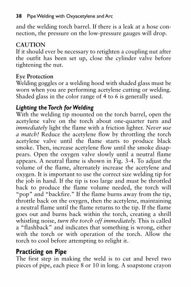
Lighting the Torch for WeldingWith the welding tip mounted on the torch barrel, open theacetylene valve on the torch about one-quarter turn andimmediately light the flame with a friction lighter. Never usea match! Reduce the acetylene flow by throttling the torchacetylene valve until the flame starts to produce blacksmoke. Then, increase acetylene flow until the smoke disap-pears. Open the oxygen valve slowly until a neutral flameappears. A neutral flame is shown in Fig. 3-4. To adjust thevolume of the flame, alternately increase the acetylene andoxygen. It is important to use the correct size welding tip forthe job in hand. If the tip is too large and must be throttledback to produce the flame volume needed, the torch will“pop” and “backfire.” If the flame burns away from the tip,throttle back on the oxygen, then the acetylene, maintaininga neutral flame until the flame returns to the tip. If the flamegoes out and burns back within the torch, creating a shrillwhistling noise, turn the torch off immediately. This is calleda “flashback” and indicates that something is wrong, eitherwith the torch or with operation of the torch. Allow thetorch to cool before attempting to relight it.
Practicing on PipeThe first step in making the weld is to cut and bevel twopieces of pipe, each piece 8 or 10 in long. A soapstone crayon

Pipe Welding with Oxyacetylene and Arc 39
can be used to mark the cut. The working pressures on theoxygen and acetylene gauges should be set as described ear-lier. Mount the cutting head on the torch barrel. The cuttingtorch (Fig. 3-5) should be ignited and adjusted for a soft neu-tral flame, using the needle valve knobs on the barrel. (A softflame is one that has a long, blue inner cone.) The needlevalve on the cutting head should be opened by turningthe knob counterclockwise. The torch should be held at anangle as shown in Fig. 3-5 in order to bevel the pipe. When
Fig. 3-4 Three basic welding flames
A NEUTRAL WELDING FLAME
AN OXIDIZING WELDING FLAME
A CARBURIZING WELDING FLAME

40 Pipe Welding with Oxyacetylene and Arc
Fig. 3-5 Correct position for making a beveled cut
the metal is red hot, depress the cutting lever (applying oxy-gen at secondary gauge pressure) and move the cutting torcharound the edge, rolling the pipe as the cut is made. Use achipping hammer (Fig. 3-6) to remove any slag at the cutedge. Lay the pieces in an angle or channel iron, as shown inFig. 3-7, leaving a 1⁄16-in gap between the pieces, and makefour tack welds 90° apart.
Making the Tack WeldsMount the welding tip on the barrel. A #3 (drill size 53) or #4(drill size 49) tip should be used for welding on 4 or 6-in pipealong with a 1⁄8-in mild steel welding rod. Light the torch andadjust it for a soft neutral flame. The flame volume will dependon the size of the tip being used. Generally, the flame should beas large as the welding tip will permit without the soft blue tipof a neutral flame pulling away from the end of the weldingtip. A tack weld is a single small weld made at the bottom ofthe beveled edges of the pieces to be welded. The tack weld ismade by playing the torch flame on both pieces, heating themetal until it is white hot, then touching the welding rod to one

Pipe Welding with Oxyacetylene and Arc 41
Fig. 3-6 A chipping hammer
TACK WELD
SUPPORTBLOCK
ANGLE IRON
Fig. 3-7 Using angle iron to align pipe for welding
side. A pool of melted metal will form and flow across to theother piece. Withdraw the torch and turn the pipe 180° andmake a tack there. Make two more tacks midway between thefirst two. There are now four tacks, 90° apart, and the pipe isready for the finish weld.

42 Pipe Welding with Oxyacetylene and Arc
WELDING ROD
DIRECTION OF WELDING
Forehand welding method.In this method, the weldingrod moves ahead of thetorch tip.
TORCH TIP
Backhand welding method.In this method, the torchmoves ahead of the weldingrod.
DIRECTION OF WELDING
Fig. 3-8 Forehand and backhand welding techniques
Forehand and Backhand TechniquesBoth the forehand and backhand techniques are shown inFig. 3-8. When the forehand method is used, the welding rodmoves ahead of the torch’s tip. When the backhand method isused, the torch moves ahead of the welding rod. In pipe weld-ing when the pipe cannot be rotated, the welder must be ableto switch easily from forehand to backhand. The forehandtechnique is used to weld from the bottom to the top of thepipe. The backhand technique is used to weld from the top to

Pipe Welding with Oxyacetylene and Arc 43
the bottom of the pipe. With either technique, the flame isdirected almost, but not quite, to the centerline of the pipe.This angle may have to be changed slightly to control themolten “puddle” in the horizontal and overhead positions.The rod must rub in the bottom of the puddle, touching eachside of the gap. As the rod is added to the puddle, the flameand rod should move in opposite directions with the flamedirected at one side and the rod touching the other side in a“whipping” or U-shaped motion. The flame must be directedat the sides of the gap just long enough to ensure that the sidemetal is melted to allow fusion and complete penetration.
Making a Rolling WeldLight the torch and set it for a neutral flame. Then, start about2� down from the top (at the 1:30 position in Fig. 3-9) and,using a U-shaped motion with the torch tip, heat the areawhite hot. When the metal starts to melt, insert the weldingrod and form a pool of molten metal. Add welding rod, keep-ing the end of the rod in the pool, and build the pool up to thetop of the pipe. As the pipe is rolled clockwise (down), the tipshould stay at the 1:30 position (Fig. 3-9), and you should use
START WELD HERE
END OF PIPE
XII
IXVI
VIII
VII
XI
X
III
IIII
V
I
II
Fig. 3-9 Starting a weld at the 1:30 position

44 Pipe Welding with Oxyacetylene and Arc
TORCH INVERTED UPTO POINT E
ANGLE BETWEEN TORCH ANDROD INCREASED AT C
90°
90°
90°G
F
E
D
BA
C
HI
90°
90°
45°
45°45°
90°
45°
22-1/2°
45°
45°45°
22-1/2°
22-1/2°22-1/2°
Fig. 3-10 Holding the torch and rod correctly for a positionweld
a whipping or U-shaped motion with the tip and welding rodat opposite sides of the U’s legs as the weld progresses.
Making a Position WeldA position weld is one that is made on a pipe that is station-ary, not rolled during the welding process. A position weld isthe most difficult weld to make, yet job conditions oftenrequire that this type of weld be made. If the technique formaking position welds is learned in the beginning, thewelder can tackle any job with confidence. In making posi-tion welds, the welder must continually change torch angleand welding rod angle as the weld progresses around thepipe. The correct angles of the rod and torch in the variouspositions are shown in Fig. 3-10.

Pipe Welding with Oxyacetylene and Arc 45
The pipe will be held stationary in a horizontal positionto make the practice weld. Tack weld a short piece, 18 or 20in long, of 1⁄2 or 5⁄8-in steel rod to one end of the pipe; thenplace the other end of the rod in a vise (Fig. 3-11).
ROD TACKED TO PIPE
Fig. 3-11 Pipe supported in a vise, ready for position weld
When you make this weld, start at the bottom (A in Fig.3-10) and weld to the top (I) on one side. Then, go back tothe bottom and weld to the top on the other side. Heat thewelding rod about 8 in above one end and make a 90° bend.Play the flame on both pieces of pipe at A (Fig. 3-10) untilthe metal melts and starts to run down into the gap. Insertthe short end of the welding rod at a 45° angle into themelted pool and build up the pool to the top of the metal.The pool will begin to run ahead of the flame, and the metalshould be white hot and melting as the pool meets it. Makethis practice weld in one pass, moving the welding rod andthe torch tip in U-shaped motions, with the end of the rodand the tip at opposite ends of the U. This is a one-pass weld

46 Pipe Welding with Oxyacetylene and Arc
with the gap filled to slightly above the top as the weldprogresses. The tip and rod angles will change, as shown inFig. 3-10 as the different positions from A to I on each sideare reached. As you learn to make position welds, you willget the feel for welding. After a practice position weld hasbeen made, the weld can be cut out, and the pipe can be usedagain for practice.
Table 3-1 shows the correct tip sizes, and oxygen andacetylene pressures for various metal thicknesses.
The orifices in the cutting head should be cleaned often,using a tip cleaner (Fig. 3-12).
Fig. 3-12 A welding tip cleaner
Safety Precautions• Never allow oxygen under pressure to come in contact
with oil, grease, dirt, or any type of organic materialthat may burn easily in high oxygen concentrations.
• Never use an acetylene torch to blow off clothing.• Never use oxygen as a substitute for compressed air
for testing purposes.• Never use acetylene at pressures in excess of 15 psig.• Always wear goggles of the correct shade when welding.

Pipe Welding with Oxyacetylene and Arc 47
• Always wear gloves when welding.• When welding or cutting on jacketed or hollow parts,
make certain that the parts are vented.• In many areas, safety rules require that another person
work alongside a welder. The other person acts as anobserver and prevents the starting of fires outside thewelder’s line of vision.
Table 3-1 Oxyacetylene Welding Tip Data
Acetylene AcetylenePressure Pressure Consumption(psig) (psig) CFH
Tip Drill MetalSize Size Min. Max. Min. Max. Min. Max. Thickness
000 75 1⁄4 2 1⁄2 2 1⁄2 3 up to 1⁄32 in
00 70 1 2 1 2 1 4 1⁄64 to 3⁄64 in
0 65 1 3 1 3 2 6 1⁄32 to 8⁄64 in
1 60 1 4 1 4 4 8 3⁄64 to 3⁄32 in
2 56 2 5 2 5 7 13 1⁄16 to 1⁄8 in
3 53 3 7 3 7 8 36 1⁄8 to 3⁄16 in
4 49 4 10 4 10 10 41 3⁄16 to 1⁄4 in
5 43 5 12 5 15 15 59 1⁄4 to 1⁄2 in
6 36 6 14 6 15 55 127 1⁄2 to 3⁄4 in
7 30 7 16 7 15 78 152 3⁄4 to 11⁄4 in
8 29 9 19 8 15 81 160 11⁄4 to 2 in
9 28 10 20 9 15 90 166 2 to 21⁄2 in
10 27 11 22 10 15 100 169 21⁄2 to 3 in
11 26 13 24 11 15 106 175 3 to 3 1⁄2 in
12 25 14 28 12 15 111 211 31⁄2 to 4 in
*Oxygen consumption is 1.1 times the acetylene under neutral flame conditions. Gasconsumption data is merely for rough estimating purposes. It will vary greatly with thematerial being welded and the particular skill of the operator. Pressures are approximatefor hose length up to 25 ft. Increase for longer hose lengths about 1 psig per 25 feet.(Courtesy Victor Equipment Co.)

48 Pipe Welding with Oxyacetylene and Arc
Shielded Metal Arc Welding (SMAW) (Also Called “Stick” Welding) This section is designed to help the experienced welderperform the most difficult pipe weld, the 6G weld. Cir-cumferential arc welding of pipe in the 6G position, pipe sta-tionary at a 45° angle, is the most difficult task a welderfaces. The American Welding Society designates weldingpositions from 1G through 6G. Most welding standardsagree that a welder who can successfully complete a pipe testin the 6G position is qualified to weld pipe in all positions.
As mentioned earlier, learning basic welding techniquesrequires hands-on training. Most welders learn to weld inapprenticeship programs, welding schools, or trade schools.Learning to make welds in all positions requires practicingcorrect procedures and techniques. The information pre-sented here is designed to help the reader advance fromlower qualification ratings to a 6G qualification.
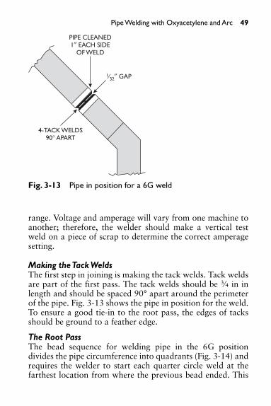
Making a Position WeldA 6G position weld must be made to join two pieces of 6-inschedule 80 black steel pipe. The joint is in a pipe axis at a45° angle, as shown in Fig. 3-13. The ends to be joined arebeveled at a 37° angle with a 3⁄32-in root opening. The wallthickness of the pipe, 0.432 in, will require seven passes. Theroot pass will be made with 3⁄32-in diameter E6010 electrodes.The hot, or second, pass is followed by two fill passes, andthe weld is finished by three cover passes, all deposited with1⁄8-in diameter E7018 electrodes.
In preparation for the weld, the pipe must be cleaned byusing a wire brush to remove scale, rust, or oil to a distance1 in back from the weld. The pipe can then be aligned in anangle or channel iron, as mentioned earlier, and tacked, leav-ing a 3⁄32-in gap for the root pass.
Setting the Welding CurrentThe weld will be made with the electrode positive and withthe welding machine set to dc (direct current) at an acceptable
Pipe Welding with Oxyacetylene and Arc 49
range. Voltage and amperage will vary from one machine toanother; therefore, the welder should make a vertical testweld on a piece of scrap to determine the correct amperagesetting.
Making the Tack WeldsThe first step in joining is making the tack welds. Tack weldsare part of the first pass. The tack welds should be 3⁄4 in inlength and should be spaced 90° apart around the perimeterof the pipe. Fig. 3-13 shows the pipe in position for the weld.To ensure a good tie-in to the root pass, the edges of tacksshould be ground to a feather edge.
The Root PassThe bead sequence for welding pipe in the 6G positiondivides the pipe circumference into quadrants (Fig. 3-14) andrequires the welder to start each quarter circle weld at thefarthest location from where the previous bead ended. This
Fig. 3-13 Pipe in position for a 6G weld
PIPE CLEANED1″ EACH SIDE
OF WELD
4-TACK WELDS90° APART
1⁄32″ GAP

50 Pipe Welding with Oxyacetylene and Arc
C
A
D
2
4th QUADRANT WELD 2nd QUADRANT WELD
1st QUADRANT WELD 3rd QUADRANT WELD
4
31
B
Fig. 3-14 Pipe divided into four quadrants
procedure ensures even heating and minimum distortion. Toensure good penetration of the root pass, the bead will berun uphill in all quadrants. Starting at A, the root pass of thefirst quadrant A to B is made. To avoid distortion of the pipe,the root pass in the second quadrant, D to C, is made next,followed by the third quadrant, A to D, and the fourth, B toC. Each quarter circle weld should start at the segment oppo-site to where the preceding weld segment ended, as seen inFig. 3-14.
The arc should be struck about 1 in in front of the pointwhere the weld is to start. A long arc should be held until theelectrode is dragged to the weld start point. At the startingpoint, the arc should be shortened to the correct length, 1⁄16
to 1⁄8 in. This method allows the welder to find the startingpoint and allows time to establish proper shielding-gas flowand arc characteristics. When welding the root pass, the cur-rent should be adjusted to maintain a keyhole (molten metalpuddle) about 11⁄2 times the electrode diameter.
If this keyhole is maintained, a good inside bead is formedwith complete penetration. As the electrode moves forward inthe joint, molten metal fills in behind the keyhole and formsthe weld. To maintain the correct keyhole size, the welderadjusts arc current and weld travel speed. If the current is set

Pipe Welding with Oxyacetylene and Arc 51
too low, the keyhole becomes too large, causing an internalundercut or melt through. The welder should watch the moltenpuddle and the ridge of solidifying metal behind the arc. Theridge should form about 3⁄8 in behind the electrode. If weldtravel is too fast, a thin, high-crowned bead will be formed.
Stepping TechniqueWhen an E6010 electrode is used for the root pass, the weldersteps the electrode in the joint using wrist action to move theelectrode forward about 11⁄2 times its diameter, then returns itto the puddle. This process is repeated along the joint. Thechange in electrode angle and technique that occurs as the weldmoves forward and upward must be gradual. Penetration willbe incomplete if the welding is done with the electrode (rod) attoo low an angle or at excessive travel speed.
Penetration can be increased by increasing the rod angleor decreasing travel speed. To maintain uniform and properroot penetration, the electrode should be held at a 90° angleto the pipe circumference when starting the weld (Fig. 3-15).As the electrode is moved forward in making the root pass,the welder will change the angle of the electrode slightly, plusor minus 5°, to maintain the “puddle” in front of or behindthe arc. The change in angle is called a “leading angle” or a“trailing angle.”
When welding above the 4 o’clock and 8 o’clock posi-tions, the electrode should not exceed a 5° trailing angle.Any time the root pass is stopped, the welder should pushthe electrode through the keyhole about 1/2 in, extinguish thearc, and withdraw the electrode. This procedure helps main-tain full root penetration at tie-ins. After welding each seg-ment, a grinder should be used to feather the ends of thebead. When the final quadrant of the root pass is completedat the top of the pass, the weld must be cleaned. A chippinghammer and a wire brush should be used to remove the slag.Using a die grinder to form the root pass into a U shape willhelp ensure that on subsequent passes the electrode willtouch bottom all the way around the joint. After grinding,

52 Pipe Welding with Oxyacetylene and Arc
8 O'CLOCK
ELECTRODE
ELECTRODE HOLDER
12
4 O'CLOCK
90°
90°
85°
90°
90°
85°
Fig. 3-15 Electrode angle changes as weld progresses
the sandy residue left by the grinder must be removed with awire brush. If this residue is not removed, it will mix with themolten metal on the next pass and contaminate the weld.
The Hot PassThe second, or “hot pass,” will require a current settingslightly higher than was used for the root pass. The hot passmust have enough current to burn out impurities in the rootpass, while at the same time not be so high as to cause theelectrode coating to break down or burn through the rootpass. A side-to-side weave motion, not exceeding three timesthe welding rod diameter, will provide full bead width.

Pipe Welding with Oxyacetylene and Arc 53
At the start of the root pass, the electrode was held at a90° angle to the weld; for the hot pass and all subsequentpasses, the electrode should be angled slightly to allow forcomplete penetration into the previous pass and to the pipewall. Slag must be removed from every pass, using a wirebrush and chipping hammer. If there is a visible flaw, theflawed area should be ground out and the residue from thegrinder removed.
The Fill PassesWhen the two fill passes are made, the first fill pass shouldbe made on the low side of the joint and the second pass onthe high side. A slight oscillating, or up-and-down, motionof the electrode allows the molten weld metal to penetrateinto both the previous pass and the side of the pipe wall.Each pass should be carefully checked for undercut and weldporosity.
The Cover PassesEach cover pass begins on the low side of the joint using theoscillating technique that was used on the fill passes. Eachquadrant is welded until the weld surrounds the pipe. After thefirst pass is cleaned, the second pass is made, penetratingequally into the first cover pass and into the fill pass below.After the second cover pass is cleaned, the third cover pass ismade. This pass should fill the remaining gap. If the entire gapcannot be filled with the third pass another pass will be needed.
When the welder grinds to remove high spots on the fin-ished weld, the abrasive should be run across the weld, notalong the weld. In an x-ray, parallel grinding marks could bemistaken for flaws in the weld.
Safety Precautions• A welder and anyone watching a welding procedure
must use a welding helmet equipped with the propershaded lens for adequate eye protection. Shaded lensesin the range of 12 to 14 are suggested.

54 Pipe Welding with Oxyacetylene and Arc
• Before operating a welding machine, check to be cer-tain that the machine is properly grounded.
• The area where welding is being done should be soenclosed that the arc is not visible outside this area.
• Heavy leather gauntlet type gloves should be wornwhile welding. Never weld while wearing wet glovesor wet shoes.
• Keep the working area clean; pick up electrode stubs,scrap metal, and so on.
• Never weld on closed containers or on containers thathave contained combustible materials.
• Welding inside tanks, boilers, or other confined spacesrequires special procedures such as using a hose maskor air-supplied hood. Oxygen depletion when workingin a confined space or vessel can have fatal results.
• Welding or cutting galvanized materials is very dan-gerous because of the fumes released by burning zinc.High-velocity fans should be so placed that the fumesare blown away from the welder and the area is wellventilated to protect other personnel in the room,building, or vicinity.
More complete information on health protection and venti-lation can be found in the American Standard Z.49.1 “Safetyin Welding and Cutting.” This document is available from:
The American Welding SocietyP.O. Box 351040Miami, FL 33135.

55
4. AUTOMATIC FIRE PROTECTION SYSTEMS
Sprinkler fitting is a very specialized branch of the pipingtrade. Sprinkler fitters serve an apprenticeship during whichthey learn the various codes and standards that apply to fireprotection installations. The tools and machinery used bysprinkler fitters are common to other branches of the pipingtrades. The scope of work involved includes installing watermains to serve sprinkler systems; installation of piping frommains to and including individual piping systems; installa-tion and servicing of valves, air compressors, and foam gen-erators; and regular maintenance, testing, and servicing ofvarious types of automatic fire protection equipment.
A sprinkler system designed for fire protection is an inte-grated system of underground and overhead piping thatincludes one or more automatically controlled water supplies.The portion of the sprinkler system located above ground is anetwork of specially sized or hydraulically designed pipinginstalled in a building, structure, or area, generally overhead,to which sprinkler heads are attached in a systematic pattern.The valve controlling each system riser is located in the riseror its supply piping. Each sprinkler riser includes a device foractuating an alarm if the system is activated.
Normally activated by heat from a fire, the system dis-charges water over the fire area through sprinkler heads. Atypical sprinkler head is shown in Fig. 4-1.
Sprinkler systems can be classified into two main types:
1. Wet-pipe systems2. Dry-pipe systems
Further variations of these systems are:
1. Preaction systems2. Deluge systems3. Combined dry-pipe and preaction systems

56 Automatic Fire Protection Systems
Wet-Pipe SystemA wet-pipe sprinkler system is fixed fire protection usingpiping filled with pressurized water and activated by fusiblesprinklers for the control of fire.
A wet-pipe sprinkler system may be installed in any struc-ture not subject to freezing temperatures. The system will auto-matically protect the structure, contents, and/or personnel fromloss or harm due to fire. However, the structure must be sub-stantial enough to support the piping system filled with water.
Operation of a Wet-Pipe SystemWhen a fire occurs, the heat produced will fuse (open) a sprin-kler head and cause water to flow. The alarm valve clapper isopened by the flow and allows pressurized water to fill theretarding chamber. The flow overcomes the retarding cham-ber’s small capacity drain and fills the alarm line. This in turncloses the pressure switch, sounds an electric alarm, and acti-vates the mechanical water motor alarm. If a water-flow indi-cator is used in the system piping, it also is activated by thewater flow. The paddle, which normally lies motionless insidethe pipe, is forced up, activating the pneumatic time-delay
Fig. 4-1 A typical sprinkler head (Courtesy of The Viking Corporation)

Automatic Fire Protection Systems 57
mechanism. This in turn energizes a microswitch, causing analarm to sound as long as water is flowing through the system.The water will flow until it is shut off manually. Componentsof a wet-pipe system are shown in Fig. 4-2.
13
8 12
11
10
1415
16
921
75
46
3
Fig. 4-2 Components of a wet-pipe sprinkler system (Courtesy ofThe Viking Corporation)
ITEM ITEM1 City Main 9 Thrust Block2 Underground Fire Main 10 Riser to Sprinkler System3 Pumper Hydrant 11 Wet Pipe Alarm Valve4 Key Valve and Road Box 12 System Piping5 Post Indicator Valve 13 Upright Sprinkler6 Main Alarm Valve Drain 14 Pendent Sprinkler7 Fire Department Connection 15 Pendent Sprinkler on Drop 8 Water Motor Alarm Nipple
16 Inspector’s Test
Dry-Pipe SystemA typical application of a dry-pipe system is in a structurethat is not heated and is subject to below-freezing tempera-tures. A dry-pipe sprinkler system is a fire protection systemthat uses water as an extinguishing agent, but differs from awet-pipe system in that the piping from the dry-pipe valve to

58 Automatic Fire Protection Systems
the fusible sprinkler heads is filled with pressurized air ornitrogen instead of water.
An air-check system is a small dry system that is directlyconnected to a wet-pipe system. The air check system uses adry valve and an air supply but does not have a separatealarm. The alarm is provided by the main alarm valve.Although the system is weighs less than the wet-pipe system,the structure housing a dry-pipe system must, nevertheless,be substantial enough to support the system piping when thesystem is filled with water.
Operation of a Dry-Pipe SystemThe components of a dry-pipe system are shown in Fig. 4-3.These components may vary somewhat due to the applica-tion of different sets of standards. The system shown inFig. 4-3 is only one possible arrangement of a dry-pipe sys-tem. Additional components of a dry-pipe system are an ade-quate supply of water taken from a city main, an elevatedstorage tank, or a ground storage reservoir with an adequatepumping system.
Underground System1. Piping. Cast iron, ductile iron, cement asbestos, and
(where permitted) PVC Schedule 40.2. Control valves, post indicator valves (PIV).3. Valve pit; usually required when multiple sprinkler
systems are serviced from a common underground sys-tem taking water supply from a city main. The pit willcontain: O.S. & Y. (open stem and yoke) valves; checkvalves or detector check, fire department connection; a21⁄2 in. � 21⁄2 in. � 4 in. hose connection; 4 in. checkvalves with ball drip (backflow preventer).
4. Auxiliary equipment. Fire hydrants with two 21⁄2 in� 21⁄2 in outlets for hose line use and a 4-in. outlet forfire pumper connection. (Outlets needed may vary,depending on the local fire department.) Structures forhousing a fire hose and equipment.

Automatic Fire Protection Systems 59
Fig. 4-3 Components of a dry-pipe sprinkler system (CourtesyThe Viking Corporation)
ITEM DESCRIPTION ITEM DESCRIPTION ITEM DESCRIPTION1 City Main 12 Dry Pipe Valve 23 Check Valve2 Pumper Type Fire Water Motor Alarm 24 Drum Drip
Hydrant 13 Cross Main 25 Drain Valve & Plug3 Underground Fire 14 Air Press Main. 26 Upright Sprinkler
Main 15 Device 27 Pendent Sprinkler4 Key Valve & Road Accelerator 28 Inspector’s Test
Box 16 (optional) 29 Valve5 Post Indicator Valve 17 Pressure Switch Inspector’s Test6 Main Drain 18 (hidden) Drain7 Ball Drip Alarm Line Strainer8 Fire Dept. 19 (hidden)9 Connection Alarm Test Valve
Water Motor Alarm 20 Drain Cup10 Drain 21 Dry Pipe Valve11 Check Valve 22 House O.S. &
Main Drain Valve Y. Valve (optional)
1
3
2
4
5
28 29
2724
23
22
19
17
20
18
16
15
25
6789
101112
13
14
26
21

60 Automatic Fire Protection Systems
Deluge SystemsA deluge system is an empty-pipe system that is used in high-hazard areas or in areas where fire may spread quickly. It canalso be used to cool surfaces such as tanks, process pipinglines, or transformers. In this type of application, open sprin-klers or spray nozzles are employed for water distribution.The deluge valve is activated by a release system employingone or more of the following methods: manual, fixed tem-perature, rate of temperature rise, radiation, smoke or com-bustion gases, hazardous vapors, or temperature increase.Once a deluge system is activated, water or other extinguish-ing agents flow through all spray nozzles and/or sprinklerheads simultaneously. Two typical applications of deluge sys-tems are flammable liquid loading facilities and aircrafthangars.
Flammable Liquid Loading FacilitiesTruck and rail loading facilities for flammable or com-bustible liquids routinely handle large volumes of potentiallydangerous materials in complete safety. Vehicles may, however,collide or hit the loading structure, rupturing tanks or pipes.Hoses, nozzles, or valves that are in constant use may breakor malfunction, and operator error is always a hazard. Anyof these failures could result in a spill, which, if ignited,could cause a disastrous fire. Because large volumes of fuelare present, it is likely that a fire would develop rapidly andendanger personnel, vehicles, cargoes, and the unprotectedloading structure. The loading site is almost always curbedor otherwise contained because it is not usually permissibleto wash the fire to another area. For that reason, the firemust be quickly extinguished and not allowed to reflash.
Control StrategyA widely used and economical way to handle the hazard is afoam-water deluge sprinkler system. The structure and theupper portion of the vehicles are kept cool by a water spray,but because water alone is not effective in the extinguishing

Automatic Fire Protection Systems 61
of buoyant burning liquids, a foaming agent must be intro-duced into the water.
Because a fire may be expected to develop very quickly,combination rate-of-rise and fixed-temperature detectors arenormally employed. Backup manual activation should alsobe provided.
Pipe lines carrying flammable liquid or fuel to the loadingarea may be equipped with shutoff valves, which are auto-matically closed when the fire detectors operate. Pumpsassociated with this system may also be interlocked to shutoff.
When the detection system operates, the deluge valveopens and supplies water to the sprinkler piping. Aqueousfilm-forming foam (AFFF) concentrate is introduced into thewater by the proportioner and is mixed in the sprinkler pip-ing. Unsealed upright sprinklers provide for the structure,the top of the vehicles, and the surrounding area. Unsealedsprinklers located on the lower structure deliver foam to theunderside of the vehicle and over the ground below. Hand-held hose lines controlled by manual valves are also fed fromthe sprinkler piping. Water flow alarms sound when the sprin-kler piping is flooded. Flammable liquid supply may bestopped by pump shutdown or by an automatic shutoffvalve actuated by a pressure switch in the sprinkler piping.The components of a fire protection system for liquid load-ing facilities are shown in Fig. 4-4.
Protein foam may be used in place of AFFF. If proteinfoam is used, special foam-water sprinklers must replacestandard open sprinklers. If large quantities of water andfoam concentrate are required, pumps that are started by asignal from the detection system are usually employed forboth liquids. Flow-control valves with downstream pressureregulators may be used in place of deluge valves to conservewater and foam concentrate.
In the event that release is in a freezing area, a pneumaticrelease system must be used and a suitable air supply pro-vided. Electrical fixed-temperature and rate-of-temperature-rise

62 Automatic Fire Protection Systems
AUXILIARY HOSE LINE
FOAMCONCENTRATE
TANK
EMERGENCY RELEASE
FUEL TRUCK
DELUGE VALVE
WATERPUMP
TO WATERSUPPLY
CONCENTRATECONTROLLER
ALARM PRESSURESWITCH TO
SHUT DOWNSYSTEM
OPEN SPRINKLERS DETECTORS
Fig. 4-4 Schematic drawing of a foam deluge system used toprotect liquid loading facilities (Courtesy of The Viking Corporation)
detection may be used in place of mechanical detection, butsuch detectors may be required to meet hazardous area stan-dards. Infrared or ultraviolet detection may also be used, butconsideration must be given to the increased potential forfalse trips.
Aircraft Hangar Fire ProtectionToday’s huge aircraft hangar represents a large and concen-trated loss potential. The primary hazard is the ignition of afuel spill involving an aircraft located in the hangar. An air-craft is extremely vulnerable to heat sources producing skintemperatures above 400°F (250°C). The hangar itself is sus-ceptible to fire damage, because usual construction includesan unprotected steel-supported roof, which will buckle andpossibly collapse when exposed to high temperatures. Aschematic drawing of an aircraft hangar fire protection sys-tem is shown in Fig. 4-5.

Automatic Fire Protection Systems 63
Control StrategyRapid control and extinguishing of fire is vital if loss is to beminimized. Even when it is not possible to save an aircraft, itis necessary to control and extinguish the fire to protect thehangar. Because buoyant flammable liquid is the principalfire hazard, extinguishing systems employing a foam-wateragent are the preferred means of protection. The aircraft andthe building structure are cooled by the water, while theburning fuel is smothered by the foam. Water alone generallymeans higher density requirements, resulting in higher costsand lower efficiency.
Three types of extinguishing systems are normally pro-vided for complete coverage, all employing foam. First, amonitor nozzle system, automatically activated by high-sen-sitivity optical detectors, is used to protect the underside ofthe aircraft. An in-floor sprinkler head and piping is shown inFig. 4-6. This sprinkler head in operation is shown in Fig. 4-7.Second, the roof sprinkler system, activated by rate-of-rise
ROOFSPRINKLERS
METERINGORIFICE
FOAMHEADER
FLOW CONTROL VALVE(FOAM CONCENTRATE)
FLOWCONTROL
VALVE(WATER)
TO STANDARDSPRINKLER SYSTEM
FOAMAGENT
RESERVOIRS
FOAM PUMPSELECTRIC-DIESEL FIRE-WATER PUMPS
ELECTRIC-DIESEL
WATER-FOAMFIRE HOSE
OSCILLATINGMONITOR
WATERSUPPLY
RESERVOIR
WATERHEADER
Fig. 4-5 Schematic drawing of an aircraft hangar fireprotection system (Courtesy of The Viking Corporation)

64 Automatic Fire Protection Systems
detectors, provides general area protection, usually by del-uge. This foam-water system provides building protection inthe event that the monitor nozzle system fails to control afire. Third, hand-held hose lines with foam nozzles are pro-vided for manual firefighting operations. Because buildingprotection is provided by a deluge system, large amounts ofwater and foam concentrate are required. These must beproperly managed to avoid exhausting the supply. Pumpingfacilities are nearly always required to meet high volumedemands.
Fig. 4-6 A Viking in-floor sprinkler head and piping underfloor grate

Automatic Fire Protection Systems 65
Operation of a Foam-Water Deluge SystemInitial detection is normally accomplished by the monitordetection system, employing either infrared or ultravioletdetectors. These systems are capable of detecting a fire in itsearly stages. However, false trips are a possibility with suchdetection systems and must be seriously considered. Manualactivation of the monitor system is also provided.
In a typical system actuation, a signal from the monitordetector is received by the release control panel (which may beinterlocked to the foam and water concentrate supply pumpstarters). This signal opens both flow control valves supplyingwater and foam to the monitor nozzles and sounds an alarm.Foam concentrate is proportioned into the water and mixed inthe supply piping. The flow-control valve operates both as adeluge valve and as a downstream pressure-regulating valve toensure the correct proportion of water and foam concentrateregardless of varying supply pressure. The monitor nozzlesmove in a programmed path to cover the aircraft, the under-aircraft areas, and areas that might contain a fuel spill. Hose
Fig. 4-7 An in-floor sprinkler head in operation

66 Automatic Fire Protection Systems
lines supplied by individual manual valves are located at con-venient places for manual firefighting.
In the event the monitor nozzles do not control the fire,the temperature will increase at the roof. This condition willtrigger a release, which is activated by either fixed-tempera-ture or rate-of-temperature-rise conditions, causing the flow-control valve to open. Unsealed, upright sprinklers thendistribute the foam over the general area. The operation ofthe roof system will trip the monitor system in the event thatit has not already functioned. That operation may also bedesigned to actuate systems in adjacent areas.
Protein or fluoroprotein foam may be used in place ofAFFF. If such foam is used, special foam-water sprinklersmust also be used in place of standard open sprinklers. In theevent that the release is in a freezing area, pneumatic opera-tion must be used and a suitable air supply must be provided.
Electrical fixed-temperature and rate-of-temperature-risedetection, utilizing a release control panel, may be used inplace of mechanical detection at the hangar roof.
Standard practice in most areas is to use Schedule 40black steel pipe and threaded black cast iron fittings formains and branch piping. 21⁄2 in I.D. (inside diameter) andlarger valves and fittings are usually flanged and joined tothreaded pipe by companion flanges.
Backflow PreventersWhen fire protection systems are connected to potable watersupplies, check valves are required in the system piping toprevent backflow of potentially polluted water into thepotable water system. When fire department pumper trucksarrive at a fire, they immediately connect a hose to the near-est fire hydrant. A hose may, if needed, be connected fromthe truck’s pump to the fire department’s Siamese connection(Figs. 4-2 and 4-3). Water is drawn from the hydrant, and ifhigher pressure is needed, the pumper truck can pump waterinto the fire protection system piping. The pumper truck iscapable of building pressure in excess of water main pressure

Automatic Fire Protection Systems 67
and, if the backflow preventer were not installed, could forcepotentially polluted water into the potable water main. Abackflow preventer is designed to prevent the reversed flowof water of nonpotable quality from being pumped orsiphoned into the potable water line.
A double-check backflow preventer is shown in Fig. 4-8.
Fig. 4-8 A double-check backflow preventer (Courtesy Watts Regulator)
Black steel pipe, grooved or threaded with grooved orthreaded fittings, is usually used for sprinkler piping. Moreinformation on grooved piping will be found in Chapter 9,“Grooved Piping Systems.”

68
5. STEAM HEATING SYSTEMS
A typical steam boiler with all essential controls and safetydevices is shown in Fig. 5-1. To be efficient in producingsteam, a boiler must be clean; oils, greases, pipe dopes, orother contaminating materials present in the boiler and pip-ing must be purged. To accomplish this, the boiler must befilled to normal water level with water to which caustic sodaor another suitable cleaning agent has been added. Theboiler must then be brought up to steaming temperature, thedrain connection opened, and the dirty water piped to a suit-able drain. Water must be added during this process toreplace the water drained out. The time needed to purge theboiler and piping depends on the boiler’s size.
All steam heating systems are one of two basic types:one-pipe or two-pipe systems. A one-pipe system uses onepipe to deliver steam to a unit and to return the condensatefrom the unit. There are variations of these two systems. Ina parallel-flow system, both steam and condensate flowin the same direction (Fig. 5-2). When the steam flows inone direction and the condensate returns against the steamflow, the system is then called a counterflow system(Fig. 5-3.) The heating unit has only one connection, andsteam enters the unit while condensate is returning throughthe same connection. The correct pitch or slope of pipingfor proper operation of a gravity flow system is essential toensure the flow of steam, air, and condensate. The correctpitch or slope for a gravity flow system is not less than 1inch in 20 feet. A one-pipe system is very dependable, andthe initial installation cost is low. Air vents are used oneach individual heating unit and at the ends of steammains.
Steam must enter the heating unit at the bottom inlet tap-ping of the unit, and because steam must enter and conden-sate return through the valve at the same time, an anglepattern valve should be used at this point. A straightway

horizontal valve would offer an obstruction to the free flowof steam and condensate. A radiator supply valve on a one-pipe system cannot be used as a throttling valve; the valvemust be either full on or full off. If the valves on this typesystem were used as throttling valves, condensate could notreturn to the boiler and noise would be created. The correctvalve for use in a one-pipe steam system is shown in Fig. 5-4.Air present in the piping of a one-pipe system must be elimi-nated in order for steam to flow. An end-of-main vent shouldbe installed near, but not at, the end of the steam main. Theright location for this vent is shown in Fig. 5-5(A). If thisvalve is not installed correctly, the float can be damaged by
Steam Heating Systems 69
COLD WATER
SAFETYVALVE
REDUCINGELBOW
BOILERWATERLEVEL
CLOSENIPPLE
DRAIN
RETURN MAIN
HOSE GATE VALVE
GATEVALVES
GLOBEVALVES
STEAM SUPPLY LINES TO SYSTEM
GATE VALVESTRAINER
CHECK VALVE
PLUGGEDTEES ANDCROSSES
GAUGE GLASS
MECHANICALFLOAT-ACTUATEDFEEDER WITHLOW-WATERCUTOFF
DRAIN VALVES
FASTEN TOBOILER BASE
NOTE: INSTALL BOILER WATERFEEDER WITH CLOSINGLEVEL 2″ MIN. BELOWNORMAL BOILER WATERLINE
4″
Fig. 5-1 A steam boiler with all essential controls

70 Steam Heating Systems
water surge. A vacuum-type air vent prevents air from enter-ing the heating unit after venting has occurred.
Air must be vented from radiators to allow steam toenter. As a result, an air vent must be installed in the venttapping on the side opposite the supply valve. There are twotypes of air vents: the open (nonvacuum) type, which has asingle nonadjustable port, and the adjustable-port vacuumvent used for proportional venting. Proportional venting is
SUPPLY VALVE
HEADER
BOILER
HARTFORD LOOP WET RETURN
WATER LINE
DRIP CONNECTIONDRY RETURN
MAIN VENT
SUPPLY MAIN
VENT VALVE
A
2″
Fig. 5-2 A one-pipe gravity parallel-flow steam system
SUPPLY VALVE
VENT VALVE
MAINVENT
MAXIMUM MAIN LENGTH 100 FEET
WATER LINE
PITCH 1 INCH IN 10 FEET
BOILER
A
Fig. 5-3 A one-pipe gravity counterflow steam system

Steam Heating Systems 71
MAIN VENT
3⁄4″ COUPLING
6″ TO 10″
DRYRETURN
AT LEAST 15″
CONNECT TOWET RETURN
MAIN VENT
STEAM MAIN
Fig. 5-4 The correct radiator valve for a one-pipe steamsystem (Courtesy Watts Regulators)
Fig. 5-5 (A) The correct location for an end-of-main vent, (B)The wrong location for an end-of-main vent
(A) (B)

72 Steam Heating Systems
best; it allows steam to enter all radiators at the same time ifthe vents are correctly adjusted. Air vents function by openingto allow steam to enter and by closing when steam or watercontacts the vent. An adjustable-port air vent is shown inFig. 5-6.
CONNECTION SIZE1⁄4″ STRAIGHT SHANK
OPERATING PRESSUREOF UP TO 11
2 PSI
MAXIMUM PRESSURE10 PSI
SIX PORTSADJUSTABLE PORT
VACUUM CHECKSEAT
FLOAT
1⁄8″ PIPETHREAD
TONGUE
Fig. 5-6 An adjustable-port air vent
Wet Returns and Dry ReturnsAt the end of the steam main, steam returns to water andbecomes condensate. This condensate is joined by the con-densate formed in various units of radiation and returns tothe boiler through the return piping. The section of pipingbetween the end of the supply main and the end-of-mainvent is called the dry return. The dry return also carriessteam and air. It is that portion of the return main which islocated above the boiler water line.
That portion of the return main that is below the boilerwater line is called a wet return, (see Fig. 5-17 later in thischapter). A wet return is also shown in Fig. 5-7; a dry return isnot shown here because the dimensions shown are used only indesigning a steam heating system. In both the wet and dryreturn systems, dimension “A” in Fig. 5-7 must be maintained.

Hartford LoopA Hartford loop (Fig. 5-2) is a pressure-balancing loop thatintroduces full boiler pressure on the return side of the boiler.Without this loop, reversed circulation could occur, allowingwater to leave the boiler via the return piping. It is the only safemethod of preventing reversed circulation. The Hartford loopmust be the full size of the return main, and the horizontal nip-ple at the return connection point should be 2 in below theboiler water line. A close nipple should be used to construct theHartford loop. If a longer nipple is used, water hammer noisewill be created. Water hammer is a wave transmitted through apipe filled or partially filled with water. The rapid passage ofsteam over the surface of the water causes a wave to form.When this wave slams against another pocket of water or thefloat of a vent valve, the hammering noise is created.
System Pressures—Designing a Steam Heating SystemA small system with a total heat loss of not more than100,000 Btu/hr (British thermal unit/hour) is sized on thebasis of 1⁄8 psig (pounds per square inch gauge) The three
Steam Heating Systems 73
STEAM SUPPLY MAIN
SAFETY FACTORFLOW
TOTALPRESSURE
DROP
BOILER WATER LINE
WET RETURNBOILER
PRESSURE DROPOF SYSTEM
STATIC HEAD"A"
Fig. 5-7 Measuring pressure drop, static head, and safetyfactors

74 Steam Heating Systems
distances for the pressure drop, the static head, and thesafety factor in Fig. 5-7 will be:
Pressure drop of system (1⁄8 psig) � 31⁄2 in of waterStatic head (friction of wet return) � 31⁄2 in of waterSafety factor (twice the static head) � 7 in of waterTotal distance � 14 in of water
It is standard practice to make distance “A” in small sys-tems not less than 18 in.
For a larger system, assume that the piping is sized for apressure drop of 1⁄2 psi. The three distances shown in Fig. 5-7would then be:
Pressure drop of system (1⁄2 psig) � 14 in of waterStatic head (friction of wet return) � 4 in of waterSafety factor (twice the static head) � 8 in of waterTotal distance � 26 in of water
It is standard practice to make minimum dimension “A”for a system based on 1⁄2-in pressure drop not less than 28 in.
To explain the previous figures:Figure 5-7 shows that water in the wet return is really in an
inverted siphon with the boiler steam pressure on top of thewater at the boiler end and steam main pressure on top ofthe water at the other end. The difference between these twopressures is the pressure drop in the system. The pressure dropis the loss due to friction of the steam passing from the boilerto the far end of the steam main. The water at the far end willrise sufficiently to overcome this difference in order to balancethe pressures, and it will rise enough, usually about 3 in, toproduce a flow through the return into the boiler.
If a one-pipe system is designed for a total pressure dropof 1⁄2 psi and a Hartford loop is used on the return, the rise inthe water level at the far end of the return, due to the differ-ence in steam pressure, will be 1⁄2 of 28 in, or 14 in. Adding3 in to this for the flow through the return main and 6 in for

a safety factor gives 23 in as the distance by which the bot-tom of the lowest part of the steam main and all heatingunits must be above the boiler water level. Higher pressuredrops would increase the distance accordingly.
More on Parallel-Flow SystemsA one-pipe parallel-flow upfeed system is designed for build-ings that have more than one floor. With this system, steamis distributed to various units of radiation through a base-ment main from which upfeed risers feed the second andthird floors. The upfeed risers are dripped back to the returnmain. The risers should be connected as shown in Fig. 5-8 tokeep the horizontal main free of condensate accumulationand to ensure the unobstructed flow of steam. A parallel-flow downfeed system has the distribution main installedabove the heating units (Fig. 5-9). With this type of system,steam and condensate flow in the same direction in thedownfeed risers. The main steam supply riser should beinstalled directly from the boiler to the overhead supplymains. The downfeed runout connections are taken from thebottom of the horizontal supply main to ensure the leastaccumulation of condensate in the main.
Steam Heating Systems 75
VENT VALVE GIVE GOODPITCH
SUPPLY VALVE
RISERAIR
VENT
RISERDRIPPED
BOILER WATER LINEDIRT POCKET
DRAIN COCK
HARTFORD RETURNCONNECTION
SUPPLY MAIN
WETRETURN
Fig. 5-8 A one-pipe parallel-flow upfeed system
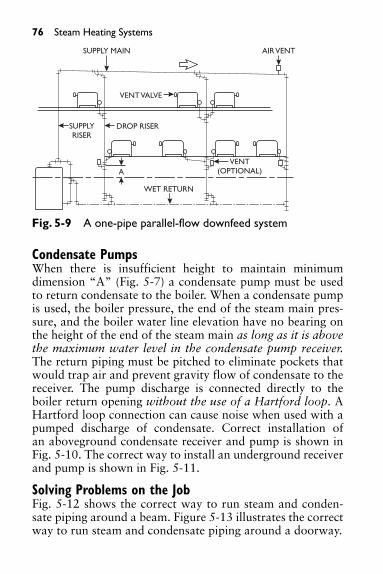
76 Steam Heating Systems
Condensate PumpsWhen there is insufficient height to maintain minimumdimension “A” (Fig. 5-7) a condensate pump must be usedto return condensate to the boiler. When a condensate pumpis used, the boiler pressure, the end of the steam main pres-sure, and the boiler water line elevation have no bearing onthe height of the end of the steam main as long as it is abovethe maximum water level in the condensate pump receiver.The return piping must be pitched to eliminate pockets thatwould trap air and prevent gravity flow of condensate to thereceiver. The pump discharge is connected directly to theboiler return opening without the use of a Hartford loop. AHartford loop connection can cause noise when used with apumped discharge of condensate. Correct installation ofan aboveground condensate receiver and pump is shown inFig. 5-10. The correct way to install an underground receiverand pump is shown in Fig. 5-11.
Solving Problems on the JobFig. 5-12 shows the correct way to run steam and conden-sate piping around a beam. Figure 5-13 illustrates the correctway to run steam and condensate piping around a doorway.
SUPPLY MAIN
VENT VALVE
DROP RISERSUPPLYRISER
WET RETURN
VENT(OPTIONAL)
AIR VENT
A
Fig. 5-9 A one-pipe parallel-flow downfeed system

Steam Heating Systems 77
STEAM SUPPLY MAIN
F&T TRAP
OPEN AIR VENT
CHECKVALVE
BOILER WATER LINE
NO PRESSURE RETURN
GATE VALVE CONDENSATE PUMP
A
SUPPLY VALVE
VENT VALVE
Fig. 5-10 A condensate receiver and pump installedaboveground
OPEN VENT ABOVEWATER LINE
WATER LINE
CHECK VALVE
GATE VALVERETURN LINE
Fig. 5-11 A condensate receiver and pump installedunderground

78 Steam Heating Systems
Fig. 5-14 demonstrates that a radiator must be level toprevent trapped condensate.
Fig. 5-15 exemplifies how the use of an eccentric reducercoupling will prevent trapping of condensate.
Fig. 5-16 explains how installing hangers to take sag outof a steam main will stop noise by allowing condensate toflow.
SAME SIZE AS STEAM MAIN
MINIMUM 2 INCH
WET RETURN MAIN SIZE
PITCH
Fig. 5-12 Correct way to pipe steam and condensate arounda beam
PLUG IN TEEFOR CLEANOUT
CONDENSATEAIR ANDCONDENSATE
DRYRETURN
PITCH
AIR LOOP
AT LEAST 1 INCH
Fig. 5-13 Correct way to pipe steam and condensate arounda doorway

Two-Pipe Heating SystemsA two-pipe heating system is a system in which the heatingunits have two connections, one for the steam supply the otherfor condensate return. The return main begins at the dischargeof a float and thermostatic trap as shown in Fig. 5-17. This trapis sized to handle the entire maximum condensate load of a sin-gle main or the connected load of individual mains. Some ofthe components used in one-pipe systems are also used in two-pipe systems. Two-pipe systems are designed to operate atpressures ranging from subatmospheric (vacuum) to high pres-sure. Condensate may be returned to the boiler by gravity flowor by the use of pumps or other mechanical return devices.
Steam Heating Systems 79
TRAPPEDCONDENSATE
LEVEL FLOOR LINE
SAGGING FLOOR
Fig. 5-14 A radiator must be level to prevent trappedcondensate
RIGHTECCENTRIC REDUCING COUPLING
WRONGREGULAR REDUCING COUPLING
WATER POCKET
Fig. 5-15 An eccentric reducer prevents trapped condensate
SAG IN STEAM SUPPLY MAIN
WATER POCKET
Fig. 5-16 Installing hangers to take sag out of piping will stopnoise

80 Steam Heating Systems
SUPPLY VALVE(B) MAIN SUPPLY
(A) HEADER
THERMOSTATIC TRAP
F&T TRAP
(C) DRYRETURN
WATERLINE
(D) WET RETURN
(E) HARTFORD LOOP
CLOSE NIPPLE
MAIN VENT
BOILER
A
2″
Fig. 5-17 The main components in a two-pipe gravity returnsystem
Thermostatic steam traps (Fig. 5-18) are the most com-monly used traps in two-pipe steam heating systems.Thermostatic traps open in response to pressure as well astemperature in order to discharge condensate and air. Whensteam reaches the thermostatic element, the trap closes toprevent the discharge of steam into the return piping.
A float and thermostatic trap (Figure 5-19) is opened bycondensate collecting in the trap and raising the float. As thefloat is raised, it opens the discharge port allowing conden-sate to enter the return piping. When air or condensate ispresent in the trap at a temperature below its designed clos-ing pressure, the thermostatic air bypass remains open. Thethermostatic air bypass closes as steam enters the trap.
Several different types of traps are used in two-pipe steamheating systems. Some include float and thermostatic traps,float traps, inverted bucket traps, and open bucket traps.
Supply valves used with a two-pipe system are globe valves,either the angle or straight type. Modulating (adjustable flow)or nonmodulating types can be used. A packless valve(Fig. 5-20) is best suited for use in two-pipe vacuum systems

Steam Heating Systems 81
Fig. 5-18 Two types of thermostatic traps
FULCRUM
OUTLET PIN BODY
AIR PASSAGE THERMOSTAT FLOAT BALL INLET
SEAT
Fig. 5-19 A float and thermostatic trap

82 Steam Heating Systems
because the construction of the valve prevents air leakage intothe system and steam leakage from the system.
HANDLE
DIAPHRAGM
LEVERS, PLUNGERS,AND STEMASSEMBLY
Fig. 5-20 A packless valve
Boiler Water LevelsIt is very important that the water level in a steam boiler bemaintained within correct limits at all times. If the waterlevel is too high, inefficient opera-tion results. If it is too low, theboiler may be permanently dam-aged or an explosion could occur.A boiler low-water cutoff or acombination boiler-water feederand low-water cutoff (Fig. 5-21) isdesigned to automatically shutdown power to a boiler in the eventof a low water condition. Try cocks(Fig. 5-22) are installed on steamboilers at the safe high water leveland at the safe low water level toprovide for manual checking of thewater level. The correct way to opena try cock is shown in Fig. 5-23.
Interesting Facts about Steam• A cubic inch of water evaporated under ordinary
atmospheric pressure (14.7 psig) will be converted into
Fig. 5-21 A waterfeeder and low-watercutoff (Courtesy ITT Industries)

Steam Heating Systems 83
Fig. 5-22 Two types of boiler try cocks
approximately one cubic foot of steam. This cubicfoot of steam exerts a mechanical force equal to lifting1955 pounds one foot high.
• The specific gravity of steam at atmospheric pressureis .462 that of air at 32°F and .0006 that of water atthe same temperature. Therefore, 28.21 cubic feet ofsteam at atmospheric pressure weighs 1 pound, and12.387 cubic feet of air weighs one pound.
• Each nominal horsepower of boilers requires from 4to 6 gallons of water per hour.
SLIGHTLYOPEN
STEAM
INCORRECTCORRECT
WIDEOPEN
TRUELEVEL
WATER
FALSELEVEL
Fig. 5-23 Correct and incorrect way of testing the waterlevel in a steam boiler

84 Steam Heating Systems
• Good boilers will evaporate from 10 to 12 pounds ofwater per pound of coal.
• One square foot of grate surface will consume from 10to 12 pounds of hard coal or from 18 to 20 pounds ofsoft coal per hour with natural draft. With forced draftsthese amounts can be doubled.
• In calculating the horsepower of boilers, allow about111⁄2 square feet of heating surface per horsepower.
• The standard unit of the horsepower of boilers (1915Power Test Code, A.S.M.E.) is: One boiler horsepoweris equivalent to the evaporation, from 212°F. feedwater, of 341⁄2 pounds of water into dry saturatedsteam at 212°.
• Steam at a given temperature is said to be saturatedwhen it is of maximum density for that temperature.Steam in contact with water is saturated steam.
• Steam that has water in the form of small drops sus-pended in it is called “wet,” or supersaturated,steam. If wet steam is heated until all the water sus-pended in it is evaporated, it is said to be “dry”steam.
• If dry saturated steam is heated when not in contactwith water, its temperature is raised and its density isdiminished or its pressure is raised. The steam is thensaid to be “superheated.”
Linear Expansion of PipingPiping carrying steam or hot water will expand or lengthenin direct relation to the temperature of the steam or hotwater. The formula for calculating the expansion distance is:
Formula:E � constant � (T � F )E � expansion in inches per hundred feet of pipe
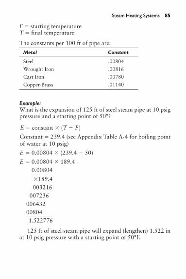
F � starting temperatureT � final temperature
The constants per 100 ft of pipe are:
Metal Constant
Steel .00804
Wrought Iron .00816
Cast Iron .00780
Copper-Brass .01140
Example:What is the expansion of 125 ft of steel steam pipe at 10 psigpressure and a starting point of 50°?
E � constant � (T � F )
Constant � 239.4 (see Appendix Table A-4 for boiling pointof water at 10 psig)
E � 0.00804 � (239.4 � 50)
E � 0.00804 � 189.40.00804
�189.4003216
007236006432008041.522776
125 ft of steel steam pipe will expand (lengthen) 1.522 inat 10 psig pressure with a starting point of 50°F.
Steam Heating Systems 85

86
6. HOT-WATER HEATING SYSTEMS
A hot-water heating system consists of a coal-, oil-, or gas-fired boiler, an expansion tank, boiler controls, piping,radiation, temperature controls, valves, air vents, and circu-lating pumps if needed. Hot-water heating systems or combi-nation heating and cooling systems are called “hydronicsystems.” Hot-water heating systems vary from simple one-pipe gravity systems to two-pipe reverse-return systems.
Boilers for hot-water heating systems are designed to oper-ate at pressures not to exceed 30 psig. Two types of boilers areused: cast-iron sectional boilers and steel tubular boilers.
Cast iron boilers are made with front and back sectionsand one or more intermediate sections. The sections areassembled on the job and are joined together by tapered nip-ples at the top and bottom. When a sectional boiler is beingassembled, extreme care must be taken to start the nipplesstraight. The sections are pulled together and held in placeby steel rods inserted through an end section, then throughintermediate sections, and through the other end section.Nuts and washers on each end of the rods must be tightenedevenly as the sections are pulled together. The cold-waterinlet is at the bottom of the rear-end section. The hot-wateroutlet is usually at the top of a center section. Tappings areprovided in the sections for the installation of controls.Modern boilers usually are equipped with a jacket installedafter the boiler is installed. Older boilers may be insulated onthe job and finished with a fabric coating.
Steel boilers are often delivered to the job site as a “pack-age” with an insulated jacket and many controls and acces-sories installed. Large steel boilers are usually delivered as abare unit, and all controls and accessories must be installedon the job. A refractory chamber must be built in the boilerfor the firing method used. After all controls and accessoriesare installed, the boiler is insulated and a jacket is installed.
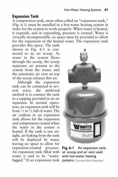
Hot-Water Heating Systems 87
Expansion TankA compression tank, more often called an “expansion tank,”(Fig. 6-1) must be installed in a hot-water heating system inorder for the system to work properly. When water is heated,it expands, and in expanding, pressure is created. Water isvirtually incompressible, so space must be provided to allowfor the expansion of the heated water. The expansion tankprovides this space. The tankshown in Fig. 6-1 is con-nected to an air scoop. Aswater in the system flowsthrough the scoop, the scoopseparates air present in thesystem from the water, andthe automatic air vent on topof the scoop releases this air.
Although the expansiontank can be connected in sev-eral ways, the preferredmethod is to connect the tankto a tapping provided in an airseparator. In normal opera-tion, an expansion tank will befrom 1⁄3 to 1⁄2 full of water. Theair cushion in an expansiontank allows for the expansionand compression created whenthe water in the system isheated. If the tank is not air-tight, air leaking from the tankwill be displaced by water,leaving no space to allow forexpansion-created pressure.An expansion tank filled withwater is said to be “water-logged.” If an expansion tank
Fig. 6-1 An expansion tank,air scoop, and air vent usedwith hot-water heatingsystems (Courtesy Watts Regulator)

88 Hot-Water Heating Systems
becomes waterlogged without an air cushion, there is noroom for expansion as the water in the system is heated.Pressure created by the expansion of the heated water willcause the relief valve to open and relieve the increased pres-sure. The expansion tank must be sized for the volume ofwater in the heating system. It is generally located in anarea above the boiler.
A combination pressure, temperature, and altitude gaugemust be installed on a hot-water boiler in order to checkoperating pressure and temperature.
Air ControlAir control is absolutely essential in operation of hydronicsystems. The air in an expansion tank should be the only airpresent in a hydronic system. But, water will absorb air, so ameans must be provided to separate air present in the waterand return it to the expansion tank. The air separatorshown in Fig. 6-2. is made to be mounted on end- or side-outlet boilers. An inline air separator is shown in Fig. 6-3.The flanged air separator shown in Fig. 6-4 is designed forlarge heating/cooling systems. The air separator shown inFig. 6-5 is made for mounting on an expansion tank. It isdesigned to restrict the flow of water from the tank withoutrestricting the flow of free air into the tank. The air separator
Fig. 6-2 Air separator for end- or side-outlet boilers (Courtesy ofBell & Gossett)

Hot-Water Heating Systems 89
Fig. 6-3 Inline air separator (scoop) (Courtesy Watts Regulator)
Fig. 6-4 An inline air separator for large systems (Courtesy of Bell & Gossett)

90 Hot-Water Heating Systems
Fig. 6-5 A tank fitting that separates air from water (Courtesy ofBell & Gossett)
shown in Fig. 6-6 is made for use in top-outlet boilers. Air isseparated in the fitting and is directed to the expansion tankthrough the side outlet of the separator.
Air in the piping system can cause noise and can alsointerfere with water circulation. When a new hot-water heat-ing system is started up, or after a system has been drained,the water entering the system will force air to the highpoints. Air must be removed from high points in piping andfrom radiation to allow water to circulate through the sys-tem. This is accomplished by use of air vents installed onpiping and radiation. Three types of air vents are shown inFig. 6-7.
Relief ValvesIf an expansion tank becomes waterlogged or if a runawayfiring condition should occur because of failure of controls,expansion and pressure could create a dangerous situation.An ASME/AGA temperature and pressure safety relief valve

Hot-Water Heating Systems 91
designed to open at 30 psi must beinstalled on every boiler. An ASME/AGAapproved relief valve for use on boilers isshown in Fig. 6-8.
System Operating ControlsSafety codes require that two aquastats beinstalled on every hot-water heatingboiler. One aquastat serves as the operat-ing control, controlling the boiler watertemperature, the other as a high-limit con-trol. The operating control (aquastat) is anormally open thermally activated electri-cal switch that closes (makes contact) ontemperature fall of the boiler water. Whenthe switch closes, the gas or oil burner isenergized, turning the burner on. Whenthe boiler water reaches the set tempera-ture, the aquastat switch opens, breakingelectrical contact, and the burner is turnedoff.
The high-limit control is a normallyclosed electrical switch that opens, break-ing electrical contact if the boiler watertemperature exceeds the set temperatureof the high-limit control. Normal prac-tice is to set the high-limit control 10°above the operating control. Operating and high-limitaquastats are shown in Fig. 6-9. Both the operating aquastatand the high-limit aquastat are wired in series with the gasor oil burner controls. If either of the aquastats “opens,”electrical contact with the gas or oil controls is broken and,providing the controls are wired correctly, the gas or oilburner will be shut off. The gas or oil controls can vary fromsimple solenoid valves to electronic and/or pneumatic con-trols, which require technicians to maintain and servicethem.
Fig. 6-6 Airseparator for top-outlet boilers(Courtesy of Bell &Gossett)

92 Hot-Water Heating Systems
Boiler operating temperatures can also be controlled bysensing devices installed outside a building. When this sys-tem is used, a rise in outside temperature will lower theboiler water temperature; a drop in outside temperature willraise the boiler water temperature.
Circulating PumpsCirculating pumps are used to force circulation of waterthrough the piping system. In one type of system, water
(A) MANUALLY OPERATEDAIR VENT
(B) MANUAL AND/ORAUTOMATIC
AIR VENT
(C) AUTOMATIC AIR VENT
Fig. 6-7 Three types of manual and automatic air vents (Courtesyof Bell & Gossett)

circulates constantly, and tempera-tures of a floor, room, or area arecontrolled by electrically or pneu-matically operated valves mountedon radiation and actuated by ther-mostats.
Temperatures in a room, floor, orarea can also be controlled by athermostat that electrically energizesa circulating pump, turning thepump on or off as temperatures riseor fall. This is called a “zoned” sys-tem; each room, floor, or area is azone with an individual run of pip-ing with its own circulating pump.
An inline circulating pump isshown in Fig. 6-10. This type pump isnormally used on small heating sys-tems. The pump shown in Fig. 6-11is designed for larger systems.Many of these type pumps are high-velocity pumps thatwill force water through the system, pushing air ahead of thewater, in some cases eliminating the need for air vents in thepiping.
Boiler Water FeedersWater is introduced into a heating system automatically by avalve of the type shown in Fig. 6-12. Given the fact that allwater contains air, air in a heating system will rise to thehighest point in the system. When a hot-water radiator doesnot get hot, it indicates that air is present in the radiator.When the air is bled off through the air vent, water enters theradiator replacing the discharged air. This causes a momen-tary drop in pressure, and water will enter the systemthrough the automatic water feeder.
Hot-water heating systems are used for many purposes.Hot-water heat is used for radiant heat in floors and ceilings.
Hot-Water Heating Systems 93
Fig. 6-8 An ASME/AGA boiler-watersafety relief valve(Courtesy Watts Regulator)

94 Hot-Water Heating Systems
190
HIGH-LIMIT AQUASTAT
180 200
180
OPERATING AQUASTAT
170 190
190
HIGH LIMIT AQUASTAT
180
200
180
OPERATING AQUASTAT
170
190
Fig. 6-9 Two aquastats must be used on hot-water boilers
Fig. 6-10 An inline circulating pump (Courtesy of Bell & Gossett)

Hot-Water Heating Systems 95
Hot-water systems using antifreeze solutions are used formelting snow and ice on sidewalks, parking garages, andother areas frequented by the public.
Whereas the water in a steam boiler must be free fromgrease or oil to allow the water to boil, oil or grease in a hot-water boiler does not affect its operating efficiency.
Hot-water heating systems where the water is heated bysteam through a heat exchanger are often used in conjunction
Fig. 6-11 A base-mounted circulating pump (Courtesy of Bell & Gossett)
Fig. 6-12 An automatic boiler water feeder (Courtesy WattsRegulator)

ThermostatsAlthough most thermostats are electric low-voltage types,schools, public buildings, and many offices use pneumatictemperature control systems with pneumatically operatedthermostats. It is apparent in every office building that thepersonal tastes of every worker vary as to the setting of ther-mostats. In public buildings, it is common practice to installtamperproof covers over thermostats. A thermostat that is
96 Hot-Water Heating Systems
with a steam heating system. A word of warning here: Thecorrect type and size of ASME/AGA-rated relief valve mustalways be installed on this type of hot-water heating system.
Balancing a Hot-Water Heating SystemA correctly sized hot-water heating system will heat everyarea in a building if the flow is evenly distributed to eachpiece of radiation. One problem often encountered is that thefirst three or four radiators on a piping run heat, while thelast two or three remain cold. The first three or four radiatorsare taking all the heat from the supply; therefore, the flowthrough these radiators must be restricted to allow hot waterto reach the remaining radiators. Balancing cocks (Fig. 6-13)installed on the return side of each radiator and adjustedcorrectly will solve this problem.
(A) FLAT-HEAD (B) SQUARE-HEAD (C) TEE-HEAD
Fig. 6-13 Three types of balancing cocks
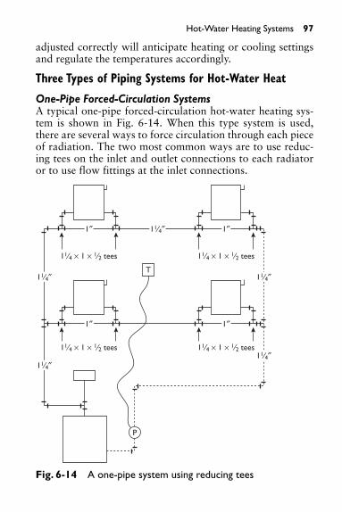
Hot-Water Heating Systems 97
adjusted correctly will anticipate heating or cooling settingsand regulate the temperatures accordingly.
Three Types of Piping Systems for Hot-Water Heat
One-Pipe Forced-Circulation SystemsA typical one-pipe forced-circulation hot-water heating sys-tem is shown in Fig. 6-14. When this type system is used,there are several ways to force circulation through each pieceof radiation. The two most common ways are to use reduc-ing tees on the inlet and outlet connections to each radiatoror to use flow fittings at the inlet connections.
11⁄4 × 1 × 1⁄2 tees 11⁄4 × 1 × 1⁄2 tees
T
P
11⁄4 × 1 × 1⁄2 tees 11⁄4 × 1 × 1⁄2 tees
1″ 1″11⁄4″
11⁄4″ 11⁄4″
11⁄4″11⁄4″
1″ 1″11⁄4″
11⁄4″ 11⁄4″
11⁄4″11⁄4″
1″ 1″1″ 1″
Fig. 6-14 A one-pipe system using reducing tees

98 Hot-Water Heating Systems
Example Using Reducing TeesAssuming the one-pipe system to be 11⁄4-in pipe, the inlet teesupplying the first radiator would be a 11⁄4 in � 1 in � 1⁄2 intee. The pipe between the inlet tee and the outlet tee from thefirst radiator would be 1 in. The outlet tee would be a 11⁄4 in� 1 in � 1⁄2 in tee. The main would continue as 11⁄4 in. Thereduction in main size between the two tees forces circula-tion through the radiator. This system is shown in Fig. 6-14.
Example Using Monoflo FittingsAgain assuming the one-pipe system to be 11⁄4-in pipe,Monoflo fittings are made to be used as either upflow ordownflow fittings. The built-in diverters in the Monoflo fit-tings serve as restrictors to force flow through the radiators.As shown in Fig. 6-15, the Monoflo fittings should be
ONE FITTING INSTALLATION–The "RING" trademark goesbetween the risers; the Returnarrow points in the directionof flow.
TWO FITTING INSTALLATION–The Monoflo Fitting is used forboth Supply and Return. The "RING"trademarks are between the risers;used in high pressure drop radiationor when radiation is below the main.
Fig. 6-15 Monoflow fitting used in hot-water heating systems(Courtesy of Bell & Gossett)
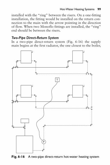
installed with the “ring” between the risers. On a one-fittinginstallation, the fitting would be installed on the return con-nection to the main with the arrow pointing in the directionof flow. When two Monoflo fittings are installed, the “ring”end should be between the risers.
Two-Pipe Direct-Return SystemIn a two-pipe direct-return system (Fig. 6-16) the supplymain begins at the first radiator, the one closest to the boiler,
Hot-Water Heating Systems 99
T
P
Fig. 6-16 A two-pipe direct-return hot-water heating system

100 Hot-Water Heating Systems
and ends at the last radiator. The return main begins at thereturn side of the first radiator and connects to the returnside of each radiator as it continues back to the return con-nection on the boiler. Each radiator in this type system has adifferent length supply and return, creating balancing prob-lems. Balancing cocks (Fig. 6-13) will be needed on thereturn from each radiator to ensure even flow to each radia-tor in the system. Two aquastats (high and low limit con-trols) maintain the boiler water temperature. A thermostatwill operate the circulating pump to maintain set thermostattemperature.
Two-Pipe Reverse-Return SystemsFig. 6-17 shows a reverse-return system, which has threezones. A zone is a floor or area served by a supply-return sys-tem where circulation of that floor or area is controlled byits own pump.
In the reverse-return system shown in Fig. 6-17, the firstradiator has the shortest supply main but has the longestreturn main. The supply main to each successive radiator isprogressively longer, but as the supply main grows longer thereturn main grows progressively shorter. The actual devel-oped length of supply and return mains to each radiator isapproximately equal; therefore the system is balanced, andeach radiator should heat evenly. In larger systems withmany radiators on each zone, balancing cocks may beneeded to ensure an even flow to each individual radiatorand to each zone. The initial cost of installing a reverse-return system is higher than for a direct return system, butthe advantages of a reverse-return system are well worth theadded cost.
Troubleshooting Steam and Hot-Water Heating SystemsTable 6-1 shows some common problems and their causes tokeep in mind when troubleshooting steam and hot-waterheating systems.

Hot-Water Heating Systems 101
T
T
P P
Fig. 6-17 A two-pipe reverse-return hot-water heating system
Water Hammer in MainsTable 6-2 shows some common problems and remedies tokeep in mind when dealing with water hammer in mains.
Water Hammer in a Hartford Loop ConnectionIn a Hartford connection a close nipple should be usedbetween the end of the return and the header drip or equaliz-ing pipe. If the nipple used at this point is too long and the

102 Hot-Water Heating Systems
Table 6-1 Troubleshooting Steam and Hot-Water Heating Systems
Problem Cause
Steam does not (a) End of main vents not working, (b) in circulate to end the wrong location, (c) the boiler is dirty; of mains. skim off grease or oil, (d) there is
insufficient water-line difference betweenthe low point of the horizontal main andthe boiler water line. In vapor systems theends of dry-return mains should be 24 inor more above the boiler water line,depending on size of installation andpressure drop. In one-pipe gravity systems,this distance should be 18 in or more.
Boiler slow to (a) May be due to poor draft, (b) boiler isrespond. too small for load, (c) inferior fuel, (d)
improper firing rate, (e) accumulation ofclinkers on grate, (f) poor draft.
Boiler smokes (a) Air leaks into boiler or breeching, through draft (b) gas outlet from firebox is plugged, door. (c) defective draft; dirty or clogged flues,
(d) reduction in breeching size.
In steam boilers, Oil, grease, dirt in boiler; clean boiler.gauge pressure builds up quickly, but steam does not circulate.
Boiler fails to (a) Poor fuel, (b) poor draft, (c) improperdeliver enough firing rate, (d) improper piping, (e) boiler heat. is too small for load, (f) heating surfaces
are covered with soot.Water line in (a) Grease, oil, dirt in boiler, (b) water
gauge glass column is connected to a very active unsteady. section and therefore is not showing
actual water level in boiler, (c) boiler isoperating at excessive output.

Water disappears (a) Oil, grease, dirt in boiler is causing from gauge glass. priming, (b) there is too great a pressure
differential between supply and returnpiping, causing water to back intoreturn, (c) valve is closed in the returnline, (d) water column is connected intoa very active boiler section or thinwaterway, (e) there are improperconnections between boilers in battery,permitting boiler with excess pressureto push water into boiler with lowerpressure, (f) firing rate is too high.
Water is carried (a) Using boiler beyond rated capacity, into steam main. (b) grease, oil, dirt in boiler,
(c) improper boiler for job, (d) outletconnections are too small, (e) firingrate is too high, (f) water level inboiler is too high.
Boiler flues (a) Poor draft, (b) combustion rate is soot up quickly. too low, (c) there is excess air in the
firebox, (d) smoky combustion, (e)improper firing rate.
Water hammer. Water hammer is caused by a shock wavetraveling through water. In steamheating systems, the wave is oftencaused by steam passing at a highvelocity over condensate collected inpiping. Steam becomes trapped inpockets of water; rapid condensationcauses these slugs of water to collidewith considerable force and becomeaudible as water hammer. Waterhammer can cause severe damage to apiping system or its components.
Hot-Water Heating Systems 103
Table 6-1 (continued)
Problem Cause

104 Hot-Water Heating Systems
Table 6-2 Water Hammer in Mains
Problem Remedy
Water pocket caused Install pipe hangers.by sagging of the main.
Improper pitch of main. Check pitch with spirit level; correct where necessary.
Pipe not sized correctly. Install correctly sized pipe.
Insufficient water line In one-pipe gravity systems, this difference between the distance should be 18 in or more; low point of the in vapor systems, the ends of dry-horizontal main and return mains should be 24 in orboiler water line. more above water line, depending
on installation and pressure drop.
Air valves for venting Install air valves in correct steam mains in one-pipe locations.gravity or vacuum systemsnot located properly.
Excessive quantities of water All boiler tappings should be usedin main due to priming and connected full size to boilerboiler or improper header header.construction.
water line of the boiler becomes too low, hammer will result.The remedy is to offset the return piping below the waterline of the boiler using a close nipple entering header drip tomaintain correct boiler water line. The top of the close nip-ple should be 2 in below the water line.
Radiator TroublesPounding noise in a one-pipe system may be caused by:
A. Radiator supply valve being partly closed or too smallB. Radiator being pitched away from supply valveC. Vent port of air valve being too large, allowing steam
to enter radiator too rapidly

If radiator does not heat, this may be caused by:
A. Air in radiator not venting.B. Drainage tongue of air valve being damaged or removed.C. Branch supply to radiator being too small.D. Vent port of air valve being clogged (one-pipe systems).E. Steam pressure higher than maximum working pres-
sure of air valve (most likely when steam is suppliedthrough a reducing valve from a high pressure supply).
F. Branch supply being improperly pitched, causing awater pocket.
G. Return branch being improperly pitched, causing a waterpocket to form and trapping air (in a vapor system).
H. In a gas- or oil-fired one-pipe vacuum system, someradiators may not heat if they were not completelyheated on a previous firing. Remedy this by changingto a nonvacuum system by using open vents on radia-tors and mains.
A radiator that cools quickly (one-pipe vacuum system)may be caused by:
A. Air leakage into system, either through leaky joints orthrough the stuffing box of the radiator supply valve ifan ordinary valve is used.
B. A malfunction of the vacuum valve, preventing forma-tion of vacuum.
C. On gas- or oil-fired system, a radiator cools quicklydue to rapid formation of the vacuum. Change to anonvacuum (open) system by changing the radiatorand main vents to a nonvacuum type.
Hot-Water Heating Systems 105

106
7. AIR CONDITIONING AND REFRIGERATION
The information in this chapter is designed with three pur-poses in mind:
• To explain the basic principles of refrigeration.• To acquaint refrigeration-servicing personnel with the
recent changes brought about by Public Law 101–549.Public Law 101–549, and its impact on the servic-ing and repairing of refrigeration and air condition-ing equipment, is a very important segment of thischapter.
• To provide servicing and troubleshooting informationfor air-conditioning and refrigeration technicians. But first, let’s deal with the basic principles of refriger-ation.
Transfer of Heat from One Substance or Element to AnotherThermodynamics is a branch of science that deals with themechanical action of heat. Refrigeration is a processdesigned to transfer heat from one medium to another. Heatalways travels from a warm body to a colder body. Heatexists at any temperature above absolute zero. Absolutezero, approximately 460°F below zero, is a theoretical termfor the lowest temperature possible, the temperature atwhich no heat exists. Heat travels in any one of three ways:
• Radiation. Radiation is the transfer of heat by waves.Heat from the sun is transferred by radiation.
• Conduction. Conduction is the transfer of heat througha medium: water or metal. One substance must touchanother for heat to be transferred in this way.
• Convection. Convection is the transfer of heat bymeans of a fluid medium, either gas or liquid, normally

Air Conditioning and Refrigeration 107
air or water. A hot-water fin tube convector transfersheat from the convector to air.
Heat transfer cannot take place without a temperaturedifference.
Measuring HeatThe British thermal unit (Btu) is the basic unit used to mea-sure heat. A Btu is the amount of heat needed to raise thetemperature of one pound of water one degree Fahrenheit.
There are several different types of refrigeration and air-conditioning equipment, but the basic principles governingair conditioning and refrigeration apply to all systems.
All refrigeration systems depend on two basic principles:
A liquid absorbs heat when it boils or evaporates to a gas.Examples:
• Freon 12 boils to vapor at –21°F at atmospheric pres-sure.
• Water boils to a gas (steam) at 212°F at atmosphericpressure.
• Liquid ammonia boils to vapor at –28°F at atmo-spheric pressure.
As vapor or gas condenses to a liquid form, heat is released.
The boiling point of a liquid is changed by changing thepressure the liquid is under. Raising the pressure raises theboiling point. Lowering the pressure lowers the boilingpoint.
Fig. 7-1 explains the changes that take place as the refrig-erant is circulated through an electrical air-conditioning sys-tem. We will assume that the thermostat has called forcooling, the compressor is operating, and the fans in the air-handling unit and the condenser are energized.
A typical electric air conditioner operates by introducinga hot liquid under high pressure into an expansion valve.

108 Air Conditioning and Refrigeration
The expansion valve releases the hot liquid, lowering thepressure and causing the hot liquid to expand into a cold liq-uid plus vapor. The cold liquid plus vapor then passesthrough the evaporator, absorbing heat from the air sur-rounding the evaporator. As the liquid plus vapor passesthrough the evaporator coil absorbing heat, it is completelyvaporized, changing from a liquid to a cold gas. The com-pressor pulls the cold gas from the evaporator or cooling coilthrough the suction line as fast as it vaporizes. Next, thecompressor compresses the cold gas to a high pressure and,in the process, raises the temperature of the cold gas, chang-ing it to a hot gas. The increased pressure forces the hot gasthrough the condenser where either air or water removes theheat from the refrigerant gas. The hot gas must be at a highertemperature than the air or water surrounding the condenserin order for heat to flow from the gas to the air or water. Asthe hot gas gives off heat in the condenser, the gas condensesand becomes a hot liquid, still under high pressure. The hotliquid enters the expansion valve, and the process begins allover again.
The reason this process works is that the hot gas leavingthe compressor is hotter than the air (or water) passing
AIR-COOLED CONDENSER
HOT LIQUID
EXPANSIONVALVE
COLD LIQUID& VAPOR
COLD AIROUT
SUCTIONLINE
COMPRESSOR
REFRIGERANT HAS ABSORBEDHEAT AND IS COMPLETELY
VAPORIZEDHOT GASUNDER HIGH
PRESSURE
Fig. 7-1 Air-conditioning system with an air-cooled condenser

Air Conditioning and Refrigeration 109
through the condenser. Thus the heat in the gas, absorbedat the evaporator, can flow to the air or water passingthrough the condenser.
The two types of refrigerating compressors used in air-conditioning equipment are reciprocating compressors andcentrifugal compressors.
Water is used as a cooling medium for a condenser inmany large air-conditioning systems. Cooled water from acooling tower basin is pumped through the water jacket ofa condenser. The cooled water absorbs heat from the hotgas in the refrigerant piping coils in the condenser. Thewater, now hot from the absorbed heat, is circulated tothe cooling tower. There it runs into a distributing troughand drips down through the baffles in the tower. As the waterdrips down, it gives off the absorbed heat. The cooled wateris now ready to be pumped back through the condenserto again absorb heat. Some water is lost through evapora-tion, so a makeup water valve is installed in the basin tomaintain the proper water level. A typical cooling tower isshown in Fig. 7-2. A piping diagram of a system using awater-cooled condenser and a cooling tower is shown inFig. 7-3.
Gauge ManifoldWhenever an air-conditioning unit must be serviced, the firstthing the technician does is to connect a set of gauges to theunit. The most important tool used by the technician is thegauge set. It is used for checking pressures, adding refriger-ant, and many other purposes. The space available will notpermit instructions for the use of this tool, nor is it necessary,because the technician for whom the balance of this chapteris written knows how to use it.
Public Law 101–549, The Clean Air ActTitle VI of the Clean Air Act Amendments of 1990,“Stratospheric Ozone Protection,” is a comprehensive programto restrict the production and use of chemicals that reduce

110 Air Conditioning and Refrigeration
COOLINGTOWER
PUMP
CONDENSER
REFRIGERANT HAS ABSORBED HEATAND IS COMPLETELY VAPORIZED
SUCTION LINE
COMPRESSOR
HOT GAS UNDER HIGH PRESSURE
EVAPORATOR
COOL AIROUT
COLD LIQUID+ VAPOR
EXPANSIONVALVE
HOTLIQUID
HOT-WATERINLET
DISTRIBUTIONBOX
AIR EXHAUSTFAN DISTRIBUTION
BOX HOT-WATERINLET
AIRINTAKE
MAKE-UPWATER VALVE
GRIDS/BAFFLESCOOLED WATERSUPPLY
TOWER BASIN
AIRINTAKE
Fig. 7-2 Cutaway view of a cooling tower
Fig. 7-3 An air-conditioning system with a cooling tower anda water-cooled condenser

Air Conditioning and Refrigeration 111
the amount of ozone in the stratosphere. Title VI replacesPart B of Title I of the Clean Air Act of 1977.
This legislation is designed to bring about changes in theway CFCs (chlorofluorocarbons) and HCFCs (hydrochloro-fluorocarbons) are handled and disposed of. The legislationwas enacted because a seasonal “hole in the sky,” a massivedrop in stratospheric ozone levels was discovered in theSouthern Hemisphere.
The Clean Air Act establishes a program that includesproduction targets and use limits and bans, recycling require-ments, venting prohibitions, labeling requirements, and safealternative measurements.
Public Law 101–549, the “Clean Air Act Amendments,”is now in effect, and it is drastically changing the way refrig-eration and air-conditioning equipment is serviced andinstalled. Installation and servicing of refrigeration and air-conditioning equipment provide employment for pipefittersspecializing in these fields. The intent of P.L. 101–549 is toprevent, so far as possible, the venting of ozone-depletingsubstances into the atmosphere. Section 608, subsection (c),paragraph 1, reads: “It is unlawful for any person in thecourse of maintaining, servicing, repairing, or disposing ofan appliance or industrial process refrigeration to know-ingly vent or otherwise knowingly release or dispose ofClass I or Class II refrigerants in a manner that permits suchsubstances to enter the environment.” The penalty forintentionally allowing the venting of ozone-depleting chem-icals, CFCs and HCFCs, can be severe. On December 2,1992, the federal Environmental Protection Agency (EPA)fined a New England contractor $18,101 for venting anHCFC refrigerant.
New refrigerant gases, such as R410A for commercialand industrial uses and 134A for automotive air condition-ers, are taking the place of ozone-depleting CFCs andHCFCs. You can search the Internet for information on newgases as they become available. Enter “refrigerant gases” inthe search box of your browser.

112 Air Conditioning and Refrigeration
Contractors (and employees) take note: If a contractorsends a technician on a service call that requires opening upa charged system and he or she does not have a certifiedrefrigerant recovery or recycling unit on the job, he and youare technically in violation of the Clean Air Act. Failure tohave the recovery or recycling unit on the job represents astrong presumption of guilt.
Three Rs are the key to understanding the purpose ofPublic Law 101–549, recover, recycle, and reclaim.
To recover refrigerant means to remove refrigerant in anycondition from an appliance without necessarily testing orreprocessing it in any way.
Since July 1, 1992, CFCs being removed from systemsmust be recovered. Recovery is not a choice; it is the law. Itis very important to record the weight of the CFC removed.This will be taken into account when the unit is chargedafter repairs are made.
To recycle refrigerant means to extract refrigerant froman appliance and clean refrigerant for reuse without meetingall the requirements for reclamation. Recycled refrigerant isrefrigerant that is cleansed using oil separation and single ormultiple passes through devices such as replaceable core fil-ter-driers, which reduce moisture, acidity, and particulatematter. Recycling is usually done at the job site.
To reclaim refrigerant means to reprocess refrigerant to atleast the purity specified in the ARI Standard 700–1988,“Specifications for Fluorocarbon Refrigerants” (Appendix Ato 40 CFR part 82, subpart F), and to verify this purity usingthe analytical methodology prescribed in the ARI Standard700–1988.
In general, reclamation involves the use of processes orprocedures available only at a reprocessing or manufactur-ing facility. Contaminated refrigerants and/or oils must berecovered and stored in containers, returned to a collectionpoint (it may be the supply house the customer deals with),and returned to the reprocessor or manufacturer.

Most CFC-based systems in use today use a mineral oillubricant. Studies have shown that there is poor miscibilitybetween many of the alternatives to CFCs and mineral oil.New oils have been developed that are more compatiblewith alternative refrigerants.
Now we come to the problem of selecting the equipmentneeded to recover and/or recycle the refrigerants. Because it iscommon practice to install refrigeration components onrooftops or other relatively inaccessible locations, both the sizeand weight of recovery and/or recycling units must be consid-ered. As the full impact of Public Law 101–549 on refrigera-tion and air-conditioning contractors is felt, the demand forrecovering and recycling units may, for a time, exceed the avail-able supply. Table 7-1 shows a listing of Class I and Class IIsubstances used in refrigeration and air-conditioning systems.
Table 7-1 Class I and Class II Substances
Sec. 602. Listing of Class I and Class II Substances
(a) List of Class I Substances—Within 60 days after enactmentof the Clean Air Act Amendments of 1990, the Administratorshall publish an initial list of Class I substances, which shallcontain the following substances:
Group Ichlorofluorocarbon-11 (CFC-11)
chlorofluorocarbon-12 (CFC-12)
chlorofluorocarbon-113 (CFC-113)
chlorofluorocarbon-114 (CFC-114)
chlorofluorocarbon-115 (CFC-115)
Group IIhalon-1211
halon-1301
halon-2402
(continued)
Air Conditioning and Refrigeration 113

114 Air Conditioning and Refrigeration
Table 7-1 (continued)
Sec. 602. Listing of Class I and Class II Substances
Group III
chlorofluorocarbon-13 (CFC-13)
chlorofluorocarbon-111 (CFC-111)
chlorofluorocarbon-112 (CFC-112)
(b) List of Class II Substances—Simultaneously with publicationof the initial list of Class I substances, the Administratorshall publish an initial list of Class II substances, which shallcontain the following substances:
hydrochlorofluorocarbon-21 (HCFC-21)
hydrochlorofluorocarbon-22 (HCFC-22)
hydrochlorofluorocarbon-31 (HCFC-31)
hydrochlorofluorocarbon-121 (HCFC-121)
hydrochlorofluorocarbon-122 (HCFC-122)
hydrochlorofluorocarbon-123 (HCFC-123)
hydrochlorofluorocarbon-124 (HCFC-124)
hydrochlorofluorocarbon-131 (HCFC-131)
hydrochlorofluorocarbon-132 (HCFC-132)
hydrochlorofluorocarbon-133 (HCFC-133)
hydrochlorofluorocarbon-141 (HCFC-141)
hydrochlorofluorocarbon-142 (HCFC-142)
hydrochlorofluorocarbon-221 (HCFC-221)
hydrochlorofluorocarbon-222 (HCFC-222)
hydrochlorofluorocarbon-223 (HCFC-223)
hydrochlorofluorocarbon-224 (HCFC-224)
hydrochlorofluorocarbon-225 (HCFC-225)
hydrochlorofluorocarbon-226 (HCFC-226)
hydrochlorofluorocarbon-231 (HCFC-231)
hydrochlorofluorocarbon-232 (HCFC-232)
hydrochlorofluorocarbon-233 (HCFC-233)

Air Conditioning and Refrigeration 115
hydrochlorofluorocarbon-234 (HCFC-234)
hydrochlorofluorocarbon-235 (HCFC-235)
hydrochlorofluorocarbon-241 (HCFC-241)
hydrochlorofluorocarbon-242 (HCFC-242)
hydrochlorofluorocarbon-243 (HCFC-243)
hydrochlorofluorocarbon-244 (HCFC-244)
hydrochlorofluorocarbon-251 (HCFC-251)
hydrochlorofluorocarbon-252 (HCFC-252)
hydrochlorofluorocarbon-253 (HCFC-253)
hydrochlorofluorocarbon-261 (HCFC-261)
hydrochlorofluorocarbon-262 (HCFC-262)
hydrochlorofluorocarbon-271 (HCFC-271)
The initial list under this subsection shall also include the isomers of the substanceslisted above. Pursuant to subsection (c), the Administrator shall add to the list of Class IIsubstances any other substance that the Administrator finds is known or mayreasonably be anticipated to cause or contribute to harmful effects on the stratosphericozone layer.
A lightweight portable recovery unit for small system ser-vices is shown in Fig. 7-4.
A typical recovery system hookup using the RS-503/13Hunit is shown in Fig. 7-5.
Used and/or contaminated refrigerant gases are sent toservice centers, which return the contaminated products tothe manufacturer for reclaiming and reuse. The refrigerantsupply houses that the contractor deals with can supplyinformation on recovery/recycling equipment and refriger-ant/oil disposal.
The scope of work for pipefitters in the air-conditioning andrefrigeration fields includes the unloading, setting, installation,and repairing of chillers, compressors, condensers, pumps,and, if used, pneumatic control systems. The installation andservicing of pneumatic control systems is another specializedbranch of the pipefitter’s trade. Various control companies

116 Air Conditioning and Refrigeration
operate schools teaching the installa-tion and servicing of pneumatic con-trol systems.
The following servicing and trou-blingshooting instructions will helpyou to diagnose problems with refrig-eration and air-conditioning systems.
Refrigerant PressuresTwelve of the most common refriger-ants are listed in Table 7-2. Eachrefrigerant is listed in a separate col-umn, and the pressures given are listedin pounds per square inch gauge (psig)or in inches of mercury if the pressuresare below zero pound gauge pressure.The refrigeration technician’s bour-don tube gauge reads 0 psig when it isnot connected to a pressure-producingsource. Pressures existing below 0 psig
are actually negative readings on the gauge and are referredto as inches of vacuum. The vacuum gauge is calibrated in
VER
Y H
IGH
PR
ESSU
RE
REF
RIG
ERA
NT
REC
OV
ERY
SYS
TEM
Fig. 7-4 Redi/Controls RefrigerantMizer Model RS-503/13H RefrigerantRecoveryUnit(Courtesy Redi/Controls Inc.)
Fig. 7-5 A typical recovery system hookup using the RS-503/13H unit (Courtesy Redi/Controls Inc.)
REFRIGERATIONSYSTEM RS-503/12-H RECOVERY UNIT
STANDARDDOT-3AAREFRIGERANTCYLINDER

Air Conditioning and Refrigeration 117
the equivalent of inches of mercury. The column at the left ofTable 7-2 shows the temperature in degrees F. The tempera-tures are given in 5° increments. The extremely low temper-atures are seldom encountered. The valves or controls can beadjusted to achieve a temperature falling between the 5°increments. In order to determine the vaporization pressurein the evaporator, the temperature of the liquid must bedetermined.
ExampleWith ammonia as the refrigerant, we want the ammonia toboil at 10° above zero F. The refrigerant plant will coolbrine. The brine, cooled to approximately 25°, will bepumped to the cooling coils. By checking the temperaturecolumn at the 10° line, then following the line to the rightunder the heading Ammonia, you can see that the pressureshould be 23.8 pounds. The head of condensing pressurescan then be checked. This is done by taking the tempera-ture of the outlet water if the refrigerating unit is watercooled. If we assume that the water is leaving the condenserat a temperature of 90°F, a reference to Table 7-2 indi-cates that the head pressure should be approximately 166pounds.
If air-cooled apparatus is encountered, the temperature ofthe air passing over the condenser must first be determined.Let us assume that the air passing over the condenser is at atemperature of 70°F. Observe in Table 7-3, that one temper-ature column gives the temperature of the liquid in the evap-orator. In our particular case, the ammonia is evaporating ata temperature of 10°F. Therefore, find this specific tempera-ture in the left-hand column and continue horizontally tothat point in the column headed 70°F. At this junction, thefigure “35” is shown. This figure, 35, is added to the air tem-perature, 70°F, giving a total of 105°F. Turn to Table 7-2 andfind the 105° line, corresponding to the temperature existingin the condenser. Table 7-2 gives the temperature at whichboiling or vaporization of each particular refrigerant takes

Tabl
e 7-
2P
ress
ure
in P
oun
ds P
er S
quar
e In
ch (
Gau
ge)
or
Inch
es o
f Vac
uum
Co
rres
pond
ing
toTe
mpe
ratu
re in
Deg
rees
F fo
r Var
ious
Co
mm
on
Ref
rige
rant
s
Tem
p.
Sulf
ur
Met
hyl
Eth
yl
Car
bon
Met
hyl
°FA
mm
onia
Dio
xide
Chl
orid
eE
than
eP
rop
ane
Chl
orid
eD
ioxi
deB
utan
eIs
obut
ane
Freo
n F-
12C
orre
ne F
orm
ate
–40
8.7
in23
.5 in
15.7
in99
.8 p
sig
1.5
psig
131.
1 ps
ig11
.0 in
–35
5.4
in22
.4 in
14.4
in10
9.8
psig
3.4
psig
156.
3 ps
ig8.
4 in
–30
1.6
in21
.1 in
11.6
in12
0.3
psig
5.6
psig
163.
1 ps
ig5.
5 in
–25
1.3
psig
19.6
in9.
2 in
132.
0 ps
ig8.
0 ps
ig17
6.3
psig
2.3
in
–20
3.6
psig
17.9
in6.
1 in
144.
8 ps
ig10
.7 p
sig
25.3
in20
5.8
psig
14.6
in0.
5 ps
ig
–15
6.2
psig
16.1
in2.
3 in
157
psig
13.6
psi
g24
.5 in
225.
8 ps
ig13
.0 in
2.4
psig
–10
9.0
psig
13.9
in0.
2 ps
ig17
2 ps
ig16
.7 p
sig
23.6
in24
7.0
psig
11.0
in4.
5 ps
ig28
.1 in
–512
.2 p
sig
11.5
in2.
0 ps
ig18
7 ps
ig20
.0 p
sig
22.6
in26
9.7
in8.
8 in
6.8
psig
27.8
in
015
.7 p
sig
8.8
in3.
8 ps
ig20
4 ps
ig23
.5 p
sig
21.5
in29
3.9
psig
15.0
in6.
3 in
9.2
psig
27.5
in26
.5 in
�5
19.6
psi
g5.
8 in
6.2
psig
221
psig
27.4
psi
g20
.3 in
319.
7 ps
ig12
.2 in
3.3
in11
.9 p
sig
27.1
in25
.9 in
�10
23.8
psi
g2.
6 in
8.6
psig
239
psig
31.4
psi
g18
.9 in
347.
1 ps
ig11
.1 in
0.2
in14
.7 p
sig
26.7
in25
.4 in
�15
28.4
psi
g0.
5 ps
ig11
.2 p
sig
257
psig
35.9
psi
g17
.4 in
376.
3 ps
ig8.
8 in
1.6
psig
17.7
psi
g26
.2 in
24.7
in
�20
33.5
psi
g2.
4 ps
ig13
.6 p
sig
275
psig
40.8
psi
g15
.8 in
407.
3 ps
ig6.
3 in
3.5
psig
21.1
psi
g25
.6 in
24.0
in
�25
39.0
psi
g4.
6 ps
ig17
.2 p
sig
292
psig
46.2
psi
g14
.0 in
440.
1 ps
ig3.
6 in
5.5
psig
24.6
psi
g24
.9 in
23.1
in
�30
45.0
psi
g7.
0 ps
ig20
.3 p
sig
320
psig
51.6
psi
g12
.2 in
474.
9 ps
ig0.
6 in
7.6
psig
28.5
psi
g24
.3 in
22.3
in
�35
51.6
psi
g9.
6 ps
ig24
.0 p
sig
343
psig
57.3
psi
g10
.1 in
511.
7 ps
ig1.
3 ps
ig9.
9 ps
ig32
.6 p
sig
23.5
in21
.1 in

�40
58.6
psi
g12
.4 p
sig
28.1
psi
g36
8 ps
ig63
.3 p
sig
8.0
in55
0.7
psig
3.0
psig
12.2
psi
g37
.0 p
sig
22.6
in20
.0 in
�45
66.3
psi
g15
.5 p
sig
32.2
psi
g39
0 ps
ig69
.9 p
sig
5.4
in59
1.8
psig
4.9
psig
14.8
psi
g41
.7 p
sig
21.7
in18
.7 in
�50
74.5
psi
g18
.8 p
sig
36.3
psi
g41
3 ps
ig77
.1 p
sig
2.3
in63
5.3
psig
6.9
psig
17.8
psi
g46
.7 p
sig
20.7
in17
.3 in
�55
83.4
psi
g22
.4 p
sig
41.7
psi
g43
8 ps
ig84
.6 p
sig
0.3
psig
681.
2 ps
ig9.
1 ps
ig20
.8 p
sig
52.0
psi
g19
.5 in
15.7
in
�60
92.9
psi
g26
.2 p
sig
46.3
psi
g46
6 ps
ig92
.4 p
sig
1.9
psig
729.
5 ps
ig11
.6 p
sig
24.0
psi
g57
.7 p
sig
18.2
in14
.0 in
�65
103.
1 ps
ig30
.4 p
sig
53.6
psi
g49
6 ps
ig10
0.7
psig
3.3
psig
780.
4 ps
ig14
.2 p
sig
27.5
psi
g63
.7 p
sig
16.7
in11
.9 in
�70
114.
1 ps
ig34
.9 p
sig
57.8
psi
g52
8 ps
ig10
9.3
psig
6.2
psig
834.
0 ps
ig16
.9 p
sig
31.1
psi
g70
.1 p
sig
15.1
in9.
8 in
�75
125.
8 ps
ig39
.8 p
sig
64.4
psi
g56
9 ps
ig11
8.5
psig
8.3
psig
890.
4 ps
ig19
.8 p
sig
35.0
psi
g76
.9 p
sig
13.4
in7.
3 in
�80
138.
3 ps
ig45
.0 p
sig
72.3
psi
g61
0 ps
ig12
8.1
psig
10.5
psi
g94
9.6
psig
22.9
psi
g39
.2 p
sig
84.1
psi
g11
.5 in
4.9
in
�85
151.
7 ps
ig50
.9 p
sig
79.4
psi
g65
7 ps
ig13
8.4
psig
12.9
psi
g10
11.3
psi
g26
.2 p
sig
43.9
psi
g91
.7 p
sig
8.4
in2.
4 in
�90
165.
9 ps
ig56
.5 p
sig
87.3
psi
g69
3 ps
ig14
9 ps
ig15
.4 p
sig
29.8
psi
g48
.6 p
sig
99.6
psi
g7.
3 in
0.5
psig
�95
181.
1 ps
ig62
.9 p
sig
95.6
psi
g16
0 ps
ig18
.2 p
sig
33.2
psi
g53
.7 p
sig
108.
1 ps
ig5.
0 in
2.1
psig
�10
019
7.2
psig
69.8
psi
g10
2.3
psig
172
psig
21.0
psi
g37
.5 p
sig
59.0
psi
g11
6.9
psig
2.4
in3.
8 ps
ig
�10
521
4.2
psig
77.1
psi
g11
3.4
psig
185
psig
24.3
psi
g41
.7 p
sig
64.6
psi
g12
6.2
psig
0.19
psi
g5.
8 ps
ig
�11
023
2.2
psig
85.1
psi
g11
8.3
psig
197
psig
27.3
psi
g46
.1 p
sig
70.4
psi
g13
6.0
psig
1.6
psig
7.7
psig
�11
525
1.5
psig
93.5
psi
g12
8.6
psig
207.
6 ps
ig31
.6 p
sig
76.7
psi
g14
6.5
psig
3.1
psig
10.4
psi
g
�12
027
1.7
psig
106.
4 ps
ig13
9.3
psig
218.
3 ps
ig35
.5 p
sig
84.3
psi
g15
7.1
psig
4.7
psig
13.1
psi
g
�12
529
3.1
psig
111.
9 ps
ig15
0.3
psig
232.
3 ps
ig39
.5 p
sig
90.1
psi
g16
8.6
psig
6.6
psig
15.7
psi
g
�13
031
5.6
psig
121.
9 ps
ig16
1.3
psig
246.
3 ps
ig44
.0 p
sig
97.3
psi
g18
0.2
psig
8.4
psig
18.2
psi
g
Not
e:in
= in
ches
of m
ercu
ry

120 Air Conditioning and Refrigeration
place; the pressure at which this occurs is listed under therefrigerant type.
If the refrigerant is ammonia at 15.7 psig, the liquid willboil at 0°F. If you desire a colder liquid, alter the pressure.This is accomplished in the refrigerating unit by adjustingthe temperature control, if a thermostat is the controller (aswith a low-side float), or by adjusting the thermostat orpressurestat in either a high-side or low-side float system.The continued operation will lower the evaporator tempera-ture and the temperature of the room in which the evaporatoris located. With an expansion valve system, if a thermostat isemployed to start and stop the system, the thermostat can beadjusted for a higher or lower temperature. Before and afterthe adjustment, the frost line on the evaporator should bechecked.
If the expansion valve is opened to admit more refriger-ant so that the pressure is raised and its boiling temperatureis increased, the suction line may frost back. Also, if theexpansion valve is closed so that less refrigerant enters theevaporator, the compressor will be unable to hold at a lowerpressure and a lower temperature. When this is done, only aportion of the coil may be effective. A coil must contain liq-uid refrigerant to be able to refrigerate. Therefore, if only apart of the coil is frosted, the other part might as well betaken out because it is doing no work. It is best to maintainthe highest pressure possible so that the compressor willwork on the densest vapor without having the suction linefrost back.
It may be desirable, however, to make a change in the suc-tion pressure to alter the temperature of the coils. If a coiltemperature at 20°F is desired with ammonia, the expansionvalve must be adjusted to maintain a constant pressure of33.5 psig in the evaporator. If a 40° temperature is desired, a58.6 psig reading on the low side would have to be main-tained. If a 40° temperature were required in the evaporatorof a methyl-chloride system, the expansion valve would haveto be adjusted to hold a constant pressure of 28.1 psig.

Air Conditioning and Refrigeration 121
Table 7-2 lists the temperature of the liquid refrigerantboiling at the constant pressure given. One factor cannot bevaried without varying the other. The only way to obtainanother boiling temperature is to adjust the expansion valveto maintain the pressure that corresponds to the temperaturedesired. If the liquid is contained in a vessel or cylinder andthe vessel is closed (such as in a supply drum), you willobserve that the pressure in such a vessel is from 1 to 5pounds greater than the temperature of the drum. This is dueto the fact that pressure has built up and prohibits furtherevaporation. If a system contains an unknown refrigerant,such as one without an odor, the kind of refrigerant may bedetermined by taking a pressure reading of the refrigerant atrest, that is, while the unit is not operating. The pressure thatcorresponds most closely to the reading will identify the par-ticular refrigerant being tested.
Table 7-2 is based on determining, from a pressure read-ing of the low side or evaporator, just what the temperatureof the boiling liquid may be. With a methyl-chloride system,if the low pressure gauge reads 2 psig, the temperature corre-sponding to this pressure is given as –5°F in Table 7-2.
With the temperature of the evaporator known (–5°F.)refer to Table 7-3. The first column in Table 7-3 on the left-hand side is the evaporator temperature. The other columnsrefer to the temperature of the water or air passing over thecondenser. Assume that the room temperature is 70°F andthat the air is passing over the condenser at this temperature.Since the evaporator temperature is known, find this temper-ature in the first column and then find the proper column forthe coolant temperature (70°F.). At the intersection underthese conditions, the figure 20 is given. This is added to theinitial temperature, thus: 20° � 70° � 90°. Take this figure(90°) and refer to Table 7-2. Run down the temperature col-umn to 90° and then across to the methyl-chloride column.You will find that a head or condensing pressure of about87.3 pounds can be expected. If the actual pressure readingvaries from this, check the condition of the apparatus.

122 Air Conditioning and Refrigeration
Table 7-3 Factors to Be Added to Initial Temperature ofCoolant to Determine Condenser Temperature
Evap.Initial Coolant Temp. °F
°F 60° 70° 80° 90° 100°
–30 15 15 15 10 10
–25 15 15 15 15 10
–20 20 20 15 15 15
–15 20 20 20 15 15
–10 20 20 20 15 15
– 5 20 20 20 15 15
0 25 25 20 20 15
�5 30 30 30 25 20
�10 35 35 30 25 20
�15 40 35 30 25 20
�20 40 35 30 25 25
�25 45 40 35 30 30
�30 50 45 40 35 35
�35 50 50 45 45 40
It is essential to obtain a pressure reading on the low orevaporator side so that the temperature of the refrigerantcan be determined. If the reading indicates too high a tem-perature, the expansion valve will have to be adjusted tomaintain the proper pressure and, of course, the properevaporating temperature. Head pressures are important;excessive pressures indicate something out of the ordinary.
Much of the equipment required for refrigeration and airconditioning is large and heavy, and many times this equipmentmust be placed on roofs or in locations where a crane mustbe used to hoist the equipment. The crane operator in mostcases cannot see beyond the edge of a roof or inside an enclo-sure, and signals must be used to guide the operator while heor she is hoisting and setting equipment. The signals shown

Air Conditioning and Refrigeration 123
in the section “Crane Signals for Mobile and OverheadCranes” of the Appendix are the standard, universally usedANSI/ASME signals for directing a crane operator.
The information on the following pages will aid you inservicing refrigeration and air-conditioning equipment.
AIR-CONDITIONING SYSTEM TROUBLE CHART
Compressor Will Not StartPossible Cause Possible Remedy
Thermostat setting Reset thermostat below roomtoo high temperature.
High head pressure Reset starter overload and determinecause of high head pressure.
Defective pressure switch Repair or replace pressure switch.
Loss of refrigerant charge Check system for leaks.
Compressor frozen Replace compressor.
Compressor Short CyclesPossible Cause Possible Remedy
Defective thermostat Replace thermostat.
Incorrect setting on low Reset low-pressure switch differential.side of pressure switch
Low refrigerant charge Check system for leaks; repair and add refrigerant.
Defective overload Replace overload.
Dirty or iced evaporator Clean or defrost evaporator.
Evaporator blower and Tighten or replace belts.motor belts slipping
Dirty or plugged filters Clean or replace air filters.

124 Air Conditioning and Refrigeration
Compressor and Condenser Fan Motor Will Not StartPossible Cause Possible Remedy
Power failure Check electrical wiring back to fuse box.
Fuse blown Replace blown or defective fuse.
Thermostat setting too high Reduce temperature setting of room thermostat.
Defective thermostat Replace or repair thermostat.
Faulty wiring Check wiring and make necessaryrepairs.
Defective controls Check and replace defective controls.
Low voltage Reset and check for cause of tripping.
Defective dual-pressure control Replace the control.
Compressor Will Not Start,but the Condenser Fan Motor RunsPossible Cause Possible Remedy
Faulty wiring to compressor Check compressor wiring and repair.
Defective compressor motor Replace the compressor.
Defective compressor overload Replace overload.(single phase only)
Defective starting capacitor Replace capacitor.(single phase only)
Condenser Fan Motor Will Not Start, but Compressor RunsPossible Cause Possible Remedy
Faulty wiring to fan motor Check fan motor wiring and repair.
Defective fan motor Replace fan motor.

Air Conditioning and Refrigeration 125
Condenser Fan Motor Runs, but the Compressor Hums andWill Not Start
Possible Cause Possible Remedy
Low voltage Check line voltage. Determine the location of the voltage drop.
Faulty wiring Check wiring and make necessary repairs.
Defective compressor Replace compressor.
High head pressure Check head pressure and complete operation of system to remove the cause of thehigh pressure condition.
Failure of one phase (three- Check fuses and wiring.phase units only)
Defective start capacitor (single Replace capacitor.phase only)
Defective potential relay (single Replace relay.phase only)
Compressor Starts, but Cycles on OverloadPossible Cause Possible Remedy
Low voltage Check line voltage. Determine the location of the voltage drop.
Faulty wiring Check wiring and make necessary repairs.
Defective running capacitor Replace capacitor.(single phase only)
Defective overload Replace overload.
Unbalanced line (three- Check wiring. Call power phase only) company.

126 Air Conditioning and Refrigeration
Evaporator Fan Motor Will Not StartPossible Cause Possible Remedy
Power failure Check electrical wiring back to fuse box.
Compressor Runs ContinuouslyPossible Cause Possible Remedy
Excessive load Check for excessive outside air infiltration and excessivesource of moisture.
Air or noncondensable gases Purge system.in the system
Dirty condenser Clean condenser.
Condenser blower and motor Tighten or replace belts.belts slipping
Thermostat setting too low Reset thermostat.
Low refrigerant charge Check system for leaks; repair and add refrigerant.
Overcharge of refrigerant Purge and remove excess refrigerant.
Compressor valves leaking Replace compressor.
Expansion valve or strainer Clean expansion valve or plugged strainer.
System Short of CapacityPossible Cause Possible Remedy
Low refrigerant charge Check system for leaks; repair and add refrigerant.
Incorrect superheat setting Adjust superheat to 10°F.of expansion valve
Defective expansion valve Repair or replace valve.
(continued)

Air Conditioning and Refrigeration 127
Possible Cause Possible Remedy
Air or noncondensable Purge system.gases in the system
Condenser blower and Tighten or replace belts.motor belts slipping
Overcharge of refrigerant Purge excess refrigerant.
Compressor valves leaking Replace compressor valves.
Expansion valve or strainer Clean valve or strainer.plugged
Condenser air short-circuiting Remove obstructions or causes of short.
Head Pressure Too HighPossible Cause Possible Remedy
Overcharge of refrigerant Purge excess refrigerant.
Air or noncondensable gases Purge system.in system
Dirty condenser Clean condenser.
Condenser blower and motor Tighten or replace belts.belts slipping
Condenser air short-circuiting Remove obstructions or causes of short-circuiting air.
Compressor and Condenser Fan Motor Will Not StartPossible Cause Possible Remedy
Power failure Check electrical wiring back to fuse box.
Fuse blown Replace blown or defective fuse.
Thermostat setting too high Reduce temperature setting of room thermostat.
Defective thermostat Replace or repair thermostat.(continued)

128 Air Conditioning and Refrigeration
Possible Cause Possible Remedy
Faulty wiring Check wiring and make necessary repairs.
Defective controls Check and replace defective controls.
Low voltage Reset and check for cause of tripping.
Defective dual-pressure control Replace the control.
Head Pressure Too LowPossible Cause Possible Remedy
Low refrigerant charge Check system for leaks; repair and add refrigerant.
Compressor valves leaking Replace compressor valves.
Suction Pressure Too HighPossible Cause Possible Remedy
Excessive load on system Remove conditions causing excessive load.
Expansion valve is stuck in Repair or replace expansion “Open” position valve.
Incorrect superheat setting of Adjust superheat setting to expansion valve 10°F.
Suction Pressure Too LowPossible Cause Possible Remedy
Low refrigerant charge Check system for leaks; repair and add refrigerant.
Expansion valve or strainer Clean expansion valve orplugged strainer.
(continued)

Air Conditioning and Refrigeration 129
Possible Cause Possible Remedy
Incorrect superheat setting of Adjust superheat setting to 10°.expansion valve
Evaporator air volume low Increase air over evaporator.
Stratification of cool air in Increase air velocity throughconditioned area grilles.
Compressor Is NoisyPossible Cause Possible Remedy
Worn or scored compressor Replace compressor.bearings
Expansion valve is stuck in Repair or replace expansion“Open” position or defective valve.
Overcharge of refrigerant or Purge system.air in system
Liquid refrigerant flooding Repair or replace expansionback to compressor valve.
Shipping or hold-down bolts Loosen compressor hold-down not loosened. bolts so compressor is freely
floating in mountings.
ServicingA malfunctioning system may be caused by one part of thesystem or a combination of several parts. For this reason, itis necessary and advisable to check the more obvious causesfirst. Each part of the system has a definite function to per-form, and if a part does not operate properly, the perfor-mance of the entire air-conditioning system will be affected.
To simplify servicing, especially with a system that isunfamiliar, the technician should remember that the refriger-ant, under proper operating conditions, travels through thesystem in one specified direction. The path of the refrigerantcan be traced through any refrigerating system. For instance,

130 Air Conditioning and Refrigeration
beginning at the receiver, the refrigerant will pass throughthe liquid shutoff valve. If this valve is partially closed, or iscompletely closed or clogged, no refrigeration is possible,even though the unit itself can and will operate.
Strainers and FiltersMost refrigerating units have a strainer or filter in the liquidline. If this device becomes clogged or filled with dirt, the liq-uid refrigerant will be unable to pass. Filters are usuallydesigned to hold a certain amount of dirt, scale, metallic par-ticles, and so on and still function, but sometimes throughcarelessness, an excessive amount of extraneous matter maybe allowed to enter the system during assembly or servicing.The remedy is obvious—the dirt and foreign matter must beremoved to permit the refrigerant to pass through the filter.
Copper TubingMany smaller air-conditioning units make use of copper tub-ing for the liquid and suction lines. Because copper is notstructurally as strong as iron or steel, it is relatively easy tocollapse the copper line with an accidental blow, thus pre-venting the circulation of the refrigerant. When this happens,a new line or section of the line must be installed.
Expansion ValvesExpansion valves must be properly adjusted and in perfectworking order to maintain the correct pressure in the lowside of the line. In many cases, oil from the compressorcrankcase enters and remains in the evaporator, occupyingthe space intended for the refrigerant. Naturally, thisreduces the refrigerating effect, and service problemsdevelop. The oil must be drained from the evaporator coil,and the compressor crankcase inspected to make sure the oillevel is correct.
CompressorsCompressors will start developing trouble after long use asthe pistons and rings, as well as the other components,

Air Conditioning and Refrigeration 131
become worn. This wear allows some of the high-pressuregas to leak at the pistons and rings, so that proper compres-sion cannot be obtained, and the compressor becomes ineffi-cient and unable to take care of the load. New rings, pistons,and connecting rods are usually all that are required to bringthe compressor back to its proper performance. Suction anddischarge valves may stick, crack, or fail entirely. Sometimes,a slight warping or piece of dirt under them results inimproper operation. Seals around the crankshaft may leakand require repacking or replacement.
CondensersThe condensers may become dirty and inefficient, resultingin high pressure, loss of efficiency, and an increase in thepower requirement.
DuctsSome air-conditioning ducts are provided with insulation onthe inside, which may tear loose and flap, resulting in noise.
Water JetsWater jets or spray heads (if used) may become clogged orworn. Automatic water valves may get out of adjustment,and the flow of water may become restricted because ofclogging of the water strainer.
Servicing ChecksThe proper diagnosis of air-conditioning system serviceproblems can only be accomplished by intelligent thought,patience, and diligence. Each and every contributory factormust be considered and eliminated before going on to someother cause. The various important steps in checking a sys-tem are listed as follows:
1. Determine the refrigerant used in the system. This is animportant factor because each refrigerant has its ownoperating characteristics, such as pressure-temperaturedifferences.

132 Air Conditioning and Refrigeration
2. Install a gauge test set. If the unit is a large one, it willhave a set of gauges as part of the equipment. Thegauge test will indicate the condition of the refrigerantby checking the pressure-temperature relations. Put athermometer on the evaporator coil, near the expan-sion valve, and obtain a reading. This temperaturereading, along with a backpressure reading, will indi-cate the refrigerant condition. Then, check forimproper expansion-coil pressure.
3. A low-pressure reading may be caused by a shortageof refrigerant, the presence of ice or water in theadjustment side of the expansion valve, moisture inthe refrigerant system, plugged screens, partly closedliquid shutoff or service valves, excessive charge, or airin the system. Improper valve settings, blocked air cir-culation over the condenser, cooling air passing overthe condenser at too high a temperature, reversedrotation of the motor, bent fan blades, or a cloggedcondenser are indicated by high head pressures.
4. Frost or a sweat line on the coil should be noted. A coilis only active up to its frost or sweat line. All lengths oftubing beyond the frost or sweat line are inactive, sincethey do not receive liquid refrigerant. For greatest effi-ciency, the entire coil must have frost or sweat, and ifthe liquid line is obstructed, the screen plugged, or theexpansion improperly set, the proper amount of liquidrefrigerant will not enter the evaporator, and only alimited portion of the coil will frost or sweat, depend-ing on the type of liquid refrigerant used.
5. An increase or overabundance of refrigerant will causethe entire coil, and possibly the suction line, to frost orsweat. This may also be caused by a leaky needle,improper adjustment, ice in the adjustment side of theexpansion valve, or fused thermostat contacts. Mostcomplaints with regard to excessive or insufficientfrosting are due to weather conditions.

Air Conditioning and Refrigeration 133
6. Improper operation will occur if refrigerant hasescaped from the system. The first thing to do whenleakage has occurred is to detect and repair the leak.Indications of refrigerant shortage include hissing atthe expansion valve, a warm or hot liquid line, little orno frost on the expansion valve or coil, continuousoperation, low head pressure, and bubbles in the sightglass if it is inserted into the liquid line and used to testfor refrigerant shortage.
7. Bubbles may form in the sight glass if the head pres-sure is under 120 pounds with F-12 and under 100pounds with methyl chloride. An excellent indicationof leakage is the presence of oil on a joint or fitting;methyl-chloride and F-12 dissolve oils, and when aleak occurs, the escaped refrigerant evaporates in theatmosphere, leaving the oil behind. Refrigerant mustbe added to system that has a refrigerant shortageuntil the bubbles in the sight glass cease, or until thehissing sound at the expansion valve is eliminated.
8. Check for improper installation. Compressor unitsand low sides must be level. Tubes and fittings formingthe liquid and suction lines must be the proper size.Baffles, ducts, and eliminators must be properlylocated and not obstructed. Ducts must be insulatedproperly, or short-circuiting of air currents may takeplace, causing the ducts to sweat. Liquid and suctionlines must be checked for pinches, sharp or flattenedbends, and obstructions. Lines should not be runalong the ceiling in a hot room, and the lines shouldnot run adjacent to any active hot-water or steampipes.
9. The location and installation of the thermostat mustbe checked. The thermostatic-switch bulb should beinstalled in a location where average temperatureconditions exist. The thermostatic bulb, or switchitself (if self-contained), should not be placed where

134 Air Conditioning and Refrigeration
an inrush of warm air, such as that caused by theopening of doors or windows, will cause the mecha-nism to cut in prematurely. Use thermostatic controlswitches with a minimum of tubing—gas will con-dense in long runs of tubing and the condensate willproduce erratic operation. If a thermostatic bulb isused to control a liquid bath or brine, the bulb shouldbe housed in a dry well or cavity, which should belocated where average temperature conditions will bestable.
10. The condition of the thermostatic bulb should bechecked. Apply heat gently by means of a cloth satu-rated with hot water or else hold the bulb in yourhand. If the contacts do not close after applying heat,the thermostatic element is discharged. Dirty or oxi-dized contacts can also cause defective operation.
11. Starter fuses should be checked and, if blown, replacedwith fuses of the proper size. Determine the cause ofthe trouble—shortage of oil, air in the system, over-charge, misalignment, high backpressure, lack of airor water over the condenser or motor—any of whichmay cause the fuses to blow. If the trouble is not cor-rected, serious damage can result in a relatively shorttime.
. 12. Filters and/or screens must be checked. A cloggedscreen or filter, or a pinched or clogged liquid line,will produce the same trouble as a leaky or stuckexpansion valve, depending on the degree of theobstruction.
13. A leaky or stuck expansion-valve needle will be indi-cated by a low pressure in the evaporator side andcontinuous operation of the unit. Sometimes a low-pressure control is wired in series with the thermo-static control and motor. When this is done, thelow-pressure control will cut out, and the unit willremain inoperative.

Air Conditioning and Refrigeration 135
Common Troubles in Automatic Expansion ValveSystems with Thermostatic Control
Refrigerant Shortage
• Warm or hot liquid line.• Hissing sound at expansion valve.• Low head or condensing pressure.• Evaporator not entirely chilled.• Poor refrigeration.• Low-side pressure may be high if only gas is entering
the evaporator.
Poor Refrigeration
• Heavy coat of frost or ice on evaporator• Refrigerant shortage• Thermostat not adjusted properly• Thermostat defective• Thermostat shifted and not level• Thermostat shielded by covering• Thermostat in a draft• Stuck expansion valve• Expansion valve set too low; allows only a portion of
the evaporator to be effective• Liquid line pinched or restricted• Suction line pinched or restricted• Compressor valves defective, broken, or sticking• Strainer on liquid or suction line clogged• Partially closed liquid- or suction-line valves• Ice or moisture in adjustment side of expansion valve

136 Air Conditioning and Refrigeration
• Ice freezing in seat of expansion valve• High head pressure• Compressor losing efficiency through wear• Compressor may be too small
Compressor Discharge Valve Defective
• Low head pressure.• Poor refrigeration.• Compressor excessively warm.• If the compressor is stopped, pressure will equalize.
Expansion-Valve Needle Stuck Open
• Poor refrigeration.• High head pressure if stuck partially open.• Low head pressure and high backpressure if stuck
fully open.• Frosted or sweating suction line.• Hissing sound at expansion valve.• Impossible to adjust for higher or lower backpressures.• On methyl-chloride and F-12 units, this may be caused
by moisture freezing at seat of expansion valve.• Improper oil, freezing at seat.• Improper oil and high compressor temperatures may
result in carbonization, which may build up at theexpansion valve, especially if filters are defective.
Expansion Valve Needle Stuck Closed
• No refrigeration if shut tight.• Little refrigeration if stuck partially shut.

Air Conditioning and Refrigeration 137
• Evaporator will be pumped down so that the low sidewill show an unduly low pressure.
• A pinched liquid line, plugged filter, or closed handvalve will give the same symptoms.
• On methyl-chloride and F-12 units, this may be causedby moisture freezing in the expansion valves.
High Head Pressure
• Air in system.• Excessive refrigerant charge.• Air or water going through condenser at too high a
temperature.• If the unit is an air-cooled type, air circulation over
condenser blocked.• If the unit is of the water-cooled type, the water may
be turned off or restricted.• Rotation of motor reversed.• If a higher setting is used on the expansion valve, the
head pressure will be higher, and vice versa.
Unable to Adjust Valve
• Refrigeration shortage• Compressor valve broken or defective• Partially plugged screens or filters• Liquid line pinched almost closed• Stoppage in fitting or restriction in liquid line• Needle or seat eroded and leaky• Oil-logged coil• Ice in adjustment side of expansion valve
138 Air Conditioning and Refrigeration
Low Head Pressure
• Refrigerant shortage• Worn pistons• Head or clearance gasket too thick• Suction valve worn, split, or stuck• Low setting on expansion valve• Gasket between cylinders blown
Suction Line and Drier Coil Frosted or Sweating
• Expansion valve stuck open or leaky• Needle seat eroded or corroded• Valve set at too high a backpressure• Ice or moisture in adjustment side of expansion valve• Thermostat out of order or poorly located• Fan not operating, so that air is not blown over coils• No water, or water pump not operating to pass water
over evaporator
Common Troubles in Thermostatic Expansion-ValveSystems with Low-Side or Thermostatic Control
Refrigerant Shortage
• Continuous operation• Low head pressure• Poor refrigeration• Warm or hot liquid line• Evaporator coils not chilled throughout entire length• Hissing at expansion line

Air Conditioning and Refrigeration 139
Poor Refrigeration
• Heavy coating of ice or frost on evaporator coils• Expansion valve set too high• Refrigerant shortage• Thermostat bulb placed where there is little change in
coil temperature• Thermostat bulb placed where it is in a cold pocket
and not affected by average conditions• Expansion valve set too low• Pigtail of expansion valve improperly placed, so that
maximum coil surface is not used• Compressor valves defective, broken, or sticking• Liquid line pinched• Suction line pinched• Strainer clogged• Suction line too small for job• Partially closed liquid- or suction-line hand valves• Compressor too small for job• Moisture in methyl-chloride or F-12 refrigerant
Compressor Discharge Valve Defective
• Low head pressure.• Poor refrigeration.• When the compressor is stopped, pressures equalize.
Expansion Valve Needle Stuck Open
• Continuous operation• Poor refrigeration

140 Air Conditioning and Refrigeration
• High head pressure• Hissing sound at expansion valve• Moisture in methyl-chloride or F-12 refrigerant
Low Head Pressure
• Shortage of refrigerant• Worn pistons in compressor• Warped, split, or stuck discharge valve• Suction valve warped, split, or stuck• Expansion-valve needle stuck wide open• Gasket between cylinder blown• Thermostatic bulb discharged
Suction Line and Drier Coil Sweating or Frosted
• Expansion-valve needle stuck open• Expansion-valve needle or seat eroded and leaky• Expansion valve set too high above cutout point• Control-switch points fused together• Low-side control switch locked in operating position
Expansion Valve Needle Stuck Partially Closed
• Little or no refrigeration.• The high-pressure safety cutout may trip.• Evaporator will be pumped down and show a low
pressure at below cutin temperature.
• If the liquid line is plugged, the thermostatic bulb dis-charged, or the capillary tube pinched, the result willbe the same as a needle stuck shut.
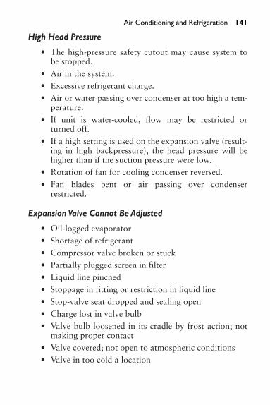
High Head Pressure
• The high-pressure safety cutout may cause system tobe stopped.
• Air in the system.• Excessive refrigerant charge.• Air or water passing over condenser at too high a tem-
perature.• If unit is water-cooled, flow may be restricted or
turned off.• If a high setting is used on the expansion valve (result-
ing in high backpressure), the head pressure will behigher than if the suction pressure were low.
• Rotation of fan for cooling condenser reversed.• Fan blades bent or air passing over condenser
restricted.
Expansion Valve Cannot Be Adjusted
• Oil-logged evaporator• Shortage of refrigerant• Compressor valve broken or stuck• Partially plugged screen in filter• Liquid line pinched• Stoppage in fitting or restriction in liquid line• Stop-valve seat dropped and sealing open• Charge lost in valve bulb• Valve bulb loosened in its cradle by frost action; not
making proper contact• Valve covered; not open to atmospheric conditions• Valve in too cold a location
Air Conditioning and Refrigeration 141
8. PROCESS PIPING USING PLASTICS
This chapter is intended to serve as a reference for those seek-ing information on various kinds of plastic pipe. And forthose who do not know that plastic pipe can be welded, itmay come as a surprise. The information is presented to walkthe reader through the various steps of hot-gas welding.
Process piping makes up a large part of pipefitters’ andwelders’ work. Process piping can be generally defined aspiping carrying substances, liquid or solid, used in manufac-turing or processing of other materials or substances.
Types of Piping
PVC (Polyvinyl Chloride) Conforming to ASTM D-1784,Class 12454-B Formerly Designated as Type I, Grade IPVC is the most frequently specified of all thermoplasticmaterials. It is used for chemical processing, industrial plat-ing, chilled-water distribution, deionized water lines, chemi-cal drainage, and irrigation systems. PVC has high-qualityphysical properties and resistance to corrosion and chemicalattack by acids, alkalis, salt solutions, and many other chem-icals. It is attacked, however, by polar solvents such asketones, some chlorinated hydrocarbons, and aromatics.The maximum service temperature of PVC is 140�F. It has adesign stress of 2,000 psig and the highest long-term hydro-static strength at 73�F of any of the major thermoplasticsused for piping systems. PVC is joined by solvent cementing,threading, or flanging. The method used depends on theschedule pipe used, 40 or 80.
CPVC (Chlorinated Polyvinyl Chloride) Conforming toASTM D-1784, Class 23447-B, Formerly Designated as Type IV, Grade 1CPVC has physical properties at 73�F similar to those ofPVC, and its chemical resistance is similar to that of PVC.
142

CPVC, with a design stress of 2000 psig and a maximum ser-vice temperature of 210�F, has proven to be an excellentmaterial for hot corrosive liquids, hot and cold water distri-bution, and similar applications above the temperaturerange of PVC. Like PVC, CPVC is joined by solvent cement-ing, threading, or flanging.
Solvent Cementing of PVC and CPVC Pipe and FittingsPVC and CPVC pipe and fittings are made with a high-glosshard finish. A primer must be used when solvent cementingif a good joint is to be made. Primer penetrates and softensthe hard surfaces of both the pipe and fittings. Follow theinstructions furnished with the primer. After the primer hassoftened the pipe and fitting surfaces, apply the PVC and/orCPVC cement.
(PP) Polypropylene Homopolymer, Conforming to ASTM D4101, Class PP110-B67154, Formerly Designated as Type IPP is a member of the polyolefin family of plastics. PP has lessphysical strength than PVC, but it is chemically resistant toorganic solvents as well as acids and alkalis. Polypropyleneshould not be used in contact with strong oxidizing acids,chlorinated hydrocarbons, and aromatics. PP is useful forsalt-water disposal lines, crude oil piping, and low-pressuregas-gathering systems. PP is an excellent material for labora-tory and industrial drainage when mixtures of acids, bases,and solvents are involved. Polypropylene is joined by thethermo-seal fusion process, threading, or flanging.
PVDF (Kynar) Polyvinylidene FluoridePVDF is a high-molecular-weight fluorocarbon that hassuperior abrasion resistance, chemical resistance, dielectricproperties, and mechanical strength. PVDF maintains thesecharacteristics over a temperature range of �40 to 250�F.PVDF is highly resistant to wet or dry chlorine, bromineand other halogens, most strong acids and bases, aliphat-ics, aromatics, alcohols, and chlorinated solvents. PVDF is
Process Piping Using Plastics 143

144 Process Piping Using Plastics
not recommended for use with ketones or esters. PVDF isjoined by the thermo-seal fusion process, threading, orflanging.
Pipe Preparation
CuttingPlastic pipe can be cut easily using a power saw or handsaw,circular saw, or band saw. When a handsaw is used, it mustbe used with a miter box to ensure square cuts. Tubing cut-ters are designed for quick, clean cuts through plastic pipe.When tubing cutters are used, the cutters should have cut-ting wheels especially designed for cutting plastic pipe. Thecutter shown in Fig. 8-1 has a quick-acting slide mechanismand is made in five sizes to cut plastic pipe from 1⁄8 through6 in O.D. (outside diameter). The cutter shown in Fig. 8-2has a compound ratchet lever mechanism and will cut pipefrom 1⁄8 through 23⁄8 in O.D.
Fig. 8-1 A quick-acting plastic-pipe cutter (Courtesy Ridge Tool Co.)
Deburring and BevelingAll burrs, chips, filings, and so on should be removed fromboth the pipe I.D. (inside diameter) and O.D. Use a knife,

half-round file, or a deburring tool (Fig. 8-3) to remove allburrs. Pipe should be beveled to approximately the angleshown in Fig. 8-4.
Polypropylene Piping and Fittings
Pipe JoiningPolypropylene is joined by a process called thermal bonding,which applies to all NIBCO/Chemtrol polypropylene andKynar pressure piping systems, including molded socket fit-tings and socket-type valve connections. This process involvesthe application of regulated heat uniformly and simultaneouslyto pipe and fitting mating surfaces so that controlled melting,the thermo-seal process, occurs at these surfaces. Due to spacelimitations, the thermo-seal process is not explained here, butcan be found at the NIBCO/Chemtrol Web site.
Repairing Thermoplastic Pipe JointsBecause we talk about welding in this book, it is appro-priate to explain that there are times when welding must be
Process Piping Using Plastics 145
Fig. 8-2 A compound-lever plastic-pipe cutter (Courtesy RidgeTool Co.)

146 Process Piping Using Plastics
performed on thermoplastic pipe. If a faulty or leaking jointis found, the most common method for repairing faulty andleaking joints is hot-gas welding at the fillet formed by thejunction of the fitting socket entrance and the pipe. Hot-gaswelding (which is similar to gas welding with metals, exceptthat hot gas is used for melting instead of a direct flame), con-sists of simultaneously melting the surface of a plastic filler
Fig. 8-3 Deburring tools (Courtesy Ridge Tool Co.)
1⁄16 TO 3⁄ 32 in
10—15°
Fig. 8-4 Pipe beveled to correct angle

rod and the surfaces of the base material in the fillet area,while forcing the softened rod into the softened fillet.
Welding with plastics involves only surface meltingbecause plastics, unlike metals, must never be puddled. Theresulting weld is not as strong as the parent pipe and fittingmaterial; therefore, fillet welding is recommended for minorleaks only.
Pipe and fittings must always be the same type; dissimi-lar pipe and fittings must never be joined. Polypropylenepipe and fittings must never be joined to Kynar pipe and fit-tings.
Welding Tools and Materials
Tools
• A hot-gas welding torch (Fig. 8-5) with a 400 to 550-W (watt) heating element and pressure regulatorequipped with pressure gauge
• Cutting pliers• Hand grinder (optional)• Nitrogen or other inert gas (polypropylene or Kynar
only)• Source of compressed air• Filler rod• Emery cloth• Cotton rags
Weld Area PreparationWipe all dirt, oil, and moisture from the joint area. A mildsolvent may be needed to remove oils.
CAUTIONMake sure that all liquid has been removed from the portionof the piping system where the weld is to be made.
Process Piping Using Plastics 147

148 Process Piping Using Plastics
OU
TER
BA
RR
EL
HO
T A
IR
TH
REA
DED
NO
ZZ
LE
WEL
DIN
G T
IP O
R T
OO
L
PREH
EAT
FO
R B
ASE
MAT
ERIA
L
PREH
EAT
FO
R B
ASE
MAT
ERIA
L
DIR
ECT
ION
120
VOLT
S A
C
CO
MPR
ESSE
D A
IR O
R IN
ERT
GA
S
AIR
HO
SE
AIR
-CO
OLE
D H
AR
DIC
CO
LD A
IR
SPA
NN
ER N
UT
STA
INLE
SS-S
TEE
L H
EAT
ING
ELE
MEN
T
HEA
TIN
G C
HA
MBE
R
WEL
DIN
G R
OD
Fig
.8-5
A h
ot-g
as w
eldi
ng t
orch
(Cou
rtes
y KA
MW
ELD
Pro
duct
s Co
.Inc
.)

Welding Faulty Joints
1. Remove residual solvent cement from the weld areausing emery cloth (Fig. 8-6). When welding threadedjoints, a file can be used to remove threads in the weldarea.
2. Wipe the weld area free of dust, dirt, and moisture,using a cotton rag.
3. Determine the amount of the correct filler rod neededto make one complete pass around the joint by wrap-ping the rod around the pipe to be welded, as shownin Fig. 8-7. Increase this length enough to allow forhandling the rod at the end of the pass.
Process Piping Using Plastics 149
Fig. 8-6 Remove residual solvent cement from the weld areausing an emery cloth (Courtesy of CHEMTROL ® a brand of NIBCO ®)
Image rights not available.

150 Process Piping Using Plastics
4. Make about a 60� angularcut on the lead end of thefiller rod (Fig. 8-8). Thiswill make it easier to initiatemelting and will ensure thefusion of the rod and basematerial at the beginning ofthe weld.
5. Welding temperatures varyfor different thermoplasticmaterials (500 to 550�F forPVC and CPVC, 550 to
Fig. 8-7 Determine the amount of correct filler rod needed(Courtesy of CHEMTROL ® a brand of NIBCO ®)
Fig. 8-8 Make a 60� cut onthe filler rod (Courtesy ofCHEMTROL ® a brand of NIBCO)
Image rightsnot available.
Image rights not available.

600�F for PP, 575 to 600�F for Kynar). Welding tem-peratures can be adjusted for the various thermoplas-tic materials as well as any for desired welding rate byadjusting the pressure regulator (which controls thegas flow) between 3 and 8 psig.
6. With air or an inert gas flowing through the weldingtorch, insert the electrical plug for the heating elementinto an appropriate electrical socket to facilitate theheating of the gas, and wait approximately 7 minutesfor the welding gas to reach the proper temperature.
CAUTIONThe metal barrel of the heating torch houses the heating ele-ment. It can attain extremely high temperatures. Avoid con-tact with the barrel, and do not allow it to contact anycombustible materials.
7. Place the leading end of the filler rod into the filletformed by the junction of the pipe and fittingsocket entrance (Fig. 8-9). Hold the filler rod at anangle of 90� to the joint for PVC, CPVC, and Kynar;75� to the joint for polypropylene. Preheat the sur-faces of the rod andbase materials at theweld starting point byholding the weldingtorch steady at approx-imately 1⁄4 to 3⁄4 infrom the weld start-ing point and directingthe hot gas in thisarea until the surfacesbecome tacky. Duringpreheating, move therod up and downslightly so that the rod slightly touchesthe base material. When
Process Piping Using Plastics 151
Fig. 8-9 Place the leadingend of the filler rod into thefillet formed by the junction ofthe pipe and fitting socket(Courtesy of CHEMTROL ® a brand ofNIBCO ®)
not available.
Image rights

152 Process Piping Using Plastics
the surfaces become tacky, the rod will stick to thebase material.
8. Advance the filler rod forward by applying a slightpressure to the rod. Simultaneously, apply even heat tothe surfaces of both the filler rod and base material bymoving the torch with a fanning or arcing motion at arate of about 2 cycles per second. The hot gas shouldbe played equally on the rod and base material alongthe weld line for a distance of about 1⁄4 in from theweld point, as shown in Fig. 8-9.
IMPORTANTIf charring of the base or rod material occurs, move the tip ofthe torch back slightly, increase the fanning frequency, orincrease the gas flow rate. If the rod or base materials do notmelt sufficiently, reverse the above corrective measures. Donot apply too much pressure to the rod because this will tendto stretch the weld bead, causing it to crack and separateafter cooling.
9. When welding large-diameter pipe, three passes maybe required. The first bead should be deposited at thebottom of the fillet, and subsequent beads should bedeposited on each side of the first bead.
10. Because the starting point for a plastic weld is fre-quently the weakest part of the weld, always terminatea weld by lapping the bead on top of itself for a dis-tance of 3⁄8 to 1⁄2 in, as shown in Fig. 8-10 Never ter-minate a weld by overlapping the bead side by side.
11. Properly applied plastic welds can be recognized bythe presence of small flow lines or waves on both sidesof the deposited bead. This indicates that sufficientheat was applied to the surfaces of the rod and basematerials to effect adequate melting and that sufficientpressure was applied to the rod to force the rod melt tofuse with the base material melt. If insufficient heat isused when welding PVC, CPVC, or Kynar, the fillerrod will appear in its original form and can easily be

pulled away from the base material. Excessive heatwill result in a brown or black discoloration of theweld. In the case of polypropylene, excessive heat willresult in a flat bead with oversized flow lines.
12. Always unplug the electrical connection to the heatingelement and allow the welding torch (gun) to coolbefore shutting off the gas to the gun.
Portions of the preceding text have been reproduced fromthe Thermoplastic Piping Technical Manual by permissionof CHEMTROL ®, a Division of NIBCO ®, Inc., in order toacquaint the reader with the subject of plastic pipe and hot-gas welding of plastic pipe.
Process Piping Using Plastics 153
Fig. 8-10 Terminating a plastic weld (Courtesy of CHEMTROL ® a brandof NIBCO ®)
Image rights not available.

9. GROOVED-END AND PLAIN-END PIPING SYSTEMS
Every pipefitter and sprinkler fitter should become familiarwith the use of grooved-end and plain-end piping. There aretwo types of grooving: cut grooving and roll grooving.Grooved piping has been widely used in fire protection sys-tems for many years, and technological advances (and eco-nomic conditions) now make the use of grooved-end pipingsystems desirable in many applications. Grooved-end pipingcan be used in both metallic and plastic piping systems.Installation techniques are similar, so because of space limi-tations, only grooved-end and plain-end metallic piping isexplained here.
The Victaulic ® Company of America is the originatorand developer of the grooved piping system of joining pipeand fittings mechanically. The concept is based on a ruggedductile iron housing, which grips into the pipe; a syntheticpressure-responsive rubber gasket to seal the system; andnuts and bolts to secure the components into a unified joint.Each joint is a union. The removal of two couplings permitsremoval of a section of pipe, a fitting, or a valve for cleaning,repair, or replacement.
Cut-Grooving Metallic PipeUtilization of the cut-grooved method is based on the properpreparation of a groove in the pipe end to receive the housingkey. The groove serves as a recess in the pipe with ample depthfor secure engagement of the housing, yet with ample wallthickness for full pressure rating. Fig. 9-1 is a cutaway viewof a Victaulic ® cut-groove coupling showing how the gas-ket and the bolts are installed. Standard bolts for most cou-plings are heat-treated oval-neck track head bolts. The ovalneck fits into oval-shaped holes in the housing, permittingthe nuts to be tightened from one side with a ratchetwrench.
154

There are two types of couplings: one for rigid pipeinstallations, the other for flexible piping installations. Rigidcouplings create a rigid joint, useful for risers, mechanicalrooms, and other areas where flexibility is not desired.Flexible couplings provide allowance for controlled pipemovement—expansion, contraction, and/or deflection—toabsorb movement from thermal changes, settling, or seismicaction and to dampen noise and vibration.
Pipe can be delivered to the job with the grooves alreadycut, or the grooves can be cut on the job. Tools designed for on-the-job use will groove pipe ranging from 3⁄4 to 24 in I.D.(inside diameter). Most are designed for power drive operation;smaller-sized groovers can be driven manually or by a power
Grooved-End and Plain-End Piping Systems 155
RIGID
FLEXIBLE
(A)
(B)
GROOVEBOLTS AND NUTS
GASKET
HOUSING
Fig. 9-1 Cutaway view of a Victaulic ® grooved piping coupling(Courtesy Victaulic ® Company of America)

156 Grooved-End and Plain-End Piping Systems
drive. The grooving tool shown in Fig. 9-2 will cut-groovemetallic pipe ranging from 2 through 8 in I.D. Other tools willcut-groove metallic pipe in sizes from 8 through 24 in I.D.
Fig. 9-2 Cut-grooving tool for 2� I.D. through 8� I.D. pipe(Courtesy of Ridge Tool Co.)
A roll-grooving tool mounted on a power drive is shownin Fig. 9-3. Pipe can be cut to length, ready for grooving, byusing standard pipe cutters or oxy-gas torches. If electricpower is not available, pipe can be grooved using a hand-operated tool shown in Fig. 9-4
Grooved-end fittings are made for use with grooved-endpiping. Tees, elbows, (90�, 45�, 221⁄2�, 111⁄4�), street ells, reducerells, tees, reducer tees, crosses, wyes, flanged adapters, threadedadapters, and eccentric and concentric reducers are some of themany standard pattern fittings for use with grooved piping
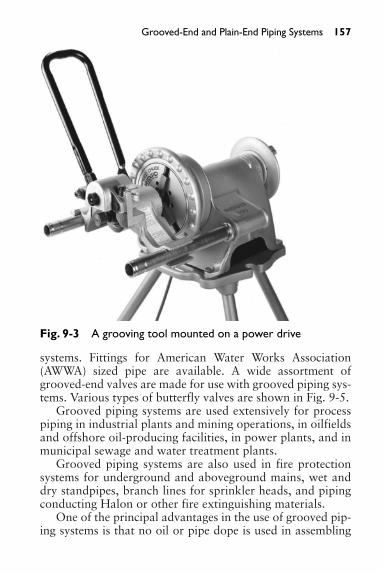
systems. Fittings for American Water Works Association(AWWA) sized pipe are available. A wide assortment ofgrooved-end valves are made for use with grooved piping sys-tems. Various types of butterfly valves are shown in Fig. 9-5.
Grooved piping systems are used extensively for processpiping in industrial plants and mining operations, in oilfieldsand offshore oil-producing facilities, in power plants, and inmunicipal sewage and water treatment plants.
Grooved piping systems are also used in fire protectionsystems for underground and aboveground mains, wet anddry standpipes, branch lines for sprinkler heads, and pipingconducting Halon or other fire extinguishing materials.
One of the principal advantages in the use of grooved pip-ing systems is that no oil or pipe dope is used in assembling
Grooved-End and Plain-End Piping Systems 157
Fig. 9-3 A grooving tool mounted on a power drive

158 Grooved-End and Plain-End Piping Systems
Fig. 9-4 A hand-operated grooving tool (Courtesy of VictaulicCompany of America)
Fig. 9-5 Various types of Victaulic ® butterfly valves (Courtesy ofVictaulic Company of America)

the components of the system, and contamination of the pip-ing from these products is eliminated.
Plain-End Piping Systems for Steel PipeThe Victaulic ® plain-end method can be used to simplifythe installation, maintenance, and repairs of piping systems.No special pipe end preparation is required. Pipe cuts shouldbe square.
Victaulic ® Plain-End Couplings can also be used withbeveled-end pipe. The plain-end system uses grips in the cou-plings, which bite into the pipe ends and secure them, as shownin Fig. 9-6. These couplings are primarily designed for use onstandard weight (Schedule 40) steel pipe. They are not intendedfor use on plastic pipe, plastic-coated pipe, or brittle pipe, suchas asbestos cement or cast iron. They are not intended for useon pipe with a surface hardness greater than 150 Brinnell.
Grooved-End and Plain-End Piping Systems 159
Fig. 9-6 A Victaulic ® standard flexible coupling (Courtesy ofVictaulic Company of America)

160 Grooved-End and Plain-End Piping Systems
Plain-end fittings are available in standard patterns com-mon to the trade. Grooved-end fittings must not be usedwith Victaulic ® Plain-End Couplings shown in Fig. 9-7.
Fig. 9-7 Cutaway view of a Victaulic ® plain-end rigid coupling(Courtesy of Victaulic Company of America)
The Victaulic ® Plain-End Piping System used with thecorrect Victaulic ® fittings and valves is listed for fire protec-tion services by Underwriters Laboratories.
We have explained only Victaulic ® fittings for metallicpiping in this chapter. Victaulic ® fittings are also availablefor use with plain-end high-density polyethylene or poly-butylene pipe.

10. LEARNING TO USE AN INSTRUMENT LEVEL
A skilled pipefitter should have a working knowledge of ele-vations. Especially on new construction, sleeves and boxesmust often be set at exact points in reinforced poured-concrete walls and footings. Underground piping may haveto be installed at an exact level to meet job specifications.
An instrument level is a telescope (Fig. 10-1) mounted ona base equipped with leveling screws (Fig. 10-2). The base isscrewed onto a tripod (Fig. 10-3) when the instrument is inuse. The instrument level can be rotated a full 360° horizon-tally and, when properly adjusted, the level-indicating bub-ble will show that the instrument is level at any point of thecompass, no matter in which direction the instrument ispointed.
161
CROSS-HAIRADJUSTMENT
LEVELINGSCREW A
LEVELINGSCREW B
FOCUSINGKNOB
LEVELINGSCREW C
LEVELINGSCREW D
LEVELINGBUBBLE
Fig. 10-1 An instrument level (Courtesy David White Instruments)

162 Learning to Use an Instrument Level
Adjusting an instrument level must be done very care-fully in order to avoid damage to the instrument. Aftermounting the instrument on the tripod, swing the instru-ment so that the barrel is directly over two opposingscrews (A and C, Fig. 10-2). Both screws should be turnedequally and simultaneously in the same direction until theleveling bubble is centered. Then, swing the barrel 180°.The bubble should still be centered. Next, swing the barrel90° until the barrel is directly over the other two opposingscrews (B and D, Fig. 10-2). Adjust these screws until thebubble is centered. Then, reverse the instrument, turn thebarrel 180° again, still over B and D; the bubble shouldremain centered. Swing it again to A and C and readjustthese until the bubble is again centered. It may be neces-sary to repeat this process several times before the instru-ment is in a level position when pointed in any direction.Do not overtighten the adjusting screws. If the adjustingscrews are overtightened, the bed-plate of the instrumentcan be damaged, thereby preventing leveling of the instru-ment altogether.
ADJUSTING SCREW B
ADJUSTING SCREW A
ADJUSTING SCREW D
ADJUSTING SCREW C
ADJUSTING OPPOSING SCREWSEQUALLY AND SIMUTANEOUSLY
Fig. 10-2 Correct way to adjust leveling screws

CAUTIONIf, after repeated tries, the bubble will not remain centeredwhen the instrument is reversed, the instrument is faulty andshould be repaired. Do not attempt to adjust the screws onthe leveling bubble; this is a job for an instrument repairtechnician.
Learning to Use an Instrument Level 163
Fig. 10-3 A tripod used with an instrument level (Courtesy DavidWhite Instruments)

164 Learning to Use an Instrument Level
One of the first steps when a new building is started is toestablish a “benchmark.” This is usually done by a mechani-cal engineer. The benchmark is a fixed point from which allbuilding measurements are taken, the top of an iron manholein a street, for example. As the building goes up, the bench-mark can be transferred to other locations where it will be vis-ible from any point. This point is then given a number, and allvertical measurements of the building are based on this num-ber. Some architects and mechanical engineers use a numberbased on the height of the area above sea level: 745.00, forinstance. Others may use the number 100.00. The metric sys-tem, consisting of 10ths and 100ths, is used because it is moreaccurate and easier to use than feet and inches. The numberused is not important since it is merely a reference point fromwhich all vertical measurements are made.
Helpful Conversions and EquivalentsTables 10-1 and 10-2 provide helpful aids for converting toand from metric measurements. Table 10-3 shows conver-sions from fractions to decimals.
Table 10-1 Conversion from Metric
Approximate Conversions from Metric Measures
When You Multiply by Symbol Know Length To Find Symbol
mm millimeters 0.04 inches in
cm centimeters 0.4 inches in
m meters 3.3 feet ft
m meters 1.1 yards yd
km kilometers 0.6 miles mi
As an example, if the benchmark is established at 747.00,plans may show a first floor, (ground level) finished height of743.00, a second floor level of 753, and a basement floorlevel of 731.00. Numbers greater than the benchmark showelevations above the bench mark. The finished second floor

will be 6 ft above the benchmark. (747.00 � 6 � 753.00).Numbers lower than the benchmark show elevations belowthe benchmark. The basement floor level will be 16 feetbelow the benchmark. (747.00 – 731.00 � 16.)
When an instrument level is used, it must be set up at apoint from which both the benchmark and the elevation tobe located are visible. An engineer’s rod (Fig. 10-4) markedin 10ths and 100ths of a foot (metric scale) is set up on thebenchmark, and with the instrument leveled and pointed atthe rod, a reading is taken. In the example shown in Fig. 10-5,the reading is 5.25. This is the H.I., or height of the instru-ment, above the benchmark.
Learning to Use an Instrument Level 165
Table 10-2 Conversion to Metric
Approximate Conversions from Metric Measures
When You Multiply by Symbol Know Length To Find Symbol
in inches 2.5 centimeters cm
ft feet 30.0 centimeters cm
yd yards 0.9 meters m
mi miles 1.6 kilometers km
Table 10-3 Conversion from Fractions to Decimals
Fractional Inches Decimal Inches1⁄64 0.0161⁄32 0.0311⁄16 0.0631⁄8 0.1251⁄4 0.251⁄2 0.53⁄4 0.75

166 Learning to Use an Instrument Level
Using the previous numbers, apipefitter must set a sleeve for processpiping in a form for a foundationwall. The sleeve must be centered at2�8� below the finished first floor.How can he pinpoint this location?
First, he will set up his instrumentlevel and take a reading on an engi-neer’s rod placed on the benchmark.This reading shows 5.25, giving anH.I. of 5.25. It is very important thatthe rod be held straight when it isheld to obtain a reading. If the rodis leaning toward the instrument,the reading will be high; if it is lean-ing away, the reading will be low.
Every fitter working with eleva-tions will need an engineer’s rule. A6-ft folding engineer’s rule is a con-version rule with feet and inches onone side and metric scale on the otherside. This is shown in Fig. 10-6. Withyour thumbnail placed on the feetand inches side of the engineer’s rule,turn the rule over to see the equiva-lent metric scale. Example: 2�8�equals 2.68 metric feet. Subtracting2.68 from 743.00 (finished firstfloor) shows that the elevation of thecenterline of the sleeve will be740.32. We know that the H.I. of theinstrument is 5.25 above the bench-mark. We also know that the center-line of the sleeve must be 6�8� belowthe benchmark. If the engineer’s rod
1
2
3
4
5
4
7
8
9
10
11
11
5
1
2
Fig. 10-4 Anengineer’s rod (CourtesyDavid White Instruments)

Learning to Use an Instrument Level 167
H.I.
= 5
.25 B.M
.
B.M
. = B
ENC
HM
AR
KF.F
. = F
INIS
HED
FLO
OR
BOT
TOM
OF
ROD
WIL
L BE
CEN
TER
LIN
E O
F SL
EEV
E
B.M
.
F.F.
11.9
3
4′00
″2′
8″
5
Fig. 10-5 Using an instrument level to mark the correct elevation

168 Learning to Use an Instrument Level
is taken to the form location and lowered until the cross-hairsof the instrument read 11.93 (5.25 � 6.68) and the form ismarked at the bottom of the rod, this mark will be the center-line of the sleeve.
The elevation of each point is shown in Fig. 10-5.
(A)STANDARD RULE
(FT & IN)
(B)ENGINEER'S RULE(10THS & 100THS)
(C)ENGINEER'S ROD(10THS & 100THS)
89
5FT
12 2
1
5
9
84-10
4-11
5 FT
5-1
5-2
5-3
Fig. 10-6 A standard rule, an engineer’s rule, and an engineer’s rod

11. PNEUMATIC CONTROL SYSTEMS
The installation and servicing of pneumatic control systemsfalls within the scope of work of pipefitters. If I were startingout to learn a trade all over again, I would specialize in theinstallation and servicing of pneumatic controls as soon as Ihad completed my apprenticeship or equivalent training as apipefitter. The installation of pneumatic controls is a very spe-cialized field—and a very rewarding one. I’ll explain how andwhere training in this field is available at the end of this chapter.
Although there are many uses for pneumatic controls inmanufacturing facilities, process piping, the aerospace indus-try, fire systems control, theme parks, and numerous otherareas, limited space will not permit the mention of all theuses of these automatic controls. In this chapter, we will bemore concerned with pneumatic systems to control heating/cooling and ventilating systems. The work involved includesthe installation and servicing of air compressors, piping fromcompressors to pneumatically operated thermostats, valves,dampers, humidistats, and auxiliary devices. An air com-pressor specially designed for use with pneumatic controls isshown in Fig. 11-1.
169
Fig. 11-1 An air compressor especially designed for use withpneumatic controls (Courtesy Powerex)

170 Pneumatic Control Systems
Fundamentals of Pneumatic ControlA basic control system consists of a power supply, supplyline, controller, output line, and the controlled device. A sim-plified basic control system is shown in Fig. 11-2. The aircompressor (power supply) supplies pressure to the roomthermostat (controller), which sends an output pressure sig-nal to the damper actuator to position the damper (con-trolled device).
Fig. 11-2 A basic pneumatic control system (Reproduced fromJohnson Controls, Inc.)
Power SourceCompressed air at a constant pressure of 15 to 25 psig(pounds per square in gauge) is used as the power source. Thepower supply is the most important component of the controlsystem. If it fails, the entire system will fail. Pneumatic powerair must be clean, dry, and free of oil, and must be at a con-stant pressure. A refrigerated air dryer (Fig. 11-3) will pro-vide dry air for the control system.
Safe OperationSafe conditions are essential before mechanical equipment maybe allowed to operate. “Fail-safe” pneumatic controls can pre-vent damage caused by freezing or overheating. Spring-loadedactuators and valves cause these devices to return to a fail-safeposition in the event of temperature control failure.
CONTROLLER ROOMTHERMOSTAT
CONTROLLEDDEVICE
DAMPER
DAMPERACTUATOR
OUTPUTLINESUPPLY
LINEAIR COMPRESSOR
POWERSUPPLY
SO

System OperationAll automatic control systems function on the “cause-and-effect” principle. This means that every component in thesystem has an effect on the other components.
In Fig. 11-4 the thermostat (Tr) measures the temperatureof the air surrounding it. As the temperature rises, the thermo-stat causes a reduction of the heat (Hi) being supplied to theroom, which allows the room temperature (Rt) to stop risingor to drop. This affects the thermostat so that it adjusts its influ-ence on heat input until a balance between heat input and heatloss is established, resulting in stabilized room temperature.
Pneumatic Control Systems 171
Fig. 11-3 A Johnson Control’s A-4000 Series refrigerated airdryer (Reproduced from Johnson Controls, Inc.)

172 Pneumatic Control Systems
Thus, one change is dependent onanother change, and a “closed-loop”system has been established.
A closed-loop system is thearrangement of components to allowsystem feedback. For example, aheating unit, valve, and thermostatare arranged so that each componentaffects the other and can react to it.The relationship of “cause and ef-fect,” the interdependence of onething upon another, is called “feed-back.” Feedback makes true auto-matic control possible.
There are three basic elements thatmust be considered when puttingtogether a closed-loop system. Theyare:
1. The Control Agent. The source of energy supplied tothe system can be either hot or cold, such as steam, hotwater, heated air, chilled water, electrical current, orrefrigerant.
2. The Controlled Device. The instrument that receivesthe output signal from the controller and regulates theflow of the Control Agent. It is functionally dividedinto two parts:a. Actuator. Receives the output signal and converts it
into force.b. Regulator. Valve body or damper that regulates the
flow of the Control Agent.
NoteA valve or damper can be either normally open (NO) or nor-mally closed (NC) to regulate the flow of the control agent. Thetype to be used is chosen primarily for “fail-safe” operation.
Rt Tr
Hi
Tr = ROOM THERMOSTATHi = HEAT INPUTRt = ROOM TEMPERATURE
Fig. 11-4 Schematicof components of aclosed-loop system(Reproduced from JohnsonControls, Inc.)
3. Controller Action. The controller that is furnishedmay be either direct acting or reverse acting. The con-troller will allow the system to balance itself.a. Direct Acting. The output signal changes in the
same direction in which the controlled or measuredvariable changes. An increase in the controlledvariable results in an increased output signal.
b. Reverse Acting. The output signal changes in theopposite direction from that in which the controlledor measured variable changes. An increase in the con-trolled variable results in a decreased output signal.
The closed-loop system is the most commonly used sys-tem. A typical closed loop system with a two-position (eitherON or OFF) pneumatic controller is shown in Fig. 11-5. Theclosed loop system (Fig. 11-6) uses a proportional pneumaticcontroller, which holds the valve open to admit just enoughof the heating medium to the heating coil, maintaining theroom temperature at or near the desired level.
Actual Operating SequenceTo put everything we’ve learned in perspective, let’s go toFig. 11-5 to see exactly what happens when the room tem-perature drops.
When the temperature drops below the set point of thethermostat, the thermostat (controller) opens the steam valveto the heating unit, which, in turn, heats the air in the room.Then, room temperature rises, providing feedback to thethermostat. The thermostat closes the steam valve whenroom temperature reaches the top limit of the differential.
DifferentialThe differential is the number of units the controlled vari-able must change before the output signal of a two-positioncontroller changes from minimum to maximum, or viceversa.
Pneumatic Control Systems 173

174 Pneumatic Control Systems
An open-loop system (as shown in Fig. 11-7) is used in cer-tain instances (for example, when more heat is required tomaintain a suitable room temperature as the outdoor temper-ature drops). It is possible to arrange a thermostat to measureoutdoor temperature so as to cause the heat input (boileroperating temperature) of a building to increase as the out-door temperature decreases. The outdoor thermostat cannotmeasure the result of heat input to the room, hence there is nofeedback. Building temperature or individual room tempera-tures would be controlled by one or more indoor thermostats.
All control systems are composed of one or more loops.Most will be closed loops, but some may be open loops or a
DIRECT-ACTINGTHERMOSTAT TWO-POSITION
CONTROLLER
NORMALLY OPENVALVE
FEED
BACK
Typical Closed Loop System with two-position pneumatic controller, Thermostat (controller) measures room temperature and opens valve (controlled device) when temperature falls to lower limit of differential. This admits steam to terminal unit which in turn heats the air in the room. Then, room temperature rises providing feedback to the thermostat which closes valve when temperature reaches top limit of differential.
Fig. 11-5 A closed-loop system with a two-positioncontroller (Reproduced from Johnson Controls, Inc.)

combination of both. The proper combination of these ele-ments must be applied or the closed-loop system will notoperate properly.
It is necessary to understand the difference between closedand open loops in order to appreciate the results that can beexpected. There are no perfect closed loops. In actual controlconditions, outside forces constantly work on the variousparts to change the balance and set the loop cycle in opera-tion to reestablish balance. If this were not the case, therewould be no need for automated control.
Pneumatic Control Systems 175
DIRECT-ACTINGTHERMOSTAT PROPORTIONAL
CONTROLLER
NORMALLY OPENVALVE
FEED
BACK
Typical Closed Loop System with proportional pneumatic controller and normally open valve with 3 to 6 PSIG spring.As in the two-position system, the thermostat controls the valve which supplies the medium to the system, as determined by feedback through room air. However, the proportional thermostat holds the valve open to the proper position to admit just enough of the heating medium (hot water) to the coil of the terminal unit to maintain room temperature at or near the desired level.
Fig. 11-6 A closed loop system with a proportionalcontroller (Reproduced from Johnson Controls, Inc.)

176 Pneumatic Control Systems
To summarize, a closed-loopsystem is one in which each parthas an effect on the next step inthe loop, and each is affected bythe action of the previous step.An open-loop system is one inwhich one or more of the stepshave no direct effect or actionimposed on the following step oris not affected by other steps inthe loop.
ControllersA controller must be sensitive tochanges in the controlled vari-able and respond with a preciseoutput signal of adjustable mag-
nitude to prevent the controlled variable from deviating toomuch from the set point. A controller has two main parts:the measuring or sensing element and the relay, which pro-duces the output signal. Controllers can be classified in twotypes: two-position and proportional.
Two-position control provides full delivery or no deliveryof the power source (either on or off).
Proportional control influences the power source in pro-portion to changes in the controlled variable requirements asmeasured and directed by the controller. For example, a pro-portionally controlled device such as a damper or a valvemay be partially opened or partially closed as directed by thecontroller.
Either type can be used. Selection is dependent on thedesired results.
Measuring ElementsThe measuring element of a controller converts the status orchange in a controlled variable to a useful movement or
Rt
To
Hi
To = OUTDOOR TEMPERATUREHi = HEAT INPUTRt = ROOM TEMPERATURE
Fig. 11-7 Schematic ofcomponents of an open-loop system (Reproduced fromJohnson Controls, Inc.)

variation that will activate the relay to produce an output sig-nal. Three types of elements commonly used in control sys-tems measure temperature, relative humidity, and pressure.
TemperatureTemperature-measuring elements are made in various typesto fit the several kinds of controllers. Wall-mounted ther-mostats normally use bimetal or vapor-filled bellows ele-ments. Remotely mounted or external elements have liquid,gas, or refrigerant-filled bulbs and capillaries. The capillaryor connecting section on bulb types is furnished in variouslengths to allow the controller to be mounted away from themeasured variable.
Bimetal elements are two thin strips of dissimilar metalfused together to form a device that reliably changes itsshape at a constant rate as its ambient temperature changes.Because the two metals bonded together expand and con-tract at vastly different rates, the measuring element, heldstationary at one end, bends as the temperature varies.Thus, temperature measurement is changed into a physicalmovement.
Remote bulb elements are used when temperatures are tobe measured in pipes, tanks, ducts, or relatively inaccessiblelocations or where a hostile environment would be detrimen-tal to the controller. Remote bulb elements are composed ofthree parts: the bulb or temperature-sensitive portion; thecapillary, which transmits the variable temperature signalover its length; and the diaphragm or operating head, whichchanges the temperature measurement into motion.
HumidistatsHumidistats are designed to measure and control the relativehumidity of a building, room, or area. The measuring ele-ments in a humidistat are usually made from materials thatattract water and respond to humidity changes by changingtheir size and/or shape.
Pneumatic Control Systems 177

178 Pneumatic Control Systems
Pneumatic TubingCopper tubing in sizes 1⁄8 in, 3⁄16 in and 1⁄4 in (all O.D., out-side diameter) is used in both inaccessible and accessiblelocations for pneumatic tubing. Pneumatic tubing installedin or under a concrete floor, in a masonry wall, in the plastercoating of a wall, or in the hollow space of a precast concreteplank is considered inaccessible. Polyethylene tubing withbarbed fittings can be used in some installations, providingthat the tubing is installed in a concealed-accessible location.
Training in the Pneumatic Control FieldThe installation, servicing, and calibration of pneumaticcontrol systems is a highly specialized field. The author hasworked closely with Johnson Controls (formerly JohnsonService Co.) personnel in the past and suggests that pipefit-ters interested in receiving training in this field contact:
Johnson Controls InstituteAttn: M45507 E. Michigan StreetMilwaukee, WI 53202
Portions of the text of this chapter are excerpts from vari-ous training manuals furnished by Johnson Controls, Inc. andare reproduced with permission of Johnson Controls, Inc.

12. GAS PIPING
The installation, testing, and connection of gas transmissionlines, gas piping, and gas-fired appliances falls within thescope of work of pipefitters and welders.
To fill a need for a single code that would cover all facets offuel-gas piping and appliance installations, from meter setassemblies or other facilities composing the gas service entranceto consumers’ premises, a National Fuel Gas Code was devel-oped by representatives of the American Gas Association(AGA), the American Society of Mechanical Engineers(ASME), and the National Fire Protection Association (NFPA).The Code was approved by the American National StandardsInstitute (ANSI) and is revised and updated as needed. TheCode is listed as ANSI Z223.1 and NFPA 54. Copies may beobtained from ANSI and NFPA.
The Uniform Plumbing Code contains a section on fuel-gas piping.
The Southern Building Code Congress International hasdeveloped a “Standard Gas Code.”
If a question should arise regarding the installation or ser-vicing of piping or appliances, the local authority (in certaincodes the administrative authority) shall have final jurisdic-tion. Also, the word “shall” is a mandatory term.
Although all gas codes and regulations are designed topromote safety in the installation of piping and the servicingof gas-fueled equipment and appliances, and are, therefore,basically similar, the reader is advised to become thoroughlyfamiliar with the gas code enacted in his or her area of work.
Types of Gases
Manufactured GasThere are several types of manufactured gases. The mostcommon kind is coke-oven gas, a by-product of manufactur-ing of coke from coal. Coke-oven gas has a heating value of525 to 570 Btu (British thermal units) per cubic foot.
179

180 Gas Piping
Mixed GasMixed gas is a mixture of natural gas and any of severaltypes of manufactured gas.
Natural GasNatural gas, in its original state, is lighter than air and willescape upward in the event of leakage. If the leak is within abuilding where escape to the outside is impossible, the risk offire and/or explosion is very high.
Liquid Petroleum GasLiquid petroleum (LP) gas is a fuel found in natural gas andis made up principally of propane or butane or a mixture ofthe two products. When demand is high, many utilities addliquid petroleum gas to natural gas. LP gas under moderatepressure becomes a liquid and is easily transported andstored. At normal atmospheric pressure and temperature,the liquid returns automatically to the gaseous state. Theheat content of LP gas is about three times greater than thatof natural gas and about six times greater than that of mostmanufactured gases. At atmospheric pressure, pure butanevaporizes or returns to gas at 32°F. Pure propane returns togas at –44°F. Under normal conditions, these are the lowesttemperatures at which the liquid turns to gas. For these rea-sons, propane is used more in cold climates; butane is usedmore in mild climates.
LP gas is heavier than air and is colorless. Being heavierthan air, leaking LP gas will pocket in low areas of a room,structure, or area. Explosions and fires resulting in loss oflife and heavy property damage have occurred when a sparkignited pocketed LP gas. Suppliers add odors to LP gas to aidin detecting leaks.
Kinds of PipingThe kinds of piping, metallic or plastic, to be used in an instal-lation shall be determined by the building code or regulation ineffect at the job site and by job specifications drawn up by thearchitect/mechanical engineer and/or gas supplier. The chemical

composition of gases used in an area is usually the determiningfactor. Black steel pipe may be acceptable in one area and notpermitted in another area. For example, whereas regular type Lor type K copper tube may be acceptable in one area, tin-linedtype L or type K copper tube may be required in other areas orby other suppliers. A relatively new innovation in piping mate-rial is the use of CSST, corrugated stainless-steel tubing.
Gas MetersGas meters shall be located in readily accessible spaces andshall be placed in areas where they will not be subjected todamage. The location of gas meters is usually the responsi-bility of the gas supplier.
RegulatorsWhen the gas supply pressure is more than the equipment isdesigned to handle, or varies beyond the design pressure lim-its of the equipment, a line gas pressure regulator shall beinstalled.
Troubleshooting hint:Problem: No gas supply to building.
Regulators are installed in conjunction with outside gasmeters. If the venting connection of the regulator is blockedby snow, ice, or debris, the regulator may not be able to“breathe” (flex), shutting off the gas supply to the building.
Low Pressure ProtectionIf the operation of gas utilization equipment such as a gascompressor might produce a vacuum or a dangerous reduc-tion in gas pressure at the meter, a suitable protective deviceshall be installed. Such devices include, but are not limitedto, mechanical, diaphragm-operated, or electrically operatedlow-pressure shutoff valves.
ValvesGas valves shall be of the lubricated straight-way shutofftype and shall be placed in an accessible location. Valves
Gas Piping 181

182 Gas Piping
controlling appliances shall be located within 3� of suchappliances.
Combustion AirGas-burning appliances or devices require a supply of air forproper combustion. Improper combustion will result in soot-ing, causing a heavy concentration of carbon monoxide.Consult the gas supplier for cubic feet of air required forproper combustion.
Testing MethodsTest pressure shall be measured with either a manometer(Fig. 12-1) or with a pressure-measuring device designed andcalibrated to read, record, or indicate a pressure loss due toleakage during the test.
After test pressure has been applied, the source of pres-sure shall be disconnected from the piping before testingbegins. Test pressure shall be no less than 11⁄2 times the pro-posed working pressure, but not less that 3 psig, irrespectiveof design pressure. When a manometer is used, commonpractice is to lift off the burner on a gas stove, then slide thefree end of the manometer tubing over the burner orifice.The manometer is prepared for use by pouring water intoone side of the tubing until it equalizes at the zero point ofthe gauge. When the water level is equalized at the zeropoint, connect the rubber tubing to the orifice. Open theburner valve or (if testing gas pressure) turn on the gas andobserve the reading on each side of the manometer tube.Figure 12-1 (A) shows the pressure equalized at the zeropoint. Figure 12-1 (B) shows the water column after pressurehas been applied. The reading on the side connected to thetest point shows 21⁄2 in below the zero point. The reading onthe other side shows the water level at 21⁄2 in above the testpoint. Adding the two readings together gives the pressureapplied, 21⁄2 � 21⁄2 � 5. If the water level equalizes duringthe test when using the manometer for testing, the pipe isleaking.
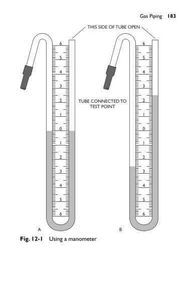
Gas Piping 183
THIS SIDE OF TUBE OPEN
TUBE CONNECTED TOTEST POINT
A B
6
5
4
3
2
6
5
4
3
2
1
1
0
6
5
4
3
2
6
5
4
3
2
1
1
0
Fig. 12-1 Using a manometer

184 Gas Piping
Test duration shall be not less than 1⁄2 hour for each 500cubic feet of pipe volume or fraction thereof. The test dura-tion may be reduced to 10 minutes in a single-family home.Any reduction in test pressure shall be deemed to indicate aleak.
CAUTIONNo substance other than air shall be introduced into the gaspiping for testing purposes. Oxygen must never be used fortesting.
Leak DetectionAny reduction of test pressure indicates a leak. The leak shallbe located by means of an approved combustible gas detec-tor, soap and water, or an equivalent nonflammable solution.Open flames, candles, matches, or any method that couldprovide a source of ignition shall not be used. When the leaksource is located, the leak shall be repaired and the pipingsystem retested.
Thread Compounds (Pipe Dope)Thread compounds (pipe dope) shall be resistant to thechemical constituents of the type of gas to be used. Useonly the type of thread compound recommended by the gassupplier.
Pipe SizingJob specifications or detailed shop drawings usually indicatethe required sizes for piping to fixtures or equipment. Thequantity of gas to be provided at each outlet should be deter-mined from the manufacturer’s Btu rating of the appliance tobe installed. To aid in the selection of correctly sized piping,Table 12-1 lists the approximate gas consumption of theaverage appliance in Btu per hr.
Capacities for different sizes and lengths of pipe in cubicfeet per hour for gas of 0.60 specific gravity, based on apressure drop of 0.3 in of water column, are shown in Table12-2. In adopting a 0.3 in pressure drop, due allowance for

Gas Piping 185
Table 12-1 Approximate Gas Consumption of Typical Appliances
Appliance Input Btu/hr (Approx.)
Boiler or furnace (domestic) 100,000 to 250,000
Range (freestanding, domestic) 65,000
Built-in oven or broiler unit (domestic) 25,000
Built-in top unit (domestic) 40,000
Water heater, automatic storage 55,000(50-gal. tank)
Water heater, automatic instantaneous
2 gal per minute 142,800
4 gal per minute 285,000
6 gal per minute 428,400
Water heater, circulating or side-arm (domestic) 35,000
Refrigerator 3,000
Clothes dryer (domestic) 35,000
Table 12-2 Capacity of Pipe of Different Diameters and Lengths in Cubic Feet per Hour with Pressure
Drop of 0.3� and Specific Gravity of 0.60
Iron-Pipe Sizes
Length of (IPS) (Inch)
Pipe (Feet) 1⁄2 3⁄4 1 11⁄4 11⁄2
15 76 172 345 750 1220
30 52 120 241 535 850
45 43 99 199 435 700
60 38 86 173 380 610
75 77 155 345 545
90 70 141 310 490
(continued)

186 Gas Piping
an ordinary number of fittings should be made. Table 12-2is based on a gas of 0.60 specific gravity. If you wish to usean exact specific gravity for a particular condition, correctthe values in the table by multiplying by �0.6/sg
To obtain the size of piping required for a certain unit,you must first determine the number of cubic feet of gas perhour consumed by the unit.
ExampleIt is necessary to determine the size of the piping in a gas-fired boiler installation when the burner input is 155,000Btu/hr and the heating value per cubic foot of gas is 1000Btu. Assume the distance from the gas meter to the boiler tobe 75 ft.
ft3 of gas/hr �total Btu>hr required by unit
Btu>ft3 of gas
Table 12-2 (continued)
Iron-Pipe Sizes
Length of (IPS) (Inch)
Pipe (Feet) 1⁄2 3⁄4 1 11⁄4 11⁄2
105 65 131 285 450
120 120 270 420
150 109 242 380
180 100 225 350
210 92 205 320
240 190 300
270 178 285
300 170 270
450 140 226
600 119 192

By a substitution of values in the foregoing formula weobtain:
ft3 of gas/hr � 155,000�1000 � 155
From Table 12-2 it will be noted that a 1-in pipe 75 ftlong will handle 155 ft3/hr with 0.3-in pressure drop. Thedetermination of gas pipe sizes for other appliance units canbe made in a similar manner.
ExampleIt is necessary to determine the pipe size of each sectionand outlet of a piping system with a designated pressuredrop of 0.3 in the water column. The gas to be used has aspecific gravity of 0.60 and a heating value of 1000 Btuper cubic foot.
Reference to the piping layout and a substitution of val-ues for maximum gas demand for the various outlets, Fig.12-2, shows that the demand for individual outlets will be asfollows:
Gas demand for outlet A � 55,000⁄1000 � 55 ft3/hrGas demand for outlet B � 3,000⁄1000 � 3 ft3/hrGas demand for outlet C � 65,000⁄1000 � 65 ft3/hrGas demand for outlet D � 116,000⁄1000 � 116 ft3/hr
From the piping layout in Fig. 12-2, it will be noted thatthe length of gas pipe from the meter to the most remote out-let (A) is 105 ft. This is the only distance measurement used.Reference to Fig. 12-2 indicates:
Outlet A supplying 55 ft3/hr requires 1⁄2-in pipe.
Outlet B supplying 3 ft3/hr requires 1⁄2-in pipe.
Outlet C supplying 65 ft3/hr requires 3⁄4-in pipe.
Outlet D supplying 116 ft3/hr requires 3⁄4-in pipe.Section 3 supplying outlets A and B, or 58 ft3/hr,requires 1⁄2-in pipe.
Gas Piping 187

188 Gas Piping
Section 2 supplying outlets A, B, and C, or 123 ft3/hr,requires 3⁄4-in pipe.Section 1 supplying outlets A, B, C, and D, or 239ft3/hr, requires 1-in pipe.
The determination of sizes of gas pipe for other pipinglayouts may be made in a similar manner.
Pipe ThreadsPipe and fittings shall comply with the American Standardfor pipe threads. Pipe with damaged threads shall not beused. All gas piping shall be threaded in accordance withspecifications in Table 12-3.
Branch ConnectionsAll branches should be taken from the top or side of hori-zontal pipes, not from the bottom. When ceiling outlets
GAS METER
GAS RANGE 65,00 BTU/HR
GAS REFRIGERATOR3000 BTU/HR
30′15′
SECTION 3SECTION 2
30′ 15′
15′
50 GAL AUTOMATICWATER HEATER55,000 BTU/HR
30′
FURNACE 116,000 BTU/HR
30′15′
SECTION 1
D
A
B
C
Fig. 12-2 Diagram of a gas-piping layout for a typical domesticinstallation

are taken from horizontal piping, the branch should betaken from the side and carried in a horizontal directionfor a distance of not less than 6 ft. Fig. 12-3 shows theright and the wrong way to connect a drop branch to ahorizontal run.
Gas Piping 189
Table 12-3 Approximate Length of Thread Required forVarious Sizes of Gas Pipe
Approximate Length of ApproximateSize of Pipe Threaded Portion, Number of in Inches in Inches Threads to Be Cut3⁄8 5⁄16 101⁄2 3⁄4 103⁄4 3⁄4 10
1 7⁄8 10
11⁄4 1 11
11⁄2 1 11
2 1 11
21⁄2 11⁄2 12
3 11⁄2 12
4 13⁄4 13
RIGHT WAYWRONG WAY
NOT LESSTHAN 6 IN.
Fig. 12-3 Connection of a drop branch to a horizontal pipe

190 Gas Piping
Pipe SupportsPipe must be properly supported and not subjected to unnec-essary strain. Fig. 12-4 shows a pipe supported by pipe clipsor straps fastened to the building floor joists. The maximumdistance at which these supports should be spaced dependson the pipe size. The following distances between supportsshould never be exceeded, closer spacing being preferable.
3⁄8-in and 1⁄2-in pipe—6 ft3⁄4-in and 1-in pipe—8 ft11⁄4 in and larger (horizontal)—10 ft11⁄4 in and larger (vertical) every floor—level
GAS PIPE ATTATCHED TO JOISTSWITH PIPE CLIPS
Fig. 12-4 Gas piping should be supported from the joists
Pipe shorter than the support spacing listed should alsobe adequately supported. Whenever a branch fitting is used,or wherever there is a change of direction of 45° or more, asupport should be provided within 6 in of one side of theangle fitting.
Pipe straps or iron hooks should not be used for securingpipe larger than 2 in. Beyond this size, when pipe is horizon-tal and is to be fastened to floor joists or beams, pipe hang-ers should be used. When the pipe is to be fastened to a wall,ring hangers and plates should be used.

When pipes run crosswise to joists or beams, do not cutthe timbers deeper than one-fifth of the depth of the timbers,as shown in Fig. 12-5. This cutting should be as near the sup-port of the beam as possible (Fig. 12-6) but in no case shouldit be farther from a support than one-sixth of the span. When
Gas Piping 191
NOT OVER1/5 D
OVER1/5 D
RIGHT WAY WRONG WAY
DD
Fig. 12-5 The notches in joists should never be deeper thanone-fifth the depth of the joists
RIGHT WAY WRONG WAY
SUPPORT
NEARSUPPORT
SUPPORT NEARCENTER OF SPAN
Fig. 12-6 Joists should be notched near a supporting member
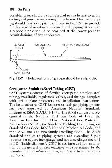
192 Gas Piping
possible, pipes should be run parallel to the beams to avoidcutting and possible weakening of the beams. Horizontal pip-ing should have some pitch, as shown in Fig. 12-7, to providefor drainage of moisture condensed in the piping. A tee witha capped nipple should be provided at the lowest point topermit draining of any condensate.
LOWESTPOINT
HORIZONTALLINE
PITCH FOR DRAINAGE
DRIPNIPPLECAP
Fig. 12-7 Horizontal runs of gas pipe should have slight pitch
Corrugated Stainless-Steel Tubing (CSST)CSST systems consist of flexible corrugated stainless-steeltubing, manifolds, regulators, valves, and fittings, completewith striker plate protectors and installation instructions.The installation of CSST for interior fuel-gas piping systemshas been approved by American National StandardsInstitute ANSI/A.G.A/LC 1-1991. The ANSI standard is rec-ognized in the National Fuel Gas Code of 1988, theAmerican Gas Institute (AGA), National Fire ProtectionAssociation (NFPA), the Southern Building Code CongressStandard Gas Code, BOCA National Mechanical Code, andthe CABO one and two-family Dwelling Code. The ANSIStandard applies to piping systems not exceeding 5 psig(pounds per square inch gauge) and not exceeding a size of 1in I.D. (inside diameter). CSST is not intended for installa-tion by the general public; installers must be trained by themanufacturer, its representatives, or other experienced orga-nizations.

CSST, if approved by the local administrative authorityand/or by the architect or mechanical engineer, can beinstalled in any new or existing residential or commercialbuilding. CSST is especially suited for the retrofitting mar-ket, where limited space, structural obstructions, or otherdifficult installation problems could exist.
Space limitations prohibit an in-depth explanation ofCSST systems in this book. Manufacturers of CSST systemswill furnish informative literature on the installation of theirproducts.
In the absence of a nationally adopted and enforced fuel-gas code, pipefitters installing fuel-gas piping must conformto local regulations or codes in force at the job site.
Gas Piping 193

13. TUNGSTEN INERT GAS WELDING
Tungsten inert gas welding (TIG) can be done on many met-als, but because this book is written for pipefitters andwelders, the information in this chapter pertains specificallyto steel pipe and stainless-steel welding. The TIG arc weldingprocess, also called gas tungsten arc welding (GTAW), uses anonconsumable tungsten electrode to create the electric arcshown in Fig. 13-1. TIG welding can be done manually or,using a machine, automatically. The tungsten electrode isuncoated, and the arc is shielded by an inert gas or gases that
194
ACHF, DCSP, ORDCRP POWER SUPPLY
GAS CUPEITHER CERAMICHIGH-IMPACT OR
WATER-COOLER METAL
INERT GAS SHIELDSELECTRODE ANDWELD PUDDLE
FILLERMETAL
SINGLE PASS WELDSIN THICKNESS UP TO 1⁄2″
MULTIPASS WELDS INHEAVIER THICKNESS
WELDS MADE WITH ORWITHOUT ADDITION OF
FILLER METAL
TUNGSTEN ELECTRODEVIRTUALLY NONCONSUMABLE
WELD SURFACE ISSMOOTH AND CLEAR
Fig. 13-1 Essentials of the TIG welding process

flow around the tungsten tip and over the molten weld. Theeffect of the shielding gas to prevent contamination of theweld is shown in Fig. 13-2. Table 13-1 shows filter recom-mendations.
Fig. 13-2 The effects of shielding gases
Table 13-1 Filter Recommendations (Adapted from ANSISafety Standard Z49.1)
Application Lens Shade No.*
TIG (Tungsten Arc)
Up to 50 amps 10
50 to 150 amps 12
Above 150 amps 14
* As a rule of thumb, start with a shade that is too dark to see the arc zone; then go to alighter shade which gives sufficient view of the arc zone without exerting a strain onyour eyes.
Power Supply for TIG WeldingThe power supply for TIG welding may be either alternatingcurrent (ac) or direct current (dc). Certain weld charac-teristics obtained with each type often make one or the other
HELIUM
2 TO 21⁄2 TIMESAS MUCH GAS FLOW
ARGON
Tungsten Inert Gas Welding 195

better suited to a specific application. Table 13-2 shows therecommended type of current to use for a given job.Recommended electrodes for use with both ac and dc areshown in Table 13-3.
Table 13-2 Current Selection for TIG Welding
Alternating Current* Direct Current
With High-Frequency Straight ReverseMaterial Stabilization Polarity Polarity
Magnesium up to 1⁄8 in thick 1 N.R. 2
Magnesium above 3⁄16 in thick 1 N.R. N.R.
Magnesium Castings 1 N.R. 2
Aluminum up to 3⁄32 in thick 1 N.R. 2
Aluminum over 3⁄32 in thick 1 N.R. N.R.
Aluminum Castings 1 N.R. N.R.
Stainless Steel 2 1 N.R.
Brass Alloys 2 1 N.R.
Silicon Copper N.R. 1 N.R.
Silver 2 1 N.R.
Hastelloy Alloys 2 1 N.R.
Silver Cladding 1 N.R. N.R.
Hard-Facing 1 1 N.R.
Cast Iron 2 1 N.R.
Low-Carbon Steel, 0.015 to 0.030 in. 2** 1 N.R.
Low-Carbon Steel, 0.030 to 0.125 in. N.R. 1 N.R.
(continued)
196 Tungsten Inert Gas Welding

Table 13-2 (continued)
Alternating Current* Direct Current
With High-Frequency Straight ReverseMaterial Stabilization Polarity Polarity
High-Carbon Steel, 0.015 to 0.030 in. 2 1 N.R.
High-Carbon Steel, 0.030 in and up 2 1 N.R.
Deoxidized Copper*** N.R. 1 N.R.
Key1. Excellent operation2. Good operationN.R. Not recommended* Where ac is recommended as a second choice, use about 25% higher current than is
recommended for DCSP.** Do not use ac on tightly jigged part.*** Use brazing flux or silicon bronze flux for 1/4 in and thicker.
Table 13-3 Recommended Electrodes for TIG Welding
Welding Current Range, amp (See Note Below)
AC*DCSP DCRPUsing
Using Pure Thoriated Using Pure Tungsten orElectrode Tungsten Tungsten Thoriated Tungsten Diameter (In) Electrodes Electrodes** Electrodes
0.020 5–15 — — —
0.040 10–60 60–80 15–80 —1⁄16 50–100 100–150 70–150 10–203⁄32 100–160 160–235 150–250 15–301⁄8 150–210 225–325 250–400 25–40
(continued)
Tungsten Inert Gas Welding 197

198 Tungsten Inert Gas Welding
Table 13-3 (continued)
Welding Current Range, amp (See Note Below)
AC*DCSP DCRPUsing
Using Pure Thoriated Using Pure Tungsten orElectrode Tungsten Tungsten Thoriated Tungsten Diameter (In) Electrodes Electrodes** Electrodes5⁄32 200–275 300–425 400–500 40–553⁄16 250–350 400–525 500–800 5–801⁄4 325–475 500–700 800–1000 80–125
* Maximum values shown have been determined using an unbalanced wave transformer.If a balanced wave transformer is used, either reduce these values by about 30 percentor use the next size electrode.This is necessary because of the higher heat input to theelectrode in a balanced wave setup.
** Balled electrode tip ends can best be formed and sustained at these current levels.Note: The recommendations in this chart apply to genuine HELIARC tungsten electrodes
Direct Current WeldingIn direct current welding, the welding current circuit may beconnected as either “straight polarity” or “reverse polarity.”The machine connection for direct current straight polarity(DCSP) is electrode negative and workpiece positive. The elec-trons flow from the electrode to the workpiece. For direct cur-rent reverse polarity welding (DCRP), the machine connectionis electrode positive and workpiece negative. When straightpolarity is used, the electrons exert a considerable heatingeffect on the workpiece; in reverse of polarity welding, wherethe electrode acquires this extra heat, which tends to melt offthe end of the electrode. Therefore, for any given weldingcurrent, DCRP requires a larger diameter electrode than doesDCSP. For example, a 1⁄16-in diameter pure tungsten electrodecan handle 125 amperes of straight polarity welding current.If the polarity were reversed, this amount of current wouldmelt off the electrode and contaminate the workpiece.

Therefore, a 1⁄4-in diameter pure tungsten electrode is neededto handle 125 A (amperes) DCRP.
These opposite heating effects influence not only thewelding action but also the shape of the weld being made.DCSP welding will produce a narrow, deep weld; DCRP,using a larger diameter electrode, gives a wide, relativelyshallow weld. When DCRP is used, the electrons and gasions tend to remove the surface oxides and scale usually pre-sent, thus cleaning the weld area.
Alternating Current WeldingWhen ac welding current is used, half of each ac cycle isDCSP, the other half is DCRP. Moisture, oxides, scale, andso on, on the surface of the workpiece tend to prevent theflow of current in the DCRP half-cycle partially or evencompletely. This is called rectification. If no current were toflow in the reverse polarity direction, all cleaning actionwould be lost. To prevent this from happening, it is commonpractice to introduce into the current a high-voltage, high-frequency, low-power additional current. This high-frequency current jumps the gap between the electrode andthe workpiece and pierces the oxide film, thereby forming apath for the welding current. Superimposing this high-voltage,high-frequency current provides the following advantages:
• The arc may be started without touching the electrodeto the workpiece.
• Better arc stability is obtained.• A longer arc is possible.• Welding electrodes have longer life.• The use of wider current ranges for a specific diameter
electrode is possible.
Types of JointsThe principal basic types of joints used in TIG welding arethe butt, lap, corner, edge, and tee. Regardless of the type ofjoint, the workpiece must be cleaned prior to welding.
Tungsten Inert Gas Welding 199

200 Tungsten Inert Gas Welding
Manual cleaning with a wire brush or chemical solvent isusually sufficient.
Shielding GasesThe objective of TIG is to enable welds to be made withoutthe contaminating influence of the air in the workplace. Toaccomplish this, shielding gas or gases flow from the torchnozzle over and around the weld arc and workpiece. Theshielding gas flows at a prescribed rate measured in cubicfeet per hour (CFH) or liters per hour (LPH). The selectionof the proper gas or gas mixture depends on the materialbeing welded. Gas distributors can supply this information.Argon, an inert gas, is the most commonly used shielding gasfor TIG welding. Its low thermal conductivity produces anarrow, constricted arc column, which allows greater varia-tions in arc length with minimal influence on arc power andweld bead shape. For ac welding applications, argon is pre-ferred over helium because of its superior cleaning action,arc stability, and weld appearance.
Helium is also an inert gas and produces higher arc volt-ages than argon for a given current setting and arc length.This produces a “hotter” arc.
Oxygen and Carbon DioxideThese gases are chemically reactive and should not be usedwith TIG welding. Their high oxidation potential destroysthe tungsten electrode under the heat of the arc.
Gas Flow RateGas flow rate can range from a few CFH to more than 60CFH, depending on the current, the torch size, and sur-rounding drafts. In general, a higher current will require alarger torch and higher flow rates. In addition, gas density,or the weight of the gas relative to the air it needs to dis-place, has a major influence on the minimum flow raterequired to effectively shield the weld. Argon is approxi-mately 1.4 times as heavy as air and 10 times as heavy ashelium. The effect of these densities relative to air is shown

in Fig. 13-2. Argon, after leaving the torch nozzle, forms ablanket over the weld area, whereas helium tends to rise inturbulent fashion around the nozzle. To produce equivalentshielding effectively, the flow of helium must be 2 to 21⁄2times that of argon. The same general relationship is true formixtures of argon and helium, particularly those high inhelium content. Gas flow rate must be selected with care. Itis not productive or economical to use more gas than neces-sary to achieve good shielding. Excess gas pulls air into thewelding arc, often causing porosity in the weld. A flowdevice that limits gas flow to the optimal range is recom-mended.
Gas Preflow and PostflowGas preflow and postflow minimize contamination of theweld zone and electrode. A preflow of shielding gasesremoves moisture, which may have entered the system.Changes in room temperature can cause air to move in andout of the end of a torch while not in use, resulting in mois-ture condensing on the inside of the torch. When the gas isturned on, the moisture mixes with the gas as it leaves thenozzle. A preflow of shielding gas for a period of time beforethe arc is initiated will remove the moisture.
Postflow works in a different way. When the arc is turnedoff, the weld metal begins to cool, but for a few moments theweld metal remains hot enough to be contaminated by the airsurrounding the just-completed weld. To prevent this, theshielding gas is allowed to flow for several seconds after thearc is extinguished. (The length of time depends on the sizeand temperature of the weld.) The postflow of gas also pro-tects the hot electrode from contamination.
Backup Shielding and Trailing ShieldsIt is sometimes necessary to use shielding gas on the under-side of a weld to prevent oxidation of the hot weld bottom.Backup shielding gas is used to purge the air from the insideof piping. This procedure prevents contamination of the
Tungsten Inert Gas Welding 201

202 Tungsten Inert Gas Welding
backside of a weld while the pipe is being welded from theoutside. In some instances, the welding may occur too fastfor the shielding gas to protect the weld until it has cooled.As the arc moves on, the solidified weld metal remains hotand oxidizes. A trailing gas shield can be use used to preventthis oxidation from occurring.
The Advantages of TIG over Shielded Metal Arc WeldingIn any type of welding, the best obtainable weld is one thathas the same chemical, metallurgical, and physical proper-ties as the base metal itself. To obtain such conditions, themolten weld puddle must be protected from the atmo-sphere during the welding operation; otherwise, atmo-spheric oxygen and nitrogen will combine readily with themolten weld metal and result in a weak, porous weld. InTIG welding, the weld zone is shielded from the atmo-sphere by an inert gas, which is fed through the weldingtorch. Either argon or helium may be used. Argon is widelyused because of its general suitability for a wide variety ofmetals and for the lower flow rates required. Helium pro-vides a hotter arc, allowing 50 to 60 percent higher arcvoltage for a given arc length. This extra heat is especiallyuseful when welding heavy sections. Gas mixtures of argonand helium are used to provide the benefits of both gases.The use of nonconsumable tungsten electrodes and inertshielding gases produces the highest-quality welds of anyopen-arc welding process. Welds are bright and shiny, withno slag or spatter, and require little or no post-weld clean-ing. The inert gases (argon, helium, or a combination of thetwo) can provide 100 percent protection from the atmo-sphere, making TIG welds stronger, more ductile and morecorrosion resistant than welds made with ordinary arc-welding processes. Since no flux is used, corrosion due toflux entrapment cannot occur. TIG is easily used in allwelding positions and provides excellent puddle control.Various combinations of dissimilar metals can be weldedusing the TIG process.

Starting the ArcIn ac welding, the electrode does not have to touch theworkpiece to start the arc. The superimposed high-fre-quency current jumps the gap between the welding elec-trode and the work, thus establishing a path for thewelding current to follow. To strike an arc, first turn on thepower supply and hold the torch in a horizontal positionabout 2 in above the workpiece, as shown in Fig. 13-3.Then, quickly swing the torch down toward the workpieceso that the end of the electrode is about 1⁄8 in above theworkpiece. The arc will then strike. This downwardmotion should be made rapidly to provide the maximumamount of gas protection to the weld zone. The torch position
Tungsten Inert Gas Welding 203
POSITION OF TORCHWHEN WELDING
WORKPIECE
1⁄8″2″
Fig. 13-3 Torch position for the starting swing

204 Tungsten Inert Gas Welding
WORKPIECEWORKPIECE
DIRECTIONOF WELDING
A. DEVELOP THE PUDDLE
B. MOVE TORCH BACK
C. ADD FILLER METAL
D. REMOVE ROD
E. MOVE TORCH TO LEADINGEDGE OF PUDDLE
75°
15°
75°
15°
Fig. 13-4 Steps in making a TIG weld (Courtesy Praxair, Inc.)

Tungsten Inert Gas Welding 205
at the time the arc strikes, and the steps involved in makingTIG welds are shown in Fig. 13-4.
In dc welding, the same motion is used for striking anarc. In this case, the electrode must touch the workpiece inorder for the arc to start. As soon as the arc is struck, theelectrode must be withdrawn approximately 1⁄8 in abovethe workpiece to avoid contaminating the electrode in themolten puddle. High frequency is sometimes used to start adc arc, eliminating the need to touch the workpiece. Thehigh frequency is automatically turned off when the arc isstarted.
The arc can be struck on the workpiece itself or on aheavy piece of copper or scrap steel and then carried to thestarting point of the weld. Do not use a carbon block forstarting the arc; the electrode would be contaminated,causing the arc to wander. When you are starting to weldwith a hot electrode, the action must be very rapid,because the arc tends to strike before the torch is in properposition.
Stopping the ArcTo stop an arc, snap the electrode back up to the horizontalposition. This motion must be made rapidly to prevent thearc from marring or damaging the weld’s surface or theworkpiece. When current density of the electrode is at a suf-ficiently high level, the entire end of the electrode will be in amolten state and completely covered by the arc. When toolow a current density is used, only a small area of the elec-trode becomes molten, resulting in an unstable arc, whichhas poor directional characteristics and is difficult for theoperator to control. Too high a current density results inexcessive melting of the end of the electrode. Striking an arcwith a carbon pencil or on a carbon block is a primary causeof arc wandering. When the carbon touches molten tung-sten, tungsten carbide is formed. Tungsten carbide has alower melting point than pure tungsten and forms a large

206 Tungsten Inert Gas Welding
molten ball on the end of the electrode. This ball, in effect,reduces the current density at the electrode end, and arcwandering then occurs. The electrode can also be contami-nated by touching it to the workpiece or filler rod. Whenelectrode contamination occurs in any form, it is best tobreak off the contaminated end and regrind the end of theelectrode.
Arc WanderingWith the torch held stationary, the points at which the arcleaves the electrode and impinges upon the workpiece mayoften shift and wander without apparent reason. This isknown as “arc wandering” and is generally attributed to oneof the following causes:
• Low electrode current density• Carbon contamination of the electrode• Magnetic effects• Air drafts
The first two causes are distinguished by a very rapidmovement of the arc from side to side, generally resulting ina zig-zag weld pattern. Magnetic effects, the third cause,generally displace the arc to one side or the other along theentire length of the weld. The fourth cause creates varyingamounts of arc wandering, depending upon the amount ofair draft present.
TIG Pipe Welding1. Root pass, rolled joint. This will be a standard vee
joint with a 37° bevel on each side, a 1⁄16 in nose and a1/16 to 3/32-in spacing.After the joint has been tacked (four tacks 90° apart),the arc is struck on the side and carried down to thebottom of the joint. Filler metal is added until the pud-dle bridges over the gap. After the puddle bridges the
joint, the arc is held until the puddle flattens out andbecomes wedge shaped, straight across the front androunded at the rear. When this takes place, the puddlehas fully penetrated the joint.
2. Filler pass. Weave or zig-zag beads can be used on lowalloy steel in the rolled position. Stringer beads laidparallel to the joint are used for stainless-steel pipe.Weave or zig-zag welds can be used on low alloy steelpipe. Stringer beads are required for stainless-steelheavy wall pipe in all positions and for low alloy pipein the vertical-fixed position.
3. Finish Pass. The final pass should be about 1⁄16 inabove the surface of the pipe.
The chief advantage of TIG welding for the fabricationof piping systems is that the welds are smooth, fully pene-trated, and free from obstructions or crevices on theinside. TIG welds are stronger and more resistant to corro-sion than welds made by any other process. Anotheradvantage is that in today’s economy production costs arevery important, and TIG welding results in savings inlabor costs by eliminating the labor involved in removal ofslag and spatters.
Safety Precautions• Keep your head out of the fumes while welding.• Provide sufficient ventilation.• Welding inside tanks, boilers, or confined spaces
requires the use of an air-supplied hood or a hosemask.
• Ground all electrical equipment and the workpiece(Fig. 13-5).
These are only a few of the many safety precautionswelders and pipefitters should take. For complete informa-tion regarding safety on the job, follow the recommendations
Tungsten Inert Gas Welding 207

208 Tungsten Inert Gas Welding
found in: American National Standard Z49.1, “Safety inWelding and Cutting” available from the American WeldingSociety, P.O. Box 351040, Miami, FL 33135, and also the“National Electrical Code,” NFPA No. 70, available fromthe National Fire Protection Association, Batterymarch Park,Quincy, MA 02269.
TO APPROVEDGROUND
WORK LEAD
POWERSUPPLY
TO APPROVEDEARTH
GROUND
WORK TABLE
Fig. 13-5 Ground all electrical equipment and the workpiece

209
14. TROUBLESHOOTING TIPS FOR ARC WELDING
Trouble Cause Remedy
Welder runs but Wrong relay heaters. See renewal part soon stops. recommendations.
Welder is overloaded. Considerableoverload can becarried only for a short time.
Duty cycle is too high. Do not operatecontinually atoverload currents.
Leads are too long Should be large or too narrow in enough to carrycross-section. welding current
without excessivevoltage drop.
Power circuit is Check for one single-phased. dead fuse or line.
Ambient temperature Operate at reduced is too high. loads where
temperatureexceeds 100°F.
Ventilation is blocked. Check air inlet and exhaustopenings.
Welding arc is Current setting is Check setting and loud and too high. output with spatters ammeter.excessively.
(continued)

210 Troubleshooting Tips for Arc Welding
(continued)
Trouble Cause Remedy
Polarity is wrong. Check polarity: try reversing it, oruse an electrodeof oppositepolarity.
Welding arc is Current is too low. Check the output sluggish. and current
recommended forthe electrodebeing used.
Poor connections. Check all electrode-holder, cable, andground-cableconnections. Strapiron is poorground return.
Cable is too long or Check cable voltagetoo small. drop and change
cable.
Touching the set Frame not grounded. Ground it solidly.gives a shock.
Generator Any part of field Find faulty contact control fails circuit may be and repair it.to vary short-circuited or current. open-circuited.
Welder starts Wrong direction of See “Initial but will not rotation. Starting.”deliver Brushes are worn Check that all welding or missing. brushes bear current. on commutator
with sufficienttension.

Troubleshooting Tips for Arc Welding 211
(continued)
Trouble Cause Remedy
Brush connections Tighten them.are loose.
Open field circuit. Check connection to rheostat, resistor, and auxiliarybrush studs.
Series field and Check it with armature circuit test lamp or bellis open. ringer.
Wrong driving speed. Check nameplate against speed ofmotor or belt drive.
Dirt on grounding field Clean and coils. reinsulate.
Welding terminal Electrode holder shorted. or cable
grounded.
Welder Electrode or ground Clean and tighten generating but connection loose. all connections.current falls Poor ground. Check ground-off when return circuit.welding. Brushes worn off. Replace with
recommendedgrade. Sand to fit.Blow out carbondust.
Weak brush spring Replace or pressure. readjust brush
springs.Brush not properly Sand brushes to fit.
fitted.
(continued)

212 Troubleshooting Tips for Arc Welding
(continued)
Trouble Cause Remedy
Brushes in backwards. Reverse.Wrong brushes used. See renewal part
recommendations.Brush pigtails Replace brushes.
damaged.Rough or dirty Turn down or
commutator. clean commutator.Motor connection Check all
single-phased. connections.
Welder will not Power circuit is Check voltage.start (starter dead.not operating). Broken power lead. Repair.
Wrong supply Check nameplate voltage. against supply.
Open power Close.switches.
Blown fuses. Replace.Overload relay Let set cool. Remove
tripped. cause of overloading.
Open circuit to starter Repair.button.
Defective operating Replace it.coil.
Mechanical Remove it.obstruction in contactor.
Welder will not Wrong motor Check connection start (starter connections. diagram.operating). Wrong supply voltage. Check nameplate
against supply.Rotor stuck. Try turning it by
hand.

(continued)
Trouble Cause Remedy
Power circuit is Replace fuse; single-phased. repair open line.
Starter is single- Check contact of phased. starter tips.
Poor motor Tighten it.connection.
Open circuit in Repair it.windings.
Starter operates Fuse is too small. Should be two to and blows three times rated fuse. motor current.
Short circuit in motor Check starter and connections. motor leads for
insulation fromground and fromeach other.
Troubleshooting Tips for Arc Welding 213

214
15. PIPE WELDERS’ DEFINITIONS
Alloy Steel—A steel that owes its distinctive propertiesto elements other than carbon.Area of a Circle—The measurement of the surfacewithin a circle. To find the area of a circle, multiply theproduct of the radius times the radius by pi (3.142).Commonly written A � �r2.Braze Weld or Brazing—A process of joining metalsusing a nonferrous filler metal or alloy, the meltingpoint of which is higher than 800°F but lower thanthat of the metals to be joined.Butt Weld—A circumferential weld in pipe, fusing theabutting pipe walls completely from inside wall to out-side wall.Carbon Steel—A steel that owes its distinctive proper-ties chiefly to the various percentages of carbon (as dis-tinguished from the other elements) which it contains.Circumference of a Circle—The measurement aroundthe perimeter of a circle. To find the circumference,multiply pi (3.142) by the diameter. (Commonly writ-ten as d).Coefficient of Expansion—A number indicating thedegree of expansion or contraction of a substance. Thecoefficient of expansion is not constant and varieswith changes in temperature. For linear expansion, itis expressed as the change in length of one unit oflength of a substance having a one-degree rise in tem-perature. A Table of Expansion (see Appendix, TableA.11) is generally used to determine expansion or con-traction within a piping system.Corrosion—The gradual destruction or alteration of ametal or alloy caused by direct chemical attack or byelectrochemical reaction.

Pipe Welders’ Definitions 215
Creep—The plastic flow of pipe within a system; thepermanent set in metal caused by stresses at high tem-peratures. Generally associated with a time rate ofdeformation.Diameter of a Circle—A straight line drawn throughthe center of a circle from one extreme edge to theother. Equal to twice the radius.Ductility—The property of elongation above the elas-tic limit but under the tensile strength. A measure ofductility is the percentage of elongation of the frac-tured piece over its original length.Elastic Limit—The greatest stress that a material canwithstand without a permanent deformation afterrelease of the stress.Erosion—The gradual destruction of metal or othermaterial by the abrasive action of liquids, gases, solids,or mixtures thereof.Radius of a Circle—A straight line drawn from thecenter to the extreme edge of a circle.Socket Fitting—A fitting used to join pipe in which thepipe is inserted into the fitting. A fillet weld is thenmade around the edge of the fitting and the outsidewall of the pipe at the junction of the pipe and fitting.Soldering—A method of joining metals using fusablealloys, usually tin and lead, that have melting pointsunder 700°F.Strain—Change in the shape or size of a body pro-duced by the action of a stress.Stress—The intensity of the internal, distributed forcesthat resist a change in the form of a body. When exter-nal forces act on a body, they are resisted by reactionswithin the body, which are termed stresses. A tensilestress is one that resists a force tending to pull a bodyapart. A compressive stress is one that resists a force

216 Pipe Welders’ Definitions
tending to crush a body. A shearing stress is one thatresists a force tending to make one layer of a bodyslide across another layer. A torsional stress is one thatresists forces tending to twist a body.Tensile Strength—The maximum tensile stress that amaterial will develop. The tensile strength is usuallyconsidered to be the load in pounds per square inch atwhich a test specimen ruptures.Turbulence—Any deviation from parallel flow in apipe due to rough inner walls, obstructions, or direc-tional changes.Velocity—A time rate of motion in a given directionand sense, usually expressed in feet per second.Volume of a Pipe—The measurement of the spacewithin the walls of the pipe. To find the volume of apipe, multiply the length (or height) of the pipe by theproduct of the inside radius times the inside radius bypi (3.142). Commonly written as V � �r2h.Welding—A process of joining metals by heating themuntil they are fused together or by heating and apply-ing pressure until there is a plastic joining action. Fillermetal may or may not be used.Yield Strength—The stress at which a material exhibitsa specified limiting permanent set.
217
16. DEFINITIONS OF HEATING AND AIR-CONDITIONING TERMS
The following terms apply to heating and air conditioning,both in work and in designing of systems.
Absolute Humidity—The weight of water vapor ingrains actually contained in one cubic foot of the mix-ture of air and moisture.
Absolute Pressure—The actual pressure above zero;the atmospheric pressure added to the gauge pressure.It is also expressed as a unit pressure such as poundsper square inch (psig).
Absolute Temperature—The temperature of a sub-stance measured above absolute zero. To express atemperature as absolute temperature, add 460° to thereading of a Fahrenheit thermometer or 273° to thereading of a centigrade thermometer.
Absolute Zero—The temperature (–460°F. approx.) atwhich all molecular motion of a substance ceases andat which the substance contains no heat. Scientists areworking to achieve a temperature of absolute zero, butthis goal may be unattainable.
Air—An elastic gas; a mixture of oxygen and nitrogenwith slight traces of other gases. It may contain mois-ture known as humidity. Dry air weighs 0.075 lb/ft3.Air expands or contracts approximately 1⁄490th of itsvolume for each degree rise or fall in temperature from32°F.
Air Change—The number of times in an hour that theair in an area is changed, either by mechanical meansor by infiltration of outside air.Air Cleaner—A device designed for removal of air-borne impurities such as dust, dirt, smoke, and fumes.

218 Definitions of Heating and Air-Conditioning Terms
Air Conditioning—The simultaneous control of tem-perature, humidity, air cleaning, and air movementand distribution within an area.
Air Infiltration—The leakage of air into a buildingthrough cracks, crevices, doors, windows, and otheropenings.
Air Vent—A device designed to purge air from radia-tion or piping in a steam or hot-water heating system.
Atmospheric Pressure—The weight upon a given areaof a column of air one square inch in cross sectionextending upward to the outer limits of the atmo-sphere. Atmospheric pressure at sea level is approxi-mately 14.7 lb/sq in. Atmospheric pressure is less atthe top of a mountain, more below sea level.
Boiler—In heating terms, a closed vessel in whichwater is heated to produce steam or hot water forheating purposes.
Boiler Heating Surface—The heat-transmitting sur-faces of a boiler in contact with hot water or steam onone side and hot gases or fire on the other side.
Boiler Horsepower—The equivalent evaporation of34.5 lb of water per hour at 212°F. to steam at 212°F.This equals a heat output of 33,475 British thermalunits (Btu) per hour.
British Thermal Unit—The quantity of heat requiredto raise the temperature of one pound of water onedegree Fahrenheit.
Bucket Trap (Inverted)—A float trap with a float openat the bottom. When the air or steam in the bucket hasbeen replaced by condensate, the bucket loses itsbouyancy and sinks. As it sinks, it opens a valve topermit condensate to be returned to the boiler.
Bucket Trap (Open)—An open bucket trap is open atthe top. Water surrounding the bucket keeps it floating,

Definitions of Heating and Air-Conditioning Terms 219
but as condensate drains into the bucket, the bucketsinks, opening an outlet allowing steam pressure toforce the condensate out of the trap.Calorie (Small)—The quantity of heat required toraise one gram of water one degree centigrade.Calorie (Large)—The quantity of water required toraise one kilogram of water one degree centigrade.Celsius—A thermometer scale at which the freezingpoint of water is 0° and its boiling point is 100°.Chimney Effect—The tendency of air in a duct to riseor fall as density of the air varies with temperature.Coefficient of Heat Transmission (U)—The amount ofheat (Btu) transmitted in one hour, from air to air, persquare foot of wall, floor, roof, or ceiling for a differ-ence in temperature of one degree Fahrenheit betweenthe air on the inside and outside of the wall, floor,roof, or ceiling.
Comfort Line—The effective temperature at which thelargest percentage of adults feel comfortable.Comfort Zone—The range of effective temperatures atwhich the largest percentage of adults feel comfortable.Condensate—In steam heating, the water formed assteam cools. One pound of condensate per hour isequal to approximately 4 ft2 of steam heating surface(240 Btu per hour per square foot).Conductivity (Thermal)-k—The amount of heat (Btu)transmitted in one hour through one square foot of ahomogenous material one inch thick for a difference intemperature of one degree Fahrenheit between the twosurfaces of the material.Convection—The transmission of heat by the circula-tion, either natural or forced, of a liquid or a gas suchas air. Natural convection is caused by the differenceof weight or density of a hotter or colder fluid or air.

220 Definitions of Heating and Air-Conditioning Terms
Convector—A concealed or enclosed heating or cool-ing unit transferring heat or cooled air by the processof convection.Convertor—A vessel or device for heating water withsteam without mixing the two. The process is calledindirect heating.Cooling Leg—A length of uninsulated pipe throughwhich condensate flows to a trap and that has enoughcooling surface to allow the condensate to dissipateadequate heat to prevent “flashing” when the trapopens. (See Flash.)Degree Day—A unit that is the difference between65°F and the daily average temperature when the lat-ter is below 65°F. The “degree days” in any one day isequal to the number of degrees Fahrenheit that theaverage temperature for that day is below 65°F.Dew-Point Temperature—The air temperature corre-sponding to saturation (100 percent relative humidity)for a given moisture content. It is the lowest tempera-ture at which air can retain the moisture it contains.Direct-Indirect Heating Unit—A heating unit that ispartially enclosed, the enclosed portion being used toheat air which enters from outside the room.Direct Return System (Hot Water)—A two-pipe hotwater heating system in which the water, after it haspassed through a heating unit, is returned to the boileralong a direct path so that the total distance traveledby the water from each radiator is the shortest distancefeasible. Each circuit in a system will vary in length.Domestic Hot Water—Hot water used for purposesother than house heating, such as bathing, cooking,laundering, and dishwashing.Down-Feed One-Pipe Riser (Steam)—A pipe that car-ries steam downward to the heating units and intowhich condensate from the heating units drains.

Definitions of Heating and Air-Conditioning Terms 221
Down-Feed System (Steam)—A steam heating systemin which the supply mains are above the level of theheating systems which they serve.
Dry-Bulb Temperature—The air temperature as deter-mined by an ordinary thermometer.
Dry Return (Steam)—A return pipe in a steam heatingsystem that carries both condensation water and air.
Dry Saturated Steam—Saturated steam that carries nowater in suspension.
Equivalent Direct Radiation (EDR)—The amount ofheating surface that will give off 240 Btu per hourwhen filled with a heating medium at 215°F and sur-rounded by air at 70°F. (The equivalent square feet ofheating surface may have no direct relation to theactual surface area.)
Fahrenheit—A thermometer scale at which the freez-ing point of water is 32° and its boiling point is 212°above zero.
Flash—The instant passing into steam of water at ahigh temperature when the pressure it is under isreduced so that its temperature is above that of itsboiling point for the reduced pressure. For example, ifhot condensate is discharged by a trap into a low-pressure return or into the atmosphere, a percentageof the water will be immediately transformed intosteam. Another term for flash is reevaporation.
Float and Thermostatic Trap—A float trap with athermostatic element for permitting the escape of airinto the return line.
Float Trap—A steam trap that is operated by a float.When enough condensate has drained into the trapbody, the float is lifted, opening a port, thereby permit-ting the condensate to flow into the return and lettingthe float drop. When the float has been sufficiently

222 Definitions of Heating and Air-Conditioning Terms
lowered, the port is closed again. Temperature does notaffect the operation of a float trap.Gauge Pressure—The pressure above that of theatmosphere and indicated on the gauge. It is expressedas pounds per square inch gauge (psig).Head—(1) Pressure expressed in feet of water. Onefoot of water column exerts a pressure of .43 lbs. (2)That form of energy into which all other forms may bechanged. Heat always flows from a body of highertemperature to a body of lower temperature. (SeeLatent Heat, Sensible Heat, Specific Heat, Total Heat,Heat of the Liquid.)Heat of the Liquid—The heat (Btu) contained in a liq-uid by virtue of its temperature. The heat of the liquidfor water is zero at 32°F and increases approximately1 Btu for every degree rise in temperature.Heat Unit—In the foot-pound-second system, theBritish thermal unit (Btu); in the centimeter-gram-second system, the calorie (cal).Heating Medium—A substance, such as water, steam,or air, used to convey heat from any source of heat tothe heating units from which the heat is dissipated.Heating Surface—The exterior surface of a heating unit.Heating Unit—Any device that transmits heat from aheating system or source to an area and its occupants.Horsepower—A unit to indicate the time rate of doingwork equal to 550 ft-lb per second or 33,000 ft-lb perminute. One horsepower equals 2545 Btu per hour or746 watts.Humidistat—An instrument that controls the relativehumidity of an area.
Humidity—Water vapor present in air.Insulation (Thermal)—Material with a high resistanceto heat flow.

Definitions of Heating and Air-Conditioning Terms 223
Latent Heat of Evaporation—The heat (Btu perpound) necessary to change one pound of liquid intovapor without raising its temperature. In round num-bers, this is equal to 960 Btu per pound of water.
Latent Heat of Fusion—The heat necessary to meltone pound of a solid without raising the temperatureof the resulting liquid. The latent heat of fusion ofwater (melting one pound of ice) is 144 Btu.
Mechanical Equivalent of Heat—The mechanicalenergy equivalent to 1 Btu, which is equal to 778 ft-lb.
Mil-Inch—One one-thousandth of an inch (0.001).
One-Pipe Supply Riser (Steam)—A pipe that carriessteam to a heating unit and that also carries the con-densation from the heating unit. In an upfeed riser,steam travels upward and condensate travels down-ward, while in a downfeed system, both steam andcondensate travel down.
One-Pipe System (Hot Water)—A hot-water heatingsystem in which one pipe serves both as a supply mainand a return main. The heating units have separatesupply and return connections but both connect backto one main.
One-Pipe System (Steam)—A steam heating system inwhich both steam and condensate flow in the samemain. Each heating unit has only one connectionwhich serves as both steam supply and condensatereturn connection.
Overhead System—Any steam or hot water system inwhich the supply main is above the heating units. Witha steam system, the return must be below the heatingunits; with a water system, the return may be abovethe heating units.
Pressure—Force per unit area, such as pounds persquare inch. Usually refers to unit static gauge pressure.

224 Definitions of Heating and Air-Conditioning Terms
(See Static, Velocity, Total Pressure and AbsolutePressure.)
Pressure Reducing Valve—A device for changing thepressure of a gas or liquid from a higher pressure to alower pressure.
Radiant Heating—A heating system in which the heat-ing is accomplished by radiation only.
Radiation—The transmission of heat in a straight linethrough space.
Radiator—A heating unit exposed to view and locatedwithin the room to be heated. A radiator transfersheat by radiation to objects “it can see” and by con-duction to the surrounding air, which, in turn, is circu-lated by natural convection.
Reducing Valve—(See Pressure Reducing Valve.)
Reevaporation—(See Flash.)
Refrigeration, Ton of—(See Ton of Refrigeration.)
Relative Humidity—The amount of moisture in a givenquantity of air compared with the maximum amount ofmoisture the same quantity of air could hold at thesame temperature. It is expressed as a percentage.
Return Mains—The pipes that return the heatingmedium from the heating units to the source of heatsupply.
Reverse-Return System (Hot Water)—A two-pipe hotwater heating system in which the water from the sev-eral heating units is returned along paths arranged sothat all radiator circuits of the system are practicallyof even length.
Sensible Heat—Heat that only increases the tempera-ture of objects as opposed to latent heat.Specific Heat—In the foot-pound-second system, theamount of heat required to raise one pound of a

Definitions of Heating and Air-Conditioning Terms 225
substance one degree Fahrenheit. In the centimeter-gram-second system, the amount of heat (cal) requiredto raise one gram of a substance one degree centi-grade. The specific heat of water is 1.Square Foot of Heating Surface—(See EquivalentDirect Radiation.)Static Pressure—The pressure that tends to burst apipe. It is used to overcome the frictional resistance toflow through a pipe. It is expressed as a unit pressureand may be either in absolute or gauge pressure. It isfrequently expressed in feet of water column or (in thecase of pipe friction) in mil-inches of water column perfoot of pipe.
Steam—Water in the vapor phase. The vapor formedwhen water has been heated to its boiling point, corre-sponding to the pressure it is under. (See also DrySaturated Steam, Wet Saturated Steam, SuperheatedSteam.)
Steam Heating System—A heating system in which theunits give up their heat to the area by condensing thesteam furnished to them by the boiler or other source.
Steam Trap—A device for allowing the passage of con-densate and air but preventing the passage of steam.(See Thermostatic, Float, Bucket Trap.)
Superheated Steam—Steam heated above the tempera-ture corresponding to its pressure.
Supply Mains—The pipes through which the heatingmedium flows from the boiler or source of supply tothe runouts and risers leading to the heating units.
Thermostat—An instrument that responds to changesin temperature and that directly or indirectly controlsarea temperature.
Thermostatic Trap—A steam trap that opens inresponse to a drop in temperature, for example, when

226 Definitions of Heating and Air-Conditioning Terms
cold condensate or air reaches it, and closes whensteam reaches it. The temperature-sensitive element isusually a sealed bellows or series of diaphragm cham-bers containing a small quantity of volatile liquid.Ton of Refrigeration—The heat that must be extractedfrom one ton, (2000 lb) of water at 32°F to change itinto ice at 32°F in 24 hrs. It is equal to 288,000 Btu/24hr, 12,000 Btu/hr, or 200 Btu/minute.Total Heat—The latent heat of vaporization added tothe heat of the liquid with which it is in contact.Total Pressure—The sum of the static and velocitypressures. It is also used as the total static pressureover an entire area (that is, the unit pressure multi-plied by the area on which it acts).Trap—(See Steam Trap, Thermostatic Trap, FloatTrap, Bucket Trap.)Two-Pipe System (Steam or Water)—A heating systemin which one pipe is used for the supply main andanother for the return main. The essential feature of atwo-pipe hot water system is that each heating unitreceives a direct supply of the heating medium, whichcannot have served a preceding heating unit.Unit Pressure—Pressure per unit area as pounds persquare inch (psig).Upfeed System (Hot Water or Steam)—A heating sys-tem in which the supply mains are below the level ofthe heating units that they serve.Vacuum Heating System (Steam)—A one- or two-pipeheating system equipped with the necessary accessoryapparatus to permit the pressure in the system to gobelow atmospheric.Vapor—Any substance in the gaseous state.Vapor Heating System (Steam)—A two-pipe heat-ing system that operates under pressure at or near

Definitions of Heating and Air-Conditioning Terms 227
atmospheric and that returns the condensate to theboiler or receiver by gravity.Velocity Pressure—The pressure used to create thevelocity of flow in a pipe.Vent Valve (Steam)—A device for permitting air to beforced out of a heating unit or pipe, which then closesagainst water and steam.Vent Valve (Water)—A device that permits air to bepushed out of a pipe or heating unit but that closesagainst water.Wet Bulb Temperature—The lowest temperature thata water-wetted body will attain when exposed to anair current.Wet Return (Steam)—That part of a return main of asteam heating system that is completely filled withcondensation water.Wet Saturated Steam—Saturated steam containingsome water particles in suspension.

17. GLOSSARY OF TERMS RELATING TOPLASTIC PIPING
Adhesive—A substance capable of holding materialstogether by surface attachment.Adhesive, Solvent—An adhesive having a volatileorganic liquid as a vehicle. See Solvent Cement.Aging—(1) The effect on materials of exposure to anenvironment for an interval of time. (2) The process ofexposing materials to an environment for an intervalof time.Antioxidant—A compounding ingredient added to aplastic composition to retard possible degradationfrom contact with oxygen (air), particularly in pro-cessing at or exposure to high temperatures.Artificial Weathering—The exposure of plastics tocyclic laboratory conditions involving changes in tem-perature, relative humidity, and ultraviolet radiantenergy, with or without direct water spray, in anattempt to produce changes in the material similar tothose observed after long-term continuous outdoorexposure.
NOTEThe laboratory exposure conditions are usually intensifiedbeyond those encountered in actual outdoor exposure in anattempt to achieve an accelerated effect. This definition doesnot involve exposure to special conditions such as ozone,salt spray, industrial gases, and so on.
Bell End—The enlarged portion of a pipe that resem-bles the socket portion of a fitting and that is intendedto be used to make a joint by inserting a piece of pipeinto it. Joining may be accomplished by solventcements, adhesives, or mechanical techniques.
228

Glossary of Terms Relating to Plastic Piping 229
Beam Loading—The application of a load to a pipebetween two points of support, usually expressed inpounds, and the distance between the centers of thesupports.Burst Strength—The internal pressure required tobreak a pipe or fitting. This pressure will vary with therate of build-up of the pressure and the time duringwhich the pressure is held.Cement—See Adhesive and Solvent cement.Chemical Resistance—(1) The effect of specific chem-icals on the properties of plastic piping with respect toconcentration, temperature, and time of exposure. (2)The ability of a specific plastic pipe to render servicefor a useful period in the transport of a specific chem-ical at a specified concentration and temperature.Chlorinated Poly (Vinyl Chloride) Plastics—Plasticsmade by combining chlorinated poly (vinyl chloride)with colorants, fillers, plasticizers, stabilizers, lubri-cants, and other compounding ingredients.Cleaner—A medium-strength organic solvent, such asmethylethyl ketone, used to remove foreign matterfrom pipe and fitting joint surfaces.Compound—The intimate admixture of a polymer orpolymers with other ingredients such as fillers, soften-ers, plastics, catalysts, pigments, dyes, curing agents,stabilizers, antioxidants, and so on.Copolymer—See Polymer.Creep—The time-dependent part of strain resultingfrom stress, that is, the dimensional change caused bythe application of load, over and above the elasticdeformation and with respect to time.Cv—See Flow coefficient.
Deflection Temperature—The temperature at which aspecimen will deflect a given distance at a given load

230 Glossary of Terms Relating to Plastic Piping
under prescribed conditions of test. See ASTM D648.Formerly called heat distortion.
Degradation—A deleterious change in the chemicalstructure of a plastic. (See also Deterioration.)Deterioration—A permanent change in the physicalproperties of a plastic evidenced by impairment ofthese properties.
NOTEBurst strength, fiber stress, hoop stress, hydrostatic designstress, long-term hydrostatic strength, hydrostatic strength(quick) long-term burst, ISO equation, pressure, pressurerating, quick burst, service factor, strength stress, and sus-tained pressure test are related terms.
Elasticity—That property of plastic materials byvirtue of which they tend to recover their original sizeand shape after deformation.
NOTEIf the strain is proportional to the applied stress, the materialis said to exhibit Hookean or ideal elasticity.
Elastomer—A material that at room temperature canbe stretched repeatedly to at least twice its originallength and that, immediately upon release of thestress, will return with force to its approximate origi-nal length.Elevated Temperature testing—Tests on plastic pipeabove 23°C (73°F).Environmental stress cracking—Cracks that developwhen the material is subjected to stress in the presenceof specific chemicals.Extrusion—a method whereby heated or unheatedplastic forced through a shaping orifice becomes onecontinuously formed piece.

Glossary of Terms Relating to Plastic Piping 231
NOTEThis method is commonly used to manufacture thermoplas-tic pipe.
Failure, Adhesive—Rupture of an adhesive bond, suchthat the plane of separation appears to be at the adhe-sive-adherend interface.Fiber Stress—The unit stress, usually in pounds persquare inch (psig), in a piece of material that is sub-jected to an external load.Filler—A relatively inert material added to a plastic tomodify its strength, permanence, working properties,or other qualities, or to lower costs.Flow Coefficient, or Cv—Valve coefficient of flowrepresenting the flow rate of water in gallons perminute which will produce a 1-psig pressure dropthrough the valve.Full-Port Valve—A valve in which the resistance toflow, in the open position, is equal to an equivalentlength of pipe.Fungi Resistance—The ability of plastic pipe to with-stand fungi’s growth and/or their metabolic productsunder normal conditions of service or laboratory testssimulating such conditions.Heat Joining—Making a pipe joint by heating theedges of the parts to be joined so that they fuse andbecome essentially one piece, with or without theaddition of additional material.Hoop Stress—The tensile stress, usually in pounds persquare inch (psig), in the circumferential orientation inthe wall of the pipe when the pipe contains a gas orliquid under pressure.Hydrostatic Design Stress—The estimated maximumtensile stress in the wall of the pipe in the circumferen-tial orientation due to internal hydrostatic pressure

232 Glossary of Terms Relating to Plastic Piping
that can be applied continuously with a high degree ofcertainty that failure of the pipe will not occur.Hydrostatic Strength (Quick)—The hoop stress calcu-lated by means of the ISO equation at which the pipebreaks due to an internal pressure build-up, usuallywithin 60 to 90 seconds.Impact, Izod—A specific type of impact test madewith a pendulum-type machine. The specimens aremolded or extruded with a machined notch in the cen-ter. (See ASTM D256.)ISO Equation—An equation showing the interrela-tions between stress, pressure, and dimensions in pipe,namely.
S � [P (ID � t)/2t] or [P (OD � t)/2t]where S � stress
P � pressureID � average inside diameter
OD � average outside diametert � minimum wall thickness
Reference: “ISO R161–1960 Pipes of Plastic Materialsfor the Transport of Fluids (Outside Diameters andNominal Pressures) Part I,” Metric Series.Joint—The location at which two pieces of pipe or apipe and a fitting are connected. The joint may bemade by an adhesive, a solvent-cement, or a mechani-cal device such as threads or a ring seal.Long-Term Burst—The internal pressure at which apipe or fitting will break due to a constant internalpressure held for 100,000 hours (11.43 years).Long-Term Hydrostatic Strength—The estimated tensilestress in the wall of the pipe in the circumferential orien-tation (hoop stress) that when applied continuously willcause failure of the pipe at 100,000 hours (11.43 years).
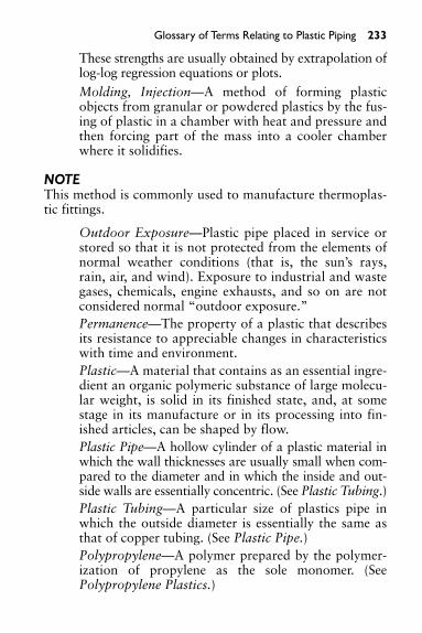
Glossary of Terms Relating to Plastic Piping 233
These strengths are usually obtained by extrapolation oflog-log regression equations or plots.Molding, Injection—A method of forming plasticobjects from granular or powdered plastics by the fus-ing of plastic in a chamber with heat and pressure andthen forcing part of the mass into a cooler chamberwhere it solidifies.
NOTEThis method is commonly used to manufacture thermoplas-tic fittings.
Outdoor Exposure—Plastic pipe placed in service orstored so that it is not protected from the elements ofnormal weather conditions (that is, the sun’s rays,rain, air, and wind). Exposure to industrial and wastegases, chemicals, engine exhausts, and so on are notconsidered normal “outdoor exposure.”Permanence—The property of a plastic that describesits resistance to appreciable changes in characteristicswith time and environment.Plastic—A material that contains as an essential ingre-dient an organic polymeric substance of large molecu-lar weight, is solid in its finished state, and, at somestage in its manufacture or in its processing into fin-ished articles, can be shaped by flow.Plastic Pipe—A hollow cylinder of a plastic material inwhich the wall thicknesses are usually small when com-pared to the diameter and in which the inside and out-side walls are essentially concentric. (See Plastic Tubing.)Plastic Tubing—A particular size of plastics pipe inwhich the outside diameter is essentially the same asthat of copper tubing. (See Plastic Pipe.)Polypropylene—A polymer prepared by the polymer-ization of propylene as the sole monomer. (SeePolypropylene Plastics.)

234 Glossary of Terms Relating to Plastic Piping
Polypropylene Plastics—Plastics based on polymersmade with propylene as essentially the sole monomer.Poly (Vinyl Chloride)—A polymer prepared by thepolymerization of vinyl chloride as the sole monomer.Poly (Vinyl Chloride) Plastics—Plastics made by com-bining poly (vinyl chloride) with colorants, fillers,plasticizers, stabilizers, lubricants, other polymers,and other compounding ingredients. Not all of thesemodifiers are used in pipe compounds.Pressure—When expressed with reference to pipe, theforce per unit area exerted by the medium in the pipe.Pressure Rating—The estimated maximum pressurethat the medium in the pipe can exert continuouslywith a high degree of certainty that failure of the pipewill not occur.Primer—Strong organic solvent, preferably tetrahy-drofuran, used to dissolve and soften the joint surfacesin preparation for and prior to the application of sol-vent cement. Primer is usually tinted purple.PVDF—A crystaline, high molecular weight polymerof vinylidene fluoride, containing 59 percent fluorineby weight.Quick Burst—The internal pressure required to bursta pipe or fitting due to an internal pressure build-up,usually within 60 to 90 seconds.Schedule—A pipe size system (outside diameters andwall thicknesses) originated by the iron pipe industry.Self-Extinguishing—The ability of a plastic to resistburning when the source of heat or flame that ignitedit is removed.Service Factor—A factor that is used to reduce astrength value to obtain an engineering design stress.The factor may vary depending on the service condi-tions, the hazard, the length of service desired, and theproperties of the pipe.

Solvent Cement—In the plastic piping field, a solventadhesive that contains a solvent that dissolves or soft-ens the surfaces being bonded so that the bondedassembly becomes essentially one piece of the sametype of plastic.Solvent Cementing—Making a pipe joint with a sol-vent cement. (See Solvent Cement.)Stress—When expressed with reference to pipe, theforce per unit area in the wall of the pipe in the cir-cumferential orientation due to internal hydrostaticpressure.Sustained Pressure Test—A constant internal pressuretest for 1000 hours.Thermoplastic—A plastic that is thermoplastic inbehavior. Capable of being repeatedly softened byincrease of temperature and hardened by decrease oftemperature.Throttling Valve—A valve that is used for the controlof the flow rate.Union—A device placed in a pipeline to facilitate dis-assembly of the system.Vinyl Chloride Plastics—Plastics based on polymers ofvinyl chloride or copolymers of vinyl chloride withother monomers, the vinyl chloride being in greatestamount by mass.Weld- or Knit-Line—A mark on a molded plastic partformed by the union of two or more streams of plasticflowing together.
Glossary of Terms Relating to Plastic Piping 235


APPENDIX: MISCELLANEOUS INFORMATION
This appendix contains miscellaneous information invalu-able to workers in the piping trades.
INFORMATION ON APPRENTICESHIP TRAININGIN VARIOUS U.S. STATES AND CANADA
There are apprenticeship training programs in most U.S. statesand in Canada. Some of the most noted are listed below.
WashingtonSeattle Area Plumbing and Pipefitting Industry595 Monster Road SW Suite 100Renton WA 98055-2807(425) 271-5900UA Business Office(425) 277-6680email: www.ualocal32.comhttp://Lni.wa.gov/scc/apprenticeship/default.htmhttp://Lni.wa.gov/sca/apprenticeship.org
CaliforniaSan Jose Pipe Trades Training Center ApprenticeshipProgramhttp://www.sbaypipe.org/trnappro.htm
CanadaMinistry of Education, Ministry of Training, Collegesand Universities1-888-562-4769website: www.edu.gov.ca
237

238 Appendix: Miscellaneous Information
Search the Web for more information: pipe tradesapprenticeship
Vocational schools, public and private, on or above thehigh school level, also offer classes on building trades.
In Ontario, the Ministry of Training, Colleges andUniversities, through its Workplace Support Services offices,helps tradespeople to obtain recognition of their trade quali-fications and experience, or to enter an apprenticeship.Tradespeople who have enough related work experience tomeet Ontario standards and who pass a written examinationreceive a Certificate of Qualification.
There are two categories of trades: those for which certi-fication is mandatory and those for which it is voluntary.
Skilled Trades for Which Certification Is MandatoryTo work in certain trades in Ontario, you must have aCertificate of Qualification or be a registered apprentice (seesection on apprenticeship). The following are trades forwhich certification is mandatory:
Alignment and Brakes TechnicianAutobody and Collision Damage Repairer (Branch 1)Autobody Repairer (Branch 2)Automotive Electronic Accessory Technician
• Automotive Service Technician• Electrician (Construction and Maintenance)• Electrician (Domestic and Rural)• Fuel and Electrical Systems Technician• Hairstylist• Mobile Crane Operator (Branch 1)• Mobile Crane Operator (Branch 2)• Motorcycle Mechanic• Plumber

• Refrigeration and Air-Conditioning Mechanic• Sheet Metal Worker• Steamfitter• Tower Crane Operator• Transmission Technician• Truck and Coach Technician• Truck-Trailer Service Technician
Skilled Trades for Which Certification Is VoluntaryYou do not need a Certificate of Qualification to work invarious other trades in Ontario. Employers and unions inthese trades may, however, ask for a Certificate ofQualification. Trades for which certification is voluntaryinclude:
• Air-Cooled and Marine Engine Mechanic• Arborist• Assistant Cook• Automotive Machinist• Automotive Painter• Baker• Boat Motor Mechanic• Brick and Stone Mason• Cement Mason• Construction Boilermaker• Construction Millwright• Cook• Electronics Service Technician• Farm Equipment Mechanic• Fitter (Structural Steel/Platework)• General Machinist
Appendix: Miscellaneous Information 239

240 Appendix: Miscellaneous Information
• Glazier and Metal Mechanic• Nursery Greenhouse Worker• Industrial Electrician• Industrial Mechanic (Millwright)• Industrial Woodworker• Ironworker• Junior Baker• Lather• Marine and Small-Powered Equipment Mechanic• Mouldmaker• Painter and Decorator (Commercial and Residential)• Painter and Decorator (Industrial)• Patissier• Pattern Maker• Printer• Small Engine Technician• Sprinkler and Fire Protection Installer• Tool and Die Maker
Steps in Obtaining a Certificate of Qualification
1. Contact a Workplace Support Services office (see listof offices, on the reverse) to book an appointmentwith a training consultant.
2. Bring the following documents with you to yourappointment:• Social Insurance Number card• Letter(s) from current or past employers, written
on company letterhead and dated, providing thecompany name and address, the exact dates of youremployment, your job title, and a detailed descrip-tion of your duties

• Letter(s) from the union(s) to which you havebelonged (if applicable), with the same informationas noted above
• Certificates, diplomas, or licenses• Official school transcripts from your training, if
available, that contain course descriptions
If your documents are not in English, they must betranslated and signed by an official translator who hasseen the originals. For assistance, contact theAssociation of Interpreters and Translators of Ontarioat 1-800-234-5030.
3. The training consultant will look at your documentsand tell you whether you have the necessary skills andexperience to write the Certificate of Qualificationexamination. If your trade is a compulsory trade, youwill be given a Letter of Permission, which is a tempo-rary license. The Letter of Permission, which is validfor 90 days, allows you to work until you write theexam. If you do not have the necessary skills and expe-rience to write the examination, you will be advised toenter an apprenticeship training program.
4. Pass the written examination. Note that the passingmark is 70 percent.
ApprenticeshipIf you do not have or cannot prove that you have enoughrelated work experience in the trade in which you would liketo work, you may be required to complete an apprenticeship.Apprentices receive a specific number of hours of on-the-jobtraining in a skilled trade. Most of the time is spent on prac-ticing skills in the workplace. The rest is spent on studyingtheory in a classroom, usually at a local community college.
Apprentices are responsible for finding an employer whois willing to oversee their work throughout the apprentice-ship. As an apprentice, you are an employee and, therefore,
Appendix: Miscellaneous Information 241

242 Appendix: Miscellaneous Information
you will be paid for your work. What you receive will be apercentage of the wages of a licensed tradesperson. Appre-nticeship applicants can find employers in the Yellow Pages,through newspaper or Internet ads, or through unions.
To find out more about apprenticeship training, contactone of the Workplace Support Services offices listed below.
Note:Most trades require that you have the equivalent of anOntario Grade 12 education before you enter an apprentice-ship program. If you need to have your educational docu-ments assessed, contact World Education Services through itsWeb site, at www.wes.org, or by telephone, at 416-972-0070.
Workplace Support Services Offices
Central District
Toronto — (416) 326-5800Pickering — (905) 837-7721Mississauga — (905) 279-7333Barrie — (705) 737-1431
Western District
Hamilton — (905) 521-7764Brantford — (519) 756-5197St. Catharines — (905) 704-2991London — (519) 675-7788Owen Sound — (519) 376-5790Sarnia — (519) 542-7705Waterloo — (519) 571-6009Windsor — (519) 973-1441Chatham — (519) 354-2766

Eastern District
Ottawa — (613) 731-7100Brockville — (613) 342-5481Cornwall — (613) 938-9702Kingston — (613) 545-4338Pembroke — (613) 735-3911Peterborough — (705) 745-1918Belleville — (613) 968-5558
Northern District
Sault Ste. Marie — (705) 945-6815North Bay — (705) 495-8515Sudbury — (705) 564-3030Timmins — (705) 235-1950Thunder Bay — (807) 345-8888Kenora — (807) 468-2879
This information has been compiled by the Access toProfessions and Trades Unit of the Ministry of Training,Colleges and Universities.
For more information, visit the Web site at www.edu.gov.on.ca or contact us at [email protected]. Youmay also call us on the Training Hotline at 1-800-387-5656or at (416) 326-5656.
ABBREVIATIONS APPLYING TO THE PIPING TRADES
The following abbreviations conform to the practice of theAmerican Standard Abbreviations for Scientific and Engi-neering Terms, ASA Z10.1.
Appendix: Miscellaneous Information 243

244 Appendix: Miscellaneous Information
Abbreviation Explanation
abs Absolute
AGA American Gas Association
AISI American Iron and Steel Institute
Amer Std American Standard
API American Petroleum Institute
ASA American Standards Association
ASHVE American Society of Heating andVentilating Engineers
ASME American Society of MechanicalEngineers
ASTM American Society for Testing Materials
avg Average
AWWA American Water Works Association
B or Bé Baumé
B & S Bell and spigot or Brown & Sharpe(gauge)
bbl Barrel
Btu British thermal unit(s)
C Centigrade
Cat Catalogue
cfm Cubic feet per minute
cfs Cubic feet per second
CI Cast iron
CS Cast steel (not recommended forabbreviation)
Comp Companion
cu ft (ft3) Cubic feet
cu in (in3) Cubic inch(es)
C to F Center to face
(continued)

Abbreviation Explanation
deg or ° Degree(s)
°C Degrees centigrade
°F Degrees Fahrenheit
Diam Diameter
Dwg Drawing
ex-hy Extra-heavy
F&D Faced and drilled
F Fahrenheit
F to F Face to face
Fig Figure
Flg Flange or flanges
Flgd Flanged
G Gage or gauge
gal Gallon
Galv Galvanized
gpm or gal per min Gallons per minute
Hex Hexagonal
Hg Mercury
Hr Hour
IBBM Iron body bronze (or brass) mounted
I.D. Inside diameter
IPS Iron pipe size (now obsolete—see NPS)
Kw Kilowatt(s)
lb Pound(s)
Max Maximum
Mfr Manufacturer
MI Malleable iron
Min Minimum
(continued)
Appendix: Miscellaneous Information 245

246 Appendix: Miscellaneous Information
(continued)
Abbreviation Explanation
MSS Manufacturers Standardization Society(of Valve and Fittings Industry)
Mtd Mounted
NEWWA New England Water Works Association
NPS Nominal pipe size (formerly IPS foriron pipe size)
OD Outside diameter
OS&Y Outside screw and yoke
OWG Oil, water, gas (see WOG)
psig Pounds per square inch, gage
Red Reducing
Scd Screwed
Sched or sch Schedule
sec Second
SF Semifinished
Spec Specification
sq Square
SSP Steam service pressure
SSU Seconds Saybolt Universal
Std Standard
Trans Transactions
WOG Water, oil, gas (see OWG)
Wt Weight
WWP Working water pressure
XS Extra strong
XXS Double extra strong

PROPERTIES OF AIR
Dry Air
Weight Cu Ft (F3)per Cu Ft Btu Absorbed of Air (F3) of Ratio to per Cu Ft RaisedDry Air Volume (F3) of Air 1°F by
Temperature °F in Pounds at 70°F per °F 1 Btu
0 .08636 .8680 .02080 48.08
10 .08453 .8867 .02039 49.05
20 .08276 .9057 .01998 50.05
30 .08107 .9246 .01957 51.10
40 .07945 .9434 .01919 52.11
50 .07788 .9624 .01881 53.17
60 .07640 .9811 .01846 54.18
70 .07495 1.0000 .01812 55.19
80 .07356 1.0190 .01779 56.21
90 .07222 1.0380 .01747 57.25
100 .04093 1.0570 .01716 58.28
110 .06968 1.0756 .01687 59.28
120 .06848 1.0945 .01659 60.28
130 .06732 1.1133 .01631 61.32
140 .06620 1.1320 .01605 62.31
150 .06510 1.1512 .01578 63.37
160 .06406 1.1700 .01554 64.35
170 .06304 1.1890 .01530 65.36
180 .06205 1.2080 .01506 66.40
(continued)
Appendix: Miscellaneous Information 247

248 Appendix: Miscellaneous Information
(continued)
Saturated Air
Cu FtWeight of of Air
Vapor Press. Vapor per Btu Absorbed RaisedInches of Cu Ft (F3) per Cu Ft (F3) 1°F by
Temperature °F Mercury in Pounds of Air per °F 1 Btu
0 0.0383 0.000069 0.02082 48.04
10 0.0631 0.000111 0.02039 49.50
20 0.1030 0.000177 0.01998 50.05
30 0.1640 0.000276 0.01955 51.15
40 0.2477 0.000409 0.01921 52.06
50 0.3625 0.000587 0.01883 53.11
60 0.5220 0.000829 0.01852 54.00
70 0.7390 0.001152 0.01811 55.22
80 1.0290 0.001576 0.01788 55.93
90 1.4170 0.002132 0.01763 56.72
100 1.9260 0.002848 0.01737 57.57
110 2.5890 0.003763 0.01716 58.27
120 3.4380 0.004914 0.01696 58.96
130 4.5200 0.006357 0.01681 59.50
140 5.8800 0.008140 0.01669 59.92
150 7.5700 0.010310 0.01663 60.14
160 9.6500 0.012956 0.01664 60.10
170 12.2000 0.016140 0.01671 59.85
180 15.2900 0.019940 0.01682 59.45
BARLOW’S FORMULA
Barlow’s formula is used to find the relationship betweeninternal fluid pressure and stress in the pipe wall. It is simpleto use and is conservative; the results are safe. Barlow’s

formula is sometimes known as the “outside diameter” for-mula because it utilizes the outside diameter of the pipe.Bursting tests on commercial steel pipe of the commonlyused thicknesses have shown that Barlow’s formula predictsthe pressure at which the pipe will rupture with an accuracywell within the limits of uniformity of commercial pipethickness.
where: P � internal units pressure, psigS � unit stress, psigD � outside diameter of pipe, int � wall thickness, in
BOILING POINTS OF WATER AT VARIOUSPRESSURES
Boiling Boiling BoilingVacuum Point Vacuum Point Gauge Point
29 79.62 14 181.82 0 212
28 99.93 13 184.61 1 215.6
27 114.22 12 187.21 2 218.5
26 124.77 11 189.75 3
25 133.22 10 192.19 4 224.4
24 140.31 9 194.50 5
23 146.45 8 196.73 6 229.8
22 151.87 7 198.87 7
21 156.75 6 200.96 8 234.8
20 161.19 5 202.25 9
19 165.24 4 204.85 10 239.4
(continued)
P �2 � t � S
D
Appendix: Miscellaneous Information 249

250 Appendix: Miscellaneous Information
(continued)
Boiling Boiling BoilingVacuum Point Vacuum Point Gauge Point
18 169.00 3 206.70 15 249.8
17 172.51 2 208.50 25 266.8
16 175.80 1 210.25 50 297.7
15 178.91 75 320.1
100 337.9
125 352.9
200 387.90
V � Vacuum in inches of Mercury; B.P. � Boiling point of water; Gauge � psig (poundsper square inch gauge)
PIPE CLAMPS
Type Looks Like Type Looks Like
Beam Clamp Pipe Roll and Plate
Side Beam Single Pipe RollClamp
Welded Beam Riser ClampAttachment
"C" Clamp Double Belt Pipe Clamp
(continued)

(continued)
Type Looks Like Type Looks Like
Eye Socket Anchor Chair
Angle and Socket ClampChannel Clamp
COLORS AND APPROXIMATE TEMPERATUREFOR CARBON STEEL
Approximate Color Temperature
Black Red 990°F
Dark Blood Red 1050°F
Dark Cherry Red 1175°F
Medium Cherry Red 1250°F
Full Cherry Red 1375°F
Light Cherry, Scaling 1550°F
Salmon, Free Scaling 1650°F
Light Salmon 1725°F
Yellow 1825°F
Light Yellow 1975°F
White 2220°F
Appendix: Miscellaneous Information 251

252 Appendix: Miscellaneous Information
CRANE SIGNALS FOR MOBILE ANDOVERHEAD CRANES
Standard hand signals for controlling crane operations.ANSI/ASME B30.5 Mobile and Locomotive Cranes. (Reproducedby permission of the American Society of Automotive Engineers)
SWING. Arm extended, point withfinger in direction of swing of boom.
STOP. Arm extended, palm down,move arm back and forth horizontally.
TRAVEL. Arm extended forward,hand open and slightly raised, makepushing motion in direction of travel.
DOG EVERYTHING. Clasp hands infront of body.
(continued)

Appendix: Miscellaneous Information 253
HOIST. With forearm vertical, fore-finger pointing up, move hand insmall horizontal circle.
LOWER. With arm extended down-ward, forefinger pointing down, movehand in small horizontal circle.
USE WHIPLINE (Auxiliary Hoist).Tap elbow with one hand; then useregular signals.
RAISE BOOM. Arm extended, fingers closed, thumb pointingupward.
(continued)

254 Appendix: Miscellaneous Information
USE MAIN HOIST. Tap fist on head;then use regular signals.
LOWER BOOM. Arm extended,fingers closed, thumb pointingdownward.
RAISE THE BOOM AND LOWERTHE LOAD. With arm extended,thumb pointing up, flex fingers in andout as long as load movementis desired.
LOWER THE BOOM AND RAISETHE LOAD. With arm extended,thumb pointing down, flex fingers inand out as long as load movement isdesired.
(continued)

Appendix: Miscellaneous Information 255
EMERGENCY STOP. Both armsextended, palms down, move armsback and forth horizontally.
MOVE SLOWLY. Use one hand togive any motion signal and place otherhand motionless in front of handgiving the motion signal. (Hoist slowlyshown as example.)
TRAVEL (Both Tracks). Use bothfists in front of body, making acircular motion about each other,indicating direction of travel, forwardor backward. (For land cranes only.)
RETRACT BOOM (TelescopingBooms). Both fists in front of bodywith thumbs pointing toward eachother.
(continued)
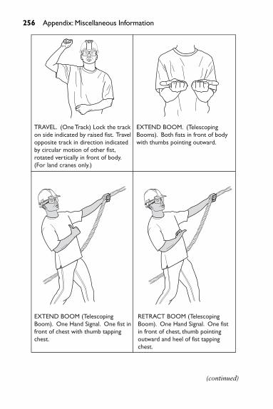
256 Appendix: Miscellaneous Information
(continued)
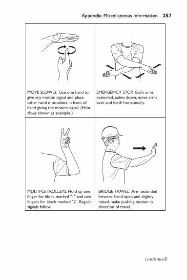
Appendix: Miscellaneous Information 257
MOVE SLOWLY. Use one hand togive any motion signal and placeother hand motionless in front ofhand giving the motion signal. (Hoistslowly shown as example.)
EMERGENCY STOP. Both armsextended, palms down, move armsback and forth horizontally.
MULTIPLE TROLLEYS. Hold up onefinger for block marked "1" and twofingers for block marked "2". Regularsignals follow.
BRIDGE TRAVEL. Arm extendedforward, hand open and slightlyraised, make pushing motion indirection of travel.
(continued)

258 Appendix: Miscellaneous Information
CUBIC FEET TO U.S. GALLONS, IMPERIALGALLONS, AND LITERS
Cu Ft U.S. Gal Imp. Gal Liters
1 7.5 6.2 28
2 15.0 12.5 57
3 22.4 18.7 85
4 29.9 24.9 113
5 37.4 31.2 142
6 44.9 37.4 170
7 52.4 43.6 198
8 59.8 49.9 227
9 67.3 56.1 255
10 74.8 62.4 283
20 149.6 124.7 566
30 224.4 187.1 849
40 299.2 249.4 1133
50 374.0 311.8 1416
60 448.8 374.1 1699
70 523.6 436.5 1982
80 598.4 498.8 2265
90 673.2 561.2 2548
100 748.0 623.6 2832
200 1496.1 1247.1 5663
300 2244.2 1870.7 8495
400 2992.2 2494.2 11,327
500 3740.3 3117.8 14,158
600 4488.3 3741.3 16,990
700 5236.4 4364.9 19,822
(continued)

Appendix: Miscellaneous Information 259
Cu Ft U.S. Gal Imp. Gal Liters
800 5984.4 4988.4 22,653
900 6732.5 5612.0 25,485
1000 7480.5 6235.5 28,317
2000 14,961.0 12,471.0 56,633
3000 22,441.6 18,706.5 84,950
4000 29,922.1 24,942.0 113,266
5000 37,402.6 31,177.5 141,583
6000 44,883.1 37,413.0 169,900
7000 52,363.6 43,648.5 198,216
8000 59,844.1 49,884.0 226,533
9000 67,324.7 56,119.5 254,849
10,000 74,805.2 62,355.0 283,166
20,000 149,610.4 124,710.0 566,332
30,000 224,415.6 187,065.0 849,498
40,000 299,220.8 249,420.0 1,132,664
50,000 374,025.9 311,775.0 1,415,830
60,000 448,831.1 374,130.0 1,698,996
70,000 523,636.3 436,485.0 1,982,162
80,000 598,441.5 498,840.0 2,265,328
90,000 673,246.7 561,195.0 2,548,494
100,000 748,051.9 623,550.0 2,831,660

260 Appendix: Miscellaneous Information
DISC
HARG
E—FI
RE S
TREA
MS
No.
11⁄8-
in
Hos
eP
ress
ure
at H
ose-
Con
nect
ion
in p
ound
s p
er s
quar
e in
ch
Feeb
le S
trea
ms
Ord
inar
y Fi
re S
trea
ms
Unu
sual
ly S
tron
g St
ream
s
Noz
zles
1020
3040
5060
7080
9010
011
012
013
014
015
0
189
129
157
182
202
222
240
257
272
287
300
314
326
339
351
217
825
831
436
440
444
448
051
454
457
460
062
865
267
870
2
326
738
747
154
660
666
672
077
181
686
190
094
297
810
1710
53
435
651
662
872
880
888
896
010
2810
8811
4812
0012
5613
0413
5614
04
544
564
578
591
010
1011
1012
0012
8513
6014
3515
0015
7016
3016
9517
55
653
477
494
210
9212
1213
3214
4015
4216
3217
2218
0018
8419
5620
3421
06
762
390
310
9912
7414
1415
5416
8017
9919
0420
0921
0021
9822
8223
7324
57
871
210
3212
5614
5616
1617
7619
2020
5621
7622
9624
0025
1226
0827
1228
08
980
111
6114
1316
3818
1819
9821
6023
1324
4825
8327
0028
2629
3430
5131
59

Appendix: Miscellaneous Information 26110
890
1290
1570
1820
2020
2220
2400
2570
2720
2870
3000
3140
3260
3390
3510
1197
914
1917
2720
0222
2224
4226
4028
2729
9231
5733
0034
5435
8637
2938
61
1210
6815
4818
8421
8424
2426
6428
8030
8432
6434
4436
0037
6839
1240
6842
12
1311
5716
7720
4123
6626
2628
8631
2033
4135
3637
3139
0040
8242
3844
0745
63
1412
4618
0621
9825
4828
2831
0833
6035
9838
0840
1842
0043
9645
6447
4649
14
1513
3519
3523
5527
3030
3033
3036
0038
5540
8043
0545
0047
1048
9050
8552
65
Gal
lons
of w
ater
per
min
ute
disc
harg
ed fr
om o
ne o
r mor
e 11
⁄8- in
sm
ooth
-bor
e ho
ze n
ozzl
es p
layin
g sim
ulta
neou
sly a
nd a
ttach
ed to
200
ftof
bes
t qua
lity
rubb
er-li
ned
hose
,with
pre
ssur
e at
the
hose
-con
nect
ion
vary
ing
betw
een
10 a
nd 1
50 lb
.Bas
ed o
n Jo
hn R
.Fre
eman
,Tra
ns.
A.S.
C.E
.Vol
21
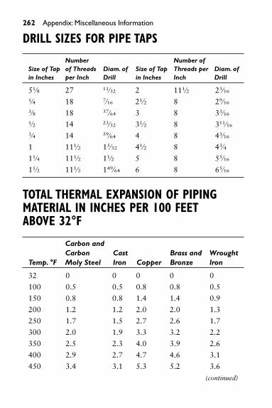
262 Appendix: Miscellaneous Information
DRILL SIZES FOR PIPE TAPS
Number Number of Size of Tap of Threads Diam. of Size of Tap Threads per Diam. of in Inches per Inch Drill in Inches Inch Drill
51⁄8 27 11⁄32 2 111⁄2 23⁄16
1⁄4 18 7⁄16 21⁄2 8 29⁄16
3⁄8 18 37⁄64 3 8 33⁄16
1⁄2 14 23⁄32 31⁄2 8 311⁄16
3⁄4 14 59⁄64 4 8 43⁄16
1 111⁄2 15⁄32 41⁄2 8 43⁄4
11⁄4 111⁄2 11⁄2 5 8 55⁄16
11⁄2 111⁄2 149⁄64 6 8 65⁄16
TOTAL THERMAL EXPANSION OF PIPINGMATERIAL IN INCHES PER 100 FEETABOVE 32°F
Carbon andCarbon Cast Brass and Wrought
Temp. °F Moly Steel Iron Copper Bronze Iron
32 0 0 0 0 0
100 0.5 0.5 0.8 0.8 0.5
150 0.8 0.8 1.4 1.4 0.9
200 1.2 1.2 2.0 2.0 1.3
250 1.7 1.5 2.7 2.6 1.7
300 2.0 1.9 3.3 3.2 2.2
350 2.5 2.3 4.0 3.9 2.6
400 2.9 2.7 4.7 4.6 3.1
450 3.4 3.1 5.3 5.2 3.6
(continued)

Appendix: Miscellaneous Information 263
Carbon andCarbon Cast Brass and Wrought
Temp. °F Moly Steel Iron Copper Bronze Iron
500 3.8 3.5 6.0 5.9 4.1550 4.3 3.9 6.7 6.5 4.6
600 4.8 4.4 7.4 7.2 5.2
650 5.3 4.8 8.2 7.9 5.6
700 5.9 5.3 9.0 8.5 6.1
750 6.4 5.8 - - 6.7
800 7.0 6.3 - - 7.2
850 7.4 - - - -
900 8.0 - - - -
950 8.5 - - - -
1000 9.1 - - - -
TYPICAL BTU VALUES OF FUELS
ASTM Rank Solids Btu Values per Pound
Anthracite Class I 11,230
Bituminous Class II Group 1 14,100
Bituminous Class II Group 3 13,080
Sub-Bituminous Class III Group 1 10,810
Sub-Bituminous Class III Group 2 9,670
Liquids Btu Values per Gallon
Fuel Oil No. 1 138,870
Fuel Oil No. 2 143,390
Fuel Oil No. 4 144,130
Fuel Oil No. 5 142,720
Fuel Oil No. 6 137,275
(continued)

264 Appendix: Miscellaneous Information
Gases Btu Values per Cubic Foot
Natural Gas 935 to 1132
Producers Gas 163
Illuminating Gas 534
Mixed (Coke oven and water gas) 545
PIPE HANGERS
Type Looks Like Type Looks Like
Band Hanger Wrought Short Clip
Adjustable Split “U” BoltRing Swivel Type
Adjustable Return Line
Ring “J” Hook

Type Looks Like Type Looks Like
Extension Split Adjustable Pipe Clamp Solid Ring
Swivel Type
Tin Clip Wrought Clevis
One Hole Roller HangerClamp
HEADS OF WATER IN FEET WITHEQUIVALENT PRESSURES
Pounds per Pounds per Feet Head Square Inch Feet Head Square Inch
1 0.43 100 43.31
2 0.87 110 47.64
3 1.30 120 51.97
4 1.73 130 56.30
5 2.17 140 60.63
6 2.60 150 64.96
7 3.03 160 69.29
(continued)
Appendix: Miscellaneous Information 265

266 Appendix: Miscellaneous Information
(continued)
Pounds per Pounds per Feet Head Square Inch Feet Head Square Inch
8 3.46 170 73.63
9 3.90 180 77.96
10 4.33 200 86.62
15 6.50 250 108.27
20 8.66 300 129.93
25 10.83 350 151.58
30 12.99 400 173.24
40 17.32 500 216.55
50 21.65 600 259.85
60 25.99 700 303.16
70 30.32 800 346.47
80 34.65 900 389.78
90 38.98 1000 433.00
Note: One foot of water at 62° Fahrenheit equals 0.433 pound pressure per squareinch.To find the pressure per square inch for any feet head not given in the table above,multiply the feet head by 0.433.
HEATING AND VENTILATING SYMBOLS
Item Symbol Item Symbol
High-Pressure Steam Supply Pipe
Low-Pressure Steam Supply Pipe
Radiator Trap(Elevation)
Radiator Trap (Plan)
(continued)

Appendix: Miscellaneous Information 267
Item Symbol Item Symbol
How Water Pipe-Flow (or Wet Return)
Return Pipe-Steam or Water (or Dry Return)
Air Vent Line
Flanges
Screwed Union
Elbow
Elbow LookingUp
Elbow LookingDown
Tee
Tee Looking Up
Expansion Joint
Air Supply Outlet
Exhaust Outlet
ColumnRadiator
(Plan)
ColumnRadiator
(Elevation)
ColumnRadiator
(End View)
Wall Radiator (Plan)
Wall Radiator(Elevation)
Wall Radiator (End View)
Pipe Coil (Plan)
(continued)

268 Appendix: Miscellaneous Information
(continued)
Item Symbol Item Symbol
Tee LookingDown
Gate Valve
Globe Valve
Angle Valve
Angle Valve(StemPerpendicular)
Lock ShieldValve
Check Valve
Reducing Valve
DiaphragmValve
Pipe Coil(Elevation)
Pipe Coil (EndView)
Indirect Radiator(Plan)
Indirect Radiator(Elevation)
Indirect Radiator (End View)
Supply Duct(Section)
Exhaust Duct(Section)
ButterflyDamper
(Plan orElevation)
ButterflyDamper
(Elevation orPlan)
(continued)

Appendix: Miscellaneous Information 269
(continued)
Item Symbol Item Symbol
DiaphragmValve (StemPerpendicular)
ThermostatT
DeflectingDamper(Square Pipe)
Vanes
HEAT LOSSES FROM HORIZONTAL BARESTEEL PIPE
The following is Btu per hour per linear foot at 70°F roomtemperature.
Nom. Pipe Size Hot Water (180�F) Steam 5 psig (20 psia)1⁄2 60 963⁄4 73 118
1 90 144
11⁄4 112 179
11⁄2 126 202
2 155 248
21⁄2 185 296
3 221 355
31⁄2 244 401
4 279 448

270 Appendix: Miscellaneous Information
CONVERSION TABLE (INCHES TOCENTIMETERS TO MILLIMETERS)
in cm mm
1.00 2.54 25.402.00 5.08 50.803.00 7.62 76.204.00 10.16 101.605.00 12.70 127.006.00 15.24 152.407.00 17.78 177.808.00 20.32 203.209.00 22.86 228.60
10.00 25.40 254.0020.00 50.80 508.0030.00 76.20 762.0036.00 91.40 914.0040.00 101.60 1016.0050.00 127.00 1270.0060.00 152.40 1524.0070.00 177.80 1778.0080.00 203.20 2032.0090.00 228.60 2286.00
100.00 254.00 2540.00
LAYING OUT ANGLES WITH A 6-FOOTFOLDING RULE
The following shows a 45° angle formed with a 6-ft foldingrule. To form this angle unfold the rule and place the tip on 23inches. The first two sections of the rule form a 45° angle. A6-foot folding rule is marked in 1⁄16-in increments; therefore,the numbers in the following chart are to the nearest 1⁄16 in.

Angle Set On
55⁄8 24 in111⁄4 2315⁄16 in221⁄2 233⁄4 in45 23 in60 221⁄4 in
SYMBOLS, WEIGHTS, AND MELTING POINTSOF METALS
MeltingWeight, in Weight, in Point,
Chemical Pounds per Pounds per DegreesMaterial Symbol Cubic Foot Cubic Inch Fahrenheit
Aluminum Al 0.093 160 1218Antimony Sb 0.2422 418 1150Brass 0.303 524 1800Bronze 0.320 552 1700Chromium Cr 0.2348 406 2740Copper Cu 0.323 450 2450Gold Au 0.6975 1205 1975Iron (cast) Fe 0.260 450 2450Iron (wrought) Fe 0.2834 490 2900Lead Pb 0.4105 710 620
(continued)
Appendix: Miscellaneous Information 271
12
11
10
98
76
54
32
1
2 42 32 22 12 01 91 81 71 61 51 43

272 Appendix: Miscellaneous Information
(continued)Melting
Weight, in Weight, in Point,Chemical Pounds per Pounds per Degrees
Material Symbol Cubic Foot Cubic Inch Fahrenheit
Manganese Mn 0.2679 463 2200
Mercury Hg 0.491 849 –39.5Molybdenum Mo 0.309 534 4500Monel 0.318 550 2480Platinum Pt 0.818 1413 3200Steel (mild) Fe 0.2816 490 2600Steel (stainless) 0.277 484 2750Tin Sn 0.265 459 450Titanium Ti 0.1278 221 3360Zinc Zn 0.258 446 787
CONVERSION TABLE (METRIC TO ENGLISH)
Metric English
Measures of Length
1 kilometer 0.621 mile1000 meters 3281. feet
1 meter 1.094 yards100 centimeters 3.28 feet1000 millimeters 39.37 inches
1 centimeter 0.0328 feet10 millimeters 0.394 inches
1 millimeter 0.0394 inches
Measures of Surface
1 square kilometer 0.386 square mile1,000,000 square meter 247.1 acres
1,195,985 square yards(continues)

1 square meter 1.196 square yards
10,000 square centimeters 10.76 square feet
1550. square inches
1 square centimeter 0.155 square inch
100 square millimeters 0.0011 square feet
1 square millimeter 0.00155 square inch
Measures of Volume and Capacity
1 cubic meter 1.308 cubic yards
1000 liters 35.31 cubic feet
1,000,000 cubic centimeters 61023.4 cubic inches
1 liter 0.264 gallons (u.s.)
1000 cubic centimeters 0.220 gallons (imperial)
1.057 quarts (u.s.)
0.880 quarts (imperial)
1 cubic centimeter 0.061 cubic inches
1000 cubic millimeters
Measures of Weight
1 kilogram 0.0011 ton (2000 lbs)
1000 gram 2.205 pounds (av)
1 gram 0.0022 pounds (av)
0.035 ounces (av)
15.43 grains
MULTIPLIERS THAT ARE USEFUL TO THE TRADE
To Change To Multiply by
Inches Feet 0.0833Inches Millimeters 25.4Feet Inches 12.Feet Yards 3.
(continued)
Appendix: Miscellaneous Information 273

274 Appendix: Miscellaneous Information
(continued)
To Change To Multiply by
Yards Feet 0.03333Square inches Square feet 0.00694Square feet Square inches 144.Square feet Square yards 0.11111
Square yards Square feet 9.
Cubic inches Cubic feet 0.00058
Cubic feet Cubic inches 1728.
Cubic feet Cubic yards 0.03703
Cubic yards Cubic feet 27.
Cubic inches Gallons 0.00433
Cubic feet Gallons 7.48
Gallons Cubic inches 231.
Gallons Cubic feet 0.1337
Gallons Pounds of water 8.33
Pounds of water Gallons 0.12004
Ounces Pounds 0.0625
Pounds Ounces 16.
Inches of water Lbs. per sq. inch 0.0361
Inches of water Inches of mercury 0.0735
Inches of water Ounces per sq. inch 0.578
Inches of water Lbs. per sq. foot 5.2
Inches of mercury Inches of water 13.6
Inches of mercury Feet of water 1.1333
Inches of mercury Lbs. per sq. inch 0.4914
Ounces per sq. inch Inches of mercury 0.127
Ounces per sq. inch Inches of water 1.733
Pounds per sq. inch Inches of water 27.72
Pounds per sq. inch Feet of water 2.310
(continued)

(continued)
To Change To Multiply by
Pounds per sq. inch Inches of mercury 2.04Pounds per sq. inch Atmospheres 0.0681Feet of water Lbs. per sq. inch 0.434Feet of water Lbs. per sq. foot 62.5Feet of water Inches of mercury 0.8824Atmospheres Lbs. per sq. inch 14.696Atmospheres Inches of mercury 29.92Atmospheres Feet of water 34.Long tons Pounds 2240.Short tons Pounds 2000.Short tons Long tons 0.89285
EXPANSION OF PIPES IN INCHES PER 100 FEET
Cast Wrought Brass or Temperature �F Iron Iron Steel Copper
0 0.00 0.00 0.00 0.0050 0.36 0.40 0.38 0.57
100 0.72 0.79 0.76 1.14125 0.88 0.97 0.92 1.40150 1.10 1.21 1.15 1.75175 1.28 1.41 1.34 2.04200 1.50 1.65 1.57 2.38225 1.70 1.87 1.78 2.70250 1.90 2.09 1.99 3.02275 2.15 2.36 2.26 3.42300 2.35 2.58 2.47 3.74325 2.60 2.86 2.73 4.13350 2.80 3.08 2.94 4.45
Appendix: Miscellaneous Information 275

PROPERTIES OF SATURATED STEAM(APPROX.)
Gage Heat in Latent Heat Volume of Weight ofReading Water in Steam 1 Pound Water
Absolute at Sea Temp. Btu per (Vaporization) Steam Pounds perPressure Level �F. Pound Btu per Pound Cubic Feet Cubic Feet
0.18 29.7 32 0.0 1076 3306 62.4
0.50 29.4 59 27.0 1061 1248 62.3
1.0 28.9 79 47.0 1049 653 62.2
2.0 28 101 69 1037 341 62.0
4.0 26 125 93 1023 179 61.7
6.0 24 141 109 1014 120 61.4
8.0 22 152 120 1007 93 61.1
10.0 20 161 129 1002 75 60.9
12.0 18 169 137 997 63 60.8
14.0 16 176 144 993 55 60.6
16.0 14 182 150 989 48 60.5
18.0 12 187 155 986 43 60.4
20.0 10 192 160 983 39 60.3
22.0 8 197 165 980 36 60.2
24.0 6 201 169 977 33 60.1
26.0 4 205 173 975 31 60.0
28.0 2 209 177 972 29 59.9
29.0 1 210 178 971 28 59.9
30.0 0 212 180 970 27 59.8
14.7 0 212 180 970 27 59.8
15.7 1 216 184 968 25 59.8
16.7 2 219 187 966 24 59.7
17.7 3 222 190 964 22 59.6
(continued)
PRE
SSU
RE
PO
UN
DS
PER
SQ
UA
RE
IN
CH
276 Appendix: Miscellaneous Information
POU
ND
S PE
R S
QU
AR
E I
NC
H

INC
HE
S O
F M
ER
CU
RY
(continued)
Gage Heat in Latent Heat Volume of Weight ofReading Water in Steam 1 Pound Water
Absolute at Sea Temp. Btu per (Vaporization) Steam Pounds perPressure Level �F. Pound Btu per Pound Cubic Feet Cubic Feet
18.7 4 225 193 962 21 59.519.7 5 227 195 960 20 59.4
20.7 6 230 198 958 19 59.4
21.7 7 232 200 957 19 59.3
22.7 8 235 203 955 18 59.2
23.7 9 237 205 954 17 59.2
25 10 240 208 952 16 59.2
30 15 250 219 945 14 58.8
35 20 259 228 939 12 58.5
40 25 267 236 934 10 58.3
45 30 274 243 929 9 58.1
50 35 281 250 924 8 57.9
55 40 287 256 920 8 57.7
60 45 293 262 915 7 57.5
65 50 298 268 912 7 57.4
70 55 303 273 908 6 57.2
75 60 308 277 905 6 57.0
85 70 316 286 898 5 56.8
95 80 324 294 892 5 56.5
105 90 332 302 886 4 56.3
115 100 338 309 881 4 56.0
140 125 353 325 868 3 55.5
VA
CU
UM
IN
CH
ES
OF
ME
RC
UR
Y
Appendix: Miscellaneous Information 277
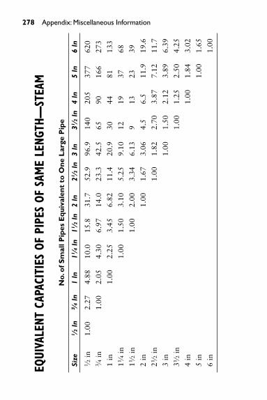
278 Appendix: Miscellaneous Information
EQUI
VALE
NT C
APAC
ITIE
S OF
PIP
ES O
F SA
ME
LENG
TH—
STEA
M
No.
of S
mal
l Pip
es E
quiv
alen
t to
One
Lar
ge P
ipe
Size
1⁄2
In3⁄4
In1
In11
⁄4In
11⁄2
In2
In21
⁄2In
3 In
31⁄2
In4
In5
In6
In1⁄2
in1.
002.
274.
8810
.015
.831
.752
.996
.914
020
537
762
03⁄4
in1.
002.
054.
306.
9714
.023
.342
.565
9016
627
3
1 in
1.00
2.25
3.45
6.82
11.4
20.9
3044
8113
3
11⁄4
in1.
001.
503.
105.
259.
1012
1937
68
11⁄2
in1.
002.
003.
346.
139
1323
39
2 in
1.00
1.67
3.06
4.5
6.5
11.9
19.6
21⁄2
in1.
001.
822.
703.
877.
1211
.7
3 in
1.00
1.50
2.12
3.89
6.39
31⁄2
in1.
001.
252.
504.
25
4 in
1.00
1.84
3.02
5 in
1.00
1.65
6 in
1.00
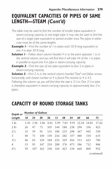
EQUIVALENT CAPACITIES OF PIPES OF SAMELENGTH—STEAM (Cont’d)
This table may be used to find the number of smaller pipes equivalent insteam-carrying capacity to one larger pipe. It may also be used to find thesize of a larger pipe equivalent to several smaller ones.The pipes in eithercase must be of the same lengths.
Example 1—Find the number of 1-in pipes each 50 ft long equivalent toone 4-in pipe 50 ft long.
Solution 1—Follow down column headed 4 in to the point opposite 1 in, inthe vertical column, and you will find that it will take 44 of the 1-in pipesin parallel to equal one 4-in pipe in steam-carrying capacity.
Example 2—Find the size of one pipe equivalent to four 2-in pipes insteam-carrying capacity.
Solution 2—Find 2 in, in the vertical column headed "Size" and follow acrosshorizontally until closest number to 4 is found.The nearest to 4 is 4.5.Following this column up, you will find that the size is 31⁄2-in. One 31⁄2-in pipeis, therefore, equivalent in steam-carrying capacity to approximately four 2-inpipes.
CAPACITY OF ROUND STORAGE TANKS
Depth or Number of Gallons
Length 18 24 30 36 12 48 54 60 66 72
1 In 1.10 1.96 3.06 4.41 5.99 7.83 9.91 12.24 14.81 17.62
2 Ft 26 47 73 105 144 188 238 294 356 423
21⁄2 33 59 91 131 180 235 298 367 445 530
3 40 71 100 158 216 282 357 440 534 635
31⁄2 46 83 129 184 252 329 416 513 623 740
4 53 95 147 210 288 376 475 586 712 846
41⁄2 59 107 165 238 324 423 534 660 800 952
(continued)
Appendix: Miscellaneous Information 279

280 Appendix: Miscellaneous Information
(continued)
Depth or Number of Gallons
Length 18 24 30 36 12 48 54 60 66 72
5 66 119 181 264 360 470 596 734 899 1057
51⁄2 73 130 201 290 396 517 655 808 979 1163
6 79 141 219 315 432 564 714 880 1066 1268
61⁄2 88 155 236 340 468 611 770 954 1156 1374
7 92 165 255 368 504 658 832 1028 1244 1480
71⁄2 99 179 278 396 540 705 889 1101 1335 1586
8 106 190 291 423 576 752 949 1175 1424 1691
9 119 212 330 476 648 846 1071 1322 1599 1903
10 132 236 366 529 720 940 1189 1463 1780 2114
12 157 282 440 634 684 1128 1428 1762 2133 2537
14 185 329 514 740 1008 1316 1666 2056 2490 2960
16 211 376 587 846 1152 1504 1904 2350 2844 3383
18 238 423 660 952 1296 1692 2140 2640 3200 3806
20 264 470 734 1057 1440 1880 2380 2932 3556 4230
Rectangular Tank: To find the capacity in U.S. gallons of rectangular tanks, reduce all dimensions to inches,then multiply the length by the width by the height and divide the product by 231.Example: A tank is 56 in long � 32 in wide � 20 in deepThen 56 in � 32 in � 20 in = 35840 cu in35840 � 231 = 155 gal capacity
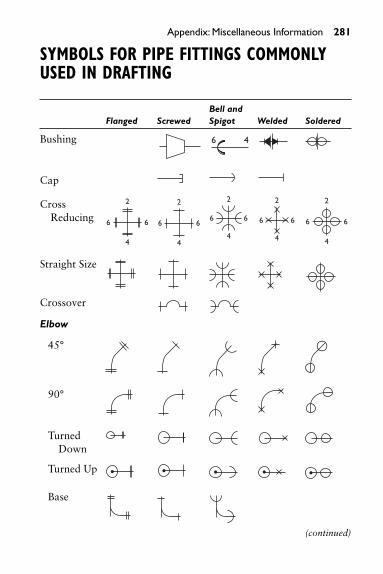
Appendix: Miscellaneous Information 281
SYMBOLS FOR PIPE FITTINGS COMMONLYUSED IN DRAFTING
Bell and Flanged Screwed Spigot Welded Soldered
Bushing
Cap
Cross Reducing
Straight Size
Crossover
Elbow
45°
90°
Turned Down
Turned Up
Base
2
6 6
4
2
6 6
44
2
6 6
6 4
4
2
6 6
4
2
6 6
(continued)

(continued)
Bell and Flanged Screwed Spigot Welded Soldered
Double Branch
Long Radius
Reducing
Side Outlet (OutletDown)
Side Outlet (Outlet Up)
Street
Joint
ConnectingPipe
Expansion
Lateral
Office Plate
Reducing Flange
LR LR
2
4
2
4
2
4
2
4
282 Appendix: Miscellaneous Information

Appendix: Miscellaneous Information 283
(continued)
Bell and Flanged Screwed Spigot Welded Soldered
Plugs
Bull Plug
Pipe Plug
Reducer
Concentric
Eccentric
Sleeve
Tee
Straight Size
(Outlet Up)
(Outlet Down)
Double Sweep
Reducing 2
46
2
46
2
46
2
46
2
46
(continued)

284 Appendix: Miscellaneous Information
(continued)
Bell and Flanged Screwed Spigot Welded Soldered
Single Sweep
Side Outlet (OutletDown)
Side Outlet (Outlet Up)
Union
Angle Valve
Check (AlsoAngle Check)
Gate (Also Angle Gate) (Elevation)
Gate (Also Angle Gate) (Plan)

Appendix: Miscellaneous Information 285
(continued)
Bell and Flanged Screwed Spigot Welded Soldered
Globe (Also Angle Globe) (Elevation)
Globe (Plan)
Automatic Valve
By-Pass
Governor-Operated
Reducing
Check Valve(Straight
Way)
Cock
Diaphragm Valve
(continued)

286 Appendix: Miscellaneous Information
(continued)
Bell and Flanged Screwed Spigot Welded Soldered
Float Valve
Gate Valve*
Motor-Operated
Globe Valve
Hose Valve(Also Hose Globe);Angle (Also HoseAngle)
Gate
Globe
Lockshield Valve
Quick Opening Valve
Safety Valve
*Also used for General Stop Valve symbol when amplified by specification.Symbols (courtesy of Mechanical Contractors Association of America, Inc.)
M MM
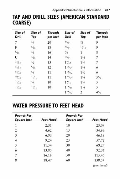
Appendix: Miscellaneous Information 287
TAP AND DRILL SIZES (AMERICAN STANDARDCOARSE)
Size of Size of Threads Size of Size of ThreadsDrill Tap per Inch Drill Tap per Inch
7 1⁄4 20 49⁄64 7⁄8 9
F 5⁄16 18 53⁄64 15⁄16 95⁄16 3⁄8 16 7⁄8 1 8
U 7⁄16 14 63⁄64 11⁄8 727⁄64 1⁄2 13 17⁄64 11⁄4 731⁄64 9⁄16 12 113⁄64 13⁄8 617⁄32 5⁄8 11 111⁄32 11⁄2 619⁄32 11⁄16 11 129⁄64 15⁄8 51⁄221⁄32 3⁄4 10 19⁄16 13⁄4 523⁄32 13⁄16 10 111⁄16 17⁄8 5
125⁄32 2 41⁄2
WATER PRESSURE TO FEET HEAD
Pounds Per Pounds Per Square Inch Feet Head Square Inch Feet Head
1 2.31 10 23.09
2 4.62 15 34.63
3 6.93 20 46.18
4 9.24 25 57.72
5 11.54 30 69.27
6 13.85 40 92.36
7 16.16 50 115.45
8 18.47 60 138.54
(continued)

288 Appendix: Miscellaneous Information
(continued)
Pounds Per Pounds Per Square Inch Feet Head Square Inch Feet Head
9 20.78 70 161.63
80 184.72 200 461.78
90 207.81 250 577.24
100 230.90 300 692.69
110 253.98 350 808.13
120 277.07 400 922.58
130 300.16 500 1154.48
140 323.25 600 1385.39
150 346.34 700 1616.30
160 369.43 800 1847.20
170 392.52 900 2078.10
180 415.61 1000 2309.00
Note: One pound of pressure per square inch of water equals 2.31 feet of water at 62�
Fahrenheit.Therefore, to find the feet head of water for any pressure not given in the tableabove, multiply the pressure pounds per square inch by 2.31.
FEET HEAD OF WATER TO PSI
Pounds Per Pounds PerFeet Head Square Inch Feet Head Square Inch
1 0.43 100 43.31
2 0.87 110 47.64
3 1.30 120 51.97
4 1.73 130 56.30
5 2.17 140 60.63
6 2.60 150 64.96
7 3.03 160 69.29
(continued)

Appendix: Miscellaneous Information 289
(continued)
Pounds Per Pounds PerFeet Head Square Inch Feet Head Square Inch
8 3.46 170 73.63
9 3.90 180 77.96
10 4.33 200 86.62
15 6.50 250 108.27
20 8.66 300 129.93
25 10.83 350 151.58
30 12.99 400 173.24
40 17.32 500 216.55
50 21.65 600 259.85
60 25.99 700 303.16
70 30.32 800 346.47
80 34.65 900 389.78
90 38.98 1000 433.00
Note: One foot of water at 62� Fahrenheit equals .434 pounds pressure per square inch.To find the pressure per square inch for any feet head not given in the table above,multiply the feet head by .434.

290 Appendix: Miscellaneous InformationPR
OPER
TIES
OF
WAT
ER A
T VA
RIOU
S TE
MPE
RATU
RES
Pre
ssur
eK
inem
atic
of S
atur
ated
Den
sity
Con
vers
ion
Visc
osit
yTe
mp
erat
ure
Vap
orSp
ecif
ic V
olum
eSp
ecif
ic W
eigh
tFa
ctor
Cen
tist
okes
�F�C
lb/in
2ab
sft
3 /lb
gal/l
blb
/ft3
g/cm
3 aft
/lb/in
2
320
0.06
859
0.01
6022
0.11
9962
.414
0.99
962.
307
1.79
330.
60.
0922
30.
0160
210.
1196
62.4
180.
9999
2.30
71.
75
341.
10.
0960
00.
0160
210.
1196
62.4
180.
9999
2.30
71.
72
351.
70.
0999
10.
0160
200.
1196
62.4
200.
9999
2.30
71.
68
362.
20.
1039
50.
0160
200.
1196
62.4
200.
9999
2.30
71.
66
372.
80.
1061
50.
0160
200.
1196
62.4
200.
9999
2.30
71.
63
383.
30.
1124
90.
0160
190.
1196
62.4
251.
0000
2.30
71.
60
393.
90.
1169
60.
0160
190.
1196
62.4
251.
0000
2.30
71.
56
404.
40.
1216
30.
0160
190.
1196
62.4
251.
0000
2.30
71.
54
415
0.12
645
0.01
6019
0.11
9662
.426
1.00
002.
307
1.52
425.
60.
1314
30.
0160
190.
1196
62.4
261.
0000
2.30
71.
49
436.
10.
1365
90.
0160
190.
1196
62.4
261.
0000
2.30
71.
47
446.
70.
1419
20.
0160
190.
1196
62.4
261.
0000
2.30
71.
44 (con
tinu
ed)

Appendix: Miscellaneous Information 29145
7.2
0.14
744
0.01
6020
0.11
9662
.42
0.99
992.
307
1.42
467.
80.
1531
40.
0160
200.
1196
62.4
20.
9999
2.30
71.
39
478.
30.
1590
40.
0160
210.
1196
62.4
20.
9999
2.30
71.
37
488.
90.
1651
40.
0160
210.
1196
62.4
20.
9999
2.30
71.
35
499.
40.
1714
40.
0160
220.
1196
62.4
10.
9996
2.30
71.
33
5010
0.17
796
0.01
6023
0.11
9962
.41
0.99
962.
307
1.31
5110
.60.
1846
90.
0160
230.
1199
62.4
10.
9996
2.30
71.
28
5211
.10.
1916
50.
0160
240.
1199
62.4
10.
9997
2.30
71.
26
5311
.70.
1988
30.
0160
250.
1199
62.4
00.
9996
2.30
81.
24
5412
.20.
2062
50.
0160
260.
1199
62.4
00.
9996
2.30
81.
22
5512
.80.
2139
20.
0160
270.
1199
62.3
90.
9995
2.30
81.
20
5613
.30.
2218
30.
0160
280.
1199
62.3
90.
9994
2.30
81.
19
5713
.90.
2300
00.
0160
290.
1199
62.3
90.
9994
2.30
81.
17
5814
.40.
2384
30.
0160
310.
1199
62.3
80.
9993
2.30
81.
16
5915
0.24
713
0.01
6032
0.11
9962
.38
0.99
922.
309
1.14
6015
.60.
2561
10.
0160
330.
1199
62.3
70.
9991
2.30
91.
12
6216
.70.
2749
40.
0160
360.
1200
62.3
60.
9989
2.30
91.
09
6417
.80.
2949
70.
0160
390.
1200
62.3
50.
9988
2.31
01.
06
6618
.90.
3162
60.
0160
430.
1200
62.3
30.
9985
2.31
01.
03
6820
0.33
889
0.01
6046
0.12
0062
.32
0.99
832.
311
1.00 (c
onti
nued
)

292 Appendix: Miscellaneous Information(c
onti
nued
)
Pre
ssur
eK
inem
atic
of S
atur
ated
Den
sity
Con
vers
ion
Visc
osit
yTe
mp
erat
ure
Vap
orSp
ecif
ic V
olum
eSp
ecif
ic W
eigh
tFa
ctor
Cen
tist
okes
�F�C
lb/in
2ab
sft
3 /lb
gal/l
blb
/ft3
g/cm
3 aft
/lb/in
2
7021
.10.
3629
20.
0160
500.
1201
62.3
10.
9961
2.31
10.
98
7523
.90.
4296
40.
0160
600.
1201
62.2
70.
9974
2.31
30.
90
8026
.70.
5068
30.
0160
720.
1202
62.2
20.
9967
2.31
40.
85
8529
.40.
5958
30.
0160
850.
1203
62.1
70.
9959
2.31
60.
81
9032
.20.
6961
30.
0160
990.
1204
62.1
20.
9950
2.31
80.
76
9535
0.81
534
0.01
6144
0.12
0562
.06
0.99
412.
320
0.72
100
37.8
0.94
924
0.01
6130
0.12
0762
.00
0.99
312.
323
0.69
110
43.3
1.27
500.
0161
650.
1209
61.9
60.
9910
2.32
60.
61
120
48.9
1.69
270.
0162
040.
1212
61.7
10.
9666
2.33
30.
57
130
54.4
2.22
300.
0162
470.
1215
61.5
60.
9660
2.34
00.
51
140
602.
8892
0.01
6293
0.12
1961
.38
0.98
322.
346
0.47
150
65.6
3.71
840.
0163
430.
1223
61.1
90.
9802
2.35
30.
44
160
71.1
4.74
140.
0163
950.
1226
60.9
90.
9771
2.36
10.
41
170
76.7
5.99
260.
0164
510.
1231
60.7
90.
9737
2.36
90.
36
180
82.2
7.51
100.
0165
100.
1235
60.5
70.
9703
2.37
70.
36

Appendix: Miscellaneous Information 29319
087
.89.
340
0.01
6572
0.12
4060
.34
0.96
662.
3861
0.33
200
93.3
11.5
260.
0166
370.
1245
60.1
10.
9628
2.39
60.
31
210
98.9
14.1
230.
0167
050.
1250
59.8
60.
9589
2.40
60.
29
212
100.
014
.696
0.01
6719
0.12
5159
.81
0.95
80
220
104.
417
.186
0.01
6775
0.12
5559
.61
0.95
492.
416
230
110.
20.7
790.
0168
490.
1260
59.3
50.
9507
2.42
6
240
115.
624
.968
0.01
6926
0.12
6659
.08
0.94
642.
437
250
121.
129
.825
0.01
7006
0.12
7258
.80
0.94
202.
449
0.24
260
126.
735
.427
0.01
7089
0.12
7858
.52
0.93
742.
461
270
132.
241
.856
0.01
7175
0.12
8558
.22
0.93
272.
473
280
137.
849
.200
0.01
7264
0.12
9157
.92
0.92
792.
486
290
143.
357
.550
0.01
736
0.12
9957
.60
0.92
282.
500
300
148.
967
.005
0.01
745
0.13
0557
.31
0.91
802.
513
0.20
310
154.
477
.667
0.01
755
0.13
1356
.98
0.91
282.
527
320
160
89.6
430.
0176
60.
1321
56.6
30.
9071
2.54
3
330
165.
610
3.04
50.
0177
60.
1329
56.3
10.
9020
2.55
7
340
171.
111
7.99
20.
0178
70.
1337
55.9
60.
8964
2.57
3
350
176.
713
4.60
40.
0179
90.
1346
55.5
90.
8904
2.59
10.
17
360
182.
215
3.01
00.
0181
10.
1355
55.2
20.
8845
2.60
8
(con
tinu
ed)

294 Appendix: Miscellaneous Information(c
onti
nued
)
Pre
ssur
eK
inem
atic
of S
atur
ated
Den
sity
Con
vers
ion
Visc
osit
yTe
mp
erat
ure
Vap
orSp
ecif
ic V
olum
eSp
ecif
ic W
eigh
tFa
ctor
Cen
tist
okes
�F�C
lb/in
2ab
sft
3 /lb
gal/l
blb
/ft3
g/cm
3 aft
/lb/in
2
370
187.
817
3.33
90.
0182
30.
1364
54.8
40.
8787
2.62
5
380
193.
319
5.72
90.
0183
60.
1374
54.4
70.
8725
2.64
4
390
198.
922
0.32
10.
0185
00.
1384
54.0
50.
8659
2.66
4
400
204.
424
7.25
90.
0186
40.
1394
53.6
50.
8594
2.68
40.
15
410
392.
227
6.69
40.
0187
80.
1404
53.2
50.
8530
2.70
4
420
215.
630
6.78
00.
0189
40.
1417
52.8
00.
8458
2.72
7
430
221.
134
3.67
40.
0190
90.
1426
52.3
80.
8391
2.74
9
440
226.
738
1.54
0.01
926
0.14
4151
.92
0.83
172.
773
450
232.
242
2.55
0.01
943
0.14
5351
.47
0.82
442.
796
0.14
460
237.
846
6.87
0.01
961
0.14
6750
.99
0.81
692.
824
470
243.
351
4.67
0.01
960
0.14
8150
.51
0.80
902.
851
480
248.
956
6.15
0.02
000
0.14
9650
.00
0.80
102.
880
490
254.
462
1.48
0.02
021
0.15
1249
.48
0.79
262.
910
500
260
680.
860.
0204
30.
1528
48.9
50.
7841
2.94
20.
13
510
265.
674
4.47
0.02
067
0.15
4648
.38
0.77
502.
976

Appendix: Miscellaneous Information 29552
027
1.1
812.
530.
0209
10.
1564
47.8
20.
7661
3.01
1
530
276.
788
5.23
0.02
118
0.15
8447
.21
0.75
633.
050
540
282.
296
2.79
0.02
146
0.16
0546
.60
0.74
853.
090
550
287.
810
45.4
30.
0217
60.
1628
45.9
60.
7362
3.13
30.
12
560
293.
311
33.3
80.
0220
70.
1651
45.3
10.
7258
3.17
8
570
298.
912
26.8
80.
0224
20.
1677
44.6
00.
7145
3.22
8
580
304.
413
26.1
70.
0227
90.
1705
43.8
60.
7029
3.28
1
590
310
1431
.50.
0231
90.
1735
43.1
20.
6906
3.33
9
600
315.
615
43.2
0.02
364
0.17
6842
.30
0.67
763.
404
0.12
610
321.
116
61.6
0.02
412
0.18
0441
.46
0.66
413.
473
620
326.
617
86.9
0.02
466
0.18
4540
.55
0.64
963.
551
630
332.
219
19.5
0.02
526
0.18
9039
.59
0.63
423.
637
640
337.
820
59.9
0.02
595
0.19
4136
.54
0.61
733.
737
650
343.
322
03.4
0.02
674
0.20
0037
.40
0.59
913.
851
670
354.
425
32.2
0.02
884
0.21
5734
.67
0.55
544.
153
690
365.
628
95.7
0.03
256
0.24
3630
.71
0.49
204.
689
700
371.
130
94.3
0.03
662
0.27
3927
.31
0.43
745.
273
705.
4737
4.15
3206
.20.
0507
80.
3799
19.6
90.
3155
7.31
2
(a ) A
ppro
xim
atel
y nu
mer
ically
equ
al to
spe
cific
grav
ity b
asis
tem
per a
ture
refe
renc
e of
39.
2 �F
(4�C
).(C
ourt
esy
Schl
umbe
rger
Indu
strie
s,In
c).

296 Appendix: Miscellaneous Information
RELA
TION
S OF
ALT
ITUD
E,PR
ESSU
RE, A
ND B
OILI
NG P
OINT
Atm
osp
heri
c P
ress
ure
Abs
olut
eB
oilin
g P
oint
of W
ater
�F
(Bas
e P
ress
ure
psi
)
Alt
itud
e In
ches
of
Mer
cury
Pou
nds
per
Feet
(Bar
omet
er)
Squa
re In
ch0
15
1015
–500
30.4
614
.96
212.
821
6.1
227.
723
9.9
250.
2
–100
30.0
114
.74
212.
321
5.5
227.
223
9.4
249.
9
Sea
Lev
el29
.90
14.6
921
2.0
215.
322
7.0
239.
324
9.7
500
29.3
514
.42
211.
021
4.4
226.
323
8.7
249.
2
1000
28.8
214
.16
210.
121
3.5
225.
523
8.1
248.
6
1500
28.3
013
.90
209.
421
2.7
225.
023
7.6
248.
2
2000
27.7
813
.65
208.
221
1.7
224.
123
6.8
247.
7
2500
27.2
713
.40
207.
321
0.9
223.
423
6.3
247.
2
3000
26.7
713
.15
206.
421
0.1
222.
723
5.7
246.
7
3500
26.2
912
.91
205.
520
9.2
222.
123
5.1
246.
2
4000
25.8
112
.68
204.
720
8.4
221.
423
4.6
245.
7

4500
25.3
412
.45
203.
720
7.5
220.
723
4.0
245.
2
5000
24.8
812
.22
202.
720
6.8
220.
123
3.4
244.
7
6000
23.9
811
.78
200.
920
5.0
218.
723
2.4
243.
8
7000
23.1
111
.35
199.
120
3.3
217.
323
1.3
242.
9
8000
22.2
810
.94
197.
420
1.6
216.
123
0.3
242.
0
9000
21.4
710
.55
195.
720
0.0
214.
822
9.3
241.
3
1000
020
.70
10.1
719
4.0
198.
421
3.5
228.
324
0.4
1100
019
.95
9.80
192.
219
6.8
212.
322
7.3
239.
6
1200
019
.23
9.45
190.
619
5.2
211.
122
6.3
238.
7
1300
018
.53
9.10
188.
719
3.6
209.
922
5.4
237.
9
1400
017
.86
8.77
187.
219
2.3
208.
822
4.5
237.
2
1500
017
.22
8.46
185.
419
0.6
207.
622
3.6
236.
4
Appendix: Miscellaneous Information 297

298 Appendix: Miscellaneous Information
WATER REQUIRED FOR HUMIDIFICATION
The approximate rule for calculating the amount of waterrequired per hour to maintain any desired humidity in aroom is: Multiply the difference between the number ofgrains of moisture per cubic foot of air at the required roomtemperature and humidity and the number of grains percubic foot of outside air at the given temperature and humid-ity by the cubic contents of the room by the number of airchanges per hour and divide the result by 7000 (this methoddisregards the expansion of air when heated.)
For most localities, it is customary to assume that theaverage humidity of outside air is 30 to 40 percent.
Example:
Grains of moisture at 70� & 40 percent humidity � 3.19Grains of moisture at 0� & 30 percent humidty � 0.17Grains of moisture to be added per ft3 � 3.02
Assuming two air changes per hour in a room con-taining 8000 ft3 we have
� 6.9 lb of water per hour required.(3.02 � 8000 � 2)
7000

WEI
GHT
OF W
ATER
PER
CUB
IC F
OOT
AND
HEAT
UNI
TS IN
WAT
ERBE
TWEE
N 32
�AN
D 21
2�F
Wei
ght
Wei
ght
Wei
ght
in p
ound
sH
eat
in p
ound
s H
eat
in p
ound
sH
eat
Tem
pera
ture
per
Cub
icU
nits
Tem
pera
ture
per
Cub
ic
Uni
tsTe
mpe
ratu
rep
er C
ubic
Uni
ts�F
foot
(Btu
)�F
Foot
(Btu
)�F
Foot
(Btu
)
3262
.42
0.00
9462
.09
62.0
215
461
.10
121.
88
3462
.42
2.01
9662
.07
64.0
115
661
.06
123.
88
3662
.42
4.03
9862
.05
66.0
115
861
.02
125.
88
3862
.42
6.04
100
62.0
268
.00
160
60.9
812
7.88
4062
.42
8.05
102
62.0
069
.99
162
60.9
412
9.87
4262
.42
10.0
610
461
.97
71.9
916
460
.90
131.
87
4462
.42
12.0
710
661
.95
73.9
916
660
.85
133.
88
4662
.42
14.0
710
861
.92
75.9
716
860
.81
135.
88
4862
.41
16.0
711
061
.89
77.9
717
060
.77
137.
88
5062
.41
18.0
811
261
.86
79.9
617
260
.73
139.
88
5262
.40
20.0
811
461
.83
81.9
617
460
.68
141.
88
5462
.40
22.0
811
661
.80
83.9
517
660
.64
143.
89
(con
tinu
ed)

(con
tinu
ed)
Wei
ght
Wei
ght
Wei
ght
in p
ound
sH
eat
in p
ound
s H
eat
in p
ound
sH
eat
Tem
pera
ture
per
Cub
icU
nits
Tem
pera
ture
per
Cub
ic
Uni
tsTe
mpe
ratu
rep
er C
ubic
Uni
ts�F
foot
(Btu
)�F
Foot
(Btu
)�F
Foot
(Btu
)
5662
.39
24.0
811
861
.77
85.9
417
860
.59
145.
89
5862
.38
26.0
812
061
.74
87.9
418
060
.55
147.
89
6062
.37
28.0
812
261
.70
89.9
318
260
.50
149.
89
6262
.36
30.0
812
461
.67
91.9
318
460
.46
151.
90
6462
.35
32.0
812
661
.63
93.9
218
660
.41
153.
90
6662
.34
34.0
812
861
.60
95.9
218
860
.37
155.
91
6862
.33
36.0
813
061
.56
97.9
119
060
.32
157.
91
7062
.31
38.0
813
261
.52
99.9
119
260
.27
159.
92
7262
.30
40.0
713
461
.49
101.
9019
460
.22
161.
92
7462
.28
42.0
713
661
.45
103.
9019
660
.17
163.
93
7662
.27
44.0
613
861
.41
105.
9019
860
.12
165.
94

7862
.25
46.0
614
061
.37
107.
8920
060
.07
167.
95
8062
.23
48.0
514
261
.34
109.
8920
260
.02
169.
95
8262
.21
50.0
514
461
.30
111.
8920
459
.97
171.
96
8462
.19
52.0
414
661
.26
113.
8920
659
.92
173.
97
8662
.17
54.0
414
861
.22
115.
8820
859
.87
175.
98
8862
.15
56.0
315
061
.18
117.
8821
059
.82
177.
99
9062
.13
58.0
315
261
.14
119.
8821
259
.76
180.
00
9262
.11
60.0
2
Wei
ghts
from
Tra
ns.A
.S.M
.E.,V
ol.6
Hea
t Uni
ts fr
om G
oode
noug
h’s
Stea
m T
able
s(1
917)
.

302 Appendix: Miscellaneous InformationNA
TURA
L TR
IGON
OMET
RIC
FUNC
TION
S
Deg
s.Si
neC
osin
eTa
ngen
tSe
cant
Deg
rees
Sine
C
osin
eTa
ngen
tSe
cant
00.
0000
01.
0000
0.00
000
1.00
0046
0.71
930.
6947
1.03
551.
4395
10.
0174
50.
9998
0.01
745
1.00
0147
0.73
140.
6820
1.07
241.
4663
20.
0349
00.
9994
0.03
492
1.00
0648
0.74
310.
6691
1.11
061.
4945
30.
0523
40.
9986
0.05
241
1.00
1449
0.75
470.
6561
1.15
041.
5242
40.
0697
60.
9976
0.06
993
1.00
2450
0.76
600.
6428
1.19
181.
5557
50.
0871
60.
9962
0.08
749
1.00
3851
0.77
710.
6293
1.23
491.
5890
60.
1045
30.
9945
0.10
510
1.00
5552
0.78
800.
6157
1.27
991.
6243
70.
1218
70.
9925
0.12
278
1.00
7553
0.79
860.
6018
1.32
701.
6616
80.
1392
0.99
030.
1405
1.00
9854
0.80
900.
5878
1.37
641.
7013
90.
1564
0.98
770.
1584
1.01
2555
0.81
920.
5736
1.42
811.
7434
100.
1736
0.98
480.
1763
1.01
5456
0.82
900.
5592
1.48
261.
7883
110.
1908
0.98
160.
1944
1.01
8757
0.83
870.
5446
1.53
991.
8361
120.
2079
0.97
810.
2126
1.02
2358
0.84
800.
5299
1.60
031.
8871

Appendix: Miscellaneous Information 30313
0.22
500.
9744
0.23
091.
0263
590.
8572
0.51
501.
6643
1.94
16
140.
2419
0.97
030.
2493
1.03
0660
0.86
600.
5000
1.73
212.
0000
150.
2588
0.96
590.
2679
1.03
5361
0.87
460.
4848
1.80
402.
0627
160.
2756
0.96
130.
2867
1.04
0362
0.88
290.
4695
1.88
072.
1300
170.
2924
0.95
630.
3057
1.04
5763
0.89
100.
4540
1.96
262.
2027
180.
3090
0.95
110.
3249
1.05
1564
0.89
880.
4384
2.05
032.
2812
190.
3256
0.94
550.
3443
1.05
7665
0.90
630.
4226
2.14
452.
3662
200.
3420
0.93
970.
3640
1.06
4266
0.91
350.
4067
2.24
602.
4586
210.
3584
0.93
360.
3839
1.07
1167
0.92
050.
3907
2.35
592.
5593
220.
3746
0.92
720.
4040
1.07
8568
0.92
720.
3746
2.47
512.
6695
230.
3907
0.92
050.
4245
1.08
6469
0.93
360.
3584
2.60
512.
7904
240.
4067
0.91
350.
4452
1.09
4670
0.93
970.
3420
2.74
752.
9238
250.
4226
0.90
630.
4663
1.10
3471
0.94
550.
3256
2.90
423.
0715
260.
4384
0.89
880.
4877
1.11
2672
0.95
110.
3090
3.07
773.
2361
270.
4540
0.89
100.
5095
1.12
2373
0.95
630.
2924
3.27
093.
4203
280.
4695
0.88
290.
5317
1.13
2674
0.96
130.
2756
3.48
743.
6279
(con
tinu
ed)

304 Appendix: Miscellaneous Information
290.
4848
0.87
460.
5774
1.14
3375
0.96
590.
2588
3.73
213.
8637
300.
5000
0.86
600.
5774
1.15
4776
0.97
030.
2419
4.01
084.
1336
310.
5150
0.85
720.
6009
1.16
6677
0.97
440.
2250
4.33
154.
4454
320.
5299
0.84
800.
6249
1.17
9278
0.97
810.
2079
4.70
464.
8097
330.
5446
0.83
870.
6494
1.19
2479
0.98
160.
1908
5.14
465.
2408
340.
5592
0.82
900.
6745
1.20
6280
0.98
480.
1736
5.67
135.
7588
350.
5736
0.81
920.
7002
1.22
0881
0.98
770.
1564
6.31
386.
3924
360.
5878
0.80
900.
7265
1.23
6182
0.99
030.
1392
7.11
547.
1853
370.
6018
0.79
860.
7536
1.25
2183
0.99
250.
1218
78.
1443
8.20
55
380.
6157
0.78
800.
7813
1.26
9084
0.99
450.
1045
39.
5144
9.56
68
(con
tinu
ed)
Deg
s.Si
neC
osin
eTa
ngen
tSe
cant
Deg
rees
Sine
C
osin
eTa
ngen
tSe
cant

Appendix: Miscellaneous Information 30539
0.62
930.
7771
0.80
981.
2867
850.
9962
0.08
716
11.4
301
11.4
74
400.
6428
0.76
600.
8391
1.30
5486
0.99
760.
0697
614
.300
714
.335
410.
6561
0.75
470.
8693
1.32
5087
0.99
860.
0523
419
.081
119
.107
420.
6691
0.74
310.
9004
1.34
5688
0.99
940.
0349
028
.636
328
.654
430.
6820
0.73
140.
9325
1.36
7389
0.99
980.
0174
557
.290
057
.299
440.
6947
0.71
930.
9657
1.39
0290
1.00
00In
f.In
f.In
f.
450.
7071
0.70
711.
0000
1.41
42

Index
AAboveground condensate receiver,
76–77Absolute zero, 106Acetylene regulator, 34–37, 35Actuator, 172Adhesive, 228Adjustable-port vacuum air vent,
70, 72Aging, 228Air-check system, 58Air conditioning systems
with an air-cooled condenser, 108
basic principles of, 107centrifugal compressors, 109components of, 109–110reciprocating compressors, 109refrigerant, circulation of,
107–108servicing, 129–134terminology of, 217–227troubleshooting, 123–129,
135–141and water, 109
Aircraft hangar fire protection,62–64, 63
Air Force, 8Air separators, 88–90, 91Air vents
for hot water heating systems,90, 92
types of, 70Alternating current welding,
199–208Altitude relations, 302–303American Gas Association (AGA),
179
307
American National StandardsInstitute (ANSI), 179
approval of CSST, 192American Society of Mechanical
Engineers (ASME), 179American Standard Abbreviations
for Scientific and EngineeringTerms, 243
American Welding Society, 54designated welding positions, 48
Ammonia, boiling point of, 107Angle iron, 41Angles, laying out with 6-foot
folding rule, 270–271Apprenticeship, xi–xii, 241–242
training, 237–238Aquastats, 91–92, 94Aqueous film-forming foam
(AFFF), 61alternatives for, 66
Arc wandering, causes of, 206Arc welding, troubleshooting tips
for, 209–213Argon
flow rate of, 200–201used in TIG welding, 200
Artificial weathering, 228Association of Interpreters and
Translators of Ontario, 241
BBackflow preventers, 66–67Backhand technique, 42–43Balancing cocks, 96, 100Barlow’s formula, 248–249Base-mounted circulating pump,
93, 95Beam loading, 229
Page numbers in italic indicate figures.

308 Index
Bell end, 228Benchmark
defined, 164and elevations, 164–165establishing, 164using to measure elevations,
164–168Beveled cut, 39, 40Bimetal elements, 177Boiler, 86Boiler try cocks, 83Boiler water feeders, 93, 95–96Boiling point relations, 302–303Boiling points, 107Branch connections, 188–189British thermal unit (Btu), 107, 218
values of fuels, 263–264Burst strength, 229Butane, 180
CCapacity, of round storage tanks,
282–283Carbon steel, 251Careers, recommended reading, xivCast iron boilers, 86Cause-and-effect principle, 171–172Cement, 229Center-to-center measurement,
14, 16Centrifugal compressors, 109Certification of Qualification
mandatory, 238–239steps in obtaining, 240–243voluntary, 239–240
Chemical resistance, 229Chipping hammer, 40, 41Chlorinated poly (vinyl chloride)
plastics, 229Chlorinated polyvinyl chloride
(CPVC) piping, 132–143Circulating pumps, 92–93, 94, 95Circulation systems
one-pipe forced, 97, 98, 99two-pipe direct-return, 99–100two-pipe reverse-return, 100–101
Class I Substances, 113–115Class II Substances, 113–115The Clean Air Act, Public Law
101–549, 109, 111–113Closed-loop system
control agent, 172controlled device, 172controller action, 173differential, 173function of, 172open-loop system and, 175–176operating sequence for, 173,
174, 175proportional controller and, 173two-position controller and, 173,
174Coke-oven gas, 179Compound, 229Compression tank. See Expansion
tankCompressors, 109Condensate pumps, 76–79Condensate return, 79Conduction, 106Construction Metrification Council, 7Control agent, 172Controlled device, 172Controller action, 173Controllers
measuring elements of, 176–177parts of, 176proportional, 173, 175, 176two-position, 173, 174, 176
Control systems. See Pneumaticcontrol systems
Convection, 106–107Conversion tables
cubic feet to gallons, 258–259cubic feet to liters, 258–259English to metric, 165fractions to decimals, 165inches to centimeters to
millimeters, 270metric to English, 164, 272–273
Cooling tower, 109, 110Copolymer, 229

Index 309
Corrugated stainless-steel tubing(CSST), 181, 192–193
Counterflow steam heating system,68, 70
Cover pass, 53Crane signals, 252–257Creep, 229CSST. See Corrugated stainless-steel
tubing (CSST)Cv, 229
DDCRP connection, 198–199DCSP connection, 198–199Decimals, conversion table from
fractions, 165Defense Medical Facilities
program, 8Deflection temperature, 229Degradation, 230Deluge system, 60–64. See also
Foam-water deluge sprinklersystem
Department of Energy, 8Deterioration, 230Differential, 173Direct acting, 173Direct current reverse polarity
(DCRP) connection, 198–199Direct current straight polarity
(DCSP) connection, 198–199Direct current welding
reverse polarity and, 198–199starting an arc, 205straight polarity and, 198–199
Distributing trough, 109Downfeed systems, 75Drill and tap sizes (American
standard coarse), 293Dry-pipe system
air-check system, 58for aircraft hangar fire protection,
62–64components of, 59defined, 57–58operation of, 58
prerequisites for, 58versus wet-pipe system, 57–58
Dry return, 72
EEccentric reducer, 79Elasticity, 230Elastomer, 230Elevated temperature testing, 230Elevations, 164–168End-of-main vent, 69, 71End-to-end measurement, 16Engineer’s rod, 165, 166, 168Engineer’s rule, 166, 168English measuring system
change to metric system, 7conversion tables for, 164, 165,
272–273metric system equivalents, 10
Environmental stress cracking, 230Equivalent capacities of pipes of
same length, 280–281Expansion, of pipes, 275Expansion tank, 87–88Expansion valve, 108
FFederal projects, using metric
system, 7–8Feedback, 172Feet head of water to PSI, 294–295Fiber stress, 231Filler, 231Fill pass, 53Fire streams, discharge, 260–261Flames, 39Flammable liquid loading
facilities, 60schematic drawing of, 62
Flanged air separator, 88–89“Flashback,” 38Flexible coupling, 155Float and thermostatic trap, 80–81Flow coefficient, 231Flow-control valve, 65, 66Fluoroprotein foam, 66

310 Index
Foam-water deluge sprinkler system, 60–61
activation of, 65advantages of, 63backflow preventers, 66–67flow-control valve, 65function of, 64monitor nozzles, 65–66operation of, 65–67in temperature-rise conditions, 66
Forehand technique, 42–43Formulas
Barlow’s, 248–249for calculating linear expansion of
piping, 84–85for capacity of round tank, 3–4for determining dimensions of
unequal spread offsets, 29–31for determining pipe sizes,
186–187for dimensions of a two-pipe
221⁄2° equal-spread offset, 23
for dimensions of a two-pipe 45°equal-spread offset, 22
for finding size of gas piping,186–187
for finding starting point of 45°offset around a pilaster orcolumn, 25–26
for finding starting point of 45°offset in corner, 29
for finding three-pipe 45° equal-spread offset aroundobstruction, 26–28
for finding travel and run ofrolling offset, 32–33
for liquid capacity of piping, 3–4Fractions
conversion table to decimals, 165
decimal equivalents of, 1used by pipefitters, 1–2
Freon, boiling point of, 107Full-port valve, 231Fungi resistance, 231
GGas
regulators, 181types of, 179–180
Gas compressor, 181Gas consumption, of appliances,
185Gas meters, location of, 181Gas piping
branch connections, 188–189codes for, 179combustion air, 182formula for finding size of,
186–187horizontal runs, 192layout diagram for, 188leak detection, 184pipe sizing, 184, 185–186,
187–188pipe supports, 190–192testing methods, 182, 183, 184thread compounds, 184
Gas pressure, testing methods, 182,183, 184
Gas tungsten arc welding (GTAW).See Tungsten inert gas (TIG)welding
Gas valves, 181–182Gauge manifold, 109Gauge set, 109General Services Administration, 8Globe valve, 80Grooved-end piping
couplings for, 155for metal pipes, 154–159uses for, 154, 157, 159
HHangers, 79Hartford loop, 70, 73, 76Heads of water in feet with
equivalent pressures, 265–266Heat, 106
of liquid, 222measuring in British thermal units
(Btu), 107

Index 311
sensible, 224specific, 224total, 226
Heating, terminology for, 217–227
Heating and ventilating symbols,266–267
Heat joining, 231Heat losses, 269Heat transfer, 106–107Helium
flow rate for, 201used in TIG welding, 200
Hoop stress, 231Hot pass, 52–53Hot-water heating systems
air separators for, 88–90air vents for, 90, 92balancing cocks for, 96boilers for, 86boiler water feeders for, 93,
95–96causes of common problems,
100–103circulating pumps for, 92–93,
94, 95circulation systems, 97–101.
See also Circulation systemscomponents of, 86controls for, 91–92, 94expansion tank for, 87–88radiator troubles, 104–105relief valves for, 90–91, 93, 96thermostats for, 96–97troubleshooting, 100–105uses of, 93–94water hammer, 101, 103, 104“zoned” system, 93
Humidification, 304Humidistat, 177Humidity-measuring elements.
See HumidistatHydronic systems. See Hot-water
heating systemsHydrostatic design stress, 231Hydrostatic strength (quick), 232
IImpact, izod, 232Inches, converted into millimeters,
12–13In-floor sprinkler head, 64, 65Inline air separator, 89Inline circulating pump, 94–95Instrument level
adjusting leveling screws for,162–163
defined, 161learning to use, 161–168in marking correct elevation,
166–168, 167in setting up sleeves for process
piping, 166–168, 167tripod for, 163using an engineer’s rod for,
165–168Iron-pipe sizes (IPS), 185–186ISO equation, 232
JJohnson Controls, 178Joint, 232Joists, 191
KKynar piping, 143–144, 145
LLeak detection, 184Leak tests, 37–38Liquid capacity, calculating, 3–4Liquid petroleum gas, 180Long-term burst, 232Long-term hydrostatic strength,
232Low pressure protection, 181
MMcConnell, Charles N., ixMakeup water valve, 109Mandatory certification, 238–239Manometer, 182, 183, 184Manufactured gas, 179

312 Index
Measuring elementsof controllers, 176–177for humidity, 177for temperature, 177types of, 177
Measuring systems. See alsoConversion tables
change to metric system, 7metric and English equivalents,
10–13Metallic piping
cut-grooving, 154–156plain-end systems for, 159–160roll-grooving, 156–157
Meter, converting, 11Metric Conversion Act of 1975, 7Metric measurements, conversion
tables for, 164–165Metric system
and the decimal point, 9versus English measuring
system, 7English system equivalents, 10–13federal projects using, 7–8importance of learning, 8and pipe sizes, 10terms needed for pipefitting, 9–10working with, 7–13
Millimeters, converted into inches,11
Modulating supply valve, 80Molding, injection, 233Monitor nozzles, 65–66Monoflo fittings, 98–99Multiplication table, 5–6Multipliers, 273–275
NNational Aeronautics and Space
Administration (NASA), 8National Fire Protection Association
(NFPA), 179National Fuel Gas Code, 179National Institute of Building
Sciences, 7Natural gas, 180
Natural trigonometric functions,308–311
NASA, 8NFPA, 179Nonmodulating supply valve, 80Normally closed (NC) valve, 172Normally open (NO) valve, 172
OOffice of the Secretary of Defense, 8Offset
calculating for 45° fittings, 14calculating for 60° fittings, 15–16finding starting point around
pilaster or column, 25–26finding starting point at a corner,
28–29finding starting point of, 25–29fitting sizes of, 1445°, 15multipliers for calculating, 14relationships of set and travel in
45°, 17–21two-pipe 221⁄2° equal-spread,
23–24two-pipe 45° equal-spread,
21–23One-pipe gravity counterflow steam
system, 70One-pipe gravity parallel-flow steam
system, 70One-pipe parallel-flow downfeed
system, 76One-pipe parallel-flow upfeed
system, 75One-pipe steam heating system, 68
correct valve for, 69, 71counterflow, 70parallel-flow, 70parallel-flow downfeed, 75–76parallel-flow systems, 68, 70, 75parallel-flow upfeed, 75rise of water level in, 74–75
Open (nonvacuum) air vent, 70Open-loop system, 174–176Outdoor exposure, 233

Index 313
Oxyacetylene welding, 34–38Oxygen regulator, 34–37, 35
PPackless valve, 80, 82Paddle, 56–57Parallel-flow steam heating system,
68, 70, 75Penetration, 51Permanence, 233Pipe clamps, 250–251Pipefitters, metric terms for, 9Pipe-fitting, as a career, xiPipe hangers, 264–265Pipe measurement, calculating
offset, 14–33Pipe sizes, 10Pipe sizing, 184, 185–186, 187–188Pipe supports, 190–192Pipe taps, 262Pipe threads, 188, 189Pipe welders, terminology of,
214–216Pipe welding, 34–54
angle iron, 41backhand technique for, 42–43beveled cuts for, 39–40chipping hammer for, 40, 41flame types for, 39forehand technique for, 42–43oxyacetylene welding, 34–38pipe preparation for, 38position weld. See Position weldpracticing for, 38–46rolling weld for, 43–44safety precautions for, 46–47, 54setup for, 39–40tack welds for, 40–41using a vise for, 45
Piping, 180abbreviations applying to,
243–246correct ways of, 76, 78formula for calculating linear
expansion of, 84–85linear expansion of, 84–85
plastic. See Plastic pipingsprinkler fitting, 55for underground fire protection
system, 58use of hangers to remove sag
in, 79Piping trades, abbreviations
applying to, 243–246Plain-end piping, 154, 159–160Plastic pipe, 233Plastic piping
beveling, 145chlorinated polyvinyl chloride
(CPVC), 142–143cutting, 144deburring, 144–145joining polypropylene piping,
145polypropylene homopolymer
(PP), 143polyvinyl chloride (PVC), 142,
143polyvinylidene fluoride (PVDF),
143–144preparation for welding, 147process piping and, 142repairing, 145–147terminology of, 228–235thermal bonding of, 145welding joints of, 149–153welding tools for, 147, 148
Plastic tubing, 233Pneumatic control systems
cause-and-effect principle,171–172
closed-loop system and, 172–173components of, 170differential, 173open-loop system and, 174operating safely, 170operating sequence for, 173,
174, 175power source for, 170training for, 178tubing for, 178uses for, 169

314 Index
Poly (vinyl chloride) plastics, 234Polypropylene, 233Polypropylene homopolymer (PP)
piping, 143, 145Polypropylene plastics, 234Polyvinyl chloride (PVC) piping,
142, 143Polyvinylidene fluoride (PVDF)
piping, 143–144, 145Position weld, 44–46, 47. See also
6G weldPostflow of gas, 201Preflow of gas, 201Pressure drop, 73, 74Pressure rating, 234Pressure relations, 302–303Pressure switch, 56Primer, 234Propane, 180Properties of saturated steam,
276–279Properties of water at various
temperatures, 296–301Proportional controller, 173, 175Protein foam, 61, 66Public Health Service, 8PVDF, 234
QQuick burst, 234
RRadiation, 106Radiator, 79Radiator troubles, 104–105Reciprocating compressor, 109Recommended reading, xivRectification, 199Reducing tees, 97–98Refrigerant
circulation of, 107–108Class I Substances, 113–115Class II Substances, 113–115common types of, 116, 118contaminated, 112, 115inches of vacuum of, 118–119
pressures of, 116, 118–119storage and disposal of, 112
Refrigeration systems, 107and heat transfer, 106–107servicing, 129–134troubleshooting, 123–129,
135–141Regulator, 172, 181Relations of altitude, pressure, and
boiling point, 302–303Remote bulb elements, 177Retarding chamber, 56Returns, 72, 73Reverse acting, 173Reversed circulation, 73Rigid coupling, 155Rolling offset, 32–33Rolling weld, 43–44Root pass. See 6G weld root passRound tank, 3–4, 282–283Run, 16, 23–24, 31, 32
SSafety factor, in steam heating
systems, 73Safety precautions, for pipe welding,
46–47, 54Schedule, 234Service factor, 234Set, 16, 17–21Shielded Metal Arc Welding
(SMAW). See 6G weldShutoff valves, 616G weld, 48–49. See also 6G weld
root pass6G weld root pass, 50–53. See also
6G weldSlag, removing, 53Sleeve for process piping, 166–168Smithsonian Institution, 8Solvent cementing, 235Sprinkler fitters, 55Sprinkler head, 56–57, 64Sprinkler systems, 55
advantages of water-foam mix in,63

Index 315
deluge system. See Deluge systemdry-pipe system. See Dry-pipe
systemwet-pipe system, 56–58
Standard rule, 168Static head, 73Steam, 82–84Steam boilers. See also Steam
heating systemaboveground condensate receiver,
76–77cleaning of, 68essential controls of, 69try cocks, 83underground condensate receiver,
76–77water levels of, 82, 83
Steam heating system. See alsoSteam boilers
designing, 73–75linear expansion of piping,
84–85pressure drop, measuring of, 73returns, 72, 73safety factors, measuring of, 73static head, measuring of, 73troubleshooting, 100–105types of, 68variations of one-pipe and two-
pipe systems, 68. See alsoCounterflow steam heatingsystem; One-pipe steamheating system; Parallel-flowsteam heating system; Two-pipe steam heating system
Steel boilers, 86“Stick” welding. See 6G weldStress, 235Super Collider project, 8Supply valves, 80, 82Supports. See Pipe supportsSustained pressure test, 235Symbols, used in drafting,
284–292Symbols, weights, and melting
points of metals, 271–272
TTack welds, 40–41, 49Tap and drill sizes (American
standard coarse), 293Temperature-measuring elements.
See ThermostatThermal bonding, 145Thermodynamics, 106Thermoplastic, 235Thermoplastic piping. See Plastic
pipingThermostat, 96–97, 177Thermostatic steam trap, 80–81Three-pipe 45° equal-spread offset,
26–28, 27Three-pipe 45° unequal-spread
offset, 30Throttling valve, 235Trade schools, xii–xiiiTraps, 80–81Travel
calculating, 14, 16–17, 22for a 45° rolling offset, 32relationship to set, 17–21for a two-pipe 221⁄2° equal-spread
offset, 23–24for a two-pipe 60° equal-spread
offset, 31Trigonometric functions, 308–311Tungsten inert gas (TIG) welding
advantages of, 202alternating current welding and,
199arc wandering, 206avoiding chemically reactive gases,
200backup shielding gas and, 201–202direct current welding, 198–199filter recommendations for, 195gas flow rate and, 200–201helium versus argon, 200for pipes, 206–207postflow of gas and, 201power supply for, 195–196preflow of gas and, 201safety precautions for, 207–208

316 Index
Tungsten inert gas (TIG) welding(continued)
shield gases for, 200starting an arc, 203, 205stopping an arc, 205–206trailing gas shield and, 202types of joints used in, 199–200using arc, 194–195
Two-pipe 221⁄2° equal-spread offset,23–24
Two-pipe 45° equal-spread offset,21, 22
Two-pipe 45° equal-spread offset ata corner, 22–23
Two-pipe 60° equal-spread offset,31–32
Two-pipe steam heating system, 68,79–81
Two-position controller, 173, 174
UUnderground condensate receiver,
76–77Underground system, 58Unequal-spread offsets, 29–31Union, 235Upfeed system, 75
VValve clapper, 56Valve pit, 58
Valves, 108, 109. See also Gasvalves
Victaulic Company of America, 154,159–160
Vinyl chloride plastics, 235Vocational schools. See Trade
schoolsVoluntary certification, 239–240
WWater
amount required forhumidification, 304
boiling point of, 107, 249–250as a cooling medium, 109heat units in, 305–307properties of, 296–301weight of, 305–307
Water-cooled condenser, 109, 110
Water-flow indicator, 56Water hammer, 101, 103, 104Water pressure to feet head,
293–294Welding. See Pipe weldingWelding tip cleaner, 46Welding torch, 36–38, 37Wet-pipe system, 56–58Wet return, 72, 73, 227Workplace Support Services offices,
242–243