Embed Size (px)
Citation preview

Proposal of New Type Approval Category for
ATVs in Europe
1
ATVEA proposal for
a new type approval category
for ATVs in Europe

Proposal of New Type Approval Category for
ATVs in Europe
2
Table of Contents
1. RATIONALE FOR THE ATVEA PROPOSAL FOR A NEW TYPE APPROVAL
CATEGORY FOR ATVS IN EUROPE TO AMEND DIRECTIVE 2002/24/EC .............. 3
Annexes to part 1 ATV Usage Patterns in Europe ...................................................................... 11
2. TECHNICAL RATIONALE FOR A NEW TYPE APPROVAL CATEGORY FOR
ATVS IN EUROPE TO AMEND DIRECTIVE 2002/24EC ................................................. 15
Annexes to part 2 ............................................................................................................................. 19
2.1 Trailer Weights – HSE Information Sheet 11 ........................................................................... 19
2.2 Trailer Weights – HSE Information Sheet 33 ........................................................................... 20
3. LIST OF ANNEXES FOR THE PROPOSAL FOR A NEW TYPE APPROVAL
CATEGORY FOR ATVS IN EUROPE TO AMEND DIRECTIVE 2002/24/EC ........... 25
3.1 WVTA ........................................................................................................................................ 25
3.2 Exhaust Emissions ..................................................................................................................... 28
3.3 Sound Testing ............................................................................................................................ 80
3.4 Brakes ........................................................................................................................................ 85
3.5 Passenger Handholds ................................................................................................................. 88
3.6 Foot-Wells .................................................................................................................................. 90
3.7 Lighting ..................................................................................................................................... 94
3.8 Speed Plate ................................................................................................................................. 95
3.9 Warning Labels ......................................................................................................................... 99
3.10 Towing Weights ..................................................................................................................... 104

Proposal of New Type Approval Category for
ATVs in Europe
3
1. Rationale for the ATVEA Proposal for a New Type Approval Category for ATVs in
Europe to amend Directive 2002/24/EC
The proposal for a new type approval category for ATVs has been put forward by ATVEA, the European
Association of ATV Manufacturers comprising Arctic Cat, BRP, Honda, Kawasaki, KTM, KYMCO, Polaris,
Suzuki and Yamaha. These manufacturers represent almost 80% of those ATVs sold in the EU. The association
was founded in 2004 and has following objectives:
To promote the correct and responsible use of ATVs in Europe
To contribute to the development of an appropriate legal and regulatory framework regarding the design
and use of ATVs at European and national levels
To contribute to ATV user education and training
To seek to cooperate with other industry stakeholders on an international basis
ATVEA’s Estimation for the Size of the European ATV Industry in 2005
ATV industry 2005
GDP Revenues * Imports** Unit sales
Euro million Euro Million Euro Million Quantity
Austria 214000 18.2 4.1 2070
Belgium 279000 54.8 12.2 6290
Cyprus 6740 0.1 0.05 20
Czech Republic 75200 2.9 0.6 330
Denmark 182000 28.4 6.3 3260
Estonia 5220 1.5 0.3 180
Finland 139000 69.9 15.5 8120
France 1410000 413.9 82 47800
Germany 2150000 172.4 38.3 19840
Greece 150000 2 0.5 240
Hungary 68300 8.6 1.9 980
Iceland 3.8 0.8 420
Ireland 121000 30.6 6.8 3440
Italy 123000 57.6 12.8 6640
Latvia 7400 2.4 0.5 280
Netherlands 414000 44 9.8 5150
Norway 169000 39.3 8.7 4720
Poland 162000 8.7 1.9 1030
Portugal 124000 45.3 10.1 5220
Spain 665000 255.1 56.7 29640
Sweden 246000 83.5 18.6 9660
Switzerland 284000 13.9 3.1 1580
UK 1440000 115.4 25.7 13760
Total 8434860 1472.3 317.3 170670
* All ATV related revenues including sales, service, parts, rental, logistics, used sales, etc
** Import value of ATV units

Proposal of New Type Approval Category for
ATVs in Europe
4
Background
In July 2005, ATVEA was invited as an observer to participate in the Motorcycle Working Group (MCWG)
organized by the European Commission, DG Enterprise. During this meeting the issue of those different types of
Quadricycles that use European Type Approval for homologation was debated (item 6). Both ATVEA and
AFQUAD were invited by the European Commission to prepare proposals in order to differentiate ―bodied
Quadricycles‖ (microcars) from ―unbodied Quadricycles‖ (ATVs).
Consequently, ATVEA and AFQUAD agreed to hold joint meetings in order to discuss possible definitions for
these types of vehicles. This led ATVEA to develop an initial list of characteristics, which would enable ATVs
to be clearly distinguishable from Microcars. These identifying factors were positively welcomed by AFQUAD
in early 2006.
In June 2006, a meeting took place between ATVEA and the European Commission during which ATVEA was
invited to present a full proposal in order to review the type approval of ATVs in Europe, taking into account
their specific technical characteristics. This present proposal has been drafted to meet this request.
Objectives
The objective of the present ATVEA proposal is thus to suggest requirements that better reflect the design
characteristics of ATVs, ensuring that the machines will be used in a more appropriate way. This objective is
moulded by three central themes – road safety, environmental concerns and the economy.
To reach this objective, ATVEA is of the opinion that the following three key issues must be pursued:
A common understanding among all stakeholders concerning the construction and usage of ATVs in
Europe
The replacement of the many different homologation systems with a single, specific regulatory
framework for ATVs in the European Union
The streamlining of the various product specifications and certification procedures
By doing this, ATVEA pays particular attention to other key EU concerns, namely the reduction of emissions,
the free movement of goods and the safe use of ATVs in Europe.
All Terrain Vehicles
The industry has defined ATVs as follows:
An ATV means any motorized vehicle designed primarily to travel on unpaved surfaces on four low-pressure
tires, having a seat designed to be straddled by the operator and handlebars for steering control.
•ATVs are subdivided into two types as designated by the manufacturer.
•Type I – A Type I ATV is intended for use by a single operator and no passenger.
•Type II – A Type II ATV is intended for use by an operator or an operator and a passenger. It is equipped with a
designated seating position behind the operator designed to be straddled by no more than one passenger.

Proposal of New Type Approval Category for
ATVs in Europe
5
Characteristics and Construction
ATVs are designed for multiple tasks ranging from pulling and pushing working equipment to traveling over
different terrains for utility and recreation purposes. Similar to motorcycles they are a ―rider active‖ vehicle for
which shifting the rider‘s body weight is needed to control direction.
Low pressure tires
Steering bar to hold on
Seat to allow for body shift for direction control
Low gear ratio as the average speed on unpaved surfaces is less
than 35 km/hr
75% of ATVs are equipped with automatic transmission for power availability under all
terrain and load circumstances
100% of ATVs are equipped withengines for relatively high
power at low weight and size.
2- and 4 wheel driveversions for maximum grip
ATV Usage Patterns in Europe
ATV usage is highly diversified. The market comprises not only utility usage, such as agricultural and forestry,
but also other functions such as search and rescue, recreation etc.….. Photographic examples of the variety of
ATV utility usage are illustrated in Annex 1.1.
ATVs are primarily designed for use on unpaved surfaces. Such surfaces can be privately owned, but they can
also be public forests, trails, fields, mountains, unpaved roads, and so forth in which case vehicle registration and
insurance, and thus type approval, are necessary.
ATVs that are type approved for such use can however also be driven on paved public roads as long as traffic
laws do not restrict such usage. Other vehicles in this same situation are agricultural and forestry tractors.
Even though ATVs are designed for unpaved surfaces, there are a number of reasons why use on paved surfaces
remains unavoidable. This is the case, for example, to move an ATV from one location to another, or to ride the
vehicle from its place of residence to an area where it will be utilised.
Registration of vehicles is required for all public areas

Proposal of New Type Approval Category for
ATVs in Europe
6
Engine Power
ATVs need power to perform the work they are designed for and to travel over terrain variations.
ATV engine power is relatively low when compared to Agricultural tractors. This is because the weight of the
vehicle is low and also the trailed weights are much lower than for tractors. In comparison to motorcycles,
engine power figures are even lower. The same goes for torque figures and for weight.
Even for Maximum speed the same ranking can be found when abstention is made from the fact that most
tractors are artificially limited to 40 km/h. Those that are in the T5 classification can however reach speeds that
are in the order of 80 km/h.

Proposal of New Type Approval Category for
ATVs in Europe
7
When figures are expressed as ratios of Weight and Torque to Power, the same ranking can be found:
Agricultural tractors are completely geared to pulling/pushing and have therefore very low ratios
Power/Torque and high absolute Torque values. This is also the case in those tractors that can reach
higher speeds (fast tractors)
Motorcycles are geared to reach higher speeds. Their Power/Torque ratios are high, but given the high
rpm at which maximum Torque is reached (and their long gear ratios), they are laid out for speed and
not for pulling/pushing. This is proven also by the fact that with increasing engine capacity and torque,
the maximum speed of Motorcycles increases at a faster pace than does the torque. For ATVs, the
torque and speed increase in a linear way with the increase of engine capacity. Speed is thus not an
essential design characteristic of ATVs.
ATVs are in between Tractors and Motorcycles, but Power/Torque ratios go more in the direction of
tractors. Their light weight allows them however to reach a speed somewhat higher than that of tractors
(with the exception of fast tractors).
Power Torque Weight Max Speed
Small Tractor
New Holland
T3010
25.9 kW@2800
rpm
1642 cc Engine
capacity
108.4 Nm@1200
rpm
1450 kg 30 km/h
Tractor
New Holland
TS100A Plus
74 kW@2200 rpm
4485 cc Engine
capacity
435 Nm@1400
rpm
4560 kg 40 km/h
Fast Tractor
JCB
Fastrac 3170
127 kW@2200 rpm
5883 cc Engine
capacity
786 Nm@1300
rpm
7277 kg 80 km/h
Utility ATV
Yamaha
YFM450F
19.4 kW@6250
rpm
421 cc Engine
capacity
33.6 Nm@ 5000
rpm
268 kg No data supplied by
manufacturers
+/- 75 km/h
Motorcycle
Honda
CBR600F
80 kW@12500 rpm
599 cc Engine
capacity
63Nm @10000
rpm
170 kg >200 km/h

Proposal of New Type Approval Category for
ATVs in Europe
8
ATVs need power to perform the work they are designed for. Their Power/Weight and Power/Torque ratios put
them in between Agricultural Tractors and Motorcycles. The Power of ATVs is however not used to create
speed, but rather to have enough pulling power. An artificial limitation of the engine power would thus severely
restrict the utility use of ATVs.
ATV Market development Europe
Due to the versatility of ATVs compared to larger off road vehicles, the European ATV market has been
growing over recent years, in the 2005-6 period figures rose to approximately 250,000 vehicles. The vast
majority are EC type-approved machines and national or single vehicles homologated in Member States.
As stated above, homologation of ATVs in Europe is necessary to obtain both registration and insurance for the
orderly operation of these vehicles on all public roads and riding areas.
Manufacturers and their sales networks as well as unrelated organisations are homologating ATVs in a number
of EU and national categories however none of these match specifically the design and usage for which ATVs
are developed.
The regulatory framework already in existence comprises e.g.: the EC Quadricycle, category L6e and L7e;
Special Vehicles in Spain; MAGA agricultural vehicles in France; Light Agricultural Vehicles in the UK; and
ZugMachines in Germany. According to ATVEA figures there were 972 Whole Vehicle Type Approvals issued
under Type L7e in 2005.
In recent years there has been an increase in the number and type of vehicles which are being type approved
according to the EC Quadricycle category L7e, for example, Microcars, ATVs, Buggies/Karts and so forth. For
instance when using the L6e-L7e category, which has not been written to cover the ATV sector, vehicles which
are normally designed for one rider can be homologated for 2-people. This can lead to injury for the riders, as the
design of the vehicle is not adapted to such use. The L6e-L7e category also has a power restriction which is not
used in national type approvals.
Power/Weight Power/Torque
Small Tractor
New Holland
T3010
0.0179 0.2389
Tractor
New Holland
TS100A Plus
0.0162 0.1701
Fast Tractor
JCB
Fastrac 3170
0.0175 0.1616
Utility ATV
Yamaha
YFM450F
0.0724 0.5774
Motorcycle
Honda
CBR600F
0.4706 1.2698

Proposal of New Type Approval Category for
ATVs in Europe
9
As illustrated here and by the fact that ATVEA and AFQUAD have been working together, there is both a need
and desire from stakeholders to develop a common understanding for the construction and use of ATVs in
Europe, in a category, which would clearly differentiate ATVs from Microcars.
Expected Benefits for the European Union and Member States
The suggested adaptation by the new type approval category would have several important benefits for the
European Union.
1. From a Single Market perspective a European type approval category would help facilitate a freer
circulation of ATVs within the European Union by reducing the numerous type approval categories that
currently exist to a single one which covers the European Union.
2. By promoting proper usage, the technical requirements proposed will also contribute positively to the
environmental impact of ATVs. ATVEA‘s members permanently recommend the safe and responsible
use of their machines through their networks.
3. From the point of view of safety the construction requirements as proposed by ATVEA will help both
EU and national authorities to more easily clarify the usage of ATVs and thereby help avoid the
potential misuse of these vehicles.
4. For market surveillance, the clarification of technical requirements for ATVs will facilitate those
activities designed to overcome the problem of imports of machines that do not comply with European
Union standards.
Fundamentals of the ATVEA Approach for the New Type Approval Category
The attached proposal for a New Type Approval Category is based on the following features.
1. An updated definition that better reflects the design and construction of ATVs, which clearly distinguishes
ATVs from Microcars. This leads ATVEA to envisage a specific category for ATVs (e.g. L8/L9) and possible
amendments to L6 and L7 might in addition be proposed by AFQUAD
2. The selection of technical requirements for ATV design and construction is based on more suitable European
type approval requirements
3. The ATVEA proposal includes practical recommendations on the subject of usage and on access to the public
road network in the European Union (for example, through speed plate and warning labels) by doing so ATVEA
will help traffic authorities to select the most appropriate national requirements for the proper usage of ATVs.
4. ATVEA wants to avoid the situation where 2 people ride on machines designed for 1 rider only. 2-up riding
should only occur on those vehicles specifically designed and engineered for that purpose.
In addition to the approach to the new Type Approval category, ATVEA is also implementing several ATV
training and education activities with Pan-European dissemination of materials and coordination of training. This
year ATVEA has distributed their Rider Instruction DVD in 23 languages throughout Europe. ATVEA looks
forward to a constructive dialogue with authorities and stakeholders regarding the proper use of ATVs in the
European Union.
Conclusion
This work has been undertaken by ATVEA within the context of the request from the MCWG.

Proposal of New Type Approval Category for
ATVs in Europe
10
As outlined the issues that were addressed were: the separation of ATVs and quadricycles and the need for a
better legal frame work that would more appropriately fit the versatile usage of ATVs.
ATVEA and its members will continue to cooperate with EU institutions and the national authorities throughout
Europe in the context of future regulatory developments for ATVs.

Proposal of New Type Approval Category for
ATVs in Europe
11
Annexes to part 1 ATV Usage Patterns in Europe
1 – Cereal Farming
Cerial farming
2 – Cereal Farming & Vine Yard
Cerial farmingVine yard

Proposal of New Type Approval Category for
ATVs in Europe
12
3 – Sheep and Dairy Farming
Sheep- and dairy farming
4 – Equestrian
Equestrian

Proposal of New Type Approval Category for
ATVs in Europe
13
5 – Grass Cutting and Surface Cleaning
Grass cutting & surface cleaning
6 – Estate Maintenance
Estate maintenance

Proposal of New Type Approval Category for
ATVs in Europe
14
7– Forestry
Forestry
8 – Trail and Touring
Trail/touring

Proposal of New Type Approval Category for
ATVs in Europe
15
2. Technical Rationale for a New Type Approval Category for ATVs in Europe to
amend Directive 2002/24EC
Category and Definition
ATVEA proposes to create a new category L8/L9 based on specific characteristics.
ATVs are designed to travel primarily on unpaved surfaces on four low pressure tyres, having a seat designed to
be straddled by the operator and handlebars for steering control. They are intended for use by an operator or an
operator and a passenger. In the latter case they are equipped with a designated seating position behind the
operator designed to be straddled by no more than one passenger.
The limited power as laid out in category L7 does not fit with the engine characteristics of ATVs. As primarily
an off road vehicle, the characteristics and usage of ATVs necessitate that they require more power than the
other vehicles covered in this category. This is especially the case when they perform work or have to go on
rough terrain.
This therefore creates the need for a change to the WVTA through the creation of L8 and L9 categories which
would adopt the technical characteristics that would fit with the specificity of ATVs. This will require changes in
current technical directives as laid out in the following paragraphs.
The following proposal is based on ATVEA technical recommendations in 10 areas. These are: Exhaust
Emissions; Sound; Brakes; Tyres; Handholds; Foot Environment; Lighting Installation and Lighting Devices;
Speed Plates; Warning labels‘ and Towing Weights.
The ATVEA proposal suggests alterations and/or additions to current technical requirements which will create a
new regulatory framework which in turn will provide a better base for the safe and responsible use of ATVs in
Europe.
Exhaust Emissions
ATVEA proposes a test cycle that better reflects real life use and a test method based on an engine test
rather than on a vehicle test. The test cycle is the G1 cycle that is used for applications that typically run at intermediate speeds. The approach
uses the concept of engine family, parent engine, and emission durability period. In general, requirements are
taken from the Non Road Mobile Machinery Directive, 97/68/EC as amended by Directive 2002/88, Spark
Ignition Engines, classes SN1 up to SN4.
The current directive applicable to exhaust emissions, 97/24/EC, was developed for vehicles used purely on
paved roads and as such is not suitable for ATVs. Using the proposed test cycle and limits, will mean that
emission requirements will more closely reflect real life situations and that emissions will be better controlled.
Comparative testing of ATVs on both cycles shows that the proposed requirements are similar to the present
ones, with the exception of CO where some increase was found. The comparison was based on useful lifetime
data that were taken from the EU NRMM Directive and that were confirmed in US research. Test results on the
cycle that is currently used in USA (J1088) and that is equivalent to the proposal for a new EU ATV cycle are
added for reference. In the comparative testing, the largest displacement category ATV (category ATV4) has
been used. Limits for smaller displacement ATVs are stricter.

Proposal of New Type Approval Category for
ATVs in Europe
16
It is thus ensured that for vehicles meeting the new proposal, whole life emissions for HC and NOx will be
below those found on the present cycle.
Sound Testing
ATVEA proposes a sound test specifically amended for ATVs. This will allow testing the sound emission
of ATVs under conditions which reflects the actual design and use of these vehicles.
The ATVEA proposal aims to base the sound emission requirements for ATVs on the existing directive, the
agricultural and forestry tractor directive 74/151/EEC, with a number of amendments.
The average operation speed of ATVs is low and yet sufficient power must be available to master extreme
terrain circumstances. Maximum power is only applied for less than 1% of the time and ATVs are designed for
such load factor. This makes the vehicle incompatible with any sound test methods that are used for other type
approved vehicles. A constant speed test would create a more accurate vehicle sound image.
Given the above, the agricultural and forestry tractor directive, 74/151/EEC, sets out appropriate test conditions
with a suitable test surface and takes into account the tire sound contribution. By replacing the three-quarters
rpm acceleration test with a constant speed pass-by test, an ATV sound test compatible with the ATV in use has
been obtained.
Brakes
ATVEA proposes a separate front/rear operated service brake.

Proposal of New Type Approval Category for
ATVs in Europe
17
The technical requirements are based on four premises:
service brakes may be either hand or foot operated
service-brake hand levers and/or foot pedals may operate the brakes at either or both axle(s), this would
mean that the vehicle may have separate front and rear brake systems, or a (front/rear) linked brake
system
each of the four vehicle wheels must be capable of braking the motion of the vehicle. One brake per
axle is acceptable if the two wheels on that axle are permanently coupled
a parking mechanism may be used as an alternative to a parking brake. By a parking mechanism it is
meant a mechanical component of the transmission system that positively locks the vehicle‘s wheels in
a stationary position. Unlike a parking brake that relies upon friction to hold a vehicle in place, a
parking mechanism is a mechanical ―lock‖ relying upon physical interference between parts.
Decades of experience from both motorcycles and ATVs has shown that hand-operated or a combination of
hand-operated and foot operated service-brake controls work extremely well for controlling vehicle braking
under a vast range of operating conditions. Especially under rough terrain conditions a separate front/rear
operated service brake is a must.
However regardless of which braking system is used, performance should match the requirements set out in
Appendix 1 Point 2 Performance of Braking Devices.
Tyres
Recently, several types of tyres for ATVs have become available with ECE parts approval. ATVEA therefore
suggests that the chapter 1 of Directive 97/24/EEC be amended to reflect the technical characteristics of tyres
specifically designed for ATVs.
This would imply that tables with speed an load indices be amended, that suitable dimensions be added, that
adequate descriptions for tyre markings be mentioned and that indications of inflation pressures for low pressure
tyres be drafted.
ATVEA consults with the tyre manufacturers to see how this can best be reflected in the future requirements."
Passenger Handholds
ATVEA proposes criteria for a passenger hand-hold system (only for vehicles equipped for passenger carriage)
based upon considerations of strength and configuration, in this respect Directive 93/32/EEC would be amended
to cover ATVs.
Passengers on both motorcycles and ATVs have similar requirements for hand-holds and therefore the
requirements should be extended to cover ATVs.
Foot Environment
Contrary to two wheel vehicles where feet are supported by foot rests, ATVs require a minimum space for
supporting the feet during terrain riding.

Proposal of New Type Approval Category for
ATVs in Europe
18
This is an important aspect for four wheel vehicles where an active riding is required. By inserting these
minimum space requirements we will also ensure that only these vehicles that comply with requirements will be
declared fit to carry a passenger.
As no suitable similar requirements exist in the present framework for two and three wheel vehicles, ATVEA
proposes to establish a new directive.
Lighting Installation and Lighting Devices
ATVEA proposes that the lighting equipment installed on ATVs should meet either the requirements of
the relevant EC Directives (for both installation and for the component) or alternatively the relevant SAE
standard that is well established in North America. The provision of the SAE option for Europe would both promote international harmonisation and give the
possibility to provide effective lighting equipment at a low cost to the European consumer.
ATV lighting equipment, which complies with the relevant SAE standards, has been fitted to ATV machines
used in North America over a long period of time. During that time it has been proven to provide a suitable level
of performance for ATVs used there.
For European manufacturers not exporting to North America and having no need of an SAE approval, the EC
Directive would remain as the preferred option. This would ensure that such manufacturers suffer no
competitive disadvantage.
Speed Plate
ATVEA proposes additional regulatory requirements to create space for a maximum in-use speed
limitation plate on ATVs. Such space for a speed plate will be added to the listed requirements, applicable for ATVs only, in directive
93/94/EC. A new paragraph will be added to describe the location and condition of fitment.
ATVs are designed to be used on unpaved surfaces and may handle differently on paved surfaces. Not all public
roads are unpaved in the European infrastructure so the proposal will increase safety over and above the existing
situation, where speed on paved surfaces is not specifically limited other than the maximum allowed speed for
all general traffic.
Warning Labels
ATVEA proposes additional regulatory requirements for warning labels for ATVs. A warning label will be added to the listed requirements, applicable for ATVs only, in directive 93/34/EC. A
new paragraph will be added to describe the details of the warning labels.
Providing specific information about operation and usage for ATVs will enhance safety, improving the current
situation in which it is left up to the manufacturer to instruct the user. These instructions will have most effect if
they are permanently visible on the vehicle in addition to being present in the owner‘s manual.
Trailer Weight/ Towable Weight
ATVEA proposes to change requirements for maximum towable weights for ATVs, to be in-line with the
guideline already issued by HSE (Health and Safety Executive from the UK)

Proposal of New Type Approval Category for
ATVs in Europe
19
ATVs are foremost intended to carry out work, amongst which is the towing of trailers. Under current type
approval regulation however, it is described that: ―(93/93/EEC) 3.2.4. two, three or four-wheel motor vehicles
can be authorized to tow a mass declared by the manufacturer not exceeding 50% of the unladen mass of the
vehicle.‖
Effectively, for ATVs that would mean a trailer/towable weight of maximum 137 kg (for the largest ATVs). This
maximum towable weight is not representing intended- and designed for use because:
Manufacturers have designed and declared their utility ATVs to tow considerable weights. These range
typically between 220 kg and 550 kg.
Almost all trailers that are designed specifically to be towed by ATVs have unladen mass of more than
the abovementioned 137 kg. Keeping the existing regulation for towable weight would effectively mean
that ATVs would not be allowed to carry the trailers that manufacturers have designed them to do so.
ATVEA therefore proposes to change requirements for maximum towable weights for ATVs, to be in-line with
the guideline (see attachments 1 and 2) as already issued by HSE (Health and Safety Executive from the UK),
whereby ATVs are allowed to pull twice their own unladen mass for unbraked trailers and 4 times their own
unladen mass for braked trailers, while not exceeding the maximum trailer weights as declared by the
manufacturers. This better represents the intended and designed for use of the ATVs and trailers.
Attachments:
(1) HSE information sheet (agricultural information sheet no. 33): ‗Safe use of all-terrain vehicles (ATVs)
in agriculture and forestry.‘ First published May 1999, reprinted March 2005.
(2) HSE information sheet (agricultural information sheet no. 11): ‗Selecting and using equipment for All
Terrain Vehicles (ATVs).‘ Published July 1994.
Annexes to part 2
2.1 Trailer Weights – HSE Information Sheet 11

Proposal of New Type Approval Category for
ATVs in Europe
20
2.2 Trailer Weights – HSE Information Sheet 33

Proposal of New Type Approval Category for
ATVs in Europe
21

Proposal of New Type Approval Category for
ATVs in Europe
22

Proposal of New Type Approval Category for
ATVs in Europe
23

Proposal of New Type Approval Category for
ATVs in Europe
24

Proposal of New Type Approval Category for
ATVs in Europe
25
3. List of Annexes for the Proposal for a New Type Approval Category for ATVs in
Europe to amend Directive 2002/24/EC
3.1 WVTA
Directive 2002/24/EC of the European Parliament and of the Council relating to the type-
approval of two or three-wheel motor vehicles
CHAPTER I
Scope and definitions
Article 1
1. This Directive applies to all two or three-wheel motor vehicles, whether twin-wheeled or
otherwise, intended to travel on the road, and to the components or separate technical units of
such vehicles.
This Directive does not apply to the following vehicles:
(a) vehicles with a maximum design speed not exceeding 6 km/h;
(b) vehicles intended for pedestrian control;
(c) vehicles intended for use by the physically handicapped;
(d) vehicles intended for use in competition, on roads or in off-road conditions;
(e) vehicles already in use before the application date of Directive 92/61/EEC;
(f) tractors and machines, used for agricultural or similar purposes;
(g) vehicles designed primarily for off-road leisure use having wheels arranged symmetrically
with one wheel at the front of the vehicle and two at the rear;
(h) cycles with pedal assistance which are equipped with an auxiliary electric motor having a
maximum continuous rated power of 0,25 kW, of which the output is progressively reduced
and finally cut off as the vehicle reaches a speed of 25 km/h, or sooner, if the cyclist stops
pedalling,

Proposal of New Type Approval Category for
ATVs in Europe
26
nor to the components or technical units thereof unless they are intended to be fitted to
vehicles covered by this Directive.
It does not apply to the approval of single vehicles except that Member States granting such
approvals shall accept any type-approval of components and separate technical units granted
under this Directive instead of under the relevant national requirements.
2. The vehicles referred to in paragraph 1 shall be subdivided into:
(a) mopeds, i.e. two-wheel vehicles (category L1e) or three-wheel vehicles (category L2e)
with a maximum design speed of not more than 45 km/h and characterised by:
(i) in the case of the two-wheel type, an engine whose:
- cylinder capacity does not exceed 50 cm3 in the case of the internal combustion type, or
- maximum continuous rated power is no more than 4 kW in the case of an electric motor;
(ii) in the case of the three-wheel type, an engine whose:
- cylinder capacity does not exceed 50 cm3 if of the spark (positive) ignition type, or
- maximum net power output does not exceed 4 kW in the case of other internal combustion
engines, or
- maximum continuous rated power does not exceed 4 kW in the case of an electric motor;
(b) motorcycles, i.e. two-wheel vehicles without a sidecar (category L3e) or with a sidecar
(category L4e), fitted with an engine having a cylinder capacity of more than 50 cm3 if of the
internal combustion type and/or having a maximum design speed of more than 45 km/h,
(c) motor tricycles, i.e. vehicles with three symmetrically arranged wheels (category L5e)
fitted with an engine having a cylinder capacity of more than 50 cm3 if of the internal
combustion type and/or a maximum design speed of more than 45 km/h.
3. This Directive shall also apply to quadricycles, i.e. motor vehicles with four wheels having
the following characteristics:
(a) light quadricycles whose unladen mass is not more than 350 kg (category L6e), not
including the mass of the batteries in case of electric vehicles, whose maximum design speed
is not more than 45 km/h, and
(i) whose engine cylinder capacity does not exceed 50 cm3 for spark (positive) ignition
engines, or
(ii) whose maximum net power output does not exceed 4 kW in the case of other internal
combustion engines, or
Proposal of New Type Approval Category for
ATVs in Europe
27
(iii) whose maximum continuous rated power does not exceed 4 kW in the case of an electric
motor.
These vehicles shall fulfil the technical requirements applicable to three-wheel mopeds of
category L2e unless specified differently in any of the separate directives;
(b) quadricycles, other than those referred to in (a), whose unladen mass is not more than 400
kg (category L7e) (550 kg for vehicles intended for carrying goods), not including the mass of
batteries in the case of electric vehicles, and whose maximum net engine power does not
exceed 15 kW. These vehicles shall be considered to be motor tricycles and shall fulfil the
technical requirements applicable to motor tricycles of category L5e unless specified
differently in any of the separate Directives.
4. This Directive shall also apply to ATVs (All Terrain Vehicles), i.e motor vehicles designed
to travel primarily on unpaved surfaces on four low pressure tires, having a seat designed to
be straddled by the operator and handlebars for steering control and having the following
characteristics:
(a) Light ATVs intended for use by a single operator and no passenger (Category L8e) and
(i) whose engine cylinder capacity does not exceed 50 cm3 for spark (positive) ignition
engines, or
(ii) whose maximum net power output does not exceed 4 kW in the case of other internal
combustion engines, or
(iii) whose maximum continuous rated power does not exceed 4 kW in the case of an electric
motor.
These vehicles shall fulfil the technical requirements applicable to three-wheel mopeds of
category L2e unless specified differently in any of the separate directives;
(b) ATVs, other than those referred to in (a) (Category L9e) and
(i) intended for use by a single operator and no passenger, or
(ii) intended for use by an operator or an operator and a passenger. In this case it is equipped
with a designated seating position behind the operator designed to be straddled by no more
than one passenger.
These vehicles shall be considered to be motor tricycles and shall fulfil the technical
requirements applicable to motor tricycles of category L5e unless specified differently in any
of the separate Directives.

Proposal of New Type Approval Category for
ATVs in Europe
28
3.2 Exhaust Emissions
DIRECTIVE 97/24/EC OF THE EUROPEAN PARLIAMENT AND OF THE COUNCIL on
certain components and characteristics of two or three-wheel motor vehicles as last amended
by Directive 2006/72/EC
CHAPTER 5 MEASURES TO BE TAKEN AGAINST AIR POLLUTION CAUSED BY
TWO OR THREE-WHEEL MOTOR VEHICLES
LIST OF ANNEXES
ANNEX I Specifications for measures to be taken against air pollution caused by mopeds
Appendix 1 Type I test
- Sub-appendix 1: Operating cycle on dynamometer (Type I test)
- Sub-appendix 2: Example No 1 of an exhaust-gas collection system
- Sub-appendix 3: Example No 2 of an exhaust-gas collection system
- Sub-appendix 4: Method of calibrating the dynamometer
Appendix 2 Type II test
ANNEX II Specifications for measures to be taken against air pollution caused by
motorcycles and motor tricycles
Appendix 1 Type I test
- Sub-appendix 1: Engine operating cycle for the Type I test
- Sub-appendix 2: Example No 1 of an exhaust-gas collection system
- Sub-appendix 3: Example No 2 of an exhaust-gas collection system
- Sub-appendix 4: Method of calibrating the on-road power absorption by the dynamometer
for motorcycles or motor tricycles
Appendix 2 Type II test

Proposal of New Type Approval Category for
ATVs in Europe
29
ANNEX III Specifications for measures to be taken against visible air pollution caused by
two or three-wheel motor vehicles equipped with a compression-ignition engine
Appendix 1 Steady-state operation test over the full-load curve
Appendix 2 Free-acceleration test
Appendix 3 Limit values applicable in steady-state tests
Appendix 4 Specifications for opacimeters
Appendix 5 Installation and use of the opacimeter
ANNEX IV Specifications for the reference fuel
ANNEX V Information document in respect of measures to be taken against air pollution
caused by a type of two or three-wheel motor vehicle
ANNEX VI Component-type approval certificate in respect of measures to be taken against
air pollution caused by a type of two or three-wheel motor vehicle
ANNEX VII Specifications for measures to be taken against air pollution caused by ATVs
SUB-ANNEX I: SCOPE, DEFINITIONS, SYMBOLS AND ABBREVIATIONS, ENGINE
MARKINGS, SPECIFICATIONS AND TESTS, SPECIFICATION OF CONFORMITY OF
PRODUCTION ASSESSMENTS, PARAMETERS DEFINING THE ENGINE FAMILY,
CHOICE OF THE PARENT ENGINE
SUB-ANNEX II: INFORMATION DOCUMENTS
Appendix 1: Essential characteristics of the (parent) engine
Appendix 2: Essential characteristics of the engine family
Appendix 3: Essential characteristics of engine type within family
SUB-ANNEX IV: TEST PROCEDURE FOR SPARK IGNITION ENGINES
Appendix 1: Measurement and sampling procedures
Appendix 2: Calibration of the analytical instruments
Appendix 3: Data evaluation and calculations
Appendix 4: Compliance with emission standards
Emission durability periods
SUB-ANNEX V: TECHNICAL CHARACTERISTICS OF REFERENCE FUEL
PRESCRIBED FOR APPROVAL TESTS AND TO VERIFY CONFORMITY OF
PRODUCTION
NRMM reference fuel for engines
SUB-ANNEX VI: ANALYTICAL AND SAMPLING SYSTEM
SUB-ANNEX VII: TYPE APPROVAL CERTIFICATE
Proposal of New Type Approval Category for
ATVs in Europe
30
Appendix 2: Test results for engines
Appendix 3: Equipment and auxiliaries to be installed for the test to determine engine power
SUB-ANNEX I
SCOPE, DEFINITIONS, SYMBOLS AND ABBREVIATIONS, ENGINE MARKINGS,
SPECIFICATIONS AND TESTS, SPECIFICATION OF CONFORMITY OF
PRODUCTION ASSESSMENTS, PARAMETERS DEFINING THE ENGINE
FAMILY, CHOICE OF THE PARENT ENGINE
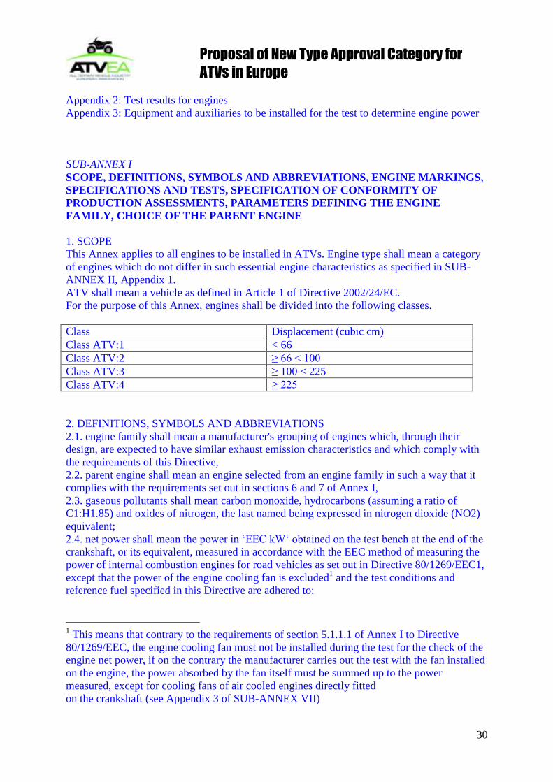
1. SCOPE
This Annex applies to all engines to be installed in ATVs. Engine type shall mean a category
of engines which do not differ in such essential engine characteristics as specified in SUB-
ANNEX II, Appendix 1.
ATV shall mean a vehicle as defined in Article 1 of Directive 2002/24/EC.
For the purpose of this Annex, engines shall be divided into the following classes.
Class Displacement (cubic cm)
Class ATV:1 < 66
Class ATV:2 ≥ 66 < 100
Class ATV:3 ≥ 100 < 225
Class ATV:4 ≥ 225
2. DEFINITIONS, SYMBOLS AND ABBREVIATIONS
2.1. engine family shall mean a manufacturer's grouping of engines which, through their
design, are expected to have similar exhaust emission characteristics and which comply with
the requirements of this Directive,
2.2. parent engine shall mean an engine selected from an engine family in such a way that it
complies with the requirements set out in sections 6 and 7 of Annex I,
2.3. gaseous pollutants shall mean carbon monoxide, hydrocarbons (assuming a ratio of
C1:H1.85) and oxides of nitrogen, the last named being expressed in nitrogen dioxide (NO2)
equivalent;
2.4. net power shall mean the power in ‗EEC kW‗ obtained on the test bench at the end of the
crankshaft, or its equivalent, measured in accordance with the EEC method of measuring the
power of internal combustion engines for road vehicles as set out in Directive 80/1269/EEC1,
except that the power of the engine cooling fan is excluded1 and the test conditions and
reference fuel specified in this Directive are adhered to;
1 This means that contrary to the requirements of section 5.1.1.1 of Annex I to Directive
80/1269/EEC, the engine cooling fan must not be installed during the test for the check of the
engine net power, if on the contrary the manufacturer carries out the test with the fan installed
on the engine, the power absorbed by the fan itself must be summed up to the power
measured, except for cooling fans of air cooled engines directly fitted
on the crankshaft (see Appendix 3 of SUB-ANNEX VII)

Proposal of New Type Approval Category for
ATVs in Europe
31
2.5. rated speed shall mean the maximum full load speed allowed by the governor as specified
by the manufacturer;
2.6. per cent load shall mean the fraction of the maximum available torque at an engine speed;
2.7. maximum torque speed shall mean the engine speed at which the maximum torque is
obtained from the engine, as specified by the manufacturer;
2.8. intermediate speed shall mean that engine speed which meets the following
requirement: for engines to be tested on cycle G1, the intermediate speed shall be 85 % of the
maximum rated speed (see section 3.5.1.2. of SUB-ANNEX IV).
2.9. adjustable parameter shall mean any physically adjustable device, system or element of
design which may affect emission or engine performance during emission testing or normal
operation;
2.10. after-treatment shall mean the passage of exhaust gases through a device or system
whose purpose is chemically or physically to alter the gases prior to release to the atmosphere;
2.11. spark ignition (SI) engine shall mean an engine which works on the spark-ignition
principle;
2.12. auxiliary emission control device shall mean any device that senses engine operation
parameters for the purpose of adjusting the operation of any part of the emission control
system;
2.13. emission control system shall mean any device, system or element of design which
controls or reduces emissions;
2.14. fuel system shall mean all components involved in the metering and mixture of the fuel;
2.16. mode length means the time between leaving the speed and/or torque of the previous
mode or the preconditioning phase and the beginning of the following mode. It includes the
time during which speed and/or torque are changed and the stabilisation at the beginning of
each mode.
2.17. Symbols and abbreviations
2.17.1. Symbols for test parameters
Symbol Unit Term
A/Fst - Stoichiometric air/fuel ratio
AP m² Cross sectional area of the isokinetic sampling probe
AT m² Cross sectional area of the exhaust pipe
Aver
m3/h
kg/h
Weighted average values for:
-volumeflow
– mass flow
C1 - Carbon 1 equivalent hydrocarbon
Cd - Discharge coefficient of the SSV
Conc ppm
Vol%
Concentration (with suffix of the component nominating)
Concc ppm
Vol%
Background corrected concentration
Concd ppm
Vol%
Concentration of the pollutant measured in the dilution air
Conce ppm Vol% Concentration of the pollutant measured in the diluted exhaust gas
d m Diameter
DF - Dilution factor
fa - Laboratory atmospheric factor

Proposal of New Type Approval Category for
ATVs in Europe
32
GAIRD kg/h Intake air mass flow rate on dry basis
GAIRW kg/h Intake air mass flow rate on wet basis
GDILW kg/h Dilution air mass flow rate on wet basis
GEDFW kg/h Equivalent diluted exhaust gas mass flow rate on wet basis
GEXHW kg/h Exhaust gas mass flow rate on wet basis
GFUEL kg/h Fuel mass flow rate
GSE kg/h Sampled exhaust mass flow rate
GT cm3/min Tracer gas flow rate
GTOTW kg/h Diluted exhaust gas mass flow rate on wet basis
Ha g/kg Absolute humidity of the intake air
Hd g/kg Absolute humidity of the dilution air
HREF g/kg Reference value of absolute humidity (10,71 g/kg)
i - Subscript denoting an individual mode (for NRSC test)
or an instantaneous value (for NRTC test)
KH - Humidity correction factor for NOx
Kp - Humidity correction factor for particulate
KV - CFV calibration function
KW,a - Dry to wet correction factor for the intake air
KW,d - Dry to wet correction factor for the dilution air
KW,e - Dry to wet correction factor for the diluted exhaust gas
KW,r - Dry to wet correction factor for the raw exhaust gas
L % Percent torque related to the maximum torque for the test speed
Md mg Particulate sample mass of the dilution air collected
MDIL kg Mass of the dilution air sample passed through the particulate sampling filters
MEDFW kg Mass of equivalent diluted exhaust gas over the cycle
MEXHW kg Total exhaust mass flow over the cycle
Mf mg Particulate sample mass collected
Mf,p mg Particulate sample mass collected on primary filter
Mf,b mg Particulate sample mass collected on back-up filter
Mgas g Total mass of gaseous pollutant over the cycle
MPT g Total mass of particulate over the cycle
MSAM kg Mass of the diluted exhaust sample passed through the particulate sampling filters
MSE kg Sampled exhaust mass over the cycle
MSEC kg Mass of secondary dilution air
MTOT kg Total mass of double diluted exhaust over the cycle
MTOTW kg Total mass of diluted exhaust gas passing the dilution tunnel over the cycle on wet basis
MTOTW,I kg Instantaneous mass of diluted exhaust gas passing the dilution tunnel on wet basis
mass g/h Subscript denoting emissions mass flow (rate)
NP - Total revolutions of PDP over the cycle
nref min-1
Reference engine speed for NRTC test
spn s-2
Derivative of the engine speed
P kW Power, brake uncorrected
p1 kPa Pressure (drop below atmospheric) depression at pump inlet of PDP

Proposal of New Type Approval Category for
ATVs in Europe
33
PA kPa Absolute pressure
Pa kPa Saturation vapour pressure of the engine intake air
(ISO 3046: psy=PSY test ambient)
PAE kW Declared total power absorbed by auxiliaries fitted for the test which are not required by
paragraph 2.4 of this Annex
PB kPa Total atmospheric pressure (ISO 3046:
Px=PX Site ambient total pressure
Py=PY Test ambient total pressure)
pd kPa Saturation vapour pressure of the dilution air
PM kW Maximum power at the test speed under test conditions (see Annex VII, Appendix 1)
Pm
kW Power measured on test bed
ps kPa Dry atmospheric pressure
q - Dilution ratio
Qs m³/s CVS volume flow rate
r
- Ratio of cross sectional areas of isokinetic probe and exhaust pipe
(r) ( Ratio of the SSV throat to inlet absolute, static pressure)
Ra % Relative humidity of the intake air
Rd % Relative humidity of the dilution air
Re - Reynolds number
Rf - FID response factor
T K Absolute temperature
t s Measuring time
Ta K Absolute temperature of the intake air
TD K Absolute dew point temperature
Tref K Reference temperature (of combustion air: 298 K)
Tsp N·m Demanded torque of the transient cycle
t10 s Time between step input and 10% of final reading
t50 s Time between step input and 50% of final reading
t90 s Time between step input and 90% of final reading
Δti s Time interval for instantaneous CFV flow
V0 m³/rev PDP volume flow rate at actual conditions
Wact kWh Actual cycle work of NRTC
WF - Weighting factor
WFE - Effective weighting factor
X0 m³/rev Calibration function of PDP volume flow rate
ΘD kg·m2 Rotational inertia of the eddy-current dynamometer
ß - Ratio of the SSV throat diameter, d, to the inlet pipe inner diameter
- Relative air/fuel ratio, actual A/F divided by stoichiometric A/F
EXH kg/m³ Density of the exhaust gas

Proposal of New Type Approval Category for
ATVs in Europe
34
2.17.2. Symbols for the chemical components
CH4 Methane
C3H8 Propane
C2H6 Ethane
CO Carbon monoxide
CO2 Carbon dioxide
DOP Di-octylphtalate
H2O Water
HC Hydrocarbons
NOx Oxides of nitrogen
NO Nitric oxide
NO2 Nitrogen dioxide
O2 Oxygen
PT Particulates
PTFE Polytetrafluoroethylene
2.17.3. Abbreviations
CFV Critical Flow Venturi
CLD Chemiluminescent detector
CI Compression Ignition
FID Flame Ionisation Detector
FS Full scale
HCLD Heated Chemiluminescent Detector
HFID Heated Flame Ionisation Detector
NDIR Non-Dispersive Infrared Analyser
NG Natural Gas
NRSC Non-Road Steady Cycle
NRTC Non-Road Transient Cycle
PDP Positive _Displacement Pump
SI Spark Ignition
SSV Sub-Sonic Venturi
3. ENGINE MARKINGS
3.2. Spark ignition engines approved in accordance with this Directive must bear:
3.2.1 the trade mark or trade name of the manufacturer of the engine;
3.3. These marks must be durable for the useful life of the engine and must be clearly legible
and indelible. If labels or plates are used, they must be attached in such a manner that in
addition the fixing is durable for the useful life of the engine, and the labels/plates cannot be
removed without destroying or defacing them.
3.4. These marks must be secured to an engine part necessary for normal engine operation and
not normally requiring replacement during engine life.

Proposal of New Type Approval Category for
ATVs in Europe
35
3.4.1. These marks must be located so as to be readily visible to the average person after the
engine has been completed with all the auxiliaries necessary for engine operation.
3.5. The coding of the engines in context with the identification numbers must be such that it
allows for the indubitable determination of the sequence of production.
3.6. Before leaving the production line the engines must bear all markings.
3.7. The exact location of the engine markings shall be declared in SUB-ANNEX VII �,
Section 1.
4. SPECIFICATIONS AND TESTS
4.2. SI engines
4.2.1. General
The components liable to affect the emission of gaseous pollutants shall be so designed,
constructed and assembled as to enable the engine, in normal use, despite the vibrations to
which it may be subjected, to comply with the provisions of this Directive.
The technical measures taken by the manufacturer must be such as to ensure that the
mentioned emissions are effectively limited, pursuant to this Directive, throughout the normal
life of the engine and under normal conditions of use in accordance with SUB-ANNEX IV,
Appendix 4.
4.2.2. Specifications concerning the emissions of pollutants.
The gaseous components emitted by the engine submitted for testing shall be measured by the
methods described in SUB-ANNEX VI (and shall include any after-treatment device).
Other systems or analysers may be accepted if they yield equivalent results to the following
reference systems:
- for gaseous emissions measured in the raw exhaust, the system shown in Figure 2 of SUB-
ANNEX VI,
- for gaseous emissions measured in the dilute exhaust of a full flow dilution system, the
system shown in Figure 3 of SUB-ANNEX VI.
4.2.2.1. The emissions of carbon monoxide, the emissions of hydrocarbons, the emissions of
oxides of nitrogen and the sum of hydrocarbons and oxides of nitrogen obtained shall not
exceed the amount shown in the table below:
Class Carbon monoxide
(CO)
(g/kWh)
Sum of hydrocarbons and
oxides of nitrogen
(g/kWh)
HC+NOx
ATV:1 610 50,0
ATV:2 610 40,0
ATV:3 610 16,1
ATV:4 610 12,1
See SUB-ANNEX IV, Appendix 4: deterioration factors included
The NOx emission for all engine classes must not exceed 10 g/kWh.
4.3. Installation on the ATV
The engine installation on the ATV shall comply with the restrictions set out in the scope of
the type-approval. Additionally the following characteristics in respect to the approval of the
engine always must be met:

Proposal of New Type Approval Category for
ATVs in Europe
36
4.3.1. intake depression shall not exceed that specified for the approved engine in SUB-
ANNEX II, Appendix 1 or 3 respectively;
4.3.2. exhaust back pressure shall not exceed that specified for the approved engine in SUB-
ANNEX II, Appendix 1 or 3 respectively.
5. SPECIFICATION OF CONFORMITY OF PRODUCTION ASSESSMENTS
5.1. With regard to the verification of the existence of satisfactory arrangements and
procedures for ensuring effective control of production conformity before granting type-
approval, the approval authority must also accept the manufacturer's registration to
harmonized standard EN 29002 (whose scope covers the engines concerned) or an equivalent
accreditation standard as satisfying the requirements. The manufacturer must provide details
of the registration and undertake to inform the approval authority of any revisions to its
validity or scope. In order to verify that the requirements of section 4.2 are continuously met,
suitable controls of the production shall be carried out.
5.2. The holder of the approval shall in particular:
5.2.1. ensure existence of procedures for the effective control of the quality of the product;
5.2.2. have access to the control equipment necessary for checking the conformity to each
approved type;
5.2.3. ensure that data of test results are recorded and that annexed documents shall remain
available for a period to be determined in accordance with the
approval authority;
5.2.4. analyse the results of each type of test, in order to verify and ensure the stability of the
engine characteristics, making allowance for variations in the industrial production process;
5.2.5. ensure that any sampling of engines or components giving evidence of nonconformity
with the type of test considered shall give rise to another sampling and another test. All the
necessary steps shall be taken to reestablish the conformity of the corresponding production.
5.3. The competent authority which has granted approval may at any time verify the
conformity control methods applicable to each production unit.
5.3.1. In every inspection, the test books and production survey record shall be presented to
the visiting inspector.
5.3.2. When the quality level appears unsatisfactory or when it seems necessary to verify the
validity of the data presented in application of section 4.2, the following procedure is adopted:
5.3.2.1. an engine is taken from the series and subjected to the test described in SUB-ANNEX
III. The emissions of the carbon monoxide, the emissions of the hydrocarbons, the emissions
of the oxides of nitrogen and the emissions of particulates obtained shall not exceed the
amounts shown in the table in section 4.2.1, subject to the requirements of section 4.2.2, or
those shown in the table in section 4.2.3 respectively;
5.3.2.2. if the engine taken from the series does not satisfy the requirements of section 5.3.2.1
the manufacturer may ask for measurements to be performed on a sample of engines of the
same specification taken from the series and including the engine originally taken. The
manufacturer shall determine the size n of the sample in agreement with the technical service.
Engines other than the engine originally taken shall be subjected to a test. The arithmetical
mean (x–) of the results obtained with the sample shall then be determined for each pollutant.
The production of the series shall then be deemed to confirm if the following condition is met:
x + k · S ≤ L 1
where:
L is the limit value laid down in section 4.2.1/4.2.3 for each pollutant considered,
k is a statistical factor depending on n and given in the following table:

Proposal of New Type Approval Category for
ATVs in Europe
37
where x is any one of the individual results obtained with the sample n.
5.3.3. The approval authority or the technical service responsible for verifying the conformity
of production shall carry out tests on engines which have been run-in partially or completely,
according to the manufacturer's specifications.
5.3.4. The normal frequency of inspections authorized by the competent authority shall be one
per year. If the requirements of section 5.3.2 are not met, the competent authority shall ensure
that all necessary steps are taken to reestablish the conformity of production as rapidly as
possible.
6. PARAMETERS DEFINING THE ENGINE FAMILY
The engine family may be defined by basic design parameters which must be common to
engines within the family. In some cases there may be
interaction of parameters. These effects must also be taken into consideration to ensure that
only engines with similar exhaust emission characteristics are included within an engine
family.
In order that engines may be considered to belong to the same engine family, the following
list of basic parameters must be common:
5.1. Combustion cycle:
− 2 cycle
− 4 cycle
6.2. Cooling medium:
- air
- water
- oil
6.3. Individual cylinder displacement, within 85% and 100% of the largest displacement
within the engine family.
6.4. Method of air aspiration
6.5. Fuel type
Not Applicable
6.6. Combustion chamber type/design
6.7. Valve and porting – configurations, size and number
6.8. Fuel system
For petrol:
- carburettor
- port fuel injection
- direct injection
6.9. Miscellaneous features
- exhaust gas recirculation
Proposal of New Type Approval Category for
ATVs in Europe
38
- water injection/emulsion
- air injection
- charge cooling system
- ignition type (compression, spark)
6.10. Exhaust after-treatment
- oxidation catalyst
- reduction catalyst
- three way catalyst
- thermal reactor
- particulate trap
7. CHOICE OF THE PARENT ENGINE
7.1. The parent engine of the family shall be selected using the primary criteria of the highest
fuel delivery per stroke at the declared maximum torque speed.
In the event that two or more engines share this primary criterion, the parent engine shall be
selected using the secondary criteria of highest fuel delivery per stroke at rated speed. Under
certain circumstances, the approval authority may conclude that the worst case emission rate
of the family can best be characterized by testing a second engine. Thus, the approval
authority may select an additional engine for test based upon features which indicate that it
may have the highest emission levels of the engines within that family.
7.2. If engines within the family incorporate other variable features which could be considered
to affect exhaust emissions, these features must also be identified and taken into account in
the selection of the parent engine.
SUB-ANNEX II
INFORMATION DOCUMENT No. ...
relating to type-approval and referring to measures against the emission of gaseous and
particulate pollutants from internal combustion engines to be installed in ATVs
Parent engine/engine type1: .......................................................................................
0 General
0.1. Make (name of undertaking): ...........................................................................
0.2. Type and commercial description of the parent- and (if applicable) of the family
engine(s)1: ...................................................................................
0.3. Manufacturer's type coding as marked on the engine(s)1:
..........................................................................................................................
0.4. Specification of machinery to be propelled by the engine2:
..........................................................................................................................
0.5. Name and address of manufacturer: ...............................................................
Name and address of manufacturer's authorized representative (if any):
..........................................................................................................................
0.6. Location, coding and method of affixing of the engine identification number:
..........................................................................................................................
0.7. Location and method of affixing of the EC approval mark:
..........................................................................................................................
0.8. Address(es) of assembly plant(s): ...................................................................
Attachments

Proposal of New Type Approval Category for
ATVs in Europe
39
1.1. Essential characteristics of the parent engine(s) (see Appendix 1)
1.2. Essential characteristics of the engine family (see Appendix 2)
1.3. Essential characteristics of engine types within the family (see Appendix 3)
2. Characteristics of engine-related parts of the ATV (if applicable)
3. Photographs of the parent engine
4. List further attachments if any
Date, file
1 Delete as appropriate.
2 As defined in SUB-ANNEX I, section 1 (e.g. ‗A‘).
Appendix 1
ESSENTIAL CHARACTERISTICS OF THE (PARENT) ENGINE1
1 DESCRIPTION OF ENGINE
1.1. Manufacturer: ..............................................................................................
1.2. Manufacturer‘s engine code: ......................................................................
1.3. Cycle: four stroke/two stroke2
1.4. Bore: .....................................................................................................mm
1.5. Stroke: ...................................................................................................mm
1.6. Number and layout of cylinders: .................................................................
1.7. Engine capacity: ................................................................................... cm3
1.8. Rated speed: ..............................................................................................
1.9. Maximum torque speed: .............................................................................
1.10. Volumetric compression ratio3: ...................................................................
1.11. Combustion system description: .................................................................
1.12. Drawing(s) of combustion chamber and piston crown: ..............................
1.13. Minimum cross sectional area of inlet and outlet ports: .............................
1.14. Cooling system
1.14.1. Liquid
1.14.1.1. Nature of liquid: ...........................................................................................
1.14.1.2. Circulating pump(s): yes/no2
1.14.1.3. Characteristics or make(s) and type(s) (if applicable): ...............................
1.14.1.4. Drive ratio(s) (if applicable): ........................................................................
1.14.2. Air
1.14.2.1. Blower: yes/no2
1.14.2.2. Characteristics or make(s) and type(s) (if applicable): ...............................
1.14.2.3. Drive ratio(s) (if applicable): ........................................................................
1.15. Temperature permitted by the manufacturer
1.15.1. Liquid cooling: maximum temperature at outlet: .......................................K
1.15.2. Air cooling: reference point: ........................................................................
Maximum temperature at reference point: ................................................K
1.15.3. Maximum charge air outlet temperature of the inlet intercooler (if applicable):
...........................................................................................K
1.15.4. Maximum exhaust temperature at the point in the exhaust pipe(s) adjacent to the outer
flange(s) of the exhaust manifold(s): ......................K
1.15.5. Lubricant temperature: minimum: ............................................................K

Proposal of New Type Approval Category for
ATVs in Europe
40
maximum: ...........................................................K 1 For the case of several parent engines to be submitted for each of them.
2 Strike out what does not apply.
3 Specify the tolerance.
1.16. Pressure charger: yes/no1
1.16.1. Make: ..........................................................................................................
1.16.2. Type: ...........................................................................................................
1.16.3. Description of the system (e.g. max charge pressure, waste-gate,
if applicable): ...............................................................................................
1.16.4. Intercooler: yes/no1
1.17. Intake system: maximum allowable intake depression at rated engine speed and at 100%
load: .............................................kPa
1.18. Exhaust system: maximum allowable exhaust backpressure at rated engine speed and at
100% load: ............................................ kPA
2. ADDITIONAL ANTI-POLLUTION DEVICES (if any, and if not covered by another
heading)
- Description and/or diagram(s): ................................................................
3. FUEL FEED
3.1. Feed pump
Pressure2 or characteristic diagram……………………...kPa
3.2. Injection system
3.2.1. Pump
3.2.1.1. Make(s): ......................................................................................................
3.2.1.2. Type(s): .......................................................................................................
3.2.1.3. Delivery: ... and ... mm3 2 per stroke or cycle at full injection at pump speed of:
...............................................................................................rpm
(rated) and ... rpm (maximum torque) respectively, or characteristic diagram.
Mention the method used: On engine/on pump bench1
3.2.1.4. Injection advance
3.2.1.4.1.Injection advance curve2: ............................................................................
3.2.1.4.2.Timing2: .......................................................................................................
3.2.2. Injection piping
3.2.2.1. Length: ..................................................................................................mm
3.2.2.2. Internal diameter: ..................................................................................mm
3.2.3. Injector(s)
3.2.3.1. Make(s):.......................................................................................................
3.2.3.2. Type(s): .......................................................................................................
3.2.3.3. Opening2 pressure or characteristic diagram: ......................................kPa
3.2.4. Governor
3.2.4.1. Make(s): ......................................................................................................
3.2.4.2. Type(s): .......................................................................................................
1 Strike out what does not apply.
2 Specify the tolerance.
3.2.4.3. Speed at which cut-off starts under full load1: ......................................rpm
3.2.4.4. Maximum no-load speed1: ....................................................................rpm
3.2.4.5. Idling speed1: ........................................................................................rpm
3.3. Cold start system
3.3.1. Make(s): ......................................................................................................
3.3.2. Type(s): .......................................................................................................

Proposal of New Type Approval Category for
ATVs in Europe
41
3.3.3. Description: .................................................................................................
4. VALVE TIMING
4.1. Maximum lift and angles of opening and closing in relation to dead centres or equivalent
data: .........................................................................
4.2. Reference and/or setting ranges2 1 Specify the tolerance.
2 Strike out what does not apply.
Appendix 2
ESSENTIAL CHARACTERISTICS OF THE ENGINE FAMILY
1. COMMON PARAMETERS1
1.1. Combustion cycle: ............................................................................................
1.2. Cooling medium: ..............................................................................................
1.3. Method of air aspiration: .................................................................................
1.4. Combustion chamber type/design: ..................................................................
1.5. Valve and porting — configuration, size and number: .....................................
1.6. Fuel system: .....................................................................................................
1.7. Engine management systems:
Proof of identity pursuant to drawing number(s):
− charge cooling system: ...............................................................................
− exhaust gas recirculation2: ..........................................................................
− water injection/emulsion2: ...........................................................................
− air injection2: ...............................................................................................
1.8. Exhaust after-treatment system2: ....................................................................
Proof of identical (or lowest for the parent engine) ratio: system capacity/fuel
delivery per stroke, pursuant to diagram number(s).
2. ENGINE FAMILY LISTING
2.1. Name of engine family: ....................................................................................
2.2. Specification of engines within this family:

Proposal of New Type Approval Category for
ATVs in Europe
42
Appendix 3
ESSENTIAL CHARACTERICTICS OF ENGINE TYPE WITHIN THE FAMILY1
1. DESCRIPTION OF ENGINE
1.1. Manufacturer: ..............................................................................................
1.2. Manufacturer‘s engine code: ......................................................................
1.3. Cycle: four stroke / two stroke2
1.4. Bore: .....................................................................................................mm
1.5. Stroke: ...................................................................................................mm
1.6. Number and layout of cylinders: .................................................................
1.7. Engine capacity: ................................................................................... cm3

Proposal of New Type Approval Category for
ATVs in Europe
43
1.8. Rated speed: ..............................................................................................
1.9. Maximum torque speed: .............................................................................
1.10. Volumetric compression ratio3: ...................................................................
1.11. Combustion system description: .................................................................
1.12. Drawing(s) of combustion chamber and piston crown: ..............................
1.13. Minimum cross sectional area of inlet and outlet ports: .............................
1.14. Cooling system
1.14.1. Liquid
1.14.1.1. Nature of liquid:
1.14.1.2. Circulating pump(s): yes/no2: ......................................................................
1.14.1.3. Characteristics or make(s) and type(s) (if applicable): ...............................
1.14.1.4. Drive ratio(s) (if applicable): ........................................................................
1.14.2. Air
1.14.2.1. Blower: yes/no2
1.14.2.2. Characteristics or make(s) and type(s) (if applicable): ...............................
1.14.2.3. Drive ratio(s) (if applicable): .......................................................................
1.15. Temperature permitted by the manufacturer
1.15.1. Liquid cooling: maximum temperature at outlet: .......................................K
1.15.2. Air cooling: reference point: ........................................................................
Maximum temperature at reference point: ................................................K
1.15.3. Maximum charge air outlet temperature of the inlet intercooler (if applicable):
...........................................................................................K
1.15.4. Maximum exhaust temperature at the point in the exhaust pipe(s) adjacent to the outer
flange(s) of the exhaust manifold(s): ......................K
1.15.5. Lubricant temperature: minimum .............................................................K
maximum ............................................................K 1 To be submitted for each engine of the family.
2 Strike out what does not apply.
3 Specify the tolerance.
1.16. Pressure charger: yes/no1
1.16.1. Make(s): ......................................................................................................
1.16.2. Type(s): .......................................................................................................
1.16.3. Description of the system (e.g. max charge pressure, waste-gate, if applicable):
...............................................................................................
1.16.4 Intercooler: yes/no1
1.17. Intake system: Maximum allowable intake depression at rated engine speed and at 100%
load load: ..............................................................kPa
1.18. Exhaust system: Maximum allowable exhaust backpressure at rated engine speed and at
100% load: ......................................................... kPA
2. ADDITIONAL ANTI-POLLUTION DEVICES (if any, and if not covered by another
heading)
− Description and/or diagram(s): ..............................................................
4. FUEL FEED FOR PETROL ENGINES
4.1. Carburettor
4.1.1. Make(s): ......................................................................................................

Proposal of New Type Approval Category for
ATVs in Europe
44
4.1.2. Type(s): .......................................................................................................
4.2. Port fuel injection: single-point or multi-point
4.2.1. Make(s): ......................................................................................................
4.2.2. Type(s): .......................................................................................................
4.3. Direct injection
4.3.1. Make(s): ......................................................................................................
4.3.2. Type(s): .......................................................................................................
4.4. Fuel flow (g/h) and air/fuel ratio at rated speed and wide open throttle
5 VALVE TIMING
5.1. Maximum lift and angles of opening and closing in relation to dead centers or equivalent
data: ....................................................................
5.2. Reference and/or setting ranges2:
5.3. Variable valve system (if applicable and where intake and/or exhaust)
5.3.1. Type: continuous or on/off2
5.3.2. Cam phase shift angle: .......................................................................
6. PORTING CONFIGURATION
6.1. Position, size, number: .................................................................................
7. IGNITION SYSTEM
7.1 Ignition coil
7.1.1: Make(s): ......................................................................................................
7.1.2. Type(s): .......................................................................................................
7.1.3. Number: ......................................................................................................
7.2. Spark plug(s)
7.2.1. Make(s): ......................................................................................................
7.2.2. Type(s): ....................................................................................................... 1 Specify the tolerance.
2 Strike out what does not apply.
7.3. Magneto
7.3.1. Make(s): ......................................................................................................
7.3.2. Type(s): ......................................................................................................
7.4. Ignition timing
7.4.1. Static advance with respect to top dead centre (crank angle degrees): ....
7.4.2. Advance curve, if applicable: ..................................................................
SUB-ANNEX IV
TEST PROCEDURE FOR SPARK IGNITION ENGINES
1. INTRODUCTION
1.1. This Annex describes the method of determining emissions of gaseous pollutants from
the engines to be tested.
1.2. The test shall be carried out with the engine mounted on a test bench and connected to a
dynamometer.
2. TEST CONDITIONS
2.1. Engine test conditions

Proposal of New Type Approval Category for
ATVs in Europe
45
The absolute temperature (Ta) of the engine air at the inlet to the engine, expressed in Kelvin,
and the dry atmospheric pressure (ps), expressed in kPa, shall be measured and the parameter
fa shall be determined according to the following provisions:
2.1.1. Test validity
For a test to be recognised as valid, the parameter fa shall be such that:
0,93 ≤ fa ≤ 1,07
2.1.2. Engines with charge air-cooling
The temperature of the cooling medium and the temperature of the charge air have to be
recorded.
2.2. Engine air inlet system
The test engine shall be equipped with an air inlet system presenting an air inlet restriction
within 10% of the upper limit specified by the manufacturer for a new air cleaner at the
engine operating conditions, as specified by the manufacturer, which result in maximum air
flow in the respective engine application.
For small spark ignition engines (<1000 cm3 displacement) a system representative of the
installed engine shall be used.
2.3. Engine exhaust system
The test engine shall be equipped with an exhaust system presenting an exhaust back pressure
within 10% of the upper limit specified by the manufacturer for the engine operating
conditions which result in the maximum declared power in the respective engine application.
For small spark ignition engines (<1000 cm3 displacement) a system representative of the
installed engine shall be used.
2.4. Cooling system
An engine cooling system with sufficient capacity to maintain the engine at normal operating
temperatures prescribed by the manufacturer shall be used. This provision shall apply to units
which have to be detached in order to measure the power, such as with a blower where the
blower (cooling) fan has to be disassembled to get access to the crankshaft.
2.5. Lubricating oil
Lubricating oil that meets the engine manufacturer's specifications for a particular engine and
intended usage shall be used. Manufacturers must use engine lubricants representative of
commercially available engine lubricants.
The specifications of the lubricating oil used for the test shall be recorded at section 1.2 of
SUB-ANNEX VII, Appendix 2 for S.I. engines and presented with the results of the test.
2.6. Adjustable carburettors
Engines with limited adjustable carburettors shall be tested at both extremes of the
adjustment.
2.7. Test fuel
The fuel shall be the reference fuel specified in SUB-ANNEX V.
The octane number and the density of the reference fuel used for test shall be recorded at
section 1.1.1 of SUB-ANNEX VII, Appendix 2 for S.I. engines.
For two-stroke engines, the fuel/oil mixture ratio must be the ratio which shall be
recommended by the manufacturer. The percentage of oil in the fuel/lubricant mixture feeding
the two-stroke engines and the resulting density of the fuel shall be recorded at section 1.1.4
of SUB-ANNEX VII, Appendix 2 for S.I. engines.

Proposal of New Type Approval Category for
ATVs in Europe
46
2.8. Determination of dynamometer settings
Emissions measurements shall be based on uncorrected brake power.
Auxiliaries necessary only for the operation of the machine and which may be mounted on the
engine shall be removed for the test. Where auxiliaries have not been removed, the power
absorbed by them shall be determined in order to calculate the dynamometer settings except
for engines where such auxiliaries form an integral part of the engine (e.g. cooling fans for air
cooled engines).
The settings of inlet restriction and exhaust pipe backpressure shall be adjusted, for engines
where it shall be possible to perform such an adjustment, to the manufacturer's upper limits, in
accordance with sections 2.2 and 2.3. The maximum torque values at the specified test speeds
shall be determined by experimentation in order to calculate the torque values for the
specified test modes. For engines which are not designed to operate over a speed range on a
full load torque curve, the maximum torque at the test speeds shall be declared by the
manufacturer. The engine setting for each test mode shall be calculated using the formula:
AEAEM PL
PPS -100
where:
S = the dynamometer setting [kW]
PM = the maximum observed or declared power at the test speed under the test conditions
(see Appendix 2 of SUB-ANNEX VII) [kW]
PAE = the declared total power absorbed by any auxiliary fitted for the test [kW] and not
required by Appendix 3 of SUB-ANNEX VII
L = the percent torque specified for the test mode.
If the ratio
03,0M
AE
P
P
the value of PAE may be verified by the technical authority granting type approval.
3. TEST RUN
3.1. Installation of the measuring equipment
The instrumentation and sampling probes shall be installed as required.
When using a full flow dilution system for exhaust gas dilution, the tailpipe shall be
connected to the system.
3.2. Starting the dilution system and engine
The dilution system and the engine shall be started and warmed up until all temperatures and
pressures have stabilised at full load and rated speed (section 3.5.2.).
3.3. Adjustment of the dilution ratio
The total dilution ratio shall not be less than four.
For CO2 or NOx concentration controlled systems, the CO2 or NOx content of the dilution air
must be measured at the beginning and at the end of each test. The pre- and post-test
background CO2 or NOx concentration measurements of the dilution air must be within 100
ppm or 5 ppm of each other, respectively.
When using a dilute exhaust gas analysis system, the relevant background concentrations shall
be determined by sampling dilution air into a sampling bag over the complete test sequence.
Continuous (non-bag) background concentration may be taken at the minimum of three
points, at the beginning, at the end, and a point near the middle of the cycle and averaged. At
the manufacturer's request background measurements may be omitted.
3.4. Checking the analysers

Proposal of New Type Approval Category for
ATVs in Europe
47
The emission analysers shall be set at zero and spanned.
3.5. Test cycle
3.5.1. Specification (c) of machinery according to section 1A(iii) of SUB-ANNEX I
The following test cycles shall be followed in dynamometer operation on the test engine
according to the given type of machinery:
cycle G1: non-handheld intermediate speed applications;
3.5.1.1. Test modes and weighting factors
Cycle G1
Mode number 1 2 3 4 5 6
Engine speed Rated speed Intermediate speed Low-idle
speed
Load % 100 75 50 25 10 0
Weighting
factor 0,09 0,2 0,29 0,3 0,07 0,05
3.5.2. Conditioning of the engine
Warming up of the engine and the system shall be at maximum speed and torque in order to
stabilise the engine parameters according to the recommendations of the manufacturer.
Note: The conditioning period should also prevent the influence of deposits from a former
test in the exhaust system. There is also a required period of stabilisation between test points
which has been included to minimise point to point influences.
3.5.3. Test sequence
Test cycles G1 shall be performed in ascending order of mode number of the cycle in
question. Each mode sampling time shall be at least 180 s. The exhaust emission
concentration values shall be measured and recorded for the last 120 s of the respective
sampling time.
For each measuring point, the mode length shall be of sufficient duration to achieve thermal
stability of the engine prior to the start of sampling.
The mode length shall be recorded and reported.
(a) For engines tested with the dynamometer speed control test configuration: During each
mode of the test cycle after the initial transition period, the specified speed shall be held to
within ± 1% of rated speed or ± 3 min-1 whichever is greater except for low idle which shall
be within the tolerances declared by the manufacturer.
The specified torque shall be held so that the average over the period during which the
measurements are being taken is within ± 2% of the maximum torque at the test speed.
(b) For engines tested with the dynamometer load control test configuration: During each
mode of the test cycle after the initial transition period, the specified speed shall be within ±
2% of rated speed or ± 3 min-1 whichever is greater, but shall in any case be held within ±
5%, except for low idle which shall be within the tolerances declared by the manufacturer.

Proposal of New Type Approval Category for
ATVs in Europe
48
During each mode of the test cycle where the prescribed torque is 50% or greater of the
maximum torque at the test speed the specified average torque over the data acquisition
period shall be held within ± 5% of the prescribed torque. During modes of the test cycle
where the prescribed torque is less than 50% of the maximum torque at the test speed the
specified average torque over the data acquisition period shall be held within ± 10% of the
prescribed torque or ± 0.5 Nm whichever is greater.
3.5.4. Analyser response
The output of the analysers shall be recorded on a strip chart recorder or measured with an
equivalent data acquisition system with the exhaust gas flowing through the analysers at least
during the last 180 s of each mode. If bag sampling is applied for the
diluted CO and CO2 measurement (see Appendix 1, section 1.4.4), a sample shall be bagged
during the last 180 s of each mode, and the bag sample analysed and recorded.
3.5.5. Engine conditions
The engine speed and load, intake air temperature and fuel flow shall be measured for each
mode once the engine has been stabilised. Any additional data required for calculation shall
be recorded (see Appendix 3, sections 1.1 and 1.2).
3.6. Rechecking the analysers
After the emission test a zero gas and the same span gas shall be used for re-checking. The
test shall be considered acceptable if the difference between the two measuring results is less
than 2%.
Appendix 1
1. MEASUREMENT AND SAMPLING PROCEDURES
Gaseous components emitted by the engine submitted for testing shall be measured by the
methods described in SUB-ANNEX VI. The methods of SUB-ANNEX VI describe the
recommended analytical systems for the gaseous emissions (section 1.1).
1.1. Dynamometer specification
An engine dynamometer with adequate characteristics to perform the test cycles described in
SUB-ANNEX IV, section 3.5.1 shall be used. The instrumentation for torque and speed
measurement shall allow the measurement of the shaft power within the given limits.
Additional calculations may be necessary.
The accuracy of the measuring equipment must be such that the maximum tolerances of the
figures given in section 1.3 are not exceeded.
1.2. Fuel flow and total diluted flow
Fuel flow meters with the accuracy defined in section 1.3 shall be used to measure the fuel
flow that will be used to calculate emissions (Appendix 3). When using a full flow dilution
system, the total flow of the dilute exhaust (GTOTW) shall be measured with a PDP or CFV –
SUB-ANNEX VI, section 1.2.1.2. The accuracy shall conform to the provisions of SUB-
ANNEX III, Appendix 2, section 2.2.
1.3. Accuracy
The calibration of all measuring instruments shall be traceable to national (international)
standards and comply with the requirements given in tables 2 and 3.
Table 2: Permissible deviations of instruments for engine related parameters

Proposal of New Type Approval Category for
ATVs in Europe
49
No. Item Permissible deviation
1 Engine speed 2% of the reading or 1% of engine's max value
whichever is larger
2 Torque 2% of the reading or 1% of engine's max value
whichever is larger
3 Fuel consumption a 2% of engine's max value
4 Air consumption a 2% of the reading or 1% of engine's max value
whichever is larger a) The calculations of the exhaust emissions as described in this Directive are, in some cases, based on
different measurement and/or calculation methods. Because of limited total tolerances for the exhaust
emission calculation, the allowable values for some items, used in the appropriate equations, must be
smaller than the allowed tolerances given in ISO 3046-3.
Table 3: Permissible deviations of instruments for other essential Parameters
No. Item Permissible deviation
1 Engine speed 2% of the reading or 1% of engine's max value
whichever is larger
2 Torque 2% of the reading or 1% of engine's max value
whichever is larger
3 Fuel consumption a 2% of engine's max value
4 Air consumption a 2% of the reading or 1% of engine's max value
whichever is larger a) The calculations of the exhaust emissions as described in this Directive are, in some cases, based on
different measurement and/or calculation methods. Because of limited total tolerances for the exhaust
emission calculation, the allowable values for some items, used in the appropriate equations, must be
smaller than the allowed tolerances given in ISO 3046-3.
1.4. Determination of the gaseous components
1.4.1. General analyser specifications
The analysers shall have a measuring range appropriate for the accuracy required for
measuring the concentrations of the exhaust gas components (section 1.4.1.1). It is
recommended that the analysers be operated such that the measured concentration falls
between 15% and 100% of full scale.
If the full scale value is 155 ppm (or ppmC) or less or if read-out systems (computers, data
loggers) that provide sufficient accuracy and resolution below 15% of full scale are used
concentrations below 15% of full scale are also acceptable. In this case, additional calibrations
are to be made to ensure the accuracy of the calibration curves - Appendix 2, section 1.5.5.2
of this Aannex.
The electromagnetic compatibility (EMC) of the equipment shall be on a level as to minimise
additional errors.
1.4.1.1. Accuracy
Proposal of New Type Approval Category for
ATVs in Europe
50
The analyser shall not deviate from the nominal calibration point by more than ± 2% of the
reading over the whole measurement range except zero, and ± 0,3% of full scale at zero. The
accuracy shall be determined according to the calibration requirements laid down in section
1.3.
1.4.1.2. Repeatability
The repeatability, shall be such that 2,5 times the standard deviation of 10 repetitive responses
to a given calibration or span gas is not greater than ± 1% of full scale concentration for each
range used above 100 ppm (or ppmC) or ± 2% of each range used below 100 ppm (or ppmC).
1.4.1.3. Noise
The analyser peak-to-peak response to zero and calibration or span gases over any 10 s period
shall not exceed 2% of full scale on all ranges used.
1.4.1.4. Zero drift
Zero response is defined as the mean response, including noise, to a zero gas during a 30-s
time interval. The drift of the zero response during a one-hour period shall be less than 2% of
full scale on the lowest range used.
1.4.1.5. Span drift
Span response is defined as the mean response, including noise, to a span gas during a 30-s
time interval. The drift of the span response during a one-hour period shall be less than 2% of
full scale on the lowest range used.
4.2. Gas drying
Exhaust gases may be measured wet or dry. Any gas-drying device, if used, must have a
minimal effect on the concentration of the measured gases. Chemical dryers are not an
acceptable method of removing water from the sample.
1.4.3. Analysers
Sections 1.4.3.1 to 1.4.3.5 describe the measurement principles to be used. A detailed
description of the measurement systems is given in SUB-ANNEX VI.
The gases to be measured shall be analysed with the following instruments. For non-linear
analysers, the use of linearising circuits is permitted.
1.4.3.1. Carbon monoxide (CO) analysis
The carbon monoxide analyser shall be of the non-dispersive infrared (NDIR) absorption
type.
1.4.3.2. Carbon dioxide (CO2) analysis
The carbon dioxide analyser shall be of the non-dispersive infrared (NDIR) absorption type.
1.4.3.3. Oxygen (O2) analysis
Oxygen analysers shall be of the paramagnetic detector (PMD), zirconium dioxide (ZRDO) or
electrochemical sensor (ECS) types.
Note: Zirconium dioxide sensors are not recommended when HC and CO concentrations are
high such as for lean burn spark ignited engines. Electrochemical sensors shall be
compensated for CO2 and NOX interference.
1.4.3.4. Hydrocarbon (HC) analysis
For direct gas sampling the hydrocarbon analyser shall be of the heated flame ionisation
detector (HFID) type with detector, valves, pipework, etc., heated so as to maintain a gas
temperature of 463 ± 10 K (190 ± 10 °C).
For diluted gas sampling the hydrocarbon analyser shall be either the heated flame ionisation
detector (HFID) type or the flame ionization detector (FID) type.
1.4.3.5. Oxides of nitrogen (NOx) analysis

Proposal of New Type Approval Category for
ATVs in Europe
51
The oxides of nitrogen analyser shall be of the chemiluminescent detector (CLD) or heated
chemiluminescent detector (HCLD) type with a NO2/NO converter, if measured on a dry
basis. If measured on a wet basis, a HCLD with converter maintained above 328 K (55 °C)
shall be used, provided the water quench check (SUB-ANNEX III, Appendix 2, section
1.9.2.2) is satisfied. For both CLD and HCLD, the sampling path shall be maintained at a wall
temperature of 328 K to 473 K (55 °C to 200 °C) up to the converter for dry measurement,
and up to the analyser for wet measurement.
1.4.4. Sampling for gaseous emissions
If the composition of the exhaust gas is influenced by any exhaust after-treatment system, the
exhaust sample shall be taken downstream of this device.
The exhaust sampling probe should be in a high pressure side of the muffler, but as far from
the exhaust port as possible. To ensure complete mixing of the engine exhaust before sample
extraction, a mixing chamber may be optionally inserted between the muffler outlet and the
sample probe. The internal volume of the mixing chamber must be not less than 10 times the
cylinder displacement of the engine under test and should be roughly equal dimensions in
height, width and depth, being similar to a cube. The mixing chamber size should be kept as
small as practicable and should be coupled as close as possible to the engine. The exhaust line
leaving the mixing chamber of muffler should extend at least 610 mm beyond the sample
probe location and be of sufficient size to minimize back pressure. The temperature of the
inner surface of the mixing chamber must be maintained above the dew point of the exhaust
gases and a minimum temperature of 338 °K (65 °C) is recommended.
All components may optionally be measured directly in the dilution tunnel, or by sampling
into a bag and subsequent measurement of the concentration in the sampling bag.
Appendix 2
1. CALIBRATION OF THE ANALYTICAL INSTRUMENTS
1.1. Introduction
Each analyser shall be calibrated as often as necessary to fulfil the accuracy requirements of
this standard. The calibration method that shall be used is described in this paragraph for the
analysers indicated in Appendix 1, section 1.4.3.
1.2. Calibration gases
The shelf life of all calibration gases must be respected. The expiry date of the calibration
gases stated by the manufacturer shall be recorded.
1.2.1. Pure gases
The required purity of the gases is defined by the contamination limits given below. The
following gases must be available for operation:
− purified nitrogen (contamination ≤ 1 ppm C, ≤ 1 ppm CO, ≤ 400 ppm CO2, ≤ 0,1 ppm NO)
− purified oxygen (purity > 99,5% vol % O2)
− hydrogen-helium mixture (40 ± 2% hydrogen, balance helium); contamination ≤ 1 ppm C, ≤
400 ppm CO2
− purified synthetic air (contamination ≤1 ppmC, ≤1 ppm CO, ≤400 ppm CO2, ≤ 0,1 ppm NO
(oxygen content between 18 and 21% vol)
1.2.2. Calibration and span gases
Mixture of gases having the following chemical compositions shall be available:
− C3H8 and purified synthetic air (see section 1.2.1.);
− CO and purified nitrogen;
− NOx and purified nitrogen (the amount of NO2 contained in this calibration gas must not
exceed 5% of the NO content);

Proposal of New Type Approval Category for
ATVs in Europe
52
− CO2 and purified nitrogen;
− CH4 and purified synthetic air;
− C2H6 and purified synthetic air.
Note: Other gas combinations are allowed provided the gases do not react with one another.
The true concentration of a calibration and span gas shall be within ± 2% of the nominal
value. All concentrations of calibration gas shall be given on a volume basis (volume percent
or volume ppm).
The gases used for calibration and span may also be obtained by means of precision blending
devices (gas dividers), diluting with purified N2 or with purified synthetic air. The accuracy
of the mixing device must be such that the concentration of the diluted calibration gases is
accurate to within ± 1,5%. This accuracy implies that primary gases used for blending must be
known to an accuracy of at least ± 1%, traceable to national or international gas standards.
The verification shall be performed at between 15 and 50% of full scale for each calibration
incorporating a blending device.
Optionally, the blending device may be checked with an instrument, which by nature is linear,
e.g. using NO gas with a CLD. The span value of the instrument shall be adjusted with the
span gas directly connected to the instrument. The blending device shall be checked at the
used settings and the nominal value shall be compared to the measured concentration of the
instrument. This difference shall in each point be within ± 0,5% of the nominal value.
1.2.3. Oxygen interference check
Oxygen interference check gases shall contain propane with 350 ppmC ± 75 ppmC
hydrocarbon. The concentration value shall be determined to calibration gas tolerances by
chromatographic analysis of total hydrocarbons plus impurities or by dynamic blending.
Nitrogen shall be the predominant diluent with the balance oxygen. Blend required for
gasoline-fuelled engine testing is as follows:
O2 interference concentration Balance
10 (9 to 11) Nitrogen
5 (4 to 6) Nitrogen
0 (0 to 1) Nitrogen
1.3. Operating procedure for analysers and sampling system
The operating procedure for analysers shall follow the start-up and operating instructions of
the instrument manufacturer. The minimum requirements given in sections 1.4 to 1.9 shall be
included. For laboratory instruments such as GC and High Performance Liquid
Chromatography (HPLC) only section 1.5.4 shall apply.
1.4 Leakage test
A system leakage test shall be performed. The probe shall be disconnected from the exhaust
system and the end plugged. The analyser pump shall be switched on. After an initial
stabilisation period all flow meters should read zero. If not, the sampling lines shall be
checked and the fault corrected.
The maximum allowable leakage rate on the vacuum side shall be 0,5% of the in-use flow rate
for the portion of the system being checked. The analyser flows and bypass flows may be
used to estimate the in-use flow rates.
Alternatively, the system may be evacuated to a pressure of at least 20 kPa vacuum (80 kPa
absolute). After an initial stabilisation period the pressure increase δp (kPa/min) in the system
shall not exceed:
δp = p / Vsyst x 0.005 x fr
Proposal of New Type Approval Category for
ATVs in Europe
53
Where:
Vsyst = system volume [l]
fr = system flow rate [l/min]
Another method is the introduction of a concentration step change at the beginning of the
sampling line by switching from zero to span gas. If after an adequate period of time the
reading shows a lower concentration compared to the introduced concentration, this points to
calibration or leakage problems.
1.5. Calibration procedure
1.5.1. Instrument assembly
The instrument assembly shall be calibrated and calibration curves checked against standard
gases. The same gas flow rates shall be used as when sampling exhaust gas.
1.5.2. Warming-up time
The warming-up time should be according to the recommendations of the manufacturer. If not
specified, a minimum of two hours is recommended for warming-up the analysers.
1.5.3. NDIR and HFID analyser
The NDIR analyser shall be tuned, as necessary, and the combustion flame of the HFID
analyser shall be optimised (section 1.9.1).
1.5.4. GC and HPCL
Both instruments shall be calibrated according to good laboratory practice and the
recommendations of the manufacturer.
1.5.5. Establishment of the calibration curves
1.5.5.1. General guidelines
(a) Each normally used operating range shall be calibrated.
(b) Using purified synthetic air (or nitrogen), the CO, CO2, NOx and HC analysers shall be
set at zero.
(c) The appropriate calibration gases shall be introduced to the analysers, the values recorded,
and the calibration curves established.
(d) For all instrument ranges except for the lowest range, the calibration curve shall be
established by at least 10 calibration points (excluding zero) equally spaced. For the lowest
range of the instrument, the calibration curve shall be established by at least 10 calibration
points (excluding zero) spaced so that half of the calibration points are placed below 15% of
the analyser's full scale and the rest are placed above 15% of full scale. For all ranges the
highest nominal concentration must be equal to or higher than 90% of full scale.
(e) The calibration curve shall be calculated by the method of least squares. A best-fit linear
or non-linear equation may be used.
(f) The calibration points must not differ from the least-squares best-fit line by more than ±
2% of reading or ± 0,3% of full scale whichever is larger.
(g) The zero setting shall be rechecked and the calibration procedure repeated, if necessary.
1.5.5.2. Alternative methods
If it can be shown that alternative technology (e.g. computer, electronically controlled range
switch, etc.) can give equivalent accuracy, then these alternatives may be used.
1.6. Verification of the calibration
Each normally used operating range shall be checked prior to each analysis in accordance
with the following procedure.

Proposal of New Type Approval Category for
ATVs in Europe
54
The calibration is checked by using a zero gas and a span gas whose nominal value is more
than 80% of full scale of the measuring range.
If, for the two points considered, the value found does not differ by more than ± 4% of full
scale from the declared reference value, the adjustment parameters may be
modified. Should this not be the case, the span gas shall be verified or a new calibration curve
shall be established in accordance with section 1.5.5.1.
1.7. Calibration of tracer gas analyser for exhaust flow measurement
The analyser for measurement of the tracer gas concentration shall be calibrated using the
standard gas.
The calibration curve shall be established by at least 10 calibration points (excluding zero)
spaced so that half of the calibration points are placed between 4% to 20% of the analyser's
full scale and the rest are in between 20% and 100% of the full scale. The calibration curve
shall be calculated by the method of least squares.
The calibration curve must not differ by more than ± 1% of the full scale from the nominal
value of each calibration point, in the range from 20% to 100% of the full scale. It also must
not differ by more than ± 2% of reading from the nominal value in the range from 4% to 20%
of the full scale. The analyser shall be set at zero and spanned prior to the test run using a zero
gas and a span gas whose nominal value is more than 80% of the analyser full scale.
1.8. Efficiency test of the NOx converter
The efficiency of the converter used for the conversion of NO2 into NO is tested as given in
sections 1.8.1 to 1.8.8 (Figure 1 of SUB-ANNEX III, Appendix 2).
1.8.1. Test set-up
Using the test set-up as shown in Figure 1 of SUB-ANNEX III and the procedure below, the
efficiency of converters can be tested by means of an ozonator.
1.8.2. Calibration
The CLD and the HCLD shall be calibrated in the most common operating range following
the manufacturer's specifications using zero and span gas (the NO content of which must
amount to about 80% of the operating range and the NO2 concentration of the gas mixture to
less than 5% of the NO concentration). The NOx analyser must be in the NO mode so that the
span gas does not pass through the converter. The indicated concentration has to be recorded.
1.8.3. Calculation
The efficiency of the NOx converter is calculated as follows:
1001(%)
dc
baEfficiency
Where:
a = NOx concentration according to section 1.8.6;
b = NOx concentration according to section 1.8.7;
c = NO concentration according to section 1.8.4;
d = NO concentration according to section 1.8.5.
1.8.4. Adding of oxygen
Via a T-fitting, oxygen or zero air is added continuously to the gas flow until the
concentration indicated is about 20% less than the indicated calibration concentration given in
section 1.8.2. (The analyser is in the NO mode.)
The indicated concentration (c) shall be recorded. The ozonator is kept deactivated throughout
the process.
1.8.5. Activation of the ozonator
Proposal of New Type Approval Category for
ATVs in Europe
55
The ozonator is now activated to generate enough ozone to bring the NO concentration down
to about 20% (minimum 10%) of the calibration concentration given in section 1.8.2. The
indicated concentration (d) shall be recorded. (The analyser is in the NO mode.)
1.8.6. NOx mode
The NO analyser is then switched to the NOx mode so that the gas mixture (consisting of NO,
NO2, 02 and N2) now passes through the converter. The indicated concentration (a) shall be
recorded. (The analyser is in the NOx mode.)
1.8.7. Deactivation of the ozonator
The ozonator is now deactivated. The mixture of gases described in section 1.8.6 passes
through the converter into the detector. The indicated concentration (b) shall be recorded.
(The analyser is in the NOx mode.)
1.8.8. NO mode
Switched to NO mode with the ozonator deactivated, the flow of oxygen or synthetic air is
also shut off. The NOx reading of the analyser shall not deviate by more than ± 5% from the
value measured according to section
1.8.2. (The analyser is in the NO mode.)
1.8.9. Test interval
The efficiency of the converter must be checked monthly.
1.8.10. Efficiency requirement
The efficiency of the converter shall not be less than 90%, but a higher efficiency of 95% is
strongly recommended.
Note: If, with the analyser in the most common range, the ozonator cannot give a reduction
from 80% to 20% according to section
1.8.5, then the highest range which will give the reduction shall be used.
1.9. Adjustment of the FID
1.9.1. Optimisation of the detector response
The HFID must be adjusted as specified by the instrument manufacturer.
A propane in air span gas should be used to optimise the response on the most common
operating range.
With the fuel and airflow rates set at the manufacturer's recommendations, a 350 ± 75 ppmC
span gas shall be introduced to the analyser. The response at a given fuel flow shall be
determined from the difference between the span gas response and the zero gas response.
The fuel flow shall be incrementally adjusted above and below the manufacturer's
specification. The span and zero response at these fuel flows shall be recorded. The difference
between the span and zero response shall be plotted and the fuel flow adjusted to the rich side
of the curve. This is the initial flow rate setting, which may need further optimisation
depending on the results of the hydrocarbon response factor and the oxygen interference
check according to sections 1.9.2 and 1.9.3.
If the oxygen interference or the hydrocarbon response factors do not meet the following
specifications, the airflow shall be incrementally adjusted above and below the manufacturer's
specifications, sections 1.9.2 and 1.9.3 should be repeated for each flow.
1.9.2. Hydrocarbon response factors
The analyser shall be calibrated using propane in air and purified synthetic air, according to
section 1.5.
Proposal of New Type Approval Category for
ATVs in Europe
56
Response factors shall be determined when introducing an analyser into service and after
major service intervals. The response factor (Rf) for a particular hydrocarbon species is the
ratio of the FID C1 reading to the gas concentration in the cylinder expressed by ppm C1.
The concentration of the test gas must be at a level to give a response of approximately 80%
of full scale. The concentration must be known to an accuracy of ± 2% in reference to a
gravimetric standard expressed in volume. In addition, the gas cylinder must be
preconditioned for 24 hours at a temperature of 298 K (25 °C) ± 5 K.
The test gases to be used and the recommended relative response factor ranges are as follows:
− methane and purified synthetic air: 1,00 ≤ Rf ≤1,15
− propylene and purified synthetic air: 0,90 ≤ Rf ≤ 1,1
− toluene and purified synthetic air: 0,90 ≤ Rf ≤ 1,10
These values are relative to the response factor (Rf) of 1,00 for propane and purified synthetic
air.
1.9.3. Oxygen interference check
The oxygen interference check shall be determined when introducing an analyser into service
and after major service intervals. A range shall be chosen where the oxygen interference
check gases will fall in the upper 50%. The test shall be conducted with the oven temperature
set as required. The oxygen interference gases are specified in section 1.2.3.
(a) The analyser shall be zeroed.
(b) The analyser shall be spanned with the 0% oxygen blend for gasoline fuelled engines.
(c) The zero response shall be rechecked. If it has changed more than 0,5% of full scale
subsections (a) and (b) of this section shall be repeated.
(d) The 5% and 10% oxygen interference check gases shall be introduced.
(e) The zero response shall be rechecked. If it has changed more than ± 1% of full scale, the
test shall be repeated.
(f) The oxygen interference (%O2) shall be calculated for each mixture in step (d) as follows:
1002
B
CBIO
D
AC ppm
Where:
A = hydrocarbon concentration (ppmC) of the span gas used in subsection (b)
B = hydrocarbon concentration (ppmC) of the oxygen interference check gases used in
subsection (d)
C = analyser response
D = percent of full scale analyser response due to A
(g) The % of oxygen interference (%O2I) shall be less than ± 3% for all required oxygen
interference check gases prior to testing.
(h) If the oxygen interference is greater than ± 3%, the air flow above and below the
manufacturer's specifications shall be incrementally adjusted, repeating section 1.9.1 for each
flow.
(i) If the oxygen interference is greater than ± 3%, after adjusting the air flow, the fuel flow
and thereafter the sample flow shall be varied, repeating section 1.9.1. for each new setting.
(j) If the oxygen interference is still greater than ± 3%, the analyser, FID fuel, or burner air
shall be repaired or replaced prior to testing. This section shall then be repeated with the
repaired or replaced equipment or gases.
1.10. Interference effects with CO, CO2, NOX and O2 analysers

Proposal of New Type Approval Category for
ATVs in Europe
57
Gases other than the one being analysed can interfere with the reading in several ways.
Positive interference occurs in NDIR and PMD instruments where the interfering gas gives
the same effect as the gas being measured, but to a lesser degree. Negative interference occurs
in NDIR instruments by the interfering gas broadening the absorption band of the measured
gas, and in CLD instruments by the interfering gas quenching the radiation. The interference
checks in sections 1.10.1 and 1.10.2 shall be performed prior to an analyser's initial use and
after major service intervals, but at least once per year.
1.10.1. CO analyser interference check
Water and CO2 can interfere with the CO analyser performance.
Therefore a CO2 span gas having a concentration of 80 to 100% of full
scale of the maximum operating range used during testing shall be bubbled through water at
room temperature and the analyser response recorded. The analyser response must not be
more than 1% of full scale for ranges equal to or above 300 ppm or more than 3 ppm for
ranges below 300 ppm.
1.10.2. NOx analyser quench checks
The two gases of concern for CLD (and HCLD) analysers are CO2 and water vapour. Quench
responses of these gases are proportional to their concentrations, and therefore require test
techniques to determine the quench at the highest expected concentrations experienced during
testing.
1.10.2.1. CO2 quench check
A C02 span gas having a concentration of 80 to 100% of full scale of the maximum operating
range shall be passed through the NDIR analyzer and the CO2 value recorded as A. It shall
then be diluted approximately 50% with NO span gas and passed through the NDIR and
(H)CLD with the CO2 and NO values recorded as B and C, respectively. The CO2 shall be
shut off and only the NO span gas is passed through the (H)CLD and the NO value recorded
as D. The quench, which shall not be greater than 3% full scale, shall be calculated as follows:
1001quenchCO% 2 xBDAD
AC
Where:
A: undiluted CO2 concentration measured with NDIR %
B: diluted CO2 concentration measured with NDIR %
C: diluted NO concentration measured with CLD ppm
D: undiluted NO concentration measured with CLD ppm
Alternative methods of diluting and quantifying CO2 and NO span gas values, such as
dynamic/mixing/blending, can be used.
1.10.2.2. Water quench check
This check applies to wet gas concentration measurements only.
Calculation of water quench must consider dilution of the NO span gas with water vapour and
scaling of water vapour concentration of the mixture to that expected during testing.
A NO span gas having a concentration of 80 to 100% of full scale to the normal operating
range shall be passed through the (H)CLD and the NO value recorded as D. The NO span gas
shall then be bubbled through water at room temperature and passed through the (H)CLD and
the NO value recorded as C. The water temperature shall be determined and recorded as F.
The mixture's saturation vapour pressure that corresponds to the bubbler water temperature
(F) shall be determined and recorded as
G. The water vapour concentration (in %) of the mixture shall be calculated as follows:

Proposal of New Type Approval Category for
ATVs in Europe
58
Bp
GH 100
and recorded as H. The expected diluted NO span gas (in water vapour) concentration shall be
calculated as follows:
1001
HDDe
and recorded as De.
The water quench shall not be greater than 3% and shall be calculated as follows:
H
H
D
CDOH
m
e
e100quench% 2
Where:
De: expected diluted NO concentration (ppm)
C: diluted NO concentration (ppm)
Hm: maximum water vapour concentration
H: actual water vapour concentration (%)
Note: It is important that the NO span gas contains minimal NO2 concentration for this check,
since absorption of NO2 in water has not been accounted for in the quench calculations.
1.10.3. O2 analyser interference
Instrument response of a PMD analyser caused by gases other than oxygen is comparatively
slight. The oxygen equivalents of the common exhaust gas constituents are shown in Table 1.
Table 1— Oxygen equivalents
Gas O2 equivalent
%
Carbon dioxide (CO2) – 0,623
Carbon monoxide (CO) – 0,354
Nitrogen oxide (NO) + 44,4
Nitrogen dioxide (NO2) + 28,7
Water (H2O) – 0,381
The observed oxygen concentration shall be corrected by the following formula if
high precision measurements are to be done:
100
..% 2 concObsOEquivalentceInterferen
1.11. Calibration intervals
The analysers shall be calibrated according to section 1.5 at least every three months or
whenever a system repair or change is made that could influence calibration.
Appendix 3
1. DATA EVALUATION AND CALCULATIONS

Proposal of New Type Approval Category for
ATVs in Europe
59
1.1. Gaseous emissions evaluation
For the evaluation of the gaseous emissions, the chart reading for a minimum of
the last 120 s of each mode shall be averaged, and the average concentrations
(conc) of HC, CO, NOx and CO2 during each mode shall be determined from the
average chart readings and the corresponding calibration data. A different type of
recording can be used if it ensures an equivalent data acquisition.
The average background concentration (concd) may be determined from the bag
readings of the dilution air or from the continuous (non-bag) background reading
and the corresponding calibration data.
1.2. Calculation of the gaseous emissions
The finally reported test results shall be derived through the following steps.
1.2.1. Dry/wet correction
The measured concentration, if not already measured on a wet basis, shall be
converted to a wet basis:
)()( dryconckwetconc w
For the raw exhaust gas:
2w22
r,wwk]dry[H%01.0,])dry[CO%]dry[CO(%005.0,1
1kk
Where is the hydrogen to carbon ratio in the fuel.
The H2 concentration in the exhaust shall be calculated:
])[%C3(][%C
])[CO%][CO(%][CO%5.0,][H
2
22
drydry
drydrydrydry
The factor kw2 shall be calculated:
)608.1,(1000
608.1,2
a
aw
H
Hk
with aH absolute humidity of the intake air as g of water per kg of dry air.
For the diluted exhaust gas:
For wet CO2 measurement:
12
1,,200
][%1 weww k
wetCOkk

Proposal of New Type Approval Category for
ATVs in Europe
60
Or, for dry CO2 measurement:
200
]dry[CO%1
)k1(kk
2
1w
2,e,ww
Where is the hydrogen to carbon ratio in the fuel.
)]/1()/11([608.1,1000
)]/1()/11([608.1,1
DFHDFH
DFHDFHk
ad
adw
Where:
dH absolute humidity of the dilution air, g of water per kg of dry air
aH absolute humidity of the intake air, g of water per kg of dry air
410ppmppm%
4.13,
2
HCCOCO concconcconcDF
For the dilution air:
1, 1 wdw kk
The factor kw1 shall be calculated from the following equations:
)]/1()/11([608.1,1000
)]/1()/11([608.1,1
DFHDFH
DFHDFHk
ad
ad
w
Where:
dH absolute humidity of the dilution air, g of water per kg of dry air
aH absolute humidity of the intake air, g of water per kg of dry air
The factor 1wk shall be calculated from the following equations:
410ppmppm%
4.13,
2
HCCOCO concconcconc
DF

Proposal of New Type Approval Category for
ATVs in Europe
61
410ppmppm%
4.13,
2
HCCOCO concconcconcDF
For the intake air (if different from the dilution air):
2, 1 waw kk
)608.1,(1000
608.1,2
a
aw
H
Hk
with Ha absolute humidity of the intake air, g of water per kg of dry air.
1.2.2. Humidity correction for NOx
As the NOx emission depends on ambient air conditions, the NOx concentration
shall be multiplied by the factor KH taking into account humidity:
233
10862.0,10030.44,6272.0, aaH HHK (for 4 stroke engines)
1HK (for 2 stroke engines) with aH absolute humidity of the intake air as g of water per kg of dry air
1.2.3. Calculation of emission mass flow rate
The emission mass flow rates Gasmass [g/h] for each mode shall be calculated as
follows.
The factor 2wk shall be calculated from the following equations:

Proposal of New Type Approval Category for
ATVs in Europe
62
(a) For the raw exhaust gas 2:
1000%
][%][%)%][(%
1
22
FUELAIRFUEL
Gasmass Gconc
wetHCwetCOCOwetCOMW
MWGas
Where:
GFUEL [kg/h] is the fuel mass flow rate;
MWGas [kg/kmole] is the molecular weight of the individual gas shown in Table 1;
Table 1 – Molecular weights Gas MWGas [kg/kmole]
NOx 46,01
CO 28,01
HC FUELHC MWMW
CO2 44,01
MWFUEL = 12,011 + α x 1,00794 + ß x 15,9994 [kg/kmole] is the fuel
molecular weight with hydrogen to carbon ratio and ß oxygen to
carbon ratio of the fuel 3;
CO2AIR is the CO2 concentration in the intake air (that is assumed
equal to 0,04% if not measured);
(b) For the diluted exhaust gas 4:
Gas mass =u x conc c x GTOTW
Where
GTOTW [kg/h] is the diluted exhaust gas mass flow rate on wet basis
that, when using a full flow dilution system, shall be determined
according to Annex III, Appendix 1, section 1.2.4;
2 In the case of NOx the concentration has to be multiplied by the humidity correction factor KH (humidity
correction factor for NOx). 3 In the ISO 8178-1 a more complete formula of the fuel molecular weight is quoted (formula 50 of
Chapter 13.5.1 (b). The formula takes into account not only the hydrogen to carbon ratio and the oxygen to
carbon ratio but also other possible fuel components such as sulphur and nitrogen. However, as the S.I. engines
of the Directive are tested with a petrol (quoted as a reference fuel in Annex V) containing usually only carbon
and hydrogen, the simplified formula is considered.
4 In the case of NOx the concentration has to be multiplied by the humidity correction factor KH (humidity
correction factor for NOx).

Proposal of New Type Approval Category for
ATVs in Europe
63
concc is the background corrected concentration:
)11( DFconcconcconc dc
with 4
10ppmppm%
4.13,
2
HCCOCO concconcconcDF
The u coefficient is shown in Table 2.
Table 2 – Values of u coefficient Gas u conc
NOx 0,001587 ppm
CO 0,000966 ppm
HC 0,000479 ppm
CO2 15,19 %
Values of the u coefficient are based upon a molecular weight of the dilute
exhaust gases equal to 29 [kg/kmole]; the value of u for HC is based upon an
average carbon to hydrogen ratio of 1:1.85.
1.2.4. Calculation of specific emissions The specific emission (g/kWh) shall be calculated for all individual components:
n
1i
i
n
1i
mass
P
Gas
gas Individuali
i
i
WF
WF
Where Pi = PM,i + PAE,i
When auxiliaries, such as cooling fan or blower, are fitted for the test, the power
absorbed shall be added to the results except for engines where such auxiliaries
are an integral part of the engine. The fan or blower power shall be determined at
the speeds used for the tests either by calculation from standard characteristics or
by practical tests (Appendix 3 of Annex VII).
The weighting factors and the number of the n modes used in the above
calculation are shown in Annex IV, section 3.5.1.1.
2. EXAMPLES
2.1. Raw exhaust gas data from a 4-stroke SI engine: not relevant
2.2. Raw exhaust gas data from a 2-stroke S.I. engine: not relevant

Proposal of New Type Approval Category for
ATVs in Europe
64
2.3. Diluted exhaust gas data from a 4-stroke S.I. engine: not relevant
Appendix 4
1. COMPLIANCE WITH EMISSION STANDARDS
1.1. The exhaust emission standards for engines in SUB-ANNEX I (4.2) apply to the
emissions of the engines for their emission durability period EDP as determined in accordance
with this Appendix.
1.2. For all engines, if, when properly tested according to the procedures in this Directive, all
test engines representing an engine family have emissions which, when adjusted by
multiplication by the deterioration factor (DF) laid down in this Appendix, are less than or
equal to each emission standard (family emission limit (FEL), where applicable) for a given
engine class, that family shall be considered to comply with the emission standards for that
engine class. If any test engine representing an engine family has emissions which, when
adjusted by multiplication by the deterioration factor laid down in this Appendix, are greater
than any single emission standard (FEL, where applicable) for a given engine class, that
family shall be considered not to comply with the emission standards for that engine class.
1.3. Small volume engine manufacturers may, optionally, take deterioration factors for
HC+NOx and CO from Tables 1 in this section, or they may calculate deterioration factors for
HC+NOx and CO according to the process described in section 1.3.1. For technologies not
covered by Tables 1 and 2 in this section, the manufacturer must use the process described in
section 1.4 in this Appendix.
Table 1: ATV HC+NOx and CO Assigned Deterioration
Factors for Small Volume Manufacturers
Engine
Class
Side Valve Engines Overhead Valve
Engines
Engines with
After treatment
HC+NOx CO HC+NOx CO DFs must be
calculated
using the
formula in para
1.3.1
ATV:1 2.1 1.1 1.5 1.1
ATV:2 2.1 1.1 1.5 1.1
ATV:3 2.1 1.1 1.5 1.1
ATV:4 1.6 1.1 1.4 1.1
1.3.1. Formula for calculating deterioration factors for engines with after treatment:
DF = [(NE * EDF) - (CC * F)]/ (NE - CC)
Where:
DF = deterioration factor
NE = new engine emission levels prior to the catalyst (g/kWh)
EDF = deterioration factor for engines without catalyst as shown in Table 1
CC = amount converted at 0 hours in g/kWh
F = 0,8 for HC and 0,0 for NOx for all classes of engines

Proposal of New Type Approval Category for
ATVs in Europe
65
F = 0,8 for CO for all classes of engines
1.4. Manufacturers shall obtain an assigned DF or calculate a DF, as appropriate, for each
regulated pollutant for all engine families.
Such DFs shall be used for type approval and production line testing.
1.4.1. For engines not using assigned DFs from Tables 1 or 2 of this section, DFs shall be
determined as follows:
1.4.1.1. On at least one test engine representing the configuration chosen to be the most likely
to exceed HC+NOx emission standards, (FELs where applicable), and constructed to be
representative of production engines, conduct (full) test procedure emission testing as
described in this Directive after the number of hours representing stabilised emissions.
1.4.1.2. If more than one engine is tested, average the results and round to the
same number of decimal places contained in the applicable standard, expressed to one
additional significant figure.
1.4.1.3. Conduct such emission testing again following ageing of the engine. The
ageing procedure should be designed to allow the manufacturer to appropriately predict the
in-use emission deterioration expected over the durability period of the engine, taking into
account the type of wear and other deterioration mechanisms expected under typical
consumer use which could affect emissions performance. If more than one engine is tested,
average the results and round to the same number of decimal places contained in the
applicable standard, expressed to one additional significant figure.
1.4.1.4. Divide the emissions at the end of the durability period (average emissions, if
applicable) for each regulated pollutant by the stabilized emissions (average emissions, if
applicable) and round to two significant
figures. The resulting number shall be the DF, unless it is less than 1,00, in which case the DF
shall be 1,0.
1.4.1.5. At the manufacturer's option additional emission test points can be scheduled between
the stabilised emission test point and the Emission Durability Period. If intermediate tests are
scheduled, the test points must be evenly spaced over the EDP (plus or minus 2 hours) and
one such
test point shall be at one-half of full EDP (plus or minus 2 hours).
For each pollutant HC+NOx and CO, a straight line must be fitted to the data points treating
the initial test as occurring at hour zero, and using the method of least-squares. The
deterioration factor is the calculated emissions at the end of the durability period divided by
the calculated emissions at zero hours.
1.4.1.6. Calculated deterioration factors may cover families in addition to the one on which
they were generated if the manufacturer submits a justification acceptable to the national type
approval authority in advance of type approval that the affected engine families can be
reasonably expected to have similar emission deterioration characteristic based on the design
and technology used.
A non-exclusive list of design and technology groupings is given below:
− conventional two-stroke engines without after treatment system,
− conventional two-stroke engines with a ceramic catalyst of the same active material and
loading, and the same number of cells per cm²,
− conventional two-stroke engines with a metallic catalyst of the same active material and
loading, same substrate and the same number of cells per cm²,

Proposal of New Type Approval Category for
ATVs in Europe
66
− two-stroke engines provided with a stratified scavenging system,
− four-stroke engines with catalyst (defined as above) with same valve technology and
identical lubrication system,
− four-stroke engines without catalyst with the same valve technology and identical
lubrication system.
2. EMISSION DURABILITY PERIODS FOR ATV ENGINES
2.1. Manufacturers shall declare the applicable EDP category for each engine family at the
time of type approval. Such category shall be the category which most closely approximates
the expected useful lives of the equipment into which the engines are expected to be installed
as determined by the engine manufacturer. Manufacturers shall retain data appropriate to
support their choice of EDP category for each engine family. Such data shall be supplied to
the approval authority upon request.
Category 1 2 3
Class ATV:1 50 125 300
Class ATV:2 125 250 500
Class ATV:3 125 250 500
Class ATV:4 250 500 1000
2.1.3. The manufacturer must satisfy the approval authority that the declared useful life is
appropriate. Data to support a manufacturer's choice of EDP category, for a given engine
family, may include but are not limited to:
− surveys of the life spans of the equipment in which the subject engines are installed,
− engineering evaluations of field aged engines to ascertain when engine performance
deteriorates to the point where usefulness and/or reliability is impacted to a degree sufficient
to necessitate overhaul or replacement,
− warranty statements and warranty periods,
− marketing materials regarding engine life,
− failure reports from engine customers, and
− engineering evaluations of the durability, in hours, of specific engine technologies, engine
materials or engine designs.
SUB-ANNEX V �
TECHNICAL CHARACTERISTICS OF REFERENCE FUEL PRESCRIBED FOR
APPROVAL TEST AND TO VERIFY CONFORMITY OF PRODUCTION
3. ATV REFERENCE FUEL FOR SI ENGINES
Note: The fuel for two-stroke engines is a blend of lubricant oil and the petrol specified
below. The fuel/oil mixture ratio must be the ratio which is recommended by the
manufacturer as specified in SUB-ANNEX IV, section 2.7.
Parameter Unit Limits (1) Test Method Publication

Proposal of New Type Approval Category for
ATVs in Europe
67
Parameter Unit Limits (1) Test Method Publication
Minimum Maximum
Research octane number, RON
Motor octane number, MON
Density at 15°C
Reid vapour pressure
Distillation
Initial boiling point
Evaporated at 100°C
Evaporated at 150°C
Final boiling point
Residue
Hydrocarbon analysis
Olefins
Aromatics
Benzene
Saturates
Carbon/hydrogen ratio
Oxidation stability (2)
Oxygen content
Existent gum
Sulphur content
Copper corrosion at 50 °C
Lead content
Phosphorus content
kg/m3
kPa
°C
% v/v
% v/v
°C
%
-
% v/v
% v/v
% v/v
% v/v
min
% m/m
mg/ml
mg/kg
g/l
g/l
95,0
85,0
748
56,0
24
49,0
81,0
190
-
-
28,0
-
-
report
480
-
-
-
-
-
-
-
-
762
60,0
-
40
57,0
87,0
215
2
10
40,0
1,0
balance
report
-
2,3
0,04
100
1
0,005
0,0013
EN 25164
EN 25163
ISO 3675
EN 12
EN-ISO 3405
EN-ISO 3405
EN-ISO 3405
EN-ISO 3405
EN-ISO 3405
ASTM D 1319
ASTM D 1319
EN 12177
ASTM D 1319
EN-ISO 7536
EN 1601
EN-ISO 6246
EN-ISO 14596
EN-ISO 2160
EN 237
ASTM D 3231
1993
1993
1995
1993
1988
1988
1988
1988
1988
-
1995
1995
1998
1995
1996
1997
1997
1998
1995
1996
1994
Note 1: The values quoted in the specification are "true values". In establishment of their limit
values the terms of ISO 4259 "Petroleum products – Determination and application of
precision data in relation to methods of test" have been applied and in fixing a minimum
value, a minimum difference of 2R above zero has been taken into account; in fixing a
maximum and minimum value, the minimum difference is 4R (R = reproducibility).
Notwithstanding this measure, which is necessary for statistical reasons, the manufacturer of
fuels should nevertheless aim at a zero value where the stipulated maximum value is 2R and
at the mean value in the case of quotations of maximum and minimum limits. Should it be
necessary to clarify the question as to whether a fuel meets the requirements of the
specifications, the terms of ISO 4259 should be applied.
Note 2: The fuel may contain oxidation inhibitors and metal deactivators normally used to
stabilise refinery gasoline streams, but detergent/dispersive additives and solvent oils must not
be added.
SUB-ANNEX VI
ANALYTICAL AND SAMPLING SYSTEM
1. GASEOUS AND PARTICULATE SAMPLING SYSTEMS

Proposal of New Type Approval Category for
ATVs in Europe
68
Figure Number Description
2 Exhaust gas analysis system for raw exhaust
3 Exhaust gas analysis system for dilute exhaust
1.1. Determination of the gaseous emissions
Section 1.1.1 and Figures 2 and 3 contain detailed descriptions of the recommended sampling
and analysing systems. Since various configurations can produce equivalent results, exact
conformance with these figures is not required. Additional components such as instruments,
valves, solenoids, pumps and switches may be used to provide additional information and
coordinate the functions of the component systems. Other components which are not needed
to maintain the accuracy on some systems, may be excluded if their exclusion is based upon
good engineering judgement.
1.1.1. Gaseous exhaust components CO, CO2, HC, NOx
An analytical system for the determination of the gaseous emissions in the raw or diluted
exhaust gas is described based on the use of:
- HFID analyser for the measurement of hydrocarbons,
- NDIR analysers for the measurement of carbon monoxide and carbon dioxide,
- HCLD or equivalent analyser for the measurement of nitrogen oxide.
For the raw exhaust gas (see Figure 2), the sample for all components may be taken with one
sampling probe or with two sampling probes located in close proximity and internally split to
the different analysers. Care must be taken that no condensation of exhaust components
(including water and sulphuric acid) occurs at any point of the analytical system.
For the diluted exhaust gas (see Figure 3), the sample for the hydrocarbons shall be taken with
another sampling probe than the sample for the other components. Care must be taken that no
condensation of exhaust components (including water and sulphuric acid) occurs at any point
of the analytical system.
Figure 2
Flow diagram of exhaust gas analysis system for CO, NOx and HC

Proposal of New Type Approval Category for
ATVs in Europe
69
zero gas
span gas
zero gas
span gas
zero gas
zero gas
V1
V1
F1 F2
F1 F2
P
P
T1
SP1
optional 2 sampling probes
T2 G1
HC
air fuel
vent
vent
vent
vent
vent
vent
vent
R3
R1 R2
FL1
T5
B
V13 V12
V11
CO
CO2
C
T3 G2
V4
V5
FL5
FL6
FL8
T4
G3
V13 V12
T5
V9
V7 V8 V10
R4
FL4
FL2
HSL1
HSL2
HSL1
SL
V3
NO
R5
zero gas
span gas
zero gas
span gas
T5
vent
O
2
FL7
V6
zero gas
span gas

Proposal of New Type Approval Category for
ATVs in Europe
70
Figure 3
Flow diagram of dilute exhaust gas analysis system for CO, CO2, NOx and HC
zero gas
span gas
zero gas
span gas
zero gas
span gas
zero gas
span gas
zero gas
V1
F1 F2
F1 F2
P
P
T1
T1
SP2
SP2
T2 G1
HC
air fuel
vent
vent
vent
vent
vent
vent
vent
R3
R1 R2
FL1
T5
B
V13 V12
V11
CO
CO2
C
T3 G2
V4
V5
FL5
FL6
FL3
T4
G3
V9
V7 V8 V10
R4
FL4
FL2
HSL1
HSL2
HSL1
SL
V3
NO
R5
V1
PSP
to PSS see figure 14
same plane
see fig. 14
BK
BKBG
DTsee fig. 13
V14
Descriptions - Figures 2 and 3
General statement:
All components in the sampling gas path must be maintained at the temperature specified for
the respective systems.
- SP1 raw exhaust gas sampling probe (Figure 2 only)
A stainless steel straight closed and multihole probe is recommended. The inside diameter
shall not be greater than the inside diameter of the sampling line. The wall thickness of the
probe shall not be greater than 1 mm. There shall be a minimum of three holes in three
different radial planes sized to sample approximately the same flow. The probe must extend
across at least 80 % of the diameter of the exhaust pipe.
- SP2 dilute exhaust gas HC sampling probe (Figure 3 only)
The probe shall:
- be defined as the first 254 mm to 762 mm of the hydrocarbon sampling line
(HSL3),
- have a 5 mm minimum inside diameter,

Proposal of New Type Approval Category for
ATVs in Europe
71
- be installed in the dilution tunnel DT (section 1.2.1.2) at a point where the
dilution air and exhaust gas are well mixed (i.e. approximately 10 tunnel
diameters downstream of the point where the exhaust enters the dilution
tunnel),
- be sufficiently distant (radially) from other probes and the tunnel wall so as to
be free from the influence of any wakes or eddies,
- be heated so as to increase the gas stream temperature to 463 K (190 °C) ± 10
K at the exit of the probe.
- SP3 dilute exhaust gas CO, CO2, NOx sampling probe (Figure 3 only)
The probe shall:
- be in the same plane as SP2,
- be sufficiently distant (radially) from other probes and the tunnel wall so as to
be free from the influence of any wakes or eddies,
- be heated and insulated over its entire length to a minimum temperature of 328
K (55 °C) to prevent water condensation.
- HSL1 heated sampling line
The sampling line provides gas sampling from a single probe to the split point(s) and
the HC analyser.
The sampling line shall:
- have a 5 mm minimum and a 13,5 mm maximum inside diameter,
- be made of stainless steel or PTFE,
- maintain a wall temperature of 463 (190 °C) ± 10 K as measured at every
separately controlled heated section, if the temperature of the exhaust gas at the
sampling probe is equal or below 463 K (190 °C),
- maintain a wall temperature greater than 453 K (180 °C) if the temperature of
the exhaust gas at the sampling probe is above 463 K (190 °C),
- maintain a gas temperature of 463 K (190 °C) ± 10 K immediately before the
heated filter (F2) and the HFID.
- HSL2 heated NOx sampling line
The sampling line shall:
- maintain a wall temperature of 328 to 473 K (55 to 200 °C) up to the converter
when using a cooling bath, and up to the analyser when a cooling bath is not
used,
- be made of stainless steel or PTFE.
Since the sampling line need only be heated to prevent condensation of water and
sulphuric acid, the samplingline temperature will depend on the sulphur content of
the fuel.
- SL sampling line for CO (CO2)

Proposal of New Type Approval Category for
ATVs in Europe
72
The line shall be made of PTFE or stainless steel. It may be heated or unheated.
- BK background bag (optional; Figure 3 only)
For the measurement of the background concentrations.
- BG sample bag (optional; Figure 3 CO and CO2 only)
For the measurement of the sample concentrations.
- F1 heated pre-filter (optional)
The temperature shall be the same as HSL1.
- F2 heated filter
The filter shall extract any solid particles from the gas sample prior to the analyser.
The temperature shall be the same as HSL1. The filter shall be changed as needed.
- P heated sampling pump
The pump shall be heated to the temperature of HSL1.
- HC
Heated flame ionization detector (HFID) for the determination of the hydrocarbons.
The temperature shall be kept at 453 to 473 K (180 to 200 °C).
- CO, CO2
NDIR analysers for the determination of carbon monoxide and carbon dioxide.
- NO2
(H)CLD analyser for the determination of the oxides of nitrogen. If a HCLD is used
it shall be kept at a temperature of 328 to 473 K (55 to 200 °C).
- C converter
A converter shall be used for the catalytic reduction of NO2 to NO prior to analysis
in the CLD or HCLD.
- B cooling bath
To cool and condense water from the exhaust sample. The bath shall be maintained
at a temperature of 273 to 277 K (0 to 4 °C) by ice or refrigeration. It is optional if
the analyser is free from water vapour interference as determined in Annex III,
Appendix 2, sections 1.9.1 and 1.9.2.
Chemical dryers are not allowed for removing water from the sample.
- T1, T2, T3 temperature sensor
To monitor the temperature of the gas stream.
- T4 temperature sensor
Temperature of the NO2-NO converter.
- T5 temperature sensor
To monitor the temperature of the cooling bath.
- G1, G2, G3 pressure gauge

Proposal of New Type Approval Category for
ATVs in Europe
73
To measure the pressure in the sampling lines.
- R1, R2 pressure regulator
To control the pressure of the air and the fuel, respectively, for the HFID.
- R3, R4, R5 pressure regulator
To control the pressure in the sampling lines and the flow to the analysers.
- FL1, FL2, FL3 flow-meter
To monitor the sample bypass flow.
- FL4 to FL7 flowmeter (optional)
To monitor the flow rate through the analysers.
- V1 to V6 selector valve
Suitable valving for selecting sample, span gas or zero gas flow to the analyser.
- V7, V8 solenoid valve
To bypass the NO2-NO converter.
- V9 needle valve
To balance the flow through the NO2-NO converter and the bypass.
- V10, V11 needle valve
To regulate the flows to the analysers.
- V12, V13 toggle valve
To drain the condensate from the bath B.
- V14 selector valve
Selecting the sample or background bag.
SUB-ANNEX VII

Proposal of New Type Approval Category for
ATVs in Europe
74

Proposal of New Type Approval Category for
ATVs in Europe
75
Appendix 2
TEST RESULTS FOR SPARK IGNITION ENGINES
1. INFORMATION CONCERNING THE CONDUCT OF THE
TEST(S) 5:
1.1. Reference fuel used for test
1.1.1. Octane number
1.1.2. State percentage of oil in mixture when lubricant and petrol are mixed
as in the case of 2-stroke engines
1.1.3. Density of petrol for 4-stroke engines and petrol/oil mixture for 2-
stroke engines
1.2. Lubricant
1.2.1. Make(s)
1.2.2. Type(s)
1.3. Engine driven equipment (if applicable)
1.3.1. Enumeration and identifying details
1.3.2. Power absorbed at indicated engine speed (as specified by the
manufacturer)
5 In case of several parent engines, to be indicated for each of them.
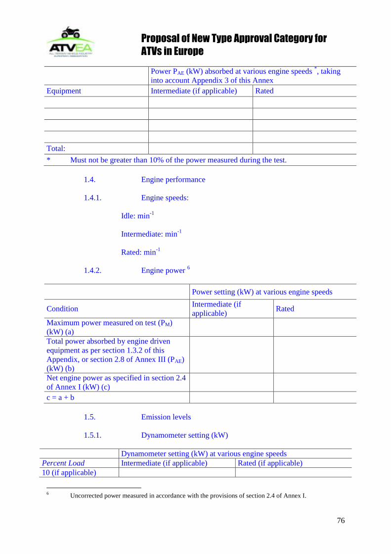
Proposal of New Type Approval Category for
ATVs in Europe
76
Power PAE (kW) absorbed at various engine speeds
*, taking
into account Appendix 3 of this Annex
Equipment Intermediate (if applicable) Rated
Total:
* Must not be greater than 10% of the power measured during the test.
1.4. Engine performance
1.4.1. Engine speeds:
Idle: min-1
Intermediate: min-1
Rated: min-1
1.4.2. Engine power 6
Power setting (kW) at various engine speeds
Condition Intermediate (if
applicable) Rated
Maximum power measured on test (PM)
(kW) (a)
Total power absorbed by engine driven
equipment as per section 1.3.2 of this
Appendix, or section 2.8 of Annex III (PAE)
(kW) (b)
Net engine power as specified in section 2.4
of Annex I (kW) (c)
c = a + b
1.5. Emission levels
1.5.1. Dynamometer setting (kW)
Dynamometer setting (kW) at various engine speeds
Percent Load Intermediate (if applicable) Rated (if applicable)
10 (if applicable)
6 Uncorrected power measured in accordance with the provisions of section 2.4 of Annex I.

Proposal of New Type Approval Category for
ATVs in Europe
77
25 (if applicable)
50
75
100
1.5.2. Emission results on the test cycle:
CO: g/kWh
HC: g/kWh
NOx: g/kWh.";
Appendix 3
EQUIPMENT AND AUXILIARIES TO BE INSTALLED FOR THE TEST TO
DETERMINE ENGINE POWER
Number Equipment and auxiliaries Fitted for emission test
1 Inlet system
Inlet manifold Yes, standard production equipment
Crankcase emission control system Yes, standard production equipment
Control devices for dual induction inlet
manifold system
Yes, standard production equipment
Air flow meter Yes, standard production equipment
Air inlet duct work Yesa)
Air filter Yesa)
Inlet silencer Yesa)
Speed-limiting device Yesa)
2 Induction-heating device of inlet manifold Yes, standard production equipment. If
possible to be set in the most favourable
condition
3 Exhaust system
Exhaust purifier Yes, standard production equipment
Exhaust manifold Yes, standard production equipment
Connecting pipes Yesb)
Silencer Yesb)
Tail pipe Yesb)
Exhaust brake Noc)
Pressure charging device Yes, standard production equipment
4 Fuel supply pump Yes, standard production equipmentd)
5 Carburation equipment
Carburettor Yes, standard production equipment
Electronic control system, air flow meter, Yes, standard production equipment
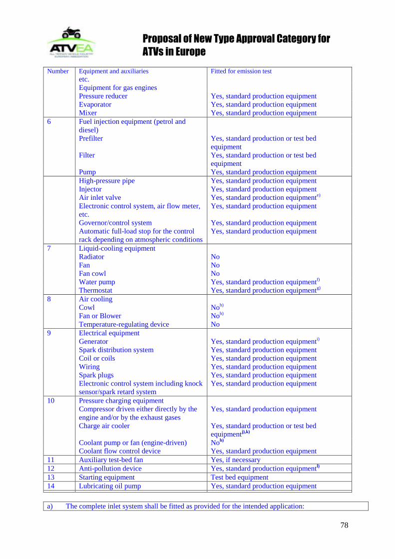
Proposal of New Type Approval Category for
ATVs in Europe
78
Number Equipment and auxiliaries Fitted for emission test
etc.
Equipment for gas engines
Pressure reducer Yes, standard production equipment
Evaporator Yes, standard production equipment
Mixer Yes, standard production equipment
6 Fuel injection equipment (petrol and
diesel)
Prefilter Yes, standard production or test bed
equipment
Filter Yes, standard production or test bed
equipment
Pump Yes, standard production equipment
High-pressure pipe Yes, standard production equipment
Injector Yes, standard production equipment
Air inlet valve Yes, standard production equipmente)
Electronic control system, air flow meter,
etc.
Yes, standard production equipment
Governor/control system Yes, standard production equipment
Automatic full-load stop for the control
rack depending on atmospheric conditions
Yes, standard production equipment
7 Liquid-cooling equipment
Radiator No
Fan No
Fan cowl No
Water pump Yes, standard production equipmentf)
Thermostat Yes, standard production equipmentg)
8 Air cooling
Cowl Noh)
Fan or Blower Noh)
Temperature-regulating device No
9 Electrical equipment
Generator Yes, standard production equipmenti)
Spark distribution system Yes, standard production equipment
Coil or coils Yes, standard production equipment
Wiring Yes, standard production equipment
Spark plugs Yes, standard production equipment
Electronic control system including knock
sensor/spark retard system
Yes, standard production equipment
10 Pressure charging equipment
Compressor driven either directly by the
engine and/or by the exhaust gases
Yes, standard production equipment
Charge air cooler Yes, standard production or test bed
equipmentj),k)
Coolant pump or fan (engine-driven) Noh)
Coolant flow control device Yes, standard production equipment
11 Auxiliary test-bed fan Yes, if necessary
12 Anti-pollution device Yes, standard production equipmentl)
13 Starting equipment Test bed equipment
14 Lubricating oil pump Yes, standard production equipment a) The complete inlet system shall be fitted as provided for the intended application:

Proposal of New Type Approval Category for
ATVs in Europe
79
where there is a risk of an appreciable effect on the engine power;
in the case of naturally aspirated spark ignition engines;
when the manufacturer requests that this should be done.
In other cases, an equivalent system may be used and a check should be made to ascertain that the intake
pressure does not differ by more than 100 Pa from the upper limit specified by the manufacturer for a clean
air filter.
b) The complete exhaust system shall be fitted as provided for the intended application:
where there is a risk of an appreciable effect on the engine power;
in the case of naturally aspirated spark ignition engines;
when the manufacturer requests that this should be done.
In other cases, an equivalent system may be installed provided the pressure measured does not differ by
more than 1000 Pa from the upper limit specified by the manufacturer.
c) If an exhaust brake is incorporated in the engine, the throttle valve shall be fixed in the fully open
position.
d) The fuel feed pressure may be adjusted, if necessary, to reproduce the pressure existing in the
particular engine application (particularly when a "fuel return" system is used).
e) The air intake valve is the control valve for the pneumatic governor of the injection pump. The
governor or the fuel injection equipment may contain other devices which may affect the amount of injected
fuel.
f) The cooling-liquid circulation shall be operated by the engine water pump only. Cooling of the
liquid may be produced by an external circuit, such that the pressure loss of this circuit and the
pressure at the pump inlet remain substantially the same as those of the engine cooling system.
g) The thermostat may be fixed in the fully open position.
h) When the cooling fan or blower is fitted for the test, the power absorbed shall be added to the
results, except for cooling fans of air cooled engines directly fitted on the crankshaft. The fan or blower
power shall be determined at the speeds used for the test either by calculation from standard characteristics
or by practical tests.
i) Minimum power of the generator: the electrical power of the generator shall be limited to that
necessary for operation of accessories which are indispensable for engine operation. If the connection of a
battery is necessary, a fully charged battery in good condition shall be used.
j) Charge air-cooled engines shall be tested with charge air cooling, whether liquid- or air-cooled, but
if the manufacturer prefers, a test bench system may replace the air cooler. In either case, the measurement
of power at each speed shall be made with the maximum pressure drop and the minimum temperature drop
of the engine air across the charge air cooler on the test bench system as specified by the manufacturer.
k) These may include, for example, exhaust-gas recirculation (EGR)-system, catalytic converter,
thermal reactor, secondary air-supply system and fuel evaporation protecting system.
l) The power for electrical or other starting systems shall be provided from the test bed.

Proposal of New Type Approval Category for
ATVs in Europe
80
3.3 Sound Testing
DIRECTIVE 97/24/EC OF THE EUROPEAN PARLIAMENT AND OF THE COUNCIL on
certain components and characteristics of two or three-wheel motor vehicles as last amended
by Directive 2006/27/EC
CHAPTER 9 PERMISSIBLE SOUND LEVEL AND EXHAUST SYSTEM OF TWO OR
THREE-WHEEL MOTOR VEHICLES
LIST OF ANNEXES
ANNEX I Sound level limits in dB(A) and dates of entry into force for component type-
approval regarding the permissible sound level of a type of two or three-wheel motor vehicle
ANNEX II Requirements for two-wheel mopeds
1. Definitions
2. Component type-approval in respect of the sound level and original exhaust system, as a
separate technical unit, of a type of two-wheel moped
3. Component type-approval of a non-original exhaust system or components thereof, as
separate technical units, for a type of two-wheel moped
Appendix 1A Information document in respect of the permissible sound level and original
exhaust system of a type of two-wheel moped
Appendix 1B Component type-approval certificate in respect of the permissible sound level
and original exhaust system(s) of a type of two-wheel moped
Appendix 2A Information document in respect of a non-original exhaust system or
component(s) thereof, as separate technical unit(s), for a type of two-wheel moped
Appendix 2B Component type-approval certificate in respect of a non-original exhaust system
for a type of two-wheel moped
ANNEX III Requirements for motorcycles
1. Definitions
2. Component type-approval in respect of the sound level and original exhaust system, as a
separate technical unit, of a type of motorcycle

Proposal of New Type Approval Category for
ATVs in Europe
81
3. Component type-approval of a non-original exhaust system or components thereof, as
separate technical units, for a type of motorcycle
Appendix 1A Information document in respect of the permissible sound level and original
exhaust system of a type of motorcycle
Appendix 1B Component type-approval certificate in respect of the permissible sound level
and original exhaust system(s) of a type of motorcycle
Appendix 2A Information document in respect of a non-original exhaust system or
component(s) thereof, as separate technical unit(s), for a type of motorcycle
Appendix 2B Component type-approval certificate in respect of a non-original exhaust system
for a type of motorcycle
ANNEX IV Requirements for three-wheel mopeds and tricycles
1. Definitions
2. Component type-approval in respect of the sound level and original exhaust system, as a
separate technical unit, of a type of three-wheel moped or tricycle
3. Component type-approval of a non-original exhaust system or components thereof, as
separate technical units, for a type of three-wheel moped or tricycle
Appendix 1A Information document in respect of the permissible sound level and original
exhaust system of a type of three-wheel moped or tricycle
Appendix 1B Component type-approval certificate in respect of the permissible sound level
and original exhaust system(s) of a type of three-wheel moped or tricycle
Appendix 2A Information document in respect of a non-original exhaust system or
component(s) thereof, as separate technical unit(s), for a type of three-wheel moped or
tricycle
Appendix 2B Component type-approval certificate for a non-original exhaust system for a
type of three-wheel moped or tricycle
ANNEX V Production conformity requirements
ANNEX VI Marking requirements
ANNEX VII Test track specifications
ANNEX VIII

Proposal of New Type Approval Category for
ATVs in Europe
82
The sound level of the ATV as defined in article 1 of Directive 2002/24/EC, when
measured under the conditions set out in this Annex, may not exceed the following
levels:
80 dB(A)
I.2. Measuring instruments
The noise emitted by the ATV shall be measured by means of a sound-level meter of
the type described in Publication 179, 1st Edition (1965) of the International
Electrotechnical Commission.
I.3. Conditions of measurement
Measurements shall be made on the unladen ATV in a sufficiently silent and open area
(ambient noise and wind noise at least 10 dB(A) below the noise being measured).
This area may take the form, for instance, of an open space of 50 meter radius having
a central part of at least 20 meters radius which is practically level ; it may be surfaced
with concrete, asphalt, or similar material and may not be covered with powdery snow,
tall grass, loose soil or ashes.
The surface of the test track shall be such as not to cause excessive tyre noise. This
condition applies only to measurement of the noise made by the ATV in motion.
Measurement shall be carried out in fine weather with little wind. No person other
than the observer taking the readings from the apparatus may remain near the ATV or
the microphone, as the presence of spectators near either the ATV or the microphone
may considerably affect the readings from the apparatus. Marked fluctuations of the
pointer which appear to be unrelated to the characteristics of the general sound level
shall be ignored in taking readings.
I.4. Method of measurement
I.4.1. Measurement of noise of the ATV in motion (for type-approval).
At least two measurements shall be made on each side of the ATV. Preliminary
measurements may be made for adjustment purposes but shall be disregarded.
The microphone shall be situated 1.2 meters above ground level at a distance of 7.50
meters from the path of the ATV‘s centre line, CC, measured along the perpendicular
PP' to that line (figure 1).
Two lines AA' and BB', parallel to line PP' and situated respectively 10 meters forward
and 10 meters rearward of the line, shall be marked out on the test track. The ATV shall
approach line AA' at a steady speed, as specified below. The throttle shall then be kept

Proposal of New Type Approval Category for
ATVs in Europe
83
in such position that the speed remains constant until the rear of the ATV 7 crosses line
BB‘; the throttle shall then be closed again as rapidly as possible.
The maximum sound level recorded shall constitute the result of the measurement.
I.4.1.1. The test speed shall be 35 km/h.
I.4.1.2. Interpretation of results
I.4.1.2.1. To take account of inaccuracies in the measuring instruments, the result
obtained from each measurement shall be determined by deducting 1 dB (A) from the
meter reading.
I.4.1.2.2. Measurements shall be considered valid if the difference between two
consecutive measurements on the same side of the ATV does not exceed 2 dB(A).
I.4.1.2.3. The highest sound level measured shall constitute the test result. Should that
result exceed by 1 dB(A) the maximum permissible sound level, two further
measurements shall be made. Three of the four measurements thus obtained must fall
within the prescribed limits.
I.4.2. Measurement of noise of stationary ATV (not required for type-approval, but
must be recorded).
I.4.2.1. Position of sound-level meter
Measurements shall be made at point X (shown in figure 2) at a distance of 7 meters
from the nearest surface of the ATV.
The microphone shall be situated 1.2 meters above ground level.
I.4.2.2. Number of measurements
At least two measurements shall be made.
I.4.2.3. ATV test conditions
The engine of an ATV without a speed governor shall be run at three-quarters of the
rpm speed at which, according to the ATV manufacturer, it develops its maximum
power. The rpm speed of the engine shall be measured by means of an independent
instrument, e.g. a roller bed and a tachometer. If the engine is fitted with a governor
7 If the ATV includes a trailer, this shall not be taken into account in determining
when line BB' is crossed.

Proposal of New Type Approval Category for
ATVs in Europe
84
preventing the engine from exceeding the speed at which it develops its maximum
power, it shall be run at the maximum speed permitted by the governor.
Before taking any measurements, the engine shall be brought to its normal running
temperature.
I.4.2.4. Interpretation of results
All sound-level readings recorded shall be given in the report.
The method used to calculate the engine power shall also be shown where possible.
The state of loading of the ATV must also be given.
The measurements shall be considered valid if the difference between two consecutive
measurements on the same side of the ATV does not exceed 2 dB(A).
The maximum figure recorded shall constitute the result of the measurement.
II. EXHAUST SYSTEM (SILENCER)
II.1. If the ATV is fitted with a device designed to reduce the exhaust noise (silencer),
the requirements of this Item II shall apply. If the inlet of the engine is fitted with an
air filter which is necessary in order to ensure compliance with the permissible sound
level, the filter shall be considered to be part of the silencer, and the requirements of
this Item II shall also apply to that filter.
The exhaust tailpipe must be positioned in such a way that the exhaust gases are not
directed towards the operator.
II.2. A drawing of the exhaust system must be annexed to the ATV type-approval
certificate
II.3. The silencer must be marked with a reference to its make and type which is
clearly legible and indelible.
II.4. The use of fibrous absorbent material is permitted in the construction of silencers
only if the following conditions are fulfilled:
II.4.1. The fibrous absorbent material may not be placed in those parts of the silencer
through which gases pass;
II.4.2. Suitable devices must ensure that the fibrous absorbent material is kept in place
for the whole time that the silencer is being used;
II.4.3. The fibrous absorbent material must be resistant to a temperature at least 20 %
higher than the operating temperature (degrees C°) which may occur in the region of
the silencer where those fibrous absorbent materials are situated.

Proposal of New Type Approval Category for
ATVs in Europe
85
3.4 Brakes
Council Directive 93/14/EEC (as last amended by Directive 2006/27/EC)
on the braking of two or three-wheel motor vehicles
ANNEX
1. DEFINITIONS
2. CONSTRUCTION AND FITTING REQUIREMENTS
2.1. General
2.1.1. Braking device
2.1.1.1. The braking device must be so designed, constructed and fitted as to enable the
vehicle in normal use to comply with the provisions of this Directive, despite the vibration to
which it may be subjected.
2.1.1.2. In particular, the braking device shall be so designed, constructed and fitted as to be
able to resist the corroding and ageing phenomena to which it is exposed.
2.1.2. Functions of the braking device
The braking device defined in 1.2 must fulfil the following conditions:
2.1.2.1. Service braking
The service braking must make it possible to control the movement of the vehicle and to halt
it safely, speedily and effectively, whatever its speed and load, on any up or down gradient. It
must be possible to graduate this braking action. The driver must be able to achieve this
braking action from his driving seat without removing his hands from the steering control.
2.1.2.2. Secondary (emergency) braking (where applicable)
The secondary (emergency) braking must make it possible to halt the vehicle within a
reasonable distance in the event of failure of the service braking. It must be possible to
graduate this braking action. The driver must be able to obtain this braking action from his
driving seat while keeping at least one hand on the steering control. For the purposes of these
provisions it is assumed that not more than one failure of the service braking can occur at one
time.
2.1.2.3. Parking brake (if fitted)

Proposal of New Type Approval Category for
ATVs in Europe
86
The parking brake must make it possible to halt the vehicle stationary on up or down gradient
even in the absence of the driver, the working parts being then held in the locked position by a
purely mechanical device. The driver must be able to achieve this braking action from his
driving seat.
2.2. Characteristics of braking devices
2.2.1. Every two-wheel moped or two-wheel motorcycle shall be equipped with two service
braking devices, with independent controls and transmissions, one acting at least on the front
wheel and the other at least on the rear wheel.
2.2.1.1. The two service braking devices may have a common braking so long as a failure in
one braking device does not affect the performance of the other. Certain parts, such as the
brake itself, the brake cylinders and their pistons (except the seals), the push rods and the cam
assemblies of the brakes, shall not be regarded as liable to breakage if they are amply
dimensioned, are readily accessible for maintenance and exhibit sufficient safety features.
2.2.1.2. A parking braking device is not compulsory.
2.2.2. Every motorcycle with sidecar shall be equipped with the braking devices which would
be required if it had no sidecar; if these devices enable the required performance to be
achieved in tests of the vehicle with sidecar, a brake on the sidecar wheel shall not be
required; a parking braking device is not compulsory.
2.2.3. Every three-wheel moped must be equipped with:
2.2.3.1. either two independent service braking devices which together actuate the brakes on
all of the wheels; or
2.2.3.2. a service braking device which operates on all the wheels, and a secondary
(emergency) braking device which may be the parking brake.
2.2.3.3. In addition, every three-wheel moped must be equipped with a parking braking device
acting on the wheel or wheels of at least one axle. The parking braking device, which may be
one of the two devices specified in 2.2.3.1, must be independent of the device acting on the
other axle or axles.
2.2.4. Every tricycle must be equipped with:
2.2.4.1. a foot-controlled serviced braking device which operates on all wheels, and a
secondary (emergency) braking device which may be the parking brake; and
2.2.4.2. a parking braking device acting on the wheels of at least one axle. The control of the
parking device must be independent of the control of the service braking device.
2.2.4.3. Every ATV must be equipped with:

Proposal of New Type Approval Category for
ATVs in Europe
87
2.2.4.3.1. Either a foot-controlled service braking device which operates on all wheels, and a
secondary (emergency) braking device which may be the parking brake
or a hand operated service braking device which operates on all wheels and a secondary
(emergency) braking device which may be the parking brake,
or two separate service brake devices controlled by either hand or foot each of which operates
on all wheels on one axle such that all wheels on both axles provide braking force and a
secondary (emergency) braking device which may be the parking brake; and
2.2.4.3.2. a parking braking device acting on the wheels of at least one axle. The control of the
parking device must be independent of the control of the service braking device.
2.2.5. The braking devices must act on brake surfacespermanently connected to the wheels
either rigidly or through components unlikely to fail.
2.2.6. The component parts of all braking devices, where attached to the vehicle, must be so
secured that the braking devices do not fail in their function under normal operating
conditions.
2.2.7. The braking devices shall operate freely when correctly lubricated and adjusted.
2.2.7.1. Wear of the brakes must be capable of being easily taken up by means of either
manual or automatic adjustment. The brakes shall be capable of being adjusted to an efficient
operating position until the brake linings have worn to the point of requiring replacement.
2.2.7.2. The control and the components of the transmission and of the brakes must possess a
reserve of travel such that when the brakes become heated and the brake linings have reached
maximum permitted degree of wear, effective braking is ensured without immediate
adjustment being necessary.
2.2.7.3. When correctly adjusted the components of the braking device must not, when
operated, contact anything other than the intended parts.
2.2.8. In braking devices where the transmission is hydraulic, the receptables containing the
reserve fluid must be so designed and constructed that the level of the reserve fluid can be
easily checked.
This provision does not apply to mopeds with a maximum speed of 25 km/h or lower.

Proposal of New Type Approval Category for
ATVs in Europe
88
3.5 Passenger Handholds
COUNCIL DIRECTIVE 93/32/EEC on passenger hand-holds on two and three-wheel motor
vehicles as last amended by Directive 1999/24/EC.
Article 1
This Directive and its Annex apply to passenger hand-holds of all types of two-wheel vehicles
and ATVs as defined in Article 1 of Council Directive 92/61/EEC.
Article 2
The procedure for the granting of component type-approval in respect of passenger hand-
holds on a type of two-wheel motor vehicle or ATV and the conditions governing the free
movement of said vehicles shall be as laid down in Chapters II and III of Directive
92/61/EEC.
Appendix 1 Information document in respect of passenger hand-holds on a type of two-wheel
motor vehicle or ATV
(to be attached to the application for component type-approval if this is submitted separately
from the application for vehicle type-approval)
Order No (assigned by the applicant): .
The application for component type-approval in respect of passenger hand-holds on a two-
wheel motor vehicle or ATV must contain the information set out under the following points
in Annex II to Council Directive 92/61/EEC:
- Part A, sections:
- 0.1
- 0.2
- 0.4 to 0.6;
- Part B, sections:
- 1.5 to 1.5.2.

Proposal of New Type Approval Category for
ATVs in Europe
89
Appendix 2 Name of administration
Component type-approval certificate in respect of restraint devices for passengers on a type of
two-wheel motor vehicle or ATV
MODEL
Report No . by technical service . date .
Component type-approval No: . Extension No: .
1. Trade mark or name of vehicle: .
2. Type of vehicle: .
3. Manufacturer's name and address: .
.
4. Name and address of manufacturer's representative (if any):.
.
5. Date vehicle submitted for test: .
6. Component type-approval granted/refused (1):
7. Place: .
8. Date: .
9. Signature: .
(1) Delete as appropriate.

Proposal of New Type Approval Category for
ATVs in Europe
90
3.6 Foot-Wells
Article 1
1. This Directive and its Annex apply to the footrests of all unbodied quadricycles, as defined
within category L8e in Directive 2002/24/EC, which are intended for passenger carriage.
This Directive does not apply to the following vehicles:
(a) mopeds;
(b) motorcycles;
(c) motor tricycles; or
(d) quadricycles of category L6e and L7e.
ANNEX
1. GENERAL REQUIREMENTS
Where provision is made for carriage of a passenger, the vehicle (unbodied quadricycle) must
be fitted with a footrest on each side of the vehicle. That footrest must take the form of a
footpeg or floorboard.
1.1 Passenger Footrests
The passenger footrests must be positioned in such a way that they may easily be used
by the passenger. These footrests must be symmetrical to the median longitudinal
plane of the vehicle.
1.2 Passenger Footrest Location
The passenger footrest must be located in such a position that provides a minimum of
205 mm [8 inches] of distance between the operator footrests and the passenger
footrests. This distance must be measured horizontally and parallel to the longitudinal
plane of the vehicle. The measured distance shall be between the center point of the
operator footrest (P1) and passenger footrest (P2) on one side of the vehicle as shown
in Figure 1.
The passenger footrests in their entireties must be within the area defined by the
wheels or fenders when viewed from above.
1.3 Passenger Footrest Load Test

Proposal of New Type Approval Category for
ATVs in Europe
91
Each passenger footrest must be designed in such a way that they withstand, without
breakage or permanent deformation, a vertical load of 2 000 N [450 lbf] applied
statically to the centre of the footrest (P2) at a maximum pressure of 2 MPa [290
lbf/in^2].
1.4 Passenger Footrest Probe Test
1.4.1 Compliance shall be determined by introduction of a probe, whose end is a rigid flat
plane surface 75 mm (3 inch) in diameter, in the prescribed directions to the zones as
described in 1.4.2 and 1.4.3 and as shown in Figures 1 and 2.
1.4.2 The probe shall be introduced end-first in a vertical and downward direction to the
zone described in 1.4.4 and shown by the shaded portion of Figure 1. The end of the
probe in its entirety shall remain within the limits of the zone. It shall not penetrate the
zone sufficiently to touch the ground when applied with a force 445 N [100 lbf].
1.4.3 The probe shall be introduced end first in a horizontal and rearward direction to the
zone described in 1.4.5 and shown by the shaded portion of Figure 2. The end of the
probe in its entirety shall remain within the limits of the zone. It shall not penetrate the
zone sufficiently to touch the rear tire when applied with a force of 90 N [20 lbf].
1.4.4 The zone shown in Figure 1 is defined as bounded by:
(1) The vertical projection of the rear edge of the footrest.
(2) The vertical plane (line AA), parallel to the vehicle longitudinal plane of
symmetry, that passes through the inside edge of the footrest.
(3) The vertical projection of the intersection of a horizontal plane passing through
the top surface of the footrest, and the rear fender or other structure.
(4) The vertical plane passing through point D and tangent to the outer front
surface of the rear tire.
(a) For footpegs, Point D is defined as the intersection of the lateral
projection of the rearmost point of the footpeg and the longitudinal
projection of the outermost point of the footpeg.
(b) For footboards, Point D is defined as the intersection of two lines. The
first is a line perpendicular to the vehicle longitudinal plane of
symmetry and one-third of the distance from the front edge of the rear
tire to the rear edge of the front tire. The second is a line parallel to the
vehicle longitudinal plane of symmetry and one-half the distance
between the inside edge of the footboard and the outside surface of the
rear tire.
1.4.5 The zone shown in Figure 2 is defined as bounded by:
(1) The horizontal plane passing through the lowest surface of the footrest on
which the passengers foot (boot) rests (plane G).
(2) The vertical plane (line AA), parallel to the vehicle longitudinal plane of
symmetry, that passes through the inside edge of the footrest.
(3) The horizontal plane 100 mm [4 inches] above plane G.

Proposal of New Type Approval Category for
ATVs in Europe
92
(4) The vertical plane (line BB) parallel to the vehicle longitudinal plane of
symmetry and 50 mm [2 inches] inboard of the outer surface of the rear tire.
Figure 1
Passenger footrest – top view

Proposal of New Type Approval Category for
ATVs in Europe
93
Figure 2
Passenger footrest – front view

Proposal of New Type Approval Category for
ATVs in Europe
94
3.7 Lighting
COUNCIL DIRECTIVE 93/92/EEC as last amended by Directive 2000/73/EC on the
installation of lighting and light-signalling devices on two- or three-wheel motor vehicles
ANNEX III
REQUIREMENTS CONCERNING THREE-WHEEL MOPEDS AND LIGHT
QUADRICYCLES
(Insert following new paragraph 5a between paragraph 5 and 6)
5a. The lighting devices referred to in sections 1.1, 1.2, 1.4 and 1.6 and complying with the
requirements of following US-SAE(Society of Automotive Engineers ) technical standards,
shall also be permitted on ATVs (category L8e).
- SAE J1623 [February 1994] for All-Terrain Vehicle Headlamps
- SAE J278 [March 2006] for Snowmobile Stop Lamp, and/or, SAE J586 March 2000 for
Stop Lamps for Use on Motor Vehicles Less Than 2032 mm in Overall Width
- SAE J585 [March 2000] for Tail Lamps (Rear Position Lamps) for Use on Motor
Vehicles Less Than 2032 mm in Overall Width
Note: Latest version of the SAE standards shall be used.
ANNEX VI
REQUIREMENTS CONCERNING TRICYCLES
(Insert following new paragraph 5a between paragraph 5 and 6)
5a. The lighting devices referred to in sections 1.1, 1.2, 1.4 and 1.6 and complying with the
requirements of following US-SAE(Society of Automotive Engineers ) technical standards,
shall also be permitted on ATVs (category L9e).
- SAE J1623 [February 1994] for All-Terrain Vehicle Headlamps
- SAE J278 [March 2006] for Snowmobile Stop Lamp, and/or, SAE J586 March 2000 for
Stop Lamps for Use on Motor Vehicles Less Than 2032 mm in Overall Width
- SAE J585 [March 2000] for Tail Lamps (Rear Position Lamps) for Use on Motor
Vehicles Less Than 2032 mm in Overall Width
Note: Latest version of the SAE standards shall be used.

Proposal of New Type Approval Category for
ATVs in Europe
95
3.8 Speed Plate
COUNCIL DIRECTIVE 93/94/EEC as last amended by Directive 1999/26/EC relating to the
space for mounting the rear registration plate of two or three-wheel vehicles and to the space
for mounting the in-use speed limit plate of ATVs.
Article 1
This Directive and its Annex apply to the space for mounting the rear registration plate of all
types of vehicle as defined in Article 1 of Directive 92/61/EEC. It also applies to the space for
mounting the in-use speed limit plate for ATVs.
Article 2
The procedure for the granting of component type-approval in respect of the space for
mounting the rear registration plate of two or three-wheel motor vehicle and of the space for
mounting an in-use speed limit plate of ATVs and the conditions governing the free
movement of such vehicles shall be as laid down in Chapters II and III of Directive
92/61/EEC.
ANNEX
1. DIMENSIONS
The dimensions of the space for mounting the rear registration plate of two or three-wheel
motor vehicles(1) are as follows:
1.1. Mopeds, and light quadricycles without a body and light ATVs
1.1.1. Width: 100 mm;
1.1.2. Height: 175 mm;
or
1.1.3. Width: 145 mm;
1.1.4. Height: 125 mm.
1.2. Motorcycles, tricycles up to a maximum power of 15 kW, and quadricycles other than
light quadricycles, without a body and ATVs other than light ATVs:
1.2.1. Width: 280 mm;

Proposal of New Type Approval Category for
ATVs in Europe
96
1.2.2. Height: 210 mm.
1.3. Tricycles with a maximum power exceeding 15 kW, light quadricycles fitted with a body
and quadricycles other than light quadricycles fitted with a body:
1.3.1. The provisions for passenger cars as set out in Directive 70/222/EEC shall apply.
1.4. Dimensions of the space for the in-use speed limit plate of ATVs
1.4.1. Diameter: 150 mm
2. GENERAL LOCATION
2.1. The mounting for the rear registration plate of a motorcycle, motorcycle combination or
tricycle and the mounting for the in-use speed limit plate of an ATV must be located at the
rear of the vehicle in such a manner that:
2.1.1. the plate can be positioned within the longitudinal planes passing through the outer
extremities of the vehicle.
3. INCLINATION
3.1. The rear registration plate and the in-use speed plate:
3.1.1. must be at right angles to the median longitudinal plane of the vehicle;
3.1.2. may be inclined from the vertical by not more 30°, with the vehicle unladen, when
the backing plate for the registration number and/or in-use speed limit plate faces upwards;
3.1.3. may be inclined by not more than 15° from the vertical, with the vehicle unladen,
when the backing plate for the registration number and/or in-use speed limit plate faces
downwards;
4. MAXIMUM HEIGHT
4.1. No point on the space for mounting the registration plate and/or in-use speed limit plate
may be more than 1,5 m above the ground when the vehicle is unladen.
5. MINIMUM HEIGHT
5.1. No point on the space for mounting the registration plate and/or in-use speed limit plate
shall be less than 0,20 m above the ground, or less than the radius of the wheel above the
ground if that is less than 0,20 m, when the vehicle is unladen.
6. GEOMETRIC VISIBILITY
6.1. The space for mounting the plate and/or in-use speed limit plate must be visible within a
space bordered by two dihedrals: one with a horizontal edge defined by two planes passing
Proposal of New Type Approval Category for
ATVs in Europe
97
through the upper and lower horizontal edges of the space for mounting the plate, the angles
of which in relation to the horizontal are shown in Figure 1; the other with a perceptibly
vertical edge defined by two planes passing through each side of the plate, the angles of which
in relation to the median longitudinal plane of the vehicle are shown in Figure 2.
Appendix 1 Information document in respect of the space for mounting the rear registration
plate of a type of two or three-wheel motor vehicle and of the space for mounting the in-use
speed limit plate of ATVs
(to be attached to the application for component type-approval where this is submitted
separately from the application for vehicle type-approval
Order No (assigned by the applicant): .
The application for component type-approval in respect of the space for mounting the rear
registration plate of a type of two or three-wheel motor vehicle and of the space for mounting
the in-use speed limit plate of an ATV must contain the information set out in Annex II to
Council Directive 92/61/EEC:
- Part A, in sections:
- 0.1,
- 0.2,
- 0.4 to 0.6,
- 2.2,
- 2.1.1,
- 9.6,
- 9.6.1
Appendix 2 Name of administration
Component type-approval certificate in respect of the space for mounting the rear registration
plate of a type of two or three-wheel motor vehicle and to the space for mounting the in-use
speed limit plate of an ATV
MODEL
Report No . by technical service . date .
Component type-approval No .Extension No .
1. Trade mark of name of vehicle .

Proposal of New Type Approval Category for
ATVs in Europe
98
2. Vehicle type .
3. Manufacturer's name and address .
4. Name and address of manufacturer's representative (if any) .
5. Date vehicle submitted for test .
6. Component type-approval has been granted/refused(2) .
7. Place .
8. Date .
9. Signature .
(1) In the case of mopeds, this is any registration and/or identification plate.
(2) Delete as appropriate.

Proposal of New Type Approval Category for
ATVs in Europe
99
3.9 Warning Labels
COUNCIL DIRECTIVE 93/34/EEC as last amended by Directive 2006/27/EC on statutory
markings for two- or three-wheel motor vehicles.
Article 1
This Directive applies to the statutory markings for all types of vehicles as defined in Article
1 of Directive 92/61/EEC.
ANNEX
REQUIREMENTS CONCERNING STATUTORY MARKINGS FOR TWO- OR THREE-
WHEEL MOTOR VEHICLES
1. GENERAL
1.1. All vehicles must receive a plate and markings as described below. That plate and those
markings must be affixed by the manufacturer or his authorized representative.
2. MANUFACTURER'S DATA PLATE
2.1. A manufacturer's data plate, a model of which is shown in Appendix 1 must be firmly
attached, at an easily accessible point, to a part which is normally not likely to be replaced
during use; it must be easily legible and contain the following information in an indelible
form, in the following order:
2.1.1. name of manufacturer;
2.1.2. type-approval mark as described in Article 8 of Council Directive 92/61/EEC of 30
June 1992 on the type-approval of two- or three-wheel motor vehicles;
2.1.3. the vehicle identification number (VIN);
2.1.4. the static sound level: . . . dB(A) at . . . rev/min.
2.2. The type-approval mark as required by section 2.1.2., the static sound level value and the
number of rev/minute as required by section 2.1.4. are not included in the component type-
approval of statutory markings. However, those pieces of information must be attached to all
vehicles manufactured in conformity with the type that has been approved.

Proposal of New Type Approval Category for
ATVs in Europe
100
2.3. Manufacturers may affix additional information below or to one side of the mandatory
markings, outside a clearly marked rectangle which contains only the information required by
sections 2.1.1. to 2.1.4. (see Appendix 1).
3. VEHICLE IDENTIFICATION NUMBER
The vehicle identification number consists of a structured combination of characters assigned
to each vehicle by their manufacturer. Its purpose is to enable any vehicle to be identified
unambiguously via its manufacturer - without any need for any other information - for a
period of 30 years. The identification must meet the following requirements:
3.1. the vehicle identification number must be entered on the manufacturer's data plate. It
must also be hammered or punched in such a way as to avoid obliteration or change on the
chassis or frame at a point such that it can easily be accessible, and it must be situated on the
right half of the vehicle;
3.1.1. the vehicle identification number must be in three parts as indicated hereafter:
3.1.1.1. the first part consists of a code assigned to the vehicle manufacturer enabling that
person to be identified. The code shall consist of three characters (letters or digits) issued by
the competent authorities in the country in which the manufacturer has his registered address
in line with the practice of the international agency acting on the authorization of the
International Organization for Standardization (ISO). The first character designates a
geographical area, the second a country within a geographical area and the third character a
particular manufacturer. Where the manufacturer produces less than 500 vehicles per year the
third character is always a 9. In order to identify that manufacturer the authority referred to
above shall also issue the third, fourth and fifth characters of the third part;
3.1.1.2. the second part consists of six characters (letters or digits) for the purpose of
describing the general characteristics of the vehicle (type, variant and version); each
characteristic may be represented by two characters. If its manufacturer does not use one or
more of those characters the unused spaces must be filled by alphabetical or numerical
characters, the choice being left to the manufacturer;
3.1.1.3. the third part consists of eight characters, the last four of which are required to be
numerical and, in combination with the two other parts, must enable a particular vehicle to be
clearly identified. Any unused position must be filled by a 0 in order to obtain the requisite
total number of characters;
3.1.2. the vehicle identification number must, wherever possible, occupy a single line. By way
of an exception and for technical reasons it may also occupy two lines. However, in this case
there must be no breaks within any of the three parts;
the beginning and end of each line must be marked by a symbol which is neither an Arabic
numeral nor a capital Latin letter, nor must it be possible to confuse this with any such
character. An exemption may be granted if the number is entered on a single line on the
manufacturer's data plate. The introduction of said symbol within a line between the three
parts (section 3.1.1) is also authorized;

Proposal of New Type Approval Category for
ATVs in Europe
101
There must be no spaces between the characters.
4. CHARACTERS
4.1. Latin letters and Arabic numerals must be used for all of the markings provided for in
sections 2 and 3. However, the Latin letters used for the information provided for in sections
2.1.1, 2.1.3 and 3 must be capital letters.
4.2. In the vehicle identification number:
4.2.1. letters I, O and Q, or dashes, asterisks or other specific signs are prohibited;
4.2.2. letters and figures shall have the following minimum heights:
4.2.2.1. 4 mm in the case of characters entered directly on the chassis or frame or any other
similar vehicle structure;
4.2.2.2. 3 mm in the case of characters entered on the manufacturer's data plate.
5. WARNING LABELS for ATVs
5.1. A warning label, containing all pictograms shown in Appendix 4 must be firmly attached,
on the left front fender, facing the operator, to a part which is normally not likely to be
replaced during use; it must be easily legible and contain the following information in an
indelible form:
5.1.1. Do not carry passengers on an ATV which is designed to be used by the operator only.
Do not carry more than one passenger on an ATV which is designed and equipped to carry an
operator and one passenger only.
5.1.2. ATVs are designed to be used on unpaved surfaces. Paved surfaces may seriously affect
handling and control of the vehicle.
5.1.3. When operating the ATV, always wear an approved helmet and protective clothing.
5.1.4. Read and understand the owner‘s manual.
5.1.5. This ATV must always be fitted with a speed plate.
Sample of Warning Labels

Proposal of New Type Approval Category for
ATVs in Europe
102
Please note that these are not the final version and will be subject to change.
Transport of passengers
ATVs are designed for use
on unpaved surfaces only
Protective rider gear

Proposal of New Type Approval Category for
ATVs in Europe
103
Read Owners Manual

Proposal of New Type Approval Category for
ATVs in Europe
104
3.10 Towing Weights
COUNCIL DIRECTIVE 93/93/EEC as last amended by Directive 2004/86/EC on the masses
and dimensions of two or three-wheel motor vehicles
3. SPECIFIC REQUIREMENTS
3.1. Maximum dimensions
3.1.1. The maximum dimensions authorized for two, three or four-wheel motor vehicles are as
follows:
3.1.1.1. - length: 4,00 m,
3.1.1.2. - width: 1,00 m for two-wheel mopeds,
2,00 m for other vehicles,
3.1.1.3. - height: 2,50 m.
3.2. Maximum masses
3.2.1. The maximum mass for two-wheel motor vehicles is the technically permissible mass
declared by the manufacturer.
3.2.2. The maximum unladen masses for three or four-wheel motor vehicles are as follows:
3.2.2.1. three-wheel motor vehicles:
270 kg for mopeds;
1 000 kg for tricycles (no account is taken of the mass of traction batteries for electric
vehicles);
3.2.2.2. four-wheel motor vehicles:
350 kg - light quadricycles;
400 kg - quadricycles other than light for transport of persons;
550 kg - quadricycles other than light for transport of goods (no account is taken of the mass
of traction batteries for electric vehicles).
3.2.3. The maximum payloads declared by the manufacturer for three or four-wheel motor
vehicles are as follows:
3.2.3.1. three-wheel mopeds:
300 kg;
3.2.3.2. light quadricycles:
200 kg;
3.2.3.3. tricycles:
3.2.3.3.1. for transport of goods:
1 500 kg;
3.2.3.3.2. for transport of persons:
300 kg;
3.2.3.4. quadricycles, other than light:
3.2.3.4.1. for transport of goods:
1 000 kg;
3.2.3.4.2. for transport of persons:
200 kg;
3.2.4. Two, three or four-wheel motor vehicles can be authorized to tow a mass declared by
the manufacturer not exceeding 50 % of the unladen mass of the vehicle.

Proposal of New Type Approval Category for
ATVs in Europe
105
ATVs, other than light ATVs, can be authorized to tow braked trailer equipment with a mass
declared by the manufacturer not exceeding four times the unladen mass of the vehicle. For
unbraked trailer equipment the ATVs can be authorized to tow a mass declared by the
manufacturer not exceeding twice the unladen mass.