Embed Size (px)
Citation preview

User's manual
Retain for future use
Altivar 61
LonWorks ® Card
VW3 A3 312

Contents
1. Important information _______________________________________________________________________________________ 4
2. Before you begin___________________________________________________________________________________________ 5
3. Introduction_______________________________________________________________________________________________ 6
4. Documentation structure_____________________________________________________________________________________ 7
5. Notation _________________________________________________________________________________________________ 8
6. Hardware setup ___________________________________________________________________________________________ 96. 1. Receipt _____________________________________________________________________________________________ 96. 2. Check list ___________________________________________________________________________________________ 96. 3. Hardware description __________________________________________________________________________________ 96. 4. Installing the card in the drive____________________________________________________________________________ 9
7. Connecting to the bus______________________________________________________________________________________ 107. 1. Topology___________________________________________________________________________________________ 107. 2. Cable routing practices________________________________________________________________________________ 117. 3. Wiring the LonWorks connector _________________________________________________________________________ 117. 4. Line Termination_____________________________________________________________________________________ 12
8. Configuration ____________________________________________________________________________________________ 138. 1. Service pin _________________________________________________________________________________________ 138. 2. Control ____________________________________________________________________________________________ 13
Allowed configurations ______________________________________________________________________________ 13Control via LonWorks _______________________________________________________________________________ 13Control via LonWorks or via the terminals _______________________________________________________________ 14Control via LonWorks and setpoint switching_____________________________________________________________ 17
8. 3. Communication scanner_______________________________________________________________________________ 208. 4. Communication faults _________________________________________________________________________________ 218. 5. Monitored parameters_________________________________________________________________________________ 22
9. Diagnostics ______________________________________________________________________________________________ 239. 1. LEDs of the card_____________________________________________________________________________________ 239. 2. Control ____________________________________________________________________________________________ 249. 3. Communication scanner_______________________________________________________________________________ 259. 4. Communication fault__________________________________________________________________________________ 269. 5. Card fault __________________________________________________________________________________________ 26
10. Functional profile ________________________________________________________________________________________ 27
11. Network variables and configuration properties _________________________________________________________________ 2911. 1. List of network variables and configuration properties _______________________________________________________ 2911. 2. Commands and setpoints_____________________________________________________________________________ 31
Drive Speed Setpoint (nviDrvSpeedStpt) ________________________________________________________________ 31Drive Speed Setpoint Scaling (nviDrvSpeedScale) ________________________________________________________ 31Default Value for nviDrvSpeedScale (nciDrvSpeedScale) ___________________________________________________ 31Frequency setpoint (nviInvSetFreq) ____________________________________________________________________ 32Reset command (nviResetFault) ______________________________________________________________________ 32
11. 3. Status and output velocity_____________________________________________________________________________ 34Drive Speed Feedback (nvoDrvSpeed) _________________________________________________________________ 34Drive Velocity feedback (nvoDrvFeedback) ______________________________________________________________ 34Output frequency (nvoInvOutFreq)_____________________________________________________________________ 34Drive status (nvoStatusWord)_________________________________________________________________________ 35
11. 4. Alarms____________________________________________________________________________________________ 37Alarm code (nvoDrvAlarm) ___________________________________________________________________________ 37Alarm status (nvoAlarmWord)_________________________________________________________________________ 37
11. 5. Measurements _____________________________________________________________________________________ 38Drive Output Current (nvoDrvCurnt)____________________________________________________________________ 38Drive Output Voltage (nvoDrvVolt) _____________________________________________________________________ 38Drive Output Power (nvoDrvPwr) ______________________________________________________________________ 38Drive Total Running Hours (nvoDrvRunHours) ___________________________________________________________ 39Energy consumption (nvoDrvEnergy)___________________________________________________________________ 39Drive thermal state (nvoDrvThermal) ___________________________________________________________________ 39Motor thermal state (nvoMotorThermal) _________________________________________________________________ 39Torque actual value (nvoTorque) ______________________________________________________________________ 40
11. 6. Monitoring of digital inputs ____________________________________________________________________________ 41Monitoring of digital input 4 (nvoDigitalIn4)_______________________________________________________________ 41Monitoring of digital input 5 (nvoDigitalIn5)_______________________________________________________________ 41Monitoring of drive digital inputs (nvoDigitalInput) _________________________________________________________ 41
11. 7. Monitoring of analog inputs____________________________________________________________________________ 42Monitoring of analog input 1 (nvoAnalogIn1) _____________________________________________________________ 42
2

Contents
Monitoring of analog input 2 (nvoAnalogIn2) _____________________________________________________________ 4211. 8. Control of digital outputs______________________________________________________________________________ 43
Control of relay 1 (nviRelay1) _________________________________________________________________________ 43Control of relay 2 (nviRelay2) _________________________________________________________________________ 43Control relays and digital outputs (nviDigitalOutput)________________________________________________________ 43
11. 9. Control of analog outputs _____________________________________________________________________________ 44Control of analog output 1 (nviAnalogOut1) ______________________________________________________________ 44
11. 10. Emergency _______________________________________________________________________________________ 45Emergency command (nviEmergOverride) ______________________________________________________________ 45Emergency status (nvoEmergStatus)___________________________________________________________________ 45
11. 11. Adjustment _______________________________________________________________________________________ 46Maximum Motor Speed (nciMaxSpeed) _________________________________________________________________ 46Minimum Motor Speed (nciMinSpeed) __________________________________________________________________ 46Nominal Motor Speed in RPM (nciNmlSpeed) ____________________________________________________________ 48Nominal Motor Frequency (nciNmlFreq)_________________________________________________________________ 48Minimum Ramp Up Time (nciRampUpTm)_______________________________________________________________ 48Minimum Ramp Down Time (nciRampDownTm) __________________________________________________________ 48
11. 12. Parameter access__________________________________________________________________________________ 49Parameter access (nviParamCmd, nvoParamResp) _______________________________________________________ 49
11. 13. Identification ______________________________________________________________________________________ 50Location Label (nciLocation)__________________________________________________________________________ 50Identification (nvoTypeVer)___________________________________________________________________________ 50
11. 14. Network management_______________________________________________________________________________ 51Send Heartbeat Time (nciSndHrtBt)____________________________________________________________________ 51Receive Heartbeat Time (nciRcvHrtBt)__________________________________________________________________ 51Minimum Send Time (nciMinOutTm) ___________________________________________________________________ 52Power supply start waiting time (nciPwUpOutTm) _________________________________________________________ 52
11. 15. Scanner _________________________________________________________________________________________ 53Communication scanner (nviScannerOut1, nvoScannerIn1) _________________________________________________ 53
While every precaution has been taken in the preparation of this document, SchneiderElectric SA assumes no liability for any omissions or errors it may contain, nor for anydamages resulting from the application or use of the information herein.
The products described in this document may be changed or modified at any time,either from a technical point of view or in the way they are operated. Their descriptioncan in no way be considered contractual.
3

1. Important information
NOTICE
Read these instructions carefully, and look at the equipment to become familiar with the device before trying to install, operate, or maintain it.
The following special messages may appear throughout this documentation or on the equipment to warn of potential hazards or to callattention to information that clarifies or simplifies a procedure.
PLEASE NOTE
Electrical equipment should be serviced only by qualified personnel. No responsibility is assumed by Schneider Electric for anyconsequences arising out of the use of this material. This document is not intended as an instruction manual for untrained persons.© 2006 Schneider Electric. All Rights Reserved.
DANGERDANGER indicates an imminently hazardous situation, which, if not avoided, will result in death, serious injury, or equipment damage.
WARNINGWarning indicates a potentially hazardous situation, which, if not avoided, can result in death, serious injury, or equipment damage.
CAUTIONCAUTION indicates a potentially hazardous situation, which, if not avoided, can result in injury or equipment damage.
The addition of this symbol to a Danger or Warning safety label indicates that an electrical hazard exists, which will result in personnal if the instruction are not followed.
This is the safety alert symbol. It is used to alert you to potential personal injury hazards. Obey all safety messages that follow this symbol to avoid possible injury or death.
4
2. Before you begin
Read and understand these instructions before performing any procedure with this drive, in order to completely and correctlyutilize excellent performance of this unit.
Besides this user manual, you will find in the chapter "Documentation structure" which manuals we advice you to read to develop softwarecommunicating with Altivar 61.
If you need support, please contact our sales offices.
After reading this instruction manual, please keep it handy for future reference
DANGERHAZARDOUS VOLTAGE• Read and understand the Installation Manual before installing or operating the Altivar 61 drive. Installation, adjustment, repair, and
maintenance must be performed by qualified personnel.
• The user is responsible for compliance with all international and national electrical standards in force concerning protective grounding of all equipment.
• Many parts of this variable speed drive, including the printed circuit cards, operate at the line voltage. DO NOT TOUCH.Use only electrically insulated tools.
• DO NOT touch unshielded components or terminal strip screw connections with voltage present.
• DO NOT short across terminals PA and PC or across the DC bus capacitors.
• Install and close all the covers before applying power or starting and stopping the drive.
• Before servicing the variable speed drive- Disconnect all power.- Place a “DO NOT TURN ON” label on the variable speed drive disconnect.- Lock the disconnect in the open position.
• Disconnect all power including external control power that may be present before servicing the drive. WAIT 15 MINUTES to allow the DC bus capacitors to discharge. Then follow the DC bus voltage measurement procedure given in the Installation Manual to verify that the DC voltage is less than 45 VDC. The drive LEDs are not accurate indicators of the absence of DC bus voltage.
Electric shock will result in death or serious injury.
CAUTIONDAMAGED EQUIPMENTDo not install or operate any drive that appears damaged.
Failure to follow this instruction can result in injury or equipment damage.
5

3. Introduction
Thank you for purchasing the LonWorks® option card (VW3A3312) for Altivar 61 drive.
By Installing this board into the Altivar 61, data communication can be made with a host computer or other device via LonWorks® network.
The communication card has an open-style 3-pin connector for connection to the network. It supports free topology at 78 kbit/s.
Data exchanges give access to all Altivar 61 functions:• Control (start, stop, reset, setpoint),• Monitoring (status, current, voltage, thermal state...),• Diagnostics (alarms).
The graphic display terminal or the integrated display terminal can be used to access numerous functions for communication configurationand diagnostics.
The LonWorks resource files (.XIF...) that provide the network configuration tools (LonMaker...) with device information are available on theWeb site www.telemecanique.com and on the CDROM delivered with each drive.
The plug-in software tool that provides easy access to setting-up, testing and monitoring the ATV61 drive is also available on the Web sitewww.telemecanique.com and on the CDROM delivered with each drive.
6

4. Documentation structure
b LonWorks manualThe present LonWorks user manual describes:• connection to LonWorks,• configuration of the communication-specific parameters via the integrated HMI or the graphic HMI,• diagnostics,• networks variables.
You will also find important information in other Altivar 61 technical documents. They are available on the Web site www.telemecanique.comand on the CDROM delivered with each drive.
b Installation manualThe installation manual describes:• how to assemble the drive (particularly how to mount the LonWorks card),• how to connect the drive.
b Programming manualThe programming manual describes:• the functions and parameters of the drive,• how to use the drive HMI (integrated HMI and graphic HMI).
b Communication parameters manualThe Communication parameters manual describes:• the operating modes specific to communication (CiA 402 state chart),• the interaction between communication and local control (HMI and terminals),• the drive parameters with specific information for use via a communication network (addresses, formats, etc).
When using the LonWorks card, some sections of the Communication parameters manual are not relevant :- profiles,- I/O profile- DSP 402 profile.
The description of drive parameters is useful only if you use the parameters access function of the LonWorks card (nviParamCmd,nvoParamResp) or the communication scanner function (nviScannerOut1, nvoScannerIn1).
7

5. Notation
b Registered trademarksEchelon®, LonWorks®, LONMARK®, LonTalk®, Neuron® are the registered trademarks or the trademarks of Echelon Corporation in theUSA and other countries.
b Drive terminal displaysThe graphic display terminal menus are shown in square brackets.Example: [1.9 COMMUNICATION].
The integrated 7-segment display terminal menus are shown in round brackets with a "-" at the end.Example: (COM-).
Parameter names displayed on the graphic display terminal are written in square brackets.Example: [Fallback speed]
Parameter codes displayed on the integrated 7-segment display terminal are written in round brackets.Example: (LFF).
b FormatsHexadecimal values are written as follows: 16# or 0xBinary values are written as follows: 2#
b AbbreviationsO = OptionalM = Mandatory
8

6. Hardware setup
6. 1. Receipt• Check that the card reference printed on the label is the same as that on the delivery note corresponding to the purchase order.• Remove the option card from its packaging and check that it has not been damaged in transit.
6. 2. Check listLonWorks car is shipped together with the following accessories. On opening the packing case, check if it contains :
- the mounting instruction sheet,- the led label,- the Neuron ID label.
Note: no paper user manual is delivered with the card. The user manuals are delivered on the CD Rom shipped with each Altivar drive.
6. 3. Hardware description
6. 4. Installing the card in the driveRefer to the installation manual.
Service pin push-button Open style 3-pinconnector
LEDs
9

7. Connecting to the bus
7. 1. TopologyThe LonWorks communication card supports free topology wiring and operates as well with bus, loop or star topologies:
Free topology system
Free topology has many advantages:
1 The installer is free to select the method of wiring that best suits the installation, reducing the need for advanced planning and allowing last minute changes at the installation site.
2 If installers have been trained to use one style of wiring for all installations, free topology technology can be introduced without requiring retraining.
3 Retrofit installations with existing wiring plants can be accommodated with minimal, if any rewiring.
Typical wiring topologies
Star topology
Singly terminated bus topology
Doubly terminated bus topology
Termination
Termination
Termination
Termination
Termination
Loop topology
Termination
Mixed topology
10

7. Connecting to the bus
7. 2. Cable routing practicesWhen wiring Altivar 61 drives to a LonWorks network, follow all wiring practices required by national and local electrical codes. Also observethe following guidelines:• Avoid areas of high temperature, moisture, vibration, or other mechanical stress.• Secure the cable where necessary to prevent its weight and the weight of other cables from pulling or twisting the cable.• Use cable ducts, raceways, or other structures to protect the cable. Use these structures for signal wiring paths. They must not contain
power wiring.• Avoid sources of electrical interference that can induce noise into the cable. Use the maximum practicable separation from such sources.
When planning cable routing within a building, follow these guidelines:• Maintain a minimum separation of 1 m from the following equipment:
- air conditioners and large blowers,- elevators and escalators,- radios and televisions,- intercom and security systems,- fluorescent, incandescent, and neon lighting fixtures.
• Maintain a minimum separation of 3 m from the following equipment:- line and motor power wiring,- transformers,- generators,- alternators.
When wiring in electrical equipment rooms or large electrical equipment line-ups, observe the following guidelines for cable segregationand separation of circuits:• Use metallic conduit for drive wiring. Do not run control network and power wiring in the same conduit.• Separate non-metallic conduits or cable trays used to carry power wiring from metallic conduit carrying low-level control network wiring
by at least 300 mm.• Separate metallic conduits carrying power wiring or low-level control network wiring by at least 80 mm.• Cross the metallic conduits and non-metallic conduits at right angles whenever power and control network wiring cross.• Attenuate conducted emissions from the drive to the line in some installations to prevent interference with telecommunication, radio, and
sensitive electronic equipment. Such instances may require attenuating filters. Consult the Altivar catalog for selection and application of these filters.
7. 3. Wiring the LonWorks connectorThe figures and the table below show the pin-outs of the card connectors. The removable LonWorks female connector attaches to thenetwork cable.
• Cable sheath should be peeled off by about 10 mm.• For wiring work, use a fat blade screwdriver with a 0.6 mm thick and 3.5 mm width blade.• Tightening torque for the terminal block is 0.5 to 0.6 Nm.
LonWorks card male connector Removable LonWorks female connector
Pin Name
1 Net A (A)
2 Shield (S)
3 Net B (B)
1 2 3
A S B
1 2 3
A S B
11
7. Connecting to the bus
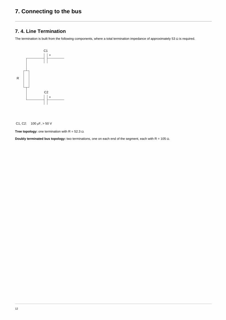
7. 4. Line Termination The termination is built from the following components, where a total termination impedance of approximately 53 Ω is required.
Tree topology: one termination with R = 52.3 Ω.
Doubly terminated bus topology: two terminations, one on each end of the segment, each with R = 105 Ω.
C1, C2: 100 μF, > 50 V
R
C2
C1+
+
12
8. Configuration
8. 1. Service pinThe LonWorks card is equipped with a service pin button.It is used when installing the card as a LonWorks node.Pressing the service pin causes the card to send a message over the network so that it can be identified by the network management tool.
8. 2. ControlNumerous configurations are possible. For more information, refer to the Programming Manual and the Communication parametersmanual.The following configurations are just some of the possibilities available.
b Allowed configurationsIf the drive is only monitored by LonWorks:There is no configuration constraint.
If the drive is controlled by LonWorks:The parameter [Profile] (CHCF) must be configured to [Not separ.] (SIM) or [Separate] (SEP). [Not separ.] (SIM) is the default value.It is not allowed to configure the parameter [Profile] (CHCF) to the value [8 serie] (SE8) or [I/O profile] (IO).If a forbidden configuration is done, the drive will trip to [External fault com.] (EPF2).
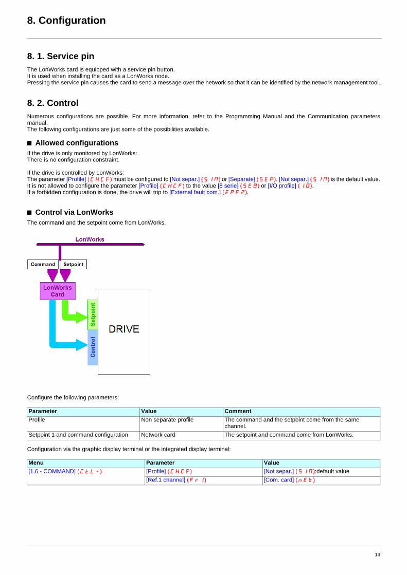
b Control via LonWorksThe command and the setpoint come from LonWorks.
Configure the following parameters:
Configuration via the graphic display terminal or the integrated display terminal:
Parameter Value CommentProfile Non separate profile The command and the setpoint come from the same
channel.Setpoint 1 and command configuration Network card The setpoint and command come from LonWorks.
Menu Parameter Value[1.6 - COMMAND] (CtL-) [Profile] (CHCF) [Not separ.] (SIM):default value
[Ref.1 channel] (Fr1) [Com. card] (nEt)
13

8. Configuration
How to switch to the graphic display terminal:By pressing F4 (T/K) key, the drive will go to local control.The indication in the right high corner is REM when controlled by LonWorks and LOC when controlled by the display terminal.In local mode, commands and setpoint come from the display terminal.
b Control via LonWorks or via the terminalsThe command and the setpoint both come from LonWorks or the terminals. Depending on the configuration, the application function are activated or not.
2 different use cases are described below. The setpoint is switched from LonWorks to the terminals. In the first case, the application functionapplies and not in the second one.
14
8. Configuration
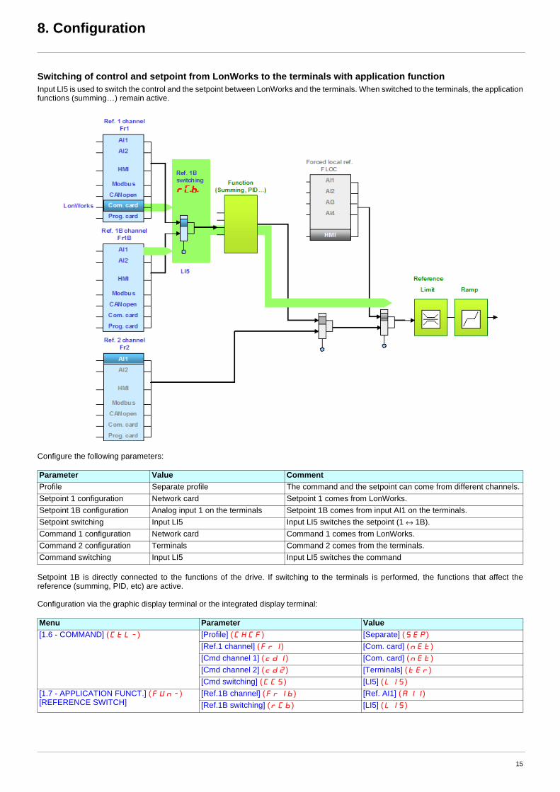
Switching of control and setpoint from LonWorks to the terminals with application functionInput LI5 is used to switch the control and the setpoint between LonWorks and the terminals. When switched to the terminals, the applicationfunctions (summing…) remain active.
Configure the following parameters:
Setpoint 1B is directly connected to the functions of the drive. If switching to the terminals is performed, the functions that affect thereference (summing, PID, etc) are active.
Configuration via the graphic display terminal or the integrated display terminal:
Parameter Value CommentProfile Separate profile The command and the setpoint can come from different channels.Setpoint 1 configuration Network card Setpoint 1 comes from LonWorks.Setpoint 1B configuration Analog input 1 on the terminals Setpoint 1B comes from input AI1 on the terminals.Setpoint switching Input LI5 Input LI5 switches the setpoint (1 ↔ 1B).Command 1 configuration Network card Command 1 comes from LonWorks.Command 2 configuration Terminals Command 2 comes from the terminals.Command switching Input LI5 Input LI5 switches the command
Menu Parameter Value[1.6 - COMMAND] (CtL-) [Profile] (CHCF) [Separate] (SEP)
[Ref.1 channel] (Fr1) [Com. card] (nEt)[Cmd channel 1] (cd1) [Com. card] (nEt)[Cmd channel 2] (cd2) [Terminals] (tEr)[Cmd switching] (CCS) [LI5] (LI5)
[1.7 - APPLICATION FUNCT.] (FUn-)[REFERENCE SWITCH]
[Ref.1B channel] (Fr1b) [Ref. AI1] (AI1)[Ref.1B switching] (rCb) [LI5] (LI5)
15
8. Configuration
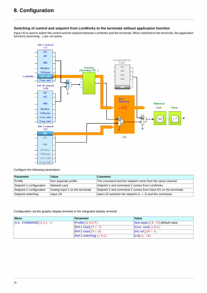
Switching of control and setpoint from LonWorks to the terminals without application functionInput LI5 is used to switch the control and the setpoint between LonWorks and the terminals. When switched to the terminals, the applicationfunctions (summing…) are not active.
Configure the following parameters:
Configuration via the graphic display terminal or the integrated display terminal:
Parameter Value CommentProfile Non separate profile The command and the setpoint come from the same channel.Setpoint 1 configuration Network card Setpoint 1 and command 1 comes from LonWorks.Setpoint 2 configuration Analog input 1 on the terminals Setpoint 2 and command 2 comes from input AI1 on the terminals.Setpoint switching Input LI5 Input LI5 switches the setpoint (1 ↔ 2) and the command.
Menu Parameter Value[1.6 - COMMAND] (CtL-) [Profile] (CHCF) [Not separ.] (SIM):default value
[Ref.1 chan] (Fr1) [Com. card] (nEt)[Ref.2 chan] (Fr2) [AI1 ref.] (AI1)[Ref.2 switching] (rFC) [LI5] (LI5)
16
8. Configuration
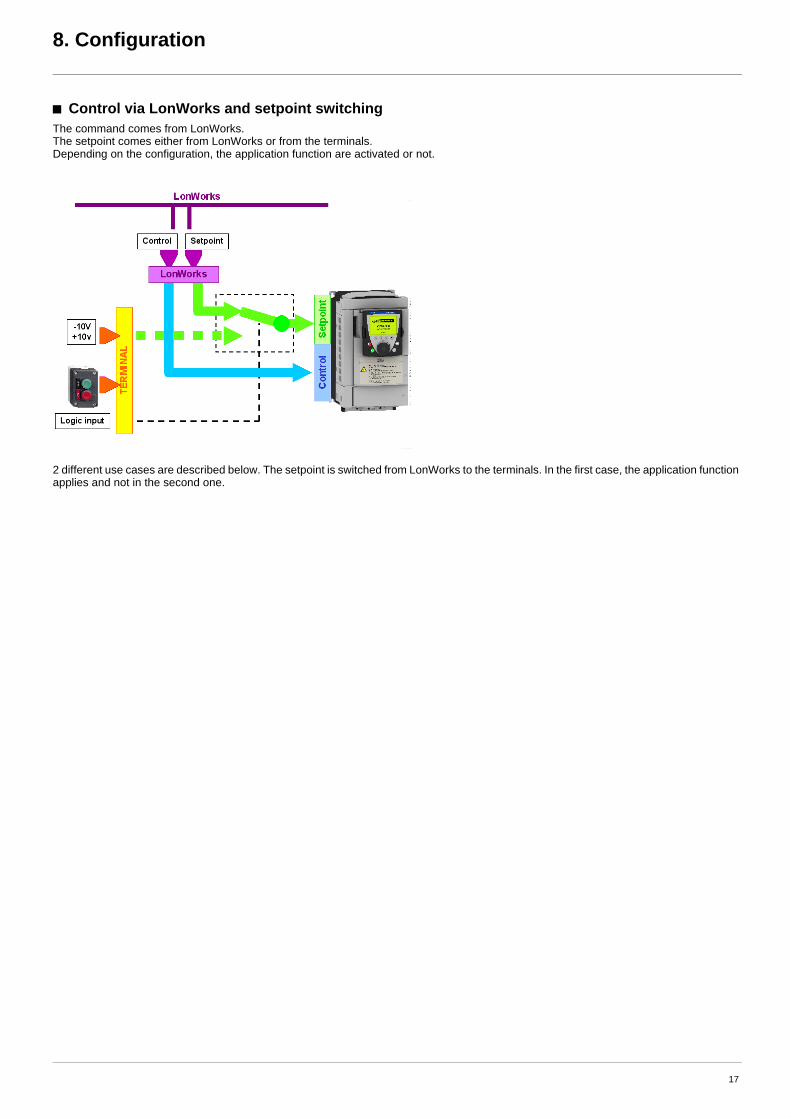
b Control via LonWorks and setpoint switchingThe command comes from LonWorks.The setpoint comes either from LonWorks or from the terminals. Depending on the configuration, the application function are activated or not.
2 different use cases are described below. The setpoint is switched from LonWorks to the terminals. In the first case, the application functionapplies and not in the second one.
17

8. Configuration
Control via LonWorks and switching of the setpoint at the terminals with application functionThe command comes from LonWorks. Input LI5 is used to switch the setpoint between LonWorks and the terminals. When switched to theterminals, the application functions (summing…) remain active.
Configure the following parameters:
Reference 1B is directly connected to the functions of the drive. If switching to the terminals is performed, the functions that affect thereference (summing, PID, etc) are active.
Configuration via the graphic display terminal or the integrated display terminal:
Parameter Value CommentProfile Separate profile The command
and the setpoint can come from different channels.Setpoint 1 configuration Network card Setpoint 1 comes from LonWorks.Setpoint 1B configuration Analog input 1 on the terminals Setpoint 1B comes from input AI1 on the terminals.Setpoint switching Input LI5 Input LI5 switches the reference (1 ↔ 1B).Command 1 configuration Network card Command 1 comes from LonWorks.Command switching Channel 1 Channel 1 is the command channel.
Menu Parameter Value[1.6 - COMMAND] (CtL-) [Profile] (CHCF) [Separate] (SEP)
[Ref.1 channel] (Fr1) [Com. card] (nEt)[Cmd channel 1] (cd1) [Com. card] (nEt)[Cmd switching] (CCS) [ch1 active] (Cd1)
[1.7 - APPLICATION FUNCT.] (FUn-)[REFERENCE SWITCH]
[Ref.1B channel] (Fr1b) [Ref. AI1] (AI1)[Ref.1B switching] (rCb) [LI5] (LI5)
18

8. Configuration
Control via LonWorks and switching of the setpoint at the terminals with application functionThe command comes from LonWorks. Input LI5 is used to switch the setpoint between LonWorks and the terminals. When switched to theterminals, the application functions (summing…) are not active.
Configure the following parameters:
Setpoint 1B is connected to the functions (Summing, etc) that remain active even after switching.
Configuration via the graphic display terminal or the integrated display terminal:
Parameter Value CommentProfile Separate profile The command and the setpoint can come from different channels.Setpoint 1 configuration Network card Setpoint 1 comes from LonWorks.Setpoint 2 configuration Analog input 1 on the terminals Setpoint 2 comes from input AI1 on the terminals.Setpoint switching Input LI5 Input LI5 switches the setpoint (1↔ 2).Command 1 configuration Network card Command 1 comes from LonWorks.Command switching Channel 1 Channel 1 is the command channel.
Menu Parameter Value[1.6 – COMMAND] (CtL-) [Profile] (CHCF) [Separate] (SEP)
[Ref.1 chan] (Fr1) [Com. card] (nEt)[Ref.2 chan] (Fr2) [AI1 ref.] (AI1)[Ref 2 switching] (rFc) [LI5] (LI5)[Cmd channel 1] (Cd1) [Com. card] (nEt)[Cmd switching] (CCS) [ch1 active] (Cd1)
19

8. Configuration
8. 3. Communication scannerYou do not need to read this chapter if you do not intend to use the network variables nviScannerOut1 or nvoScannerIn1.
The network variables communication scanner out 1 (nviScannerOut1) is assigned using the [Scan.Out1 address] (nCA1) parameter. Itis configured using the graphic display terminal via the [1.9 - COMMUNICATION] (COM-) menu, [COM. SCANNER OUTPUT] (OCS-)submenu.
The network variable communication scanner in 1 (nvoScannerIn1) is assigned using the [Scan.IN1 address] (nNA1) parameter. It isconfigured using the graphic display terminal via the [1.9 - COMMUNICATION] (COM-) menu, [COM. SCANNER INPUT] (ICS-)submenu.
Enter the logic address of the parameter (refer to the Communication parameters manual).
If a [Scan.Out1 address] (nCA1) or [Scan.IN1 address] (nNA1) parameter equals zero, the corresponding variable is not used by thedrive.
16 assignment parameters exist in the drive, they described in the tables below. Only [Scan. Out1 address] (nCA1) and [Scan. IN1address] (nMA1) are useful for the LonWorks card.
Example of configuration via the graphic display terminal:8503 is the logical address of PID setpoint and 11980 is the logical address of [PID error].
Note:Any modification to parameters [Scan.Out1 address] (nCA1) or [Scan.IN1 address] (nNA1) must be made with the motor stopped. Themaster controller program should be updated to take account of this modification.
Configuration parameter name Default assignment of the output variable Example of assignment[Scan. Out1 address] (nCA1) Control word (CMd) PID setpoint[Scan. Out2 address] (nCA2) Speed reference (LFrd)
Not used
[Scan. Out3 address] (nCA3)
Not used
[Scan. Out4 address] (nCA4)[Scan. Out5 address] (nCA5)[Scan. Out6 address] (nCA6)[Scan. Out7 address] (nCA7)[Scan. Out8 address] (nCA8)
Configuration parameter name Default assignment of the input variable Example of assignment[Scan. IN1 address] (nMA1) Status word (EtA) [PID error][Scan. IN2 address] (nMA2) Output speed (rFrd)
Not used
[Scan. IN3 address] (nMA3)
Not used
[Scan. IN4 address] (nMA4)[Scan. IN5 address] (nMA5)[Scan. IN6 address] (nMA6)[Scan. IN7 address] (nMA7)[Scan. IN8 address] (nMA8)
RDY NET +0.00Hz 0A RDY NET +0.00Hz 0A
COM. SCANNER INPUT COM. SCANNER OUTPUT
Scan. IN1 address : 8503 Scan. Out1 address : 11980
Scan. IN2 address : 0 Scan. Out2 address : 0
Scan. IN3 address : 0 Scan. Out3 address : 0
Scan. IN4 address : 0 Scan. Out4 address : 0
Scan. IN5 address : 0 Scan. Out5 address : 0
Code Quick Code Quick
Scan. IN6 address : 0 Scan. Out6 address : 0
Scan. IN7 address : 0 Scan. Out7 address : 0
Scan. IN8 address : 0 Scan. Out8 address : 0
20

8. Configuration
8. 4. Communication faultsA LonWorks fault is triggered if the LONMARK card does not receive at least one of the network variables nviDrvSpeedStpt,nviDrvSpeedScale or nviInvSetFreq within a predefined time period (configuration property Receive heartbeat time nciRcvHrtBt, refer to“Network management”, page 51).
The monitoring of the LonWorks communication can be disabled if the configuration property Receive heartbeat time nciRcvHrtBt is set to0.0.
The response of the drive in the event of a LONMARK communication fault can be configured.
The values of the [Network fault mgt] (CLL) parameter, which trigger a [Com. network] (CnF) drive fault, are:
The values of the [Network fault mgt] (CLL) parameter, which do not trigger a drive fault, are:
The fallback speed can be configured via the [Fallback speed] (LFF) parameter in the [1.8 – FAULT MANAGEMENT] (FLt-) menu.
WARNINGIf this function is not properly set up, it may cause an accident.If you configure the configuration property Receive Heartbeat Time (nciRcvHrtBt) to the value 0.0, the drive will not trip in drivecommunication fault [Com. network] (CnF).As soon as the LONWORKS communication comes back, the drive will restart according to the LonWorks control.
This is the default value according to the LONMARK standard.
Failure to follow this instruction can result in death, serious injury or equipment damage.
Configuration can be performed using the graphic display terminal or integrated display terminal using the [Network fault mgt] (CLL) parameter in the [1.8 FAULT MANAGEMENT] (FLt-) menu, [COM. FAULT MANAGEMENT] (CLL-) submenu.
RDY NET +0.00Hz 0A
COM. FAULT MANAGEMENT
Network fault mgt : Freewheel
CANopen fault mgt : Freewheel
Modbus fault mgt : Freewheel
Code Quick
Value Meaning
[Freewheel] (YES) Freewheel stop (factory setting)
[Ramp stop] (rMP) Stop on ramp
[Fast stop] (FSt) Fast stop
[DC injection] (dCI) DC injection stop
Value Meaning
[Ignore] (nO) Fault ignored
[Per STT] (Stt) Stop according to configuration of [Type of stop] (Stt).
[fallback spd] (LFF) Switch to fallback speed, maintained as long as the fault is present and the run command is not disabled.
[Spd maint.] (rLS) The drive maintains the speed at the time the fault occurred, as long as the fault persists and the run command has not been removed.
WARNINGIf this function is not properly set up, it may cause an accident.If you configure the parameter [Network fault mgt] (CLL), to [Ignore] (nO), [Per STT] (Stt), [fallback spd] (LFF) or [Spd maint.] (rLS) thedrive will not trip in drive communication fault [Com. network] (CnF).As soon as the LONWORKS communication comes back, the drive will restart according to the LonWorks control.
Failure to follow this instruction can result in death, serious injury or equipment damage.
21

8. Configuration
8. 5. Monitored parametersIt is possible to select up to 4 parameters to display their values in the [1.2 - MONITORING] menu ([COMMUNICATION MAP] submenu)on the graphic display terminal.
The selection is made via the [6 - MONITORING CONFIG.] menu ([6.3 - COM. MAP CONFIG. ] submenu).
One of the three display formats below can be assigned to each monitored word:
Each parameter [Word 1 add. select] ... [Word 4 add. select] can be used to choose the logic address of the parameter. Select an address of zero to disable the function.
In the example given here, the monitored words are:
• Parameter 1 = Motor current (LCr): logic address 3204; signed decimal format
• Parameter 2 = Motor torque (Otr): logic address 3205; signed decimal format
• Parameter 3 = Last fault occurred (LFt): logic address 7121; hexadecimal format
• Disabled parameter: address 0; default format: hexadecimal format
RDY NET +0.00Hz 0A
6.3 COM. MAP CONFIG.
Word 1 add. select : 3204
FORMAT 1 : Signed
Word 2 add. select : 3205
FORMAT 2 : Signed
Word 3 add. select : 7121
Code Quick
FORMAT 3 : Hex
Word 4 add. select : 0
FORMAT 4 : Hex
Format Range Terminal displayHexadecimal 0000 ... FFFF [Hex]Signed decimal -32 767 ... 32 767 [Signed]Unsigned decimal 0 ... 65 535 [Unsigned]
22
9. Diagnostics
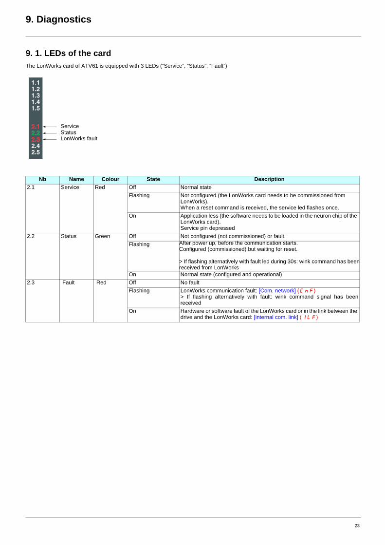
9. 1. LEDs of the cardThe LonWorks card of ATV61 is equipped with 3 LEDs (“Service”, “Status”, “Fault”)
Nb Name Colour State Description2.1 Service Red Off Normal state
Flashing Not configured (the LonWorks card needs to be commissioned from LonWorks).When a reset command is received, the service led flashes once.
On Application less (the software needs to be loaded in the neuron chip of the LonWorks card).Service pin depressed
2.2 Status Green Off Not configured (not commissioned) or fault.Flashing After power up, before the communication starts.
Configured (commissioned) but waiting for reset.
> If flashing alternatively with fault led during 30s: wink command has beenreceived from LonWorks
On Normal state (configured and operational)2.3 Fault Red Off No fault
Flashing LonWorks communication fault: [Com. network] (CnF)> If flashing alternatively with fault: wink command signal has beenreceived
On Hardware or software fault of the LonWorks card or in the link between the drive and the LonWorks card: [internal com. link] (ILF)
1.11.21.31.41.5
2.12.22.32.42.5
ServiceStatusLonWorks fault
23

9. Diagnostics
9. 2. ControlOn the graphic display terminal only, the [1.2 - MONITORING] menu ([COMMUNICATION MAP] submenu) can be used to display controldiagnostic information between the drive and the network:
The LonWorks card receives commands and setpoint from the network. The format of these variables depends on the definition of thenetwork variables nviDrvSpeedSpt, nviInvSetFreq and nviResetFault.The LonWorks card processes these network variables and sends the Control word (cMd) and Frequency setpoint (LFr) to the drive.The parameter (cMd), (LFr) and (EtA) are described in the Communication parameters manual.
RUN NET +50.00Hz 80A
COMMUNICATION MAP
Command Channel : Com. card
Cmd value : 000FHex
Active ref. channel : Com. card
Frequency ref. : 500.0Hz
ETA status word : 8627Hex
Code Quick
W3204 : 53
W3205 : 725
W7132 : 0000Hex
W0 : -----Hex
COM. SCANNER INPUT MAP
COM. SCANNER OUTUT MAP
CMD. WORD IMAGE
FREQ. REF. WORD MAP
Active command channel
Value of control word (cMd) usedto control the drive
(hexadecimal format)
Active reference channel
Value of frequency reference (LFr)(unit 0.1 Hz) used to control the drive
Value of status word (EtA)(hexadecimal format)
Values of the four monitored words selected by the user.The address and display format of these parameters
can be configured in the[6 - MONITORING CONFIG.] menu,
[6.3 - COM. MAP CONFIG.] submenu (see 8. 5. Monitored parameters).
The value of a monitored word is equal to "-----" if:- Monitoring is not activated
(address equal to 0)- The parameter is protected- The parameter is not known (e.g., 3200)
Control word from the LonWorks card (1)[COM. card cmd.] (CMd3)
Frequency setpoint from the LonWorks card[Com. card ref.] (LFr3)
24
9. Diagnostics
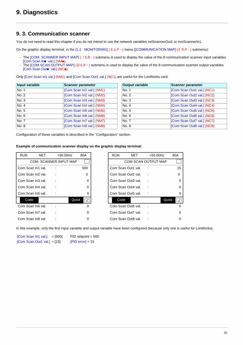
9. 3. Communication scannerYou do not need to read this chapter if you do not intend to use the network variables nviScannerOut1 or nvoScannerIn1.
On the graphic display terminal, in the [1.2 - MONITORING] (SUP-) menu ([COMMUNICATION MAP] (CMM-) submenu):
- The [COM. SCANNER INPUT MAP] (ISA-) submenu is used to display the value of the 8 communication scanner input variables [Com Scan Inp val.] (NMp).
- The [COM SCAN OUTPUT MAP] (OSA-) submenu is used to display the value of the 8 communication scanner output variables [Com Scan Outp val.] (NCp).
Only [Com Scan In1 val.] (NM1) and [Com Scan Out1 val.] (NC1) are useful for the LonWorks card.
Configuration of these variables is described in the "Configuration" section.
Example of communication scanner display on the graphic display terminal:
In this example, only the first input variable and output variable have been configured (because only one is useful for LonWorks).
Input variable Scanner parameter Output variable Scanner parameterNo. 1 [Com Scan In1 val.] (NM1) No. 1 [Com Scan Out1 val.] (NC1)No. 2 [Com Scan In2 val.] (NM2) No. 2 [Com Scan Out2 val.] (NC2)No. 3 [Com Scan In3 val.] (NM3) No. 3 [Com Scan Out3 val.] (NC3)No. 4 [Com Scan In4 val.] (NM4) No. 4 [Com Scan Out4 val.] (NC4)No. 5 [Com Scan In5 val.] (NM5) No. 5 [Com Scan Out5 val.] (NC5)No. 6 [Com Scan In6 val.] (NM6) No. 6 [Com Scan Out6 val.] (NC6)No. 7 [Com Scan In7 val.] (NM7) No. 7 [Com Scan Out7 val.] (NC7)No. 8 [Com Scan In8 val.] (NM8) No. 8 [Com Scan Out8 val.] (NC8)
RUN NET +50.00Hz 80A RUN NET +50.00Hz 80A
COM. SCANNER INPUT MAP COM SCAN OUTPUT MAP
Com Scan In1 val. : 500 Com Scan Out1 val. : 15
Com Scan In2 val. : 0 Com Scan Out2 val. : 0
Com Scan In3 val. : 0 Com Scan Out3 val. : 0
Com Scan In4 val. : 0 Com Scan Out4 val. : 0
Com Scan In5 val. : 0 Com Scan Out5 val. : 0
Code Quick Code Quick
Com Scan In6 val. : 0 Com Scan Out6 val. : 0
Com Scan In7 val. : 0 Com Scan Out7 val. : 0
Com Scan In8 val. : 0 Com Scan Out8 val. : 0
[Com Scan In1 val.] = [500] PID setpoint = 500[Com Scan Out1 val.] = [15] [PID error] = 15
25
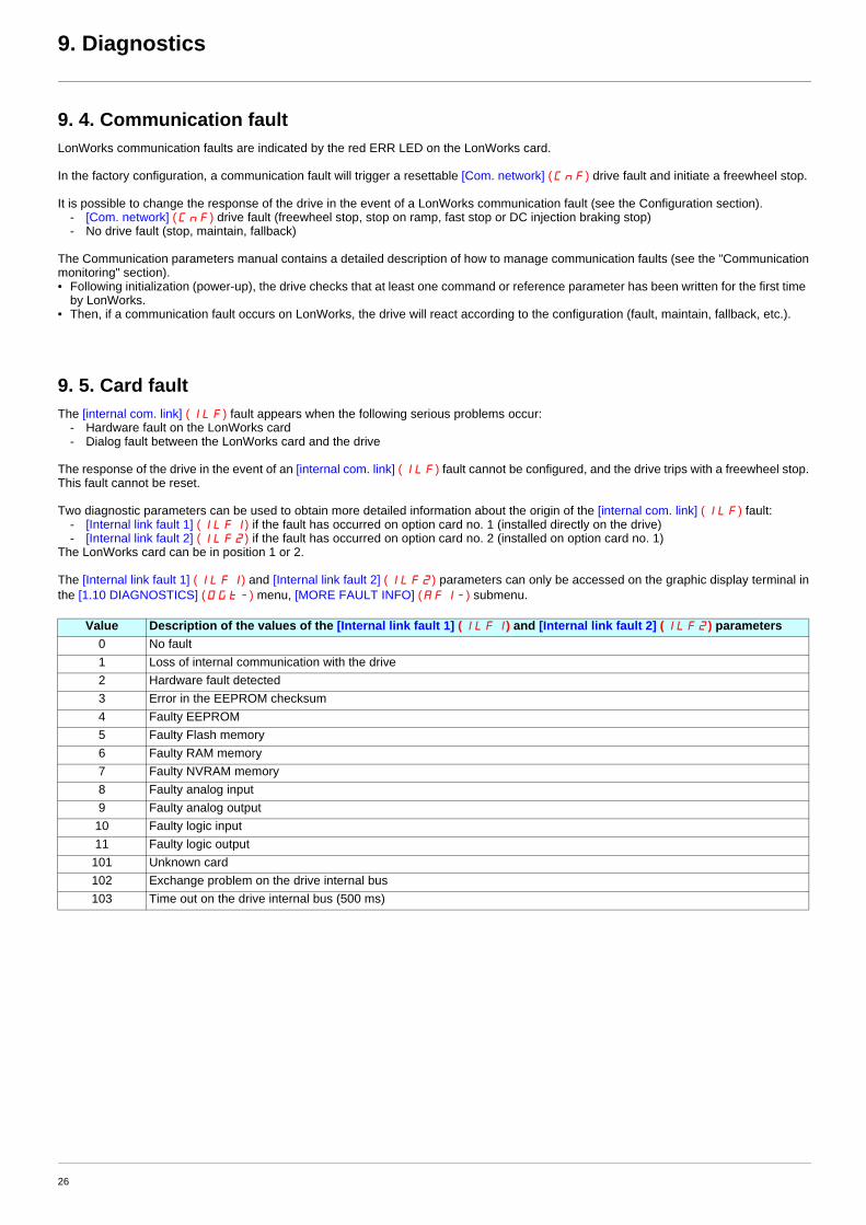
9. Diagnostics
9. 4. Communication faultLonWorks communication faults are indicated by the red ERR LED on the LonWorks card.
In the factory configuration, a communication fault will trigger a resettable [Com. network] (CnF) drive fault and initiate a freewheel stop.
It is possible to change the response of the drive in the event of a LonWorks communication fault (see the Configuration section).- [Com. network] (CnF) drive fault (freewheel stop, stop on ramp, fast stop or DC injection braking stop)- No drive fault (stop, maintain, fallback)
The Communication parameters manual contains a detailed description of how to manage communication faults (see the "Communicationmonitoring" section).• Following initialization (power-up), the drive checks that at least one command or reference parameter has been written for the first time
by LonWorks.• Then, if a communication fault occurs on LonWorks, the drive will react according to the configuration (fault, maintain, fallback, etc.).
9. 5. Card faultThe [internal com. link] (ILF) fault appears when the following serious problems occur:
- Hardware fault on the LonWorks card- Dialog fault between the LonWorks card and the drive
The response of the drive in the event of an [internal com. link] (ILF) fault cannot be configured, and the drive trips with a freewheel stop.This fault cannot be reset.
Two diagnostic parameters can be used to obtain more detailed information about the origin of the [internal com. link] (ILF) fault:- [Internal link fault 1] (ILF1) if the fault has occurred on option card no. 1 (installed directly on the drive)- [Internal link fault 2] (ILF2) if the fault has occurred on option card no. 2 (installed on option card no. 1)
The LonWorks card can be in position 1 or 2.
The [Internal link fault 1] (ILF1) and [Internal link fault 2] (ILF2) parameters can only be accessed on the graphic display terminal inthe [1.10 DIAGNOSTICS] (DGt-) menu, [MORE FAULT INFO] (AFI-) submenu.
Value Description of the values of the [Internal link fault 1] (ILF1) and [Internal link fault 2] (ILF2) parameters0 No fault1 Loss of internal communication with the drive2 Hardware fault detected3 Error in the EEPROM checksum4 Faulty EEPROM5 Faulty Flash memory6 Faulty RAM memory7 Faulty NVRAM memory8 Faulty analog input9 Faulty analog output
10 Faulty logic input11 Faulty logic output101 Unknown card102 Exchange problem on the drive internal bus103 Time out on the drive internal bus (500 ms)
26

10. Functional profile
b Objects supportedThe LonWorks card for ATV61 complies to the LonMark functionnal profile variable Speed Motor Drive (specification 6010-11).
According to this profile 2 objects are supported:
- the node object (specification 0000-20),- the variable speed motor drive object.
b LONMARK Node Object profile
NodeObject
VSDobject
Mandatory Network Variables
Node Object
nviRequest (SNVT_obj_request) nvoStatus (SNVT_obj_status)
27

10. Functional profile
b LONMARK Variable Speed Motor Drive profile
Mandatory Network Variables
Variable Speed Motor Drive
nviDrvSpeedStpt (SNVT_switch)
Optional Network Variables
nviDrvSpeedScale (SNVT_lev_percent)nvoDrvCurnt (SNVT_amp)nvoDrvVolt (SNVT_volt)nvoDrvPwr (SNVT_power_kilo)nvoDrvRunHours (SNVT_time_hour)
Manufacturer Network Variables
Manufacturer Configuration Properties
Input Network Variables
Output Network Variables
nvoDrvSpeed (SNVT_lev_percent)
nviInvSetFreq (SNVT_freq_hz)nviResetFault (SNVT_switch)nviRelay1 (SNVT_switch)nviRelay2 (SNVT_switch)nviDigitalOutput (SNVT_state)nviAnalogOut1 (SNVT_lev_percent)nviEmergOverride (SNVT_hvac_emerg)nviParamCmd (SNVT_preset)nviScannerOut1 (SNVT_count_inc)
nvoDrvFeedback (SNVT_switch)nvoInvOutFreq (SNVT_freq_hz)nvoStatusWord (SNVT_state)nvoDrvAlarm (SNVT_switch)nvoAlarmWord (SNVT_state)nvoDrvEnergy (SNVT_elec_kwh_l)nvoDrvThermal (SNVT_lev_percent)nvoMotorThermal (SNVT_lev_percent)nvoTorque (SNVT_lev_percent)nvoDigitalIn4 (SNVT_switch)nvoDigitalIn5 (SNVT_switch)nvoDigitalInput (SNVT_state)nvoAnalogIn1 (SNVT_lev_percent)nvoAnalogIn2 (SNVT_lev_percent)nvoEmergStatus (SNVT_hvac_emerg)nvoParamResp (SNVT_preset)nvoTypeVer (SNVT_str_asc)nvoScannerIn1 (SNVT_count_inc)
Mandatory Network Variables
nciMaxSpeed (SNVT_lev_percent)nciMinSpeed (SNVT_lev_percent)nciNmlSpeed (SNVT_rpm)nciNmlFreq (SNVT_freq_hz)nciRampUpTm (SNVT_time_sec)nciRampDownTm (SNVT_time_sec)nciSndHrtBt (SNVT_time_sec)
nciPwUpOutTm (SNVT_time_sec)
Optional Configuration Properties
nciLocation (SNVT_str_asc)nciDrvSpeedScale (SNVT_lev_percent)nciRcvHrtBt (SNVT_time_sec)nciMinOutTm (SNVT_time_sec)
28

11. Network variables and configuration properties
11. 1. List of network variables and configuration propertiesCommands and setpoints
Status and output velocity
Alarms
Measurements
Monitoring of digital inputs
Monitoring of analog inputs
Control of digital outputs
Control of analog outputs
Name SNVT Definition DescriptionnviDrvSpeedStpt SNVT_switch Drive Speed Setpoint Variable Speed Motor Drive object (M)nviDrvSpeedScale SNVT_lev_percent Drive Speed Setpoint Scaling Variable Speed Motor Drive object (O)nciDrvSpeedScale SNVT_lev_percent Default Value for nviDrvSpeedScale Variable Speed Motor Drive object (O)nviInvSetFreq SNVT_freq_hz Frequency setpoint Manufacturer specificnviResetFault SNVT_switch Fault reset command Manufacturer specificnviRequest SNVT_obj_request Object Request Node object (M)
Name SNVT Definition DescriptionnvoDrvSpeed SNVT_lev_percent Drive Speed Feedback Variable Speed Motor Drive object (M)nvoDrvFeedback SNVT_switch Drive velocity feedback Manufacturer specificnvoInvOutFreq SNVT_freq_hz Output frequency Manufacturer specificnvoStatusWord SNVT_state Drive status Manufacturer specificnvoStatus SNVT_obj_status Object Status Node object (M)
Name SNVT Definition DescriptionnvoDrvAlarm SNVT_switch Alarm code Manufacturer specificnvoAlarmWord SNVT_state Alarm status Manufacturer specific
Name SNVT Definition DescriptionnvoDrvCurnt SNVT_amp Drive Output Current Variable Speed Motor Drive object (O)nvoDrvVolt SNVT_volt Drive Output Voltage Variable Speed Motor Drive object (O)nvoDrvPwr SNVT_power_kilo Drive Output Power Variable Speed Motor Drive object (O)nvoDrvRunHours SNVT_time_hour Drive Total Running Hours Variable Speed Motor Drive object (O)nvoDrvEnergy SNVT_elec_kwh_l Energy consumption Manufacturer specificnvoDrvThermal SNVT_lev_percent Drive thermal state Manufacturer specificnvoMotorThermal SNVT_lev_percent Motor thermal state Manufacturer specificnvoTorque SNVT_lev_percent Torque Manufacturer specific
Name SNVT Definition DescriptionnvoDigitalIn4 SNVT_switch State of digital input 4 Manufacturer specificnvoDigitalIn5 SNVT_switch State of digital input 5 Manufacturer specificnvoDigitalInput SNVT_state State of digital inputs Manufacturer specific
Name SNVT Definition DescriptionnvoAnalogIn1 SNVT_lev_percent Value of analog input 1 Manufacturer specificnvoAnalogIn2 SNVT_lev_percent Value of analog input 2 Manufacturer specific
Name SNVT Definition DescriptionnviRelay1 SNVT_switch Command of relay 1 Manufacturer specificnviRelay2 SNVT_switch Command of relay 2 Manufacturer specificnviDigitalOutput SNVT_state Command of relays and digital outputs Manufacturer specific
Name SNVT Definition DescriptionnviAnalogOut1 SNVT_lev_percent Command of analog output 1 Manufacturer specific
29

11. Network variables and configuration properties
Emergency
Adjustment
Parameter access
Identification
Network management
Scanner
Name SNVT Definition DescriptionnviEmergOverride SNVT_hvac_emerg Emergency command Manufacturer specificnvoEmergStatus SNVT_hvac_emerg Emergency feedback Manufacturer specific
Name SNVT Definition DescriptionnciMaxSpeed SNVT_lev_percent Maximum Motor Speed Variable Speed Motor Drive object (M)nciMinSpeed SNVT_lev_percent Minimum Motor Speed Variable Speed Motor Drive object (M)nciNmlSpeed SNVT_rpm Nominal Motor Speed in RPM Variable Speed Motor Drive object (M)nciNmlFreq SNVT_freq_hz Nominal Motor Frequency Variable Speed Motor Drive object (M)nciRampUpTm SNVT_time_sec Minimum Ramp Up Time Variable Speed Motor Drive object (M)nciRampDownTm SNVT_time_sec Minimum Ramp Down Time Variable Speed Motor Drive object (M)
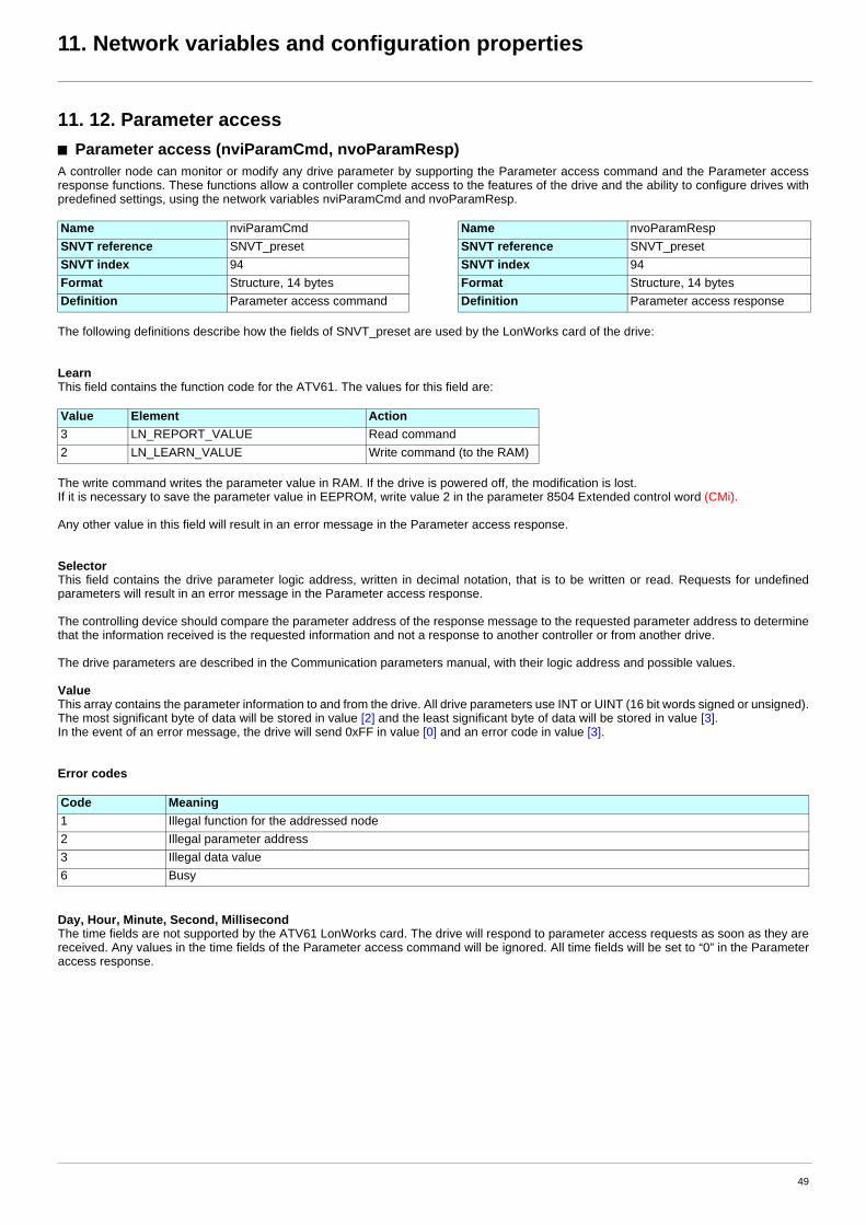
Name SNVT Definition DescriptionnviParamCmd SNVT_preset Parameter access command Manufacturer specificnvoParamResp SNVT_preset Parameter access response Manufacturer specific
Name SNVT Definition DescriptionnciLocation SNVT_str_asc Location Label Variable Speed Motor Drive object (O)nvoTypeVer SNVT_str_asc Drive identification Manufacturer specific
Name SNVT Definition DescriptionnciSndHrtBt SNVT_time_sec Send Heartbeat Time Variable Speed Motor Drive object (M)nciRcvHrtBt SNVT_time_sec Receive Heartbeat Time Variable Speed Motor Drive object (O)nciMinOutTm SNVT_time_sec Minimum Send Time Variable Speed Motor Drive object (O)nciPwUpOutTm SNVT_time_sec Initial inhibition time Manufacturer specific
Name SNVT Definition DescriptionnviScannerOut1 SNVT_count_inc Communication scanner out 1 (nC1) Manufacturer specificnvoScannerIn1 SNVT_count_inc Communication scanner in 1 (nM1) Manufacturer specific
30
11. Network variables and configuration properties
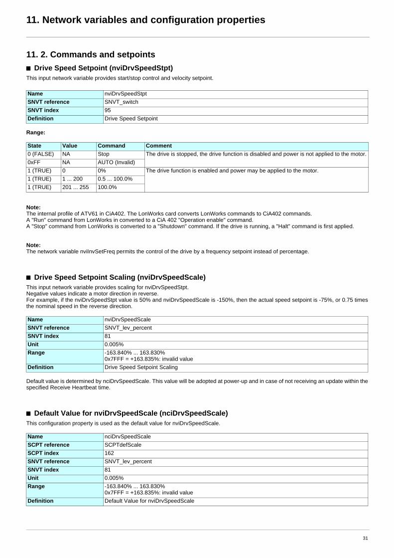
11. 2. Commands and setpointsb Drive Speed Setpoint (nviDrvSpeedStpt)This input network variable provides start/stop control and velocity setpoint.
Range:
Note:The internal profile of ATV61 in CiA402. The LonWorks card converts LonWorks commands to CiA402 commands.A "Run" command from LonWorks in converted to a CiA 402 "Operation enable" command.A "Stop" command from LonWorks is converted to a "Shutdown" command. If the drive is running, a "Halt" command is first applied.
Note:The network variable nviInvSetFreq permits the control of the drive by a frequency setpoint instead of percentage.
b Drive Speed Setpoint Scaling (nviDrvSpeedScale)This input network variable provides scaling for nviDrvSpeedStpt.Negative values indicate a motor direction in reverse.For example, if the nviDrvSpeedStpt value is 50% and nviDrvSpeedScale is -150%, then the actual speed setpoint is -75%, or 0.75 timesthe nominal speed in the reverse direction.
Default value is determined by nciDrvSpeedScale. This value will be adopted at power-up and in case of not receiving an update within thespecified Receive Heartbeat time.
b Default Value for nviDrvSpeedScale (nciDrvSpeedScale)This configuration property is used as the default value for nviDrvSpeedScale.
Name nviDrvSpeedStptSNVT reference SNVT_switchSNVT index 95Definition Drive Speed Setpoint
State Value Command Comment0 (FALSE) NA Stop The drive is stopped, the drive function is disabled and power is not applied to the motor.0xFF NA AUTO (Invalid)1 (TRUE) 0 0% The drive function is enabled and power may be applied to the motor.1 (TRUE) 1 ... 200 0.5 ... 100.0%1 (TRUE) 201 ... 255 100.0%
Name nviDrvSpeedScaleSNVT reference SNVT_lev_percentSNVT index 81Unit 0.005%Range -163.840% ... 163.830%
0x7FFF = +163.835%: invalid valueDefinition Drive Speed Setpoint Scaling
Name nciDrvSpeedScaleSCPT reference SCPTdefScaleSCPT index 162SNVT reference SNVT_lev_percentSNVT index 81Unit 0.005%Range -163.840% ... 163.830%
0x7FFF = +163.835%: invalid valueDefinition Default Value for nviDrvSpeedScale
31
11. Network variables and configuration properties
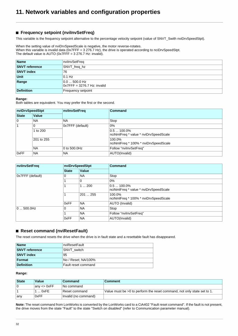
b Frequency setpoint (nviInvSetFreq)This variable is the frequency setpoint alternative to the percentage velocity setpoint (value of SNVT_Swith nviDrvSpeedStpt).
When the setting value of nviDrvSpeedScale is negative, the motor reverse-rotates.When this variable is invalid data (0x7FFF = 3 276.7 Hz), the drive is operated according to nciDrvSpeedStpt.The default value is AUTO (0x7FFF = 3 276.7 Hz: invalid).
Range:Both tables are equivalent. You may prefer the first or the second.
b Reset command (nviResetFault)The reset command resets the drive when the drive is in fault state and a resettable fault has disappeared.
Range:
Note: The reset command from LonWorks is converted by the LonWorks card to a CiA402 "Fault reset command". If the fault is not present,the drive moves from the state "Fault" to the state "Switch on disabled" (refer to Communication parameter manual).
Name nviInvSetFreqSNVT reference SNVT_freq_hzSNVT index 76Unit 0.1 HzRange 0.0 ... 500.0 Hz
0x7FFF = 3276.7 Hz: invalidDefinition Frequency setpoint
nviDrvSpeedStpt nviInvSetFreq CommandState Value0 NA NA Stop1 0 0x7FFF (default) 0%
1 to 200 0.5 ... 100.0%nciNmlFreq * value * nviDrvSpeedScale
201 to 255 100.0%nciNmlFreq * 100% * nviDrvSpeedScale
NA 0 to 500.0Hz Follow “nviInvSetFreq"0xFF NA NA AUTO(Invalid)
nviInvSetFreq nviDrvSpeedStpt CommandState Value
0x7FFF (default) 0 NA Stop1 0 0%1 1 ... 200 0.5 ... 100.0%
nciNmlFreq * value * nviDrvSpeedScale1 201 ... 255 100.0%
nciNmlFreq * 100% * nviDrvSpeedScale0xFF NA AUTO (Invalid)
0 ... 500.0Hz 0 NA Stop1 NA Follow “nviInvSetFreq"0xFF NA AUTO(Invalid)
Name nviResetFaultSNVT reference SNVT_switchSNVT index 95Format No / Reset; NA/100%Definition Fault reset command
State Value Command Comment0 any <> 0xFF No command1 1 ... 0xFE Reset command Value must be >0 to perform the reset command, not only state set to 1.any 0xFF Invalid (no command)
32

11. Network variables and configuration properties
b Object request (nviRequest)This input network variable provides the mechanism to request an operation or a mode for a functional block within the drive.
Name nviRequestSNVT reference SNVT_obj_request SNVT index 92Definition Object request
Member name Value Descriptionobject_id Stores the object ID.
0 RQ_NORMAL If the specified functional block was in the disabled or overridden state, this request cancels that state, and returns the functional block to normal operation. If the functional block was already in the normal state, a request to enter the normal state is not an error. After device reset, the state of functional blocks on the device is application-specific.(Mandatory for LonMark Node Object)
1 RQ_DISABLED Makes the drive object invalid and brings the motor to a controlled stop.(Mandatory for LonMark Variable Speed Motor Drive profile)
2 RQ_UPDATE_STATUS Request the object status (nvoStatus) to be updated.(Mandatory for LonMark Node Object)
5 RQ_REPORT_MASK Changes to "1".bit (invalid_id, invalid_request, disabled, comm_failure, in_alarm, report_mask) supported by object status (nvoStatus) (Mandatory for LonMark Node Object)
7 RQ_ENABLE Makes the drive object valid.(Mandatory for LonMark Variable Speed Motor Drive profile)
9 RQ_CLEAR_STATUS Clears all bits of the object status (nvoStatus) to "0".10 RQ_CLEAR_ALARM Fault reset command.
Clears to "0" in_alarm bit of object status (nvoStatus).(Mandatory for LonMark Variable Speed Motor Drive profile)
3 RQ_SELF_TEST Not supported.4 RQ_UPDATE_ALARM Not supported.6 RQ_OVERRIDE Not supported.8 RQ_RMV_OVERRIDE Not supported.11 RQ_ALARM_NOTIFY_ENAB
LEDNot supported.
12 RQ_ALARM_NOTIFY_DISABLED
Not supported.
13 RQ_MANUAL_CTRL Not supported.14 RQ_REMOTE_CTRL Not supported.15 RQ_PROGRAM Not supported.16 RQ_CLEAR_RESET Not supported.17 RQ_RESET Not supported.255 FF RQ_NUL Nothing is done.
33

11. Network variables and configuration properties
11. 3. Status and output velocityb Drive Speed Feedback (nvoDrvSpeed)This output network variable provides the speed of the drive as a percentage of the nominal speed.
This value is transmitted immediately when its value has changed significantly.Additionally, this network variable will also be transmitted as a heartbeat output on a regular basis as specified by the Maximum Send Time(nciSndHrtBt) configuration value.
b Drive Velocity feedback (nvoDrvFeedback)This variable monitors Stopped / Running status of the drive and the output velocity of as a percentage of the nominal speed of the drive(unit = 0.5%). It is the output image of nviDrvSpeedStpt.
b Output frequency (nvoInvOutFreq)This variable monitors the output velocity (0.1 Hz unit) of the drive.
Name nvoDrvSpeedSNVT reference SNVT_lev_percentSNVT index 81Unit 0.005%Range -163.840% to 163.830%
0x7FFF = +163.835%: invalidDefinition Drive Speed Feedback
Name nvoDrvFeedbackSNVT reference SNVT_switchSNVT index 95Format Stopped / Running; Actual speedUnit of value 0.5%Range of value 0 ... 127.5%Definition Drive velocity feedback
State Description0 (FALSE) Stopped1 (TRUE) Running
Value Description0... 200 0.0 ... 100.0%201 ... 255 100.5 ... 127.5%
Name nvoInvOutFreqSNVT reference SNVT_freq_hzSNVT index 76Unit 0.1HzDefinition Output frequency
34

11. Network variables and configuration properties
b Drive status (nvoStatusWord)This variable monitors the status of the drive by a bit field.
Name nvoStatusWordSNVT reference SNVT_stateSNVT index 83Definition Drive status
Bit nb Description Link to ATV61 internal parameter0 Fault
0 : No fault1 : Fault
Statusword (8603 = 16#219B, ETA)bit 3
1 Warning0 : No warning1 : Warning
Statusword (8603 = 16#219B, ETA)bit 7
2 Running0 : Stopped1 : Running
Status word 1 (8602 = 16#219B)bit 2
3 Rotation0 : Forward1 : Reverse
Statusword (8603 = 16#219B, ETA)bit 15
4 Ready0 : Forward1 : Reverse
Statusword (8603 = 16#219B, ETA)bit 1
5 Command from the network0 : Not from the network1 : From the network
Active command channel (8442 = 16#20FA, CCC)bit 9
6 Setpoint from the network0 : Not from the network1 : From the network
Active setpoint channel (8441 = 16#20F9, CRC)bit 9
7 At setpoint0 : Setpoint not reached (accelerating or decelerating)1 : Setpoint reached
Statusword (8603 = 16#219B, ETA)bit 10
8 Reserved9 Reserved10 Reserved11 Reserved12 Reserved13 Reserved14 Reserved15 Reserved
35

11. Network variables and configuration properties
b Object Status (nvoStatus)This output network variable indicates various status within the drive.
Name nvoStatusSNVT reference SNVT_obj_statusSNVT index 93Definition Object Status
Member name Descriptionobject_id Returns the value written to object_id of object request (nviRequest).
(Mandatory for LonMark Node Object)invalid_id 1 means requested ID is not implemented in the drive.
(Mandatory for LonMark Node Object)invalid_request 1 means request is not implemented in the drive.disabled 1 means object disabled.out_of_limits Not supported.open_circuit Not supported.out_of_service Not supported.mechanical fault Not supported.feedback_failure Not supported.over_range Not supported.under_range Not supported.electrical_fault Not supported.unable_to_measure Not supported.comm_failure 1 reports the [internal com. link] (ILF) fault.fail_self_test Not supported.self_test_in_progress Not supported.locked_out Not supported.manual_control Not supported.in_alarm 1 means the drive is in fault or in alarm condition.in_override Not supported.report_mask 1 means nvoStatus is an event mask.
When RQ_REPORT_MASK is required by nvi_request, nvoStatus reports as "1" the supported status bit (invalid_id, invalid_request, disabled, comm_failure, in_alarm, report_mask).(Mandatory for LonMark Node Object)
programming_mode Not supported.programming_fail Not supported.alarm_notify_disabled Not supported.reset_complete Not supported.
36
11. Network variables and configuration properties
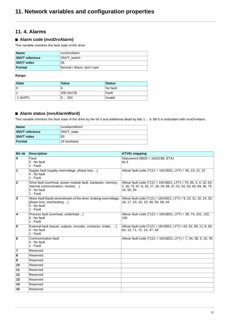
11. 4. Alarmsb Alarm code (nvoDrvAlarm)This variable monitors the fault state of the drive.
Range:
b Alarm status (nvoAlarmWord)This variable monitors the fault state of the drive by the bit 0 and additional detail by bits 1 ... 6. Bit 0 is redundant with nvoDrvAlarm.
Name nvoDrvAlarmSNVT reference SNVT_switchSNVT index 95Format Normal / Alarm; don’t care
State Value Status0 0 No fault1 200 (0xC8) Fault-1 (0xFF) 0 ... 200 Invalid
Name nvoAlarmWordSNVT reference SNVT_stateSNVT index 83Format 16 booleans
Bit nb Description ATV61 mapping0 Fault
0 : No fault1 : Fault
Statusword (8603 = 16#219B, ETA)bit 3
1 Supply fault (supply overvoltage, phase loss ...)0 : No fault1 : Fault
Altivar fault code (7121 = 16#1BD1, LFT) = 40, 19, 21, 22
2 Drive fault (overheat, power module fault, hardware, memory, internal communication, resistor ...)0 : No fault1 : Fault
Altivar fault code (7121 = 16#1BD1, LFT) = 70, 65, 3, 4, 10, 63, 2, 30, 73, 67, 6, 26, 27, 28, 29, 68, 37, 51, 52, 53, 60, 69, 46, 75, 16, 55, 54
3 Motor fault (faults downstream of the drive: braking overvoltage, phase loss, overheating ...)0 : No fault1 : Fault
Altivar fault code (7121 = 16#1BD1, LFT) = 9, 23, 31, 32, 24, 25, 18, 17, 20, 33, 15, 48, 50, 56, 44
4 Process fault (overload, underload ...)0 : No fault1 : Fault
Altivar fault code (7121 = 16#1BD1, LFT) = 39, 74, 101, 102, 100
5 External fault (inputs, outputs, encoder, contactor, brake, ...)0 : No fault1 : Fault
Altivar fault code (7121 = 16#1BD1, LFT) = 62, 61, 58, 11, 8, 59, 64, 13, 71, 72, 14, 47, 49
6 Communication fault0 : No fault1 : Fault
Altivar fault code (7121 = 16#1BD1, LFT) = 7, 34, 38, 5, 42, 45
7 Reserved8 Reserved9 Reserved10 Reserved11 Reserved12 Reserved13 Reserved14 Reserved15 Reserved
37

11. Network variables and configuration properties
11. 5. Measurementsb Drive Output Current (nvoDrvCurnt)This output network variable provides the drive output current (0,1 A).
This value is transmitted immediately when its value has changed significantly.Additionally, this network variable will also be transmitted as a heartbeat output on a regular basis as specified by the Maximum Send Time(nciSndHrtBt) configuration value.
This value will be updated no faster than the Minimum Send Time (nciMinOutTm) configuration value.
b Drive Output Voltage (nvoDrvVolt)This output network variable provides the drive output voltage (V).
This value is transmitted immediately when its value has changed significantly.Additionally, this network variable will also be transmitted as a heartbeat output on a regular basis as specified by the Maximum Send Time(nciSndHrtBt) configuration value.
This value will be updated no faster than the Minimum Send Time (nciMinOutTm) configuration value.
b Drive Output Power (nvoDrvPwr)This output network variable provides the drive power (0.1 kW).
This value is transmitted immediately when its value has changed significantly.Additionally, this network variable may also be transmitted as a heartbeat output on a regular as specified by the Maximum Send Time(nciSndHrtBt) configuration value.
This value will be updated no faster than the Minimum Send Time (nciMinOutTm)configuration value.
Name nvoDrvCurntSNVT reference SNVT_ampSNVT index 1Unit 0.1 ARange 0 ... 3 276.6
0x7FFF = +3 276.7: invalidDefinition Drive Output Current
Name nvoDrvVoltSNVT reference SNVT_voltSNVT index 44Unit VRange 0 ... 700 V
0x7FFF = +3 276.7 V:invalidDefinition Drive Output Voltage
Name nvoDrvPwrSNVT reference SNVT_power_kiloSNVT index 28Unit 0.1 kWRange 0 ... 6 553.4 kW
0xFFFF = 6 553.5 kW: invalidDefinition Drive Output Power
38
11. Network variables and configuration properties
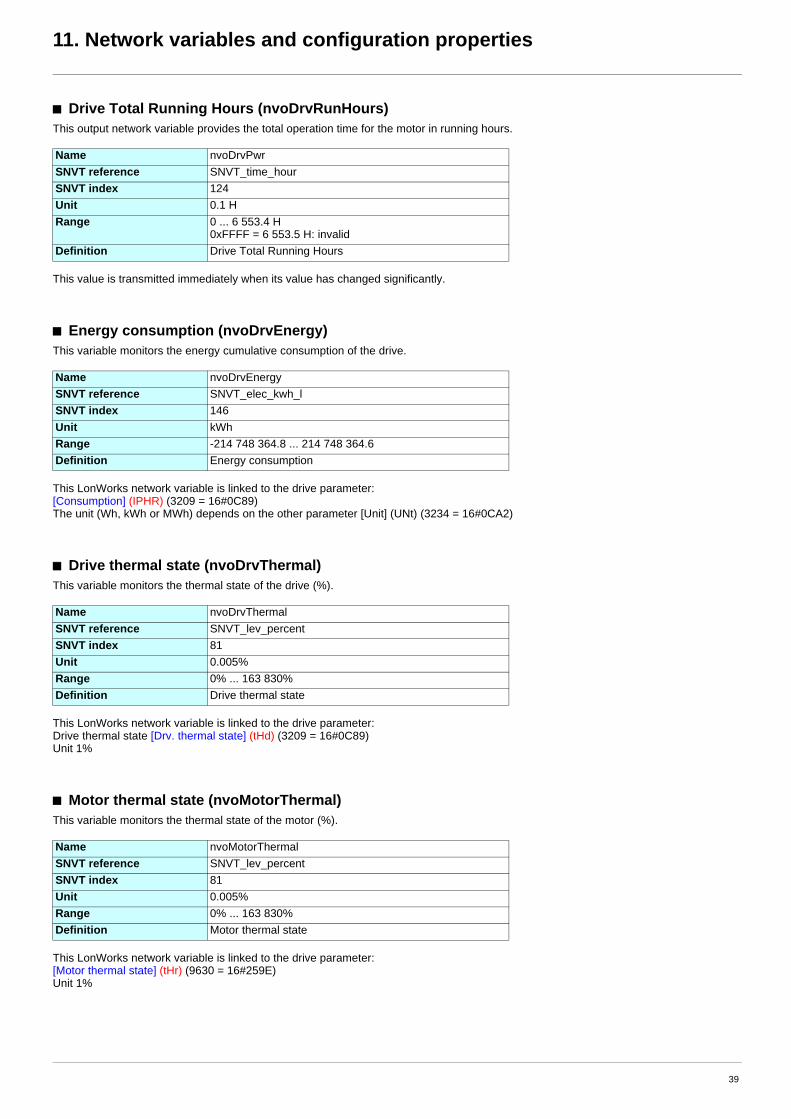
b Drive Total Running Hours (nvoDrvRunHours)This output network variable provides the total operation time for the motor in running hours.
This value is transmitted immediately when its value has changed significantly.
b Energy consumption (nvoDrvEnergy)This variable monitors the energy cumulative consumption of the drive.
This LonWorks network variable is linked to the drive parameter:[Consumption] (IPHR) (3209 = 16#0C89)The unit (Wh, kWh or MWh) depends on the other parameter [Unit] (UNt) (3234 = 16#0CA2)
b Drive thermal state (nvoDrvThermal)This variable monitors the thermal state of the drive (%).
This LonWorks network variable is linked to the drive parameter:Drive thermal state [Drv. thermal state] (tHd) (3209 = 16#0C89)Unit 1%
b Motor thermal state (nvoMotorThermal)This variable monitors the thermal state of the motor (%).
This LonWorks network variable is linked to the drive parameter:[Motor thermal state] (tHr) (9630 = 16#259E)Unit 1%
Name nvoDrvPwrSNVT reference SNVT_time_hourSNVT index 124Unit 0.1 HRange 0 ... 6 553.4 H
0xFFFF = 6 553.5 H: invalidDefinition Drive Total Running Hours
Name nvoDrvEnergySNVT reference SNVT_elec_kwh_lSNVT index 146Unit kWhRange -214 748 364.8 ... 214 748 364.6Definition Energy consumption
Name nvoDrvThermalSNVT reference SNVT_lev_percentSNVT index 81Unit 0.005%Range 0% ... 163 830%Definition Drive thermal state
Name nvoMotorThermalSNVT reference SNVT_lev_percentSNVT index 81Unit 0.005%Range 0% ... 163 830%Definition Motor thermal state
39

11. Network variables and configuration properties
b Torque actual value (nvoTorque)This variable monitors the motor torque.The unit is 0.005% of "Nominal motor torque". The "Nominal motor torque" is not accessible as a drive parameter. It is the result of the othercharacteristics.
This LonWorks network variable is linked to the drive parameter:Output torque [Motor torque] (Otr) (3205 = 16#0C85)Unit 0.01% of Nominal motor torque.
Name nvoTorqueSNVT reference SNVT_lev_percentSNVT index 81Unit 0.005% of Nominal motor torqueRange 0% ... 163 830%
40

11. Network variables and configuration properties
11. 6. Monitoring of digital inputsb Monitoring of digital input 4 (nvoDigitalIn4)This variable monitors the value of digital input 4.
This LonWorks network variable is linked to the drive parameter:Logic input map (IL1r) (5202 = 16#1452) bit 3.
b Monitoring of digital input 5 (nvoDigitalIn5)This variable monitors the value of digital input 5.
This LonWorks network variable is linked to the drive parameter:Logic input map (IL1r) (5202 = 16#1452) bit 4.
b Monitoring of drive digital inputs (nvoDigitalInput)This variable monitors the value of the digital inputs of the drive in a bit field.
This LonWorks network variable is linked to the drive parameter:Logic input map (IL1r) (5202 = 16#1452)
Name nvoDigitalIn4SNVT reference SNVT_switchSNVT index 95Definition Value of the digital input 4
Name nvoDigitalIn5SNVT reference SNVT_switchSNVT index 95Definition Value of the digital input 5
Name nvoDigitalInputSNVT reference SNVT_stateSNVT index 83Format 16 booleansDefinition Value of the digital inputs
Bit nb Terminal name Bit nb Terminal name0 LI1 8 LI9 (with logic I/O card VW3A3201)1 LI2 9 LI10 (with logic I/O card VW3A3201)2 LI3 10 LI11 (with extended I/O card VW3A3202)3 LI4 11 LI12 (with extended I/O card VW3A3202)4 LI5 12 LI13 (with extended I/O card VW3A3202)5 LI6 13 LI14 (with extended I/O card VW3A3202)6 LI7 (with logic I/O card VW3A3201) 14 not used7 LI8 (with logic I/O card VW3A3201) 15 not used
41
11. Network variables and configuration properties
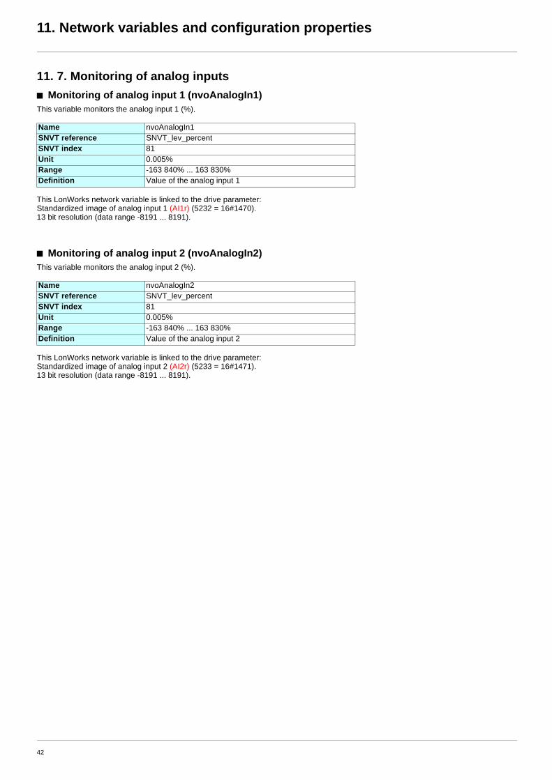
11. 7. Monitoring of analog inputsb Monitoring of analog input 1 (nvoAnalogIn1)This variable monitors the analog input 1 (%).
This LonWorks network variable is linked to the drive parameter:Standardized image of analog input 1 (AI1r) (5232 = 16#1470).13 bit resolution (data range -8191 ... 8191).
b Monitoring of analog input 2 (nvoAnalogIn2)This variable monitors the analog input 2 (%).
This LonWorks network variable is linked to the drive parameter:Standardized image of analog input 2 (AI2r) (5233 = 16#1471).13 bit resolution (data range -8191 ... 8191).
Name nvoAnalogIn1SNVT reference SNVT_lev_percentSNVT index 81Unit 0.005%Range -163 840% ... 163 830%Definition Value of the analog input 1
Name nvoAnalogIn2SNVT reference SNVT_lev_percentSNVT index 81Unit 0.005%Range -163 840% ... 163 830%Definition Value of the analog input 2
42

11. Network variables and configuration properties
11. 8. Control of digital outputsb Control of relay 1 (nviRelay1)This variable enables the command of relay 1 of the drive if it is not assigned.
This LonWorks network variable is linked to the drive parameter:Logic input map (0L1r) (5212 = 16#145C) bit 0.
b Control of relay 2 (nviRelay2)This variable enables the command of relay 1 of the drive if it is not assigned.
This LonWorks network variable is linked to the drive parameter:Logic output map (0L1r) (5212 = 16#145C) bit 1.
b Control relays and digital outputs (nviDigitalOutput)This variable enables the command of the relays and digital outputs of the drive if it is they are not assigned.
This LonWorks network variable is linked to the drive parameter:Logic output map (0L1r) (5212 = 16#145C).
If nviRelay1 and nviDigitalOutput are used at the same time, a logical OR is applied (see table below).If nviRelay2 and nviDigitalOutput are used at the same time, a logical OR is applied (see table below).
Name nviRelay1SNVT reference SNVT_switchSNVT index 95Definition Command of relay 1
Name nviRelay2SNVT reference SNVT_switchSNVT index 95Definition Command of relay 2
Name nviDigitalOutputSNVT reference SNVT_stateSNVT index 83Format 16 booleansDefinition Command of relays and digital outputs
Bit nb Terminal name Bit nb Terminal name0 R1 8 LO1 (with logic I/O card VW3A3201)1 R2 9 LO2 (with logic I/O card VW3A3201)2 R3 (with logic I/O card VW3A3201) 10 LO3 (with extended I/O card VW3A3202)3 R4 (with extended I/O card VW3A3202) 11 LO4 (with extended I/O card VW3A3202)4 not used 12 not used5 not used 13 not used6 not used 14 not used7 not used 15 not used
nviRelay1 nviDigitalOutput R1 nviRelay2 nviDigitalOutput R20 0x0000 0 0 0x0000 01 0x0000 1 1 0x0000 10 0x0001 1 0 0x0001 11 0x0001 1 1 0x0001 1
43

11. Network variables and configuration properties
11. 9. Control of analog outputsb Control of analog output 1 (nviAnalogOut1)This variable enables the command of the analog output 1 (%) if it not assigned.
This LonWorks network variable is linked to the drive parameter:Standardized image of analog output 1 (AO1r) (5261 = 16#148D).13 bit resolution (data range -8191 ... 8191).
Name nviAnalogOut1SNVT reference SNVT_lev_percentSNVT index 81Unit 0.005%Range -163 840% ... 163 830%
44

11. Network variables and configuration properties
11. 10. Emergencyb Emergency command (nviEmergOverride)This variable produces an emergency stop of the drive.The emergency state disappears after the trip has been released by nviEmergOverride with value 0.Then it is possible to reset the drive by nviResetFault or a local command.
Emergency stop produces a fault [External fault com.] (EPF2). The reaction of the drive can be configured by the parameter [External fault mgt] (EPL). This parameter is located in the menu [1.8 FAULTMANAGEMENT] (FLt), sub-menu [EXTERNAL FAULT] (EtF-).
b Emergency status (nvoEmergStatus)This variable monitors the emergency status of the drive.
Name nviEmergOverrideSNVT reference SNVT_hvac_emergSNVT index 103
Value Action Comment0 Drive trip release EMERG_NORMAL (No Emergency mode)1 Emergency stop EMERG_PRESSURIZE (Emergency pressurize mode)2 EMERG_DEPRESSURIZE (Emergency depressurize mode)3 EMERG_ PURGE (Emergency purge mode)4 EMERG_SHUTDOWN (Emergency shutdown mode)5 EMERG_FIRE6 ... 0xFF ...
Name nvoEmergStatusSNVT reference SNVT_hvac_emergSNVT index 103
Value Action Comment0 No emergency stop EMERG_NORMAL (No Emergency mode)1 Emergency stop EMERG_PRESSURIZE (Emergency pressurize mode)2 EMERG_DEPRESSURIZE (Emergency depressurize mode)3 EMERG_ PURGE (Emergency purge mode)4 EMERG_SHUTDOWN (Emergency shutdown mode)5 EMERG_FIRE6 ... 0xFF ...
45

11. Network variables and configuration properties
11. 11. Adjustmentb Maximum Motor Speed (nciMaxSpeed)This configuration property is used to define the maximum speed of the motor.The value is entered as a percent of nominal speed in RPM, as defined by the Nominal Speed (nciNmlSpeed) configuration value. Thevalue of the maximum speed must be validated against the value of the minimum speed as follows:-163.840 y minimum speed y maximum speed y 163 830
This network variable is not linked to the drive parameter [High speed] (HSP).See note on next page.
b Minimum Motor Speed (nciMinSpeed)This configuration property is used to define the minimum speed of the motor.The value is entered as a percent of nominal speed in RPM, as defined by the Nominal Speed (nciNmlSpeed) configuration value. Thevalue of the minimum speed must be validated against the value of the maximum speed as follows:-163 840 y minimum speed y maximum speed y 163 830
This network variable is not linked to the drive parameter [Low speed] (LSP).See note on next page.
Name nciMaxSpeedSCPT reference SCPTmaxSetpointSCPT index 50SNVT reference SNVT_lev_percentSNVT index 81Unit 0.005%Range -163 840% ... 163 830%
163 835% = 32 767 = 0x7FFF: invalidDefault value 100 000%Definition Maximum Motor Speed
Name nciMinSpeedSCPT reference SCPTminSetpointSCPT index 53SNVT reference SNVT_lev_percentSNVT index 81Unit 0.005%Range -163 840% ... 163 830%
163 835% = 32 767 = 0x7FFF: invalidDefault value 0.000%Definition Minimum Motor Speed
46

11. Network variables and configuration properties
Note: The drive limits the speed reference by [High speed] (HSP) and [Low speed] (LSP), these 2 parameters are not signed.For example, if [High speed] (HSP) = 50 Hz and [Low speed] (LSP) = 5Hz, the drive allows reference between 20 Hz and 50 Hz forward orreverse.
The LonWorks configuration properties nciMaxSpeed and nciMinSpeed are signed.For example, if nciMaxSpeed = 50 Hz and nciMinSpeed = 5Hz, the LonWorks card limits the reference between 20 Hz and 50 Hz but onlyforward.
[High speed] (HSP) should be higher or equal to nciMaxSpeed.
If reverse is allowed nciMinSpeed must be negative.
47

11. Network variables and configuration properties
b Nominal Motor Speed in RPM (nciNmlSpeed)This configuration property is used to provide the nominal speed of the motor in RPM. This value is necessary to determine the minimumand maximum speed for the motor, based on the configuration properties nciMinSpeed, nciMaxSpeed (entered as percent of nominalspeed).
b Nominal Motor Frequency (nciNmlFreq)This configuration property is used to provide the nominal frequency of the motor.
b Minimum Ramp Up Time (nciRampUpTm)This configuration property determines the ramp up time of the motor.
b Minimum Ramp Down Time (nciRampDownTm)This configuration property determines the ramp down time of the motor.
Name nciNmlSpeedSCPT reference SCPTnomRPMSCPT index 158SNVT reference SNVT_rpmSNVT index 102Unit rpmRange 0 ... 65 535 rpmDefinition Nominal Motor Speed in RPM
Name nciNmlFreqSCPT reference SCPTnomFreqSCPT index 159SNVT reference SNVT_freq_hzSNVT index 76Unit 0.1 HzRange 0 ... 65 53.5 HzDefinition Nominal Motor Frequency
Name nciRampUpTmSCPT reference SCPTrampUpTmSCPT index 160SNVT reference SNVT_time_secSNVT index 107Unit 0.1 secRange 0 ... 65 53.5 secDefinition Minimum Ramp Up Time
Name nciRampDownTmSCPT reference SCPTrampUpTmSCPT index 160SNVT reference SNVT_time_secSNVT index 107Unit 0.1 secRange 0 ... 65 53.5 secDefinition Minimum Ramp Down Time
48
11. Network variables and configuration properties
11. 12. Parameter accessb Parameter access (nviParamCmd, nvoParamResp)A controller node can monitor or modify any drive parameter by supporting the Parameter access command and the Parameter accessresponse functions. These functions allow a controller complete access to the features of the drive and the ability to configure drives withpredefined settings, using the network variables nviParamCmd and nvoParamResp.
The following definitions describe how the fields of SNVT_preset are used by the LonWorks card of the drive:
LearnThis field contains the function code for the ATV61. The values for this field are:
The write command writes the parameter value in RAM. If the drive is powered off, the modification is lost.If it is necessary to save the parameter value in EEPROM, write value 2 in the parameter 8504 Extended control word (CMi).
Any other value in this field will result in an error message in the Parameter access response.
SelectorThis field contains the drive parameter logic address, written in decimal notation, that is to be written or read. Requests for undefinedparameters will result in an error message in the Parameter access response.
The controlling device should compare the parameter address of the response message to the requested parameter address to determinethat the information received is the requested information and not a response to another controller or from another drive.
The drive parameters are described in the Communication parameters manual, with their logic address and possible values.
ValueThis array contains the parameter information to and from the drive. All drive parameters use INT or UINT (16 bit words signed or unsigned).The most significant byte of data will be stored in value [2] and the least significant byte of data will be stored in value [3].In the event of an error message, the drive will send 0xFF in value [0] and an error code in value [3].
Error codes
Day, Hour, Minute, Second, MillisecondThe time fields are not supported by the ATV61 LonWorks card. The drive will respond to parameter access requests as soon as they arereceived. Any values in the time fields of the Parameter access command will be ignored. All time fields will be set to “0” in the Parameteraccess response.
Name nviParamCmd Name nvoParamRespSNVT reference SNVT_preset SNVT reference SNVT_presetSNVT index 94 SNVT index 94Format Structure, 14 bytes Format Structure, 14 bytesDefinition Parameter access command Definition Parameter access response
Value Element Action3 LN_REPORT_VALUE Read command2 LN_LEARN_VALUE Write command (to the RAM)
Code Meaning1 Illegal function for the addressed node2 Illegal parameter address3 Illegal data value6 Busy
49
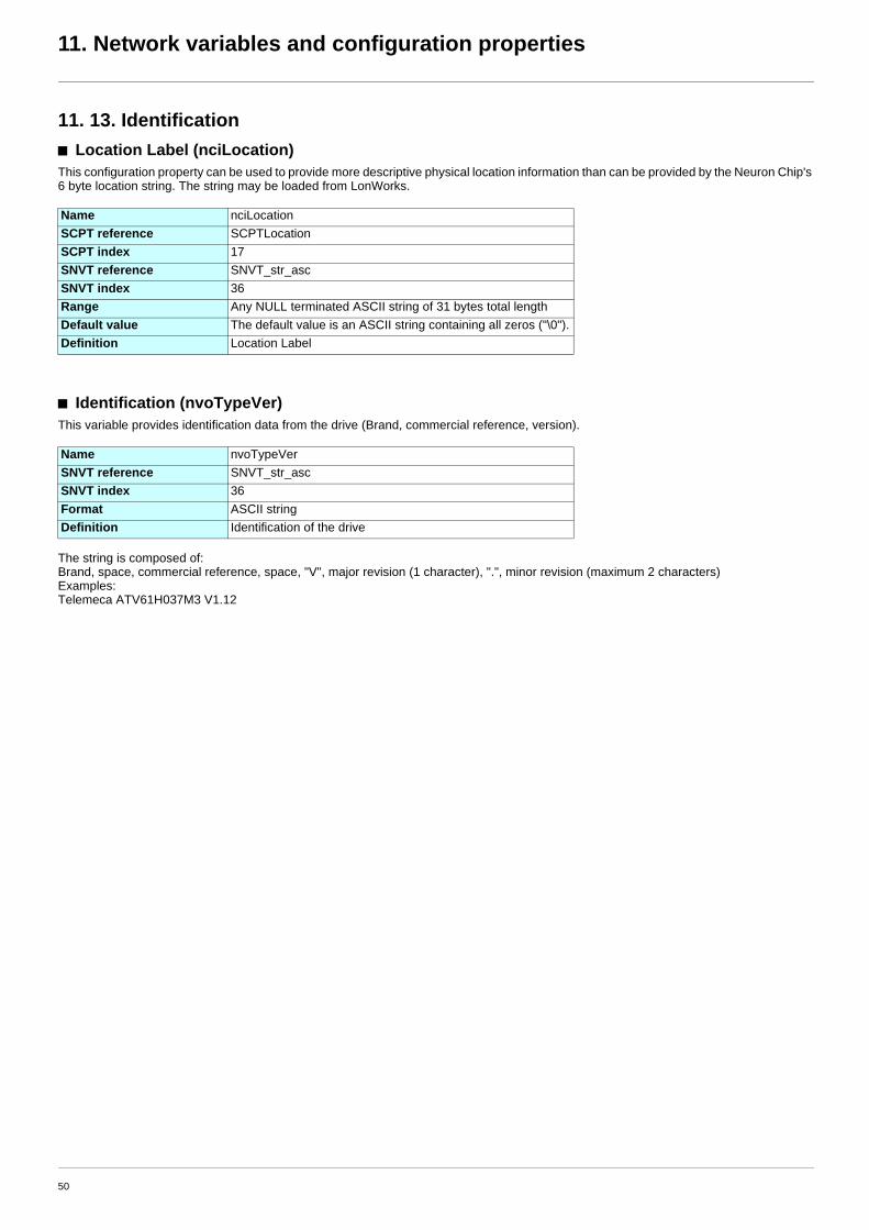
11. Network variables and configuration properties
11. 13. Identificationb Location Label (nciLocation)This configuration property can be used to provide more descriptive physical location information than can be provided by the Neuron Chip's6 byte location string. The string may be loaded from LonWorks.
b Identification (nvoTypeVer)This variable provides identification data from the drive (Brand, commercial reference, version).
The string is composed of:Brand, space, commercial reference, space, "V", major revision (1 character), ".", minor revision (maximum 2 characters)Examples:Telemeca ATV61H037M3 V1.12
Name nciLocationSCPT reference SCPTLocationSCPT index 17SNVT reference SNVT_str_ascSNVT index 36Range Any NULL terminated ASCII string of 31 bytes total lengthDefault value The default value is an ASCII string containing all zeros ("\0").Definition Location Label
Name nvoTypeVerSNVT reference SNVT_str_ascSNVT index 36Format ASCII stringDefinition Identification of the drive
50

11. Network variables and configuration properties
11. 14. Network managementb Send Heartbeat Time (nciSndHrtBt)This configuration property defines the maximum period of time that expires before automatic update of the network variables:• Drive Speed Feedback (nvoDrvSpeed),• Drive Output Current (nvoDrvCurnt),• Drive Output Voltage (nvoDrvVolt),• Drive Output Power (nvoDrvPwr),
b Receive Heartbeat Time (nciRcvHrtBt)This configuration property is used to control the maximum time that elapses after the last update of at least one of the network variables:• Drive Speed Setpoint (nviDrvSpeedStpt),• Drive Speed Setpoint Scaling (nviDrvSpeedScale),• Frequency setpoint (nviInvSetFreq).
When these variables are not updated within the heartbeat time the drive will trip in [Com.network] (CnF) fault and nviDrvSpeed,nviDrvSpeedScale and nviInvSetFreq will return to their initial value.
It is possible to configure another behaviour of the drive, pease refer to “Communication faults”, page 21
Name nciSndHrtBtSCPT reference SCPTmaxSendTimeSCPT index 49SNVT reference SNVT_time_secSNVT index 107Unit 0.1 secRange 0.0 ... 6 553.4 secDefault value 0 (no automatic update)Definition Send Heartbeat Time
Name nciRcvHrtBtSCPT reference SCPTmaxRcvTimeSCPT index 48SNVT reference SNVT_str_ascSNVT index 36Unit 0.1 secRange 0.1 ... 6 553.4 sec
0.0 (no failure detection)Default value 0.0 (no failure detection)Definition Receive Heartbeat Time
WARNINGIf this function is not properly set up, it may cause an accident.If you configure the configuration property Receive Heartbeat Time (nciRcvHrtBt) to the value 0.0, the drive will not trip in drivecommunication fault [Com. network] (CnF).As soon as the LONWORKS communication comes back, the drive will restart according to the LonWorks control.
This is the default value according to the LONMARK standard.
Failure to follow this instruction can result in death, serious injury or equipment damage.
51

11. Network variables and configuration properties
b Minimum Send Time (nciMinOutTm)This configuration property defines the minimum period of time between automatic network variable transmissions.
b Power supply start waiting time (nciPwUpOutTm)Waiting time until the drive starts transmission after reset or power on.When a setting value is 0, transmission will start after the initialization of the LonWorks card is finished.
Name nciMinOutTmSCPT reference SCPTminSendTimeSCPT index 52SNVT reference SNVT_time_secSNVT index 107Unit 0.1 secRange 0.0 to 6 553.4 sec0.0 disables transmissionDefault value 0.5 secDefinition Minimum Send Time
Name nciPwUpOutTmSCPT referenceSCPT indexSNVT reference SNVT_time_secSNVT index 107Unit 0.1 secRange
0.0 to 6 553.4 sec0.0: Transmission starts immediately after initialisation of the LonWorks card is finished.
Default value 0.5 secDefinition Power supply start waiting time
52

11. Network variables and configuration properties
11. 15. Scannerb Communication scanner (nviScannerOut1, nvoScannerIn1)These two network variables may be linked to any parameter of the drive by configuration. Refer to 8. 3. Communication scanner.
These network variables allow exchange of drive parameters that are not listed in the LonWorks interface.
When a Controller Inside card is installed in the drive, they enable the controller to communicate with the application of the Controller Insidecard.
These LonWorks network variables are linked to the drive parameters:nviScannerOut1: Communication scanner, value of write word 1 (nC1) (12761 = 16#31D9).nvoScannerIn1: Communication scanner, value of read word 1 (nM1) (12741 = 16#31C5).
Name nviScannerOut1 Name nvoScannerIn1SNVT reference SNVT_count_inc SNVT reference SNVT_count_incSNVT index 9 SNVT index 9Definition Communication scanner out 1 Definition Communication scanner in 1
WARNINGIf this function is not properly set up, it may cause an accident.
Any drive parameter can be linked to nviScannerOut1 but the user must follow two rules :
1 The user must not link nviScannerOut1 to any command or speed or frequency setpoint parameter of the drive (CMd, CMI, LFR, LFRD).2 The user must not link nviScannerOut1 to any setting parameter of the drive that is already linked to a network variable.
Failure to follow this instruction can result in death, serious injury or equipment damage.
53

2006-08
atv61_LONWORKS_EN_V2