Embed Size (px)
Citation preview
2354235 11/2008
BB
V2
85
87
www.schneider-electric.com
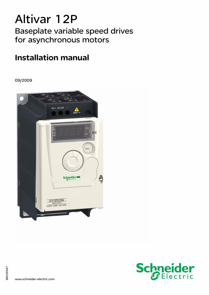
Altivar 12PBaseplate variable speed drivesfor asynchronous motors
Installation manual
09/2009

BBV28587 09/2009 3
Contents
Important Information __________________________________________________________________________________________ 4Before you begin______________________________________________________________________________________________ 5Documentation structure________________________________________________________________________________________ 6Product Overview _____________________________________________________________________________________________ 7Check list ___________________________________________________________________________________________________ 8Drive ratings _________________________________________________________________________________________________ 9Dimensions and weights_______________________________________________________________________________________ 11Conditions of Acceptability (CA) _________________________________________________________________________________ 12Mounting___________________________________________________________________________________________________ 13Thermal resistances and losses _________________________________________________________________________________ 15
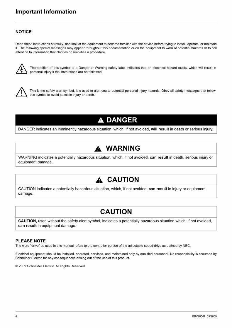
Important Information
NOTICE
Read these instructions carefully, and look at the equipment to become familiar with the device before trying to install, operate, or maintainit. The following special messages may appear throughout this documentation or on the equipment to warn of potential hazards or to callattention to information that clarifies or simplifies a procedure.
PLEASE NOTEThe word "drive" as used in this manual refers to the controller portion of the adjustable speed drive as defined by NEC.
Electrical equipment should be installed, operated, serviced, and maintained only by qualified personnel. No responsibility is assumed bySchneider Electric for any consequences arising out of the use of this product.
© 2009 Schneider Electric All Rights Reserved
DANGERDANGER indicates an imminently hazardous situation, which, if not avoided, will result in death or serious injury.
WARNINGWARNING indicates a potentially hazardous situation, which, if not avoided, can result in death, serious injury or equipment damage.
CAUTIONCAUTION indicates a potentially hazardous situation, which, if not avoided, can result in injury or equipment damage.
CAUTIONCAUTION, used without the safety alert symbol, indicates a potentially hazardous situation which, if not avoided, can result in equipment damage.
The addition of this symbol to a Danger or Warning safety label indicates that an electrical hazard exists, which will result inpersonal injury if the instructions are not followed.
This is the safety alert symbol. It is used to alert you to potential personal injury hazards. Obey all safety messages that followthis symbol to avoid possible injury or death.
4 BBV28587 09/2009
Before you begin
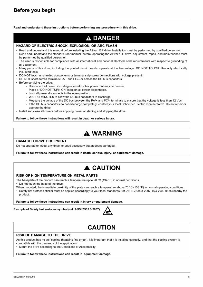
Read and understand these instructions before performing any procedure with this drive.
Example of Safety hot surfaces symbol (ref. ANSI Z535.3-2007):
DANGERHAZARD OF ELECTRIC SHOCK, EXPLOSION, OR ARC FLASH• Read and understand this manual before installing the Altivar 12P drive. Installation must be performed by qualified personnel.• Read and understand the standard user manual before operating the Altivar 12P drive. adjustment, repair, and maintenance must
be performed by qualified personnel.• The user is responsible for compliance with all international and national electrical code requirements with respect to grounding of
all equipment.• Many parts of this drive, including the printed circuit boards, operate at the line voltage. DO NOT TOUCH. Use only electrically
insulated tools.• DO NOT touch unshielded components or terminal strip screw connections with voltage present.• DO NOT short across terminals PA/+ and PC/– or across the DC bus capacitors.• Before servicing the drive:
- Disconnect all power, including external control power that may be present.- Place a “DO NOT TURN ON” label on all power disconnects.- Lock all power disconnects in the open position.- WAIT 15 MINUTES to allow the DC bus capacitors to discharge.- Measure the voltage of the DC bus between the PA/+ and PC/– terminals to ensure that the voltage is less than 42 Vdc.- If the DC bus capacitors do not discharge completely, contact your local Schneider Electric representative. Do not repair or
operate the drive• Install and close all covers before applying power or starting and stopping the drive.
Failure to follow these instructions will result in death or serious injury.
WARNINGDAMAGED DRIVE EQUIPMENTDo not operate or install any drive or drive accessory that appears damaged.
Failure to follow these instructions can result in death, serious injury, or equipment damage.
CAUTIONRISK OF HIGH TEMPERATURE ON METAL PARTSThe baseplate of the product can reach a temperature up to 90 °C (194 °F) in normal conditions.• Do not touch the base of the drive.When mounted, the immediate proximity of the plate can reach a temperature above 70 °C (158 °F) in normal operating conditions.• Safety hot surfaces sticker must be applied accordingly to your local standards (ref. ANSI Z535.3-2007, ISO 7000-0535) nearby the
product.
Failure to follow these instructions can result in injury or equipment damage.
CAUTIONRISK OF DAMAGE TO THE DRIVEAs this product has no self cooling (heatsink fins or fan), it is important that it is installed correctly, and that the cooling system is compatible with the demands of the application. • Mount the drive according to the Conditions of Acceptability.
Failure to follow these instructions can result in equipment damage.
BBV28587 09/2009 5

Documentation structure
The following Altivar 12 technical documents are available on the Schneider Electric website (www.schneider-electric.com) as well as onDVD-ROM (reference VW3A8200).
User manualThis manual describes how to install, program and operate the drive.
Simplified manualThis manual is a simplified version of the User manual. This manual is delivered with the drive.
Quick Start sheetThe Quick Start describes how to wire and configure the drive to start motor quickly and simply for simple applications. This document isdelivered with the drive.
Modbus Communication manualThis manual describes the assembly, connection to the bus or network, signaling, diagnostics, and configuration of the communication-specific parameters via the 7 segment LED display.It also describes the communication services of the Modbus protocol.This manual includes all Modbus addresses. It explains the operating mode specific to communication (state chart).
ATV12P Installation manualThis manual describes how to install the drives following the conditions of acceptability.
6 BBV28587 09/2009
Product Overview
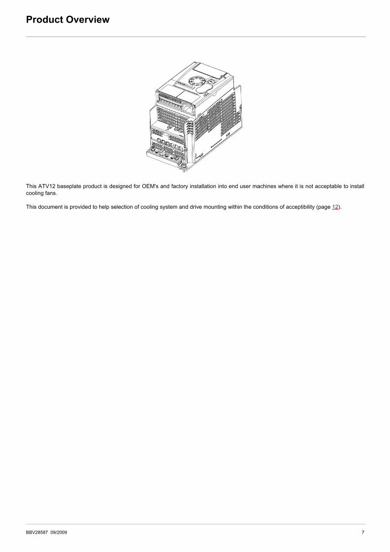
This ATV12 baseplate product is designed for OEM's and factory installation into end user machines where it is not acceptable to installcooling fans.
This document is provided to help selection of cooling system and drive mounting within the conditions of acceptibility (page 12).
BBV28587 09/2009 7
Check list
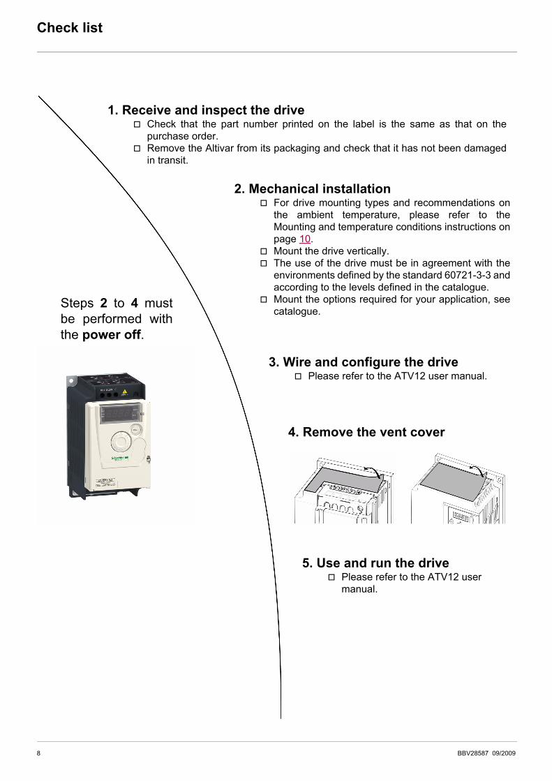
1. Receive and inspect the drivev Check that the part number printed on the label is the same as that on the
purchase order.v Remove the Altivar from its packaging and check that it has not been damaged
in transit.
2. Mechanical installationv For drive mounting types and recommendations on
the ambient temperature, please refer to theMounting and temperature conditions instructions onpage 10.
v Mount the drive vertically.v The use of the drive must be in agreement with the
environments defined by the standard 60721-3-3 andaccording to the levels defined in the catalogue.
v Mount the options required for your application, seecatalogue.
3. Wire and configure the drivev Please refer to the ATV12 user manual.
Steps 2 to 4 mustbe performed withthe power off.
4. Remove the vent cover
5. Use and run the drivev Please refer to the ATV12 user
manual.
8 BBV28587 09/2009
Drive ratings
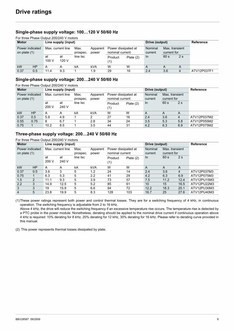
Single-phase supply voltage: 100…120 V 50/60 HzFor three Phase Output 200/240 V motors
Single-phase supply voltage: 200…240 V 50/60 HzFor three Phase Output 200/240 V motors
Three-phase supply voltage: 200…240 V 50/60 HzFor three Phase Output 200/240 V motors
(1)These power ratings represent both power and control thermal losses. They are for a switching frequency of 4 kHz, in continuousoperation. The switching frequency is adjustable from 2 to 16 kHz.Above 4 kHz, the drive will reduce the switching frequency if an excessive temperature rise occurs. The temperature rise is detected bya PTC probe in the power module. Nonetheless, derating should be applied to the nominal drive current if continuous operation above4 kHz is required: 10% derating for 8 kHz, 20% derating for 12 kHz, 30% derating for 16 kHz. Please refer to derating curve provided inthis manual.
(2) This power represents thermal losses dissipated by plate.
Motor Line supply (input) Drive (output) Reference
Power indicated on plate (1)
Max. current line Max.prospec.line Isc
Apparentpower
Power dissipated at nominal current
NominalcurrentIn
Max. transient current for
at100 V
at120 V
Product (1)
Plate (2) 60 s 2 s
kW HP A A kA kVA W W A A A0.37 0.5 11.4 9.3 1 1.9 29 16 2.4 3.6 4 ATV12P037F1
Motor Line supply (input) Drive (output) ReferencePower indicated on plate (1)
Max. current line Max.prospec.line Isc
Apparentpower
Power dissipated at nominal current
NominalcurrentIn
Max. transient current for
at200 V
at240 V
Product (1)
Plate (2) 60 s 2 s
kW HP A A kA kVA W W A A A0.37 0.5 5.9 4.9 1 2 27 16 2.4 3.6 4 ATV12P037M20.55 0.75 8 6.7 1 2.8 34 24 3.5 5.3 5.8 ATV12P055M20.75 1 10.2 8.5 1 3.5 44 31 4.2 6.3 6.9 ATV12P075M2
Motor Line supply (input) Drive (output) ReferencePower indicated on plate (1)
Max. current line Max.prospec.line Isc
Apparentpower
Power dissipated at nominal current
NominalcurrentIn
Max. transient current for
at200 V
at240 V
Product (1)
Plate (2) 60 s 2 s
kW HP A A kA kVA W W A A A0.37 0.5 3.6 3 5 1.2 24 14 2.4 3.6 4 ATV12P037M30.75 1 6.3 5.3 5 2.2 41 29 4.2 6.3 6.9 ATV12P075M31.5 2 11.1 9.3 5 3.9 73 57 7.5 11.2 12.4 ATV12PU15M32.2 3 14.9 12.5 5 5.2 85 61 10 15 16.5 ATV12PU22M33 3 19 15.9 5 6.6 94 72 12.2 18.3 20.1 ATV12PU30M34 5 23.8 19.9 5 8.3 128 103 16.7 25 27.6 ATV12PU40M3
BBV28587 09/2009 9
Drive ratings
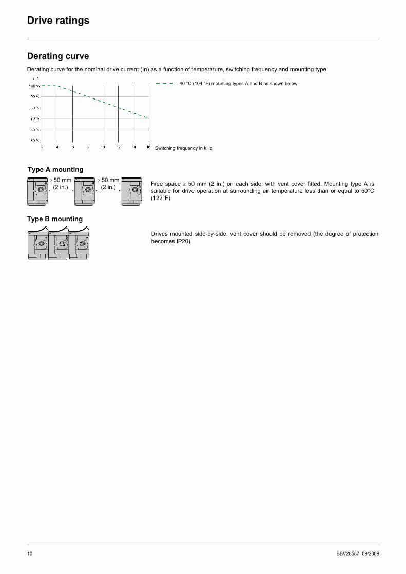
Derating curveDerating curve for the nominal drive current (In) as a function of temperature, switching frequency and mounting type.
40 °C (104 °F) mounting types A and B as shown below
Switching frequency in kHz
Type A mounting
Free space ≥ 50 mm (2 in.) on each side, with vent cover fitted. Mounting type A issuitable for drive operation at surrounding air temperature less than or equal to 50°C(122°F).
≥ 50 mm(2 in.)
≥ 50 mm(2 in.)
Type B mounting
Drives mounted side-by-side, vent cover should be removed (the degree of protectionbecomes IP20).
10 BBV28587 09/2009
Dimensions and weights
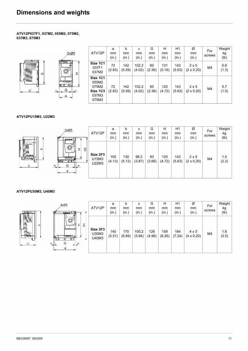
ATV12P037F1, 037M2, 055M2, 075M2,037M3, 075M3
ATV12PU15M3, U22M3
ATV12PU30M3, U40M3
ATV12Pa
mm(in.)
bmm(in.)
cmm(in.)
Gmm(in.)
Hmm(in.)
H1mm(in.)
Ømm(in.)
For screws
Weightkg(lb)
Size 1C1037F1037M2
72(2.83)
142(5.59)
102.2(4.02)
60(2.36)
131(5.16)
143(5.63)
2 x 5(2 x 0.20) M4 0.6
(1.3)
Size 1C1055M2075M2
Size 1C3037M3075M3
72(2.83)
142(5.59)
102.2(4.02)
60(2.36)
120(4.72)
143(5.63)
2 x 5(2 x 0.20) M4 0.7
(1.5)
ATV12Pa
mm(in.)
bmm(in.)
cmm(in.)
Gmm(in.)
Hmm(in.)
H1mm(in.)
Ømm(in.)
For screws
Weightkg(lb)
Size 2F3U15M3U22M3
105(4.13)
130(5.12)
98.2(3.87)
93(3.66)
120(4.72)
143(5.63)
2 x 5(2 x 0.20) M4 1.0
(2.2)
ATV12Pa
mm(in.)
bmm(in.)
cmm(in.)
Gmm(in.)
Hmm(in.)
H1mm(in.)
Ømm(in.)
For screws
Weightkg(lb)
Size 3F3U30M3U40M3
140(5.51)
170(6.69)
100.2(3.94)
126(4.96)
159(6.26)
184(7.24)
4 x 5(4 x 0.20) M4 1.6
(3.5)
BBV28587 09/2009 11
Conditions of Acceptability (CA)
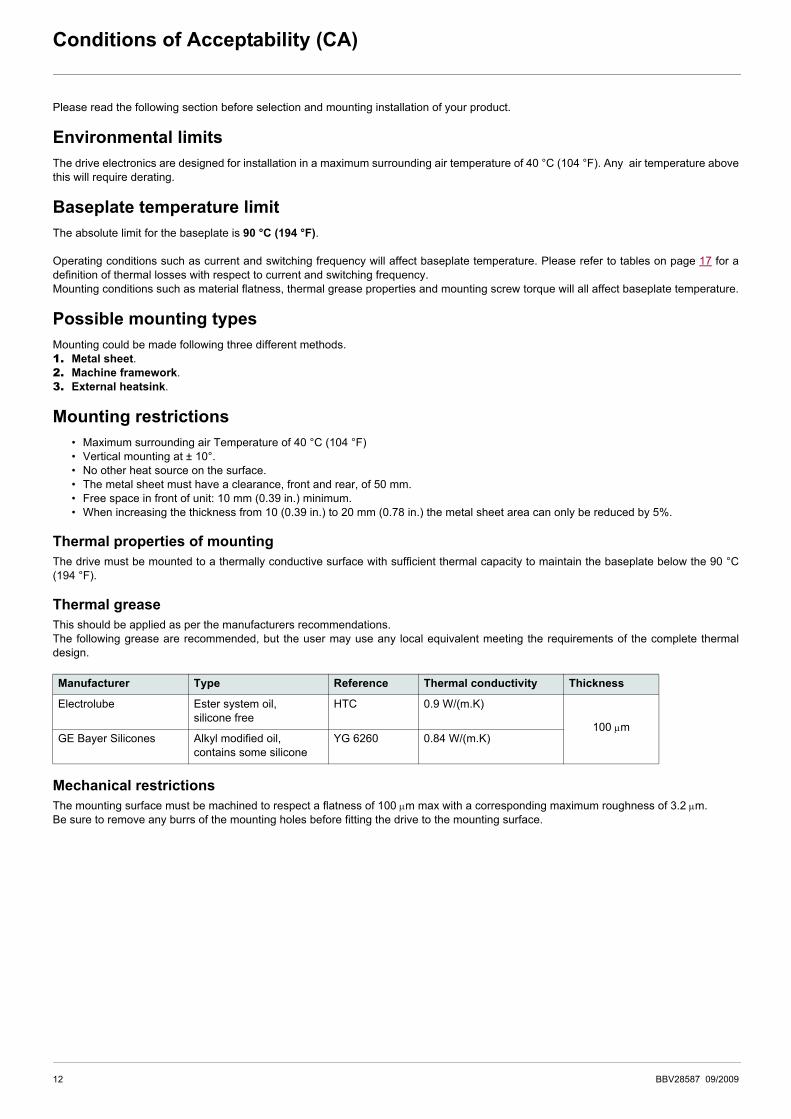
Please read the following section before selection and mounting installation of your product.
Environmental limitsThe drive electronics are designed for installation in a maximum surrounding air temperature of 40 °C (104 °F). Any air temperature abovethis will require derating.
Baseplate temperature limitThe absolute limit for the baseplate is 90 °C (194 °F).
Operating conditions such as current and switching frequency will affect baseplate temperature. Please refer to tables on page 17 for adefinition of thermal losses with respect to current and switching frequency.Mounting conditions such as material flatness, thermal grease properties and mounting screw torque will all affect baseplate temperature.
Possible mounting typesMounting could be made following three different methods.1. Metal sheet.2. Machine framework.3. External heatsink.
Mounting restrictions• Maximum surrounding air Temperature of 40 °C (104 °F)• Vertical mounting at ± 10°.• No other heat source on the surface.• The metal sheet must have a clearance, front and rear, of 50 mm.• Free space in front of unit: 10 mm (0.39 in.) minimum.• When increasing the thickness from 10 (0.39 in.) to 20 mm (0.78 in.) the metal sheet area can only be reduced by 5%.
Thermal properties of mountingThe drive must be mounted to a thermally conductive surface with sufficient thermal capacity to maintain the baseplate below the 90 °C(194 °F).
Thermal greaseThis should be applied as per the manufacturers recommendations.The following grease are recommended, but the user may use any local equivalent meeting the requirements of the complete thermaldesign.
Mechanical restrictionsThe mounting surface must be machined to respect a flatness of 100 μm max with a corresponding maximum roughness of 3.2 μm.Be sure to remove any burrs of the mounting holes before fitting the drive to the mounting surface.
Manufacturer Type Reference Thermal conductivity Thickness
Electrolube Ester system oil,silicone free
HTC 0.9 W/(m.K)
100 μmGE Bayer Silicones Alkyl modified oil,
contains some siliconeYG 6260 0.84 W/(m.K)
12 BBV28587 09/2009
Mounting
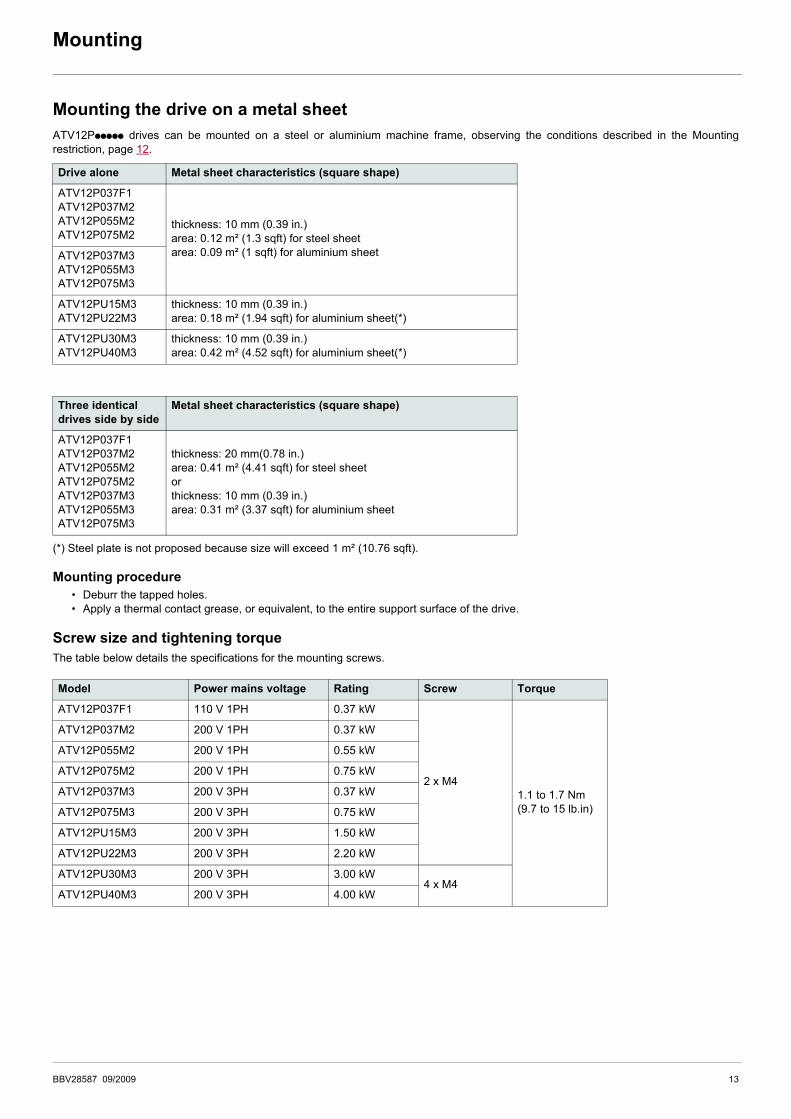
Mounting the drive on a metal sheetATV12Pppppp drives can be mounted on a steel or aluminium machine frame, observing the conditions described in the Mountingrestriction, page 12.
(*) Steel plate is not proposed because size will exceed 1 m² (10.76 sqft).
Mounting procedure• Deburr the tapped holes.• Apply a thermal contact grease, or equivalent, to the entire support surface of the drive.
Screw size and tightening torqueThe table below details the specifications for the mounting screws.
Drive alone Metal sheet characteristics (square shape)
ATV12P037F1ATV12P037M2ATV12P055M2ATV12P075M2
thickness: 10 mm (0.39 in.)area: 0.12 m² (1.3 sqft) for steel sheet area: 0.09 m² (1 sqft) for aluminium sheetATV12P037M3
ATV12P055M3ATV12P075M3
ATV12PU15M3ATV12PU22M3
thickness: 10 mm (0.39 in.)area: 0.18 m² (1.94 sqft) for aluminium sheet(*)
ATV12PU30M3ATV12PU40M3
thickness: 10 mm (0.39 in.)area: 0.42 m² (4.52 sqft) for aluminium sheet(*)
Three identical drives side by side
Metal sheet characteristics (square shape)
ATV12P037F1ATV12P037M2ATV12P055M2ATV12P075M2ATV12P037M3ATV12P055M3ATV12P075M3
thickness: 20 mm(0.78 in.)area: 0.41 m² (4.41 sqft) for steel sheetorthickness: 10 mm (0.39 in.)area: 0.31 m² (3.37 sqft) for aluminium sheet
Model Power mains voltage Rating Screw Torque
ATV12P037F1 110 V 1PH 0.37 kW
2 x M41.1 to 1.7 Nm(9.7 to 15 lb.in)
ATV12P037M2 200 V 1PH 0.37 kW
ATV12P055M2 200 V 1PH 0.55 kW
ATV12P075M2 200 V 1PH 0.75 kW
ATV12P037M3 200 V 3PH 0.37 kW
ATV12P075M3 200 V 3PH 0.75 kW
ATV12PU15M3 200 V 3PH 1.50 kW
ATV12PU22M3 200 V 3PH 2.20 kW
ATV12PU30M3 200 V 3PH 3.00 kW4 x M4
ATV12PU40M3 200 V 3PH 4.00 kW
BBV28587 09/2009 13

Mounting
Mounting the drive on an external heatsink and machine frameworkThe following conditions must followed for correct installation:
• Determination of the suitable thermal resistance (Rth), see page 15,• Selection of heatsink or framework which has a thermal resistance lower or equal to the determined value (Rth).
Mounting procedure• Deburr the tapped holes.• Apply a thermal contact grease, or equivalent, to the entire support surface of the drive.• Follow mounting restrictions page 12.
CAUTIONRISK OF DAMAGE TO DRIVEWhen using external heatsink, the cooling solution must be calculated assuming the heat source is of the concentrated type.The following information is to be given to the cooling solution manufacturer:• required concentrated Rth,• source dimension,• thermal losses.
Failure to follow these instructions can result in equipment damage
14 BBV28587 09/2009

Thermal resistances and losses
The global thermal resistance of your system Rth, expressed in K/W (for kelvin per watt), is defined by the following formula:
See Thermal losses Load values in the table page 17.
The global thermal resistance Rth is equal to the sum of 3 components:• "RBP: baseplate thermal resistance, see page 17.• "RG: grease thermal resistance, see page 17.• "RExt: External heatsink thermal resistance, see page 17
Re-arranging equation (1) and (2), we can calculate the thermal resistance of external heatsink required to satisfy the 90 °C (194 °F)requirement for the baseplate, namely:
The calculated RExt is the maximum thermal resistance value for a heat sink that would fit for the application. We recommend to incorporate a 10% margin ; this margin is already included in the values on table page 17.
Equ. 1
Equ. 2
baseplate thermal resistance: RBP
Grease thermal resistance: RGExternal heatsink Resistance: RExt Example: machine frame
Equ. 3
Rth90 Tambient–
Load-----------------------------------=
Rth RBP RG RExt+ +=
RExt90 Tambient–
Load----------------------------------- RBP– RG–=
BBV28587 09/2009 15

Thermal resistances and losses
Choosing a heat sink for the productThe choice of a heat sink depends on your installation. Here are a few tips to help you find the correct heat sink for your application :
• Heat sink base shall be at least as large as the product baseplate (please refer to table page 9 for dimensional information),• Heat sink thermal resistance shall fit with the values given on page 9.
Note: Thermal resistance is not a characteristic of a heat sink, but it is actually of a {heat sink + source} system, as the source shape stronglyaffects the value. Most heat sink manufacturers give their products with a thermal resistance value calculated accordingly to a source whichhas the same surface than the heat sink base. If your heat sink is larger than your ATV 12 P product, please refer to the manufacturer toget the corrected thermal resistance. This corrected value is to be compared to the specifications page 9.
16 BBV28587 09/2009

Thermal resistances and losses
Single-phase supply voltage: 100…120 V 50/60 Hz
Single-phase supply voltage: 200…240 V 50/60 Hz
Three-phase supply voltage: 200…240 V 50/60 Hz
(1)See definition on page 15. The table takes into account a 10% margin.(2)K/W: kelvin per watt(3)Concentrated heatsource(4)These losses take into account the derating used for switching frequency.
Drive Frequency Thermallosses(4) LOAD
Thermaldensity
Concentrated heatsource surface area
Thermal resistance Rth (1)baseplateRBP
greaseRG
Externalheatsink RExt (3)
ATV12P kHz W W/m² (W/sqft) mm (in.) K/W (2) K/W (2) K/W (2)037F1 4 to 16 17 1816 (169) 72 x 130 (2.83 x 5.12) 0,04 0,012 2,6
Drive Frequency Thermallosses(4) LOAD
Thermaldensity
Concentrated heatsource surface area
Thermal resistance Rth (1)baseplateRBP
greaseRG
Externalheatsink RExt (3)
ATV12P kHz W W/m² (W/sqft) mm (in.) K/W (2) K/W (2) K/W (2)
037M2
4 16 1709 (159) 72 x 130 (2.83 x 5.12) 0,04 0,012 2,758 17 1816 (169) 72 x 130 (2.83 x 5.12) 0,04 0,012 2,612 18 1923 (179) 72 x 130 (2.83 x 5.12) 0,04 0,012 2,4516 18 1923 (179) 72 x 130 (2.83 x 5.12) 0,04 0,012 2,45
055M2 4 to 16 24 2564 (238) 72 x 130 (2.83 x 5.12) 0,04 0,012 1.82075M2 4 to 16 31 3312 (308) 72 x 130 (2.83 x 5.12) 0,04 0,012 1.4
Drive Frequency Thermallosses(4) LOAD
Thermaldensity
Concentrated heatsource surface area
Thermal resistance Rth (1)baseplateRBP
greaseRG
Externalheatsink RExt (3)
ATV12P kHz W W/m² (W/sqft) mm (in.) K/W (2) K/W (2) K/W (2)
037M3
4 14 1496 (139) 72 x 130 (2.83 x 5.12) 0,04 0,012 3,168 15 1603 (149) 72 x 130 (2.83 x 5.12) 0,04 0,012 2,9512 16 1709 (159) 72 x 130 (2.83 x 5.12) 0,04 0,012 2,7616 16 1709 (159) 72 x 130 (2.83 x 5.12) 0,04 0,012 2,76
055M3 4 23 2457 (228) 72 x 130 (2.83 x 5.12) 0,04 0,012 1.9075M3 4 to 16 29 3098 (288) 72 x 130 (2.83 x 5.12) 0,04 0,012 1.5
U15M3
4 57 4176 (388) 72 x 130 (2.83 x 5.12) 0,012 0,008 0,778 64 4689 (436) 72 x 130 (2.83 x 5.12) 0,012 0,008 0,6812 69 5055 (470) 72 x 130 (2.83 x 5.12) 0,012 0,008 0,6316 71 5201 (483) 72 x 130 (2.83 x 5.12) 0,012 0,008 0,61
U22M3
4 61 4469 (415) 72 x 130 (2.83 x 5.12) 0,012 0,008 0,718 62 4542 (422) 72 x 130 (2.83 x 5.12) 0,012 0,008 0,712 63 4615 (429) 72 x 130 (2.83 x 5.12) 0,012 0,008 0,6916 63 4615 (429) 72 x 130 (2.83 x 5.12) 0,012 0,008 0,69
U30M3
4 72 3025 (281) 140 x 170 (5.51 x 6.69) 0,004 0,0036 0,618 74 3109 (289) 140 x 170 (5.51 x 6.69) 0,004 0,0036 0,612 75 3151 (293) 140 x 170 (5.51 x 6.69) 0,004 0,0036 0,5916 75 3151 (293) 140 x 170 (5.51 x 6.69) 0,004 0,0036 0,59
U40M34 103 4328 (402) 140 x 170 (5.51 x 6.69) 0,004 0,0036 0,438 to 16 110 4622 (429) 140 x 170 (5.51 x 6.69) 0,004 0,0036 0,4
BBV28587 09/2009 17

ATV12P_User_manual_BBV28587_01
BBV28587 09/2009