Embed Size (px)
DESCRIPTION
Attitude dynamics and control
Citation preview

Attitude Determination and Control of Satellites

Introduction
• Attitude Determination and Control Subsystem(ADCS)
- Senses the orientation of spacecraft relative to reference plane usually inertial
- Stabillizes the spacecraft
- Orients the spacecraft in desired direction
Attitude control
Needed because
• Payload requirements
Eg. Focusing the satellite camera to a particular direction
• Communication requirements
Pointing the antenna towards ground
• Power system requirements
Tracking the sun to achieve maximum power generation

Components of ADCS
• Sensors- To determine the orientation of the satellite
• Algorithms-To calculate the deviation from the desired orientation and to generate actuation command to counter the deviation
• Actuators-To act upon the signals given by the control algorithms and to produce the necessary torques

CHANGE IN ATTITUDE
Satellite tends to change its orientation because of environmental torques
– Aerodynamic torque
– Solar radiation pressure
– Gravity gradient torque
– Interaction of Satellite electronics with earth’s magnetic field

Attitude Determination • Earth Sensor (horizon sensor)
– Use IR to detect boundary between deep space & upper atmosphere
– Typically scanning (can also be an actuator) • Sun Sensor • Star Sensor
– Scanner: for spinning S/C or on a rotating mount – Tracker/Mapper: for 3-axis stabilized S/C
• Tracker (one star) / Mapper (multiple stars)
• Inertial Measurement Unit (IMU) – Rate Gyros (may also include accelerometers)
• Magnetometer – Requires magnetic field model stored in computer

Attitude Control
• Actuators come in two types
– Passive
• Gravity Gradient Boom
• Spinning
– Active
• Thrusters
• Wheels
• Gyros
• Torque Rods

Reference frames
• Earth Centered Inertial Frame: Non rotating reference frame denoted by .
Origin : Center of Earth
x –axis : Points towards vernal equinox
y – axis: 90⁰ east in the equatorial plane
z - axis: Extends through North pole


• Earth-Centered Earth Fixed (ECEF) Frame:
x and y axes rotate with the hemisphere relative to ECI frame
origin: center of earth
x-axis: Points toward the intersection of Greenwich meridian and equator
z-axis: Extends through the North pole and rotation is about z axis
y-axis: Completes right handed system.


• Orbit Frame:
Origin: Center of mass of the satellite
x-axis: Points in the direction of motion tangentially to the orbit
z-axis: Points Nadhir (center of Earth)
y-axis: Completes right handed system


• Body frame:
Origin: Coincides with the center of mass of the satellite.
x and y axes: Coincides with the orbit frame axes when the satellite has an attitude of 0⁰ in roll, pitch and yaw.
z-axis: Nadhir side of satellite


Rotation Matrix
Rotation matrix is a description of the rotational relationship between two reference frame.
The rotation matrix R from frame a to b is denoted as Rᵇₐ.
Rotation of a vector from one frame to another frame be given using Rᵇₐ as

• Rotational matrices are denoted by SO(3)
The orientation of satellite is described using rotation matrix
Relation between angular velocity and rotation matrix, and its derivative is
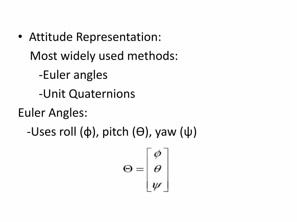
• Attitude Representation:
Most widely used methods:
-Euler angles
-Unit Quaternions
Euler Angles:
-Uses roll (ф), pitch (ϴ), yaw (ψ)


• Transforming the body from the inertial axes to rotated body fixed axes using a rotation matrix:
Where I, j, k are chosen rotation axes and
are transposes of the elementary rotation matrices about their respective axes.

• Unit Quaternions:
-Choose euler axis
- Rotate the object by an angle ф from inertial frame about the euler axis.

Inertia Matrix
Inertia matix Iₒ about origin is defined as

Dynamics of Satellite
Consider satellite as rigid body h = r x p h= IѠ Where h – angular momentum r – position vector p – linear momentum I – moment of inertia Ѡ – angular velocity

Mathematical dynamic model of satellite:
: angular velocity of the body frame with respect to the inertial frame in the body frame
: Torques acting on the satellite in body frame both internal and external.

Modeling of Reaction wheel
• Torque produced by reaction wheel:
: Torque produced by reaction wheel in body frame
is angular momentum of reaction wheels
is friction of reaction wheel

Mathematical Model of spacecraft Attitude System
- (1)
- (2)
- (3)
where is attitude angular velocity expresses in spacecraft’s body fixed reference frame to inertial frame
: rotation inertial matrix
: angular momentum of spacecraft

is attitude angles described by Euler angles and

References
• LI Long, Hou Jianwen. Adaptive Sliding Mode Based Controller Design for Spacecraft Attitude Stabilization, IEEE transactions, 2015
• Attitude determination and control by James R Wertz
• Spacecraft Dynamics and Control by Marcel J. SIDI,1997