Embed Size (px)
Citation preview

Installation important information ...........Page 1
Stages of installation ...............................Page 2
Preparing the wall opening/cavity ...........Page 3
Installing the VZCC .................................Page 5
Installing the Ultra Insert firebox .............Page 6
Installing the ECO Built-In flue kit ...........Page 7
Floor protector requirements ..................Page 9
Fitting the fascia ...................................Page 11
Fits Metro Ultra Insert
Ultra Insert Vented Zero Clearance Cabinet Installation Manual
19 Oropuriri Road // New Plymouth 4312
[email protected] // www.metrofires.co.nz
09/1
9 ©
PIO
NEE
R M
AN
UFA
CTU
RIN
G L
TD
Installation of the Ultra Insert models into a Vented Zero Clearance Cabinet (VZCC) elevates the appliance and fascia by 45mm.
To complete installation to conceal the VZCC base runners, a Metro Pine Insert insulated floor protector or Ultra Insert Fascia Base Rail are options available. (See page 9/10)
ATTENTION!
Ultra Insert Vented Zero Clearance Cabinet (VZCC)

1
The Ultra Insert ‘Vented Zero Clearance Cabinet’ (VZCC)
The function of the Metro Ultra Insert Vented Zero Clearance Cabinet
(VZCC) is to enable the Metro Ultra Insert to be installed into a timber
framed wall replacing a masonry chimney at a fraction of the cost.
1. Installation must be strictly in accordance with this manual to comply
with the test approvals to AS/NZS 2918:2001 held by Pioneer
Manufacturing Ltd. The installation of any model wood fire other than
the Ultra Insert into this VZCC will not comply with the test approvals
held by Pioneer Manufacturing Ltd and may be a fire risk.
2. Certain points within this manual are critical to the safe operation
of the VZCC. These points are highlighted with a ‘WARNING’ or
‘CAUTION’ heading and detailed within a black or grey panel.
3. Insulating spacer blocks are attached to the rear, sides and top
of the VZCC. These blocks must not be removed, they may touch
timber framing as their function is to ensure a minimum airspace
is maintained between the VZCC and any combustible framing or
materials.
4. There must be a minimum clearance of 30mm between the cabinet
top and the underside of the timber lintel.
5. There is a white insulating blanket pre-fitted to the Metro Ultra Insert
models outer cabinet. It is important that this insulating blanket
remains installed and in good condition. Do not remove this blanket
under any circumstances.
6. Please also refer to Stage 6 in relation to the Floor Protector
requirements prior to commencing installation.
Having read the six critical points above, unpack and familiarise yourself
with the various components of the VZCC as detailed and illustrated in
Diagram 1 opposite.
Supplied in the VZCC Pack:
1 x Assembled cabinet body
1 x 200mm/250mm diameter liner spigot
1 x Bag of assembly screws, bolts and nuts
1 x Installation manual
Not Supplied BUT REQUIRED:4 x Restraint fixtures, masonry anchors or wood screws
1 x Metro ECO Built-In flue system
1 x Metro Ultra Insert firebox with fascia
DIAGRAM 1
Unpacking and familiarisation
WARNING! Important Information• It is critical to the safe installation of a vented zero clearance
cabinet (VZCC) that you are conversant with the installation of
wood fires and competent to undertake this installation
• This vented zero clearance cabinet is for the Ultra Insert only
• You must read the following points prior to starting installation
200mm/250mm Diameter Liner Spigot
Mount Runners
Restraint Holes
Front Edge (Refer Stage 2)

2
Stages of installation
STAGE 1 Timber cavity construction
and preparation
STAGE 2 Vented Zero Clearance Cabinet
and liner spigot installation
STAGE 3 Insert firebox preparation
and installation into the VZCC
STAGE 4 ECO Built-In flue kit
assembly and installation
STAGE 5 Fit wall lining and floor protector
construction
STAGE 6 Fascia fitment and completion
of wall linings

3
Construction of the timber framed enclosure
1. Frame up the enclosure to specification. Combustible framing
materials are acceptable but a fire resistant wall board is required for
the fascia to sit against such as 9mm Promina board or equivalent.
Framed cavity internal dimensions
Internal width 740mm +/- 5mm Depth including wall lining 575mm +/- 5mm Height to underside of lintel 710mm +/- 5mm
Wall lining opening dimensions
Height 685mm +/- 5mm Width 740mm +/- 5mm Flue centreline 405mm
*Please note: If a brick front is to be built you will need to allow for
the thickness of the bricks.
2. For an ‘elevated’ installation we recommend you fix additional framing
beneath both sides and mount runners of the VZCC to support the
installation. You will also require additional framing to fix the wall
lining below the VZCC. The VZCC box can sit directly on the framing
but we recommend fitting a floor to provide seismic fixing points for
the VZCC. Insulation is not required under the VZCC.
For elevated installations, the floor protector may be installed after
the wood fire is in position as it does not extend into the enclosure.
However, the floor protectors rear edge must butt up against the non-
combustible wall lining below the heater, and the joint at that point
must be sealed to prevent the possibility of ember penetration.
3. A 1200mm x 1200mm sheet of 9mm Promina board or equivalent
non-combustible material is required around the fascia as illustrated
in Diagram 2.
It is usually convenient to carry the same lining material right up to
the ceiling level. The side lining of the enclosure may be standard gib
board or any other wall lining material.
Please note: Wall surfaces directly above the fascia may reach high
temperatures, so materials such as wallpaper and water based paint
may be adversely affected. For durability of finishes and surfaces you
should contact the relevant manufacturers for their specifications. Pioneer
Manufacturing Limited accepts no responsibility for the deterioration of
surfaces of finishes.
WARNING! Important Information• Access is required to fit the flue spigot adaptor to the VZCC
and for installation of the ECO Built-In flue kit. Pioneer
Manufacturing recommend lining the walls of the enclosure
after the VZCC and flue kit have been installed.
• As the VZCC is built into an enclosure, the enclosure must be
vented using one of the options detailed on page 4.
1200
mm
min
.
575mm
740mm
WARNING! Important InformationRECOMMENDED WALL LINING IS 9mm PROMINA BOARD OR EQUIVALENT NON-COMBUSTIBLE MATERIAL. PLEASE CONTACT THE RELEVANT MANUFACTURER FOR PRODUCT SPECIFICATIONS IF YOU CHOOSE TO USE A PRODUCT OTHER THAN PROMINA BOARD. FIRE RATED GIB BOARD IS NOT AN ACCEPTABLE MATERIAL TO USE AS AN EQUIVALENT.
DIAGRAM 2
Stage 1 - Construction and preparation of the wall opening/cavity
710m
m
1200mm min.
685m
m
405mm

4
Stage 1 - Construction and preparation of the wall opening/cavity
Cavity venting requirements
As the VZCC is built into an enclosure, the enclosure must be vented using
one of the three options detailed below.
Venting through an external wall will require suitable precautions to prevent
rodents and debris from entering or restricting the air vents. If grilles are
used, the minimum vent area must be maintained through the grille itself.
It is the responsibility of the installer to ensure the requirements of New
Zealand Building Code Clause E2 (External Moisture) are complied with.
A Venting through the ceiling space of the home
The enclosure is constructed to the full height of the room and is fully
open/vented into the ceiling cavity of the home.
B Venting through the side walls or rear wall of the cavity
A minimum open unrestricted vent area of 21,600mm2 is required to cool
the VZCC and flue liners within the combustible structure. This vent can
be positioned in the walls or floor of the cavity, but venting through external
cladding will need to be vermin proof and increased in size to ensure the
minimum unrestricted open area as specified.
C Venting through the ECO Option Kit
Venting through the top of the enclosure using the ‘ECO Option Kit’ with
the Metro ECO Built-In flue kit. If you choose to vent the enclosure with
this method there must be no internal ceiling or 2nd storey floor blocking
airflow within the cavity. The cavity must be fully open vertically from the
VZCC to the enclosure capping/flashing plate as indicated in Diagram 3
below (Venting through the ECO Option Kit). Please see Diagram 7 for the
ECO Option Kit installation.
Cavity venting
A Venting through the ceiling
B Venting through the cavity
C Venting through the
ECO Option Kit
1 Built-In appliance
2 Built-In flue kit
3 Flue system air outlet
Venting through ECO Option Kit
Venting through side or rear of cavity
Venting through side or rear of cavity
Venting via ceiling space
A
B B
C
CAUTION! Important InformationAS THE VZCC IS BUILT INTO AN ENCLOSURE, THE ENCLOSURE MUST BE VENTED USING ONE OF THE FOLLOWING OPTIONS.
A. VENTING THROUGH THE CEILING SPACE OF THE HOME.
B. VENTING THROUGH THE CAVITY WALLS.
C. VENTING THROUGH AN ECO OPTION KIT.
DIAGRAM 3
B B
3
3
3 3
1
2
1
2
1
2
1
2
* All other clearances and installation criteria to meet AS/NZS 2918:2001.

5
Stage 2 - Installation of the VZCC
Installing the Vented Zero Clearance Cabinet
1. Position the VZCC into the wall opening you have created. Slide
the VZCC into place and check the VZCC is central by ensuring the
clearance between each side of the cabinet and the sides of the
opening are equal. The front edge of the VZCC’s base panel MUST BE
FLUSH with the front face of the wall lining (Refer Diagram 4).
2. Secure the VZCC to the floor through the four restraint holes provided
in each corner as illustrated in Diagram 1. Using 4x 6mm masonry
anchors for concrete floors or 4x 12 gauge screws for a timber floor.
Note: The VZCC must be secured rigidly to meet the seismic restraint
requirements of AS/NZS 2918:2001
3. Position the 200mm/250mm diameter liner spigot into the top of the
cabinet centralising it with the centre of the flue spigot. Secure the
liner spigot into position using the 12 self tapping screws supplied.
CAUTION! Important InformationIt is critical for the safe and efficient operation of the Metro Ultra
Insert fitted into a VZCC, that the front edge of the VZCC base panel
MUST BE FLUSH with the front edge of the wall lining. Frequently
at time of installation the wall lining may not be complete, so if 9mm
promina board is being used to cover the framing, the installer will
need to have the front edge of the base panel 9mm forward of the
framing.
Similarly if a brick facade is being constructed, the installer must
move the VZCC forward so the front edge of the base panel ends up
flush with the front face of the bricks once constructed.
DIAGRAM 4

6
Stage 3 - Preparation of the Insert firebox and installation into the VZCC
Installing the Ultra Insert firebox into the VZCC
You can now position the Ultra Insert firebox into the VZCC. Note that
clearance between the side returns of the cabinet are close and care is
required not to damage the external insulating blanket.
1. Packaged loose within the firebox are 3 fire bricks, air slide lever and
knob, Top Panel with insulated side extensions, top ceramic fibre
blanket and bolt kit.
2. Position the firebox and cabinet into the VZCC with care not to damage
the insulating blanket.
3. Ensuring both cabinets are aligned and central with front return folds
while also being flush with the front of the wall lining. Using the two
M6 bolt and nuts provided, bolt the base panel to the front slots in the
mounting channels.
4. The flue can now be assembled as detailed on page 7, taking
particular care to ensure that flue sealant is applied to seal the flue
into the flue spigot. Once well sealed into place, use a 4mm pilot drill
through the flue seismic restraint in the spigot and secure the flue with
the 14g tek screw supplied.
5. Unscrew the ceramic fibre board from the Top Panel (packaged in
front of the fire box) so that the insulated side panels can be riveted
in place as illustrated. Leave the cellotape in place that holds the
ceramic fibre. Re-attach the top ceramic fibre board again.
6. Slip the Top panel along the top of the cabinet and under the ceramic
blanket on the fire cabinet while engaging the Top Panel into the
slot provided at the top of the cabinet. The top ceramic fibre blanket
packaged in the fire can now be placed on the Top Panel in a
centralised position prior to tilting up and fixing in place with screws
provided.
7. Provisions for wiring the fan can now be completed with the fan wired
to a remote isolation switch as per relevant electrical compliance
regulations.
8. The firebox baffle and bricks can now be fitted as per the instructions
on page 5 of the Ultra Insert manual while ensuring the Air Tube is
also correctly fitted and secured.
9. Once the fan electrics are completed place the four speed clips over
the large diameter mounting holes at the front of the cabinet (fascia
mount points). The fascia can be attached after the wall lining is
completed and painted (see Diagram 13 on page 11 of this manual).
Ceramic fibre blanket
Firebox cabinet
Ceramic fibre board
Top panel
Top panel side extensions
Air slide
Fascia mount points (x4) Fixing Points For
Seismic Restraint
DIAGRAM 5

7
ECO Built-In flue kit assembly and installation
The Metro ECO Built-In flue kit is comprised of 3x Metro ECO Extension
Kits and a Metro ECO Cowl. Each extension kit includes a 1200mm length
of 150mm flue pipe, 200mm and 250mm inner and outer liners required
for this installation.
1. Penetrate the roofing material on the flue centerline. Cut roof cladding
to the same diameter as the outer liner and bend up edges to create
both moisture stop and clearance.
2. Nog around the flue liner allowing a 25mm clearance. If you’re
installing the ø300mm ECO Option Kit liner, this can be directly fixed
to the timber framing at four points as shown in Diagram 7.
3. Secure the flue pipes together and ensure the flue seams are
staggered. The flue pipe sections must be fixed together at each joint
with at least three monel or stainless steel fasteners, and the crimped
ends of the flue inner and outer casings go to the top. The joints
of the flue pipes must be sealed with Pioneer fire cement. Prior to
installing the assembled flue pipe into the chimney cavity, take careful
note to ensure there are no overhead power lines in close proximity.
4. Lower the assembled flue pipe with the crimped end fitting into the
flue spigot of the firebox. With the flue pipe in position and sealed
with Pioneer fire cement into the flue stub, pilot drill through the hole
provided in the front of the flue stub into the stainless steel flue pipe
and secure with the 14g Tek screw supplied in the plastic bag with
the Insert model firebox.
5. Lower the inner casing and engage it with the 200mm diameter inner
liner spigot, repeat this step with the outer casing and engage it with
the 250mm diameter outer casing spigot of the VZCC.
6. When the flue system is in its final position, the top of the outer casing
must be above the ridge line or roof as indicated in Diagram 8, as per
AS/NZS 2918:2001.
7. While still on the ground, assemble the ECO Cowl as follows;
- Take the stainless steel weather butterfly (A) so the angled sections
are facing up. With both arms and angled sections of the stainless
steel weather butterfly (A) facing up, fit it into the stainless steel ECO
Cowl top (B), and secure in position through the holes provided with
stainless steel rivets.
Please note: Once fitted the weather butterfly will be slightly angled
within the cowl housing.
- Fit the ECO Cowl top (B) into the ECO Cowl housing (C). Push both
sections together until the swage ring on (B) rests completely on the
open end of the cowl housing (C). Drill through the two pre-punched
holes in the ECO Cowl housing and secure these two sections together
with stainless steel rivets.
The removable section of the ECO Cowl is now fully assembled.
8. Making your way back onto the roof, ensure the outer casing (F) is
‘level’ (+ or -10mm) with the top of the 150mm stainless steel flue
pipe. Using a suitable flashing, weather proof the joint where the
250mm diameter outer casing penetrates the roof. Ensure the flashing
used is compatible with the roofing material, and if fitting instructions
are supplied with the flashing, these must be adhered to.
CAUTION! Important Information• As detailed within AS/NZS 2918:2001, it is not allowed to
mix flue systems or components from different suppliers or
manufacturers. The spigot adaptor supplied with the Metro
Ultra VZCC are Metro flue system components designed to
mate up with the Metro ECO Built-in flue kit. Only the Metro
ECO Built-In Flue Kit can be used for installation with the Metro
Ultra Insert model when installed into a VZCC.
• The top of the flue must terminate a minimum of 4.6 metres
above the top of the floor protector, the ‘active’ 150mm
diameter stainless steel flue pipe must be fully encased with
both 200mm and 250mm diameter flue liners/casings over
its entire length, and the flue system and its installation must
comply with AS/NZS 2918:2001. Additional flue system
installation criteria is detailed below.
• As the flue system is to be enclosed in a structure replicating
a conventional masonry chimney, the base of the weather
cowl must be a minimum of 250mm above the top of the false
chimney. (Refer Diagrams 6 & 7)
Stage 4 - Installation of the Metro ECO Built-In flue kit
ECO Built-In flue kit components
(A) 1 x Stainless steel weather butterfly
(B) 1 x Stainless steel ECO Cowl top
(C) 1 x 420mm x 240mm diameter
stainless steel ECO Cowl housing
(D) 1 x 480mm long stainless steel flue
pipe extension with flashing cone
(E) 3 x 1200mm x 150mm diameter
stainless steel flue pipe
(F) 3 x 1200mm x 250mm diameter
outer casing
(G) 3 x 1200mm x 200mm diameter
inner casing
(F)
(G)
(E)
(D)
(C)
(A)
(B)
(G)(F) (E)
8
Stage 4 - Installation of the Metro ECO Built-In flue kit
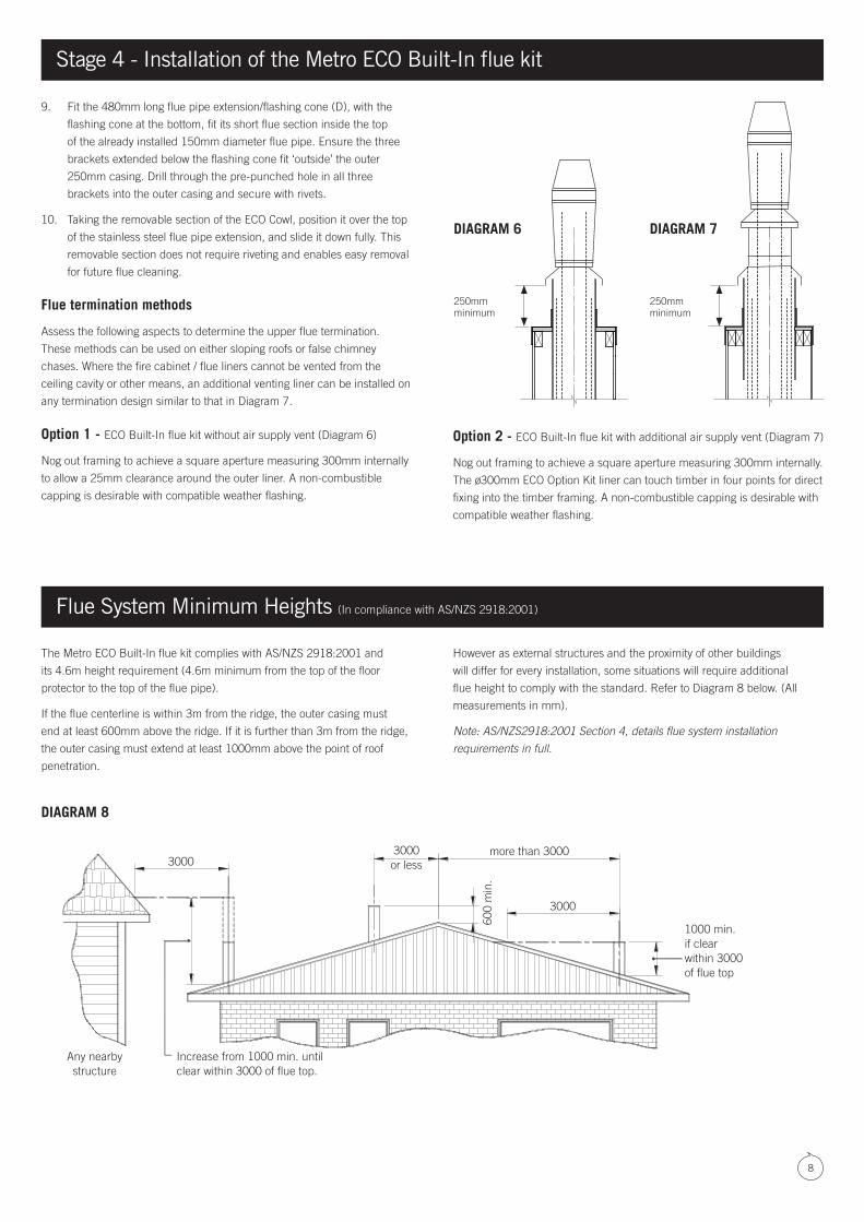
9. Fit the 480mm long flue pipe extension/flashing cone (D), with the
flashing cone at the bottom, fit its short flue section inside the top
of the already installed 150mm diameter flue pipe. Ensure the three
brackets extended below the flashing cone fit ‘outside’ the outer
250mm casing. Drill through the pre-punched hole in all three
brackets into the outer casing and secure with rivets.
10. Taking the removable section of the ECO Cowl, position it over the top
of the stainless steel flue pipe extension, and slide it down fully. This
removable section does not require riveting and enables easy removal
for future flue cleaning.
Flue termination methods
Assess the following aspects to determine the upper flue termination.
These methods can be used on either sloping roofs or false chimney
chases. Where the fire cabinet / flue liners cannot be vented from the
ceiling cavity or other means, an additional venting liner can be installed on
any termination design similar to that in Diagram 7.
Option 1 - ECO Built-In flue kit without air supply vent (Diagram 6)
Nog out framing to achieve a square aperture measuring 300mm internally
to allow a 25mm clearance around the outer liner. A non-combustible
capping is desirable with compatible weather flashing.
Option 2 - ECO Built-In flue kit with additional air supply vent (Diagram 7)
Nog out framing to achieve a square aperture measuring 300mm internally.
The ø300mm ECO Option Kit liner can touch timber in four points for direct
fixing into the timber framing. A non-combustible capping is desirable with
compatible weather flashing.
The Metro ECO Built-In flue kit complies with AS/NZS 2918:2001 and
its 4.6m height requirement (4.6m minimum from the top of the floor
protector to the top of the flue pipe).
If the flue centerline is within 3m from the ridge, the outer casing must
end at least 600mm above the ridge. If it is further than 3m from the ridge,
the outer casing must extend at least 1000mm above the point of roof
penetration.
However as external structures and the proximity of other buildings
will differ for every installation, some situations will require additional
flue height to comply with the standard. Refer to Diagram 8 below. (All
measurements in mm).
Note: AS/NZS2918:2001 Section 4, details flue system installation
requirements in full.
Flue System Minimum Heights (In compliance with AS/NZS 2918:2001)
.
.
.
30003000 or less
more than 3000
1000 min. if clear within 3000 of flue top
Increase from 1000 min. until clear within 3000 of flue top.
Any nearby structure
3000
600
min
.
DIAGRAM 8
250mm minimum
DIAGRAM 6 DIAGRAM 7
250mm minimum

9
Stage 5 – Construction and installation of the floor protector (hearth)
Combustible Floor (Insulated Floor Protector)
All installations of the Metro Ultra Insert model in combination with a VZCC
onto a combustible floor require an insulated floor protector that complies
with AS/NZS 2918:2001 and this installation manual.
This Floor Protector must be a minimum width of 825mm and a minimum
overall depth of 440mm.
Minimum overall depth is the distance from the front of the wall lining
(behind the fascia) to the front point of the Floor Protectors non-
combustible surface. The Floor Protector must have an insulating rating
which is equal to or greater than 26mm thick Eterpan LD. Recommended
construction of tiles on 26mm thick Eterpan LD board or equivalent.
Non-combustible floor (Ash Floor Protector)
All installations of the Ultra Insert model in combination with a VZCC onto
a concrete or non combustible floor structure only require an ash hearth
floor protector that complies with AS/NZS 2918:2001 and this installation
manual. (See Diagrams 11 & 12 opposite).
If the floor structure in front of the installation is non combustible (e.g.
concrete) the floor protector may be omitted. However, if heat sensitive
floor coverings (e.g. carpet) are fitted it is still necessary to keep these clear
from the appliance to the minimum distances specified in the table below.
In this case, if tiles or similar are required for decorative purposes, they
can be fixed directly to the concrete floor. This will make the top of the floor
protector approximately flush with the floor covering. The tiled area must
project out a minimum of 440mm from the front of the wall lining (behind
the fascia) and must be a minimum width of 825mm.
Please note: You will need to raise the VZCC by the same amount as the
thickness of the tiles fixed to the concrete floor. (see Diagram 12)
To complete installation you will require the Ultra Insert Fascia Base Rail to
be fitted to the Ultra Fascia to conceal the VZCC mount runners.
For elevated installations, the floor protector may be installed after the wood
fire is in position as it does not extend into the enclosure. However, the floor
protectors rear edge must butt up against the non-combustible wall lining
below the heater, and the joint at that point must be sealed to prevent the
possibility of ember penetration.
ModelBuilt-In installation
Combustible floorBuilt-In installation Non combustible floor
Minimum width Minimum projection
Ultra Built-In
Insulated floor protector
Ash hearth floor protector
825mm 440mm
Insulating - recommended construction of tiles on 26mm thick Eterpan LD board or equivalent.
Floor protector construction
Installation of the Metro Ultra Insert into a VZCC elevates the firebox
and fascia by 45mm. To complete installation and conceal this
45mm space between the surface of the floor and the underside of
the fascia, Metro offer the following options:
• A Pine Insert insulated floor protector in a range of tile colours
• An Ultra Fascia Base Rail in either metallic black paint or gloss
black enamel finish.
CAUTION! Important Information

10
FASCIA BASE RAIL CONCEALS VZCC MOUNT RUNNERS(NON COMBUSTIBLE FLOOR ONLY)
TILED ASH FLOOR PROTECTOR (IN AND OUT OF ENCLOSURE
INSULATED FLOOR PROTECTOR CONCEALS VZCC MOUNT RUNNERS(ALL FLOOR TYPES)
FASCIA BASE RAIL CONCEALS VZCC MOUNT RUNNERS(NON COMBUSTIBLE FLOOR ONLY)
FASCIA BASE RAIL CONCEALS VZCC MOUNT RUNNERS(ASH HEARTH FLOOR PROTECTOR - ALL FLOOR TYPES)
Stud wall
Insert firebox
Ash floor protector
VZCC spigot adapter
Wall lining
NON COMBUSTIBLE FLOOR ONLY (Fascia base rail conceals mount runners)
VZCC
FASCIA BASE RAIL CONCEALS VZCC MOUNT RUNNERS(NON COMBUSTIBLE FLOOR ONLY)
TILED ASH FLOOR PROTECTOR (IN AND OUT OF ENCLOSURE
INSULATED FLOOR PROTECTOR CONCEALS VZCC MOUNT RUNNERS(ALL FLOOR TYPES)
FASCIA BASE RAIL CONCEALS VZCC MOUNT RUNNERS(NON COMBUSTIBLE FLOOR ONLY)
FASCIA BASE RAIL CONCEALS VZCC MOUNT RUNNERS(ASH HEARTH FLOOR PROTECTOR - ALL FLOOR TYPES)
Stage 5 – Construction and installation of the floor protector (hearth)
Stud wall ø250mm
ø200mm
ø150mm
Insert firebox
Insulated floor protector
VZCC spigot adapter
Wall lining
ALL FLOORING TYPES (Insulated floor protector conceals mount runners)
VZCC
Stud wall
Insert firebox
Insulated floor protector
VZCC spigot adapter
Wall lining
ALL FLOORING TYPES (ELEVATED INSTALL) (Fascia base rail conceals mount runners)
VZCC
FASCIA BASE RAIL CONCEALS VZCC MOUNT RUNNERS(NON COMBUSTIBLE FLOOR ONLY)
TILED ASH FLOOR PROTECTOR (IN AND OUT OF ENCLOSURE
INSULATED FLOOR PROTECTOR CONCEALS VZCC MOUNT RUNNERS(ALL FLOOR TYPES)
FASCIA BASE RAIL CONCEALS VZCC MOUNT RUNNERS(NON COMBUSTIBLE FLOOR ONLY)
FASCIA BASE RAIL CONCEALS VZCC MOUNT RUNNERS(ASH HEARTH FLOOR PROTECTOR - ALL FLOOR TYPES)
FASCIA BASE RAIL CONCEALS VZCC MOUNT RUNNERS(NON COMBUSTIBLE FLOOR ONLY)
TILED ASH FLOOR PROTECTOR (IN AND OUT OF ENCLOSURE
INSULATED FLOOR PROTECTOR CONCEALS VZCC MOUNT RUNNERS(ALL FLOOR TYPES)
FASCIA BASE RAIL CONCEALS VZCC MOUNT RUNNERS(NON COMBUSTIBLE FLOOR ONLY)
FASCIA BASE RAIL CONCEALS VZCC MOUNT RUNNERS(ASH HEARTH FLOOR PROTECTOR - ALL FLOOR TYPES)
Stud wall
Insert firebox
Ash floor protector
VZCC spigot adapter
Wall lining
NON COMBUSTIBLE FLOOR ONLY (Fascia base rail conceals mount runners)
VZCC
DIAGRAM 9 DIAGRAM 10
DIAGRAM 11 DIAGRAM 12
ø250mm
ø200mm
ø150mm
ø250mm
ø200mm
ø150mm
ø250mm
ø200mm
ø150mm
Fascia base rail
Fascia base railFascia base rail

11
Take care not to lift the fascia by the louvres as they can bend.
1. If you haven’t already fitted the door, do so now ensuring the spacer
washer is placed on top of the hinge pin as indicated in Diagram 13
(Inset A).
2. At this time ensure the fan unit is positioned with the grommets over
the location bolts at each end of the fan tray. Check the thermostat
plug is attached with wiring and lead kept away from the firebox. Any
excess lead must be shortened or positioned to the outside of heat
shields or cabinet. Ensure the fan rotates freely.
3. Rotate the door handle fully anti-clockwise prior to fitting the fascia.
4. To fit the fascia, ensure the four speed clips are positioned over
the large diameter mounting holes in the return folds of the cabinet
(fascia mount points). When attaching the fascia ensure to lift and
press the fascia Top Rail over the Top Panel of the cabinet. To allow
the fascia to fully swing into place, slightly press down the tensioned
heat shield above the fan so the fascia can fully contact the cabinet.
Attach the 4x fascia mounting screws (8g x 19mm) while positioning
the fascia evenly around the door.
5. The fascia should be evenly spaced around the door frame and sit
evenly against the wall lining when the firebox cabinet has been
correctly positioned. (The door can still be removed from the fire with
the fascia in place when it is correctly fitted).
6. Open the door and remove the two nuts and air slide guide washers
to enable placement of the air slide. The air slide feeds ‘lever end’ first
behind the fascia and through the lever slot. Fit the guide washers
and nuts and ensure the slide moves freely with the lever resting
gently on the fascia slot.
7. The air control knob can now be fitted.
Mantel clearance
A timber or combustible mantel must not project more than 150mm from
the finished wall lining and there must be a minimum distance of 450mm
above the top of the Ultra Insert fascia to the underside of the mantel. If the
clearance is less than the minimum specified, a heat shield will be required
to be fitted under the mantelshelf in accordance with AS/NZS 2918:2001.
Mantle uprights/columns must be a minimum clearance of 180mm from
the side of the fascia and project no more than 100mm from the wall lining.
Stage 6 - Fascia fitment
Mantle shelf (maximum projection 150mm)
450mm minimum
180mm minimum
Man
tle c
olum
n
Fascia
Insert Cabinet
Fixing Points For Seismic Restraint
Speed clip x4
Air Control Knob
Spacer Washer
Hinge Pin
DIAGRAM 13
A
Cable Clamp Slot