Embed Size (px)
Citation preview
1-800-634-7328 DirectSupply.com
Attendant®
CONNECTED VITAL SIGNS MONITOR
AVSM2
Please keep and refer to this Owner’s Manual.
Owner’s Manual
Thank you for purchasing an Attendant® Connected Vital Signs Monitor from Direct Supply Equipment & Furnishings®, a
division of Direct Supply, Inc. Please read this entire manual carefully and keep it for future reference. This manual will
provide you with instructions, warnings, warranty information and other important information about your device. Share this
information with your housekeeping, nursing and maintenance staff to help ensure the device is cared for properly.
2
Table of Contents
Table of ContentsContents .......................................................................................................................2 - 3
Introduction .................................................................................................................4 - 5 Definitions & Symbols ....................................................................................................4 Intended Use for the AVSM2 ..........................................................................................4 Indications for Use ..........................................................................................................4 About This Manual ..........................................................................................................5 Identifying the AVSM2 Configurations ............................................................................5 Features for the AVSM2 ..................................................................................................5 Safety Information .......................................................................................................6 - 8 General Safety Information .............................................................................................6 Warnings ....................................................................................................................6 - 7 Cautions ..........................................................................................................................8 Description of the Monitor .......................................................................................9 - 17 Front Panel Components ......................................................................................... 9 - 11 Rear Panel Components ........................................................................................ 12 - 13 Left Panel Components................................................................................................. 13 Right Panel Components ....................................................................................... 14 - 15 Displays .................................................................................................................. 16 - 17Setting Up the Monitor ...........................................................................................18 - 21 Unpacking & Inspection ................................................................................................ 18 List of Components ...................................................................................................... 19 Power Cable Connections ...................................................................................... 19 - 20 Measurement Cable Connections ................................................................................21Battery Operation ....................................................................................................22 - 24 Operating the Monitor on Battery Power ...............................................................22 - 23 Battery Status Indication ...............................................................................................23 Charging a Low Battery .................................................................................................24Using the Monitor ...................................................................................................25 - 30 Overview of Mode ........................................................................................................25 Turning the Monitor On & Off ................................................................................25 - 27 Setting Date & Time ......................................................................................................27 Setting Resident Type ....................................................................................................28 Setting NIBP Units .................................................................................................28 - 29 Setting Temperature Units & Modes .............................................................................29 Setting Pulse Tone Volume ............................................................................................30 Setting Alarm Volume ....................................................................................................30Alarms & Limits .......................................................................................................31 - 41 General ..........................................................................................................................31 Alarm Priority ................................................................................................................31 Visual & Audible Alarm Indication ..........................................................................31 - 33 Verifying Visual & Audible Alarm Indication ...................................................................33 Changing Alarm Limits ..................................................................................................33 Alarm Audio Paused ...............................................................................................33 - 41 NIBP Monitoring ......................................................................................................42 - 48 General ..........................................................................................................................43 Setup Connections ........................................................................................................44 NIBP Measurement Modes ..........................................................................................45 Description of NIBP Menu Functions .....................................................................45 - 48SpO2 Monitoring ......................................................................................................49 - 52 General ..........................................................................................................................50 Setup Connections ........................................................................................................51 Description of SpO2 Menu Functions ............................................................................52 Description of Pulse Rate Operation .............................................................................52
31-800-634-7328 DirectSupply.com
Temperature Monitoring .........................................................................................53 - 59 General ..........................................................................................................................53 Temperature Measurement Modes ..............................................................................53 Measurement Method ...........................................................................................53 - 57 Description of Temperature Menu Functions .........................................................57 - 59 Trends .......................................................................................................................60 - 61 General ..........................................................................................................................60 Trend Data Printout .......................................................................................................60 Displaying Stored Resident Data ..................................................................................60 Erasing Resident Data ...................................................................................................60 Trend Data Download .............................................................................................60 - 61Menu Structure ...............................................................................................................62
Printing .....................................................................................................................63 - 67 General ..........................................................................................................................63 Setting Manual or Stream Printing Type .................................................................63 - 64 Printing Resident Data (Manual Mode) ..................................................................64 - 67 External Interface .....................................................................................................68 - 69 General ..........................................................................................................................68 Cable Connection ...................................................................................................68 - 69 Nurse Call Interface ......................................................................................................69Maintenance ............................................................................................................70 - 72 Recycling & Disposal.....................................................................................................70 Returning the Monitor & System Components.............................................................70 Service ..........................................................................................................................70 Periodic Safety Checks ..................................................................................................70 Cleaning ........................................................................................................................70 Battery Maintenance .....................................................................................................71 Loading Printer Paper ....................................................................................................72 Troubleshooting .......................................................................................................73 - 75 General ..........................................................................................................................73 Corrective Action .................................................................................................... 73 - 74 EMI (Electromagnetic Interference) ..............................................................................75 Obtaining Technical Assistance .....................................................................................75 Factory Defaults .......................................................................................................76 - 77 General .......................................................................................................................... 76 Parameter Ranges & Default Settings ................................................................... 76 - 77 Specification ............................................................................................................78 - 89 Display ..........................................................................................................................78 Controls .........................................................................................................................78 Alarms ...........................................................................................................................78 Physical Characteristics & Printer .................................................................................78 Electrical ........................................................................................................................79 Environmental Conditions .............................................................................................79 Tone Definition ..............................................................................................................80 Measurement Parameters .....................................................................................81 - 82 Internal Memory ...........................................................................................................83 Compliance ............................................................................................................83 - 86 Manufacturer’s EMC Declaration ...........................................................................87 - 89Limited Warranty ............................................................................................................90
Customer Service ...........................................................................................................91
4
Introduction
The content of this manual is subject to change without notice.
Contact Direct Supply with any questions you might have.
Definitions & SymbolsNOTE: Indicates a helpful tip.
CAUTION: Indicates correct operating or maintenance procedures in order to prevent damage to or destruction of the equipment or other property.
WARNING: Calls attention to a potential danger that requires correct procedures or practices in order to prevent personal injury.
•: Attention! Read the instructions.
MONITOR or Device: Your Attendant® Connected Vital Signs Monitor AVSM2.
YOU and YOUR: The facility, community or other person or entity that has purchased the product.
WE, US, and OUR: Direct Supply Manufacturing, Inc.
Intended Use for the AVSM2
The monitor is intended to be used to monitor noninvasive blood pressure (NIBP), functional arterial oxygen saturation (SpO2), pulse rate (PR), temperature (Temp) for adult, pediatric and neonatal residents in all areas of a hospital and hospital-type facilities. Monitor users should be skilled at the level of a technician, doctor, nurse or medical specialist. The monitor is suitable for continuous operation.
NOTE: Hospital use typically includes areas such as general care floors, operating rooms, special procedure areas, and intensive and critical care areas within the hospital. Hospital-type facilities include physician office-based facilities, sleep labs, Skilled Nursing facilities, surgical centers and subacute care centers.
NOTE: Medically skilled and trained users can be clinicians, like doctors and nurses, who know how to take and interpret a resident’s vital signs. These clinicians must take direct responsibility for the resident’s life. They include caregivers or medically trained interpreters who are authorized under the appropriate clinical facility procedures to support resident care. Any inappropriate setting, especially the alarm limit or alarm notification settings, can lead to a hazardous situation that injures the resident, harms the resident or threatens the resident’s life. This equipment should only be operated by trained users who can adjust the settings of the vital signs monitor.
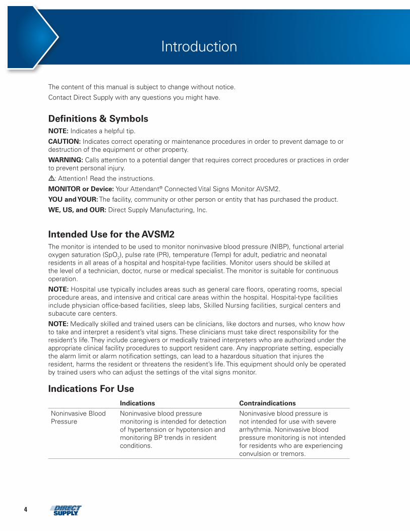
Indications For Use Indications Contraindications
Noninvasive Blood Pressure
Noninvasive blood pressure monitoring is intended for detection of hypertension or hypotension and monitoring BP trends in resident conditions.
Noninvasive blood pressure is not intended for use with severe arrhythmia. Noninvasive blood pressure monitoring is not intended for residents who are experiencing convulsion or tremors.
51-800-634-7328 DirectSupply.com
Pulse Oximetry Pulse oximetry monitoring is intended to be used to monitor functional arterial oxygen saturation and pulse rate.
Pulse oximetry monitoring is not intended for use with severe peripheral vascular disease and severe anemia (decreased Hemoglobin).
Temperature Temperature monitoring is indicated for use in residents who require continuous monitoring of body temperature.
No known contraindications.
About This Manual This manual explains how to set up and use the monitor. Read the entire manual, including the Safety Information section, before you operate the monitor.
Identifying the AVSM2 Configurations The following table identifies AVSM2 configurations and how they are indicated. The reference number and serial number are located on the bottom of the monitor.
All information in this manual, including the illustrations, is based on the monitor configured with the Battery, SpO2 module, Printer module, Turbo Temp or Genius 2 thermometer. If the relevant functions do not exist, please verify your unit configuration.
Description
AVSM2 with SpO2, A&D blood pressure, Turbo Temp oral thermometer
AVSM2 with SpO2, A&D blood pressure, Genius 2 tympanic thermometer
AVSM2 with Printer, SpO2, A&D blood pressure, Turbo Temp oral thermometer
Features for the AVSM2
Physical The monitor is lightweight and compact, measuring 249 × 211 × 154 (mm) (W × H × D) and weighting 3 kg. Its carrying handle is designed for transport while operating on battery power.
Electrical The monitor is powered by an internal battery pack that typically provides 8 hours of monitoring from a fully charged new battery. The batteries are continuously recharged when the monitor is connected to an AC power source. Refer to the Battery Operation section for details.
Display The monitor display is a 7-segment LED that shows numeric resident information as well as status conditions.
Auxiliary Input/Output(s)
The monitor provides USB and RJ11 ports as standard outputs. An external communications port and a Bluetooth module are also available as optional outputs.
6
General Safety Information
This section contains important safety information related to general use of the AVSM2. Other important safety information appears throughout the manual.
Important! Before use, carefully read this manual and all accessory manuals for use, as well as all precautionary information and specifications.
Software Safety InformationThis monitor contains software and optionally supports two external communication protocols (LAN/Bluetooth).
User Requirements• Please contact Direct Supply if unintentional equipment changes or attacks from outside are
discovered.• Please erase any patient data contained within the monitor before disposing of the monitor. This
will prevent any unintentional data leaks. Refer to the TRENDS section of this manual for details on erasing patient data.
AuthorizationFirmware updates, trend data downloads, and wireless connections can only be performed by authorized personnel via Service Mode.
Software Integrity to Prevent MalwareThe monitor checks the program checksum during the Power-On Self-Test (POST) in addition to testing monitor circuitry and functions. These tests check for unintentional software changes from malware. Refer to the USING THE MONITOR section for more details.
EncryptionTrend data is encrypted to prevent personal data leaks, data interception and data manipulation. Refer to the TRENDS section for more details.
Warnings
• WARNING: Do not take or use the monitor in locations where highly combustible anesthetics or flammable gases are used, or in high-pressure oxygen rooms or inside oxygen tents, as this may cause a flammable explosion.
• WARNING: When using the monitor with a commercial electric power source, use the monitor with an electric power wall socket with a grounding wire for medical use. Not doing so could cause electric shock.
• WARNING: Do not connect grounding wire to gas pipes. This could cause fire.
• WARNING: Only doctors and officially certified personnel should use this monitor. Do not allow residents or others to touch this monitor. Doing so could cause accidents.
• WARNING: This monitor cannot be used when an MRI is in progress. If an MRI is in use, keep attachments away from residents to prevent accidents.
• WARNING: The monitor conforms to the requirements of the EMC standard (IEC60601-1-2) and may therefore be used simultaneously with pacemakers and other electrical simulators. It should, however, be noted that the monitor may be affected by electrical scalpels and microwave therapeutic apparatus. Please check operation of the monitor during and after use of such equipment.
Safety Information
71-800-634-7328 DirectSupply.com
• WARNING: Mobile phones or transceivers may cause interference with this monitor.
• WARNING: Do not use any unauthorized accessories or options.
• WARNING: Thoroughly read the instruction manuals supplied with accessories and options to ensure correct use. This instruction manual does not carry the caution selections for such equipment.
• WARNING: Do not open cover or disassemble this monitor. Doing so could cause electric shock or fire. It is prohibited by law to modify the monitor without authorization.
• WARNING: Do not use power source other than the specified voltage (100 - 240V~50/60Hz), as this may cause fire or electric shock.
• WARNING: Pre-use inspection and preventive maintenance must be performed.
• WARNING: This monitor is protected against the discharge of a defibrillator. However, do not touch the monitor when a defibrillator is being discharged (electrified), as doing so may cause electric shock.
• WARNING: When connecting the monitor with other equipment: 1. Ensure the connected equipment is in accordance with the IEC60601-1 or IEC safety standards so
the system complies with IEC60601-1. 2. Employ additional protective measures (e.g. additional protective earthing) as necessary.
• WARNING: Do not connect devices that do not meet medical safety standards, such as commercial PCs, as they may cause electric shock. This monitor meets the restricted level of leakage required for medical devices. Therefore, this monitor cannot be connected to a device that would give a combined total of leakage beyond the restricted level.
• WARNING: Please contact Direct Supply if unintentional equipment changes or attacks from outside are discovered.
• WARNING: Do not place anything on top of this monitor. If something is spilled on the monitor or gets into it, such spillage may cause fire or electric shock. If fluid spills on the monitor accidentally, disconnect the power cord, wipe dry immediately and have the monitor serviced to make sure no hazard exists.
• WARNING: Do not place heavy objects on the power cord, as doing so may cause fire or electric shock.
• WARNING: Before conducting maintenance work, turn the power OFF and unplug the power cord from the wall socket to prevent electric shock.
• WARNING: If the following occur, turn the power OFF immediately and unplug the power cord from the wall socket. Continued use in such situations may cause fire or electric shock. • There is smoke or a strange odor leaking out of the monitor. • The monitor has been dropped or impacted by an object. • Liquid or foreign matter gets inside the monitor. • Device failure has occurred. Also, if any of the above occurs, promptly do the following: 1. Check to see that the power cord has been unplugged from the wall socket. 2. Place an “Out of Order” sign on the monitor and do not use it.
• WARNING: Do not connect more than one resident to the monitor at the same time. Do not connect more than one monitor to a resident.
• WARNING: The vital signs monitor is a prescription device and is to be operated by qualified personnel only.
• WARNING: As with any medical equipment, carefully route resident cabling to reduce the possibility of resident entanglement or strangulation.
• WARNING: Never lift the monitor by the sensor cable, blood pressure hose, power cord or any other accessory. Such accessories could detach, causing the monitor to fall on the resident.
8
Safety Information (cont.)
• WARNING: Do not position the monitor so it is difficult to operate the disconnection device when a separable plug is used as isolation.
• WARNING: Do not touch signal input, signal output or other connectors and the resident simultaneously.
• WARNING: Do not cover the vent holes.
• WARNING: This monitor may not be appropriate for all residents. Other devices may be required. A licensed healthcare practitioner should determine whether this monitor is suitable for use with each particular resident.
• WARNING: Resident conditions may result in erroneous readings. If the measurements are suspect, verify the reading using another clinically accepted measurement method.
• WARNING: This monitor contains ferromagnetic materials. Do not use this monitor in a magnetic resonance imaging (MRI) room or in proximity to an MRI device. Doing so may result in damage to the monitor or injury to the resident.
CautionsCaution statements identify conditions or practices that could result in damage to the equipment or other property.
• CAUTION: Federal law restricts this device to sale by or on the order of a physician.
• CAUTION: The monitor may not operate properly if it is operated or stored at conditions outside the ranges stated in this manual, or subjected to excessive shock or dropping.
• CAUTION: When connecting the monitor to any instrument, verify proper operation before clinical use. Both the monitor and the instrument connected to it must be connected to a grounded outlet.
• CAUTION: Accessory equipment connected to the monitor’s data interface must be certified according to IEC60950 for data-processing equipment or IEC60601-1 for electromedical equipment. All combinations of equipment must be in compliance with IEC60601-1 system requirements. Anyone who connects additional equipment to the signal input or signal output port configures a medical system and is therefore responsible that the system complies with the requirements of IEC 60601-1 and the electromagnetic compatibility system standard IEC60601-1-2. If in doubt, consult Direct Supply.
• CAUTION: Risk of explosion if battery is replaced with an incorrect type.
• CAUTION: When the integrity of the external protective conductor in the installation or its arrangement is in doubt, equipment shall be operated from its internal electrical power source.
• CAUTION: Do not rely entirely on the monitor readings for clinical assessment.
• CAUTION: Pulling the cable could cause the disconnection of the cable from the monitor and can cause an error for the measurement.
91-800-634-7328 DirectSupply.com
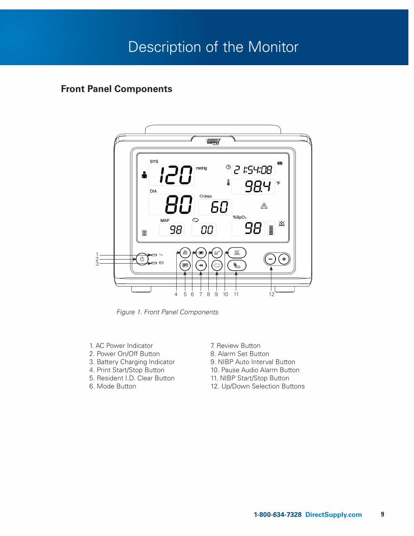
Front Panel Components
Description of the Monitor
1. AC Power Indicator 7. Review Button 2. Power On/Off Button 8. Alarm Set Button 3. Battery Charging Indicator 9. NIBP Auto Interval Button 4. Print Start/Stop Button 10. Pause Audio Alarm Button 5. Resident I.D. Clear Button 11. NIBP Start/Stop Button 6. Mode Button 12. Up/Down Selection Buttons
4
Figure 1. Front Panel Components
5 6 7 8 9 10 11 12
123
10
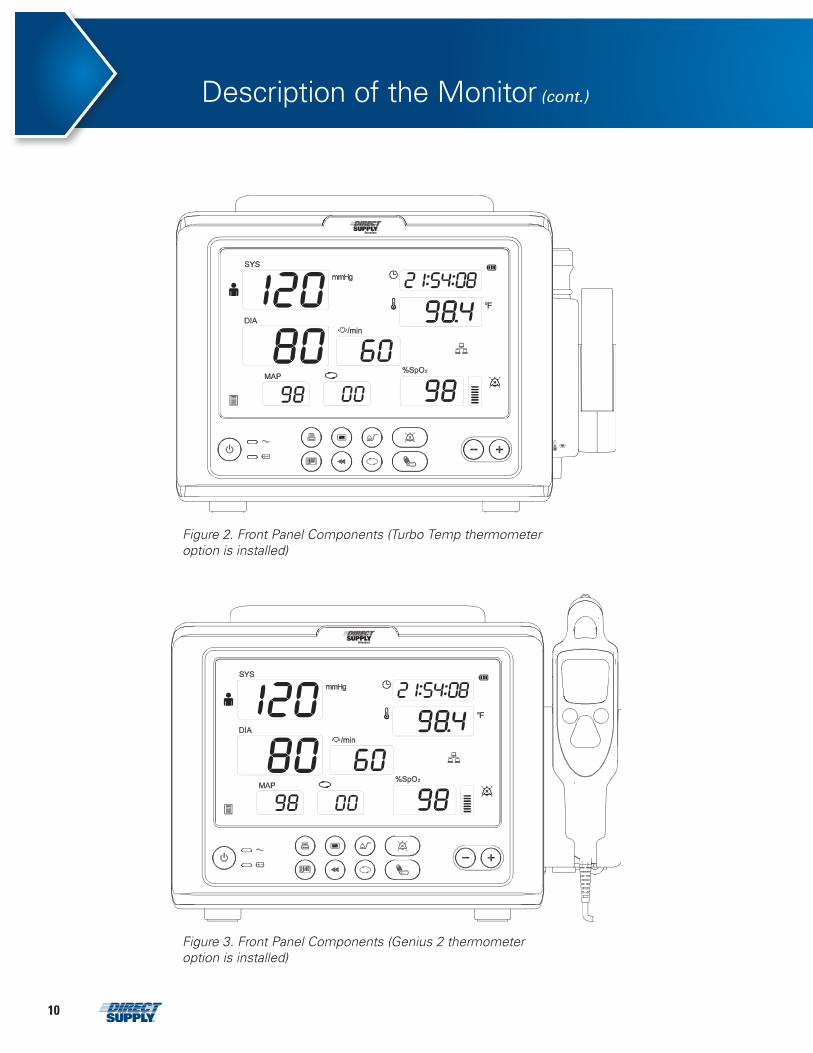
Figure 2. Front Panel Components (Turbo Temp thermometer option is installed)
Figure 3. Front Panel Components (Genius 2 thermometer option is installed)
Description of the Monitor (cont.)
111-800-634-7328 DirectSupply.com
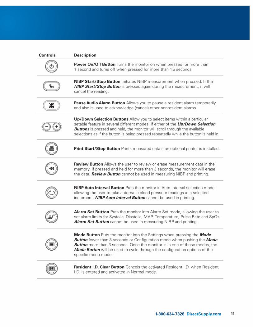
Controls Description
Power On/Off Button Turns the monitor on when pressed for more than 1 second and turns off when pressed for more than 1.5 seconds.
NIBP Start/Stop Button Initiates NIBP measurement when pressed. If the NIBP Start/Stop Button is pressed again during the measurement, it will cancel the reading.
Pause Audio Alarm Button Allows you to pause a resident alarm temporarily and also is used to acknowledge (cancel) other nonresident alarms.
Up/Down Selection Buttons Allow you to select items within a particular setable feature in several different modes. If either of the Up/Down Selection Buttons is pressed and held, the monitor will scroll through the available selections as if the button is being pressed repeatedly while the button is held in.
Print Start/Stop Button Prints measured data if an optional printer is installed.
Review Button Allows the user to review or erase measurement data in the memory. If pressed and held for more than 3 seconds, the monitor will erase the data. Review Button cannot be used in measuring NIBP and printing.
NIBP Auto Interval Button Puts the monitor in Auto Interval selection mode, allowing the user to take automatic blood pressure readings at a selected increment. NIBP Auto Interval Button cannot be used in printing.
Alarm Set Button Puts the monitor into Alarm Set mode, allowing the user to set alarm limits for Systolic, Diastolic, MAP, Temperature, Pulse Rate and SpO2. Alarm Set Button cannot be used in measuring NIBP and printing.
Mode Button Puts the monitor into the Settings when pressing the Mode Button fewer than 3 seconds or Configuration mode when pushing the Mode Button more than 3 seconds. Once the monitor is in one of these modes, the Mode Button will be used to cycle through the configuration options of the specific menu mode.
Resident I.D. Clear Button Cancels the activated Resident I.D. when Resident I.D. is entered and activated in Normal mode.
12
Description of the Monitor (cont.)
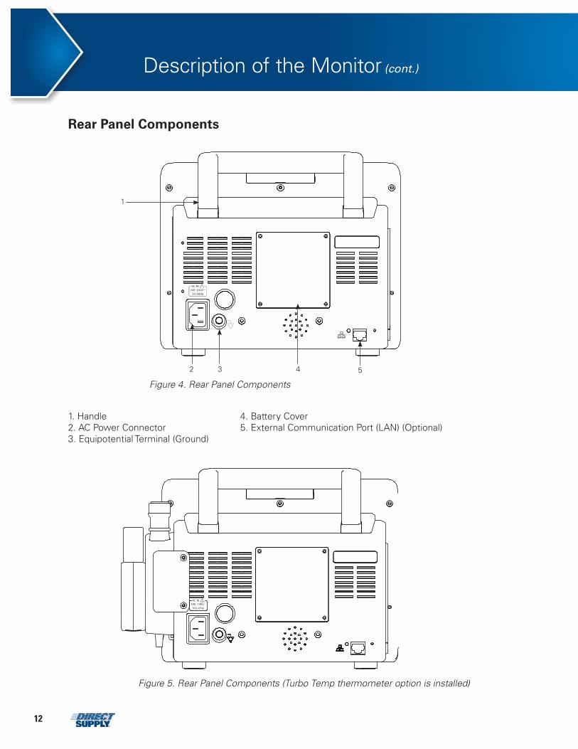
Rear Panel Components
1. Handle 4. Battery Cover 2. AC Power Connector 5. External Communication Port (LAN) (Optional)3. Equipotential Terminal (Ground)
Figure 4. Rear Panel Components
1
2 3 4 5
Figure 5. Rear Panel Components (Turbo Temp thermometer option is installed)
131-800-634-7328 DirectSupply.com
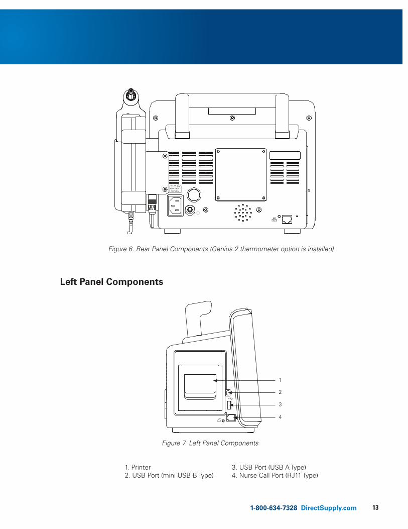
Figure 6. Rear Panel Components (Genius 2 thermometer option is installed)
Left Panel Components
1
2
3
4
1. Printer 2. USB Port (mini USB B Type)
3. USB Port (USB A Type) 4. Nurse Call Port (RJ11 Type)
Figure 7. Left Panel Components
14
Description of the Monitor (cont.)
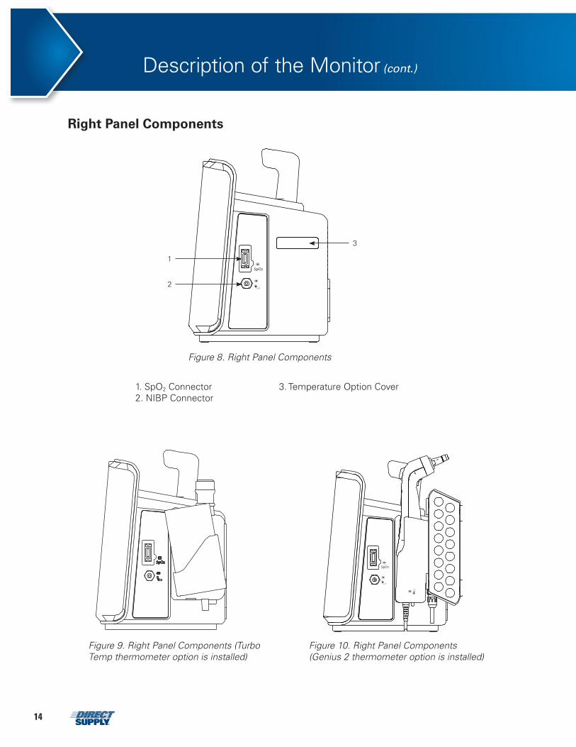
Right Panel Components
1. SpO2 Connector 2. NIBP Connector
3. Temperature Option Cover
Figure 8. Right Panel Components
3
1
2
Figure 9. Right Panel Components (Turbo Temp thermometer option is installed)
Figure 10. Right Panel Components (Genius 2 thermometer option is installed)
151-800-634-7328 DirectSupply.com
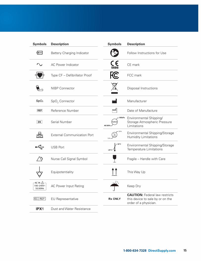
Symbols Description Symbols Description
Battery Charging Indicator
Follow Instructions for Use
AC Power Indicator CE mark
Type CF – Defibrillator Proof FCC mark
NIBP Connector
Disposal Instructions
SpO2 Connector
Manufacturer
Reference Number
Date of Manufacture
Serial Number 46.5kPa
105kPa Environmental Shipping/Storage Atmospheric Pressure Limitations
External Communication Port
Environmental Shipping/Storage Humidity Limitations
USB Port
Environmental Shipping/Storage Temperature Limitations
Nurse Call Signal Symbol
Fragile – Handle with Care
Equipotentiality
This Way Up
AC Power Input Rating Keep Dry
EU Representative
CAUTION: Federal law restricts this device to sale by or on the order of a physician.
Dust and Water Resistance
16
Description of the Monitor (cont.)
Displays
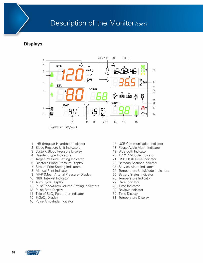
1 IHB (Irregular Heartbeat) Indicator 17 USB Communication Indicator 2 Blood Pressure Unit Indicators 18 Pause Audio Alarm Indicator 3 Systolic Blood Pressure Display 19 Bluetooth Indicator 4 Resident Type Indicators 20 TCP/IP Module Indicator 5 Target Pressure Setting Indicator 21 USB Flash Drive Indicator 6 Diastolic Blood Pressure Display 22 Barcode Scanner Indicator 7 Stream Print Setting Indicators 23 Service Mode Indicator 8 Manual Print Indicator 24 Temperature Unit/Mode Indicators9 MAP (Mean Arterial Pressure) Display 25 Battery Status Indicator
10 NIBP Interval Indicator 26 Temperature Indicator11 Auto Cycle Display 27 Date Indicator12 Pulse Tone/Alarm Volume Setting Indicators 28 Time Indicator13 Pulse Rate Display 29 Review Indicator14 Title of SpO2 Parameter Indicator 30 Time Display15 %SpO2 Display 31 Temperature Display16 Pulse Amplitude Indicator
12
3
4
5
6
7
8
10 11 12 13 14 15 16
17
18
1920
212223
24
25
313029282726
Figure 11. Displays9
171-800-634-7328 DirectSupply.com
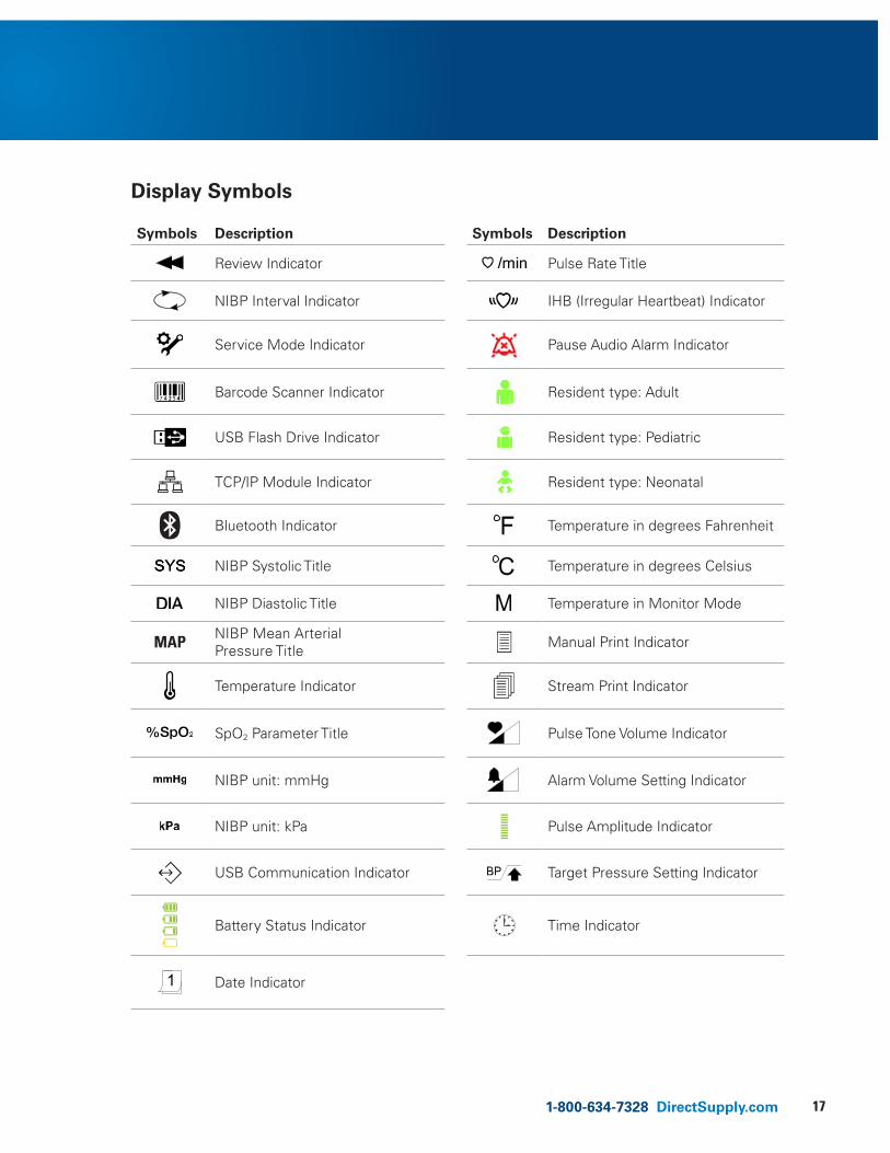
Symbols Description Symbols Description
Review Indicator
Pulse Rate Title
NIBP Interval Indicator
IHB (Irregular Heartbeat) Indicator
Service Mode Indicator
Pause Audio Alarm Indicator
Barcode Scanner Indicator
Resident type: Adult
USB Flash Drive Indicator
Resident type: Pediatric
TCP/IP Module Indicator
Resident type: Neonatal
Bluetooth Indicator
Temperature in degrees Fahrenheit
NIBP Systolic Title
Temperature in degrees Celsius
NIBP Diastolic Title
Temperature in Monitor Mode
MAP NIBP Mean Arterial Pressure Title
Manual Print Indicator
Temperature Indicator
Stream Print Indicator
SpO2 Parameter Title
Pulse Tone Volume Indicator
NIBP unit: mmHg
Alarm Volume Setting Indicator
NIBP unit: kPa
Pulse Amplitude Indicator
USB Communication Indicator
Target Pressure Setting Indicator
Battery Status Indicator
Time Indicator
Date Indicator
Display Symbols
18
Setting Up the Monitor
• WARNING: To help ensure accurate performance and prevent device failure, do not expose the monitor to extreme moisture, including direct exposure to rain or liquid. Such exposure may cause inaccurate performance or device failure. Refer to Specification section.
• WARNING: The monitor should not be used adjacent to or stacked with other equipment. If adjacent or stacked use is necessary, the monitor should be tested and verified to operate properly prior to using it in that in configuration.
• WARNING: Make sure that the monitor speaker is not obstructed. Failure to do so could result in an inaudible alarm tone.
• CAUTION: Recharging the battery is strongly recommended when the battery has not been recharged for 3 or more months.
• CAUTION: Recharging the battery is strongly recommended before using the monitor.
• CAUTION: Follow local government ordinances and recycling instructions regarding disposal or recycling of device components, including battery.
• CAUTION: If the case appears damaged, do not use the monitor and contact Direct Supply.
Unpacking & InspectionThe monitor is shipped in one carton. Examine the carton carefully for evidence of damage. Contact Direct Supply immediately if any damage is discovered. Refer to the Maintenance section for instructions on returning damaged items.
NOTE: Refer to the Performance Verification section in the owner’s manual for detailed information.
Set the monitor to the user’s intended position where the user can easily recognize the visual and audible monitoring conditions. Normally it is recommended to set at a distance of 1 m from the user. Optimal viewpoint is at any point within the base of a cone by an angle of 30° to the center of the monitoring display.
If no sound is heard after pressing any of the buttons on the monitor, or pressing a button does not result in the appropriate function being initiated, contact Direct Supply.
191-800-634-7328 DirectSupply.com
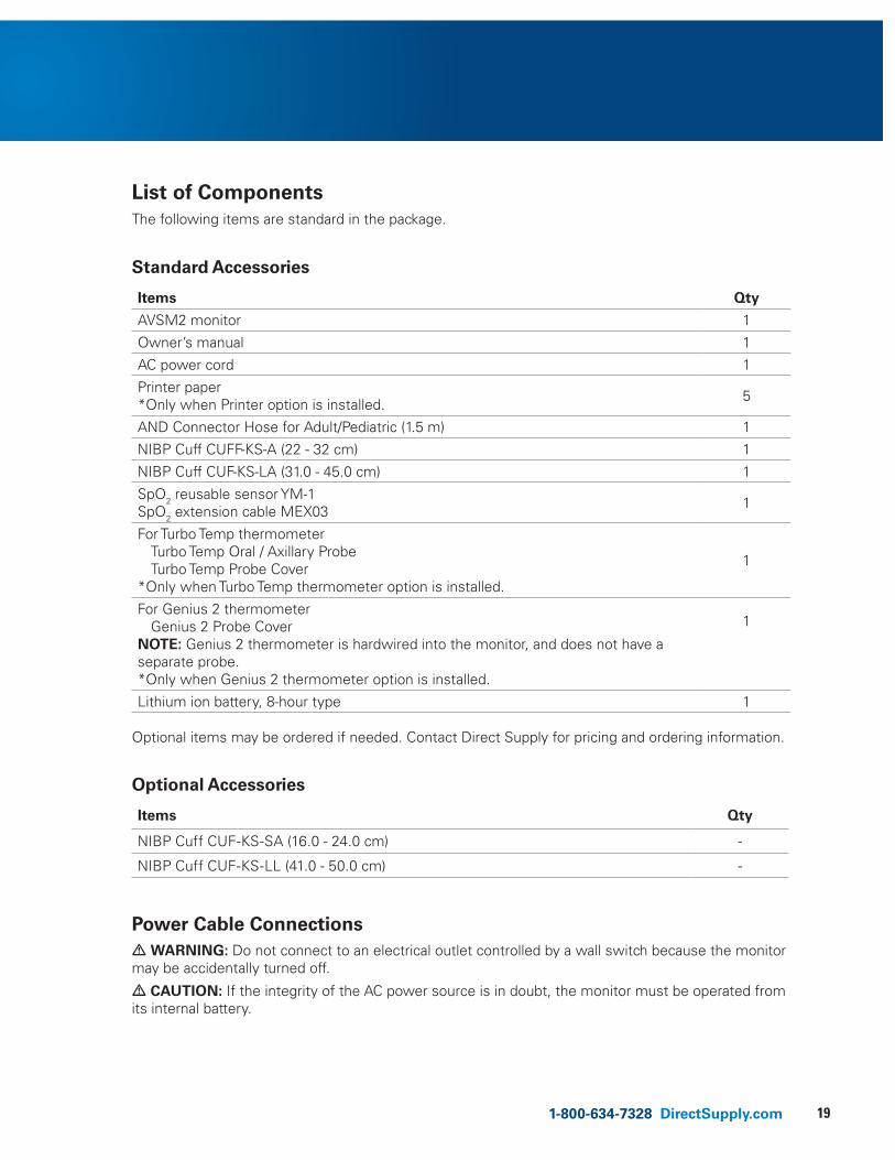
List of ComponentsThe following items are standard in the package.
Standard Accessories
Items Qty
AVSM2 monitor 1
Owner’s manual 1
AC power cord 1
Printer paper *Only when Printer option is installed. 5
AND Connector Hose for Adult/Pediatric (1.5 m) 1
NIBP Cuff CUFF-KS-A (22 - 32 cm) 1
NIBP Cuff CUF-KS-LA (31.0 - 45.0 cm) 1
SpO2 reusable sensor YM-1SpO2 extension cable MEX03 1
For Turbo Temp thermometer Turbo Temp Oral / Axillary ProbeTurbo Temp Probe Cover
*Only when Turbo Temp thermometer option is installed.
1
For Genius 2 thermometer Genius 2 Probe Cover
NOTE: Genius 2 thermometer is hardwired into the monitor, and does not have a separate probe.*Only when Genius 2 thermometer option is installed.
1
Lithium ion battery, 8-hour type 1
Optional items may be ordered if needed. Contact Direct Supply for pricing and ordering information.
Optional Accessories
Items Qty
NIBP Cuff CUF-KS-SA (16.0 - 24.0 cm) -
NIBP Cuff CUF-KS-LL (41.0 - 50.0 cm) -
Power Cable Connections• WARNING: Do not connect to an electrical outlet controlled by a wall switch because the monitor may be accidentally turned off.
• CAUTION: If the integrity of the AC power source is in doubt, the monitor must be operated from its internal battery.
20
Setting Up the Monitor (cont.)
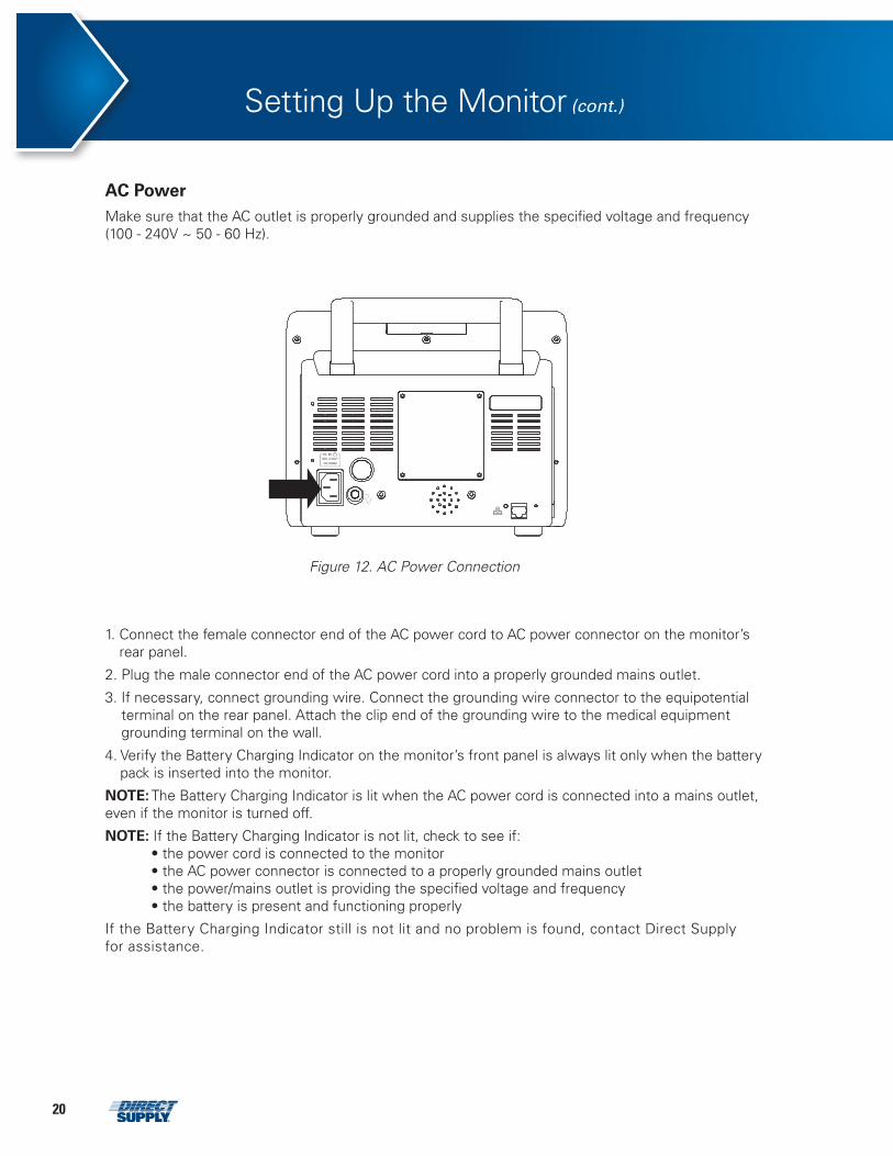
AC Power Make sure that the AC outlet is properly grounded and supplies the specified voltage and frequency (100 - 240V ~ 50 - 60 Hz).
Figure 12. AC Power Connection
1. Connect the female connector end of the AC power cord to AC power connector on the monitor’s rear panel.
2. Plug the male connector end of the AC power cord into a properly grounded mains outlet.
3. If necessary, connect grounding wire. Connect the grounding wire connector to the equipotential terminal on the rear panel. Attach the clip end of the grounding wire to the medical equipment grounding terminal on the wall.
4. Verify the Battery Charging Indicator on the monitor’s front panel is always lit only when the battery pack is inserted into the monitor.
NOTE: The Battery Charging Indicator is lit when the AC power cord is connected into a mains outlet, even if the monitor is turned off.
NOTE: If the Battery Charging Indicator is not lit, check to see if: • the power cord is connected to the monitor • the AC power connector is connected to a properly grounded mains outlet • the power/mains outlet is providing the specified voltage and frequency• the battery is present and functioning properly
If the Battery Charging Indicator still is not lit and no problem is found, contact Direct Supply for assistance.
211-800-634-7328 DirectSupply.com
Measurement Cable Connections• WARNING: Use only accessories intended for use with this monitor. Use accessories according to the manufacturer’s directions for use and your facility’s standards. Use only accessories that have passed the recommended biocompatibility testing in compliance with ISO10993-1.
NOTE: Both frequent checks by the operator on a daily basis and more comprehensive technical checks less frequently are required in order to detect mechanical damage to the monitor, damage to cables, etc.
NIBP Hoses and Cuffs
1. Select an appropriate size cuff for the resident. (Refer to the NIBP Monitoring section.)
2. Connect the hose to the “NIBP” connector making sure to tighten the connector. (See Figure 8.)
3. Attach the cuff to the end of the hose.
SpO2 Cables and Sensors
1. Select an appropriate sensor for the resident and desired application. (Refer to the SpO2 Monitoring section.)
2. Connect the extension cable to the “SpO2” connector on the monitor’s right panel. (See Figure 8.)
3. Attach the sensor to the end of the cable.
Thermometers
1. Select the appropriate thermometer(s) for the desired application. (Turbo Temp thermometer or Genius 2 thermometer)
2. Connect the temperature probes to the Temperature probe connector on the monitor’s right panel. (See Figure 8.)

22
Battery Operation
• WARNING: The Battery Charging Indicator is used to acknowledge the absence of an installed battery. If the monitor is plugged into an AC outlet without the battery installed, the Battery Charging Indicator will not light up.
• CAUTION: Recharging the battery is strongly recommended when it has not been fully recharged for 3 or more months.
• CAUTION: Recharging the battery is strongly recommended before using the monitor.
• CAUTION: When the voltage of the battery is very low, there is a possibility that the monitor will not operate.
NOTE: It is recommended that the monitor remain connected to AC power source when not in use. This will help ensure a fully charged battery whenever it is needed.
NOTE: As the battery is used and recharged over a period of time, the amount of time between the onset of the low battery alarm and the monitor shut-off may become shorter. It is recommended for service personnel to check periodically or replace the internal battery if necessary.
Operating the Monitor on Battery Power
The monitor has an internal battery that can be used to power the monitor when an AC power source is not available. The Battery Status Indicator appears on the display when the monitor is operating on battery power.
Figure 13. Battery Placement
To replace a battery: 1. Turn off the monitor. 2. Remove the battery cover using screwdriver. 3. Remove the old battery from the monitor. 4. Insert the battery into the main unit carefully.5. Replace the battery cover.
231-800-634-7328 DirectSupply.com
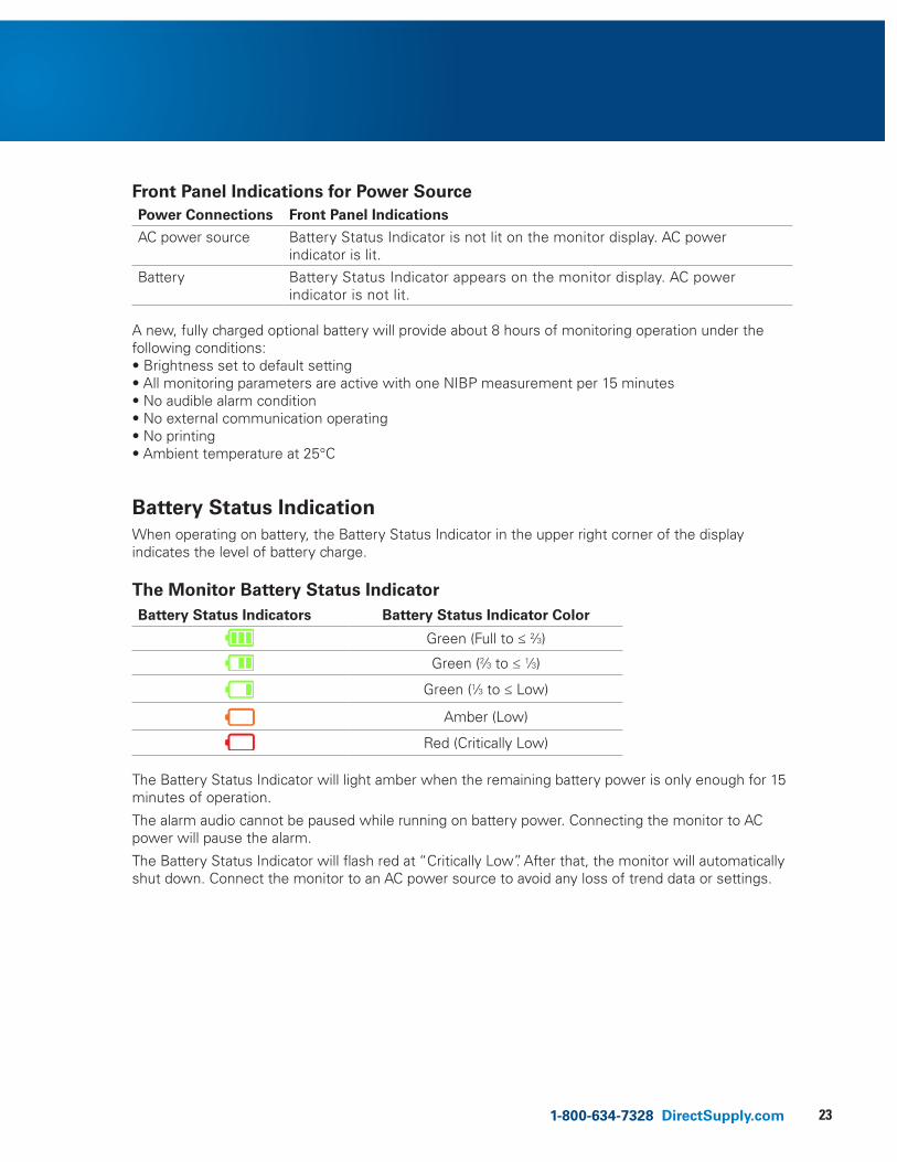
Front Panel Indications for Power SourcePower Connections Front Panel Indications
AC power source Battery Status Indicator is not lit on the monitor display. AC power indicator is lit.
Battery Battery Status Indicator appears on the monitor display. AC power indicator is not lit.
A new, fully charged optional battery will provide about 8 hours of monitoring operation under the following conditions: • Brightness set to default setting• All monitoring parameters are active with one NIBP measurement per 15 minutes • No audible alarm condition • No external communication operating • No printing • Ambient temperature at 25°C
Battery Status Indication
When operating on battery, the Battery Status Indicator in the upper right corner of the display indicates the level of battery charge.
The Monitor Battery Status IndicatorBattery Status Indicators Battery Status Indicator Color
Green (Full to ≤ 2⁄3)
Green (2⁄3 to ≤ 1⁄3)
Green (1⁄3 to ≤ Low)
Amber (Low)
Red (Critically Low) The Battery Status Indicator will light amber when the remaining battery power is only enough for 15 minutes of operation.
The alarm audio cannot be paused while running on battery power. Connecting the monitor to AC power will pause the alarm.
The Battery Status Indicator will flash red at “Critically Low”. After that, the monitor will automatically shut down. Connect the monitor to an AC power source to avoid any loss of trend data or settings.
24
Battery Operation (cont.)
Charging a Low Battery 1. Connect the monitor to an AC power source to charge a low or depleted battery (see the Setting
up the Monitor section).
2. Verify the Battery Charging Indicator is lit and amber.
Front Panel Indications for Battery StatusBattery status Battery Charging Indicator
Fully charged Green
Charging Amber
Not installed OFF
NOTE: Even if the monitor is turned off, the Battery Charging Indicator will light up while the battery is recharging.
NOTE: A full charge of a depleted battery takes over 12 hours.
NOTE: Always operate the monitor with the battery installed.
251-800-634-7328 DirectSupply.com
Using the Monitor
• WARNING: If the Power On Self-Test is not completed successfully, do not use the monitor.
• WARNING: Each time the monitor is used, check alarm limits to make sure that they are appropriate for the resident being monitored.
• WARNING: If different alarm presets are used for the same or similar equipment in any single area, e.g. an intensive care unit or cardiac operating room, a potential hazard can exist.
• WARNING: Keep residents under close surveillance when monitoring. It is possible, although unlikely, that radiated electromagnetic signals from sources external to the resident and the monitor can cause inaccurate measurement readings. Do not rely entirely on the monitor readings for resident assessment.
Overview of ModesThe monitor has nine modes of operation:
Normal Mode Normal Mode is the most basic mode when the monitor powered-on, it measures the NIBP, SpO2 and Temperature.
Service Mode Service Mode allows the user to set the system situation and system of the monitor.
Setting Mode Setting Mode allows the user to set the Target Pressure, Temperature Unit (Monitor Mode), Pulse Tone Volume and Alarm Volume.
Configuration Mode Configuration Mode allows the user to set the NIBP units, print mode, and the time and date.
Alarm Set Mode Alarm Set Mode allows the user to set the alarm limits (high, low) for NIBP, SpO2 and Temperature.
Auto/Interval Set Mode Auto/Interval Set Mode allows the user to select STAT mode or interval mode for NIBP measurements.
Review Mode Review Mode allows the user to check stored data on the monitor.
Firmware Mode Firmware Update Mode allows the user to update the firmware on the monitor.
Demo Mode The monitor is placed into Demo mode, displaying simulated values for NIBP, Temp, and SpO2.
Turning the Monitor On & OffBefore using the monitor, confirm that the monitor is working properly and is safe to use as described below.
• CAUTION: When power is turned on, the monitor automatically starts the Power-On Self-Test (POST), which tests the monitor circuitry, functions, and verifies checksum of the program. During Power-On Self-Test (POST), confirm that the monitor display turns on. If the monitor display does not function properly, do not use the monitor. Instead, contact Direct Supply.
NOTE: The POST pass tone sounds when the monitor completes the Power-On Self-Test (POST). This functions as an audible confirmation that the speaker is performing properly. If the speaker does not function, the alarm warning sounds cannot be heard.
NOTE: If a buzzer-like sound is heard, do not use the monitor. Instead, contact Direct Supply.
26
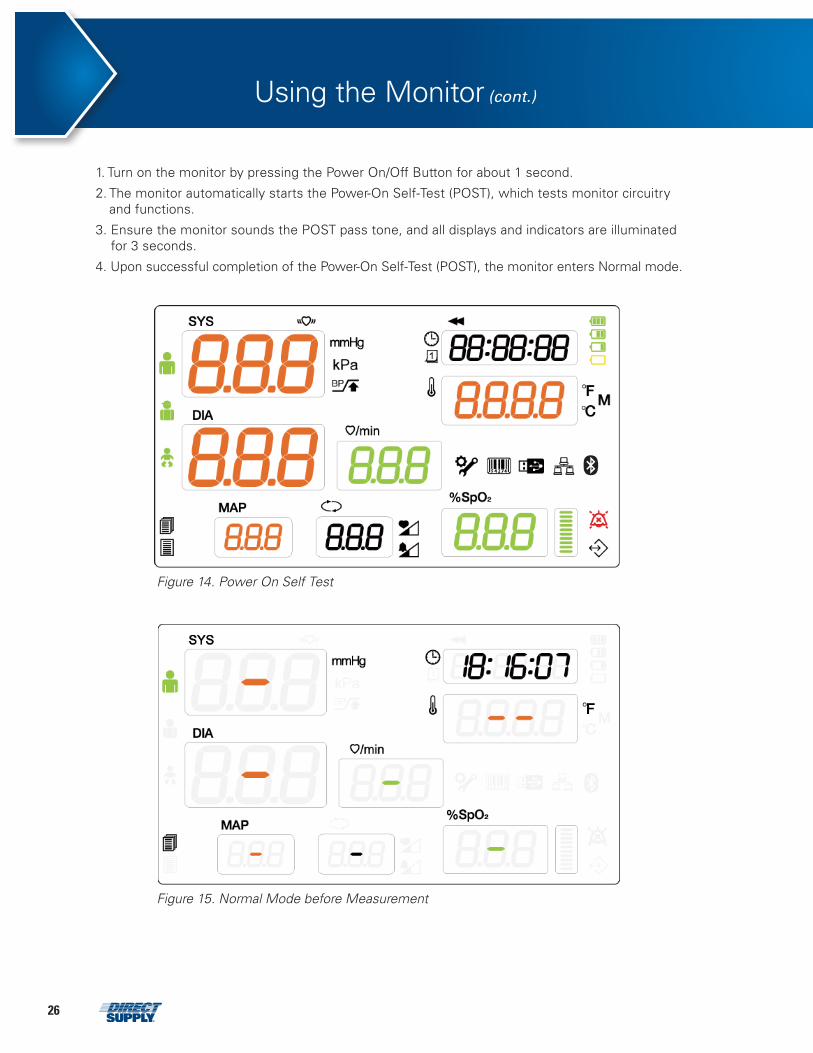
1. Turn on the monitor by pressing the Power On/Off Button for about 1 second.
2. The monitor automatically starts the Power-On Self-Test (POST), which tests monitor circuitry and functions.
3. Ensure the monitor sounds the POST pass tone, and all displays and indicators are illuminated for 3 seconds.
4. Upon successful completion of the Power-On Self-Test (POST), the monitor enters Normal mode.
attachments 5 – Figure 14. Power On Self Test
Figure 14. Power On Self Test
attachments 6 – Figure 15. Normal Mode before Measurement
Figure 15. Normal Mode before Measurement
Using the Monitor (cont.)
271-800-634-7328 DirectSupply.com
5. To turn off the monitor, press the Power On/Off Button for about 1.5 seconds.
NOTE: If the monitor doesn’t turn off normally, press the Power On/Off Button for 10 seconds.
NOTE: If the monitor detects an internal problem during Power-On Self-Test (POST), the monitor will display an error code. If an error code is displayed, contact Direct Supply.
NOTE: During the Power-On Self-Test (POST), verify the Battery Status Indicator (low) and Battery Status Indicator (critical low) is lit alternately at an interval of 0.5 seconds.
NOTE: During the Power-On Self-Test (POST), the monitor will not respond to any button presses. Wait until the Power-On Self-Test (POST) is complete (about 8 seconds) before using the monitor.
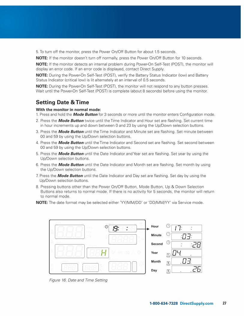
Setting Date & Time With the monitor in normal mode: 1. Press and hold the Mode Button for 3 seconds or more until the monitor enters Configuration mode.
2. Press the Mode Button twice until the Time Indicator and Hour set are flashing. Set current time in hour increments up and down between 0 and 23 by using the Up/Down selection buttons.
3. Press the Mode Button until the Time Indicator and Minute set are flashing. Set minute between 00 and 59 by using the Up/Down selection buttons.
4. Press the Mode Button until the Time Indicator and Second set are flashing. Set second between 00 and 59 by using the Up/Down selection buttons.
5. Press the Mode Button until the Date Indicator and Year set are flashing. Set year by using the Up/Down selection buttons.
6. Press the Mode Button until the Date Indicator and Month set are flashing. Set month by using the Up/Down selection buttons.
7. Press the Mode Button until the Date Indicator and Day set are flashing. Set day by using the Up/Down selection buttons.
8. Pressing buttons other than the Power On/Off Button, Mode Button, Up & Down Selection Buttons also returns to normal mode. If there is no activity for 5 seconds, the monitor will return to normal mode.
NOTE: The date format may be selected either ’YY/MM/DD’ or ’DD/MM/YY’ via Service mode.
Hour Minute Second Year Month Day
Figure 16. Date and Time Setting
28
Using the Monitor (cont.)
Setting Resident Type
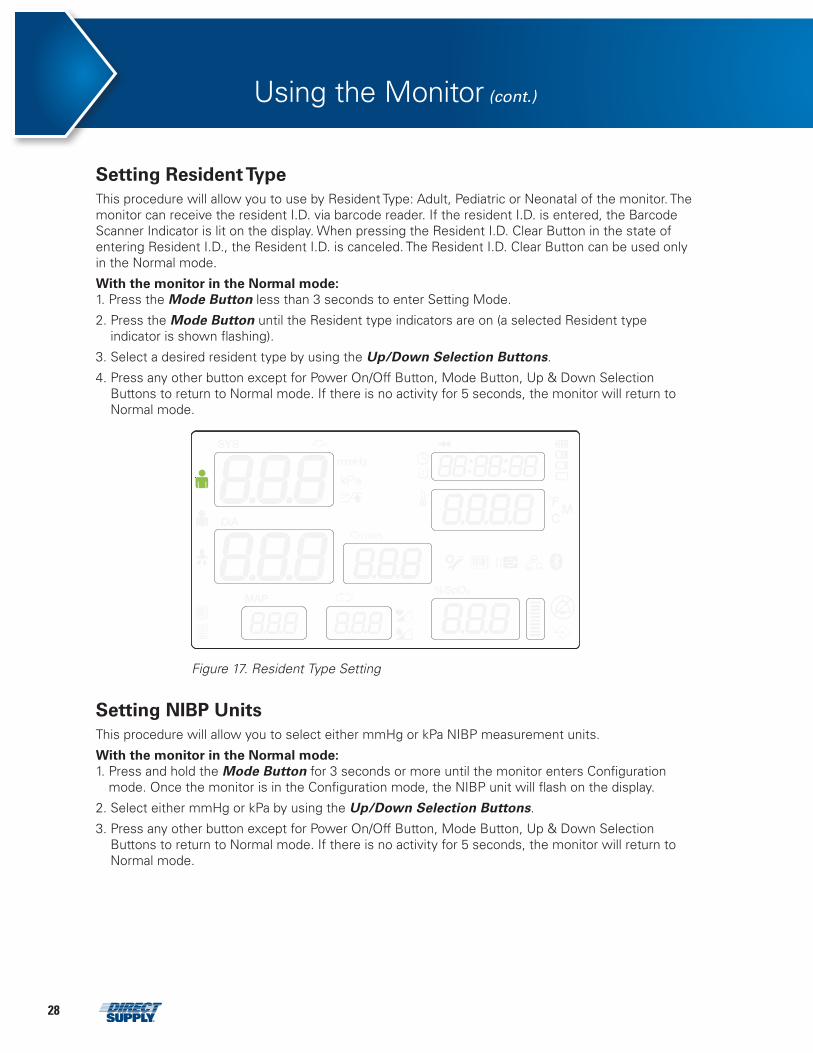
This procedure will allow you to use by Resident Type: Adult, Pediatric or Neonatal of the monitor. The monitor can receive the resident I.D. via barcode reader. If the resident I.D. is entered, the Barcode Scanner Indicator is lit on the display. When pressing the Resident I.D. Clear Button in the state of entering Resident I.D., the Resident I.D. is canceled. The Resident I.D. Clear Button can be used only in the Normal mode.
With the monitor in the Normal mode: 1. Press the Mode Button less than 3 seconds to enter Setting Mode.
2. Press the Mode Button until the Resident type indicators are on (a selected Resident type indicator is shown flashing).
3. Select a desired resident type by using the Up/Down Selection Buttons.
4. Press any other button except for Power On/Off Button, Mode Button, Up & Down Selection Buttons to return to Normal mode. If there is no activity for 5 seconds, the monitor will return to Normal mode.
Figure 17. Resident Type Setting
Setting NIBP Units
This procedure will allow you to select either mmHg or kPa NIBP measurement units.
With the monitor in the Normal mode: 1. Press and hold the Mode Button for 3 seconds or more until the monitor enters Configuration
mode. Once the monitor is in the Configuration mode, the NIBP unit will flash on the display.
2. Select either mmHg or kPa by using the Up/Down Selection Buttons.
3. Press any other button except for Power On/Off Button, Mode Button, Up & Down Selection Buttons to return to Normal mode. If there is no activity for 5 seconds, the monitor will return to Normal mode.
291-800-634-7328 DirectSupply.com
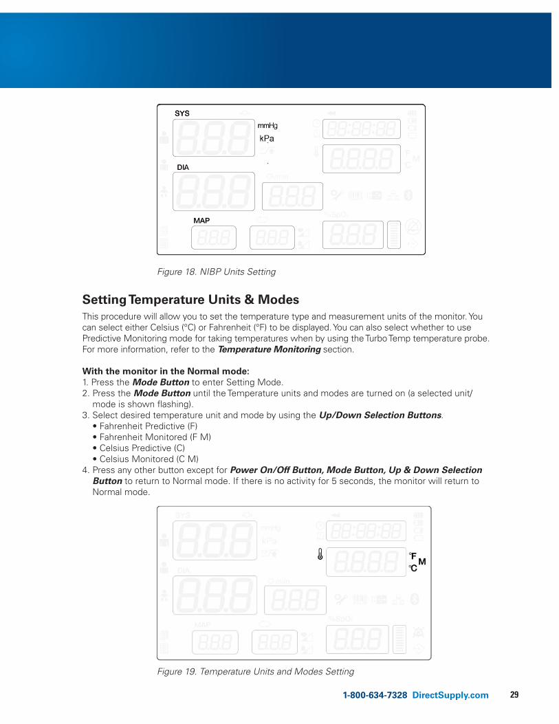
Setting Temperature Units & Modes
This procedure will allow you to set the temperature type and measurement units of the monitor. You can select either Celsius (°C) or Fahrenheit (°F) to be displayed. You can also select whether to use Predictive Monitoring mode for taking temperatures when by using the Turbo Temp temperature probe. For more information, refer to the Temperature Monitoring section.
With the monitor in the Normal mode: 1. Press the Mode Button to enter Setting Mode. 2. Press the Mode Button until the Temperature units and modes are turned on (a selected unit/
mode is shown flashing). 3. Select desired temperature unit and mode by using the Up/Down Selection Buttons.
• Fahrenheit Predictive (F) • Fahrenheit Monitored (F M) • Celsius Predictive (C) • Celsius Monitored (C M)
4. Press any other button except for Power On/Off Button, Mode Button, Up & Down Selection Button to return to Normal mode. If there is no activity for 5 seconds, the monitor will return to Normal mode.
attachments 9 – Figure 18. NIBP Units Setting
Figure 18. NIBP Units Setting
attachments 10 – Figure 19. Temperature Units and Modes Setting
Figure 19. Temperature Units and Modes Setting
30
Using the Monitor (cont.)
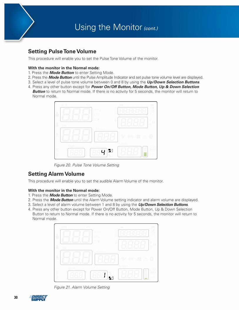
Setting Pulse Tone Volume This procedure will enable you to set the Pulse Tone Volume of the monitor.
With the monitor in the Normal mode: 1. Press the Mode Button to enter Setting Mode. 2. Press the Mode Button until the Pulse Amplitude Indicator and set pulse tone volume level are displayed. 3. Select a level of pulse tone volume between 0 and 8 by using the Up/Down Selection Buttons. 4. Press any other button except for Power On/Off Button, Mode Button, Up & Down Selection
Button to return to Normal mode. If there is no activity for 5 seconds, the monitor will return to Normal mode.
attachments 11 – Figure 20. Pulse Tone Volume Setting
Figure 20. Pulse Tone Volume Setting
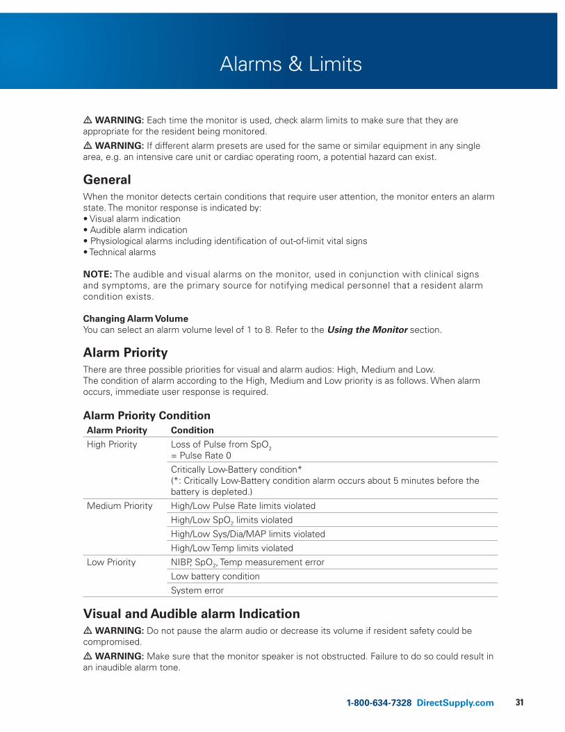
Setting Alarm Volume This procedure will enable you to set the audible Alarm Volume of the monitor.
With the monitor in the Normal mode: 1. Press the Mode Button to enter Setting Mode. 2. Press the Mode Button until the Alarm Volume setting indicator and alarm volume are displayed. 3. Select a level of alarm volume between 1 and 8 by using the Up/Down Selection Buttons. 4. Press any other button except for Power On/Off Button, Mode Button, Up & Down Selection
Button to return to Normal mode. If there is no activity for 5 seconds, the monitor will return to Normal mode.
attachments 12 – Figure 21. Alarm Volume Setting
Figure 21. Alarm Volume Setting
311-800-634-7328 DirectSupply.com
Alarms & Limits
• WARNING: Each time the monitor is used, check alarm limits to make sure that they are appropriate for the resident being monitored.
• WARNING: If different alarm presets are used for the same or similar equipment in any single area, e.g. an intensive care unit or cardiac operating room, a potential hazard can exist.
General When the monitor detects certain conditions that require user attention, the monitor enters an alarm state. The monitor response is indicated by: • Visual alarm indication • Audible alarm indication • Physiological alarms including identification of out-of-limit vital signs • Technical alarms
NOTE: The audible and visual alarms on the monitor, used in conjunction with clinical signs and symptoms, are the primary source for notifying medical personnel that a resident alarm condition exists.
Changing Alarm Volume You can select an alarm volume level of 1 to 8. Refer to the Using the Monitor section.
Alarm Priority There are three possible priorities for visual and alarm audios: High, Medium and Low. The condition of alarm according to the High, Medium and Low priority is as follows. When alarm occurs, immediate user response is required.
Alarm Priority ConditionAlarm Priority Condition
High Priority Loss of Pulse from SpO2 = Pulse Rate 0
Critically Low-Battery condition*(*: Critically Low-Battery condition alarm occurs about 5 minutes before the battery is depleted.)
Medium Priority High/Low Pulse Rate limits violated
High/Low SpO2 limits violated
High/Low Sys/Dia/MAP limits violated
High/Low Temp limits violated
Low Priority NIBP, SpO2, Temp measurement error
Low battery condition
System error Visual and Audible alarm Indication• WARNING: Do not pause the alarm audio or decrease its volume if resident safety could be compromised.
• WARNING: Make sure that the monitor speaker is not obstructed. Failure to do so could result in an inaudible alarm tone.
32
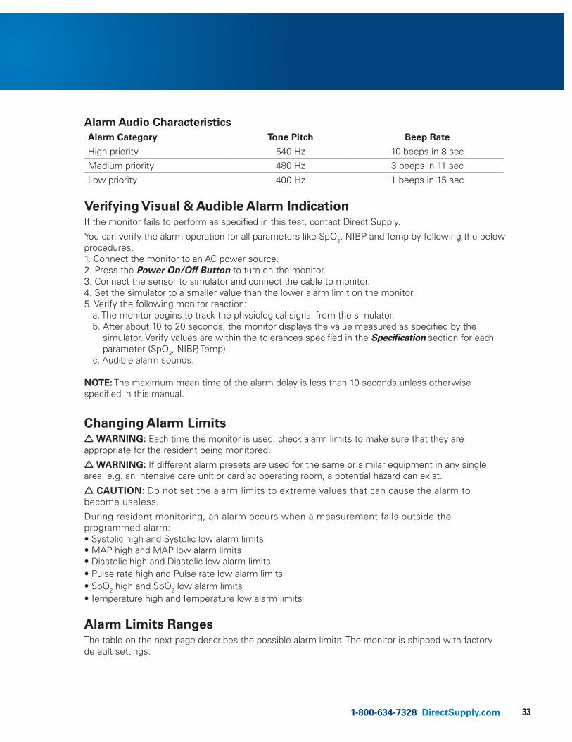
Alarm IndicationPhysiological Alarm
Condition Display Sound
Out of NIBP limit SYS, DIA, MAP, LED lit, according to the situation
Medium Priority Alarm Sound
Out of SpO2 limit SpO2 LED lit
Out of Temperature limit
Temperature LED lit
Out of Pulse Rate limit
PR LED lit
Loss of Pulse SpO2 LED lit High Priority Alarm Sound
Technical Alarm
Condition Display Sound
NIBP Error Displays the Error Code on SYS LED Low Priority Alarm Sound
SpO2 Error Displays the Error Code on SpO2 LED
Temperature Error Displays the Error Code on Temperature LED
NIBP measurement completion
Displays the SYS, DIA, MAP, PR Data Completion Sound
SpO2 Pulse Rate Displays the PR Data Pulse beep sound
Temperature spot measurement completion
Displays the Temperature Data Completion Sound
Temperature Probe Insert/Remove
None Temperature Probe Insert/Remove sound
System Condition Alarm
Condition Display Sound
POST Pass None POST Pass Sound
Change Power State (AC or Battery)
Power State LED Change Power Sound
Low Battery Power State LED Low : Low Priority Alarm Sound
Critical Low : High Priority Alarm Sound
Key Press None Key Press Sound (Valid/Invalid)
System Error, RTC Error, Sub CPU Error, Printer error
Displays the Error Code on SYS LED Low Priority Alarm Sound
Module communication error
NIBP – NIBP SYS Print – NIBP SYS
SpO2- SpO2Temp - Temp
Low Priority Alarm Sound
Alarms & Limits (cont.)
331-800-634-7328 DirectSupply.com
Alarm Audio CharacteristicsAlarm Category Tone Pitch Beep Rate
High priority 540 Hz 10 beeps in 8 sec
Medium priority 480 Hz 3 beeps in 11 sec
Low priority 400 Hz 1 beeps in 15 sec
Verifying Visual & Audible Alarm Indication If the monitor fails to perform as specified in this test, contact Direct Supply.
You can verify the alarm operation for all parameters like SpO2, NIBP and Temp by following the below procedures. 1. Connect the monitor to an AC power source. 2. Press the Power On/Off Button to turn on the monitor. 3. Connect the sensor to simulator and connect the cable to monitor. 4. Set the simulator to a smaller value than the lower alarm limit on the monitor. 5. Verify the following monitor reaction: a. The monitor begins to track the physiological signal from the simulator. b. After about 10 to 20 seconds, the monitor displays the value measured as specified by the
simulator. Verify values are within the tolerances specified in the Specification section for each parameter (SpO2, NIBP, Temp).
c. Audible alarm sounds.
NOTE: The maximum mean time of the alarm delay is less than 10 seconds unless otherwise specified in this manual.
Changing Alarm Limits• WARNING: Each time the monitor is used, check alarm limits to make sure that they are appropriate for the resident being monitored.
• WARNING: If different alarm presets are used for the same or similar equipment in any single area, e.g. an intensive care unit or cardiac operating room, a potential hazard can exist.
• CAUTION: Do not set the alarm limits to extreme values that can cause the alarm to become useless.
During resident monitoring, an alarm occurs when a measurement falls outside the programmed alarm: • Systolic high and Systolic low alarm limits • MAP high and MAP low alarm limits• Diastolic high and Diastolic low alarm limits • Pulse rate high and Pulse rate low alarm limits • SpO2 high and SpO2 low alarm limits • Temperature high and Temperature low alarm limits
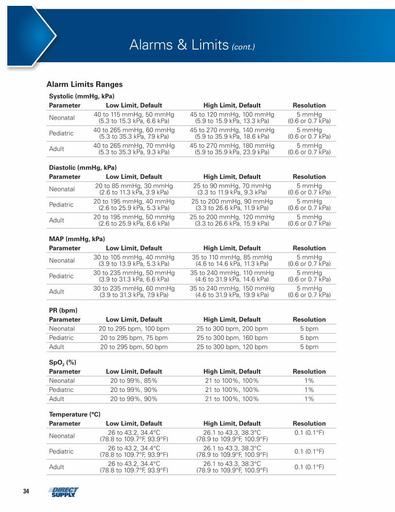
Alarm Limits Ranges The table on the next page describes the possible alarm limits. The monitor is shipped with factory default settings.
34
Alarms & Limits (cont.)
Alarm Limits RangesSystolic (mmHg, kPa) Parameter Low Limit, Default High Limit, Default Resolution
Neonatal 40 to 115 mmHg, 50 mmHg (5.3 to 15.3 kPa, 6.6 kPa)
45 to 120 mmHg, 100 mmHg(5.9 to 15.9 kPa, 13.3 kPa)
5 mmHg(0.6 or 0.7 kPa)
Pediatric 40 to 265 mmHg, 60 mmHg (5.3 to 35.3 kPa, 7.9 kPa)
45 to 270 mmHg, 140 mmHg (5.9 to 35.9 kPa, 18.6 kPa)
5 mmHg(0.6 or 0.7 kPa)
Adult 40 to 265 mmHg, 70 mmHg (5.3 to 35.3 kPa, 9.3 kPa)
45 to 270 mmHg, 180 mmHg(5.9 to 35.9 kPa, 23.9 kPa)
5 mmHg(0.6 or 0.7 kPa)
Diastolic (mmHg, kPa) Parameter Low Limit, Default High Limit, Default Resolution
Neonatal 20 to 85 mmHg, 30 mmHg (2.6 to 11.3 kPa, 3.9 kPa)
25 to 90 mmHg, 70 mmHg(3.3 to 11.9 kPa, 9.3 kPa)
5 mmHg(0.6 or 0.7 kPa)
Pediatric 20 to 195 mmHg, 40 mmHg (2.6 to 25.9 kPa, 5.3 kPa)
25 to 200 mmHg, 90 mmHg(3.3 to 26.6 kPa, 11.9 kPa)
5 mmHg (0.6 or 0.7 kPa)
Adult 20 to 195 mmHg, 50 mmHg (2.6 to 25.9 kPa, 6.6 kPa)
25 to 200 mmHg, 120 mmHg(3.3 to 26.6 kPa, 15.9 kPa)
5 mmHg(0.6 or 0.7 kPa)
MAP (mmHg, kPa)Parameter Low Limit, Default High Limit, Default Resolution
Neonatal 30 to 105 mmHg, 40 mmHg(3.9 to 13.9 kPa, 5.3 kPa)
35 to 110 mmHg, 85 mmHg(4.6 to 14.6 kPa, 11.3 kPa)
5 mmHg(0.6 or 0.7 kPa)
Pediatric 30 to 235 mmHg, 50 mmHg(3.9 to 31.3 kPa, 6.6 kPa)
35 to 240 mmHg, 110 mmHg(4.6 to 31.9 kPa, 14.6 kPa)
5 mmHg(0.6 or 0.7 kPa)
Adult 30 to 235 mmHg, 60 mmHg(3.9 to 31.3 kPa, 7.9 kPa)
35 to 240 mmHg, 150 mmHg(4.6 to 31.9 kPa, 19.9 kPa)
5 mmHg(0.6 or 0.7 kPa)
PR (bpm) Parameter Low Limit, Default High Limit, Default Resolution Neonatal 20 to 295 bpm, 100 bpm 25 to 300 bpm, 200 bpm 5 bpm Pediatric 20 to 295 bpm, 75 bpm 25 to 300 bpm, 160 bpm 5 bpm Adult 20 to 295 bpm, 50 bpm 25 to 300 bpm, 120 bpm 5 bpm
SpO2 (%) Parameter Low Limit, Default High Limit, Default Resolution Neonatal 20 to 99%, 85% 21 to 100%, 100% 1% Pediatric 20 to 99%, 90% 21 to 100%, 100% 1% Adult 20 to 99%, 90% 21 to 100%, 100% 1%
Temperature (°C) Parameter Low Limit, Default High Limit, Default Resolution
Neonatal 26 to 43.2, 34.4°C (78.8 to 109.7°F, 93.9°F)
26.1 to 43.3, 38.3°C(78.9 to 109.9°F, 100.9°F)
0.1 (0.1°F)
Pediatric 26 to 43.2, 34.4°C (78.8 to 109.7°F, 93.9°F)
26.1 to 43.3, 38.3°C(78.9 to 109.9°F, 100.9°F) 0.1 (0.1°F)
Adult 26 to 43.2, 34.4°C (78.8 to 109.7°F, 93.9°F)
26.1 to 43.3, 38.3°C (78.9 to 109.9°F, 100.9°F) 0.1 (0.1°F)
351-800-634-7328 DirectSupply.com
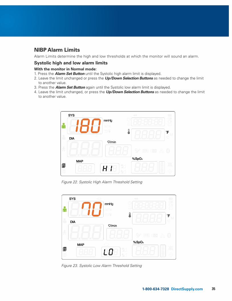
NIBP Alarm Limits Alarm Limits determine the high and low thresholds at which the monitor will sound an alarm.
Systolic high and low alarm limits With the monitor in Normal mode: 1. Press the Alarm Set Button until the Systolic high alarm limit is displayed. 2. Leave the limit unchanged or press the Up/Down Selection Buttons as needed to change the limit
to another value. 3. Press the Alarm Set Button again until the Systolic low alarm limit is displayed. 4. Leave the limit unchanged, or press the Up/Down Selection Buttons as needed to change the limit
to another value.
attachments 13 – Figure 22. Systolic High Alarm Limit Setting
attachments 14 – Figure 23. Systolic Low Alarm Limit Setting
Figure 22. Systolic High Alarm Threshold Setting
Figure 23. Systolic Low Alarm Threshold Setting
36
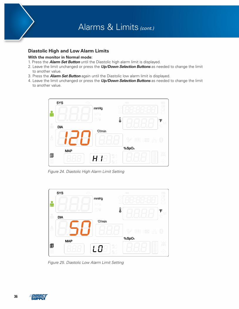
Diastolic High and Low Alarm Limits
With the monitor in Normal mode: 1. Press the Alarm Set Button until the Diastolic high alarm limit is displayed. 2. Leave the limit unchanged or press the Up/Down Selection Buttons as needed to change the limit
to another value. 3. Press the Alarm Set Button again until the Diastolic low alarm limit is displayed. 4. Leave the limit unchanged or press the Up/Down Selection Buttons as needed to change the limit
to another value.
Alarms & Limits (cont.)
attachments 15 – Figure 24. Iastolic High Alarm Limit Setting
Figure 24. Diastolic High Alarm Limit Setting
attachments 16 – Figure 25. Diastolic Low Alarm Limit Setting
Figure 25. Diastolic Low Alarm Limit Setting
371-800-634-7328 DirectSupply.com
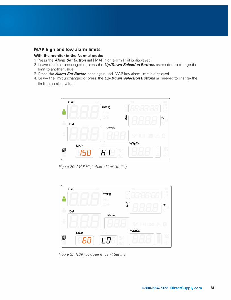
MAP high and low alarm limitsWith the monitor in the Normal mode:1. Press the Alarm Set Button until MAP high alarm limit is displayed.2. Leave the limit unchanged or press the Up/Down Selection Buttons as needed to change the
limit to another value.3. Press the Alarm Set Button once again until MAP low alarm limit is displayed.4. Leave the limit unchanged or press the Up/Down Selection Buttons as needed to change the
limit to another value.
attachments 17 – Figure 26. MAP High Alarm Limit Setting
attachments 18 – Figure 27. MAP Low Alarm Limit Setting
Figure 26. MAP High Alarm Limit Setting
Figure 27. MAP Low Alarm Limit Setting
38
Alarms & Limits (cont.)
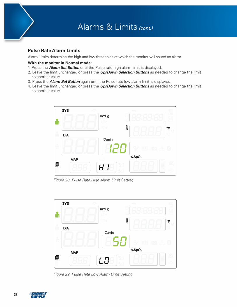
Pulse Rate Alarm Limits
Alarm Limits determine the high and low thresholds at which the monitor will sound an alarm.
With the monitor in Normal mode: 1. Press the Alarm Set Button until the Pulse rate high alarm limit is displayed. 2. Leave the limit unchanged or press the Up/Down Selection Buttons as needed to change the limit
to another value. 3. Press the Alarm Set Button again until the Pulse rate low alarm limit is displayed. 4. Leave the limit unchanged or press the Up/Down Selection Buttons as needed to change the limit
to another value.
attachments 20 – Figure 29. Pulse Rate Low Alarm Limit Setting
attachments 19 – Figure 28. Pulse Rate High Alarm Limit Setting
Figure 28. Pulse Rate High Alarm Limit Setting
Figure 29. Pulse Rate Low Alarm Limit Setting
391-800-634-7328 DirectSupply.com
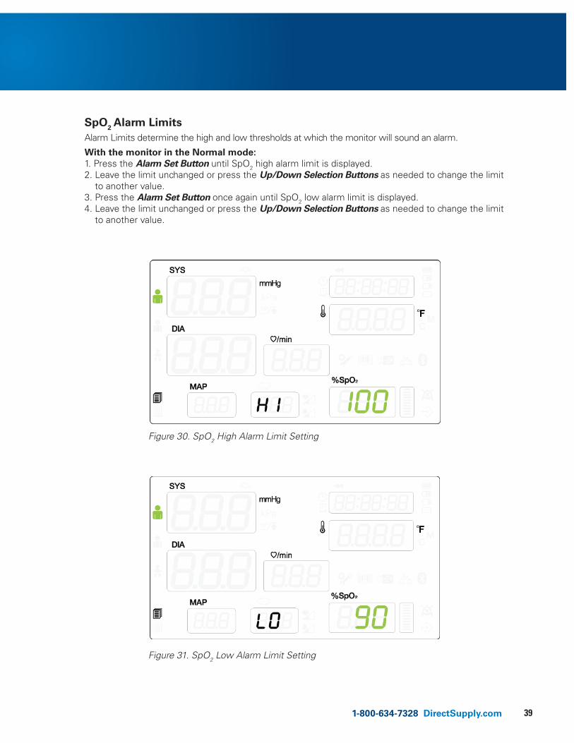
SpO2 Alarm Limits
Alarm Limits determine the high and low thresholds at which the monitor will sound an alarm.
With the monitor in the Normal mode: 1. Press the Alarm Set Button until SpO2 high alarm limit is displayed. 2. Leave the limit unchanged or press the Up/Down Selection Buttons as needed to change the limit
to another value. 3. Press the Alarm Set Button once again until SpO2 low alarm limit is displayed. 4. Leave the limit unchanged or press the Up/Down Selection Buttons as needed to change the limit
to another value.
attachments 22 – Figure 31. SpO2 Low Alarm Limit Setting
attachments 21 – Figure 30. SpO2 High Alarm Limit Setting
Figure 30. SpO2 High Alarm Limit Setting
Figure 31. SpO2 Low Alarm Limit Setting
40
Alarms & Limits (cont.)
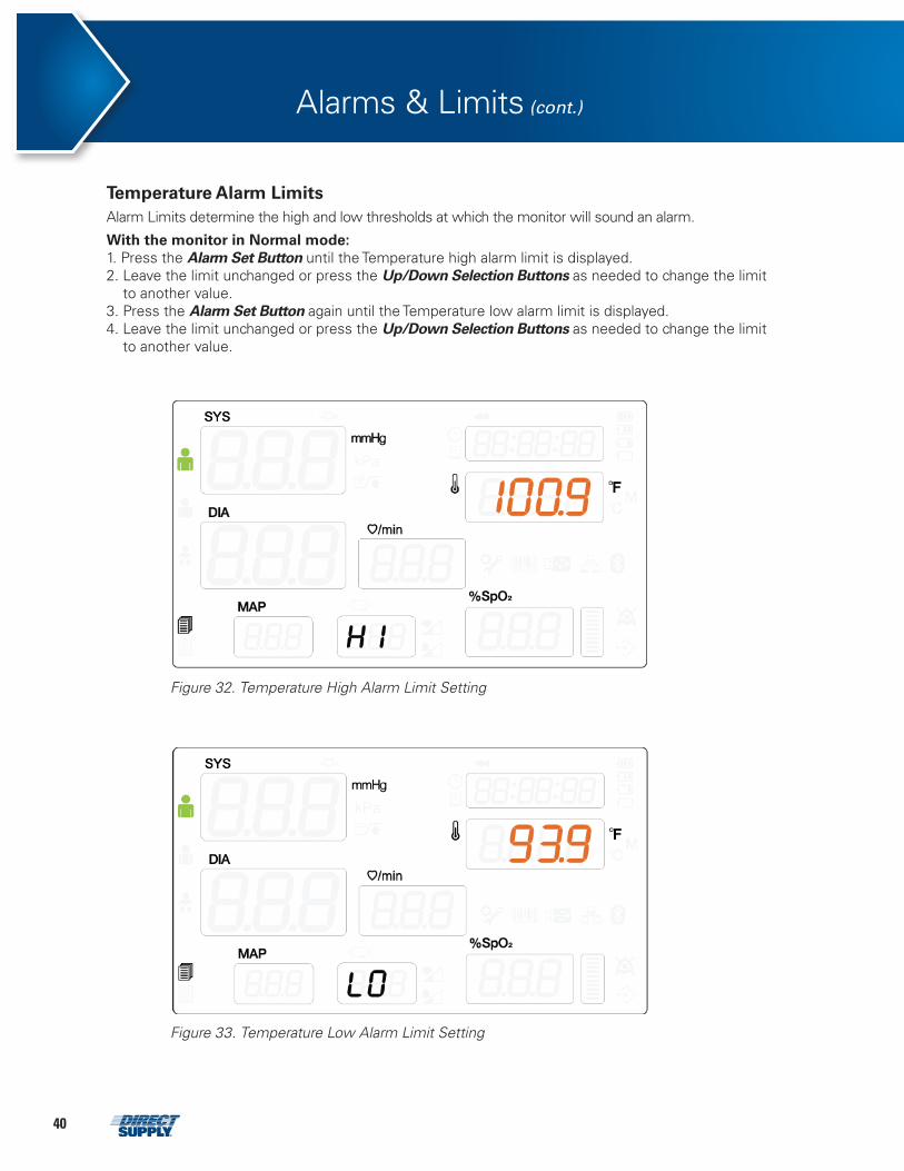
Temperature Alarm Limits Alarm Limits determine the high and low thresholds at which the monitor will sound an alarm.
With the monitor in Normal mode: 1. Press the Alarm Set Button until the Temperature high alarm limit is displayed. 2. Leave the limit unchanged or press the Up/Down Selection Buttons as needed to change the limit
to another value. 3. Press the Alarm Set Button again until the Temperature low alarm limit is displayed. 4. Leave the limit unchanged or press the Up/Down Selection Buttons as needed to change the limit
to another value.
attachments 23 – Figure 32. Temperature High Alarm Limit Setting
attachments 24 – Figure 33. Temperature Low Alarm Limit Setting
Figure 32. Temperature High Alarm Limit Setting
Figure 33. Temperature Low Alarm Limit Setting
411-800-634-7328 DirectSupply.com
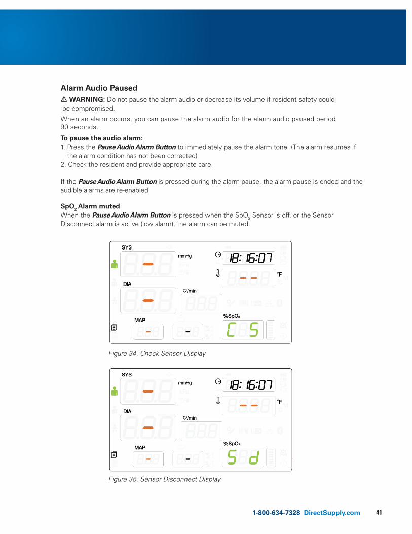
Alarm Audio Paused
• WARNING: Do not pause the alarm audio or decrease its volume if resident safety could be compromised.
When an alarm occurs, you can pause the alarm audio for the alarm audio paused period 90 seconds.
To pause the audio alarm: 1. Press the Pause Audio Alarm Button to immediately pause the alarm tone. (The alarm resumes if
the alarm condition has not been corrected) 2. Check the resident and provide appropriate care.
If the Pause Audio Alarm Button is pressed during the alarm pause, the alarm pause is ended and the audible alarms are re-enabled.
SpO2 Alarm muted When the Pause Audio Alarm Button is pressed when the SpO2 Sensor is off, or the Sensor Disconnect alarm is active (low alarm), the alarm can be muted.
attachments 25 – Figure 34. Check Sensor Display
attachments 26 – Figure 35. Sensor Disconnect Display
Figure 34. Check Sensor Display
Figure 35. Sensor Disconnect Display
42
• WARNING: For best product performance and measurement accuracy, use only accessories intended for use with this monitor. Use accessories according to the manufacturer’s directions for use and your facility’s standards.
• WARNING: Inaccurate measurements may be caused by incorrect cuff application or use. This can include placing the cuff too loosely on the resident using the incorrect cuff size, or not placing the cuff at the same level as the heart, using a leaky cuff or hose, or excessive resident motion.
• WARNING: In some cases, rapid, prolonged cycling of an oscillometric, noninvasive blood pressure monitor cuff has been associated with any or all of the following: ischemia, purpura, or neuropathy. Periodically observe the resident’s limb to make sure that the circulation is not impaired for a prolonged period of time. Also make sure the cuff is placed according to directions in this manual and the cuff directions for use.
• WARNING: Do not place the cuff, the catheter or SpO2 sensor on an extremity being used for intravenous infusion or any area where circulation is compromised or has the potential to be compromised.
• WARNING: As with all automatically inflatable blood pressure devices, continual cuff measurements can cause injury to the resident being monitored. Weigh the advantages of frequent measurement and/or use of STAT mode against the risk of injury.
• WARNING: Ensure the resident is quiet with minimal movement during NIBP readings; minimize the resident’s shivering.
• WARNING: Never place the cuff on an extremity being used for intravenous infusion or any area where circulation is compromised or has the potential to be compromised. Never fit NIBP system with Luer Lock adapters.
• WARNING: Never use an adult monitor setting or cuff for an NIBP measurement on a neonatal resident. Adult inflation limits can be excessive for neonatal residents, even if a neonatal cuff is used.
• WARNING: Too frequent of measurements can cause injury to the resident due to blood flow interference.
• WARNING: The cuff should not be applied over a wound as this can cause further injury.
• WARNING: The cuff should not be placed on the arm on the side of a mastectomy. In the case of a double mastectomy use the side of the least dominant arm.
• WARNING: Pressurization of the cuff can temporarily cause loss of function of simultaneously used monitoring equipment on the same limb.
• WARNING: Do not attach the cuff to a limb being used for IV infusions or any other intravascular access, therapy or an arterio-venous (A-V) shunt. The cuff inflation can temporarily block blood flow, potentially causing harm to the resident.
• WARNING: Any blood pressure reading can be affected by the measurement site, the position of the resident, exercise, or the resident’s physiologic condition. Environmental or operational factors which can affect the performance of the monitor and/or its blood pressure reading are common arrhythmias such as atrial or ventricular premature beats or atrial fibrillation, arterial sclerosis, poor perfusion, diabetes, age, pregnancy, pre-eclampsia, renal diseases, resident motion, trembling and shivering.
• CAUTION: In automatic mode, the monitor displays results of the last blood pressure measurement until another measurement starts. If a resident’s condition changes during the time interval between measurements, the monitor will not detect the change or indicate an alarm condition.
• CAUTION: Any excessive resident motion may cause inaccurate measurements of non-invasive blood pressure. Minimize motion to improve blood pressure measurements.
NIBP Monitoring
431-800-634-7328 DirectSupply.com
• CAUTION: Do not apply the blood pressure cuff to the same extremity as the one to which the SpO2 sensor is attached. Cuff inflation can disrupt SpO2 monitoring and lead to nuisance alarms.
• CAUTION: Make sure that heavy objects are not placed on the cuff hose. Avoid crimping or undue bending, twisting, or entanglement of the hose.
• CAUTION: A compressed or kinked connection hose may cause continuous cuff pressure resulting in blood flow interference and potentially harmful injury to the resident.
NOTE: Blood pressure measurements can be affected by the position of the resident, the resident’s physiological condition and other factors.
NOTE: Blood pressure measurements determined with the monitor are equivalent to those obtained by a trained observer using the cuff/stethoscope auscultatory method, within the limits prescribed by the American National Standard for manual, electronic and automated sphygmomanometers.
NOTE: 5 minutes should elapse before the first reading is taken.
NOTE: The user should check that the monitor is functioning while measurements are being made and check display periodically.
NOTE: Check the cuff/hose connection and do not use a damaged cuff/hose. Follow the manufacturer’s directions for use.
General The monitor performs Noninvasive Blood Pressure measurements using the oscillometric measuring technique. A motorized pump inflates the cuff to initially blocking the flow of blood in the extremity. Then, under monitor control, the pressure in the cuff is gradually reduced, while a pressure transducer detects air pressure and transmits a signal to the NIBP circuitry.
When the cuff pressure is still above systolic pressure, small pulses or oscillations in the cuff pressure begin to be sensed by the transducer. As the cuff continues to deflate, oscillation amplitude increases to a maximum and then decreases. When maximum oscillation amplitude occurs, the cuff pressure at that time is measured as mean arterial pressure (MAP). The systolic and diastolic pressures are calculated based on analysis of the oscillation amplitude profile.
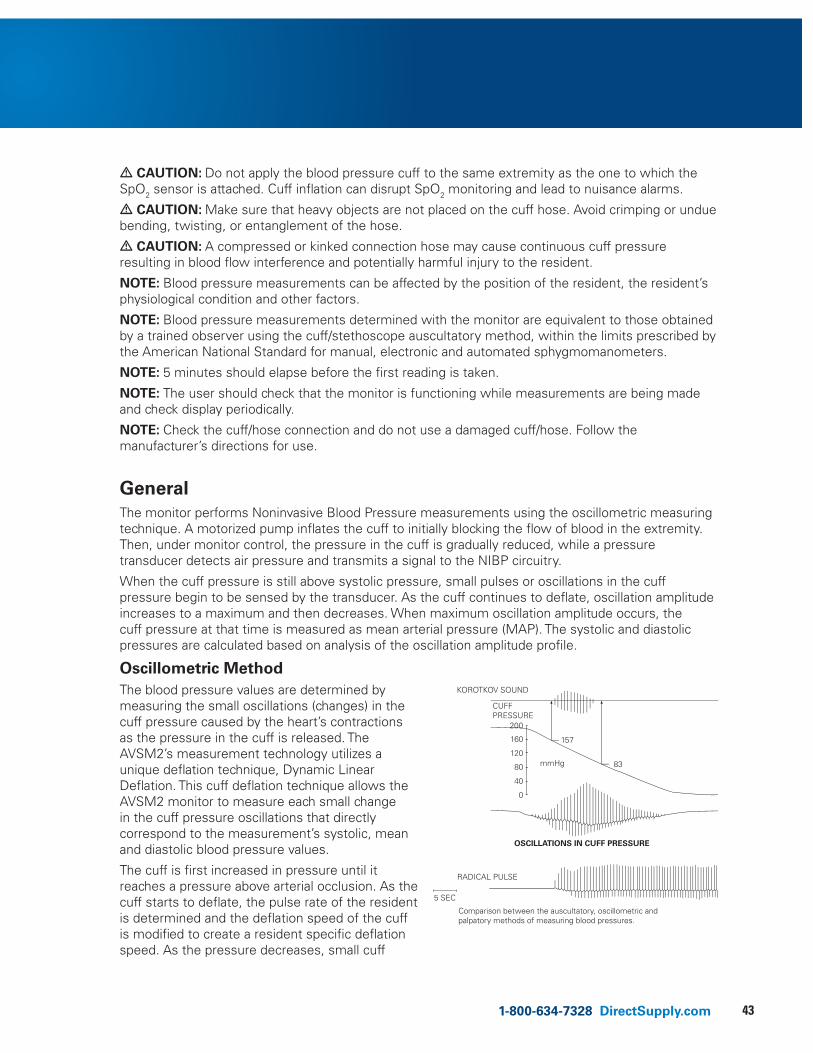
Oscillometric Method
The blood pressure values are determined by measuring the small oscillations (changes) in the cuff pressure caused by the heart’s contractions as the pressure in the cuff is released. The AVSM2’s measurement technology utilizes a unique deflation technique, Dynamic Linear Deflation. This cuff deflation technique allows the AVSM2 monitor to measure each small change in the cuff pressure oscillations that directly correspond to the measurement’s systolic, mean and diastolic blood pressure values.
The cuff is first increased in pressure until it reaches a pressure above arterial occlusion. As the cuff starts to deflate, the pulse rate of the resident is determined and the deflation speed of the cuff is modified to create a resident specific deflation speed. As the pressure decreases, small cuff
Comparison between the auscultatory, oscillometric and palpatory methods of measuring blood pressures.
RADICAL PULSE
5 SEC
OSCILLATIONS IN CUFF PRESSURE
CUFFPRESSURE
KOROTKOV SOUND
200
160
120
80
40
0
mmHg
157
83
44
NIBP Monitoring (cont.)
pressure oscillations are recorded that correspond to the applied pressure of the blood under the cuff as the heart contracts. These oscillations increase in strength as the cuff pressure approaches the systolic blood pressure value. A sudden increase in oscillation amplitude indicates that the resident’s systolic blood pressure is now able to push blood completely through beneath the cuff. The oscillation amplitude continues to increase as the pressure in the cuff is decreases until the mean blood pressure value is reached. The oscillation strength then starts to diminish and finally drop off as the diastolic blood pressure value is reached.
The oscillometric method does not determine an instantaneous blood pressure reading like the auscultatory method employing a microphone-type auto blood pressure monitor but, as described above, determines blood pressure from an uninterrupted changing curve, which means that the oscillometric method is not easily affected by external noise.
Setup ConnectionsWhen performing NIBP measurements, including hypertension blood pressure measurements, it is important to follow the procedures below to ensure valid, accurate results.
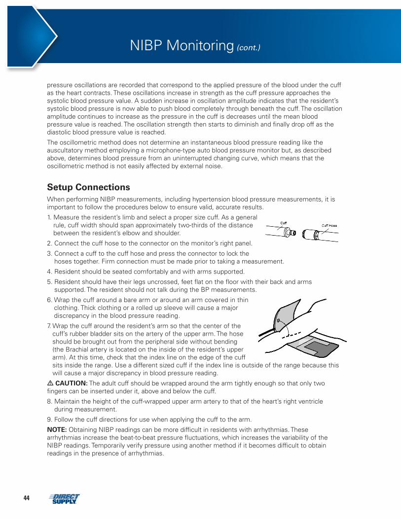
1. Measure the resident’s limb and select a proper size cuff. As a general rule, cuff width should span approximately two-thirds of the distance between the resident’s elbow and shoulder.
2. Connect the cuff hose to the connector on the monitor’s right panel.
3. Connect a cuff to the cuff hose and press the connector to lock the hoses together. Firm connection must be made prior to taking a measurement.
4. Resident should be seated comfortably and with arms supported.
5. Resident should have their legs uncrossed, feet flat on the floor with their back and arms supported. The resident should not talk during the BP measurements.
6. Wrap the cuff around a bare arm or around an arm covered in thin clothing. Thick clothing or a rolled up sleeve will cause a major discrepancy in the blood pressure reading.
7. Wrap the cuff around the resident’s arm so that the center of the cuff’s rubber bladder sits on the artery of the upper arm. The hose should be brought out from the peripheral side without bending (the Brachial artery is located on the inside of the resident’s upper arm). At this time, check that the index line on the edge of the cuff sits inside the range. Use a different sized cuff if the index line is outside of the range because this will cause a major discrepancy in blood pressure reading.
• CAUTION: The adult cuff should be wrapped around the arm tightly enough so that only two fingers can be inserted under it, above and below the cuff.
8. Maintain the height of the cuff-wrapped upper arm artery to that of the heart’s right ventricle during measurement.
9. Follow the cuff directions for use when applying the cuff to the arm.
NOTE: Obtaining NIBP readings can be more difficult in residents with arrhythmias. These arrhythmias increase the beat-to-beat pressure fluctuations, which increases the variability of the NIBP readings. Temporarily verify pressure using another method if it becomes difficult to obtain readings in the presence of arrhythmias.
451-800-634-7328 DirectSupply.com
Cuff SizeModel Number Arm Circumference (cm) Subject
CUF-KS-SA 16.0 to 24.0
AdultCUF-KS-A 22.0 to 32.0
CUF-KS-LA 31.0 to 45.0
CUF-KS-LL 41.0 to 50.0
NIBP Measurement Modes
Blood pressure measurements can be made in four modes:
• MANUAL mode: Single measurement of systolic/diastolic arterial pressure.
• Long Term Interval mode: Continuous measurement for set interval (above 2 minutes).
• Short Term Interval mode: Continuous measurement for set interval (1 minute).
• Short Term Auto (STAT) mode: As many measurements as possible within a 5-minute period. After measuring by STAT mode, the continuous measurement interval will be changed to 3 minutes.
Description of NIBP Menu Functions Setting Initial Inflation Pressure With the monitor in the Normal mode:
1. Press the Mode Button to the monitor enter Setting Mode.
2. Press the Mode Button twice until NIBP target inflation is displayed.
3. Change desired NIBP target inflation by using the Up/Down Selection Buttons.
4. Press any other button except for Power On/Off Button, Mode Button, Up & Down Selection Button to return to Normal mode. If there is no activity for 5 seconds, the monitor will return to Normal mode.
The numeric display in the lower right corner of the NIBP frame indicates the setting of the initial inflation pressure. The initial inflation pressure can be set from 120 to 260 mmHg for adult, 120 to 170 mmHg for pediatric, 80 to 140 mmHg for neonatal, in intervals of 10 or 20 mmHg. You may select an initial cuff inflation pressure. This is particularly important with children, since an initial cuff inflation pressure of factory default, 180 mmHg for adult, 140 mmHg for pediatric, 100 mmHg for neonatal may be uncomfortable and is typically higher than it needs to be.
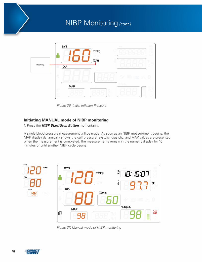
46
attachments 28 – Figure 37. Manual Mode of NIBP Monitoring
Initiating MANUAL mode of NIBP monitoring
1. Press the NIBP Start/Stop Button momentarily.
A single blood pressure measurement will be made. As soon as an NIBP measurement begins, the MAP display dynamically shows the cuff pressure. Systolic, diastolic, and MAP values are presented when the measurement is completed. The measurements remain in the numeric display for 10 minutes or until another NIBP cycle begins.
NIBP Monitoring (cont.)
attachments 27 – Figure 36. Initial Inflation Pressure
Figure 36. Initial Inflation Pressure
Figure 37. Manual mode of NIBP monitoring
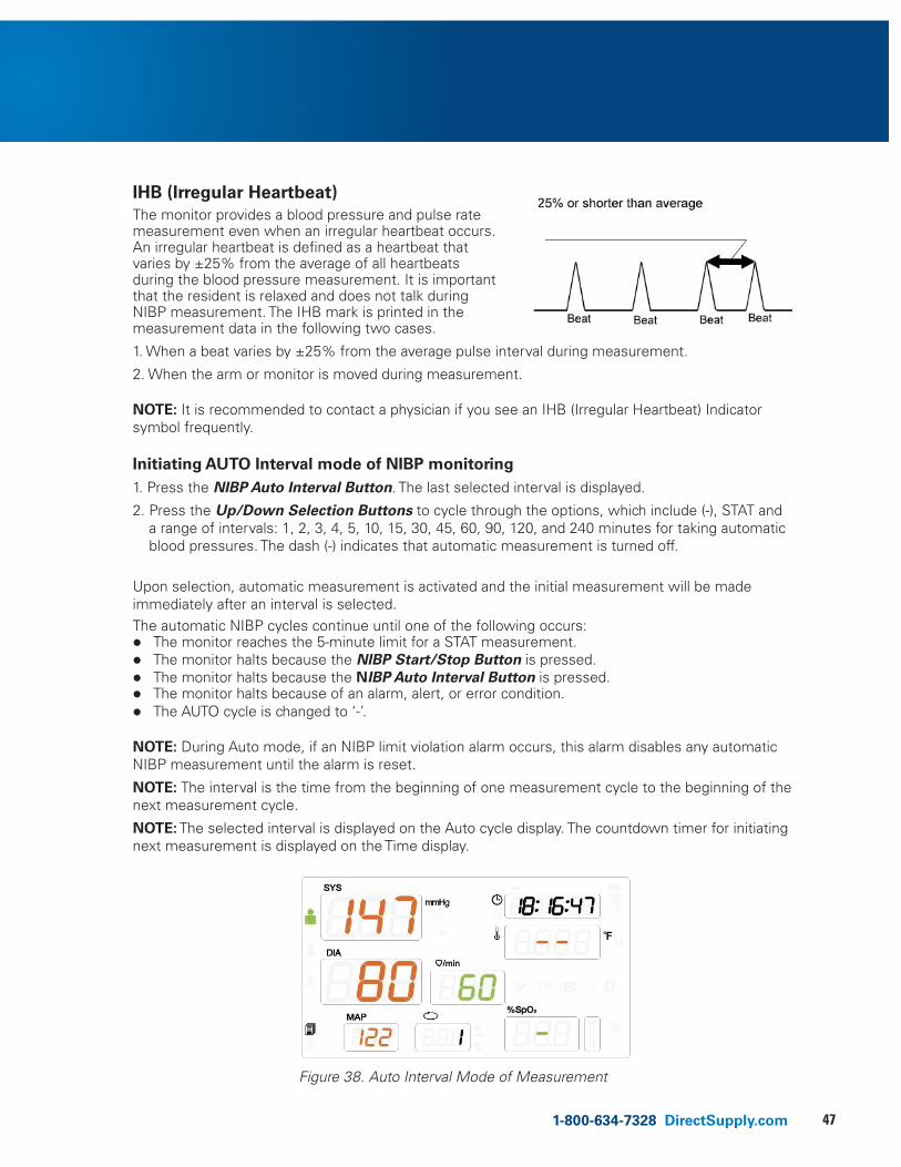
471-800-634-7328 DirectSupply.com
IHB (Irregular Heartbeat) The monitor provides a blood pressure and pulse rate measurement even when an irregular heartbeat occurs. An irregular heartbeat is defined as a heartbeat that varies by ±25% from the average of all heartbeats during the blood pressure measurement. It is important that the resident is relaxed and does not talk during NIBP measurement. The IHB mark is printed in the measurement data in the following two cases.
1. When a beat varies by ±25% from the average pulse interval during measurement.
2. When the arm or monitor is moved during measurement.
NOTE: It is recommended to contact a physician if you see an IHB (Irregular Heartbeat) Indicator symbol frequently.
Initiating AUTO Interval mode of NIBP monitoring 1. Press the NIBP Auto Interval Button. The last selected interval is displayed.
2. Press the Up/Down Selection Buttons to cycle through the options, which include (-), STAT and a range of intervals: 1, 2, 3, 4, 5, 10, 15, 30, 45, 60, 90, 120, and 240 minutes for taking automatic blood pressures. The dash (-) indicates that automatic measurement is turned off.
Upon selection, automatic measurement is activated and the initial measurement will be made immediately after an interval is selected. The automatic NIBP cycles continue until one of the following occurs: l The monitor reaches the 5-minute limit for a STAT measurement. l The monitor halts because the NIBP Start/Stop Button is pressed. l The monitor halts because the NIBP Auto Interval Button is pressed. l The monitor halts because of an alarm, alert, or error condition. l The AUTO cycle is changed to ‘-’.
NOTE: During Auto mode, if an NIBP limit violation alarm occurs, this alarm disables any automatic NIBP measurement until the alarm is reset.
NOTE: The interval is the time from the beginning of one measurement cycle to the beginning of the next measurement cycle.
NOTE: The selected interval is displayed on the Auto cycle display. The countdown timer for initiating next measurement is displayed on the Time display.
attachments 29 – Figure 38. Auto Interval Mode of Measurement
Figure 38. Auto Interval Mode of Measurement
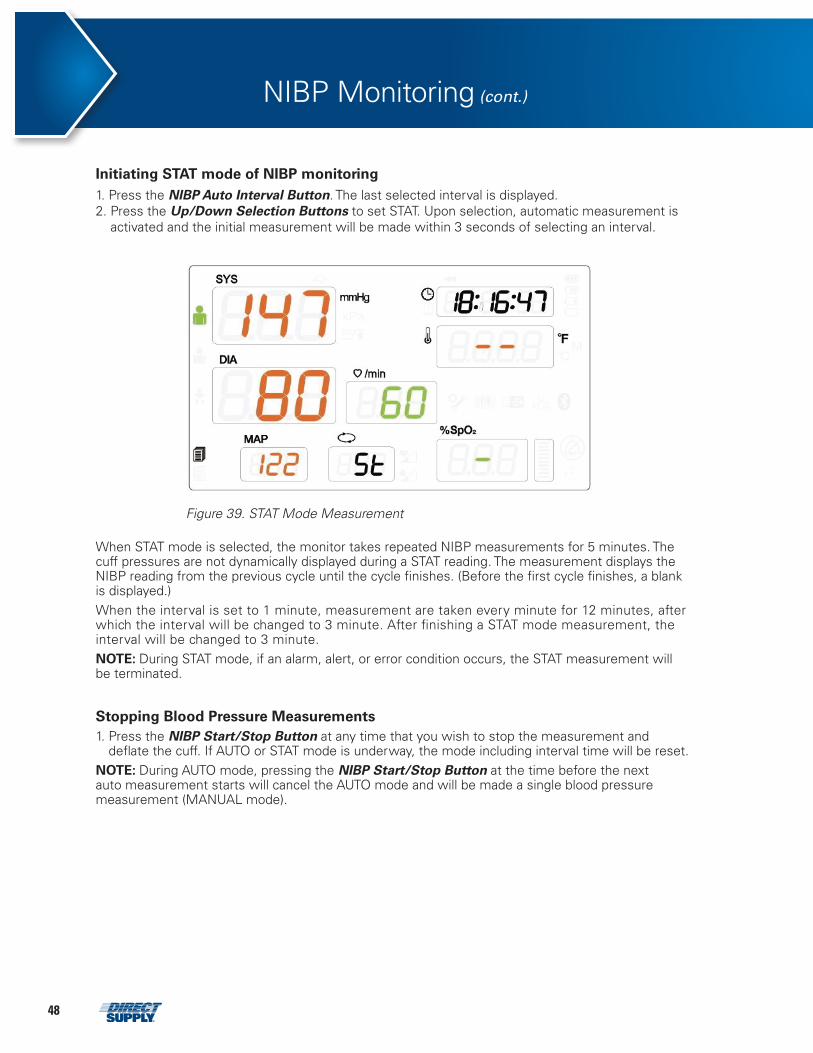
48
Initiating STAT mode of NIBP monitoring 1. Press the NIBP Auto Interval Button. The last selected interval is displayed. 2. Press the Up/Down Selection Buttons to set STAT. Upon selection, automatic measurement is
activated and the initial measurement will be made within 3 seconds of selecting an interval.
NIBP Monitoring (cont.)
attachments 30 – Figure 39. STAT Mode Measurement
Figure 39. STAT Mode Measurement
When STAT mode is selected, the monitor takes repeated NIBP measurements for 5 minutes. The cuff pressures are not dynamically displayed during a STAT reading. The measurement displays the NIBP reading from the previous cycle until the cycle finishes. (Before the first cycle finishes, a blank is displayed.) When the interval is set to 1 minute, measurement are taken every minute for 12 minutes, after which the interval will be changed to 3 minute. After finishing a STAT mode measurement, the interval will be changed to 3 minute. NOTE: During STAT mode, if an alarm, alert, or error condition occurs, the STAT measurement will be terminated.
Stopping Blood Pressure Measurements 1. Press the NIBP Start/Stop Button at any time that you wish to stop the measurement and
deflate the cuff. If AUTO or STAT mode is underway, the mode including interval time will be reset. NOTE: During AUTO mode, pressing the NIBP Start/Stop Button at the time before the next auto measurement starts will cancel the AUTO mode and will be made a single blood pressure measurement (MANUAL mode).
491-800-634-7328 DirectSupply.com
SpO2 Monitoring
• WARNING: Use only accessories intended for use with this monitor. Use accessories according to the manufacturer’s directions for use and your facility’s standards.
• WARNING: Tissue damage can be caused by incorrect application or use of an SpO2 sensor. Harm can be caused, for example, by wrapping the sensor too tightly, by applying supplemental tape, or by leaving a sensor on too long in one place. Inspect the sensor site as directed in the sensor directions for use to ensure skin integrity, correct positioning and adhesion of the sensor.
• WARNING: Do not use damaged SpO2 sensors. Do not use a SpO2 sensor with exposed optical components. Do not immerse sensor completely in water, solvents, or cleaning solutions because the sensor and connectors are not waterproof. Do not sterilize SpO2 sensors by irradiation, steam or ethylene oxide. Refer to the cleaning instructions in the directions for use for reusable SpO2 sensors.
• WARNING: Inaccurate measurements may be caused by: • incorrect sensor application or use • significant levels of dysfunctional hemoglobin (such as carboxyhemoglobin or methemoglobin) • intravascular dyes such as indocyanine green or methylene blue • exposure to excessive illumination, such as surgical lamps (especially ones with a xenon light
source), bilirubin lamps, fluorescent lights, infrared heating lamps, or direct sunlight • excessive resident movement • high-frequency electrosurgical interference and defibrillators • venous pulsations • placement of a sensor on an extremity with a blood pressure cuff, arterial catheter, or intravascular line • resident conditions such as hypotension, severe vasoconstriction, severe anemia, hypothermia,
cardiac arrest or shock • arterial occlusion proximal to the sensor • unspecified environmental conditions • unspecified length of the extension cable
• WARNING: Do not attach any cable to the sensor port connector that is intended for computer use.
• WARNING: Use only pulse oximetry sensors and pulse oximetry cables intended for use with this monitor when connecting to the sensor connector. Connecting any other cable or sensor influences the accuracy of the sensor data, which may lead to adverse results.
• WARNING: Misapplied sensors with excessive pressure for prolonged periods may damage the resident.
• WARNING: Do not use any other cables to extend the length of the approved interface cable. Increasing the length will degrade signal quality and may lead to inaccurate measurements.
• CAUTION: The sensor disconnect error code and associated alarm indicate the sensor is either disconnected or the wiring is faulty. Check the sensor connection and, if necessary, replace the sensor, extension cable or both.
• CAUTION: Reusable sensors may be used on the same site for a maximum of 4 hours, provided the site is inspected routinely to ensure skin integrity and correct positioning.
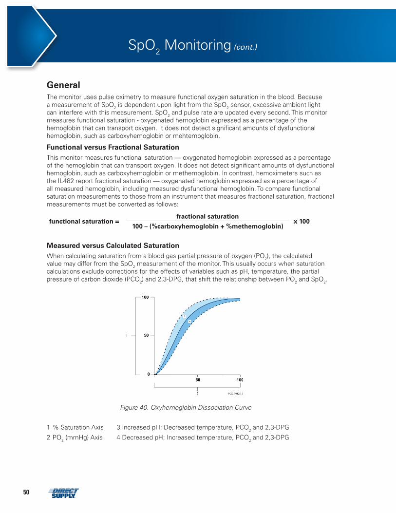
50
General The monitor uses pulse oximetry to measure functional oxygen saturation in the blood. Because a measurement of SpO2 is dependent upon light from the SpO2 sensor, excessive ambient light can interfere with this measurement. SpO2 and pulse rate are updated every second. This monitor measures functional saturation - oxygenated hemoglobin expressed as a percentage of the hemoglobin that can transport oxygen. It does not detect significant amounts of dysfunctional hemoglobin, such as carboxyhemoglobin or mehtemoglobin.
Functional versus Fractional Saturation This monitor measures functional saturation — oxygenated hemoglobin expressed as a percentage of the hemoglobin that can transport oxygen. It does not detect significant amounts of dysfunctional hemoglobin, such as carboxyhemoglobin or methemoglobin. In contrast, hemoximeters such as the IL482 report fractional saturation — oxygenated hemoglobin expressed as a percentage of all measured hemoglobin, including measured dysfunctional hemoglobin. To compare functional saturation measurements to those from an instrument that measures fractional saturation, fractional measurements must be converted as follows:
functional saturation = fractional saturation
x 100100 – (%carboxyhemoglobin + %methemoglobin)
Measured versus Calculated Saturation When calculating saturation from a blood gas partial pressure of oxygen (PO2), the calculated value may differ from the SpO2 measurement of the monitor. This usually occurs when saturation calculations exclude corrections for the effects of variables such as pH, temperature, the partial pressure of carbon dioxide (PCO2) and 2,3-DPG, that shift the relationship between PO2 and SpO2.
Figure 40. Oxyhemoglobin Dissociation Curve
1 % Saturation Axis 3 Increased pH; Decreased temperature, PCO2 and 2,3-DPG
2 PO2 (mmHg) Axis 4 Decreased pH; Increased temperature, PCO2 and 2,3-DPG
SpO2 Monitoring (cont.)
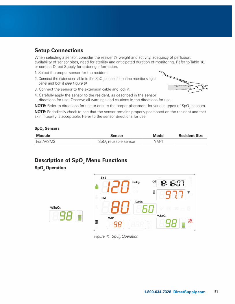
511-800-634-7328 DirectSupply.com
Setup Connections When selecting a sensor, consider the resident’s weight and activity, adequacy of perfusion, availability of sensor sites, need for sterility and anticipated duration of monitoring. Refer to Table 18, or contact Direct Supply for ordering information.
1. Select the proper sensor for the resident.
2. Connect the extension cable to the SpO2 connector on the monitor’s right panel and lock it (see Figure 8).
3. Connect the sensor to the extension cable and lock it.
4. Carefully apply the sensor to the resident, as described in the sensor directions for use. Observe all warnings and cautions in the directions for use.
NOTE: Refer to directions for use to ensure the proper placement for various types of SpO2 sensors.
NOTE: Periodically check to see that the sensor remains properly positioned on the resident and that skin integrity is acceptable. Refer to the sensor directions for use.
SpO2 Sensors
Module Sensor Model Resident Size
For AVSM2 SpO2 reusable sensor YM-1
Description of SpO2 Menu Functions SpO2 Operation
attachments 31 – Figure 42. SpO2 Operation
Figure 41. SpO2 Operation
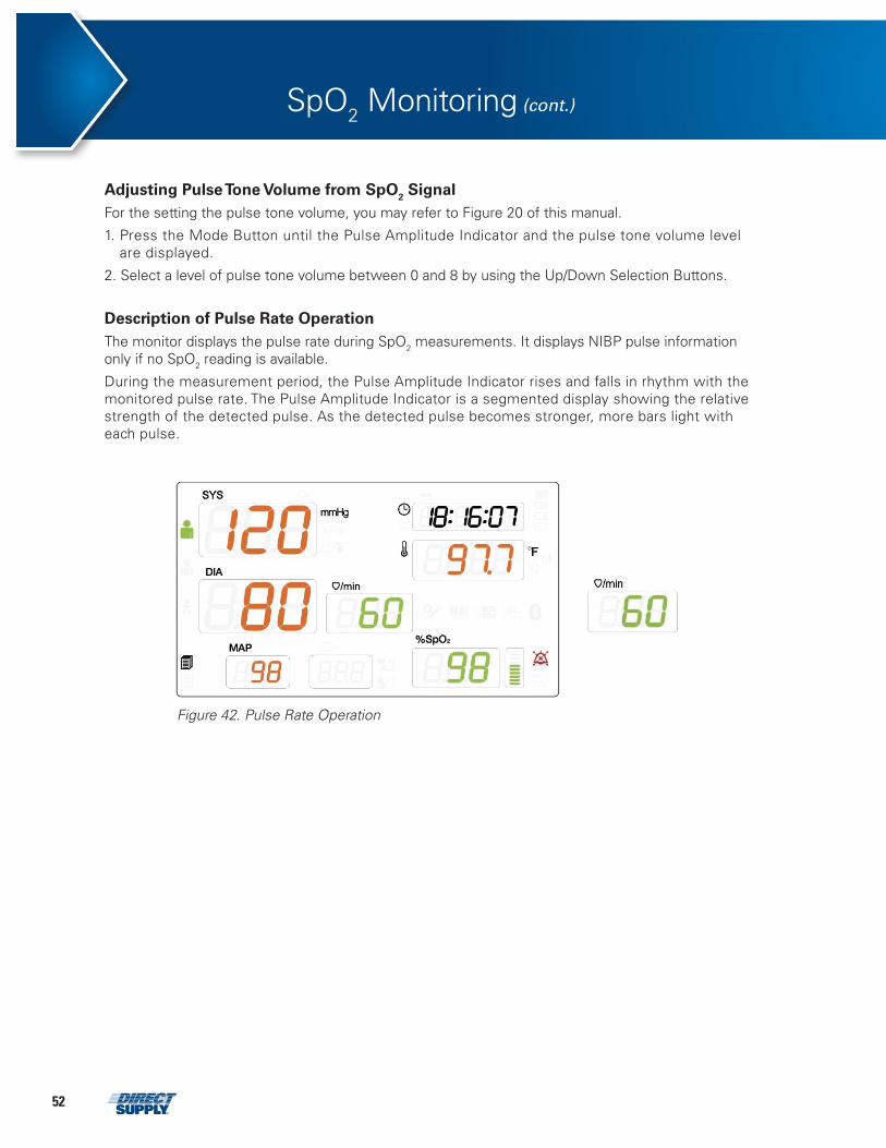
52
SpO2 Monitoring (cont.)
attachments 32 – Figure 43. Pulse Rate Operation
Figure 42. Pulse Rate Operation
Adjusting Pulse Tone Volume from SpO2 Signal For the setting the pulse tone volume, you may refer to Figure 20 of this manual.
1. Press the Mode Button until the Pulse Amplitude Indicator and the pulse tone volume level are displayed.
2. Select a level of pulse tone volume between 0 and 8 by using the Up/Down Selection Buttons.
Description of Pulse Rate Operation The monitor displays the pulse rate during SpO2 measurements. It displays NIBP pulse information only if no SpO2 reading is available.
During the measurement period, the Pulse Amplitude Indicator rises and falls in rhythm with the monitored pulse rate. The Pulse Amplitude Indicator is a segmented display showing the relative strength of the detected pulse. As the detected pulse becomes stronger, more bars light with each pulse.
531-800-634-7328 DirectSupply.com
Temperature Monitoring
• WARNING: Use only the Turbo Temp and Genius 2 temperature probes with the monitor. Use accessories according to the manufacturer’s directions for use and your facility’s standards.
NOTE: The user should check that the monitor is functioning while measurements are being made and also check display periodically.
General Two types of thermometry sensors are available for measuring temperature. One is the Alaris Turbo Temp oral thermometry probe and the other is the Covidien Genius 2 tympanic thermometry probe.
Turbo Temp thermometry probe: Measurement of body temperature is accomplished by processing the signal from a probe containing a resistance element whose impedance is temperature dependent. These devices are called thermistors.
Genius 2 thermometry probe: The other measurement of body temperature is an ear canal thermometer with measurement site equivalence modes including oral, core, and rectal equivalent temperatures. These devices are called infrared ear thermometers.
Temperature Measurement Modes
Temperature measurement can be made in two modes: predictive mode or continuous monitoring mode.
Predictive Mode One-time measurement that takes only a few seconds. It results in a single temperature reading which is displayed at the end of the brief measurement period (with both Turbo Temp and Genius 2 thermometry probes).
Continuous Monitoring Mode Continuous measurement mode over an indefinite period. The temperature is displayed dynamically throughout the measurement period. (Turbo Temp thermometry probe only.)
Measurement Method Turbo Temp Thermometer Mounting the Probe Cover
Always mount the probe cover before using the body temperature probe. A probe cover is required to take a body temperature measurement. Press the probe firmly into the probe cover, being careful not to press the probe cover release on the top of the probe. If the probe cover is not securely mounted, there is a danger of it coming loose or coming off during use.
For oral measurement 1. Use the probe with a blue cap. 2. Insert the probe completely and firmly into a probe cover to ensure a secure fit. 3. Place the tip of the probe in the hollow under the tongue. 4. After about 10 seconds, the body temperature can be measured. • Hold the probe in such a way that its tip is touching the skin in the mouth during an oral
temperature measurement. • During oral temperature measurement, do not change the position of the oral temperature
probe or have the resident hold it.
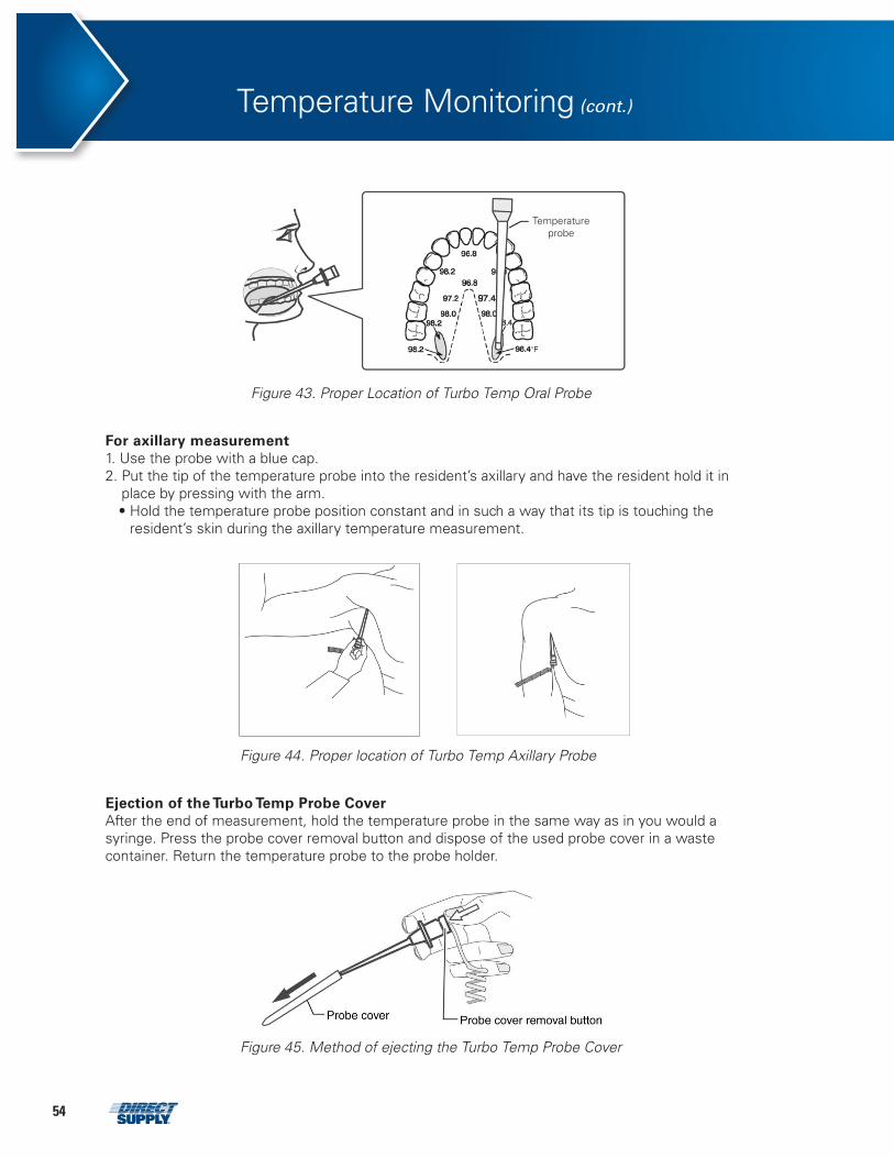
54
Temperature Monitoring (cont.)
Figure 43. Proper Location of Turbo Temp Oral Probe
For axillary measurement 1. Use the probe with a blue cap. 2. Put the tip of the temperature probe into the resident’s axillary and have the resident hold it in
place by pressing with the arm. • Hold the temperature probe position constant and in such a way that its tip is touching the
resident’s skin during the axillary temperature measurement.
Figure 44. Proper location of Turbo Temp Axillary Probe
Ejection of the Turbo Temp Probe Cover After the end of measurement, hold the temperature probe in the same way as in you would a syringe. Press the probe cover removal button and dispose of the used probe cover in a waste container. Return the temperature probe to the probe holder.
Figure 45. Method of ejecting the Turbo Temp Probe Cover
Temperature probe
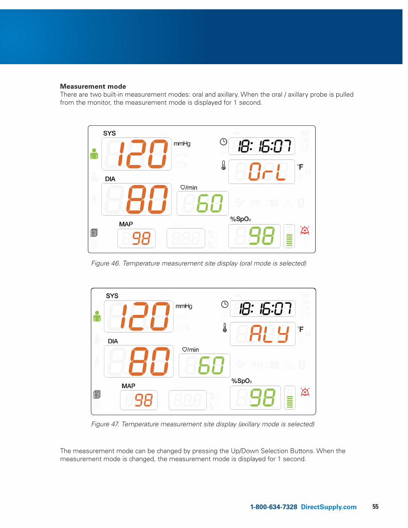
551-800-634-7328 DirectSupply.com
Measurement mode There are two built-in measurement modes: oral and axillary. When the oral / axillary probe is pulled from the monitor, the measurement mode is displayed for 1 second.
Figure 46. Temperature measurement site display (oral mode is selected)
Figure 47. Temperature measurement site display (axillary mode is selected)
The measurement mode can be changed by pressing the Up/Down Selection Buttons. When the measurement mode is changed, the measurement mode is displayed for 1 second.
attachments 33 – Figure 47. Temperature Measurement Site Display (Oral probe is installed)
attachments 34 – Figure 48. Temperature Measurement Part Display (Axillary probe is installed)
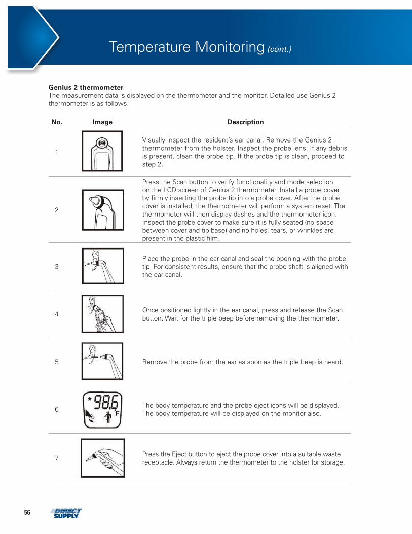
56
Genius 2 thermometer The measurement data is displayed on the thermometer and the monitor. Detailed use Genius 2 thermometer is as follows.
No. Image Description
1
Visually inspect the resident’s ear canal. Remove the Genius 2 thermometer from the holster. Inspect the probe lens. If any debris is present, clean the probe tip. If the probe tip is clean, proceed to step 2.
2
Press the Scan button to verify functionality and mode selection on the LCD screen of Genius 2 thermometer. Install a probe cover by firmly inserting the probe tip into a probe cover. After the probe cover is installed, the thermometer will perform a system reset. The thermometer will then display dashes and the thermometer icon. Inspect the probe cover to make sure it is fully seated (no space between cover and tip base) and no holes, tears, or wrinkles are present in the plastic film.
3
Place the probe in the ear canal and seal the opening with the probe tip. For consistent results, ensure that the probe shaft is aligned with the ear canal.
4
Once positioned lightly in the ear canal, press and release the Scan button. Wait for the triple beep before removing the thermometer.
5
Remove the probe from the ear as soon as the triple beep is heard.
6
The body temperature and the probe eject icons will be displayed. The body temperature will be displayed on the monitor also.
7
Press the Eject button to eject the probe cover into a suitable waste receptacle. Always return the thermometer to the holster for storage.
Temperature Monitoring (cont.)
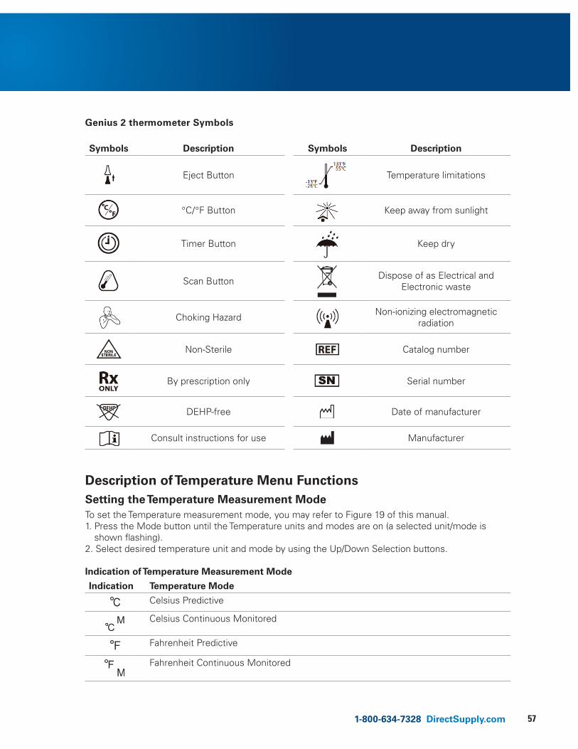
571-800-634-7328 DirectSupply.com
Genius 2 thermometer Symbols
Symbols Description Symbols Description
Eject Button
Temperature limitations
°C/°F Button
Keep away from sunlight
Timer Button
Keep dry
Scan Button
Dispose of as Electrical and Electronic waste
Choking Hazard
Non-ionizing electromagnetic radiation
Non-Sterile
Catalog number
By prescription only
Serial number
DEHP-free
Date of manufacturer
Consult instructions for use
Manufacturer
Description of Temperature Menu Functions
Setting the Temperature Measurement Mode To set the Temperature measurement mode, you may refer to Figure 19 of this manual. 1. Press the Mode button until the Temperature units and modes are on (a selected unit/mode is
shown flashing). 2. Select desired temperature unit and mode by using the Up/Down Selection buttons.
Indication of Temperature Measurement Mode
Indication Temperature Mode
Celsius Predictive
Celsius Continuous Monitored
Fahrenheit Predictive
Fahrenheit Continuous Monitored
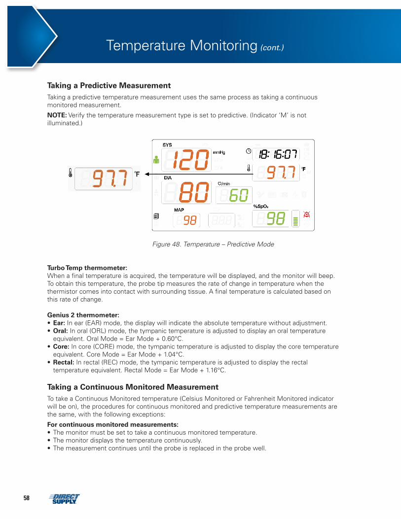
58
Turbo Temp thermometer: When a final temperature is acquired, the temperature will be displayed, and the monitor will beep. To obtain this temperature, the probe tip measures the rate of change in temperature when the thermistor comes into contact with surrounding tissue. A final temperature is calculated based on this rate of change.
Genius 2 thermometer: • Ear: In ear (EAR) mode, the display will indicate the absolute temperature without adjustment.• Oral: In oral (ORL) mode, the tympanic temperature is adjusted to display an oral temperature
equivalent. Oral Mode = Ear Mode + 0.60°C.• Core: In core (CORE) mode, the tympanic temperature is adjusted to display the core temperature
equivalent. Core Mode = Ear Mode + 1.04°C.• Rectal: In rectal (REC) mode, the tympanic temperature is adjusted to display the rectal
temperature equivalent. Rectal Mode = Ear Mode + 1.16°C.
Taking a Continuous Monitored Measurement To take a Continuous Monitored temperature (Celsius Monitored or Fahrenheit Monitored indicator will be on), the procedures for continuous monitored and predictive temperature measurements are the same, with the following exceptions:
For continuous monitored measurements: • The monitor must be set to take a continuous monitored temperature. • The monitor displays the temperature continuously. • The measurement continues until the probe is replaced in the probe well.
Taking a Predictive Measurement Taking a predictive temperature measurement uses the same process as taking a continuous monitored measurement.
NOTE: Verify the temperature measurement type is set to predictive. (Indicator ‘M’ is not illuminated.)
attachments 35 – Figure 49. Temperature – Predictive Mode
Figure 48. Temperature – Predictive Mode
Temperature Monitoring (cont.)
591-800-634-7328 DirectSupply.com
NOTE: Verify the temperature measurement type is set to continuous monitoring mode If the measured temperature remains below the minimum measurable temperature for 5 minutes, the temperature cycle is terminated and the temperature display goes blank. To reactivate the probe, insert it into the probe well after discarding the used probe cover, remove it from the probe well, and attach a new probe cover.
Probe Decontamination Procedure (Predictive / Continuous Monitored Measurement) 1. Turn the monitor off. 2. Unplug the latching probe connector from the monitor. 3. Remove the probe from the probe well. 4. Remove the probe well from the monitor. 5. Clean the probe and the inner and outer surface of the probe well by swabbing with a cloth
dampened with 70% isopropyl alcohol or a 10% solution of chlorine bleach.
NOTE: Do not immerse or soak the probe in any type of fluid.
NOTE: Do not autoclave the probe.
NOTE: Do not use steam, heat, or gas sterilization of the probe or probe well.
NOTE: Do not use hard or sharp objects to clean the probe well. Hard or sharp objects can damage the probe well, which could cause the monitor to fail.
NOTE: Do not autoclave the probe well.
6. Thoroughly dry all surfaces before reassembling the monitor. 7. Reinstall the probe well in the monitor. 8. Insert the probe into the probe well. 9. Reconnect the probe latching connector to the monitor, making sure that the connector snaps
into place.
NOTE: Disposable single use probe covers aid in the prevention of a cross contamination of infectious diseases. Always install a new probe cover prior to taking a temperature.
60
General Trend data is stored in internal memory. The monitor saves all physiological and technical alarms. The monitor also saves all NIBP, temperature, and SpO2 measurements. For SpO2 and continuous monitored Temperature measurements, the monitor saves data every 1 minute. If a parameter limit alarm occurs, the monitor immediate saves the reading. If a loss of pulse is detected, the most recent successfully acquired measurement is saved. After the monitor has stored 2,000 sets of trend data, any new stored measurements overwrite previously stored measurements, starting with the oldest measurements first.
Trend Data Printout All of the trend data stored in internal memory is printed if the Print Start/Stop Button is pressed in Review Mode and the monitor is set to stream print. Trend data (1 page) indicated on Review mode display is printed if the print button is pressed in Review Mode and the monitor is set to manual print state.
Follow the instructions below to print stored data if an optional printer is installed. 1. Press Print Start/Stop Button when the monitor is in Review mode to display stored data on the
monitor display. • If the monitor is not printing, press the Print Start/Stop Button to start printing. • If the monitor is printing, press the Print Start/Stop Button to stop printing. NOTE: The Print Start/Stop Button is disabled during an NIBP cycle.
Displaying Stored Resident Data 1. Press the Review Button to display the newest stored set of resident vital-signs data. • Pressing the Review button interrupts the measurement process. • After pressing the Review button, the most recent set of measurement data, including NIBP,
SpO2, Pulse rate, Temperature, time, date and the dataset sequence number is displayed. • If the Review button is pressed again, the next most recent stored data set is displayed. 2. Press the Up/Down Selection Button to cycle backward (scroll) through the stored measurement
data sets. (The monitor stores 1000 measurement cycles.) 3. To stop reviewing data and return to Normal mode, press any button other than the Review button
or the Up/Down Selection button. 4. The monitor will return to Normal mode if 5 seconds pass without any button presses.
Erasing Resident Data • CAUTION: To prevent data leakage, erase any resident data before disposing of the monitor.
To erase stored resident; 1. Enter Review Mode.2. Press and hold the Review Button for 3 seconds. The stored data will be erased, and the monitor
will return to Normal mode.
Trend Data Download Connect the micro 5-pin USB port to the monitor and connect the connector of micro 5-pin USB port cable to a PC for downloading trend data. The types of data output methods are Serial communication (Mini USB), Ethernet communication (LAN) and wireless communication (Bluetooth).
NOTE: Contact Direct Supply for more information about wired and wireless data transfer.
Trends
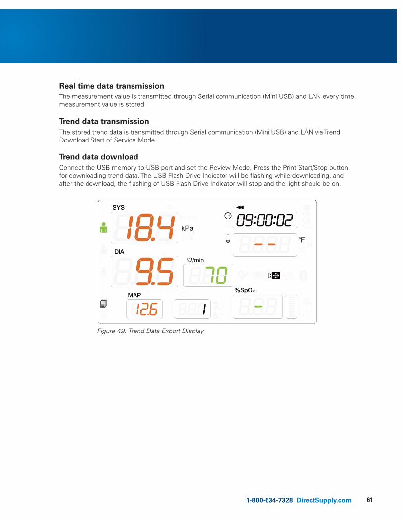
611-800-634-7328 DirectSupply.com
Real time data transmission The measurement value is transmitted through Serial communication (Mini USB) and LAN every time measurement value is stored.
Trend data transmission The stored trend data is transmitted through Serial communication (Mini USB) and LAN via Trend Download Start of Service Mode.
Trend data download Connect the USB memory to USB port and set the Review Mode. Press the Print Start/Stop button for downloading trend data. The USB Flash Drive Indicator will be flashing while downloading, and after the download, the flashing of USB Flash Drive Indicator will stop and the light should be on.
attachments 36 – Figure 50. Trend Data Export Display
Figure 49. Trend Data Export Display
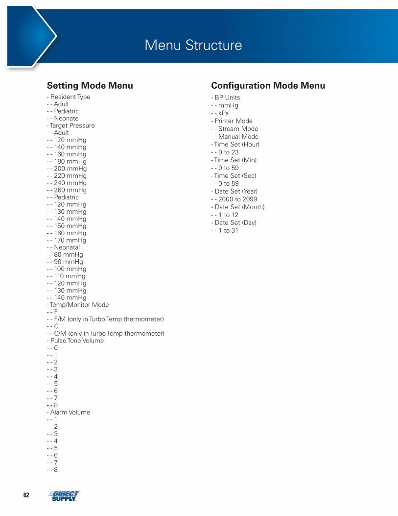
62
Menu Structure
Setting Mode Menu - Resident Type - - Adult - - Pediatric - - Neonate - Target Pressure - - Adult - - 120 mmHg - - 140 mmHg - - 160 mmHg - - 180 mmHg - - 200 mmHg - - 220 mmHg - - 240 mmHg - - 260 mmHg - - Pediatric - - 120 mmHg - - 130 mmHg - - 140 mmHg - - 150 mmHg - - 160 mmHg - - 170 mmHg - - Neonatal - - 80 mmHg - - 90 mmHg - - 100 mmHg - - 110 mmHg - - 120 mmHg - - 130 mmHg - - 140 mmHg - Temp/Monitor Mode - - F - - F/M (only in Turbo Temp thermometer) - - C - - C/M (only in Turbo Temp thermometer) - Pulse Tone Volume - - 0 - - 1 - - 2 - - 3 - - 4 - - 5 - - 6 - - 7 - - 8 - Alarm Volume - - 1 - - 2 - - 3 - - 4 - - 5- - 6 - - 7 - - 8
Configuration Mode Menu
- BP Units - - mmHg - - kPa - Printer Mode - - Stream Mode - - Manual Mode - Time Set (Hour) - - 0 to 23 - Time Set (Min) - - 0 to 59 - Time Set (Sec) - - 0 to 59 - Date Set (Year) - - 2000 to 2099 - Date Set (Month) - - 1 to 12 - Date Set (Day) - - 1 to 31
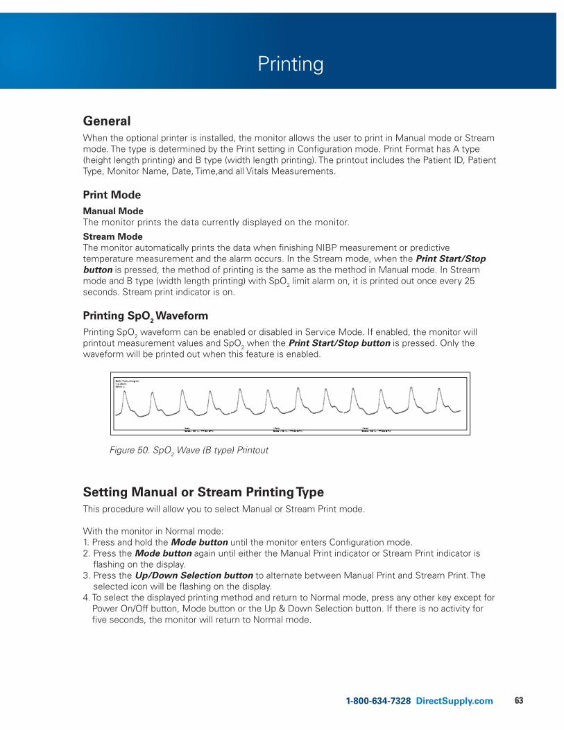
631-800-634-7328 DirectSupply.com
Printing
General When the optional printer is installed, the monitor allows the user to print in Manual mode or Stream mode. The type is determined by the Print setting in Configuration mode. Print Format has A type (height length printing) and B type (width length printing). The printout includes the Patient ID, Patient Type, Monitor Name, Date, Time,and all Vitals Measurements.
Print Mode Manual Mode The monitor prints the data currently displayed on the monitor.
Stream Mode The monitor automatically prints the data when finishing NIBP measurement or predictive temperature measurement and the alarm occurs. In the Stream mode, when the Print Start/Stop button is pressed, the method of printing is the same as the method in Manual mode. In Stream mode and B type (width length printing) with SpO2 limit alarm on, it is printed out once every 25 seconds. Stream print indicator is on.
Printing SpO2 Waveform Printing SpO2 waveform can be enabled or disabled in Service Mode. If enabled, the monitor will printout measurement values and SpO2 when the Print Start/Stop button is pressed. Only the waveform will be printed out when this feature is enabled.
Figure 50. SpO2 Wave (B type) Printout
Setting Manual or Stream Printing Type This procedure will allow you to select Manual or Stream Print mode.
With the monitor in Normal mode: 1. Press and hold the Mode button until the monitor enters Configuration mode. 2. Press the Mode button again until either the Manual Print indicator or Stream Print indicator is
flashing on the display. 3. Press the Up/Down Selection button to alternate between Manual Print and Stream Print. The
selected icon will be flashing on the display. 4. To select the displayed printing method and return to Normal mode, press any other key except for
Power On/Off button, Mode button or the Up & Down Selection button. If there is no activity for five seconds, the monitor will return to Normal mode.
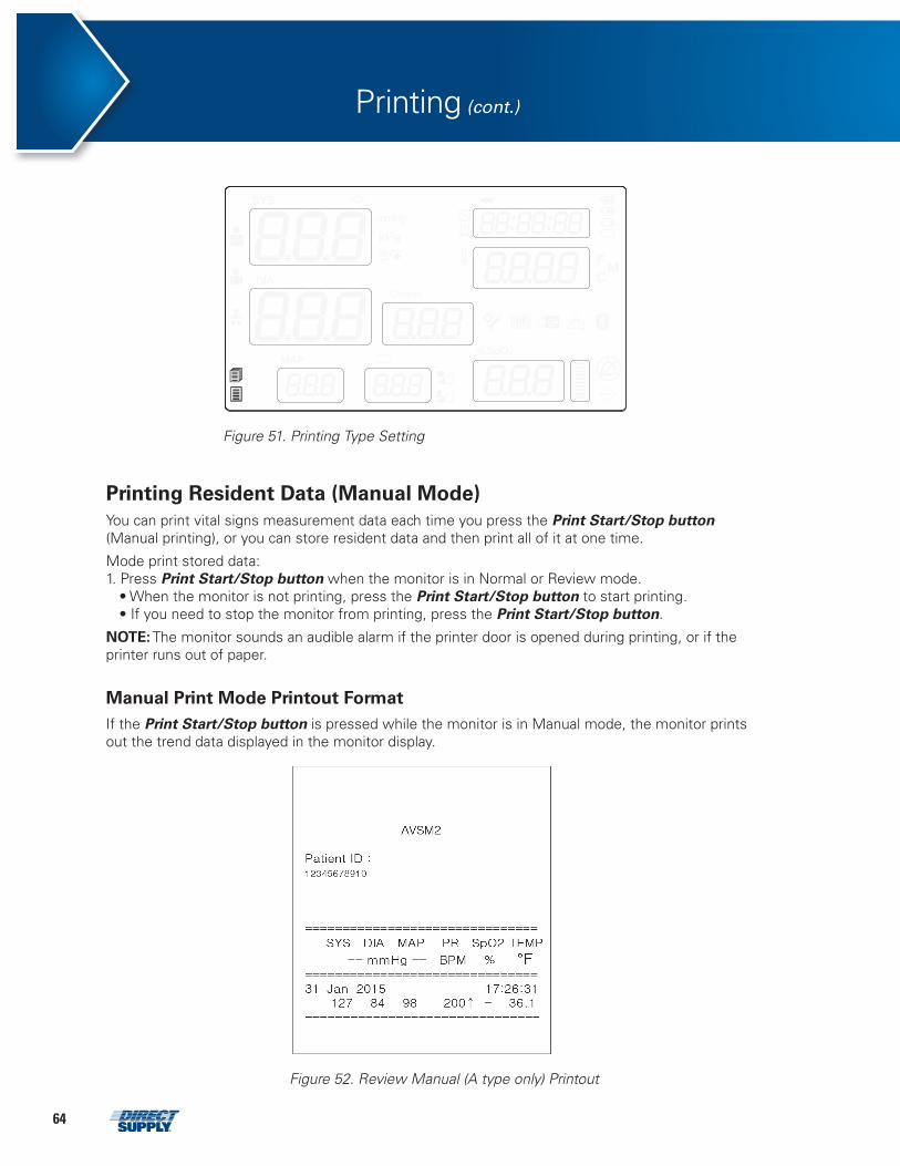
64
Printing Resident Data (Manual Mode) You can print vital signs measurement data each time you press the Print Start/Stop button (Manual printing), or you can store resident data and then print all of it at one time.
Mode print stored data: 1. Press Print Start/Stop button when the monitor is in Normal or Review mode. • When the monitor is not printing, press the Print Start/Stop button to start printing. • If you need to stop the monitor from printing, press the Print Start/Stop button.
NOTE: The monitor sounds an audible alarm if the printer door is opened during printing, or if the printer runs out of paper.
Manual Print Mode Printout Format If the Print Start/Stop button is pressed while the monitor is in Manual mode, the monitor prints out the trend data displayed in the monitor display.
attachments 37 – Figure 52. Printing Mode Setting
Figure 51. Printing Type Setting
Figure 52. Review Manual (A type only) Printout
Printing (cont.)
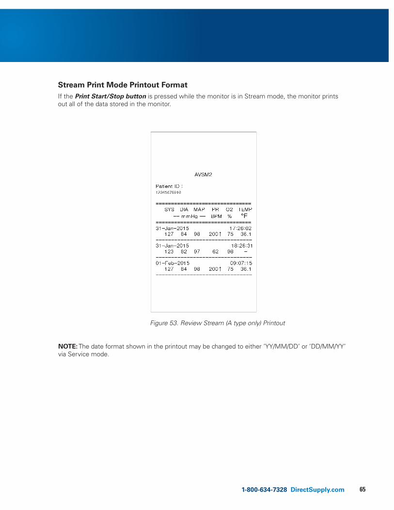
651-800-634-7328 DirectSupply.com
Stream Print Mode Printout Format If the Print Start/Stop button is pressed while the monitor is in Stream mode, the monitor prints out all of the data stored in the monitor.
Figure 53. Review Stream (A type only) Printout
NOTE: The date format shown in the printout may be changed to either ’YY/MM/DD’ or ’DD/MM/YY’ via Service mode.
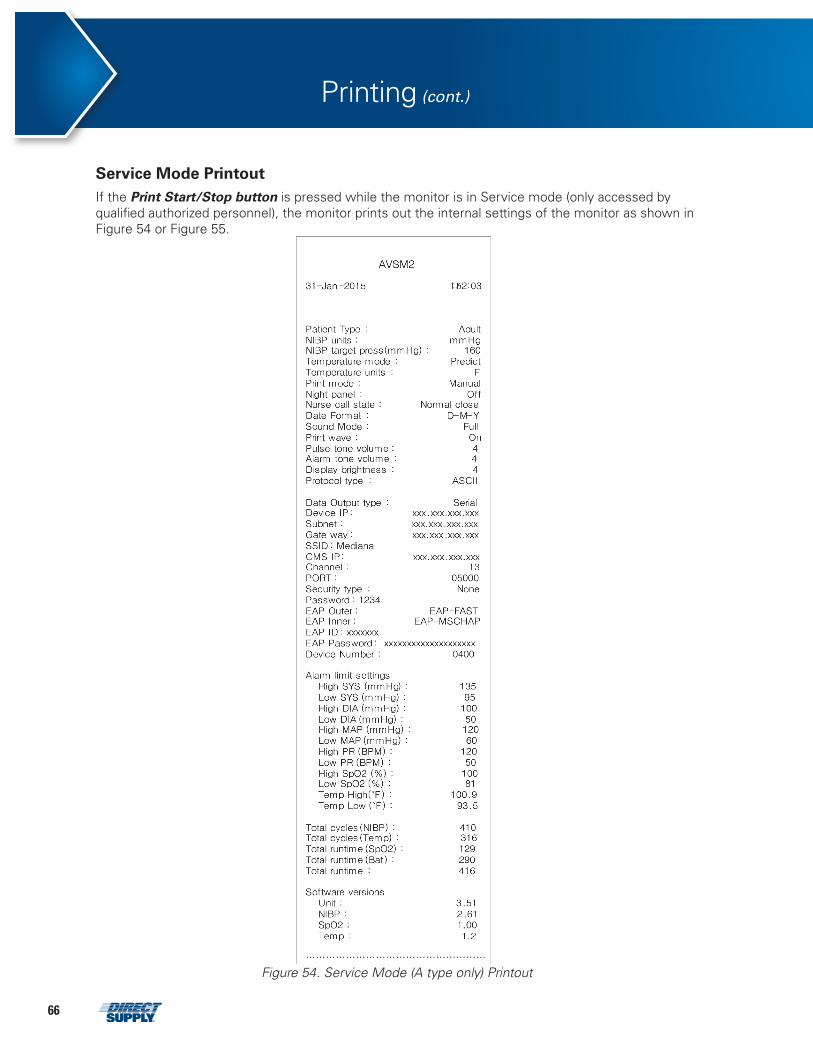
66
Service Mode Printout If the Print Start/Stop button is pressed while the monitor is in Service mode (only accessed by qualified authorized personnel), the monitor prints out the internal settings of the monitor as shown in Figure 54 or Figure 55.
Printing (cont.)
Figure 54. Service Mode (A type only) Printout
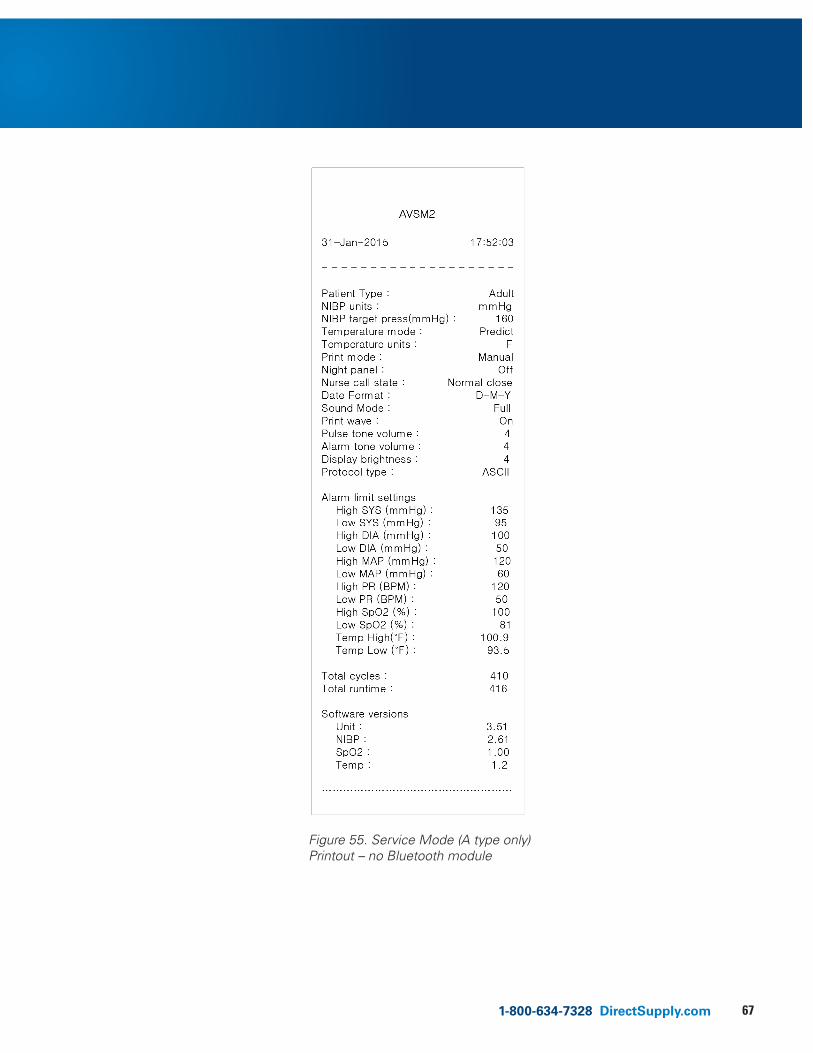
671-800-634-7328 DirectSupply.com
Figure 55. Service Mode (A type only) Printout – no Bluetooth module
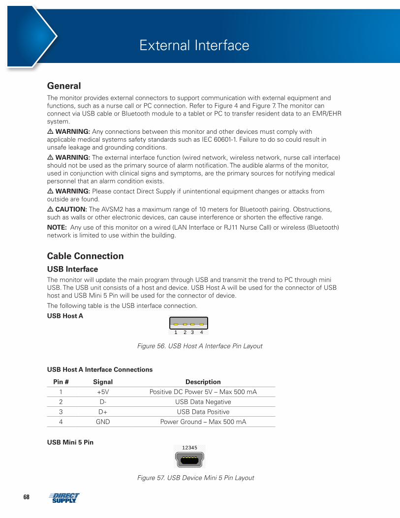
68
External Interface
General The monitor provides external connectors to support communication with external equipment and functions, such as a nurse call or PC connection. Refer to Figure 4 and Figure 7. The monitor can connect via USB cable or Bluetooth module to a tablet or PC to transfer resident data to an EMR/EHR system.
• WARNING: Any connections between this monitor and other devices must comply with applicable medical systems safety standards such as IEC 60601-1. Failure to do so could result in unsafe leakage and grounding conditions.
• WARNING: The external interface function (wired network, wireless network, nurse call interface) should not be used as the primary source of alarm notification. The audible alarms of the monitor, used in conjunction with clinical signs and symptoms, are the primary sources for notifying medical personnel that an alarm condition exists.
• WARNING: Please contact Direct Supply if unintentional equipment changes or attacks from outside are found.
• CAUTION: The AVSM2 has a maximum range of 10 meters for Bluetooth pairing. Obstructions, such as walls or other electronic devices, can cause interference or shorten the effective range.
NOTE: Any use of this monitor on a wired (LAN Interface or RJ11 Nurse Call) or wireless (Bluetooth) network is limited to use within the building.
Cable Connection USB Interface The monitor will update the main program through USB and transmit the trend to PC through mini USB. The USB unit consists of a host and device. USB Host A will be used for the connector of USB host and USB Mini 5 Pin will be used for the connector of device.
The following table is the USB interface connection.
USB Host A
Figure 56. USB Host A Interface Pin Layout
USB Host A Interface Connections
Pin # Signal Description
1 +5V Positive DC Power 5V – Max 500 mA
2 D- USB Data Negative
3 D+ USB Data Positive
4 GND Power Ground – Max 500 mA
USB Mini 5 Pin
1 2 3 4 5 6
Figure 57. USB Device Mini 5 Pin Layout
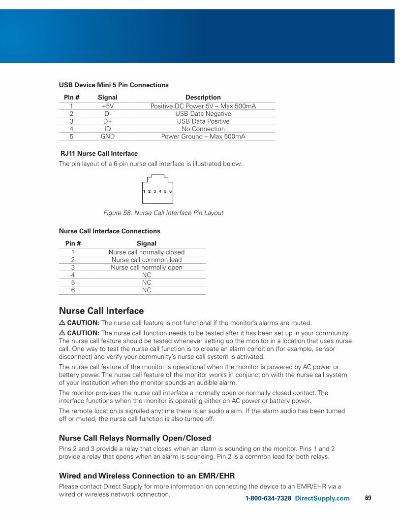
691-800-634-7328 DirectSupply.com
USB Device Mini 5 Pin Connections
Pin # Signal Description 1 +5V Positive DC Power 5V – Max 500mA 2 D- USB Data Negative 3 D+ USB Data Positive 4 ID No Connection 5 GND Power Ground – Max 500mA
RJ11 Nurse Call Interface
The pin layout of a 6-pin nurse call interface is illustrated below.
1 2 3 4 5 6
Figure 58. Nurse Call Interface Pin Layout
Nurse Call Interface Connections
Pin # Signal 1 Nurse call normally closed 2 Nurse call common lead 3 Nurse call normally open 4 NC 5 NC 6 NC
Nurse Call Interface• CAUTION: The nurse call feature is not functional if the monitor’s alarms are muted.
• CAUTION: The nurse call function needs to be tested after it has been set up in your community. The nurse call feature should be tested whenever setting up the monitor in a location that uses nurse call. One way to test the nurse call function is to create an alarm condition (for example, sensor disconnect) and verify your community’s nurse call system is activated.
The nurse call feature of the monitor is operational when the monitor is powered by AC power or battery power. The nurse call feature of the monitor works in conjunction with the nurse call system of your institution when the monitor sounds an audible alarm.
The monitor provides the nurse call interface a normally open or normally closed contact. The interface functions when the monitor is operating either on AC power or battery power.
The remote location is signaled anytime there is an audio alarm. If the alarm audio has been turned off or muted, the nurse call function is also turned off.
Nurse Call Relays Normally Open/Closed Pins 2 and 3 provide a relay that closes when an alarm is sounding on the monitor. Pins 1 and 2 provide a relay that opens when an alarm is sounding. Pin 2 is a common lead for both relays.
Wired and Wireless Connection to an EMR/EHRPlease contact Direct Supply for more information on connecting the device to an EMR/EHR via a wired or wireless network connection.
70
Maintenance
• WARNING: The cover should be removed only by qualified service personnel. There are no internal user-serviceable parts except for the battery.
• WARNING: Do not spray, pour or spill any liquid on the monitor, its accessories, connectors, switches or openings in the chassis.
• WARNING: Unplug the power cord from the monitor before cleaning the monitor.
• CAUTION: To prevent data leakage, erase any resident data before disposing of the monitor.
Recycling & Disposal When the monitor, battery or accessories reach the end of useful life, recycle or dispose of the equipment according to appropriate local and regional regulations.
NOTE: The monitor should be disposed of separately from the municipal waste stream via designated collection facilities appointed by the government or the local authorities.
NOTE: The correct disposal of your old monitor will help prevent potential negative consequences for the environment and human health.
NOTE: For more detailed information about disposal of your old appliance, please contact your city office, waste disposal service or Direct Supply.
Returning the Monitor and System Components
Pack the monitor with sensors, cable or other accessory items in its original shipping carton. If the original carton is not available, use a suitable carton with appropriate packing material to protect the monitor during shipping.
Service Check the monitor for damage before each use. Do not use if monitor appears to be damaged or malfunctioning in any way.
The monitor requires no routine service other than cleaning, battery maintenance and service activity that is mandated by the user’s community. Qualified service personnel in the user’s community should perform periodic inspections of the monitor. If service is necessary, contact Direct Supply.
Periodic Safety Checks It is recommended that the following checks be performed every year. • Inspect the equipment for mechanical and functional damage. • Inspect the external safety labels for legibility.
Cleaning The monitor may be surface-cleaned by using a soft cloth dampened with either a commercial, nonabrasive cleaner or one of the solutions listed below. Lightly wipe the top, bottom and front surfaces of the monitor. • 70% isopropyl alcohol • 10% chlorine bleach solution
For cables, sensors, cuffs and probes, follow the cleaning instructions in the directions for use shipped with those components.
Avoid spilling liquid on the monitor, especially in connectors. If liquid is accidentally spilled on the monitor, clean and dry thoroughly before reuse. If in doubt about the monitor’s safety, contact Direct Supply to have the monitor checked.
711-800-634-7328 DirectSupply.com
Battery Maintenance• CAUTION: Recharging the battery is strongly recommended when the battery has not been recharged for three or more months.
• CAUTION: Recharging the battery is strongly recommended before using the monitor.
• CAUTION: Follow local government ordinances and recycling instructions regarding disposal or recycling of device components, including battery.
• CAUTION: Do not short-circuit the battery, as it may generate heat. To avoid short-circuiting, do not let the battery come in contact with metal objects at any time, especially when transporting.
• CAUTION: Do not solder the battery directly. Heat applied during soldering may damage the safety vent in the battery’s positive cover.
• CAUTION: Do not deform the battery by applying pressure. Do not throw, hit, drop, fold or impact the battery.
• CAUTION: Do not connect the battery reversed in positive (+) and negative (-) terminals. Do not charge the battery with polarities reversed, as it may swell or explode.
• CAUTION: Do not use any external chargers with the monitor battery.
• CAUTION: Do not use the battery with other manufacturer’s batteries. Using different types or models of batteries together, such as dry batteries, nickel-metal hydride batteries or Li-ion batteries, might cause the battery to leak electrolytes, or cause the battery to overheat or explode.
• CAUTION: Do not damage the battery or use the battery in any other applications.
• CAUTION: Keep the battery out of reach of children to avoid any accidents.
• CAUTION: If there are any problems observed with the battery, immediately store the battery in a safe place and contact Direct Supply.
If the monitor has not been used for three months, the Li-ion battery will need charging. To charge the battery, connect the monitor to an AC power source as described in the Battery Operation section.
NOTE: Storing the monitor for a long period without charging the battery may degrade the battery capacity. A full charge of a depleted battery takes more than 12 hours.
NOTE: The battery should be removed from the monitor if placed in storage, or if it will not be used for a long period of time.
It is recommended that the monitor’s Li-ion battery be replaced if any degradation in performance is observed.
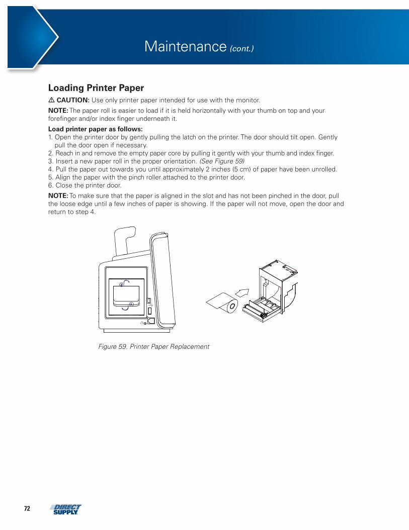
72
Maintenance (cont.)
Loading Printer Paper• CAUTION: Use only printer paper intended for use with the monitor.
NOTE: The paper roll is easier to load if it is held horizontally with your thumb on top and your forefinger and/or index finger underneath it.
Load printer paper as follows: 1. Open the printer door by gently pulling the latch on the printer. The door should tilt open. Gently
pull the door open if necessary. 2. Reach in and remove the empty paper core by pulling it gently with your thumb and index finger. 3. Insert a new paper roll in the proper orientation. (See Figure 59)4. Pull the paper out towards you until approximately 2 inches (5 cm) of paper have been unrolled. 5. Align the paper with the pinch roller attached to the printer door. 6. Close the printer door.
NOTE: To make sure that the paper is aligned in the slot and has not been pinched in the door, pull the loose edge until a few inches of paper is showing. If the paper will not move, open the door and return to step 4.
Figure 59. Printer Paper Replacement
731-800-634-7328 DirectSupply.com
Troubleshooting
• WARNING: If you are uncertain about the accuracy of any measurement, check the resident’s vital signs by alternate means; then test and verify the monitor is functioning correctly.
• WARNING: The cover should be removed only by qualified service personnel. There are no user-serviceable parts inside except for the battery.
General If the monitor detects an error, it will display an error code. The error codes are listed on the label on the top of the monitor. If an error code is displayed, stop using the monitor, write down the code and contact Direct Supply. Before calling Direct Supply, make sure that the battery is charged and that all power connections are in place.
Corrective Action If you experience a problem while using the monitor and are unable to correct it, contact Direct Supply.
Following is a list of possible errors and suggestions for corrective action.
Error Corrective Action
No response to Power On/Off button press.
Press the Power On/Off button. Check the battery installation or AC connection.Check to see if the Battery Charging indicator is lit.If the error continues, contact Direct Supply.
Monitor does not power on with battery.
Check the battery installation. Check to see if the Battery Charging indicator is lit.Recharge the battery for 12 hours. If the problem persists, replace the battery.
Low Battery / Critically Low Battery condition.
Connect the monitor to an AC power source and verify the Battery Charging indicator is lit. Replace the battery with new battery.If the error continues, contact Direct Supply.
Display is deformed or not displayed.
Contact Direct Supply.
No sound. Verify the volume setting is loud enough to hear. Verify the alarm audio is not muted.If the error continues, contact Direct Supply.
Date and time incorrect. Set the date and time from the Date and Time menu. Turn off the monitor, wait a few minutes, then turn on the monitorand verify the date and time.If the error continues, contact Direct Supply.
Abnormal shut down last time.
Contact Direct Supply.
Technical System Error (ex. EEE801~).
Do not use the monitor; contact Direct Supply.
Buzzer-like sound is heard and the monitor cannot be turned off.
Press and hold the Power On/Off button for more than 15 seconds. Contact Direct Supply.
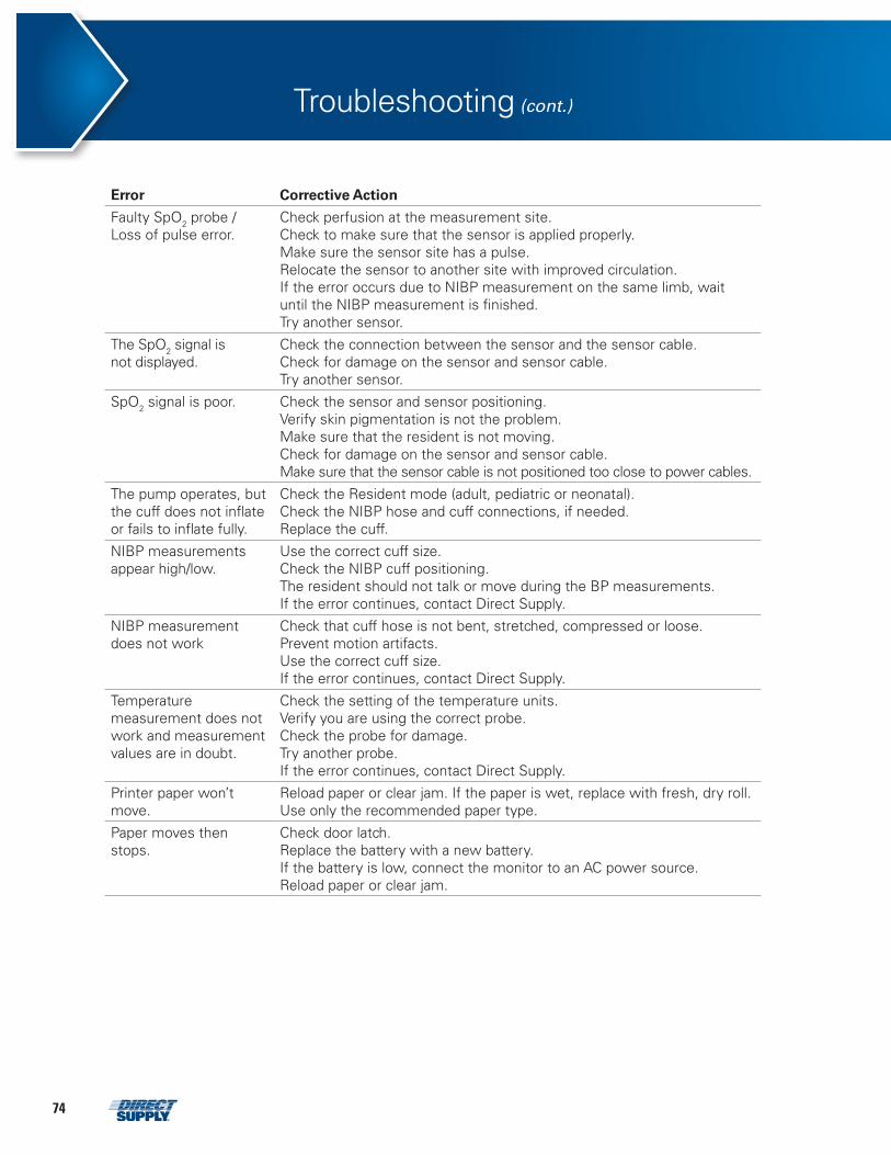
74
Error Corrective Action
Faulty SpO2 probe / Loss of pulse error.
Check perfusion at the measurement site. Check to make sure that the sensor is applied properly.Make sure the sensor site has a pulse.Relocate the sensor to another site with improved circulation.If the error occurs due to NIBP measurement on the same limb, wait until the NIBP measurement is finished.Try another sensor.
The SpO2 signal is not displayed.
Check the connection between the sensor and the sensor cable. Check for damage on the sensor and sensor cable.Try another sensor.
SpO2 signal is poor. Check the sensor and sensor positioning. Verify skin pigmentation is not the problem.Make sure that the resident is not moving.Check for damage on the sensor and sensor cable.Make sure that the sensor cable is not positioned too close to power cables.
The pump operates, but the cuff does not inflate or fails to inflate fully.
Check the Resident mode (adult, pediatric or neonatal). Check the NIBP hose and cuff connections, if needed.Replace the cuff.
NIBP measurements appear high/low.
Use the correct cuff size.Check the NIBP cuff positioning.The resident should not talk or move during the BP measurements.If the error continues, contact Direct Supply.
NIBP measurement does not work
Check that cuff hose is not bent, stretched, compressed or loose. Prevent motion artifacts.Use the correct cuff size.If the error continues, contact Direct Supply.
Temperature measurement does not work and measurement values are in doubt.
Check the setting of the temperature units. Verify you are using the correct probe.Check the probe for damage.Try another probe.If the error continues, contact Direct Supply.
Printer paper won’t move.
Reload paper or clear jam. If the paper is wet, replace with fresh, dry roll. Use only the recommended paper type.
Paper moves then stops.
Check door latch. Replace the battery with a new battery.If the battery is low, connect the monitor to an AC power source.Reload paper or clear jam.
Troubleshooting (cont.)
751-800-634-7328 DirectSupply.com
EMI (Electromagnetic Interference)• WARNING: Keep residents under close surveillance when monitoring. It is possible, although unlikely, that radiated electromagnetic signals from sources external to the resident and monitor can cause inaccurate measurement readings. Do not rely entirely on the monitor readings for resident assessment.
• WARNING: It is possible that any radio frequency transmitting equipment and other nearby sources of electrical noise may result in disruption in the monitor operation.
• WARNING: It is possible, although unlikely, that large equipment using a switching relay for its power on/off may affect monitor operation. Do not operate the monitor in such environments.
The monitor has been tested and found to comply with the limits for medical devices to the IEC60601-1-2 and the Medical Device Directive 93/42/EEC. These limits are designed to provide reasonable protection against harmful interference in a typical medical installation.
However, because of the proliferation of radio frequency transmitting equipment and other sources of electrical noise in healthcare environments (such as electrosurgical equipment, defibrillator, cellular phones, mobile two-way radios, electrical appliances and high-definition television), it is possible that high levels of such interference due to close proximity or strength of a source may affect monitor operation.
• WARNING: The monitor is designed for use in environments in which the signal can be obscured by electromagnetic interference. During such interference, measurements may seem inappropriate or the monitor may not seem to operate correctly.
Monitor disruption may be indicated by erratic readings, cessation of operation or other incorrect functioning. If this occurs, survey the site to determine the source of this disruption. Try the following actions to see if they eliminate the disruption: • Turn equipment in the vicinity off and on to isolate the interfering equipment. • Reorient or relocate the interfering equipment. • Increase the separation between the interfering equipment and the monitor.
The monitor generates, uses and can radiate radio frequency energy. If the monitor is not installed and used in accordance with these instructions, the monitor may cause harmful interference with other devices in the vicinity.
If assistance is required, contact Direct Supply.
Obtaining Technical Assistance For technical information and assistance, contact Direct Supply.
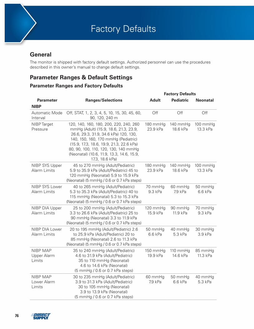
76
Factory Defaults
General The monitor is shipped with factory default settings. Authorized personnel can use the procedures described in this owner’s manual to change default settings.
Parameter Ranges & Default Settings
Parameter Ranges and Factory Defaults
Parameter Ranges/Selections
Factory Defaults
Adult Pediatric Neonatal
NIBP
Automatic Mode Interval
Off, STAT, 1, 2, 3, 4, 5, 10, 15, 30, 45, 60, 90, 120, 240 m
Off Off Off
NIBP Target Pressure
120, 140, 160, 180, 200, 220, 240, 260 mmHg (Adult) (15.9, 18.6, 21.3, 23.9, 26.6, 29.3, 31.9, 34.6 kPa) 120, 130, 140, 150, 160, 170 mmHg (Pediatric) (15.9, 17.3, 18.6, 19.9, 21.3, 22.6 kPa) 80, 90, 100, 110, 120, 130, 140 mmHg (Neonatal) (10.6, 11.9, 13.3, 14.6, 15.9,
17.3, 18.6 kPa)
180 mmHg23.9 kPa
140 mmHg18.6 kPa
100 mmHg13.3 kPa
NIBP SYS Upper Alarm Limits
45 to 270 mmHg (Adult/Pediatric) 5.9 to 35.9 kPa (Adult/Pediatric) 45 to 120 mmHg (Neonatal) 5.9 to 15.9 kPa
(Neonatal) (5 mmHg / 0.6 or 0.7 kPa steps)
180 mmHg23.9 kPa
140 mmHg18.6 kPa
100 mmHg13.3 kPa
NIBP SYS Lower Alarm Limits
40 to 265 mmHg (Adult/Pediatric) 5.3 to 35.3 kPa (Adult/Pediatric) 40 to 115 mmHg (Neonatal) 5.3 to 15.3 kPa
(Neonatal) (5 mmHg / 0.6 or 0.7 kPa steps)
70 mmHg9.3 kPa
60 mmHg7.9 kPa
50 mmHg6.6 kPa
NIBP DIA Upper Alarm Limits
25 to 200 mmHg (Adult/Pediatric) 3.3 to 26.6 kPa (Adult/Pediatric) 25 to 90 mmHg (Neonatal) 3.3 to 11.9 kPa
(Neonatal) (5 mmHg / 0.6 or 0.7 kPa steps)
120 mmHg15.9 kPa
90 mmHg11.9 kPa
70 mmHg9.3 kPa
NIBP DIA Lower Alarm Limits
20 to 195 mmHg (Adult/Pediatric) 2.6 to 25.9 kPa (Adult/Pediatric) 20 to
85 mmHg (Neonatal) 2.6 to 11.3 kPa (Neonatal) (5 mmHg / 0.6 or 0.7 kPa steps)
50 mmHg6.6 kPa
40 mmHg5.3 kPa
30 mmHg3.9 kPa
NIBP MAP Upper Alarm Limits
35 to 240 mmHg (Adult/Pediatric)4.6 to 31.9 kPa (Adult/Pediatric)
35 to 110 mmHg (Neonatal)4.6 to 14.6 kPa (Neonatal)
(5 mmHg / 0.6 or 0.7 kPa steps)
150 mmHg19.9 kPa
110 mmHg14.6 kPa
85 mmHg11.3 kPa
NIBP MAP Lower Alarm Limits
30 to 235 mmHg (Adult/Pediatric)3.9 to 31.3 kPa (Adult/Pediatric)
30 to 105 mmHg (Neonatal)3.9 to 13.9 kPa (Neonatal)
(5 mmHg / 0.6 or 0.7 kPa steps)
60 mmHg7.9 kPa
50 mmHg6.6 kPa
40 mmHg5.3 kPa
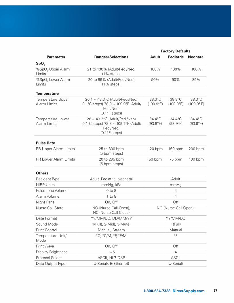
771-800-634-7328 DirectSupply.com
Parameter Ranges/Selections
Factory Defaults
Adult Pediatric Neonatal
SpO2 %SpO2 Upper Alarm Limits
21 to 100% (Adult/Pedi/Neo) (1% steps)
100% 100% 100%
%SpO2 Lower Alarm Limits
20 to 99% (Adult/Pedi/Neo) (1% steps)
90% 90% 85%
Temperature
Temperature Upper Alarm Limits
26.1 ~ 43.3°C (Adult/Pedi/Neo) (0.1ºC steps) 78.9 ~ 109.9°F (Adult/
Pedi/Neo)(0.1°F steps)
38.3°C(100.9°F)
38.3°C(100.9°F)
38.3°C(100.9º F)
Temperature Lower Alarm Limits
26 ~ 43.2°C (Adult/Pedi/Neo) (0.1ºC steps) 78.8 ~ 109.7°F (Adult/
Pedi/Neo)(0.1°F steps)
34.4°C(93.9°F)
34.4°C(93.9°F)
34.4°C(93.9°F)
Pulse Rate PR Upper Alarm Limits 25 to 300 bpm
(5 bpm steps)120 bpm 160 bpm 200 bpm
PR Lower Alarm Limits 20 to 295 bpm (5 bpm steps)
50 bpm 75 bpm 100 bpm
Others
Resident Type Adult, Pediatric, Neonatal Adult
NIBP Units mmHg, kPa mmHg
Pulse Tone Volume 0 to 8 4
Alarm Volume 1 to 8 4
Night Panel On, Off Off
Nurse Call State NO (Nurse Call Open), NC (Nurse Call Close)
NO (Nurse Call Open),
Date Format YY/MM/DD, DD/MM/YY YY/MM/DD
Sound Mode 1(Full), 2(Mid), 3(Mute) 1(Full)
Print Control Manual, Stream Manual
Temperature Unit/Mode
°C, °C/M, °F, °F/M °F
Print Wave On, Off Off
Display Brightness 1~5 4
Protocol Select ASCII, HL7, DSP ASCII
Data Output Type U(Serial), E(Ethernet) U(Serial)
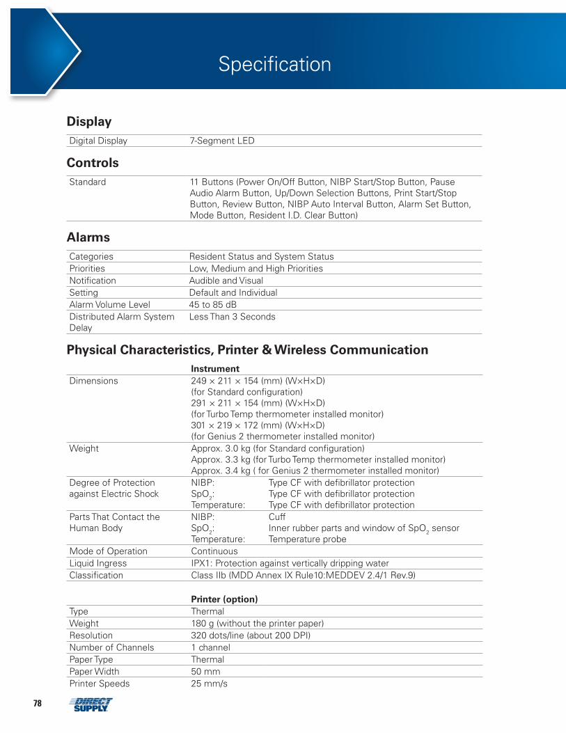
78
Specification
Display Digital Display 7-Segment LED
ControlsStandard 11 Buttons (Power On/Off Button, NIBP Start/Stop Button, Pause
Audio Alarm Button, Up/Down Selection Buttons, Print Start/Stop Button, Review Button, NIBP Auto Interval Button, Alarm Set Button, Mode Button, Resident I.D. Clear Button)
AlarmsCategories Resident Status and System Status Priorities Low, Medium and High Priorities Notification Audible and Visual Setting Default and Individual Alarm Volume Level 45 to 85 dB Distributed Alarm System Delay
Less Than 3 Seconds
Physical Characteristics, Printer & Wireless CommunicationInstrument
Dimensions 249 × 211 × 154 (mm) (W×H×D)(for Standard configuration)291 × 211 × 154 (mm) (W×H×D)(for Turbo Temp thermometer installed monitor)301 × 219 × 172 (mm) (W×H×D)(for Genius 2 thermometer installed monitor)
Weight Approx. 3.0 kg (for Standard configuration)Approx. 3.3 kg (for Turbo Temp thermometer installed monitor)Approx. 3.4 kg ( for Genius 2 thermometer installed monitor)
Degree of Protection against Electric Shock
NIBP: SpO2:Temperature:
Type CF with defibrillator protectionType CF with defibrillator protectionType CF with defibrillator protection
Parts That Contact the Human Body
NIBP: SpO2:Temperature:
Cuff Inner rubber parts and window of SpO2 sensor Temperature probe
Mode of Operation ContinuousLiquid Ingress IPX1: Protection against vertically dripping waterClassification Class IIb (MDD Annex IX Rule10:MEDDEV 2.4/1 Rev.9)
Printer (option)Type Thermal Weight 180 g (without the printer paper) Resolution 320 dots/line (about 200 DPI) Number of Channels 1 channel Paper Type Thermal Paper Width 50 mm Printer Speeds 25 mm/s
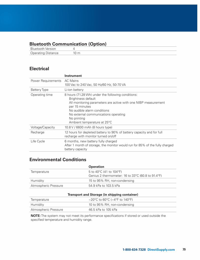
791-800-634-7328 DirectSupply.com
ElectricalInstrument
Power Requirements AC Mains 100 Vac to 240 Vac, 50 Hz/60 Hz, 50-70 VA
Battery Type Li-ion battery
Operating time 8 hours (71.28 Wh) under the following conditions:Brightness defaultAll monitoring parameters are active with one NIBP measurement per 15 minutesNo audible alarm conditionsNo external communications operatingNo printingAmbient temperature at 25°C
Voltage/Capacity 10.8 V / 6600 mAh (8 hours type)
Recharge 12 hours for depleted battery to 90% of battery capacity and for full recharge with monitor turned on/off
Life Cycle 6 months, new battery fully charged After 1 month of storage, the monitor would run for 85% of the fully charged battery capacity
Environmental Conditions Operation
Temperature 5 to 40°C (41 to 104°F) Genius 2 thermometer: 16 to 33°C (60.8 to 91.4°F)
Humidity 15 to 95% RH, non-condensing
Atmospheric Pressure 54.9 kPa to 103.5 kPa
Transport and Storage (in shipping container)
Temperature −20°C to 60°C (−4°F to 140°F)
Humidity 10 to 95% RH, non-condensing
Atmospheric Pressure 46.5 kPa to 105 kPa
NOTE: The system may not meet its performance specifications if stored or used outside the specified temperature and humidity range.
Bluetooth Communication (Option)Bluetooth Version 4Operating Distance 10 m
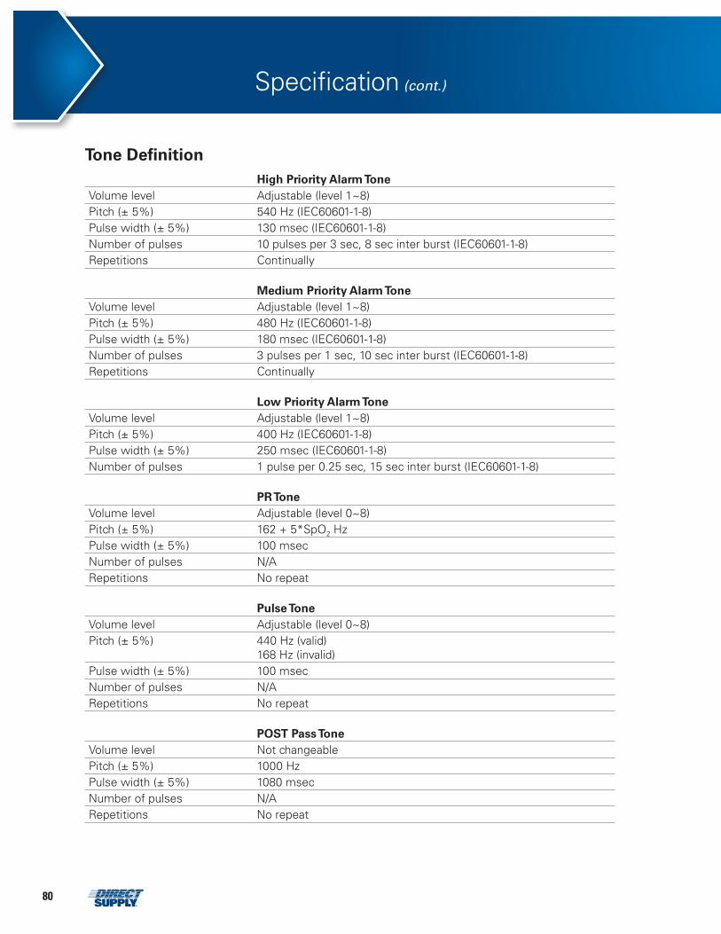
80
Specification (cont.)
Tone DefinitionHigh Priority Alarm Tone
Volume level Adjustable (level 1~8) Pitch (± 5%) 540 Hz (IEC60601-1-8) Pulse width (± 5%) 130 msec (IEC60601-1-8) Number of pulses 10 pulses per 3 sec, 8 sec inter burst (IEC60601-1-8) Repetitions Continually
Medium Priority Alarm ToneVolume level Adjustable (level 1~8) Pitch (± 5%) 480 Hz (IEC60601-1-8) Pulse width (± 5%) 180 msec (IEC60601-1-8) Number of pulses 3 pulses per 1 sec, 10 sec inter burst (IEC60601-1-8) Repetitions Continually
Low Priority Alarm ToneVolume level Adjustable (level 1~8) Pitch (± 5%) 400 Hz (IEC60601-1-8) Pulse width (± 5%) 250 msec (IEC60601-1-8) Number of pulses 1 pulse per 0.25 sec, 15 sec inter burst (IEC60601-1-8)
PR ToneVolume level Adjustable (level 0~8) Pitch (± 5%) 162 + 5*SpO2 Hz Pulse width (± 5%) 100 msec Number of pulses N/A Repetitions No repeat
Pulse ToneVolume level Adjustable (level 0~8) Pitch (± 5%) 440 Hz (valid)
168 Hz (invalid)Pulse width (± 5%) 100 msec Number of pulses N/A Repetitions No repeat
POST Pass ToneVolume level Not changeable Pitch (± 5%) 1000 Hz Pulse width (± 5%) 1080 msec Number of pulses N/A Repetitions No repeat
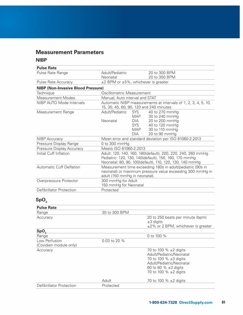
811-800-634-7328 DirectSupply.com
Measurement ParametersNIBP
Pulse Rate Pulse Rate Range Adult/Pediatric
Neonatal20 to 300 BPM 20 to 300 BPM
Pulse Rate Accuracy ±2 BPM or ±5%, whichever is greater
NIBP (Non-Invasive Blood Pressure) Technique Oscillometric Measurement Measurement Modes Manual, Auto interval and STAT NIBP AUTO Mode Intervals Automatic NIBP measurements at intervals of 1, 2, 3, 4, 5, 10,
15, 30, 45, 60, 90, 120 and 240 minutes Measurement Range Adult/Pediatric
Neonatal
SYS MAPDIASYSMAPDIA
40 to 270 mmHg30 to 240 mmHg20 to 200 mmHg 40 to 120 mmHg30 to 110 mmHg20 to 90 mmHg
NIBP Accuracy Mean error and standard deviation per ISO 81060-2:2013 Pressure Display Range 0 to 300 mmHg Pressure Display Accuracy Meets ISO 81060-2:2013 Initial Cuff Inflation Adult: 120, 140, 160, 180(default), 200, 220, 240, 260 mmHg
Pediatric: 120, 130, 140(default), 150, 160, 170 mmHgNeonatal: 80, 90, 100(default), 110, 120, 130, 140 mmHg
Automatic Cuff Deflation Measurement time exceeding 180s in adult/pediatric (90s in neonatal) or maximum pressure value exceeding 300 mmHg in adult (150 mmHg in neonatal).
Overpressure Protector 300 mmHg for Adult 150 mmHg for Neonatal
Defibrillator Protection Protected
SpO2
Pulse Rate Range 30 to 300 BPMAccuracy 20 to 250 beats per minute (bpm)
±3 digits ±2% or 2 BPM, whichever is greater
SpO2 Range 0 to 100 %Low Perfusion (Covidien module only)
0.03 to 20 %
Accuracy
Adult
70 to 100 % ±2 digitsAdult/Pediatric/Neonatal70 to 100 % ±3 digitsAdult/Pediatric/Neonatal60 to 80 % ±3 digits70 to 100 % ±2 digits
70 to 100 % ±2 digitsDefibrillator Protection Protected
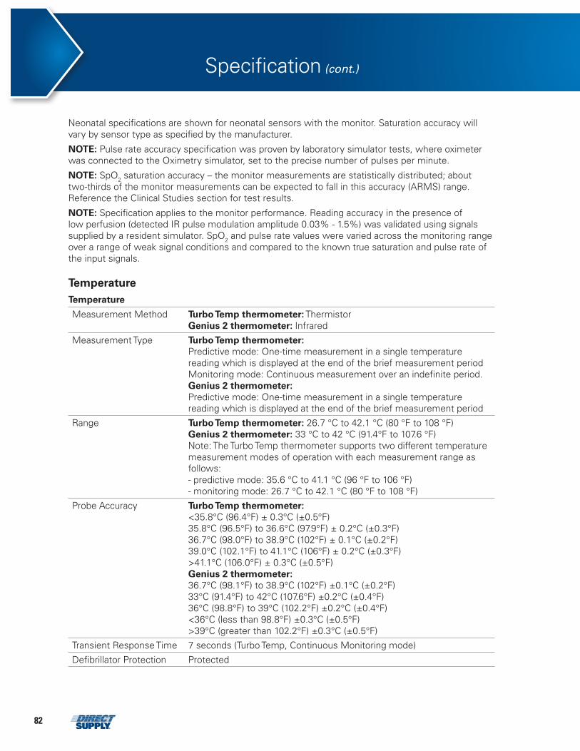
82
Neonatal specifications are shown for neonatal sensors with the monitor. Saturation accuracy will vary by sensor type as specified by the manufacturer.
NOTE: Pulse rate accuracy specification was proven by laboratory simulator tests, where oximeter was connected to the Oximetry simulator, set to the precise number of pulses per minute.
NOTE: SpO2 saturation accuracy – the monitor measurements are statistically distributed; about two-thirds of the monitor measurements can be expected to fall in this accuracy (ARMS) range. Reference the Clinical Studies section for test results.
NOTE: Specification applies to the monitor performance. Reading accuracy in the presence of low perfusion (detected IR pulse modulation amplitude 0.03% - 1.5%) was validated using signals supplied by a resident simulator. SpO2 and pulse rate values were varied across the monitoring range over a range of weak signal conditions and compared to the known true saturation and pulse rate of the input signals.
TemperatureTemperature
Measurement Method Turbo Temp thermometer: Thermistor Genius 2 thermometer: Infrared
Measurement Type Turbo Temp thermometer: Predictive mode: One-time measurement in a single temperature reading which is displayed at the end of the brief measurement periodMonitoring mode: Continuous measurement over an indefinite period.Genius 2 thermometer:Predictive mode: One-time measurement in a single temperature reading which is displayed at the end of the brief measurement period
Range Turbo Temp thermometer: 26.7 °C to 42.1 °C (80 °F to 108 °F)Genius 2 thermometer: 33 °C to 42 °C (91.4°F to 107.6 °F)Note: The Turbo Temp thermometer supports two different temperature measurement modes of operation with each measurement range as follows:- predictive mode: 35.6 °C to 41.1 °C (96 °F to 106 °F)- monitoring mode: 26.7 °C to 42.1 °C (80 °F to 108 °F)
Probe Accuracy Turbo Temp thermometer: <35.8°C (96.4°F) ± 0.3°C (±0.5°F)35.8°C (96.5°F) to 36.6°C (97.9°F) ± 0.2°C (±0.3°F)36.7°C (98.0°F) to 38.9°C (102°F) ± 0.1°C (±0.2°F)39.0°C (102.1°F) to 41.1°C (106°F) ± 0.2°C (±0.3°F)>41.1°C (106.0°F) ± 0.3°C (±0.5°F)Genius 2 thermometer:36.7°C (98.1°F) to 38.9°C (102°F) ±0.1°C (±0.2°F)33°C (91.4°F) to 42°C (107.6°F) ±0.2°C (±0.4°F)36°C (98.8°F) to 39°C (102.2°F) ±0.2°C (±0.4°F)<36°C (less than 98.8°F) ±0.3°C (±0.5°F)>39°C (greater than 102.2°F) ±0.3°C (±0.5°F)
Transient Response Time 7 seconds (Turbo Temp, Continuous Monitoring mode)
Defibrillator Protection Protected
Specification (cont.)
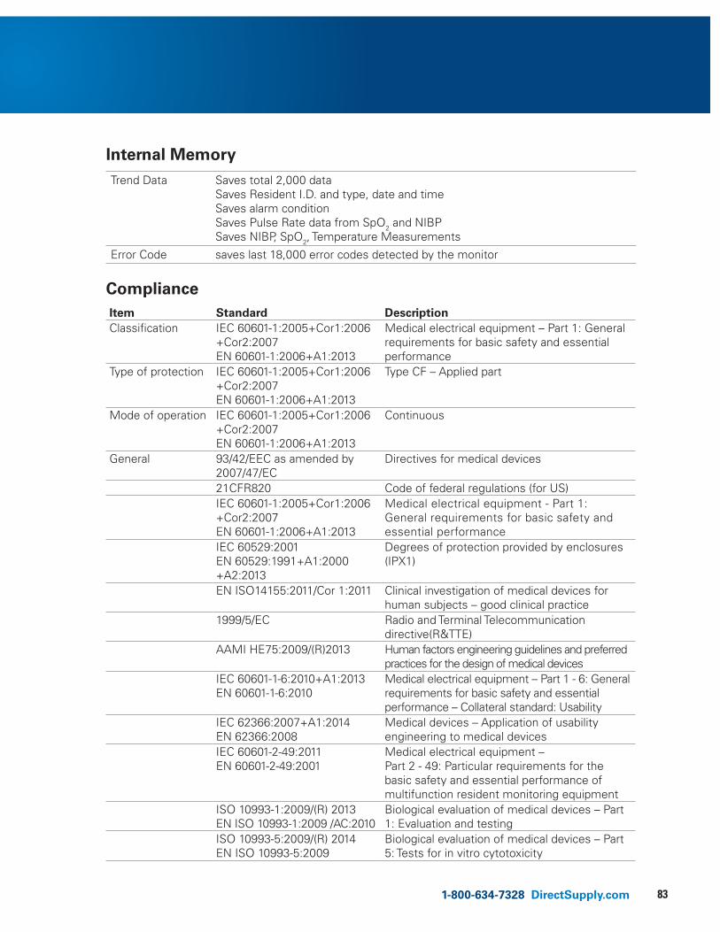
831-800-634-7328 DirectSupply.com
Internal MemoryTrend Data Saves total 2,000 data
Saves Resident I.D. and type, date and timeSaves alarm conditionSaves Pulse Rate data from SpO2 and NIBPSaves NIBP, SpO2, Temperature Measurements
Error Code saves last 18,000 error codes detected by the monitor
ComplianceItem Standard DescriptionClassification IEC 60601-1:2005+Cor1:2006
+Cor2:2007 EN 60601-1:2006+A1:2013
Medical electrical equipment – Part 1: General requirements for basic safety and essential performance
Type of protection IEC 60601-1:2005+Cor1:2006+Cor2:2007 EN 60601-1:2006+A1:2013
Type CF – Applied part
Mode of operation IEC 60601-1:2005+Cor1:2006+Cor2:2007 EN 60601-1:2006+A1:2013
Continuous
General 93/42/EEC as amended by 2007/47/EC
Directives for medical devices
21CFR820 Code of federal regulations (for US) IEC 60601-1:2005+Cor1:2006+Cor2:2007EN 60601-1:2006+A1:2013
Medical electrical equipment - Part 1: General requirements for basic safety and essential performance
IEC 60529:2001EN 60529:1991+A1:2000+A2:2013
Degrees of protection provided by enclosures (IPX1)
EN ISO14155:2011/Cor 1:2011 Clinical investigation of medical devices for human subjects – good clinical practice
1999/5/EC Radio and Terminal Telecommunication directive(R&TTE)
AAMI HE75:2009/(R)2013 Human factors engineering guidelines and preferred practices for the design of medical devices
IEC 60601-1-6:2010+A1:2013EN 60601-1-6:2010
Medical electrical equipment – Part 1 - 6: General requirements for basic safety and essential performance – Collateral standard: Usability
IEC 62366:2007+A1:2014EN 62366:2008
Medical devices – Application of usability engineering to medical devices
IEC 60601-2-49:2011EN 60601-2-49:2001
Medical electrical equipment –Part 2 - 49: Particular requirements for the basic safety and essential performance of multifunction resident monitoring equipment
ISO 10993-1:2009/(R) 2013EN ISO 10993-1:2009 /AC:2010
Biological evaluation of medical devices – Part 1: Evaluation and testing
ISO 10993-5:2009/(R) 2014EN ISO 10993-5:2009
Biological evaluation of medical devices – Part 5: Tests for in vitro cytotoxicity
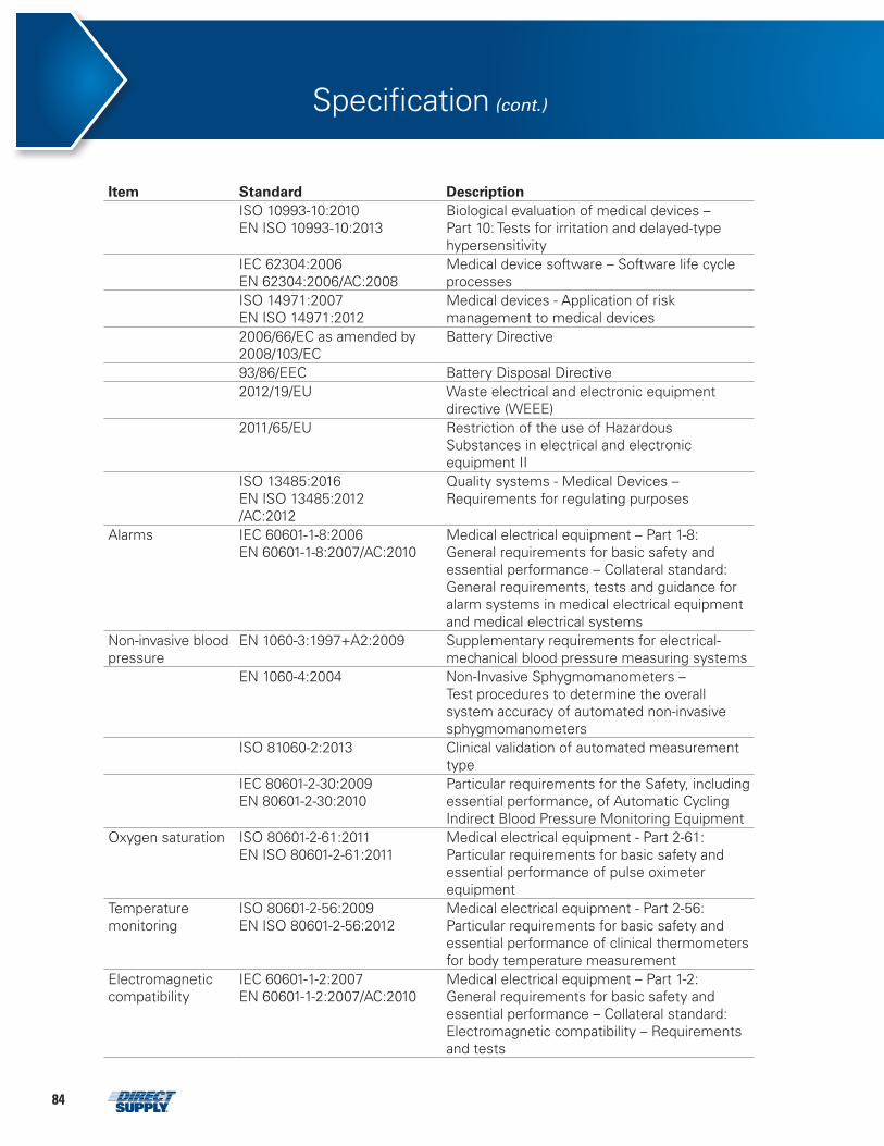
84
Item Standard DescriptionISO 10993-10:2010EN ISO 10993-10:2013
Biological evaluation of medical devices – Part 10: Tests for irritation and delayed-type hypersensitivity
IEC 62304:2006EN 62304:2006/AC:2008
Medical device software – Software life cycle processes
ISO 14971:2007EN ISO 14971:2012
Medical devices - Application of risk management to medical devices
2006/66/EC as amended by 2008/103/EC
Battery Directive
93/86/EEC Battery Disposal Directive 2012/19/EU Waste electrical and electronic equipment
directive (WEEE)2011/65/EU Restriction of the use of Hazardous
Substances in electrical and electronic equipment II
ISO 13485:2016EN ISO 13485:2012/AC:2012
Quality systems - Medical Devices – Requirements for regulating purposes
Alarms IEC 60601-1-8:2006 EN 60601-1-8:2007/AC:2010
Medical electrical equipment – Part 1-8: General requirements for basic safety and essential performance – Collateral standard: General requirements, tests and guidance for alarm systems in medical electrical equipment and medical electrical systems
Non-invasive blood pressure
EN 1060-3:1997+A2:2009 Supplementary requirements for electrical-mechanical blood pressure measuring systems
EN 1060-4:2004 Non-Invasive Sphygmomanometers – Test procedures to determine the overall system accuracy of automated non-invasive sphygmomanometers
ISO 81060-2:2013 Clinical validation of automated measurement type
IEC 80601-2-30:2009EN 80601-2-30:2010
Particular requirements for the Safety, including essential performance, of Automatic Cycling Indirect Blood Pressure Monitoring Equipment
Oxygen saturation ISO 80601-2-61:2011 EN ISO 80601-2-61:2011
Medical electrical equipment - Part 2-61: Particular requirements for basic safety and essential performance of pulse oximeter equipment
Temperature monitoring
ISO 80601-2-56:2009EN ISO 80601-2-56:2012
Medical electrical equipment - Part 2-56: Particular requirements for basic safety and essential performance of clinical thermometers for body temperature measurement
Electromagnetic compatibility
IEC 60601-1-2:2007 EN 60601-1-2:2007/AC:2010
Medical electrical equipment – Part 1-2: General requirements for basic safety and essential performance – Collateral standard: Electromagnetic compatibility – Requirements and tests
Specification (cont.)
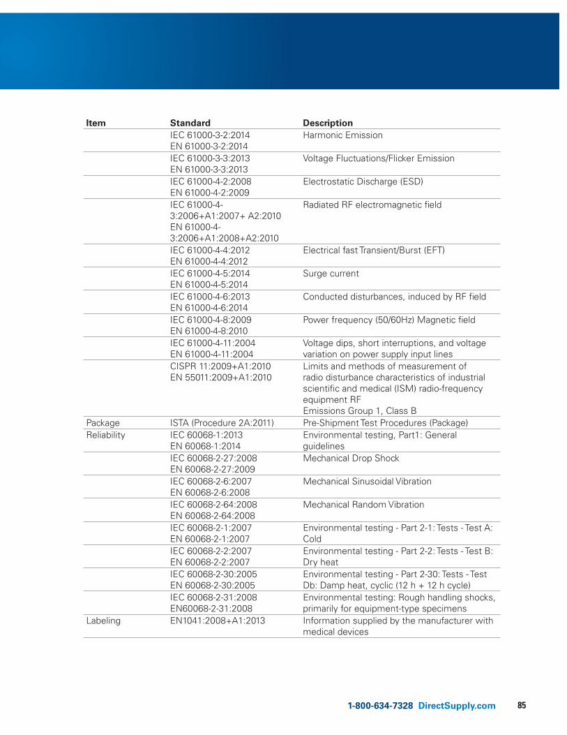
851-800-634-7328 DirectSupply.com
Item Standard DescriptionIEC 61000-3-2:2014EN 61000-3-2:2014
Harmonic Emission
IEC 61000-3-3:2013EN 61000-3-3:2013
Voltage Fluctuations/Flicker Emission
IEC 61000-4-2:2008EN 61000-4-2:2009
Electrostatic Discharge (ESD)
IEC 61000-4-3:2006+A1:2007+ A2:2010 EN 61000-4-3:2006+A1:2008+A2:2010
Radiated RF electromagnetic field
IEC 61000-4-4:2012EN 61000-4-4:2012
Electrical fast Transient/Burst (EFT)
IEC 61000-4-5:2014EN 61000-4-5:2014
Surge current
IEC 61000-4-6:2013EN 61000-4-6:2014
Conducted disturbances, induced by RF field
IEC 61000-4-8:2009EN 61000-4-8:2010
Power frequency (50/60Hz) Magnetic field
IEC 61000-4-11:2004EN 61000-4-11:2004
Voltage dips, short interruptions, and voltage variation on power supply input lines
CISPR 11:2009+A1:2010EN 55011:2009+A1:2010
Limits and methods of measurement of radio disturbance characteristics of industrial scientific and medical (ISM) radio-frequency equipment RF Emissions Group 1, Class B
Package ISTA (Procedure 2A:2011) Pre-Shipment Test Procedures (Package)Reliability IEC 60068-1:2013
EN 60068-1:2014Environmental testing, Part1: General guidelines
IEC 60068-2-27:2008EN 60068-2-27:2009
Mechanical Drop Shock
IEC 60068-2-6:2007EN 60068-2-6:2008
Mechanical Sinusoidal Vibration
IEC 60068-2-64:2008EN 60068-2-64:2008
Mechanical Random Vibration
IEC 60068-2-1:2007EN 60068-2-1:2007
Environmental testing - Part 2-1: Tests - Test A: Cold
IEC 60068-2-2:2007EN 60068-2-2:2007
Environmental testing - Part 2-2: Tests - Test B: Dry heat
IEC 60068-2-30:2005EN 60068-2-30:2005
Environmental testing - Part 2-30: Tests - Test Db: Damp heat, cyclic (12 h + 12 h cycle)
IEC 60068-2-31:2008EN60068-2-31:2008
Environmental testing: Rough handling shocks, primarily for equipment-type specimens
Labeling EN1041:2008+A1:2013 Information supplied by the manufacturer with medical devices
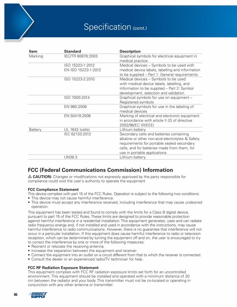
86
Item Standard DescriptionMarking IEC/TR 60878:2003 Graphical symbols for electrical equipment in
medical practiceISO 15223-1:2012EN ISO 15223-1:2012
Medical devices – Symbols to be used with medical device labels, labelling and information to be supplied – Part 1: General requirements
ISO 15223-2:2010 Medical devices – Symbols to be used with medical device labels, labelling, and information to be supplied – Part 2: Symbol development, selection and validation
ISO 7000:2014 Graphical symbols for use on equipment – Registered symbols
EN 980:2008 Graphical symbols for use in the labeling of medical devices
EN 50419:2006 Marking of electrical and electronic equipment in accordance with article II (2) of directive 2002/96/EC (WEEE)
Battery UL 1642 (cells) Lithium batteryIEC 62133:2012 Secondary cells and batteries containing
alkaline or other non-acid electrolytes & Safety requirements for portable sealed secondary cells, and for batteries made from them, for use in portable applications
UN38.3 Lithium battery
Specification (cont.)
FCC (Federal Communications Commission) Information• CAUTION: Changes or modifications not expressly approved by the party responsible for compliance could void the user’s authority to operate the equipment
FCC Compliance StatementThis device complies with part 15 of the FCC Rules. Operation is subject to the following two conditions:• This device may not cause harmful interference.• This device must accept any interference received, including interference that may cause undesired
operation.This equipment has been tested and found to comply with the limits for a Class B digital device, pursuant to part 15 of the FCC Rules. These limits are designed to provide reasonable protection against harmful interference in a residential installation. This equipment generates, uses and can radiate radio frequency energy and, if not installed and used in accordance with the instructions, may cause harmful interference to radio communications. However, there is no guarantee that interference will not occur in a particular installation. If this equipment does cause harmful interference to radio or television reception, which can be determined by turning the equipment off and on, the user is encouraged to try to correct the interference by one or more of the following measures:• Reorient or relocate the receiving antenna.• Increase the separation between the equipment and receiver.• Connect the equipment into an outlet on a circuit different from that to which the receiver is connected.• Consult the dealer or an experienced radio/TV technician for help.
FCC RF Radiation Exposure StatementThis equipment complies with FCC RF radiation exposure limits set forth for an uncontrolled environment. This equipment should be installed and operated with a minimum distance of 20 cm between the radiator and your body. This transmitter must not be co-located or operating in conjunction with any other antenna or transmitter.
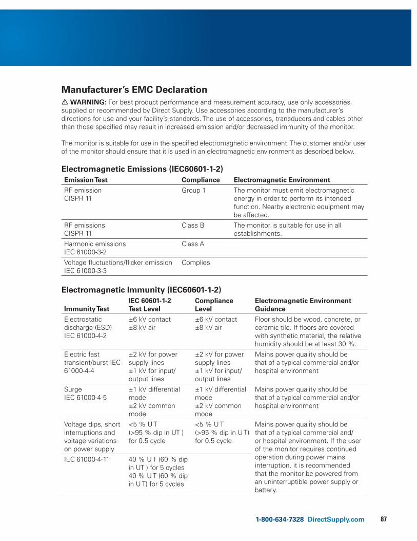
871-800-634-7328 DirectSupply.com
Manufacturer’s EMC Declaration• WARNING: For best product performance and measurement accuracy, use only accessories supplied or recommended by Direct Supply. Use accessories according to the manufacturer’s directions for use and your facility’s standards. The use of accessories, transducers and cables other than those specified may result in increased emission and/or decreased immunity of the monitor.
The monitor is suitable for use in the specified electromagnetic environment. The customer and/or user of the monitor should ensure that it is used in an electromagnetic environment as described below.
Electromagnetic Emissions (IEC60601-1-2)Emission Test Compliance Electromagnetic Environment
RF emission CISPR 11
Group 1 The monitor must emit electromagnetic energy in order to perform its intended function. Nearby electronic equipment may be affected.
RF emissions CISPR 11
Class B The monitor is suitable for use in all establishments.
Harmonic emissions IEC 61000-3-2
Class A
Voltage fluctuations/flicker emission IEC 61000-3-3
Complies
Electromagnetic Immunity (IEC60601-1-2)
Immunity Test IEC 60601-1-2 Test Level
Compliance Level
Electromagnetic Environment Guidance
Electrostatic discharge (ESD) IEC 61000-4-2
±6 kV contact±8 kV air
±6 kV contact±8 kV air
Floor should be wood, concrete, or ceramic tile. If floors are covered with synthetic material, the relative humidity should be at least 30 %.
Electric fast transient/burst IEC 61000-4-4
±2 kV for power supply lines±1 kV for input/output lines
±2 kV for power supply lines ±1 kV for input/output lines
Mains power quality should be that of a typical commercial and/or hospital environment
Surge IEC 61000-4-5
±1 kV differential mode±2 kV common mode
±1 kV differential mode±2 kV common mode
Mains power quality should be that of a typical commercial and/or hospital environment
Voltage dips, short interruptions and voltage variations on power supply
<5 % U T (>95 % dip in UT ) for 0.5 cycle
<5 % U T(>95 % dip in U T) for 0.5 cycle
Mains power quality should be that of a typical commercial and/or hospital environment. If the user of the monitor requires continued operation during power mains interruption, it is recommended that the monitor be powered from an uninterruptible power supply or battery.
IEC 61000-4-11 40 % U T (60 % dip in UT ) for 5 cycles40 % U T (60 % dip in U T) for 5 cycles
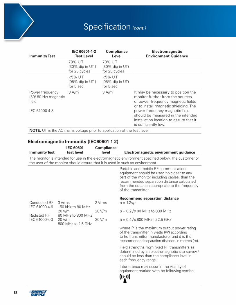
88
Immunity Test IEC 60601-1-2
Test Level Compliance
Level Electromagnetic
Environment Guidance
70% U T(30% dip in UT ) for 25 cycles
70% U T(30% dip in UT) for 25 cycles
<5% U T(95% dip in UT ) for 5 sec.
<5% U T(95% dip in UT) for 5 sec.
Power frequency (50/ 60 Hz) magnetic field
IEC 61000-4-8
3 A/m 3 A/m It may be necessary to position the monitor further from the sources of power frequency magnetic fields or to install magnetic shielding. The power frequency magnetic field should be measured in the intended installation location to assure that it is sufficiently low.
NOTE: UT is the AC mains voltage prior to application of the test level.
Electromagnetic Immunity (IEC60601-1-2)
Immunity Test IEC 60601 test level
Compliancelevel Electromagnetic environment guidance
The monitor is intended for use in the electromagnetic environment specified below. The customer or the user of the monitor should assure that it is used in such an environment.
Conducted RF IEC 61000-4-6
Radiated RFIEC 61000-4-3
3 Vrms150 kHz to 80 MHz20 V/m80 MHz to 800 MHz20 V/m800 MHz to 2.5 GHz
3 Vrms
20 V/m
20 V/m
Portable and mobile RF communications equipment should be used no closer to any part of the monitor including cables, than the recommended separation distance calculated from the equation appropriate to the frequency of the transmitter.
Recommend separation distanced = 1.2√p
d = 0.2√p 80 MHz to 800 MHz
d = 0.4√p 800 MHz to 2.5 GHz
where P is the maximum output power rating of the transmitter in watts (W) according to he transmitter manufacturer and d is the recommended separation distance in metres (m).
Field strengths from fixed RF transmitters as deter-mined by an electromagnetic site survey,a should be less than the compliance level in each frequency range.b
Interference may occur in the vicinity of equipment marked with he following symbol:
Specification (cont.)
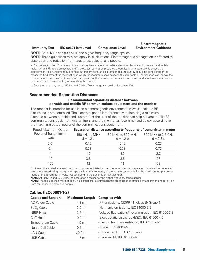
891-800-634-7328 DirectSupply.com
Immunity Test IEC 60601 Test Level Compliance LevelElectromagnetic
Environment Guidance
NOTE: At 80 MHz and 800 MHz, the higher frequency range applies. NOTE: These guidelines may not apply in all situations. Electromagnetic propagation is affected by absorption and reflection from structures, objects, and people.a. Field strengths from fixed transmitters, such as base stations for radio (cellular/cordless) telephones and land mobile radio, AM and FM radio broadcast, and TV broadcast cannot be predicted theoretically with accuracy. To assess the electromagnetic environment due to fixed RF transmitters, an electromagnetic site survey should be considered. If the measured field strength in the location in which the monitor is used exceeds the applicable RF compliance level above, the monitor should be observed to verify normal operation. If abnormal performance is observed, additional measures may be necessary, such as re-orienting or relocating the monitor.
b. Over the frequency range 150 kHz to 80 MHz, field strengths should be less than 3 V/m
Recommended Separation DistancesRecommended separation distance between
portable and mobile RF communications equipment and the monitor
The monitor is intended for use in an electromagnetic environment in which radiated RF disturbances are controlled. The electromagnetic interference by maintaining a minimum distance between portable and customer or the user of the monitor can help prevent mobile RF communications equipment (transmitters) and the monitor as recommended below, according to the maximum output power of the communications equipment.
Rated Maximum Output Power of Transmitter in
watt
Separation distance according to frequency of transmitter in meter
150 kHz to MHzd = 1.2 p
80 MHz to 800 MHzd = 1.2 p
800 MHz to 2.5 GHz d = 2.3 p
0.01 0.12 0.12 0.23
0.1 0.38 0.38 0.73
1 1.2 1.2 2.3
10 3.8 3.8 7.3
100 12 12 23For transmitters rated at a maximum output power not listed above, the recommended separation distance d in meters (m) can be estimated using the equation applicable to the frequency of the transmitter, where P is the maximum output power rating of the transmitter in watts (W) according to the transmitter manufacturer.NOTE: At 80 MHz and 800 MHz, the separation distance for the higher frequency range appliesNOTE: These guidelines may not apply in all situations. Electromagnetic propagation is affected by absorption and reflection from structures, objects, and people.
Cables (IEC60601-1-2)Cables and Sensors Maximum Length Complies with
AC Power Cable 1.8 m -RF emissions, CISPR 11, Class B/ Group 1-Harmonic emissions, IEC 61000-3-2-Voltage fluctuations/flicker emission, IEC 61000-3-3-Electrostatic discharge (ESD), IEC 61000-4-2-Electric fast transient/burst, IEC 61000-4-4-Surge, IEC 61000-4-5-Conducted RF, IEC 61000-4-6-Radiated RF, IEC 61000-4-3
SpO2 Cable 3.2 m
NIBP Hose 2.5 m
Cuff Hose 0.2 m
Temperature Cable 1.0 m
Nurse Call Cable 0.1 m
LAN Cable 20.0 m
USB Cable 1.5 m
90
Limited Warranty
We offer to you, as the original purchaser, a warranty for the Attendant® Connected Vital Signs Monitor. Our warranty applies for the limited warranty period stated below. If any device or device part listed below is defective in material or workmanship during the applicable limited warranty period, we will repair or replace it at our cost. Please note that the decision to repair or replace a device or device part will be at our discretion. Our warranty applies only if the device is properly maintained by the original purchaser for normal, indoor use and does not cover normal wear and tear, modification of the device, or damage caused by abuse, improper use, failure to maintain, use which exceeds the published device limitations or the combination of any device with another product. In addition, our warranty does not cover fading, colorfastness, stains, spills or exposure to chemicals, odors, heat or light. In certain cases, we may provide you repair or adjustment instructions and/or replacement parts and ask you to perform a repair or adjustment or replace a defective part.
Our warranty gives you specific legal rights, and you may also have other rights, which vary from state to state. Please note that our limited warranty period begins when we ship the device to you. The limited warranty period and our obligations under the warranty end once you transfer the device to someone else, or at the end of the applicable limited warranty period identified below, whichever is earlier.
Warranty (Parts)Anticipated Usable
Device Life
Attendant Connected Vital Signs Monitor
2 years on device 6 months on accessories
2 years on device 6 months on accessories
Anticipated Usable Device Life is based on normal use with proper maintenance, cleaning and storage. You should still inspect, monitor and care for the device as described in this guide, as the device may need to be replaced sooner than anticipated in particular situations.
DIRECT SUPPLY MANUFACTURING, INC. MAKES NO IMPLIED WARRANTIES OF MERCHANTABILITY OR FITNESS FOR A PARTICULAR PURPOSE; THESE AND ALL OTHER IMPLIED WARRANTIES ARE SPECIFICALLY DISCLAIMED. TO THE FULLEST EXTENT ALLOWED BY LAW, DIRECT SUPPLY MANUFACTURING, INC. WILL NOT BE LIABLE FOR ANY INCIDENTAL, SPECIAL, CONSEQUENTIAL OR PUNITIVE DAMAGES, OR LOST PROFITS THAT MAY RESULT FROM THE DEVICE OR YOUR USE OR INABILITY TO USE THE DEVICE EVEN IF ADVISED OF THE POSSIBILITY OF SUCH DAMAGES. OUR TOTAL LIABILITY TO YOU, IF ANY, IS LIMITED TO THE PRICE OF THE PRODUCT OR SERVICE GIVING RISE TO YOUR CLAIM. Some states do not allow an exclusion or limitation of incidental or consequential damages, or how long an implied warranty lasts, so the above limitations or exclusions may not apply to you. If implied warranties are not excluded, and to the extent allowed by law, we limit any and all implied warranties to the applicable warranty period identified above. Except for rights under any applicable state law, the remedies provided under this warranty are your sole and exclusive remedy for any breach of our warranty and state the entire limit of our responsibilities.

911-800-634-7328 DirectSupply.com
Our promise to you is that you will have a convenient and easy ordering experience, receive a quality Attendant Connected Vital Signs Monitor, and enjoy outrageous customer service. If you have any questions about the Attendant Connected Vital Signs Monitor you have purchased or would like to request warranty service, please contact Direct Supply Equipment & Furnishings at 1-800-634-7328, 6767 North Industrial Road, Milwaukee, WI 53223, [email protected].
Customer Service

Distributed by Direct Supply Manufacturing, Inc. 6635 N Industrial Road, Milwaukee WI 53223.
© 2018 Direct Supply Manufacturing, Inc. All Rights Reserved. Direct Supply®, Attendant®, and all associated logos are the registered trademarks of Direct Supply Inc., used under license
11638Date of Printing: August 2018A7574-2