Embed Size (px)
Citation preview

A
ATTACHMENT 2
AND TRIENNIAL FIRE PROTECTION INSPECTIONPhase 2 Significance Determination
FIRE PROTECTION REGULATIONS
10 CFR 50.48, Fire protection.
- ---- !(b) --Appendix R-to this-part establishes-fire protection features'required to satisfy Crit 3of Appendix A to this part with respect to certain generic issues for nuclear power plantslicensed to operate before January 1, 1979.... With respect to all other fire protectionfeatures covered by Appendix R, all nuclear power plants licensed to operate beforeJanuary 1, 1979, must satisfy the applicable requirements of Appendix R to this Dart,including specifically the requirements of Sections ll, III1 1i, 1nd Ill 0."
10 CFR Part 50, Appendix R, Paragraph Ill.G, Fire protection of safe shutdown capability.
"2. Except as provided for in paragraph G.3 of this section, where cables or equipment,including associated non-safety circuits that could prevent operation or causemaloperation due to hot shorts, open circuits, or shorts to ground, of redundant trains ofsystems necessaryto achieve and maintain hot shutdown conditions are locatedwithinthesame-fire area outside of primary containment, one of the following means of - -
ensuring that one of the redundant trains Is free of fire damage shall be provided:.
"a. Separation of cables and equipment and associated non-safety circuits ofredundant trains by a fire barrier having a 3-hour rating. Structural steel forming apart of or supporting such fire barriers shall be protected to provide fire resistanceequivalent to that required of the barrier;
"b. Separation of cables and equipment and associated non-safety circuits ofredundant trains by a horizontal distance of more than 20 feet with no interveningcombustible or fire hazards. In addition, fire detectors and an automatic firesuppression system shall be installed in the fire area; or
"c. Enclosure of cable and equipment and associated non-safety circuits of oneredundant train in a fire barrier having a 1-hour rating, In addition, fire detectorsand an automatic fire suppression system shall be installed in the fire area;"
FINDING
In Fire Zones 98J (diesel generator corridor) and 99M (north switchgear room - green train), thelicensee failed to ensure that cables or equipment of redundant trains of systems necessary toachieve and maintain hot shutdown conditions (including associated non-safety circuits that
information in this record was deleted 25in accordance ith the Freedom of nInomailo5
Act, exemtoptionFOIA

I
could prevent operation or cause maloperation due to hot shorts, open circuits, or shorts toground) was free of fire damage. This is a violation of 10 CFR Part 50, Appendix R,Section III.G.2.
As discussed in the inspection report, the following were located in Fire Zone 98J. This list is aresult of sampling by the team and is not all-inclusive.'
* Cables associated with emergency diesel generators (EDGs)
* Cables associated with EDG lockout relays
* Cables associated with EDG output breakers
* Cables associated with service water (SW) to EDG jacket water cooler valves, CV 3806and CV 3807
* Cables associated with emergency feedwqter (EFW) pumps P7A and P7B.
* Cables associated with numerous EFW valves
* Cables associated with EFW pump P76 suction valves, CV2800, 2803, and 3850
* Turbine-driven EFW pump steam supply valves
* . Cables associated with makeup pumpsP36A, B and C .
ewhCables associated with stefm generator atmospheric dump and block valves for bothsteam generators (CV 2668, 2676, CV-2618, and 2619)
*eiWCables associated withaCV-c3643 (SWdischarge to auxiliary cooling water)
* Cables associated with pressurizer emergency relief valves and emergency relief blockvalves, PSV-1000 and CV-1000
* Cables associated with SW pumps, P4A, P41, and P4C
As discussed in the the inspection report, the following were located in Fire Zone 99M. This listis a result of sampling by the team and is not all-inclusive.
* Cables associated with SW pumps, P4A. P4B, and P4C
* Cables associated with EDG 4KA and EDG 4KB output breakers
* Cables associated with EFW pumps P7A and P76
* Cables associated with both trains of EFW flow valves
26
I .
* Cables associated with EFW pump P7B suction valves, CV2800, 2803, and 3850
* Cables associated with makeup pumps P36A, P36B, and P36C
* Output breaker for EDG 4KB
On August 28, 2001, at the region's request, the licensee sent a more comprehensivecomponent and cable listing for Fire Zones 98J and 99M that included expanded componentdescriptions. This component list is provided as Attachment 3 to the TIA memorandum.
CREDIT FOR MANUAL ACTIONS
Tfihecen-se chose NOT to protect any cables associated with redundant equipment necessaryfor achieving and maintaining hot shutdown conditions. Rather, they credit manual actions forrestoring equipment whose power and/or control cables could be damaged by a fire. Therefore,in the Phase 2 SDP, most automatic functions were not available.
The region considered credit for manually restoring each function individually. We did notconsider the synergistic impact of the numerous manual actions required to restore numerousfunctions. There are many manual actions that may be required in this fire area and the licenseedid not implement a single procedure for coordinating these actions. In addition, the licensee didnot provide any information to the operators concerning which of these numerous manualactions are time critical. In a telephone conference, Gareth Parry (NRR), expressed doubt thatthe licensee could successfully' perform this number of manual actions required-for restoring allsafe shutdown functions, given a fire in Fire Zone-98J. -During this telephone conferen e,-we'did.not discuss Fire Zone 99M. -
SUMMARY
Fire Zone 98J: -.-*vl.
Fire Zone 99M: ih _
In reviewing the results of each sequence, it can be concluded that the significance.is drivenmostly by the fact that no credit was ienfor restoration of EFW. This function appears in all ofthe sequences that resulted in significance. However, if a credit of 1 was given forr ction lpoUld b d hould be
ty the coun ing rule, he numb ,,would '
still result in these findinigs having a risk significance o .' a
Troy Pruett, the Region IV senior reactor analyst, performed a lower bounding analysis on bothof these fire zones, by lowering the ignition frequency of both fire zones by a factor of 100 andgiving additional credit for restoration of some functions. The lower bounding analysis for Fire
27
'A
Zone 98J, with credit for restoration of EFW and FB, resulted in white. The lower boundimyanalysis for Fire Zone 99M, with credit for restoration of EFW and PCS, also resulted irk
28

i
SDP - FIRE ZONE 98J
CREDIBLE FIRE SCENARIO - performed by N. IQBAL of NRR
* Ignition Sources: Emergency chiller chilled water pump approx I gal. of lube oilSwgr room emergency chillerBattery charger room a/c unitN. battery room/Charger room unit coolerS. battery room/Charger room unit coolerElectrical wall-mounted cabinets125V dc distribution-pa nelslInstrumentation cabinets
Combustibles: Cable insulation (cables not IEEE-383)Lube oilTransient combustibles (55 gal EDG lube oil barrels not prohibitedduring operation)
a Fire Modeling Results - Emergency Chiller Chilled Water Pump Lube Oil Spill
Diesel generator access corridor - 98JThe dimensions were from drawings; however, are very close to the acutal dimensionsWidth = 8 ft, Length = 50 ft, Height = 12 ftVent Opening - Width = 3 ft, Height =2 ftHeight of Cable Tray from floor = 6 ft
Pool Fire Pool Fire Heat Pool Fire Flame Pool Fire Access CorridorDiameter Release Rate Flame Impingement Buming Hot Gas Layer .Temperature
D Height to Duration (*F)(ft) (kW) HI Cable tray 11n)
Ut) ~~~(min) _ _ _ _ _ _
m in2 3 min 4 min
1 131 4.5 No 17 203 218 228 2361.5 295 6 Yes 7.5 293 320 337 3502 524 7.5 Yes 4.3 394 433 458 477
2.5 818 9 Yes 2.7 504 556 5903 1178 10 Yes 1.9 621 688 -
Note:
The above calculations are based on the principles developed in the Society of Fire Protection Engineers (SFPE) Handbook of FireProtection Engineering, 2 nd Edition. Calculations are based on certain assumptions and has Inherent limitations. The results ofsuch calculations may or may not have reasonable predictive capabilities for a given situation, and should only be Interpreted by anInformed user.
FIRE SCENARIO
Fire Zone 98J consists of the diesel generator corridor, the north charger room (Room 98), and
29

the electrical equipment room (Room 111). Room 111 is separated from Room 98 by anunrated wall and door. The north charger room is basically a small room off of the dieselcorridor with an approximate 6 foot high x 4 foot wide opening to the corridor that has a headerthat extends approximately 3 - 4 feet from the ceiling. We assumed a fire started in theemergency chiller chilled water pump, and developed a hot gas layer that did not involve eitherthe north charger room or Room 111. We chose the diesel corridor as the worst case, becauseof the large amount of redundant cables in the. room, which were not protected against firedamage. The diesel corridor contains mostly green train cables, but has a number of red trainpower and control cables which are not protected from fire damage.
The diesel generator corridor has a pre-action suppression system which actuates via across-zoned detection system, consisting of c i -mounted smoIke etectors-and temperature . -
-- detctrs (wire) installed on the top of the cables in each cable tray. The suppression systemwill not actually provide water to the sprinkler heads until the suppression control system hasreceived a signal from a ceiling-mounted smoke detector plus a signal from a detector wire. Fora floor-based fire, a hot gas layer could develop causing the ceiling-mounted detector to send asignal to the suppression control system. Sprinkler heads would also begin opening.However, because the detector wires are on top of the cables in the cables trays, there could besignificant damage to cables below the detector wires before they provide a signal to thesuppression control system. This suppression/detection configuration was discussed with MarkSalley (NRR) who agreed that the suppression system should not be considered in a normaloperating state, and suggested the sprinkler system be considered in a state of highdegradation. Region IV assumed moderate degradation, because of uncertainty in the amountof cable damage which could occur before activiation of the suppression system in Fire Zone98J. -.
,Automatic suppression is not provided in Room 111; however, because there were moreredundant cables in the diesel corridor-we did not postulate a fire in this room. We did not
* Consider damage to equipment and cables in this room from a fire in the diesel generatorcorridor; likewise we did not consider damage to cables and equipment in the diesel generatorcorridor from a fire in Room 111. We based this decision on the fact that a non-rated concreteblock wall ahd non-rated steel door was installed between the two rooms.
Automatic suppression is not provided in the battery charger room. This room is open to thediesel gnerator corridor; however, the opening has a 3-4 foot header extending verticallydownward from the ceiling which would inhibit the spread of the hot gas layer into or out of thisroom. Therefore, we did not consider a fire in the diesel generator corridor damaging equipmentand cables in this room, nor did we consider a fire in this room damaging equipment and cablesin the diesel generator corridor.
FMF CALCULATION (from MC 0609, App F)
IGNITION FREQUENCY: IF = 1.63 x 10 Q from IPEEE (Log IF = -2.79)
The IF for this fire zone In the IPEEE is either 4.11 E-3 (for P76 EFW not failed) or 2.9E-4 (for P7B failed). An attachmentto the IPEEE provided after the Inspection showed some component-level IFs; however, no IF for the component weassumed to cause the fire was provided. We noted that sum of the IFs for the components In the attachment (2.59E-3)did not agree with the total IF for the fire zone provided in the IPEEE (4.1 1E-3). We also noted that the revision numbers
30

on the IPEEE and the attachment did not agree. In the light of this uncertainty, we used the IF for the fire zone from theIPEEE (4.1 1E-3) and subtracted the IF for the electrical cabinets (2.24E-3), the IF for the battery charger (2.11 E-4), andthe IF for welding wlfire watch (2.67E.5). The resulting IF = 1.63E.3.
1-HOUR RATED FIRE BARRIER: Assumed high degradation (FB = 0)
MANUAL SUPPRESSION: Assumed no degradation (MS = -1)
AUTOMATIC DETECTIONISUPPRESSION: Assumed moderate degradation (AS = -.75)
COMMON CAUSE/DEPENDENCIES: Thl 5.3: Assumed shared FP sprinkler and fire hoseheader/source (CC = +0.25)
FMF =LoglF+FB+MS+AS +CC- 2.79 + 0 -1.0 - .75 + 0.25
= -4.29
EXPOSURE TIME: Table 5.5: greater than 30 days = Row E*
*Note: If AS is assumed to be highly degraded, the FMF would be -3.54 and wewould be in Row D.
-. .. e .. .
31

.
ANO, UNIT I SDP WORKSHEETSFire Zone 98J (Diesel Generator Corridor)
Tbl 3.2 - Transients w/loss of PCS (TPCS)
A fire in Fire Zone 98J, could cause a LOOP, because the 4160V ac and 480V ac power cablesfor the green train are in this zone, and cables for the feeder breaker between the start-uptransformer and the Al bus (which feeds the green train safety bus, A3) are in this area. ALOOP would result in loss of the condensate pumps, loss of main feedwater, and a reactor tripon low SG level.
Power Conversion System (PCS) 'k Feedwater trains-with 1/3 condensate trains (opr-action7=2)
Secondary Heat Removal (EFW) 1/1 MDEFW trains (1 train) or 1 TDEFW train (1 ASD train)
High Pressure Injection (EIHP) % HPI trains from BWST or operator manually starts andaligns the swing pump (1 multi-train)
Primary Heat Removal, (FB) 1/1 ERVs or t/z SRVs open for Feed/Bleed and initiate HPIcooling (operator action = 2)
High Pressure Recirculation (HPR) 1.4 HPI trains taking suction from '2 LPI trains through LPIHX (operator action = 3) -
EFW: 0 Too many manual actions (listed below) are required to restore' this function - -either the turbine or motor driven.
Damage to control cables for EFW discharge valves to SGA (CV 2627, 2645,2646) and SGB (CV 2626, 2647, 2648, 2620) may result in a loss of EFW flow toboth steam generators.
Damage to control cables for MDEFW pump P7B suction valves (CV2800,2803, 3850) could cause pump damage on loss of suction.
Damage to control cables for TDEFW pump steam supply valves (CV 2617,2613 2663, 2667, and SV 2613) could close resulting in a loss of motive steam tothe TDEFW pump.
Damage to control cables for the TDEFW pump (P7A) and the MDEFW pump(P7B) could result in spurious actuation of the pumps.
The licensee credits manually operating CV-2646 (EFW to SGA) and CV-2648(EFW to SGB) from the a key lock on the north wall of the lower south electricalpenetration room.The licensee also credits manually operating P7B (MDEFW pump) at the swgr(does not state which swgr). The licensee also takes credit for de-energizing andverifying proper alignment of CV 2800, 2803, and 3850 (MDEFW pump suction)
32
before starting the MDEFW.
Credit for establishing EFW to the SGs Is questionable, because of thenumber of manual actions required, the possibility of a LOOP/SBO (requiringmore manual actions). We don't know when EFW needs to be established toprevent SG dry-out.
Damage to control cables for the SGA and SGB ADVs (CV-2668, 2676, 2618,2619) could result in the licensee's inability to remove secondary heat throughthe SGs via the ADVs. The licensee credits either deenergizing the valves intheir pre-fire condition or manually operating the valves, but does not specify ifthis is local or at the swgr.
SRVs are unaffected by a fire in this fire zone and would be available to providesome cooling, however cannot be controlled by operators.
EIHP I More that one manual action is required to restore this function.
Damage to do control cables to MUPs (P36A, P36B, P36C) and MUP lube oilpumps (P64A, P64B, P64C) could result in loss of all HPI.
The licensee credits local/manual breaker operation and local operation of theP36B/P64B disconnect switches.
Damage to the RB sump Isolation valve cables (CV-14406 and 1408) could* result in these valves-spuriously opening and draining the BWST to the RB sump..
The licensee credits deenergizing these valves at MCC B61; however, cablesassociated with B61 are in this fire zone (B61 to D04A battery charger cables andthe B61 to Y28 bkr - alt ac source).
FB 0 Too many manual actions are required to ensure restoration of this function.
125V do control cables for ERV (PSV-1 000) and ERV block valve (CV-1000)are in this fire zone.
SRVs are unaffected by a fire in this fire zone, so are available for bleed, butcannot be controlled by operators
Damage to do control cables to MUPs (P36A, P36B, P36C) and MUP lube oilpumps (P64A, P64B, P64C) could result in loss of all HPI.The licensee credits local/manual breaker operation and local operation of theP36B/P64B disconnect switches.
HPR I More that one manual action is required to restore this function.
Damage to do control cables to MUPs (P36A, P36B, P36C) and MUP lube oil
33

-
pumps (P64A, P64B, P64C) could result in loss of all HPI. IG'
The licensee credits local/manual breaker operation and local operation of theP36B/P64B disconnect switches.
Seq. I TPCS-EFW-FB = 0 + 0
2 TPCS -EFW-EIHP = 0 + 1
3 TPCS-EFW-HPR = 0 + 1
Tbl 3.4 - Stuck Open Relief Valve (SORV)
Isolation (ISO) Operator isolates the SORV by closing the block valve(op'r action = 2)
Early Inventory, HP Inj (EIHP) % HPI trains from BWST or operator manually starts andaligns the swing pump (1 multi-train system)
Power Conversion System (PCS) % feedwater trains and 1/3 Cond pump (op'r action = 2)
Secondary Heat Removal (EFVW) 1/1 MDEFW trains (1 train) or 1 TDEFW train (1 ASD train) -
Primary:Bleed (FB) .HPI cooling Xoperator action = 2) This may be an error inthe worksheet. Should we give credit for the failed open relief for bleed?
High Pressure Recirculation HPR:; 14 HPI trains taking suction from 12 LPI trains through LPIHX (operator action = 3)
, S. C
ISO: 0 No credit was given for closing the PZR ERV block valve manually, because thecontrol cable for the block valve is in the fire zone. The licensee stated thatdamage to this cable (hot short) could cause the fuse to blow, but would notcause the solenoid associated with that valve to energize, therefore the PZR ERVwould not spuriously open. However, the ERV would not be available forfeed/bleed.
EIHP I More that one manual action is required to restore this function.
Damage to dc control cables to MUPs (P36A, P361, P36C) and MUP lube oilpumps (P64A, P648, P64C) could result in loss of all HPI.
The licensee credits local/manual breaker operation and local operation of theP36B/P64B disconnect switches.
Damage to the RB sump isolation valves (CV-1406 and 1408) could result inthese valves spuriously opening and draining the BWST to the RB sump.
34

The licensee credits deenergizing these valves at MCC B61; however, cablesassociated with 161 are in this fire zone (861 to D04A battery charger cables andthe B61 to Y28 bkr - alt ac source).
PCS: I A fire in this area could cause LOOP, because green-train power cables are inthis fire zone, and control cables for the red train 4160V breaker from the startuptransformer are in the fire zone. The licensee credits manual closure of this 4160breaker (usually 2 operators during maintenance) for restoring offsite power tothe red train.
_ ___EFW:__0__-Too -many -manual-actions -are required -to ensure restoration of this function. -
Damage to control cables for EFW valves to SGA (CV 2627, 2645, 2646) andSGB (CV 2626, 2647, 2648, 2620) are in the area and may result in a loss ofEFW flow to both steam generators.
Damage to control cables for MDEFW pump P7B suction valves (CV2800,2803, 3850) could cause pump damage on loss of suction.
Damage to control cables for TDEFW pump steam supply valves (CV 2617,2613 2663, 2667, and SV2613) could close resulting in a loss of motive steam tothe TDEFW pump.
Damage to -control cables for, the TDEFW pump (P7A) and the MDEFW pump, - ,
(P78) could resultin spurious actuation of the pumps.
The licensee credits manually operating CV-2646 (EFW to SGA) and CV-2648 ;(EFW to SGB) from the a key lock on the north wall of the lower south electricalpenetration room.
The licensee also credits manually operating P71 (MDEFW pump) at the swgr(does not state which swgr). The licensee also takes credit for de-energizing andverifying proper alignment of CV 2800, 2803, and 3850 (MDEFW pump suction)before starting the MDEFW.Credit for establishing EFW to the SGs is questionable, because of thenumber of manual actions required, the possibility of a LOOP/SBO (requiringmore manual actions). We don't know when EFW needs to be established toprevent SG dry-out.
Damage to control cables for the SGA and SGB ADVs (CV-2668, 2676, 2618,2619) could result in the licensee's ability to remove secondary heat through theSGs.
The licensee credits either deenergizing the valves in their pre-fire condition ormanually operating the valves, but does not specify if this is local or at the swgr.
35

SRVs are unaffected by a fire in this fire zone.
EIHP I More that one manual action is required to restore this function as well asrestoration of offsite power.
Damage to dc control cables to MUPs (P36A, P36B, P36C) and MUP lube oilpumps (P64A, P646, P64C) could result in loss of all HPI.
The licensee credits local/manual breaker operation and local operation of theP36B/P64B disconnect switches.
_ _ Damage the RB sump-lsolationivyalvies(CYr4D._aricd1X408).could result-in.- ____
these valves spuriously opening and draining the BWST to the RB sump.
The licensee credits deenergizing these valves at MCC B61; however, cablesassociated with B61 are in this fire zone (861 to D04A battery charger cables andthe B61 to Y28 bkr - alt ac source).
F8 0 This may be an error in the worksheet. Should we should give credit for thefailed open relief for bleed? The ERV is not available. In addition, numerousmanual actions are required to establish feed (HPI).
.4.
125V dc control cables for ERV (PSV-1 000) and ERV block valve (CV-1 000)are in this fire zone. - -
Damage to dc control cables to MUPs (P.36A, P36B, P36C) and MUP lube oilpumps (P64A, P64B, P64C) could result in loss of all HPI. -
The licensee credits local/manual breaker:operation and local operation of theP36B/P64B disconnect switches. , . .
HPR I More that one manual action is required to restore this function> In addition thelicensee will need to establish offsite power.Damage to dc control cables to MUPs (P36A, P36B, P36C) and MUP lube oilpumps (P64A, P64B, P64C) could result in loss of all HPI.
The licensee credits local/manual breaker operation and local operation of theP36B/P64B disconnect switches.
Seq. I SORV -ISO - EIHP
2 SORV -ISO - HPR
3 SORV -ISO - PCS - EFW - FB
=- + 1_j69A"8bL
_qow_ /= + 1
= + I + O + O m _
Tbl 3.7- Loss of Offsite Power (LOOP)
36

A LOOP occurs, because (1) the licensee assumed loss of offsite power in their fire hazardsanalysis; (2) a limited list of cables in this fire area indicated 4160V ac, 480V ac, 120V ac, and125V dc power cables were in this fire zone; (3) all green train offsite power cables are in the firezone (feeds to A-4 safety-related green bus); and (4) the dc control power for the red trainbreakers that would need to close (to ensure offsite power through the start up transformer feedto the A-1 non-safety-related bus, which in turn feeds the A-3 safety-related red train bus), couldbe affected, which would require an operator (during maintenance 2 operators) to close this verylarge breaker to restore offsite power.
Emergency AC Power (EAC) /2 EDGs (I multi-train system) orAAC (operatoraction=1) _ _ _ _ _ __
Turbine-driven EFW pump (TDEFW) Operation of TDEFW pump (I ASD train) andsecondary relief through 1/2 ADVs or 1/16 SRVs
Secondary Heat Removal (EFW) 11 MDEFW train (1 train) or I TDEFW train (1 ASDtrain)
Recovery of AC Pwr in < I hrs (REC1) SBO procedure and Recovery of an AC source inone hour (operator action = 1)
Recovery of AC Pwr in < 6 hrs (REC6) SBO procedure and recovery of AC in six hours(op'r action 2) - -
, Earlyinventory, HP Injection (EIHP)- % HPI trains from BWST or operator manuallystarts and aligns the swing pump-(1 multi-train system)
t Primary Heat Removal (FB) 111 ERVs or '2 SRVs open for Feed/Bleed andinitiate HPI cooling (operator action = 2)
High Pressure Recirculation (HPR) Y/2 HPI trains taking suction from '2 LPI trains .. -
through LPI HX (operator action = 3)
EAC I Control cables associated with EDG lockout relays and output breakers cables(both trains), and SW to the EDGs could be affected by a fire in this fire zone.The EDGs can run only 6 minutes without SW. When SW is not available,operators are trained to trip the EDGs to prevent damage. The licensee may beable to use the SBO diesel, but did not credit this in their fire hazards analysis orfire pre-plan. Due to the complexity of restoring the EDG or starting and the SBOdiesel, we are giving a credit of 1 for full restoration of this function.
FB 0 The control cables for the ERV is in the fire zone and loss of power renders HPIinitially unavailable.
Damage to 125V dc control cables for ERV (PSV-1000) and ERV block valve(CV-1 000) could result in spurious operation or the block valve, and render theERV unavailable for bleed.
37

Credit for operating the PZR ERV (CV-1000) at MCC-B61 is questionable,because cables associated with B61 are located in the area, and it is not knownhow fire damage to these cables would affect operation of CV-1 000 at theMCC-B61.
TDEFW: 0 Too many unknown variables and too many manual actions are required toensure restoration of this function.
Damage to control cables for EFW valves to SGA (CV 2627, 2645, 2646) andSGB (CV 2626, 2647, 2648, 2620) are in the area and may result in a loss of
---.---- EFW flow-to both steam generators;
Damage to control cables for TDEFW pump steam supply valves (CV 2617,2613 2663, 2667, and SV 2613) could close resulting in a loss of motive steam tothe TDEFW pump.
Damage to control cables for the TDEFW pump (P7A) and the MDEFW pump(P7B) could result in spurious actuation of the pumps.
The licensee credits manually operating CV-2646 (EFW to SGA) and CV-2648(EFW to SGB) from the a key lock on the north wall of the lower south electricalpenetration room..
Credit for establishing EFW to the SGs is questionable, because of the.-..: - number of manual actions required, the possibility of a LOOP/SBO (requiring
more manual actions). We don't know-when EFW needs to be established toprevent SG dry-out.Damage to control cables for the SGA and SGB ADVs (CV-2658, 2676, 2618,2619) could result in the -licensee's ability to remove secondary heat through theSGs. The licensee credits either deenergizing the valves in their pre-firecondition or manually operating the valves, but does not specify if this is local orat the swgr.
SRVs are unaffected by a fire in this fire zone.
EFW 0: Too many unknowns and too many manual actions are required to ensurerestoration of this function.
Damage to control cables for TDEFW pump steam supply valves (CV 2617,2613 2663, 2667, and SV 2613) could close resulting in a loss of motive steam tothe TDEFW pump.
Damage to control cables for the TDEFW pump (P7A) and the MDEFW pump(P7B) could result in spurious actuation of the pumps.
Damage to control cables for MDEFW pump P7B suction valves (CV2800,
38

2803, 3850) could cause pump damage on loss of suction.
Damage to control cables for EFW valves to SGA (CV 2627, 2645, 2646) andSGB (CV 2626, 2647, 2648, 2620) are in the area and may result in a loss ofEFW flow to both steam generators.
The licensee credits manually operating CV-2646 (EFW to SGA) and CV-2648(EFW to SGB) from the a key lock on the north wall of the lower south electricalpenetration room.
Credit for establishing EFW to the SGs is questionable, because of thenumber of manual actions required, th.epossibility oLafaLOOPJSBO-(requiringmore manual actions). We don't know when EFW needs to be established toprevent SG dry-out.
Damage to control cables for the SGA and SGB ADVs (CV-2668, 2676, 2618,2619) could result in the licensee's ability to remove secondary heat through theSGs. The licensee credits either deenergizing the valves in their pre-firecondition or manually operating the valves, but does not specify if this is local orat the swgr.
EIHP I More that one manual action is required to restore this function.
Damage to dc control cables to MUPs (P.36A, P368, P36C) and MUP lube oil - --- .:I- pmps (P64A, P6413, P64C) could result in loss of all HPL
: The licensee credits locallmanual-breaker operation and local operation of theP36B/P64B disconnect switches.
*.. . Damage to the RB-sump isolation valves (CV-1406 and 1408) could result inthese valves spuriously opening and draining the BWST to the RB sump.
The licensee credits deenergizing these valves at MCC 861; however, cablesassociated with B61 are in this fire zone (861 to D04A battery charger cables andthe B61 to Y28 bkr- alt ac source).
FB 0 Too many manual actions are required to ensure restoration of this function.
125V dc control cables for ERV (PSV-1 000) and ERV block valve (CV-1 000)are in this fire zone.
SRVs are unaffected by a fire in this fire zone, so are available for bleed;however, cannot be controlled by operators.
Damage to dc control cables to MUPs (P36A, P36B, P36C) and MUP lube oilpumps (P64A, P64B, P64C) could result in loss of all HPI.
39

HPR 1
The licensee credits locallmanual breaker operation and local operation of theP3681P64B disconnect switches.
More that one manual action is required to restore this function, includingrestoring power.
Damage to dc control cables to MUPs (P36A, P361, P36C) and MUP lube oilpumps (P64A, P64B, P64C) could result in loss of all HPI.
The licensee credits locallmanual breaker operation and local operation of theP36BIP64B disconnect switches.
The licensee could manually start and align the SBO diesel.
The licensee could manually start and align the SBO diesel.
RECI 1
REC6 2
Seq. 1 LOOP - EFW - FB = 0+0
2 LOOP - EFW - EIHP = 0+1
_Csx� � .
Amuokn4wom"t
.20nowsmamm
Tom_ Wr '-
3 LOOP - EFW - HPR = 0+1
= 1 +2E4/
4 LOOP - EAC - REC6
- _- . 6 LOOP--EAC - TDEFW- REC1
.< 6 LOOP - EAC -.REC1- EIHP.%F
' 7 LOOP - EAC - RECI - HPR: .L;A . *. ....- ;.
:. .it.- . 8 LOOP -EAC:- REC.1- FB
- 1+0+1 i
= '.- 1+ 1+1
= f1+1+1
= 1 + 1 + 0
= 1+0+19 LOOP - EAC - TDEFW - EIHP
10 LOOP - EAC -TDEFW- FB
11 LOOP - EAC - TDEFW - HPR = 1 +0+1 &Z3mbamIIn W
Tbl 3.11 - LOOP w/Loss of one EDG (LOOPlEDG)
A LOOP occurs, because (1) the licensee assumed loss of offsite power in their fire hazardsanalysis; (2) a limited list of cables in this fire area indicated 4160V ac, 480V ac, 120V ac, and125V dc power cables were in this fire zone; (3) all green train offsite power cables are in the firezone (feeds to A-4 safety-related green bus); and (4) the dc control power for the red trainbreakers that would need to close (to ensure offsite power through the start up transformer feedto the A-1 non-safety-related bus, which in turn feeds the A-3 safety-related red train bus), could
40

be affected, which would require an operator to manually close the breaker to restore offsitepower. We also assumed a loss of EDGs, because cables associated with EDG lockout relaysand output breakers cables (both trains), and SW to the EDGs could be affected by a fire in thisfire zone. The EDGs can run only 6 minutes without SW. When SW is not available, operatorsare trained to trip the EDGs to prevent damage.
Stuck Open ERV (SORV) 1/1 ERV reclosed (one train)
Secondary Heat Removal (EFW) I TDEFW train (1 ASD train) with secondary relief through1/1 ADV or 1/8 SRVs
High PressureinJectionLEIHP) 111 /IHPJ-trains-from.BWST-or-operator manually starts andaligns the swing pump (1 multi-train system)
Primary Ht Removal, Fd/Bld (FB) 111 ERVs or 1/2 SRVs open for Feed/Bleed and initiate HPIcooling (operator action = 2)
High Pressure Recirc (HPR) 1/1 HPI train taking suction from 111 LPI trains through LPIHX (1 train)
SORV I More that one manual action is required to restore this function.
Damage to 125V dc control cables for ERV (PSV-1 000) and ERV block valve-. - (CV-1000) could result in their spurious operation.
- - .... :: . ... ;- . :
Credit for operating CV-1000 at MCC-B61 is questionable, because cablesassociated with B61- are located in the area, and it is not known how fire damageto these cables would affect operation of CV-1000 at the MCC-B61.
EFW: 0 Too many manual actions are -required to ensure restoration of this function..
Damage to control cables for EFW valves to SGA (CV 2627, 2645, 2646) andSGB (CV 2626, 2647, 2648, 2620) are in the area and may result in a loss ofEFW flow to both steam generators.
Damage to control cables for MDEFW pump P7B suction valves (CV2800,2803, 3850) could cause pump damage on loss of suction.
Damage to control cables for TDEFW pump steam supply valves (CV 2617,2613 2663, 2667, and SV 2613) could close resulting in a loss of motive steam tothe TDEFW pump.
Damage to control cables for the TDEFW pump (P7A) and the MDEFW pump(P7B) could result in spurious actuation of the pumps.
The licensee credits manually operating CV-2646 (EFW to SGA) and CV-2648(EFW to SGB) from the a key lock on the north wall of the lower south electrical
41

penetration room.
The licensee also credits manually operating P7B (MDEFW pump) at the swgr(does not state which swgr). The licensee also takes credit for de-energizing andverifying proper alignment of CV 2800, 2803, and 3850 (MDEFW pump suction)before starting the MDEFW.
Credit for establishing EFW to the SGs is questionable, because of thenumber of manual action's required, the possibility of a LOOP/SBO (requiringmore manual actions). We don't know when EFW needs to be established toprevent SG dry-out.
------ Damage to-control cables-forthe SGA-and SGB-ADVs-(CV-2668--2676; 2618;2619) could result in the licensee's ability to remove secondary heat through theSGs. The licensee credits either deenergizing the valves in their pre-firecondition or manually operating the valves, but does not specify if this is local orat the swgr.
SRVs are unaffected by a fire in this fire zone.
EIHP I More that one manual action is required to restore this function.
Damage to dc control cables to MUPs (P36A, P36B, P36C) and MUP lube oilpumps (P64A, P64B, P64C) could result in loss of all HPI.
The licensee credits local/manuafbireakl r operation and local operation of.theP36B/P64B disconnect sWitches.;-:
Damage to the RB sump Isolation valves (CV-1406 and 1408) could result inthese valves spuriously opening:and draining the BWST to the RB sump.
The licensee credits deenergizing these valves at MCC B61; however, cablesassociated with B61 are in this fire zone (B61 to D04A battery charger cables andthe B61 to Y28 bkr - alt ac source).
FB 0 Too many manual actions are required to ensure restoration of this function.
125V dc control cables for ERV (PSV-1000) and ERV block valve (CV-1000)are in this fire zone.
SRVs are unaffected by a fire in this fire zone, so are available for feed/bleed;however, cannot be controlled by operators.
Damage to dc control cables to MUPs (P36A, P36B, P36C) and MUP lube oilpumps (P64A, P64B, P64C) could result in loss of all HPI.
The licensee credits local/manual breaker operation and local operation of theP36BIP64B disconnect switches.
42

HPIR I More that one manual action is required to restore this function.
Damage to dc control cables to MUPs (P36A, P361, P36C) and MUP lube oilpumps (P64A, P646, P64C) could result in loss of all HPI.
The licensee credits local/manual breaker operation and local operation of theP36B1P64B disconnect switches.
ADDITIONAL CONSIDERATIONS:
-- SBO0SW cooling to-the-EDGs-could be-interrupted,-because SW pumps-dc control cables are - -
in this fire zone. In addition, control cables for valves CV-3806 and CV-3807 (SW toEDG jacket cooler) are in this fire area. Under a LOOP with loss of service water, theoperators would trip the EDGs to prevent damage (K4B stop circuit is in the fire area, sothis EDG would have to be tripped locally), manually realign the SW valves, manuallystart the EDGs (wlo dc control requires several manual actions), and manually start theSW pumps. The licensee has a SBO diesel that could be aligned to supply power,however, this was not analyzed or credited in their fire hazards analysis, nor did thelicensee trace cables through this fire area to ensure this operation.
EDG EDG override protective relay cables, output breakers, and lockout relay cables are inthis fire area, requiring additional manual actions to start the EDGs..
.Seq. I LOOPIEDG -EFW-FB - - 0+ 0 -
2 LOOPIEDG -EFW-EIHP = 0+1 .;
.24 3 LOOPIEDG -EFW- HR .R- 0+1 I., . I,,, . . :
4 LOOP1EDG -SORV - EIHP I + I
5 LOOPIEDG -SORV- HPR
Tbl 3.12 - Loss of Service Water (LSW)
A LOOP results in loss of service water pumps. In addition, a fire in this fire zone can result inspurious operation of numerous SW valves, loss of control power to numerous SW valves. TheEDGs can operate only 6 minutes without SW cooling; therefore, the operators are trained to tripthe EDGs on a loss of SW cooling to prevent damage.
RCP Trip (RCPTRIP) Operatorr trips the RCPs to prevent a seal LOCA(operator action = 3)
43
Secondary Heat Removal (EFW) 1/1 MDEFW trains (1 train) or 1 TDEFW train (1 ASD train)and secondary relief through 12 ADVs or 1/16 SRVs
RCPTRIP: 3 Even if the operators don't trip the RCPs, the RCPs will stop on a LOOP.
EFW: 0 Too many manual actions are required to ensure restoration of this function.
Damage to control cables for EFW valves to SGA (CV-2627, 2645, 2646) andSGB (CV-2626, 2647, 2648, 2620) are in the area and may result in a loss ofEFW flow to both steam generators.
Damage to control cables for MDEFW pump P76 suction valves (CV-2800'2'803 3850)'could cause pump damage on loss of suction.
Damage to control cables for TDEFW pump steam supply valves (CV-2617,2613 2663, 2667, and SV-2613) could close resulting in a loss of motive steam tothe TDEFW pump.
Damage to control cables for the TDEFW pump (P7A) and the MDEFW pump(P7B) could result in spurious actuation of the pumps.
The licensee credits manually operating CV-2646 (EFW to SGA) and CV-2648(EFW to SGB) from the a key lock on the north wall of the lower south electricalpenetration room.The licensee also credits manually operating P76 (MDEFW purmtp) atthe swgr :-.(does not state which~swgr). The licensee also takes credit for de-energizing-and . i:verifying proper:alignment of CV-2800, 2803, and 3850 (MDEFW pump suctionibefore starting the MDEFW. ; . :;
Credit for establishing EFW to the SGs is questionable, because of the -number of manual' tclions required, the possibility of a LOOP/SBO (requiringmore manual actions). We don't know when EFW needs to be established toprevent SG dry-out.
Damage to control cables for the SGA and SGB ADVs (CV-2668, 2676, 2618,2619) could result in the licensee's ability to remove secondary heat through theSGs.
The licensee credits either deenergizing the valves in their pre-fire condition ormanually operating the valves, but does not specify if this is local or at the swgr.
SRVs are unaffected by a fire in this fire zone.
Seq I LSW - EFW = 0
2 LSW- RCPTRIP 3
44

---
TbI 3.13 Loss of one Train of Support Systems (LITRAIN)
A fire in Fire Zone 98J can cause a loss of 4160V ac, 480V ac, 120V ac, and 125V dc power.The support systems listed in the notes to this table were SW, 4160V ac, 480V ac, and 125V dc.Since loss of SW is evaluated under Table 3.12, we solved the sequences associated with4160V,ac, 480V ac, and 125V do in this table.
Secondary Heat Removal (EFW)1/1 ADV or 1/8 SRVs
1 TDEFW train (1 ASD train) with secondary relief through
High Pressure Injection (EIHP) 1/1 HPI trains from BWST or operator manually starts andaligis th& swing pump~(I Multi-trVinsystemn)
Primary Ht Removal, Fd/Bleed (FB) 1/1 ERVs or % SRVs open for Feed/Bleed and initiate HPIcooling (operator action = 2)
High Pressure Recirculation (HPR) 11/ HPI trains taking suction from 1/1 LPI trains throughLPI HXI4) (1 train)
EFW: 0 Too many manual actions are required to ensure restoration of this function.
.. ... t'.
.. I - J , -I
Damage to control cables for EFW valves to SGA (CV 2627, 2645, 2646) and- SGB (CV 2626, 2647, 2648, 2620) are in the area and may result in a loss of
EFW flow to both steam generators. .
Damage to control cables for MDEFW pump P7B1suction valves (CV-2800,2803, 3850) could' cause pump damage on loss of suction.
Damagelto contrl':cables for TDEFW pump steam supply valves (CV-2617. -. - *2613'2663, 2667; and SV-2613) could close resulting in a loss of motive steamrto'- .'the TDEFW pump.
Damage to control cables for the TDEFW pump (P7A) and the MDEFW pump(P7B) could result in spurious actuation of the pumps.
The licensee credits manually operating CV-2646 (EFW to SGA) and CV-2648(EFW to SGB) from the a key lock on the north wall of the lower south electricalpenetration room.
The licensee also credits manually operating P7B (MDEFW pump) at the swgr(does not state which swgr). The licensee also takes credit for de-energizing andverifying proper alignment of CV 2800, 2803, and 3850 (MDEFW pump suction)before starting the MDEFW.
Credit for establishing EFW to the SGs is questionable, because of thenumber of manual actions required, the possibility of a LOOP/SBO (requiring
45

more manual actions). We don't know when EFW needs to be established toprevent SG dry-out.
Damage to control cables for the SGA and SGB ADVs (CV-2668, 2676, 2618,2619) could result in the licensee's ability to remove secondary heat through theSGs.' The licensee credits either deenergizing the valves in their pre-firecondition or manually operating the valves, but does not specify if this is local orat the swgr.
SRVs are unaffected by a fire in this fire zone.
ElHP I Morethat onejmariutaLaction-is-required-to restore-this.function.------
Damage to dc control cables to MUPs (P36A, P36B, P36C) and MUP lube oilpumps (P64A, P64B, P64C) could result in loss of all HPI.
The licensee credits local/manual breaker operation and local operation of theP36B/P64B disconnect switches.
Damage to the RB sump isolation valves (CV-1406 and 1408) could result inthese valves spuriously opening and draining the BWST to the RB sump.
The licensee credits deenergizing these valves at MCC B61; however, cables-,. -. .associated with .B61 are in this fire zone (B61 to D04A battery charger cables and
- - the B61 to.Y28-bkr - altac source). .
* .FB 0 Too many manual actions are required io'ensure restoration of this functni n
125V dc control cables for ERV (PSV-1000) and ERV block valve (CV-1OD)'- are in this fire zone. .: . ..
SRVs are unaffected by a fire in this fire zone, so are available for bleed, butcannot be controlled by operators.
Damage to dc control cables to MUPs (P36A, P36B, P36C) and MUP lube oilpumps (P64A, P64B, P64C) could result in loss of all HPI.
The licensee credits local/manual breaker operation and local operation of theMUP lube oil pumps P36B/P64B disconnect switches.
HPR I More that one manual action is required to restore this function.
Damage to dc control cables to MUPs (P36A, P36B, P36C) and MUP lube oilpumps (P64A, P64B, P64C) could result in loss of all HPI.
The licensee credits local/manual breaker operation and local operation of theP36B/P64B disconnect switches.
46

Loss of 4160V ac:
Seq. I LITRAIN - EFW - FB (6)
2 LITRAIN - EFW -EIHP (5)
3 LITRAIN - EFW - HPR (4)
Loss of 480V ac:
Seq.-- -LITRAIN --EFW-- FB (6)- -
2 LITRAIN - EFW -EIHP (5)
3 LITRAIN - EFW - HPR (4)
Loss of 125V dc:
Seq. I LITRAIN - EFW - FB (6)
2 LITRAIN - EFW -EIHP (5)
-~3 LITRAIN - EFW - HPR (4)-
,,.= + + .0
= O + I 1Amtkak_
= O * 1 amsmmm
= +r ,! !~
= O * I , _0~w
7
= 0 + 0
= O + I
= -. - I
._wo
: _
USMMARY OF FINDINGS IN 98J: *- 7. 16
..
. .. .. :, ?
47

SDP - FIRE ZONE 99M (North Switchgear Room)
Ignition Sources: 4160V switchgear480V MCC480V load center120V instrument panel/transformer Y4/X62Inverter Panels Y28, Y22, Y24, and Y25Swgr room coolers, VUC 2C and 2DTransformer X6
* -.-- Combustibles:---. ---Cable-insulation (cables not IEEE-383)
* No automatic suppression - detection only
This room contains the "green" train switchgear; however, several cables associated with "red"train safe shutdown equipment traverse through this room. These "red" train cables are notwrapped in a 1-hour wrap and not separated from red train redundant cables by 20 feet. Thelicensee stated that all "red" train cables are in conduits. The team did not verify this.
Assume the fire starts in the vital switchgear
FMF CALCULATION (from MC 0609, App F.)
IGNITION FREQUENCY: IF =B x 10 4 frormi IPEEE (Log IF -3.1) - - ; - .
It. .
. .. t. .
- IF for this fire zone In the IPEEE Is 1.02E-3. An attachment to the IPEEE provided to the team leader after the Inspectionshowed a component-level IFfor all electrical cabinets (switchgear) in the room to be 1.45E-3. However, thecomponent IFs In the attachment when added equal 1.61 E-3, which does not agree with the room IF of1.02E-3. We also noted that thUerevision nurmbers on the IPEEE and the attachment did not agree. Due to theuncertainty of the Ignition freqency, for the switchgear IF we used 1/ of the the IF for he electrcal cabinets
(112 of 1. 61E-3 = 5E-4). .
1-HOUR RATED FIRE BARRIER: Assumed high degradation (FB = 0)
MANUAL SUPPRESSION: Assumed no degradation (MS = -1)
AUTOMATIC DETECTION/SUPPRESSION: Assumed high degradation (AS =0)
COMMON CAUSE/DEPENDENCIES: None
FMF =LogIF+FB+MS+AS +CC-3.1 + 0 - 1.0 + 0 + 0-4.1
EXPOSURE TIME: Table 5.5: greater than 30 days = Row E
48

ANO, UNIT I SDP WORKSHEETSFire Zone 99M (No. Electrical Switchgear Room)
LOSS OF OFFSITE POWER
The licensee did NOT analyze to determine if a LOOP would occur, merely assumed a LOOP intheir fire hazards analysis. In telephone conversations subsequent to the inspection, thelicensee stated that a LOOP should not occur given a fire in this fire zone, because the red traindivision of offsite power is not affected by a fire in this fire area.
Tbl 3.1 - Transients - Reactor Trip (TRANS)
A fire in this "green" switchgear room would mostly affect the "green" train/division of power,resulting in loss of power to the "green" train of equipment, such as the "green" train make-uppumps and service water pumps. , and emergency feedwater, In this situation, operators aredirected to trip the reactor, if it has not already tripped. However, the feeder breaker to CV-3643(SW to ACW isolation valve) and "green" power cables to SW-pumps would be unavailable,affecting auxiliary cooling (which cools main generator hydrogen coolers, water box vacuumpumps, EHC oil coolers, turbine generator lube oil coolers, condesate pump motor bearingcoolers, condenser vacuum pump coolers, generator exciter air coolers, and main chiller coolingwater, control room non-safety chillers). Loss of ACW would cause a turbine trip/reactor trip.
Power Conversion System (PCS) V/2 FW.trns with'.1/3 condensate trns (op'r action = 2)
*Secohdary Heat Removal (EFW) 1/1 MDEFW trains'(1 train) or I TDEFW train (1 ASD train)
High .Pressure Injection (ElHP) i21 HPI trains from BWST or operator manually starts andaligns the swing pump'(1 multi-train system)
Prim Ht Removal, Fd/Bleed (FB) 1/1 ERVs or 1/2 SRVs open for Feed/Bleed and initiate HPIcooling (operator action = 2)
High Psr Recirculation (HPR) 1/2 HPI trains taking suction from % LPI trainsthrough LPI HX (operator action = 3)
PCS 0 Main feedwater would not be available on a reactor trip. Auxiliary feedwater maybe available, however the worksheet does not list AFW for success of thisfunction.
EFW: 0 Too many manual actions (listed below) are required to ensure restoration of thisfunction.Damage to instrument cables for EFW pump P7A and control cables for EFWpump P7B could result in the loss of the operator's ability to control feedwater tothe steam generators. The licensee credits manual operation EFW pump P7B atthe breaker and local manual operation of EFW pump P7A.
49
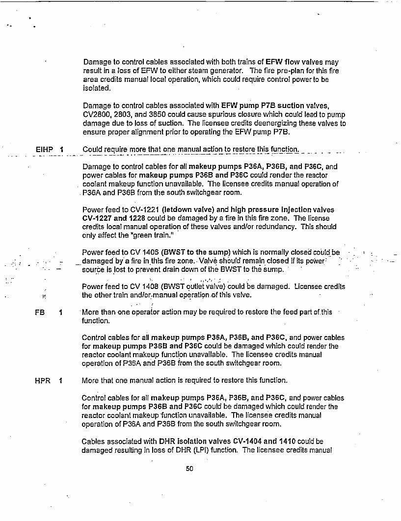
Damage to control cables associated with both trains of EFW flow valves mayresult in a loss of EFW to either steam generator. The fire pre-plan for this firearea credits manual local operation, which could require control power to beisolated.
Damage to control cables associated with EFW pump P7B suction valves,CV2800, 2803, and 3850 could cause spurious closure which could lead to pumpdamage due to loss of suction. The licensee credits deenergizing these valves toensure proper alignment prior to operating the EFW pump P7B.
EIHP I Could require more that one manual action to restore this function.
Damage to control cables for all makeup pumps P36A, P36B, and P36C, andpower cables for makeup pumps P36B and P36C could render the reactorcoolant makeup function unavailable. The licensee credits manual operation ofP36A and P36B from the south switchgear room.
Power feed to CV-1221 (letdown valve) and high pressure Injection valvesCV-1227 and 1228 could be damaged by a fire in this fire zone. The licensecredits local manual operation of these valves and/or redundancy. This shouldonly affect the "green train."
Power feed to CV 1406 (BWST to the sump) which is normally closed could bedamaged by'a fire in this fire zone.- Valve should remain closed if its power:source is lost to prevent drain down of the BWST to the sump.
Power feed to CV 1408 (BWST outlet valve) could be damaged. Licensee creditsthe other train and/or-manual operation of this valve.
FB 1 More than one operator action may be required to restore the feed part of thisfunction.
Control cables for all makeup pumps P36A, P36B, and P36C, and power cablesfor makeup pumps P36B and P36C could be damaged which could render thereactor coolant makeup function unavailable. The licensee credits manualoperation of P36A and P36B from the south switchgear room.
HPR I More that one manual action is required to restore this function.
Control cables for all makeup pumps P36A, P36B, and P36C, and power cablesfor makeup pumps P36B and P36C could be damaged which could render thereactor coolant makeup function unavailable. The licensee credits manualoperation of P36A and P36B from the south switchgear room.
Cables associated with DHR isolation valves CV-1404 and 1410 could bedamaged resulting in loss of DHR (LPI) function. The licensee credits manual
50

I-.
operation of these valves.
Seq I TRANS - PCS - EFW - FB = 0 + 1
2 TRANS - PCS - EFW-EIHP = 0+ 0 + 1
3 TRANS -PCS -EFW-HPR = 0 O + 1
Tb! 3.2 - Transients w/loss of PCS (TPCS)
_A fire-in Fire-Zone .98J,.could cause a-LOOP which results in losing the condensate pumpsresulting in loss of main feedwater, and a reactor trip on low SG level.
Secondary Heat Removal (EFW) 1/1 MDEFW trains (1 train) or I TDEFW train (1 ASD train)
High Pressure Injection (EIHP) Yz HPI trains from BWST or operator manually starts andaligns the swing pump (1 multi-train)
Primary Heat Removal, (FB) 111 ERVs or Y% SRVs open for Feed/Bleed and initiate HPIcooling (operator action = 2)
High Pressure Recirculation (HPR) /z HPI trains taking suction from 2 LPI trains through LPIHX (operator acti6n = 3)
EFW: 0- Too many manual actions are-required to ensure restoration of this function.
Damage to instrument cables for EFW pump P7A and control cables for EFWpump P7B could result in the loss of the operator's ability to control feedwater tothe steam generators. The licensee credits manual operation EFW pump P7B at -the breaker and local manual operation of EFW pump P7A.
Damage to control cables associated with both trains of EFW flow valves mayresult in a loss of EFW to either steam generator. The fire pre-plan for this firearea credits manual local operation, which could require control power to beisolated.
Damage to control cables associated with EFW pump P7B suction valves,CV2800, 2803, and 3850 could cause spurious closure which could lead to pumpdamage due to loss of suction. The licensee credits deenergizing these valves toensure proper alignment prior to operating the EFW pump P7B.
EIHP I Could require more that one manual action to restore this function.
Damage to control cables for all makeup pumps P36A, P3UB, and P36C, andpower cables for makeup pumps P36B and P36C could render the reactorcoolant makeup function unavailable. The licensee credits manual operation of
51

P36A and P36B from the south switchgear room.
Power feed to CV-1221 (letdown valve) and high pressure injection valvesCV-1227 and 1228 could be damaged by a fire in this fire zone. The licensecredits local manual operation of these valves and/or redundancy. This shouldonly affect the "green train."
Power feed to CV 1406 (BWST to the sump) which is normally closed could bedamaged by a fire in this fire zone. Valve should remain closed if its powersource is lost to prevent drain down of the BWST to the sump.
Power feed to.CVL1408-(BWST outlet-valve).could be damaged. -Licensee credits -
the other train and/or manual operation of this valve.
FB I More than one operator action may be required to restore the feed part of thisfunction.
Control cables for all makeup pumps P36A, P36B, and P36C, and power cablesfor makeup pumps P36B and P36C could be damaged which could render thereactor coolant makeup function unavailable. The licensee credits manualoperation of P36A and P36B from the south switchgear room.
HPR I More that one manual action is required to restore this function.
-Control cables for all makeup .pmps P36A, P36B, and P36C, and power cables- for makeup pumps P36B..and P36C could be damaged which could render the i
reactor coolant makeup function unavailable. The licensee credits manual-operation of P36A and P36B from the south switchgear room.
-wit *1404 and*14* Z... ... b
* , Cables associated wit..HiRisolation valves CV-1404 and 1410could bedamaged resulting in loss of DHR (LPI) function. The licensee credits manual..operation of these valves.
Seq. I TPCS - EFW- FB 0 + I
2 TPCS - EFW-EIHP 0 + 1
3 TPCS - EFW - HPR 0 1
Tbl 3.12 - Loss of Service Water (LSW)
A fire in this fire zone can result in spurious operation of numerous SW valves, loss of controlpower to numerous SW valves, and loss of SW pumps P4A, P4B, and P4C.
RCP Trip (RCPTRIP) Operator trips the RCPs to prevent a seal LOCA(operator action = 3)
52

W
Secondary Heat Removal (EFW) 1/1 MDEFW trains (1 train) or I TDEFWI train (1 ASD train)and secondary relief through 1/2 ADVs or 1/16 SRVs
RCPTRIP: 3 A fire in the switchgear room should not have an impact on the RCPs,therefore the operators will have to trip the RCPs to prevent a seal LOCA.
EFW: 0 Too many manual actions are required to ensure restoration of thisfunction.
Damage to instrument cables for EFW pump P7A and control cables forEFW pump P7B could result in the loss of the operator's ability to control
-- feedwater to the steam generators. .The licensee credits-manualoperation EFW pump P78 at the breaker, and local manual operation ofEFW pump P7A,* including manual operation of valves SV-2617,CV-2663, and/or CV-2667.
Damage to control cables associated with both trains of EFW flow valvesmay result in a loss of EFW to either steam generator. The fire pre-planfor this fire area credits manual local operation, which could requirecontrol power to be isolated.
Damage to control cables associated with EFW pump P7B suctionvalves, CV2800, 2803, and 3850 could cause spurious closure whichcould lead to pump damage due to loss of suction. The licensee credits
' .-deenbrgizing .these valves td ensure properialignmerit'pri6r to op&rating- . the EFVWpump P7B.- - -
* Seq I LSW EFW .*-.- 0 .,
- 2 LSW -RCPTRIP .. = -.: :Notapplicable .*; . . . . . . v b
Tbl 3.13 Loss of one Train of Support Systems (LITRAIN)
A fire in Fire Zone 99M can cause a loss of 4160V ac, 480V ac, 120V ac, and 125V dc power.The support systems listed in the notes to this table were SW, 4160V ac, 480V ac, and 125V dc.Since loss of SW is evaluated under Table 3.12, we solved the sequences associated with4160V ac, 480V ac, and 125V dc using this table.
Secondary Heat Removal (EFW) 1 TDEFW train (1 ASD train) with secondary relief through1/1 ADV or 1/8 SRVs
High Pressure Injection (EIHP) 1/1 HPI trains from BWST or operator manually starts andaligns the swing pump (1 multi-train system)
Primary Ht Removal, FdIBleed (FB) 111 ERVs or Y/2 SRVs open for Feed/Bleed and initiate HPIcooling (operator action = 2)
53

High Pressure Recirculation (HPR) 1/1 HPI trains ntaking suction from 1/1 LPI trains throughLPI HX (1 train)
EFW: 0 Too many manual actions are required to ensure restoration of this function.
Damage to instrument cables for EFW pump P7A and control cables for EFWpump P7B could result in the loss of the operator's ability to control feedwater tothe steam generators. The licensee credits manual operation EFW pump P7B atthe breaker and local manual operation of EFW pump P7A.
Damage to control cables associated with both trains of EFW flow valves mayresult in a loss of EFW to either steam generator. The fire pre-plan for-this firearea credits manual local operation, which could require control power to beisolated.
Damage to control cables associated with EFW pump P71B suction valves,CV2800, 2803, and 3850 could cause spurious closure which could lead to pumpdamage due to loss of suction. The licensee credits deenergizing these valves toensure proper alignment prior to operating the EFW pump P71.
EIHP I Could require more that one manual action to restore this function.
Damage to control cables for all makeup pumps P36A, P361, and P36C, andpower cables for makeup pumps P36B and P36C could-render the reactorcoolant makeup function unavailable. The licensee credits mnual operation of. - -
P36A and P36B from the south switchgear room. -
Power feed to CV-1221 (letdown valve) and high pressure Injection valvesItP. CV-1227 and 1228 could be damaged by a fire in this fire zone. The license . .*'- credits local manual operation of these valves and/or redundancy. This should -
only affect -the "greeriltrain."
Power feed to CV 1406 (BWST to the sump) which is normally closed could bedamaged by a fire in this fire zone. Valve should remain closed if its powersource is lost to prevent drain down of the BWST to the sump.
Power feed to CV 1408 (BWST outlet valve) could be damaged. Licensee creditsthe other train and/or manual operation of this valve.
FB 1 More than one operator action may be required to restore the feed part of thisfunction.
Control cables for all makeup pumps P36A, P36B, and P36C, and power cablesfor makeup pumps P36B and P36C could be damaged which could render thereactor coolant makeup function unavailable. The licensee credits manualoperation of P36A and P36B from the south switchgear room.
54

4F
J.
b
HPR I More that one manual action is required to restore this function.
Control cables for all makeup pumps P36A, P36B, and P36C, and power cablesfor makeup pumps P36B and P36C could be damaged which could render thereactor coolant makeup function unavailable. The licensee credits manualoperation of P36A and P36B from the south switchgear room.
Cables associated with DHR isolation valves CV-1404 and 1410 could bedamaged resulting in loss of DHR (LPI) function. The licensee credits manualoperation of these valves.
Loss of 4160V ac:
Seq. I LITRAIN - EFW - FB
2 LITRAIN - EFW -EIHP
3 LITRAIN - EFW - HPR
= 0 + I1 ,09
= 0 + I ~~
= 0 + I WWI
Loss of 480V ac:
Seq. I LITRAIN - EFW - FB (6)
-2 LITRAIN - EFW-EIHP (5)
3 LITRAIN - EFW - HPR (4)
= 0 + I 9M !W.- . I.oi "
= 0 * 1I i
t {D.* t/
Loss of 125V dc
Seq. I LITRAIN - EFW - FB (6)
2 LITRAIN - EFW -EIHP (5)
3 LITRAIN - EFW - HPR (4)
= 0 + 1
= -0+ 1
= 0 * I ahi"M_-
SUMMARY OF FINDINGS IN 99M: I150
55

ATTACHMENT 3
LIST OF COMPONEN4TS IN FIRE ZONES 98J AND 99M
Shortly after the inspection, Region IV requested a list and description of cables and components located inFire Zones 98J and 99M. On August 28, 2001, the licensee provided this list. Because of its late arrival,Region IV did not consider all the components shown on the list in the Phase 2 SDP. It is provided with thisTIA memo for use in performing the Phase 3 SDP. Please note that the list is not train specific and doesnot distiguish between power and control cables.
.
ICOMPONENENTS ASSUMED TO FAIL IN 98J
Equip COMPCODE ICOMP DESCRIPTIONA104 CKTBKR Al SWGR feeder breaker to 4160/480V transformer Xl4All1 CKTBKR SU Transformer #2 feeder breaker to Al (non-safety related) BusA111 RELAY SYNCH Check Relay for A 11 BreakerA202 CKTBKR A2 Bus feeder breaker to 4160/480V transformer X2A212 CKTBKR Unit Aux Transformer feeder breaker to A2 (non-safety related) BusA304 CKTBKR Reactor Building Spray Pump P-35A feeder breaker from A3 (red train) BusA307 CKTBKR Primary Makeup Pump P-36B feeder breaker from A3 BusA311 . CKTBKR Emergency Feedwater Pump P-7Bfeeder breaker from A3 Buls.A401 -- CKTBKR Vital A4 Bus feeder breaker to 4160/480V transformer X6A402 , CKTBKR Service Water Pump P-4C feeder breaker from A4 (green train) BusA403 CKTBKR Service Water Pump P-4B feeder breaker from A4 Bus - I IA601 Transfer Switch Breaker A403 to P-4B Motor Operator Disconnect (allows P-4B to be powered from
.__ _ _ _ _ _ _ _ _ _ _ _ A4 Bus)A404 CKTBKR Reactor Building Spray Pump P-35B feeder breaker from A4 BusA405 CKTBKR Decay Heat Pump P-34B feeder breaker from A4 BusA406 CKTBKR Primary Makeup Pump P-36C feeder breaker from A4 BusA407 CKTBKR Primary Makeup Pump P-36B feeder breaker from A4 BusA408 CKTBKR Emergency Diesel Generator #2 Output BreakerA409 CKTBKR Bus A4 feeder breaker from Bus A2B15 SWGEAR Non-Vital 480VAC Motor Control CenterB31 SWGEAR Non-Vital 480VAC Motor Control CenterB321 CKTBKR Non-Vital 480VAC Motor Control Center B31 feeder breaker from Non-Vital 480
VAC Bus B3B41 SWGEAR Non-Vital 480VAC Motor Control CenterB421 CKTBKR Non-Vital 480VAC Motor Control Center B41 feeder breaker from Non-Vital
480VAC Bus B4B4243 CKTBKR Feeder Breaker to Spare Instrument Air Compressor C2CB44 SWGEAR Non-Vital 480VAC Motor Control CenterB5123 CKTBKR Emergency Diesel Generator #1 (red train) Room Exhaust Fan VEF-24B supplyB5141A CKTBKR 120VAC Inverter YI I feeder breaker from Motor Control Center B51 (red train)
56

* b
B5145B CKTBKR 120VAC Inverter Y1 3 feeder breaker from Motor Control Center 853 (red train)B612 CKTBKR Vital 480VAC Bus B6 input supply breaker from Vital 4160VAC Bus A4B6123 CKTBKR Emergency Diesel Generator #2 (green train) Room Exhaust Fan VEF-24D supplyB614 CKTBKR Motor Control Center B62 feeder breaker from Vital 480VAC Bus B6 (green train)B623 CKTBKR Reactor Building Cooler VSF-1 C supply8633 CKTBKR Reactor Building Cooler VSF-1 D supplyB634 CKTBKR Motor Control Center B65 feeder breaker from Vital 480VAC Bus B6B64 SWGEAR Vital 480VAC Motor Control Center (green train)B65 SWGEAR Vital 480VAC Motor Control Center (green train)87 SWGEAR NonB71 SWGEAR NonB712- - CKTBKR- Motor Control Center1B71 feeder breaker from Bus B7B72 SWGEAR Non-Vital Motor Control Center 872C187 TRANSMITTE Steam Generator E24B Low Rangle Level Transmitter LT-2617 Transmitter
R BistableC2B COMPRESSO Spare Instrument Air Compressor C2B
RC3B COMPRESSO Sprare Instrument Air Compressor C3B
. R
CV1 000 VALVE Pressurizer ERV (Electromatic Relief Valve) IsolationCV1 009 VALVE Pressurizer Spray Block ValveCV1 206 /ALVE Reactor Coolant Pumps Seal Injection Block Valve from Makeup & Purification
SystemCV1221 VALVE Reactor Coolant System Letdown IsolationCV1227'v VALVE. : High Pressure Injection to Reactot-Coolant LoQp "B".lsblation-:CYV1228 VALVE High Pressure Injection to Reactor Coolant Loop."B"J JsolationCV1234 VALVE Reactor Coolant System MakeupCVU1274 .?' VALVE Reactor Coolant Pumps Seal Return Isolation back to Makeup Tank T4CV1400 IVALVE "B" Low Pressure Injection Isolation to RCS .CV1404 VALVE Decay Heat Pumps P-34A/B combined suction frorn'Reactor.Coblant SystemCVI406 VALVE Outboard Reactor Building Surnp Isolation to "B" Train HPI, LPI,;RB SprayCV1408 VALVE Borated Water Storage Tank (BWST) Outlet ValveCV1415 VALVE P34B/P35B (LPI & RB Spray Pump) Suction From RB SumpCV1416 VALVE Pressurizer Auxiliary Spray Containment Isolation From Decay Heat Sys.CV2235 VALVE Control Rod Drives (CRD) Cooling Water Supply RB Isolation From ICW SysCV2400 VALVE "B" Train RB Spray Header IsolationCV2613 VALVE P7A (Turbine Driven EFW Pump) Steam Admission ValveCV2617 VALVE "B" Steam Generator Supply Valve to P7ACV2618 VALVE "B" Steam Generator Atmospheric Dump Valve (ADV)CV2619 VALVE "B" Steam Generator ADV Block ValveCV2620 VALVE P7A to Steam Generator "B" IsolationCV2624 VALVE Main Feedwater Lo Load Block Valve (normally open) to "A" Steam GeneratorCV2625 VALVE Main Feedwater Block Valve to "A" Steam GeneratorCV2626 VALVE P-7B (Motor Driven) to "B" Steam Generator IsolationCV2627 VALVE P7A to "A" Steam Generator IsolationCV2630 VALVE Main Feedwater Reactor Building Isolation to "B" Steam Generator
57

I a I
CV2645 VALVE P7A to "A" Steam Generator solenoid operated control valveCV2646 VALVE P78 to "A" Steam Generator solenoid operated control valveCV2647 VALVE P7A solenoid operated control isolation valveCV2648 VALVE P78 to "B" Steam Generator solenoid operated controlCV2663 VALVE P7A steam admission valveCV2667 .VALVE P7A steam bypass valve from "A" Steam GeneratorCV2668 VALVE "A" Steam Generator Atmospheric Dump Valve (ADV)CV2670 VALVE P71 to "A" Steam Generator isolation (AC operated)CV2674 VALVE Main Feedwater Lo Load Block Valve (norrrally open) to "B" Steam GeneratorCV2675 VALVE Main Feedwater Block Valve to "B" Steam GeneratorCV2680 VALVE Main Feedwater Reactor Building Isolation to "A" Steam GeneratorCV2802-- VALVE - -- P7A-suction from Condensate Storage Tank -CV2827 VALVE Main Feedwater Cross Connect ValveCV2870 VALVE P7A Test & Recirc IsolationCV3640 VALVE P-4B ("B" Service Water Pump) to Service Water Loop II crossover valveCV3642 VALVE P4B to Service Water Loop II crossoverCV3806 VALVE #1 EDG Jacket Cooler (E-20A) service water supply isolation (loop 1)CV3807 VALVE #2 EDG Jacket Cooler (E-20B) service water supply isolation (loop 11)CV3811 VALVE Service Water Loop il supply to Intermediate Cooling Water (ICW) coolersCV3813 VALVE Service Water Loop II supply isolation to RB Cooling Coils (VCC-2C/2D)CV3821 VALVE Service Water Loop II supply isolation to "B" Decay Heat Cooler (E35B)CV3824 VALVE Combined Service Water return to Discharge Flume (lake)CV3841 - VALVE - Service water air operated isolation to "B" Decay Heat Pump Seal/Bearing CoolerCV561.1' VALVE . . Fire Waterfto Reactor Building Isolation - ..
C,7.472';. DAMPER Backdraft damper for.RB Ventillation Supply Fan VSF-1CCV7473;: DAMPER Backdraft damper for.RB Ventillation Supply Fan VSF-I DD0122A. CKTBKR DC Breaker to 120VAC Inverter.Y-11 (alternate source) -D02 i SWGEAR Green Train.125 VDC. Distribution BusD0222A.it CKTBKR DC Suppply Breaker to 120VAC. Inverter Y-24 (alterrate source)D03APB CHARGE 125 VDC'Battery Charger For D07(Red Train).D04AIB CHARGE 125 VDC Battery Charger For D06 (Green Train)D06 BATTERY 125 VDC Green Station Battery to 125 VDC Bus D02D1109 CKTBKR DC Control Power to Vital (Red) 480 VAC Load Center B5D1114 CKTBKR DC Control Power to #1 EDG Control Cabinet C-107 (Controls engine protective
trips)D1116 CKTBKR DC Control Power to #1 EDG Field Flashing & voltage regulator remote control
I (control room)D15 SWGEAR Non Vital 125 VDC BusD21 PANEL 125 VDC Motor Control Center (normal supply D02)D2104 CKTBKR DC Control Power to 4160 VAC Feeder Breaker A-409 (Bus A2 to A4 breaker)D2109 CKTBKR DC Control Power to Vital (Green) 480 VAC Load Center B6D2114 CKTBKR DC Control Power to #2EDG Control Cabinet C-108 (Controls engine protective
trips)D2116 CKTBKR DC Control Power to #2 EDG Field Flashing & Voltage regulator remote control
_(control room) . .D25 SWGEAR 125 VDC Motor Control Center
58
d
I
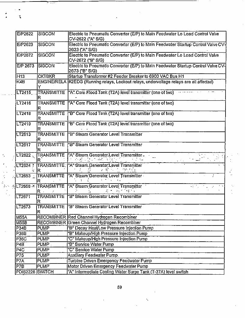
E/P2622 SIGCON Electric to Pneumatic Converter (E/P) to Main Feedwater Lo Load Control ValveCV-2622 ("A" S/G)
E/P2623 SIGCON Electric to Pneumatic Converter (E/P) to Main Feedwater Startup Control Valve CV2623 ("A" SIG)
E/P2672 SIGCON Electric to Pneumatic Converter (E/P) to Main Feedwater Lo Load Control ValveCV-2672 ("B" S/G)
EIP 2673 SIGCON Electric to Pneumatic Converter (E/P) to Main Feedwater Startup Control Valve CV2673 ("B" S/G)
H13 CKTBKR Startup Transformer #2 Feeder Breaker to 6900 VAC Bus HIK4B ENGINE/RELA #2EDG (Running relays, Lockout relays, undervoltage relays are all affected)
_Y
LT2415. TRANSMITTE -'A" Core Flood.Tank (T2A) level-transmitter (one of two)--R
LT2416 TRANSMITTE "A" Core Flood Tank (T2A) level transmitter (one of two)R
LT2418 TRANSMITTE "B" Core Flood Tank (T2A) level transmitter (one of two)
LT2419 TRANSMITTE "B" Core Flood Tank (T2A) level transmitter (one of two)R
LT2613 TRANSMITTE "B" Steam Generator Level Transmitter_R
LT2617 TRANSMITTE "B" Steam Generator Level TransmitterR
LT2622 TRANSMITTE "A" Steam. Generatqr:Level Transmitter-
LT2624 TRANSMITTE: "A" Stearn Generator.Level Transmitter
LT2653 TRANSMIT TE "A" Staeam.Generator Level TransmitterR . . ,
LT2668 . TRANSMITTE "A" Steam:Generator Levi.l-TransmitterR :_.:_-_,_ _ _
LT2671 TRANSMITTE "B" Steam Generator Level TransmitterR
LT2673 TRANSMITTE "B" Steam Generator Level TransmitterR
M55A RECOMBINER Red Channel Hydrogen RecombinerM55B RECOMBINER Green Channel Hydrogen RecombinerP34B PUMP "B" Decay Heat/Low Pressure Injection PumpP36B PUMP . "B" Makeup/High Pressure Injection PumpP36C PUMP "C" Makeup/High Pressure Injection PumpP4B PUMP "B" Service Water PumpP4C PUMP "C" Service Water PumpP75 PUMP Auxiliary Feedwater Pump.P7A PUMP Turbine Driven Emergency Feedwater PumpP7B PUMP Motor Driven Emergency Feedwater PumpPDIS2228 SWITCH "A" Intermediate Cooling Water Surge Tank (T-37A) level switch
:.I
59

- Z;
I I
PDT2700 TRANSMITTE Delta Pressure Valve Controller for CV-2625 ("A" S/G Main Feedwater Block ValveR
PDT2701 TRANSMITTE Delta Pressure Valve Controller for CV-2675 ("B" S/G Main Feedwater Block Valve)R
PS5432 SWITCH Autostart/Stop Pressure Switch for Backup Instrument Air Compressor C2BPS5436 SWITCH Autostart/Stop Pressure Switch for Service Air Compressor C3BPTI 020 TRANSMITTE "A" Reactor Coolant System Loop Pressure Transmitter (inputs to Engineered
_R Safeguards Actuation System Channnel 1)PTI 021 TRANSMITTE "A" Reactor Coolant System Loop Pressure Transmitter (inputs to Reactor
R Protection System)
PT1 022 TRANSMITTE "A" Reactor Coolant System Loop Pressure Transmitter (inputs to EngineeredR .. . Safeguards Actuation-System Channnel 2) .
PTI 040 TRANSMITTE "B" Reactor Coolant System Loop Pressure Transmitter (inputs to EngineeredR Safeguards Actuation System Channel 3)
PT2415 TRANSMITTE "A" Core Flood Tank (T2A) pressure transmitterR
PT2416 TRANSMITTE "A" Core Flood Tank (T2A) pressure transmitterR
PT2418 TRANSMITTE "B" Core Flood Tank (T2B) pressure transmitterR
PT2419 TRANSMITTE "B" Core Flood Tank (T2B) pressure transmitterR
PT2617A TRANSMITTE "B" Steam Generator pressure transmitter for Main Steam Line Isolation ;(MSLI). _ _ .. - _
PT2618B, TRANSMITTE "A" Steam Generator pressure transmitter-for Main Steam Line.Isolation (MSLI)-
PT2667B. TRANSMITTE. "B" Steam Generator pressure transmitter for Main Steam Line Isolation (MSLI)
PT2668A TRANSMITTE "A" Steam Generator pressuie transmitter for Main Steam Line isolation (MSLI)R ..
RA1 PANEL 125 VDC Distribution Panel (fed from D01)
RA2 PANEL 125 VDC Distribution Panel (fed from D02)
RS2 PANEL Vital 120 VAC Distribution Panel (fed from inverters Y22 orY25)RS4 PANEL Vital 120 VAC Distribution Panel (fed from inverters Y24 or Y25)
SV2229 VALVE "B" Intermediate Cooling Water Surge Tank (T37B) fill makeup solenoid valve (fromcondensate makeup)
SV2250 VALVE "B" Service Air Compressor After Air Cooler solenoid valve (supplies ICW thrucooler on compressor start)
SV2252 VALVE "B" Backup Instrument Air Compressor cooling water inlet ( for cylinder jacket._ cooling)
SV2254 VALVE "B" Backup Instrument Air Compressor After Air Cooler solenoid valve (suppliesICW thru cooler on compressor start)
SV3841 VALVE Service Water to "B" Decay Heat Pump (P-34B) Seal/Bearing Cooler
60
i..
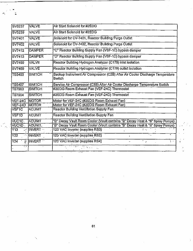
SV5237 VALVE Air Start Solenoid for #2EDG
SV5239 VALVE Air Start Solenoid for #2EDG
SV7401 VALVE Solenoid for CV-7401, Reactor Building Purge Outlet
SV7402 VALVE Solenoid for CV-7402, Reactor Building Purge Outlet
SV7412 DAMPER "C" Reactor Building Supply Fan (VSF-1C) bypass damper
SV7413 DAMPER "D" Reactor Building Supply Fan (VSF-1D) bypass damper
SV7459 VALVE Reactor Building Hydrogen Analyzer (C179) inlet isolation
SV7469 VALVE Reactor Building Hydrogen Analyzer (C179) outlet isolation
TS5403 -SWITCH - Backup Instrument AirWCo-rmpressor (C2B) After Air Cooler Discharge TemperatureSwitch
TS5407 SWITCH Service Air Compressor (C3B) After Air Cooler Discharge Temperature SwitchTS7903 SWITCH #2EDG Room Exhaust Fan (VEF-24C) Thermostat
TS7904 SWITCH #2EDG Room Exhaust Fan (VEF-24D) Thermostat
VEF-24C MOTOR Motor for VEF-24C (#2EDG Room Exhaust Fan)VEF-24D MOTOR Motor for VEF-24C (#2EDG Room Exhaust Fan)VSF1C ACUNIT Reactor Building Ventillation Supply Fan
VSF1 D ACUNIT Reactor Building Ventillation Supply Fan
VUC1 C. ACUNIT "B" Decay Vault Room Cooler (Vault contains "B" Decay Heat & "B" Spray Pumps)VUCI D. AOUNITL . "B" Decay Vault Room Cooler (Vault contains "B" Decay Heat & "B" Spray Pumps)Y13 ' INVERT 120 VAC Inverter (supplies RS3) .
Y22 INVERT 120 VAC-lnverter (supplies RS2) -
Y24 ir INVERT 120 VAC Inverter (supplies RS4) -
, ,. ... ,...
61

I JCOMPONENTS ASSUMED TO FAIL IN 99M
TAG JCOMPCODE ICOMP DESCRIPTION
A104 CKTBKR 4160 VAC Bus Al Feed to 4160-480 VAC Transformer (Feeds 480 VACBus B14)
A304 CKTBKR Reactor Building Spray Pump (P-35A) Supply Breaker
A307 CKTBKR Primary Makeup / High Pressure Injection Pump P-36B Supply Breaker
A308 CKTBKR Emergency Diesel Generator #1 Output Breaker
A311 CKTBKR Emergency Feedwater Pump P-7B (Motor Driven) Supply Breaker
A4 SWGEAR Vital 4160 VAC Bus A4
A401 CKTBKR 4160 VAC Bus A4 Feed to 416-480 VAC Transformer X6 (Feeds 480VAC Bus B6)
A402 CKTBKR Service Water Pump P-4C Supply Breaker
A403 CKTBKR Service Water Pump P-4B Supply Breaker from Bus A4
A404 CKTBKR Reactor Building Spray Pump P-35B Supply Breaker
A405 CKTBKR Decay Heat Pump P-348 Supply Breaker
A406 CKTBKR Primary Makeup IHigh Pressure Injection Pump P-36C Supply Breaker
A407 CKTBKR Primary Makeup /High Pressure Injection Pump P-36B Supply Breaker____._-_._. from BLs-A4
A408 CKTBKR Emergency:Diesel.Generator#2 Output Breaker ,;. .
A409°. CBKR 4160 VAC Supply Breaker from Bus A2 to A4
A601 CKTBKR Motor pperated Disconnect for Breaker A403 (Supply'to Service Water-. ___ ___ _ Pump P-4.B).
B15 SWGEAR Non Vital 480 VAC Motor Control Center
831 SWGEAR Non Vital 480 VAC Motor Control Center
B41 SWGEAR Non Vital 480 VAC Motor Control Center
B43 SWGEAR Non Vital 480 VAC Motor Control Center
844 SWGEAR Non Vital 480 VAC Motor Control Center
B55 SWGEAR Vital 480 VAC Motor Control Center from Load Center B5
856 SWGEAR Vital 480 VAC Motor Control Center from Load Center B5
85622B CKTBKR Temporary Power for Battery Charger D03B or D04B (outage relatedactivity)
B5553 CKTBKR Feeder Breaker to CV-3643 (Service Water to Aux Cooling Water ISOVlv
B57 SWGEAR Vital 480 VAC Motor Control Center from Load Center B5
B6 SWGEAR Vital 480 VAC Load Center
62

B61 SWGEAR Vital 480 VAC Motor Control Center from Load Center B6
B612 CKTBKR Input Supply Breaker to 480 VAC Bus B6 From 4160 VAC Bus A4
B6123 CKTBKR Supply Breaker to #2EDG Room Exhaust Fan VEF-24D
B614 CKTBKR Supply Breaker to 480 VAC Motor Control Center B62 from 480 VACLoad Center B6
B6145A CKTBKR Normal AC input Supply Breaker to 120 VAC inverter Y-24 from 480VAC Motor Control Center B61
B62 SWGEAR Vital 480 VAC Motor Control Center
8621 CKTBKR Supply breaker to 480 VAC Motor Control Center 861 from 480 VAC. ..... Load Center B6- - -
B622 CKTBKR 480 VAC Supply to Motor Control Center B56 from Load Center B6
8623 CKTBKR Supply Breaker to Reactor Building Ventillation Supply Fan VSF-1C
B633 CKTBKR Supply Breaker to Reactor Building Ventillation Supply Fan VSF-1 D
B634 CKTBKR Supply Breaker to Motor Control Center B-65 From 480 VAC LoadCenter B6
B64 SWGEAR Vital 480 VAC Motor Control Center
B65 SWGEAR Vital 480 VAC Motor Control Center
87 SWGEAR Non Vital 480 VAC Motor Control Center
B712. CKTBKR Input Supply Breaker to 480 VAC Eus B7 from 4160 VAC Bus A1
B72:. - SWGEAR - Nonl Vital 480-VAC Motor Control Center from Load Center B7
C18U.- BISTBL Senses LT-2617 ("B" Steam.,Generator Level) & and feeds that Input toC187 (Emergency Feedwater Initiation Control Cabinet)
CV1009 VALVE Pressurizer Spray Block ValveCV1206 VALVE Reictor Coolant Pump Seal.!piection Block Valve.(from Makeup &.___.._ Purification System)CV1404 VALVE Decay Heat Pumps P-34A/B Suction From RCSCV1416 VALVE Pressurizer Auxiliary Spray Containment Isolation ValveCV2235 VALVE Control Rod Drive Mechanisms (CRDM) Cooling Supply Reactor
._ _ Building Isolation (from Intermediate Cooling Water)CV2617 VALVE "B" Steam Generator Steam Supply to Emergency Feedwater Pump P-
7ACV2618 VALVE "B" Steam Generator Atmospheric Dump Valve (ADV)CV2625 VALVE Main Feedwater Block Valve to "A" Steam GeneratorCV2627 VALVE Turbine Driven Emergency Feedwater Pump P-7A to "A" Steam
Generator Isolation (AC powered)
CV2630 VALVE Main Feedwater Isolation to "B" Steam GeneratorCV2646 VALVE Motor Driven Emergency Feedwater Pump P-7B to "A" Steam Generator
Isolation (DC powered)
CV2663 VALVE Turbine Driven Emergency Feedwater Pump P-7A Steam Admission vIvIValve
63

-
CV2667 VALVE "A" Steam Generator Steam Supply Bypass to Turbine DrivenEmergency Feedwater Pump P-7A
CV2668 VALVE "A" Steam Generator Atmospheric Dump ValveCV2674 VALVE Main Feedwater Lo Load Block Valve to "B" Steam Generator (normally
open)CV2680 VALVE Main Feedwater Isolation to "A" Steam GeneratorCV2802 VALVE Turbine Driven Emergency Feedwater Pump P-7A suction from
Condensate Storage Tank (CST)
CV3640 VALVE "B" Service Water Pump P-4B Discharge Cross Over Valve to Loop IIService Water
CV3642 VALVE "B" Service Water Pump P-4B Discharge Cross Over Valve to Loop II. . . Service Water
CV3643 VALVE Service Water to Auxiliary Cooling Water IsolationCV3821 VALVE Loop II Service Water Supply Isolation to "B" Decay Heat Cooler E-35BCV3841 VALVE Loop II Service Water Supply Isolation to E-50B ("B" Decay Heat Pump
Bearing/Seal Cooler)
CV5611 VALVE Fire Water to Reactor Building IsolationCV7472 DAMPER Backdraft damper for RB Ventillation Supply Fan VSF-1 CCV7473 DAMPER Backdraft damper for RB Ventillation Supply Fan VSF-1 DD1109 CKTBKR DC Control Power to Vital (Red) 480 VAC Load Center B5
D15 SWGEAR Non Vital 125 VDC Bus
D9104 C.KTBKR DC Control Power-to 4160VACFeederE;reakerA:409(Bus A2 to A4. ._ breaker) - -
D2109 ;; CKTBKR DC Control Power to Vital .(Green) 480 VAC Load Center.B6 !
K4B; ENGINE/RELAY 2EDG (Running relays, Lockout relays, undervoltage relays are all. .affected)
LT2617. TRANSMITTER "B" Steam Generator. Level Transmitter ' : -';.
LT2668 TRA14SMITTER "A" Steam Generator Level TransmitterM55A RECOMB Red Channel Hydrogen Recombiner
P34B PUMP "B" Decay Heat Pump
P36B PUMP "B" Makeup/High Pressure Injection Pump
P36C PUMP "C" Makeup/High Pressure Injection Pump
P4B PUMP "B" Service Water Pump
P4C PUMP "C" Service Water Pump
P7A PUMP Turbine Driven Emergency Feedwater Pump
PT2617 TRANSMITTER "B" Steam Generator pressure transmitter for Main Steam Line IsolationA (MSLI)
PT2668 TRANSMITTER "A" Steam Generator pressure transmitter for Main Steam Line IsolationA (MSLI)
RS2 PANEL Vital 120 VAC Distribution Panel (fed from inverters Y22 or Y25)
64

: %
. , - 7-
RS4 PANEL Vital 120 VAC Distribution Panel (fed from Inverters Y24 or Y25)
SG2 VALVE Lake Supply Isolation to "A" Service Water Bay ("A" Service WaterPump P4A is located in this bay)
SG4 VALVE "C" Service Water Bay to "B" Service Water Bay Isolation (may beclosed depending on service water pump configuration)
SV3805 VALVE Solenoid Valve to supply air to CV-3805 ("B" Reactor Building Spray. Pump Bearing/Seal Cooler E-47B)
SV3841 VALVE Solenoid Valve to supply air to CV-3805 ("B" Decay Heat Bearing/SealCooler E-50B)
SV5237 VALVE Air Start Solenoid for #2EDGSV5239 VALVE Air Start Solenoid for #2EDGVSF1 C ACUNIT Reactor Building Ventillation Supply Fan
VSF1 D ACUNIT Reactor Building Ventillation Supply FanVUC1 D ACUNIT "B" Decay Vault Room Cooler (Vault contains "B" Decay Heat & "B"
Spray Pumps)VUC7B ACUNIT "B" Makekup/HPI Room Cooler
X6 TRANSFORME 4160/480 VAC Transformer from Bus A4 to B6R
Y22 INVERT 120 VAC Inverter (supplies RS2)
Y24 INVERT 120 VAC Inverter (supplies RS4)
*. . ... . , , _
65


![Visual Weld Inspection Guidelines Attachment A - Raytheon ...2].pdf · Visual Weld Inspection Guidelines Attachment A ... the controlling specifications AWS D17.1 and the ... such](https://img.dokumen.tips/doc/110x75/5a79e0487f8b9a3d058b4c25/visual-weld-inspection-guidelines-attachment-a-raytheon-2pdfvisual-weld.jpg)


![Visual Weld Inspection Guidelines Attachment A - …2].pdf · Visual Weld Inspection Guidelines Attachment A ... approved weld inspector shall document weld inspection results using](https://img.dokumen.tips/doc/110x75/5a78aa797f8b9a21538b97b6/visual-weld-inspection-guidelines-attachment-a-2pdfvisual-weld-inspection.jpg)