Embed Size (px)
Citation preview

ATSC S32-266r16 Scheduler / Studio to Transmitter Link 30 September 2016
i
ATSC Candidate Standard: Scheduler / Studio to Transmitter Link
Doc. S32-266r16 30 September 2016
Advanced Television Systems Committee 1776 K Street, N.W. Washington, D.C. 20006 202-872-9160

ATSC S32-266r16 Scheduler / Studio to Transmitter Link 30 September 2016
ii
The Advanced Television Systems Committee, Inc., is an international, non-profit organization developing voluntary standards for digital television. The ATSC member organizations represent the broadcast, broadcast equipment, motion picture, consumer electronics, computer, cable, satellite, and semiconductor industries.
Specifically, ATSC is working to coordinate television standards among different communications media focusing on digital television, interactive systems, and broadband multimedia communications. ATSC is also developing digital television implementation strategies and presenting educational seminars on the ATSC standards.
ATSC was formed in 1982 by the member organizations of the Joint Committee on InterSociety Coordination (JCIC): the Electronic Industries Association (EIA), the Institute of Electrical and Electronic Engineers (IEEE), the National Association of Broadcasters (NAB), the National Cable Telecommunications Association (NCTA), and the Society of Motion Picture and Television Engineers (SMPTE). Currently, there are approximately 150 members representing the broadcast, broadcast equipment, motion picture, consumer electronics, computer, cable, satellite, and semiconductor industries.
ATSC Digital TV Standards include digital high definition television (HDTV), standard definition television (SDTV), data broadcasting, multichannel surround-sound audio, and satellite direct-to-home broadcasting.
Note: The user's attention is called to the possibility that compliance with this standard may require use of an invention covered by patent rights. By publication of this standard, no position is taken with respect to the validity of this claim or of any patent rights in connection therewith. One or more patent holders have, however, filed a statement regarding the terms on which such patent holder(s) may be willing to grant a license under these rights to individuals or entities desiring to obtain such a license. Details may be obtained from the ATSC Secretary and the patent holder.
This specification is being put forth as a Candidate Standard by the TG3/S32 Specialist Group. This document is a revision of the Working Draft (S32-266r15) dated 9 September 2016. All ATSC members and non-members are encouraged to review and implement this specification and return comments to [email protected]. ATSC Members can also send comments directly to the TG3/S32 Specialist Group. This specification is expected to progress to Proposed Standard after its Candidate Standard period.
Revision History Version Date Candidate Standard approved 30 September 2016 Standard approved Date

ATSC S32-266r16 Scheduler / Studio to Transmitter Link 30 September 2016
iii
Table of Contents 1. SCOPE ..................................................................................................................................................... 1
1.1 Introduction and Background 2 1.2 Organization 2
2. REFERENCES ......................................................................................................................................... 2 2.1 Normative References 2
3. DEFINITION OF TERMS .......................................................................................................................... 3 3.1 Compliance Notation 3 3.2 Treatment of Syntactic Elements 4
3.2.1 Reserved Elements 4 3.3 Acronyms and Abbreviation 4 3.4 Terms 5
4. SYSTEM OVERVIEW ............................................................................................................................... 5 4.1 Features 5 4.2 Detailed System Architecture 8
4.2.1 System Manager 9 4.2.2 Scheduler 9 4.2.3 Studio to Transmitter(s) Dataflow 10 4.2.4 Transmitter operation 10 4.2.5 STL / SFN operation 10
4.3 Central Concepts ALPTP 10 4.3.1 IP Multicast 10 4.3.2 Address Assignments 10 4.3.3 Port Assignments 11
4.4 Central Concepts of STLTP 11 4.4.1 IP protocol stack 11 4.4.2 IP multicast 11 4.4.3 Address assignments 11 4.4.4 Port Assignments 11 4.4.5 Error Control Coding Scheme 11
4.5 System Time Domains 11 4.6 System Manager Configuration Interface 12 4.7 Real Time Control Interface 12 4.8 SFN Operation 12 4.9 Bonded-Channel Operation 12 4.10 Receiver Assumptions? 12
5. SCHEDULER DESCRIPTION AND NORMATIVE REQUIREMENTS ................................................... 12 5.1 Relationship of Broadcast Gateway and Scheduler to the System 12 5.2 Scheduler Function 14 5.3 Scheduler Input Ports 15
5.3.1 Scheduler Management Port 17 5.3.2 Scheduler Control Port 17
5.4 Scheduler Operation 18 5.4.1 Key Concepts Scheduler Delivery Metadata 19

ATSC S32-266r16 Scheduler / Studio to Transmitter Link 30 September 2016
iv
5.4.2 Handling Boundary Conditions 22 5.4.3 Delivery Order Within and Across Multiple ROUTE Sessions 23 5.4.4 Timelines and Deadlines 25 5.4.5 Concept and Practice of Analyzed Media Duration 25 5.4.6 Sequence of Required Data and Media Events for Acquisition 27
5.5 Summary of Requirements 28 6. ALP TRANSPORT PROTOCOL ............................................................................................................ 29
6.1 Overview 29 6.2 RTP/UDP/IP Multicast Considerations 30 6.3 ALPTP Design 30 6.4 Multicast Addressing 33
7. STL TRANSPORT PROTOCOL ............................................................................................................. 33 7.1 Preamble Data Generator 33
7.1.1 Preamble Data Stream Protocol 34 7.2 Timing Data Generator 35
7.2.1 Timing and Management Data Stream Protocol 36 7.2.2 Bootstrap Emission Timing and Frame Identification 40 7.2.3 PLP Data Stream 40 7.2.4 Baseband Frame Data Stream Protocol 40
7.3 Studio to Transmitter Link (STL) Protocol Overview 41 7.4 STL Transmission Protocol Design 42
7.4.1 Example SMPTE 2022-1 FEC Encoding Process 43 7.5 RTP Header Field Definitions 45
7.5.1 RTP Encapsulation Example 47 7.6 SMPTE ST 2022-1 Features / Resources 48
8. TRANSMITTER OPERATION NORMATIVE REQUIREMENTS ............................................................ 48 8.1 Timing Manager 48 8.2 Preamble Parser 49 8.3 Buffer models 50 8.4 Buffer requirements 50 8.5 Other Requirements 51
8.5.1 Frequency Accuracy 51 8.5.2 Timing Offsets 52
ANNEX A : PHYSICAL LAYER CONTROL .................................................................................................. 53 A.1 PHysical layer resources 53
A.1.1 Bootstrap Signaling 53 A.1.2 L1-Basic Signaling 53 A.1.3 L1-Detail signaling 55
ANNEX B NETWORK CONFIGURATION EXAMPLES ................................................................................ 58 B.1 Example studio network topologies 58

ATSC S32-266r16 Scheduler / Studio to Transmitter Link 30 September 2016
v
Index of Figures and Tables Figure 1.1 In scope interfaces description. .................................................................................... 1 Figure 4.1 High level overview of system configuration. .............................................................. 6 Figure 4.2 System architecture. ...................................................................................................... 9 Figure 5.1 A Broadcast Gateway conceptual diagram. ................................................................ 13 Figure 5.2 Synchronization of multiple Broadcast Gateways. ..................................................... 14 Figure 5.3 Cascade of real time functions involved with Scheduler. .......................................... 18 Figure 5.4 Example depiction of a high level scheduler process flow. ....................................... 19 Figure 5.5 Illustration of earliest and latest time with a block interleaver. .................................. 20 Figure 5.6 Illustration of Earliest and Latest Time options relative to Media Segment play. ..... 20 Figure 5.7 Example of MDE and associated earliest and latest. .................................................. 21 Figure 5.8 Relationship of an MDE in LCT packets to IP encapsulation. ................................... 22 Figure 5.9 Media is sent at early boundary; e.g., Period start. ..................................................... 23 Figure 5.10 Example of ordered delivery across multiple sessions. ............................................ 24 Figure 5.11 Explicit delivery order on PLP with multiple sessions. ............................................ 24 Figure 5.12 Analyzed Media Duration. ....................................................................................... 26 Figure 5.13 Order of events to optimize linear service acquisition w/wo an app. ....................... 28 Figure 7.1 STL transmission diagram. ......................................................................................... 42 Figure 7.2 Example FEC encoding process diagram. .................................................................. 44 Figure 7.3 RTP Encapsulation example diagram. ........................................................................ 47 Figure 8.1 ALP buffer latency. .................................................................................................... 50 Figure B.1.1 Simple ALP encapsulation. ..................................................................................... 58 Figure B.1.2 Multiple PLP example. ........................................................................................... 59 Figure B.1.3 Fully redundant routing example. ........................................................................... 60 Table 5.1 Scheduler Ports ............................................................................................................. 16 Table 6.1 RTP Header Field Definitions for ALP Encapsulation ................................................ 31 Table 6.2: ALP RTP Packet payload_type Encoding ................................................................. 32 Table 6.3 Timestamp Field Definitions for ALP Encapsulation .................................................. 33 Table 7.1 Preamble Payload ......................................................................................................... 34 Table 7.2 RTP Header Timestamp Field Definitions ................................................................... 35 Table 7.3 Timing and Management Stream Packet Payload ....................................................... 37 Table 7.4: RTP Header Field Definitions for STLTP .................................................................. 45

ATSC S32-266r16 Scheduler / Studio to Transmitter Link 30 September 2016
1
ATSC Candidate Standard: Scheduler / Studio to Transmitter Link
1. SCOPE This standard specifies the protocol on the Single Frequency Network (SFN) interface from studio side infrastructure to SFN of transmitters. The document also defines possible interfaces among the studio infrastructure for example the interconnection of the ATSC Link Layer Protocol (ALP) and a Broadcast Gateway. This document specifies certain constraints on the scheduling of content and signaling on the physical layer. The described scheduling process enables preamble generation and emission time management. It specifies certain aspects of transmitter behavior and certain parameters of transmitter operation with protocols over a Studio-to-Transmitter (STL) link. Figure 1.1 depicts an example configuration and connection of these entities. This document provides no specification of broadband delivery.
Single Transmitteror
SFN of Transmitters
Studio Infrastructure
BroadcastGateway
System Manager
Studio Entities
Quasi-static Configuration
DeliveryMetadata
Content and Signaling
StudioInterface
STLInterface
ConfigurationInterface
Figure 1.1 In scope interfaces description.
This standard specifies the interconnection between the transport and physical layers as well as a number of technologies and protocols necessary for practical implementation of the physical layer. In particular, it specifies the interconnection of ATSC Link Layer Protocol (ALP) packets with transmitters. It defines delivery protocols for ALP Transport and for Studio-to-Transmitter Link (STL) transport. It provides for management of physical layer data structure construction through definition of a Scheduler function. It defines the processes of Preamble generation and emission timing management. It specifies certain aspects of transmitter behavior and certain parameters of transmitter operation. It makes no specification of the Internet side of hybrid delivery.

ATSC S32-266r16 Scheduler / Studio to Transmitter Link 30 September 2016
2
1.1 Introduction and Background The ATSC 3.0 system comprises a number of layers that must be connected to one another to construct a complete implementation. Two of the layers that must be interconnected are the transport layer and the physical layer. In addition, the physical layer is designed to be implemented partially at the studio or data source and partially at one or more transmitters. To enable the necessary interoperation of the layers and system segments, appropriate protocols are necessary so that equipment from multiple suppliers can be assembled into a working system. This document defines two protocols, the ATSC Link-Layer Protocol Transport Protocol (ALPTP) and the Studio-to-Transmitter Link Transport Protocol (STLTP), for carriage of data through specific portions of the system, as well as a number of operational characteristics of the STL and transmitter(s). Also defined are a Scheduler to manage operation of the physical layer subsystems and two protocols used by the Scheduler (1) to receive high-level configuration instructions from a System Manager and (2) to provide real-time bit-rate control information to data sources sending content through the transport layer for emission by the physical layer.
1.2 Organization This document is organized as follows:
• Section 1 – Outlines the scope of this document and provides a general introduction. • Section 2 – Lists references and applicable documents. • Section 3 – Provides a definition of terms, acronyms, and abbreviations for this
document. • Section 4 – System overview • Section 5 – Scheduler of physical layer resources • Section 6 – ALP transfer protocol • Section 7 – Studio to Transmitter Link protocol • Section 8 – Transmitter operation • Annex A – Physical layer control • Annex B – Network Configurations
2. REFERENCES All referenced documents are subject to revision. Users of this Standard are cautioned that newer editions might or might not be compatible.
2.1 Normative References The following documents, in whole or in part, as referenced in this document, contain specific provisions that are to be followed strictly in order to implement a provision of this Standard. [1] IEEE: “Use of the International Systems of Units (SI): The Modern Metric System,” Doc.
SI 10, Institute of Electrical and Electronics Engineers, New York, N.Y. [2] ATSC: “ATSC Standard: System Discovery and Signaling,” Doc. A/321:2016, Advanced
Television System Committee, Washington, D.C., 23 March 2016. [3] ATSC: “ATSC Standard: Physical Layer Protocol,” Doc. A/322:2016, Advanced
Television System Committee, Washington, D.C., 7 September 2016.

ATSC S32-266r16 Scheduler / Studio to Transmitter Link 30 September 2016
3
[4] ATSC: “ATSC Candidate Standard: Signaling, Delivery, Synchronization, and Error Protection,” Doc. A/331, Advanced Television System Committee, Washington, D.C., 21 June 2016.
[5] ATSC: “ATSC Standard: Link Layer Protocol,” Doc. A/330:2016, Advanced Television System Committee, Washington, D.C., 19 September 2016.
[6] IETF: “RTP protocol,” RFC 3550, Internet Engineering Task Force. [7] IETF: “RTP Profile for Audio and Video Conferences with Minimal Control,” RFC 3551,
Internet Engineering Task Force. [8] SMPTE: “Forward Error Correction for Real-Time Video/Audio Transport Over IP
Networks,” Doc. SMPTE 2022-1-2007, Society of Motion Picture and Television Engineers, White Plains, NY, 2007.
[9] IETF: “Generic FEC Payload Format,” RFC 5109 (which supersedes IETF RFC 2733), Internet Engineering Task Force.
[10] SMPTE: “Broadcast Exchange Format (BXF) – Protocol,” Doc. SMPTE 2021-2:2012, Society of Motion Picture and Television Engineers, White Plains, NY, 2012.
[11] SMPTE: “Media Device Control Protocol (MDCP),” Doc. SMPTE 2071-2:2014, Society of Motion Picture and Television Engineers, White Plains, NY, 2014.
[12] ITU-T, “V.41 Data Communication Over the Telephone Network, Code-Independent Error-Control System,” 1993 (or later, if available).
[13] IEEE: “IEEE Standard for a Precision Clock Synchronization Protocol for Networked Measurement and Control Systems,” Doc. 1588, Institute of Electrical and Electronics Engineers, New York, NY, approved 27 March 2008.
[14] SMPTE: “SMPTE Profile for Use of IEEE-1588 Precision Time Protocol in Professional Broadcast Applications,” Doc. SMPTE ST-2059-2, 2015, Society of Motion Picture and Television Engineers, White Plains, NY, 2015.
[15] IETF: “Network Time Protocol Version 4: Protocol and Algorithms Specification,” RFC 5905, D. Mills, J. Martin, J. Burbank, W. Kasch, Internet Engineering Task Force, June 2010.
[16] W3C Date and Time Formats, Misha Wolf, Charles Wicksteed, August 27, 1998. [17] “International Atomic Time,” International Bureau of Weights and Measures. Retrieved 22
February 2013.
3. DEFINITION OF TERMS With respect to definition of terms, abbreviations, and units, the practice of the Institute of Electrical and Electronics Engineers (IEEE) as outlined in the Institute’s published standards [1] shall be used. Where an abbreviation is not covered by IEEE practice or industry practice differs from IEEE practice, the abbreviation in question will be described in Section 3.3 of this document.
3.1 Compliance Notation This section defines compliance terms for use by this document: shall – This word indicates specific provisions that are to be followed strictly (no deviation is
permitted). shall not – This phrase indicates specific provisions that are absolutely prohibited.

ATSC S32-266r16 Scheduler / Studio to Transmitter Link 30 September 2016
4
should – This word indicates that a certain course of action is preferred but not necessarily required.
should not – This phrase means a certain possibility or course of action is undesirable but not prohibited.
3.2 Treatment of Syntactic Elements This document contains symbolic references to syntactic elements used in the audio, video, and transport coding subsystems. These references are typographically distinguished by the use of a different font (e.g., restricted), may contain the underscore character (e.g., sequence_end_code) and may consist of character strings that are not English words (e.g., dynrng). 3.2.1 Reserved Elements One or more reserved bits, symbols, fields, or ranges of values (i.e., elements) may be present in this document. These are used primarily to enable adding new values to a syntactical structure without altering its syntax or causing a problem with backwards compatibility, but they also can be used for other reasons.
The ATSC default value for reserved bits is ‘1.’ There are no default values for other types of reserved elements. Use of reserved elements except as defined in ATSC Standards or by an industry standards setting body is not permitted. See individual element semantics for mandatory settings and any additional use constraints. As currently-reserved elements may be assigned values and meanings in future versions of this Standard, receiving devices built to this version are expected to ignore all values appearing in currently-reserved elements to avoid possible future failure to function as intended.
3.3 Acronyms and Abbreviation The following acronyms and abbreviations are used within this document. ALP ATSC 3.0 Link-Layer Protocol ALPTP LP Transport Protocol ATSC Advanced Television Systems Committee bslbf bit stream, left-most bit first CRC cyclic redundancy check DASH Dynamic Adaptive Streaming over HTTP DDE Data Delivery Event ECC Error Correction Coding FEC Forward Error Correction IP Internet Protocol IS Initialization Segment LMT Layer Mapping Table MDE Media Delivery Event MPD Media Presentation Description MTU Maximum Transfer Unit NAL Network Adaption Layer PLP Physical Layer Pipe ROHC-U Robust Header Compression UDP ROUTE Real-time Object delivery over Unidirectional Transport

ATSC S32-266r16 Scheduler / Studio to Transmitter Link 30 September 2016
5
RTP Real-time Transport Protocol SFN Single Frequency Network SLS Service Layer Signaling SLT Service List Table STL Studio–to-Transmitter Link STLTP Studio–to-Transmitter Link Transport Protocol tcimsbf two’s complement integer, msb first UDP User Datagram Protocol uimsbf unsigned integer, most significant bit first
3.4 Terms The following terms are used within this document. Broadcast Gateway – A Broadcast Gateway converts source file objects for example media,
system information, and other opaque files into SFN baseband description for distribution to transmitters.
Cell – A single transmitter or an SFN Earliest Time – TBD Latest Time – TBD Multiplex – A group of services that are transmitted together over a network Network – A group of transmitters delivering the same multiplex Packet Set – A group of packets carrying segments of a large data structure that has been
segmented for the purpose of carriage across a transport connection that is not configured to carry the large data structure.
reserved – Set aside for future use by a Standard. SFN – Multiple transmitters in proximity to one another radiating the same waveform and
sharing a frequency Scheduler – Studio side function that allocates physical capacity to Services based on temporal
demand and or requests reductions in demand. SFN Interface – The SFN Interface is the origin point the Studio–to-Transmitter Link Transport
Protocol (STLTP). Studio Interface – The Studio Interface is the termination point for the ALP Transport Protocol
(ALPTP) System Manager – The System Manager is responsible for static or quasi-static configuration of
various system aspects for example definition of PLPs or assignment of IP address and port numbers to Services. The System Manager does not manage real time traffic directly.
Transmission – The synchronized signal that is emitted by all transmitters in a Cell Transmitter – An individual emitter at a specific geographic location on a specific frequency Tuple – The combination of Internet Protocol (IP) addresses and port numbers.
4. SYSTEM OVERVIEW
4.1 Features The STL subsystem exists between the transport layer, which creates ATSC Link-Layer Protocol (ALP) packets, and the physical layer, which formats streams of ALP packets for transmission in
ATSC S32-266r16 Scheduler / Studio to Transmitter Link 30 September 2016
6
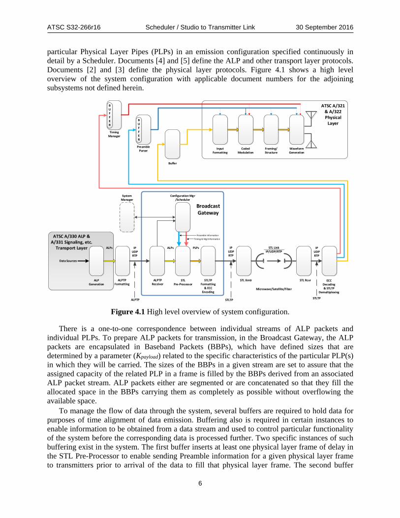
particular Physical Layer Pipes (PLPs) in an emission configuration specified continuously in detail by a Scheduler. Documents [4] and [5] define the ALP and other transport layer protocols. Documents [2] and [3] define the physical layer protocols. Figure 4.1 shows a high level overview of the system configuration with applicable document numbers for the adjoining subsystems not defined herein.
ECCDecoding& STLTP
Demultiplexing
STL RcvrSTL Xmtr
IPUDPRTP
IPUDPRTP
STLTPFormatting
& ECCEncoding
STLPre-Processor
PLPs
Configuration Mgr/Scheduler
ALPTPReceiver
ALPTPFormatting
IPUDPRTP
ALPs
ALPGeneration
ALPs
Data Sources
ALPTP STLTP
STL LinkIP/UDP/RTP
Microwave/Satellite/Fiber
ATSC A/330 ALP & A/331 Signaling, etc.
Transport Layer
SystemManager
Preamble InformationTiming & Mgt Information
STLTP
ATSC A/321 & A/322Physical
Layer
CodedModulation
InputFormatting
Framing/Structure
WaveformGeneration
Timing Manager
BUFFER
Preamble Parser
BUFFER
Buffer
BroadcastGateway
Figure 4.1 High level overview of system configuration.
There is a one-to-one correspondence between individual streams of ALP packets and individual PLPs. To prepare ALP packets for transmission, in the Broadcast Gateway, the ALP packets are encapsulated in Baseband Packets (BBPs), which have defined sizes that are determined by a parameter (Kpayload) related to the specific characteristics of the particular PLP(s) in which they will be carried. The sizes of the BBPs in a given stream are set to assure that the assigned capacity of the related PLP in a frame is filled by the BBPs derived from an associated ALP packet stream. ALP packets either are segmented or are concatenated so that they fill the allocated space in the BBPs carrying them as completely as possible without overflowing the available space.
To manage the flow of data through the system, several buffers are required to hold data for purposes of time alignment of data emission. Buffering also is required in certain instances to enable information to be obtained from a data stream and used to control particular functionality of the system before the corresponding data is processed further. Two specific instances of such buffering exist in the system. The first buffer inserts at least one physical layer frame of delay in the STL Pre-Processor to enable sending Preamble information for a given physical layer frame to transmitters prior to arrival of the data to fill that physical layer frame. The second buffer
ATSC S32-266r16 Scheduler / Studio to Transmitter Link 30 September 2016
7
accommodates a delay of up to one second to enable synchronization of frame emission timing in the Physical Layer when the delivery delay to each of the transmitters in a network is different.
Maintaining the one-to-one correspondence between particular ALP packet streams and their assigned PLPs through the system requires a method for identifying both the ALP and PLP data streams. Since the ATSC 3.0 system works in an Internet Protocol (IP) environment, IP tools and resources are used for stream identification purposes. Specifically, RTP/UDP/IP Multicast stacks are used in both of the ALPTP and STLTP structures, with specific UDP port numbers assigned to particular PLP identifiers and used in both protocols. Thus, for example, an ALP packet stream designated to be carried in PLP 07 will be carried in an ALPTP stream with a UDP port value ending in 07, and the Baseband Packet stream derived from that ALP stream and to be carried in PLP 07 will be carried within an STLTP stream with a UDP port value also ending in 07. When the emission operates in Single-PLP (SPLP) mode, all of the data to be transmitted will be carried in only a single ALP stream, and all of that data will be transmitted with the same level of robustness. If the ALP stream(s) is (are) created within the same equipment that provides the Broadcast Gateway functionality, use of the ALPTP may not be necessary.
Figure 4.1 shows a single path carrying the ALP packet stream(s) and then the PLP packet stream(s) on its (their) way(s) from the ALP Generator(s) to the transmitter(s). In reality, if there are multiple streams at any point in the system, the processing for each of the ALP packet streams and/or Baseband packet streams is applied separately to each of the streams destined for a different PLP. This separation of processes will be diagrammed using parallel paths throughout the remainder of this document, starting with the detailed examination of Figure 4.2.
To manage all of the characteristics of the emission and to coordinate all of the elements of the Physical Layer subsystem with respect to their parameter settings and times of operation, a Scheduler function is included in the Broadcast Gateway. The Scheduler manages the operation of a buffer for each ALP stream, controls the generation of BBPs destined for each PLP, and creates the signaling data transmitted in the Preamble as well as signaling data that controls creation of Bootstrap signals by the transmitter(s) and the timing of their emission. To perform its functions, the Scheduler communicates with a System Manager to receive instructions and with the source(s) of the ALP packets both to receive necessary information and to control the rate(s) of their data delivery.
One form of data relationship that the Scheduler must establish is signaling, in the Preamble of any given Physical Layer frame, the presence of Low-Level Signaling (LLS) data in specific PLPs within that frame. To enable the Scheduler to meet that requirement, upstream ALP generators in turn are required to signal to the Scheduler the presence of LLS data in specific ALP packets. When the ALPTP is used (i.e., when ALP generators and the Scheduler are in separate equipment units), such signaling takes place in the RTP header that is part of the RTP/UDP/IP Multicast stack that comprises ALPTP. This method avoids the layer violation that would occur if the Scheduler had to determine the presence of LLS by inspecting the content of the ALP packets and also covers cases in which the content of the ALP packets is not IP packets.
One of the principal functions of the Scheduler is to generate Preamble data for the transmitter(s) that it controls. Conceptually, as shown in Figure 4.2, the Preamble generation function is assigned to a Preamble Generator, which is part of the Broadcast Gateway. The Preamble Generator outputs the data to be transmitted to receivers to allow their configurations to match the processes and parameters that will be used in transmission. As the transmitter(s) process the Preamble data for emission, it also will be used to set up the Input Formatting, Coded

ATSC S32-266r16 Scheduler / Studio to Transmitter Link 30 September 2016
8
Modulation, Framing/Structure, and Waveform Generation so that the emitted waveform will match what receivers will be instructed by the Preamble to receive. The exact format for the Preamble data is specified in [3].
Similarly, the Scheduler must control the generation and emission of Bootstrap waveforms by the transmitter(s). To accomplish this, a data structure, similar to the Preamble, is defined in this document to carry Timing and Management data to the transmitters. Conceptually, as shown in Figure 4.2, a Timing and Management Data Generator is included in the Broadcast Gateway and provides the function under control of the Scheduler.
BBP data are carried across the STL as an RTP/UDP/IP Multicast stream for each PLP. These streams are multiplexed into a single RTP/UDP/IP Multicast stream for each broadcast emission to enable reliable delivery to the transmitter(s) of correctly identified and ordered BBPs. Conceptually, the BBP data streams, as well as the Preamble stream and Timing and Management stream, are encapsulated as an inner stream carried through the outer stream formed by the STLTP. Both use IP multicast. The inner stream provides addressing of BBP streams to their respective PLPs through use of UDP port numbers. The outer protocol, STLTP, provides maintenance of packet order through use of RTP header packet sequence numbering. The STLTP also enables use of (SMPTE 2022-1) ECC to maintain reliability of stream delivery under conditions of imperfectly reliable STL networks.
At the transmitter(s), an input buffer is used for each PLP to hold BBP data until it is needed for transmission. There also are FIFO buffers for the Preamble stream and the Timing and Management stream. The Preamble stream processing includes a Preamble Parser that collects all of the configuration information for the next and possibly several upcoming Physical Layer frames to use in configuring the transmitter data processing for those frames.
Preamble data is scheduled to arrive at the transmitter input at least one full physical layer frame period prior to the last byte of the associated payload to provide time for the transmitter data processing to be properly configured. Preamble data also can be sent multiple times in advance to enable acquisition of the data with improved reliability. The same considerations also are applicable to the Timing and Management data; i.e., it is scheduled to arrive at the transmitter input at least one physical layer frame period prior to the last byte of the associated payload (+processing delay) it describes, and it can be sent multiple times to enable improved reliability of its acquisition.
4.2 Detailed System Architecture The Studio to Transmitter Link (STL) interface is typically located between the baseband framer and the Forward Error Correction (FEC) block. There only needs to be one scheduler and one baseband framer per RF emission. Multiplexing of multiple Services among stations on one RF emission can be accommodated on the input side of the Scheduler.

ATSC S32-266r16 Scheduler / Studio to Transmitter Link 30 September 2016
9
Bit Int’lFEC Mapper LDM MIMO Time Int’l OFDM Framer/
Preamble Inserter
Freq Int’l Pilot/Tone
Reserve
MISO IFFT PAPR GI Bootstrap/Spectrum Shaping
D/A
≤1sec
NetworkComp.Buffers
Preamble Parser
PLPs PLPs PLPs PLPs
Timing Manager
BUFFER
BUFFER
PLPs PLPs PLPs
GNSS Time
PHYFr
PHYFr
PHYFr
PHYFr
PHYFr
PHYFr
PHYFr
PHYFr
TAD
PLP DemuxSMPTEST 2022-1
ECCDecoder
SMPTEST 2022-1
ECCEncoder
PLP Mux STL RcvrSTL Xmtr
IPUDPRTP
IPUDPRTP
IPUDPRTP
IPUDPRTP
IP Packetizers
BasebandPacketizers
PLPsPLPs
Scheduler
Timing & MgtDataGenerator
PreambleData
Generator
ALPDemux
ALPMux
IPUDPRTP
ALPs
ALPEncapsulation
ALPs
Data Source
Data Source
Data Source
Data Source
Scrambler
PLPs
ALPPayload(ALPTP)
BBPPayload(STLTP)
IP (ROUTE/MMT),TS, Generic Data
Payloads
From/To System Manager(BXF)
To/FromData Sources
(MDCoIP)
STL LinkIP/UDP/RTP
Microwave/Satellite/Fiber
ALP Packets
Baseband Packets
Preamble Data Packets
Timing Data Packets
Timing Data
Preamble Data
Timing Instructions
Configuration Instructions
Emission-Formatted Preamble Data
Legend
1 PhyFrameDelay
(≤5secs)
ALPBuffers
ALPs
LLS Ind.
ConfigurationMgr
BBPPayload(STLTP)
EAS Trig.
BroadcastGateway
Figure 4.2 System architecture.
Figure 4.2 shows a possible system architecture, other configurations are possible. When considering configurations, data rates and interfaces between function blocks need to be factored in for practical implementations. 4.2.1 System Manager Configuration aspects are controlled from one entity called the System Manager. This entity provides configuration parameters for the various system functions for example video encoders to operate at fixed QP or constant bit rate and to define the physical layer configuration for the Scheduler. 4.2.2 Scheduler The Scheduler takes an input of ALP packets as defined in [5] and directs how these packets are allocated to physical layer resources. Specifically, the Scheduler directs via control information how the baseband framing block will output baseband packets, arranged as physical layer pipes (PLPs). A notional system architecture including the Scheduler is shown in Figure 4.2. The operation of the Scheduler is constrained by a system buffer model and the limitations imposed on the defined Services operating on the specified PLPs within the available bandwidth.
The inputs to the Scheduler include ALP packets with their associated delivery metadata. The System Manager defines system configuration, for example the number and configuration of PLPs and their constraints for example the maximum capacity assignable to each PLP. These constraints are fed to the Scheduler.
The output of the Scheduler defines specifics of the baseband framing of the data packets. The input combination of data and delivery metadata is converted into a description of physical

ATSC S32-266r16 Scheduler / Studio to Transmitter Link 30 September 2016
10
layer configuration that controls which data is sent at which times via specific physical layer resources. 4.2.3 Studio to Transmitter(s) Dataflow The studio to transmitter link (STL) may operate on any of fiber, satellite or microwave links. STL redundancy is possible, but is out of scope for this document. Internet Protocol (IP) is supported on all link types. 4.2.4 Transmitter Operation
4.2.4.1 System Manager Control The System Manager controls static or quasi static configurations of the transmission chain. It controls the physical layer configuration with respect to how many PLPs operate and the configurations of the individual PLPs, the Services supplied on those PLPs, and the delivery sessions that support the Services that run in the PLPs. There could be a pre-determined schedule for service operation, the system manager can be responsible for implementing it. 4.2.5 STL / SFN Operation Broadcasters have a need to send studio generated data to their transmitters. Usually those transmitters are not co-located at the studio. An STL interface from the studio to the transmitter(s) is needed. That interface is required to:
1) Support Internet Protocol / User Datagram Protocol (UDP/IP) IPv4 and addressing 2) Encapsulate data for the link 3) Provide a synchronization method to ATSC time for data and control 4) Provide signaling of the transmitter timing synchronization for data and control 5) Have defined maximum latency, so as to allow the emission time to be correct 6) Allow for redundancy
4.3 Central Concepts ALPTP The ALPTP protocol provides a solution for transferring ATSC Link Layer [5] Packets through a typical IP network between two disparate devices as shown in Figure 4.2. ALP packets are fairly simple constructs with a minimal header and packet length information sufficient for an emission link layer. These headers are not sufficient for transferring ALP packets through a typical IP network so the ALPTP is defined to provide this additional networking information. Additionally, ALP packets must be kept in order for each PLP. There is a single ALP stream associated with each PLP so unique IP port is defined for each ALPTP packet stream. 4.3.1 IP Multicast All packets delivered over the ALPTP link shall use a UDP/IP Multicast IPv4 protocol. Real-time Transport Protocol (RTP) protocol is used with its headers as redefined in Section 6.3. Segmentation and reassembly of large ALP packets and concatenation of small ALP packets is performed with RTP. RTP also provides capabilities for ordering packets as well as framing, that is, identifying where each ALP packet starts within the RTP/UDP/IP payload stream. 4.3.2 Address Assignments IPv4 packet format and addressing are used exclusively on the ALPTP link. The ALPTP stream shall be broadcast using a multicast address in the range 239.0.0.0 through 239.255.255.255 which is within the Organization Local Scope range defined by IETF.

ATSC S32-266r16 Scheduler / Studio to Transmitter Link 30 September 2016
11
4.3.3 Port Assignments Each multicast destination address has 1 – 65535 usable port numbers. IP port numbers 30000 through 30063 shall be used corresponding to PLP 1 through 64, respectively. All packets have defined port numbers within a single IP address. Packet types are described in section 6.3.
4.4 Central Concepts of STLTP 4.4.1 IP Protocol Stack IP structure enables use of STLTP across STL IP links. There are IP packets of three types.
1) Payload data packets that populate PLPs and are transmitted to all transmitters 2) Preamble data packets derived from scheduling outcome to populate preambles, define
exciter configurations 3) Timing data packets to coordinate synchronization among transmitters and control
bootstrap emission timing and frame identification. 4.4.2 IP multicast All packets delivered over the STL link shall use a UDP/IP Multicast IPv4 protocol.
Real-time Transport Protocol (RTP) protocol is used with its headers as redefined in Section 6.2. Segmentation and reassembly of large payload packets and concatenation of small payload packets is performed with RTP. A value for number of segments within RTP/UDP/IP headers and segment sequence numbers within an RTP/UDP/IP header allow for segmentation and reassembly. The number of RTP/UDP/IP headers within an IP packet allows for concatenation. Only a single category of RTP/UDP/IP headers can be concatenated within a single IP packet. 4.4.3 Address assignments IPv4 packet format and addressing are used exclusively on the STL link. The multicast (destination) address range is 224.0.0.0 – 239.255.255.255. Of that range, 239.0.0.0 – 239.255.255.255 are for private addresses. 4.4.4 Port Assignments Each multicast destination address has 1 – 65535 usable port numbers. Values of 30000 – 30065 inclusive are used for this standard.
All packets have defined port numbers within a single IP address. Packet types are described in sections 6.2, 6.3 and 6.4. Internal headers within the IP packets enable segmentation and reassembly of large payload packets, and concatenation of small payload packets. 4.4.5 Error Control Coding Scheme Error Correction Coding (ECC) is provided for STL data, preamble, and timing information sent to each transmitter. SMPTE 2022-1 [8] provides the STL ECC and is intended for data rates up to around 1 Gbps, making it appropriate for the STL.
4.5 System Time Domains Figure 1.1 above depicts a Studio Interface into and an STL Interface out of the Broadcast Gateway. The format of time expression on these two interfaces is different. The use of the two different formats derives from system layering. Media timing in the system is according to NTP [15]. The short format of NTP is 16 bits representing seconds and 16 bits representing fractions of a second in Coordinated Universal Time (UTC) [16]. UTC contains leap seconds.
ATSC S32-266r16 Scheduler / Studio to Transmitter Link 30 September 2016
12
The description of time on the STL interface (STLTP) is the based on International Atomic Time (TAI), which does not contain leap seconds [17]. Time description on this interface uses 32 bits to represent seconds and 32 bits to represent nsecs [13].
ATSC Physical Layer Time which is defined by 32 lsb bits of TAI seconds and BCD coded msecs, usecs, and nsecs is delivered to a receiver in the preamble [3]. The 16 bits required to complete TAI 48 bit seconds are carried in the System Time fragment [4].
4.6 System Manager Configuration Interface TBD
4.7 Real Time Control Interface TBD
4.8 SFN Operation TBD
4.9 Bonded-Channel Operation TBD
4.10 Receiver Assumptions? TBD
5. SCHEDULER DESCRIPTION AND NORMATIVE REQUIREMENTS
5.1 Relationship of Broadcast Gateway and Scheduler to the System Figure 5.1 below shows a conceptual block diagram of the Broadcast Gateway with its associated interfaces. The Configuration Interface allows provision of quasi-static aspects such as PLP definitions. The Studio Interface delivers content and signaling, this content and signaling subject to delivery metadata. The Scheduler can communicate control upstream on the Studio Interface via ALPTP. The SFN Interface communicates a complete description of a physical layer instance on a frame by frame basis to an SFN of transmitters. Multiple RF Channel Service may require the synchronization of two Broadcast Gateways as depicted in Figure 5.2

ATSC S32-266r16 Scheduler / Studio to Transmitter Link 30 September 2016
13
Broadcast Gateway
Quasi-static Configuration
DeliveryMetadata
Content and Signaling
StudioInterface
SFNInterface
ConfigurationInterface
Scheduler
ALP TPTransceiver
PerPLP
Buffer
SFN TPSenderBaseband
Packet
BootstrapGenerator
PreambleGenerator
MuxTime
Schedule
Select
Figure 5.1 A Broadcast Gateway conceptual diagram.

ATSC S32-266r16 Scheduler / Studio to Transmitter Link 30 September 2016
14
Broadcast Gateway 1
Quasi-static Configuration
DeliveryMetadata
Content and Signaling
StudioInterface
SFNInterface
Configuration Interface (BXF)
Scheduler
ALP TPTransceiver
PerPLP
Buffer
SFN TPSenderBaseband
Packet
BootstrapGenerator
PreambleGenerator
Mux
Time
Select
Real Time Control
(MDCoIP)
BroadcastGateway 2
StudioInterface
SFNInterface
Scheduler
ALP TPTransceiver
PerPLP
Buffer
SFN TPSenderBaseband
Packet
BootstrapGenerator
PreambleGenerator
MuxTime
Select
Schedule
Schedule
Common TimeSource
CommonConfiguration
CommonAnalyzed Media
Duration
Real Time Control
(MDCoIP)
Frame Sync
Figure 5.2 Synchronization of multiple Broadcast Gateways.
5.2 Scheduler Function The functional assets of the Scheduler are defined by data size(s) and time(s) on the physical layer. The physical layer can deliver defined quantities of data at certain discrete times. The Scheduler receives the following inputs and information:
1) ALP Encapsulated Baseband Data Packets 2) Delivery Metadata for the encapsulated Baseband Data Packets 3) A System Buffer Model [4] 4) Constraints and Configuration instructions from the System Manager From these inputs, it creates an efficient allocation of the physical layer resources
conforming to the configuration and constraint instructions from the System Manager. This solution is subject to both the configuration and control parameters and the aggregate spectrum available. The Scheduler manages buffer fullness throughout the transmitter chain based on maximum delay of the network, maximum sizes of subframes / Frames and using STL channel bandwidth allocation to IP port streams which also requires determination of packet ordering in STL. The Scheduler must be aware of timing throughout the transmitter chain and determine bootstrap emission times, create timed control data for all transmitters (collectively and

ATSC S32-266r16 Scheduler / Studio to Transmitter Link 30 September 2016
15
individually) and pass timing and management control data to the Timing and Management Data Generator so that it can create Timing and Management Data Packets that are sent to the transmitter(s).
The Scheduler defines physical layer frame lengths, subframe sizes, and bootstrap emission times; assigns frame identifiers based on bootstrap emission times; determines waveform configurations for frames; creates preambles according to physical frame configurations; manages baseband packet creation and ordering; and manages packet identification.
For VBR encoding, there may be two feedback loops that the scheduler is a part of: a short-time-frame feedback loop which controls the video / audio encoded bit rates on a per physical layer frame basis, and a slower configuration (control) loop. The slower loop may also contain data for Services that are subject to quasi static rate control and that adapt more slowly, for example, NRT. This class of service may have entry control to utilize as much bandwidth as is opportunistically available, but not less than X (although X might vary according to a macro-schedule subject to NRT queue depth). There may also be Services that have static assigned rates and are not subject to dynamic management other than turning the Service on or off. The order of assignment of static allocation of physical layer resources can be controlled by delivery metadata.
It is not expected that a PLP will be dynamically reconfigured with respect to its data processing characteristics. If a PLP is to transition from one configuration to another, the set of PLP characteristics will have an explicit schedule. For example, a PLP may run in configuration XYZ for a period of 12 hours, then run on PLP configuration JKL for the following 12 hours, and repeat daily. From the Scheduler’s perspective, it may schedule encapsulated Baseband Packets in either period, but not across the boundary. Conceptually, a PLP configuration that changes at certain times could be obtained by utilizing two separate PLPs, one of which, during any given physical layer frame, has 0 traffic bandwidth assigned to it.
The practical consequence of the previous paragraph is that a FEC Frame and/or an interleaver never operates in a fractional sense. There are no partial FEC frames. There can be FEC Frames for convolutional interleaving (hybrid interleaving) which span the bootstrap and preamble. Note that operationally, it may make sense to set up all traffic PLPs that can exist and only populate those that are currently allowed to carry traffic. This is only a notional example. This is not a requirement.
5.3 Scheduler Input Ports A list of scheduler ports is provided in Table 5.1.

ATSC S32-266r16 Scheduler / Studio to Transmitter Link 30 September 2016
16
Table 5.1 Scheduler Ports Parameters System Manager
Configured (Scheduler Input) Section 5.3.1
Scheduler Controlled (Scheduler Generated) Section 5.3.2
Per F
ram
e D
ata
Channel bandwidth Sampling Frequency Major and Minor version values Frame length Frame alignment Frame PAPR CRC values (L1B) CRC values (L1D) Preamble NoC FEC Mode for L1-Detail Additional parity for next frame Channel ID’s involved in channel bonding Center frequency of channels involved in bonding LLS flag Time info flag
Per S
ubfra
me
Dat
a
Subframe size Subframe MIMO/MISO/SISO Subframe FFT sizes Subframe NoC Subframe GI Subframe pilot pattern Subframe pilot boost Subframe boundary symbols flags Subframe FI mode
Per P
LP D
ata
PLP ID’s PLP sizes PLP LLS flag PLP scrambler type PLP FEC modes PLP LDPC rate PLP modulation PLP time interleaver mode PLP CTI depth PLP CTI start row PLP CTI position of first complete FEC frame PLP HTI inter-subframe interleaving flag PLP HTI number of TI blocks or subframes PLP HTI max interleaving FEC blocks per interleaving frame PLP HTI number of FEC block in the current interleaving frame PLP cell interleaver flag PLP LDM layer PLP injection level

ATSC S32-266r16 Scheduler / Studio to Transmitter Link 30 September 2016
17
PLP Channel ID’s involved in channel bonding PLP Center frequency of channels involved in bonding
5.3.1 Scheduler Management Port The interface between the Scheduler and System Management functions shall use SMPTE Broadcast Exchange Format protocol as described in [10].
The parameters using this protocol are those listed in Table 5.1 under the parameter column with a check mark in the System Mgr. Configured column. These parameters are quasi-static in nature and do not routinely change between physical layer frames. Scheduler configuration and constraints are set with these parameters which are allowed to quasi-statically change. An emission schedule for a set of parameters can be similar to a program schedule where they can change over the course of a day. Detailed description of these parameters is provided in Annex A.
The System Management function identifies: 1) Source IP address of each ALP stream (number of ALP streams = number of PLPs) 2) PLP identification for each ALP stream 3) Control IP address for each ALP stream (number of control points = number of PLPs) System Management function to Scheduler messages include • Capabilities inquiry • Configuration design inquiry (establish response from Scheduler as a preset) • Current configuration inquiry • System Setup instructions • Scheduled configuration instructions (possibility for preset values) Scheduler feedback to the System Management function indicates the physical layer
capabilities and the structure details for each requested frame type. Scheduler to System Management function messages include
• Capabilities response • Configuration design response (acknowledgement of preset instructions) • Current configuration response • System setup acknowledgement • Scheduled configuration acknowledgement
5.3.2 Scheduler Control Port The interface between the Scheduler and data source controls shall use SMPTE Media Device Control protocol as described in [11].
The parameters using this protocol are those listed in Table 5.1 under the parameter column with a check mark in the Scheduler Controlled column. These parameters are dynamic in nature and do routinely change between physical layer frames. A Scheduler configures the data sources with these parameters on a real time basis. Detailed description of these parameters is provided in Annex A.
Scheduler informs data sources of target bit rate ranges and can throttle those data sources to maintain PLP capacities. These real time control parameters are sent to the data source IP address as specified from the System Management function. Data sources can be multiplexers, encoders, servers, etc.
Messages between these data sources and the Scheduler can include

ATSC S32-266r16 Scheduler / Studio to Transmitter Link 30 September 2016
18
• Capabilities inquiry • Request for capacity from the data source • Target bit range instructions from the scheduler As for bit rates, there can be a variety of settings like bit ranges covered by PLP variability or
specified target bit rates not to be exceeded. Either way, bit rates are expressed to 1 bit/sec accuracy.
5.4 Scheduler Operation The operation of the Scheduler is constrained by combination of dynamic, quasi-static, and static parameters. The exact definition of these constraints is left to implementation. This document defines a required function, but not the parameters of that function.
There are two categories of metadata associated with content to be delivered. There is metadata associated with the content which must transit the link as they comprise information needed to successfully decode and render the media. There is another class of metadata which is exclusive to the task of scheduling media on ATSC 3.0 system. This scheduling metadata is referred to as delivery metadata. This section largely discusses the functions and application of this delivery metadata. There is some discussion with respect to the order in which metadata and content should be delivered in order to optimize channel change speed.
The cascade of functions involved in the process of scheduling are shown below in Figure 5.3. This figure contains no requirements it is merely an example of an architecture. References to time are with respect to Server Current Time (SCT) as discussed in [4].
Encoder(s)NAL
Segmenter(s)ISO BMFF and DASH
Sender(s)IP/UDP/ROUTE Scheduler
with Buffer Model(s)
WaveformDescriptionGenerator
and Encapsulator
Media AwareByte Ranges
ALPEncapsulator
Media AwareByte Ranges in
ROUTE
Media AwareByte Ranges
in ALP
STL TP
ExciterTransmitter
Antenna
Delivery MetadataMedia/Metadata
TransmitterSites
Legend
Rate Adaptation
Signaling / NRT
Delivery Metadata
Media AwareByte Ranges in Baseband
Packets
Media in NALReal Time Control
Figure 5.3 Cascade of real time functions involved with Scheduler.
Figure 5.4 below shows an example conceptual depiction of process of the scheduler process flow. The central concept being there are durations of time under construction with known target radiation times. The process generates an endless sequence of Media Segments, which are mapped into physical layer frames and transmitted. There are no requirements contained in this figure. The figure is merely an example. The point of the figure is there is a process in time which results in Media Segments being constructed and radiated. The construction of said Media Segments and physical layer frames is series of intermediate processes that each run on a deadline. For the purposes of this figure, there is one Media Segment per Service per physical

ATSC S32-266r16 Scheduler / Studio to Transmitter Link 30 September 2016
19
layer frame. This is not required and may not be optimum. This figure is depicted with a one to one correspondence among Media Segments and physical layer frames as a convenience to illustrating the process flow in time. The relationship between an analyzed media duration and physical layer frames is discussed in some detail in Section 5.4.5.
Segment N+2 Assign to FEC Frame(s)
Target Segment N+3 (Fails to Schedule)
Media for Target Segment N+4
Segment N+1 Delivery in STL TP
(Re) Encode Target Segment N+3
Media Encoders
Segmenter /Encapsulators
(ROUTE/IP/ALP)
Scheduler
Transmitters Segment N Delivery in ATSC 3.0 Phy
DiscardFailed
Encode
STL
Re-e
ncod
ePa
ram
eter
s
Delivery Metadata
Delivery Metadata
During Phy Frame M -3
During Phy Frame M
During Phy Frame M -2
During Phy Frame M -1
During Phy Frame M -4
Figure 5.4 Example depiction of a high level scheduler process flow.
5.4.1 Key Concepts Scheduler Delivery Metadata The concept of earliest delivery at the physical layer is illustrated in Figure 5.5 below. The data contained in this FEC Frame will radiate from the ATSC 3.0 transmitter after this Earliest Time. As shown, this description is inclusive of all processes comprised in the generation of the transmitted FEC Frame. If the FEC Frame were being discussed in the context of the Sync and Delivery [4] the physical layer FEC Frame contains data that is a Data Delivery Event at the receiver.
Latest Time at the physical layer is illustrated in Figure 5.5 below. Conceptually, this is constructed and constrained in a manner similar to Earliest Time above. The data contained in this FEC Frame will radiate from the ATSC 3.0 transmitter before this Latest Time.

ATSC S32-266r16 Scheduler / Studio to Transmitter Link 30 September 2016
20
2kB or
8kB
2kB or
8kB
2kB or
8kB
Time at
Rate
FEC Frame 2kB or 8kB
FEC Frame 2kB or 8kB
FEC Frame 2kB or 8kB
Time at
Rate Time Interleaver Depth in Time
Late
st T
ime
at th
e Ph
y
Earli
est T
ime
at th
e Ph
y
…..…..
Pre-Time Interleaver FEC FramesPost Time Interleaver FEC Frames Figure 5.5 Illustration of earliest and latest time with a block interleaver.
Figure 5.5 is depicting the Earliest and Latest time of a FEC Frame as realized in the physical layer. In practice the Scheduler function should receive a notably wider time range of Delivery metadata, such that the Scheduler is not over constrained.
Figure 5.6 provides a conceptual view of earliest and latest in the context of a Media Segment playback duration. Figure 5.6 depicts a broader notion of earliest and latest for multiple use cases.
Allowed Range of Send Time of Segment Data
Media Segment Run Time Duration
Late
st T
ime
at th
e Ph
y
Earli
est T
ime
at th
e Ph
y
Allowed Range of Send Time of Segment Data
Allowed Range of Send Time of Segment Data Media Segment Run Time Duration
Late
st T
ime
at th
e Ph
y
Earli
est T
ime
at th
e Ph
y
Media Segment Run Time Duration
Late
st T
ime
at th
e Ph
y
Earli
est T
ime
at th
e Ph
y
Figure 5.6 Illustration of Earliest and Latest Time options relative to Media
Segment play.
ATSC S32-266r16 Scheduler / Studio to Transmitter Link 30 September 2016
21
These use cases are intended to illustrate that the concept of earliest and latest is flexible and that while time at the physical layer is related to Media Segment. These use cases are not requirements. The three use cases depict that the mechanism can describe a variety of implementations. In the top use case, the specification of early would allow the Scheduler to send Media Segment data significantly ahead of the actual demand time for the start of playback. The Late Time in this example is bounded by the playback deadline for the Media Segment. The time shown is a duration not the actual delivery or play time. The middle use case depicts a situation where the media playback and media delivery is constrained to be within a Media Segment playback duration. This might be required, for example if there is any switching among PLPs, for example at a DASH Period boundary. The bottom use case illustrates a use case in which the delivery of a Media Segment is accomplished in less than a Media Segment run time duration. This sort of use case can result in faster channel change. These use cases are merely examples and not intended to constrain the definition or usage of earliest and latest or actual implementation.
LCTPacket
LCTPacket
LCTPacket
LCTPacket
LCTPacket
LCTPacket
MDE Data Block (Byte Range) Late
st T
ime
at th
e Ph
y
Earli
est T
ime
at th
e Ph
y
I
B3
B3
B3
B3
P
B2
B1
B2
I
B3
B3
B3
B2
B1
B2
B3
B3
B3
P
B2
B1
B2
B3
B3
0/24 1/24 3/24
PB1B2B3
B3B3B2B3
PB1B2B3
9/24 11/24
B3B3B2B3
B1B2B3
17/24 19/24
B3B3B2B3
DemandTime
Relative to 1 Second
MediaDeliveryEvents
MDE MDE MDE MDE MDE MDEMDE
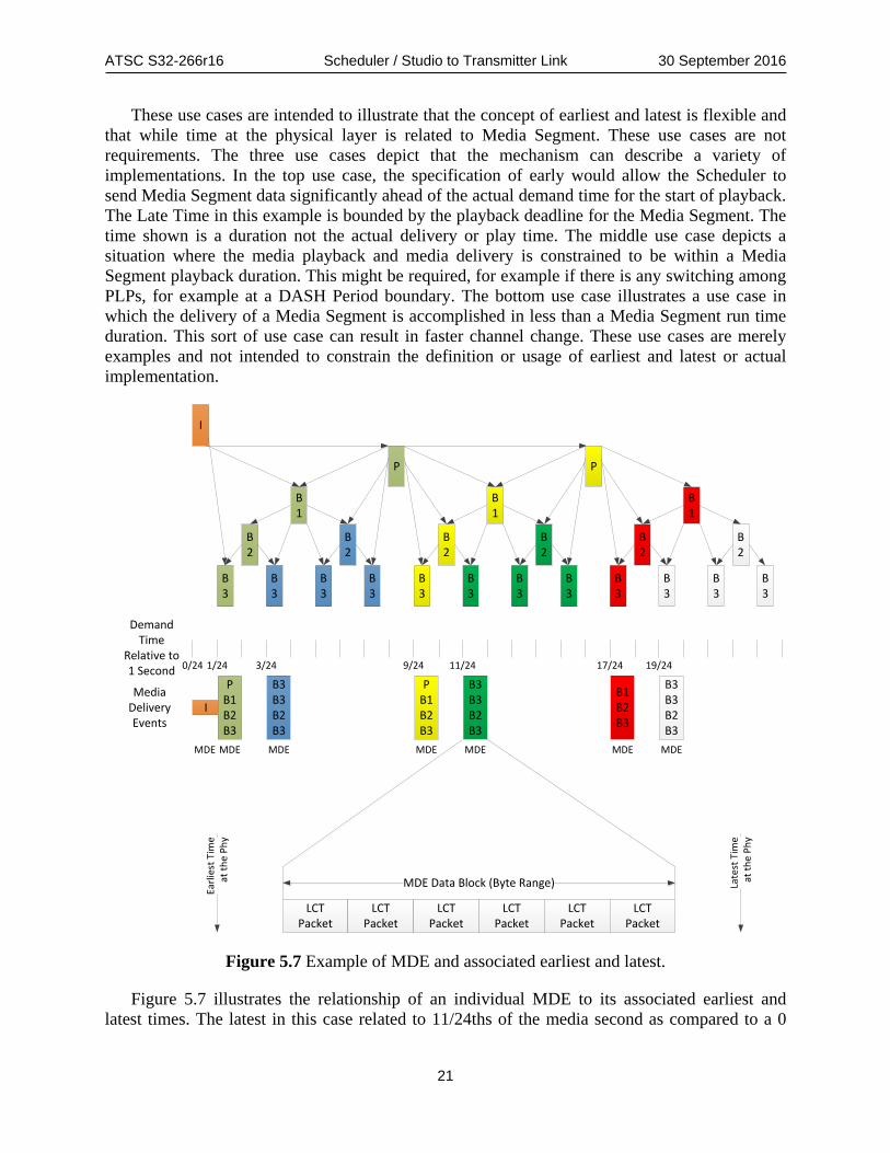
Figure 5.7 Example of MDE and associated earliest and latest.
Figure 5.7 illustrates the relationship of an individual MDE to its associated earliest and latest times. The latest in this case related to 11/24ths of the media second as compared to a 0

ATSC S32-266r16 Scheduler / Studio to Transmitter Link 30 September 2016
22
latest time for the I frame MDE of the same “GoP.” The 0 late time is repeating in this example on 1 second boundaries. If in this example, the physical layer frame and Media Segment boundaries are conformed to whole seconds, Earliest Time could be N.0000 and Latest Time N.99999. Given that in order delivery is enforced for streaming media the functional requirement is within this whole second for Segment delivery.
LCTPacket
LCTPacket
LCTPacket
LCTPacket
LCTPacket
LCTPacket
MDE Data Block (Byte Range) Late
st T
ime
at th
e Ph
y
Earli
est T
ime
at th
e Ph
y
LCTPacket
LCTPacket
LCTPacket
LCTPacket
LCTPacket
LCTPacket
MDE Data Block (Byte Range) in IP
Late
st T
ime
at th
e Ph
y
Earli
est T
ime
at th
e Ph
y
IP Header
IP Header
IP Header
IP Header
IP Header
IP Header
Figure 5.8 Relationship of an MDE in LCT packets to IP encapsulation.
In Figure 5.8 an example of an MDE with IP encapsulation is shown. This figure contains no requirements beyond the Earliest and Latest Times being inherited from the MDE. There is no requirement that there is one LCT packet per IP header. There is no requirement that there is more or less than one LCT packet per IP Header. The only requirement is that IP packets containing the MDE are subject to the earliest and latest requirements of the source MDE data block. 5.4.2 Handling Boundary Conditions To this point these concepts have been discussed in broad terms. Known metadata about the timeline of the encapsulated and to be encapsulated media is expressed down stack to the Scheduler. This process may be summarized as the encapsulated media inherits the delivery requirements of contained media. There are assorted boundary conditions to consider. This section illustrates a few of these and describes how delivery metadata may be handled.
ATSC S32-266r16 Scheduler / Studio to Transmitter Link 30 September 2016
23
Earli
est T
ime
at th
e Ph
y
Late
st T
ime
at th
e Ph
y
LCTPacket
LCTPacket
LCTPacket
LCTPacket
LCTPacket
LCTPacket
MDE Data Block (Byte Range) in IP
Late
st T
ime
at th
e Ph
y
Earli
est T
ime
at th
e Ph
y
IP Header
IP Header
IP Header
IP Header
IP Header
IP Header
FEC Frame FEC Frame FEC FrameFEC Frame FEC FrameFEC Frame
LCTPacket
IP Header
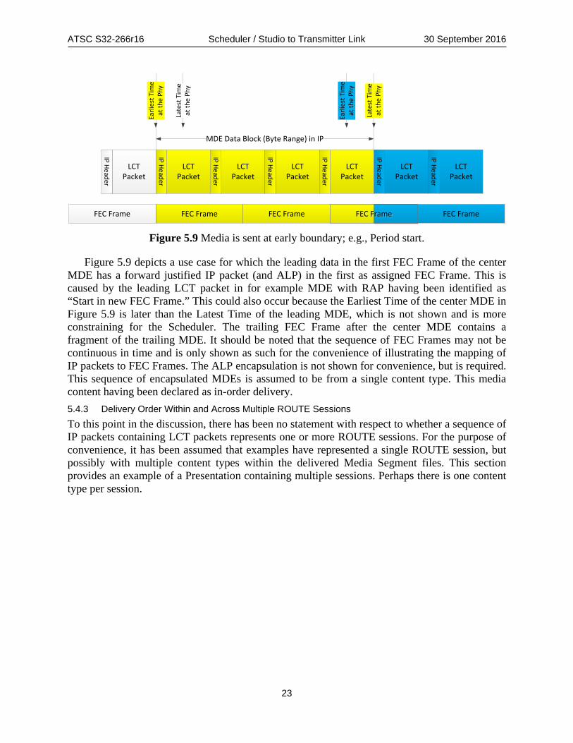
Figure 5.9 Media is sent at early boundary; e.g., Period start.
Figure 5.9 depicts a use case for which the leading data in the first FEC Frame of the center MDE has a forward justified IP packet (and ALP) in the first as assigned FEC Frame. This is caused by the leading LCT packet in for example MDE with RAP having been identified as “Start in new FEC Frame.” This could also occur because the Earliest Time of the center MDE in Figure 5.9 is later than the Latest Time of the leading MDE, which is not shown and is more constraining for the Scheduler. The trailing FEC Frame after the center MDE contains a fragment of the trailing MDE. It should be noted that the sequence of FEC Frames may not be continuous in time and is only shown as such for the convenience of illustrating the mapping of IP packets to FEC Frames. The ALP encapsulation is not shown for convenience, but is required. This sequence of encapsulated MDEs is assumed to be from a single content type. This media content having been declared as in-order delivery. 5.4.3 Delivery Order Within and Across Multiple ROUTE Sessions To this point in the discussion, there has been no statement with respect to whether a sequence of IP packets containing LCT packets represents one or more ROUTE sessions. For the purpose of convenience, it has been assumed that examples have represented a single ROUTE session, but possibly with multiple content types within the delivered Media Segment files. This section provides an example of a Presentation containing multiple sessions. Perhaps there is one content type per session.

ATSC S32-266r16 Scheduler / Studio to Transmitter Link 30 September 2016
24
Earli
est T
ime
at th
e Ph
yEa
rlies
t Tim
eat
the
Phy
Late
st T
ime
at th
e Ph
y
Late
st T
ime
at th
e Ph
y
Earli
est T
ime
at th
e Ph
y
LCTPacket
LCTPacket
MDE Data Block Which Contains T-RAP in IP
IP Header
IP Header
Video
AudioLCT
Packet
IP Header
LCTPacket
IP Header Late
st T
ime
at th
e Ph
y
Closed Caption
LCTPacket
LCTPacket
IP Header
IP Header
Trailing MDE
Video T-RAP Holdoff Time
Audio T-RAP Holdoff Time
Closed Caption T-RAP Holdoff Time
Late
st T
ime
at th
e Ph
y
LCTPacket
IP Header
...
...
Figure 5.10 Example of ordered delivery across multiple sessions.
In Figure 5.10 an example is shown of delivery of multiple sessions across a single or multiple PLPs. In this example the MPD is delivered in the T-RAP of video and the DASH client will see and request byte range delivery ahead of Media Segment availability start time. The video typically has the longest RAP cadence, so it is best to align MPD delivery to the video RAP. A key requirement for MDE is request of byte range delivery ahead of Media Segment availability start time. The ROUTE MDE hold off time due to EXT_ROUTE_PRESENTATION_TIME - SCT will expire ahead of Media Segment availability start time and this can be understood via @availabilityTimeOffset in the MPD.
MDE Data Block Which Contains T-RAP in IP
Video Audio Closed Caption
Trailing MDEVideo T-RAP Holdoff Time
Closed Caption T-RAPHoldoff Time
Audio T-RAP Holdoff Time
LCTPacket
IP Header
LCTPacket
IP Header
LCTPacket
IP Header
LCTPacket
IP Header
LCTPacket
IP Header
LCTPacket
IP Header
LCTPacket
IP Header
......
Earli
est T
ime
at th
e Ph
y
Late
st T
ime
at th
e Ph
y
Late
st T
ime
at th
e Ph
y
Earli
est T
ime
at th
e Ph
y
Earli
est T
ime
at th
e Ph
y
Late
st T
ime
at th
e Ph
y
Earli
est T
ime
at th
e Ph
y
Late
st T
ime
at th
e Ph
y
Figure 5.11 Explicit delivery order on PLP with multiple sessions.

ATSC S32-266r16 Scheduler / Studio to Transmitter Link 30 September 2016
25
The order of the to be delivered IP packets may be preserved in a PLP. This is shown in Figure 5.11. This is not relevant for a service spanning multiple PLPs. This requires that the sequence of LCT packets in IP or compressed IP is preserved in the emission. None of the timing description changes, but the PLP mapper is configured to observe in-order delivery of the IP stream as delivered to a specific PLP at the Scheduler. 5.4.4 Timelines and Deadlines The delivery of media as ISO BMFF files is an essentially endlessly repeating loop. Each Media Segment of media in Live streaming is expressed in an ISO BMFF container that has an internal time line that starts at 0 and repeats on a for example N second interval. A DASH MPD has a defined presentation timeline for the ISO BMFF files and the relationship of the send times at the physical layer has a nominally static relationship. The MDE method is adaptive to the stack delay of the receiver i.e. it starts as soon as possible without a stall. In each case, the correct timing must be defined by the Segmenter and ROUTE encapsulator respectively.
If all the video “GoPs” run on the same time cycle i.e. the I frames across Services align in time, most of the benefit of MDE mode will likely accrue to no time guard banding being required for stack delay variability. For Media Segment playback, the MPD must work for the slowest stack. MDE playback starts as soon after receipt of a T-RAP as allowed. In order to achieve faster start up the use of staggered Media Segment start times is likely required and non-uniform bandwidth assignment priority vs. time. These are implementation details, which do not change the fundamental mechanisms i.e. each MDE and Media Segment have a time deadline for delivery at the physical layer expressed by a Latest Time. 5.4.5 Concept and Practice of Analyzed Media Duration The discussion up to this point has assumed that media is being encoded based on a one second Media Segment duration, while this is conceptually convenient it is a bit simplistic as compared to the capabilities of ATSC 3.0. The generalized construct for creating physical layer frames is an Analyzed Media Duration. As discussed above the delivery on the physical layer must meet a set of requirements driven by media time line(s). The physical layer frames defined by the Scheduler do not have to correspond precisely to the Media Segment durations, as long as the time delivery requirements are met. The boundaries of physical layer frames may not or do not directly correspond to Media Segments, but they are related. The next paragraphs describe how the general method may be applied.
For each ALP stream input, there is a data source. Video data sources can be the most demanding in terms of ISO BMFF media segment file size and therefore can drive requirements for ALP buffer size and Analyzed Media Duration. Large encoded media segment files may or may not be represented as MDE. An Analyzed Media Duration is a period of time that is sufficient across all ALP streams provided to the Scheduler such that an analysis period is not dependent on other scheduling periods. See Figure 5.12 as an exemplary illustration of IDR positions and how the ALP buffer may go to zero (empty) at the end of each media segment. If it does not go empty, it is because a portion of the next Media Segment is already present. This description is valid for media segment(s) delivery, irrespective of the ISO BMFF file delivery method for those media segments.
ATSC S32-266r16 Scheduler / Studio to Transmitter Link 30 September 2016
26
1.5 Sec. Segment 1.5 Sec. Segment
1 Sec. 1 Sec. 1 Sec.1 Sec. 1 Sec.
1.5 Sec. Segment 1.5 Sec. Segment
1 Sec. 2 Sec. Segment
3 Sec. Segment Buffer may go to zero
Analyzed Media Duration
ConstrainingMedia Segment
5 Sec. Segment
No
IDR
IDR
IDR
IDR
IDR
IDR
IDR
IDR
1 Sec.IDR 2 Sec. Segment IDR
1.5 Sec. Segment IDR 1.5 Sec. Segment IDR 1.5 Sec. Segment IDR1.5 Sec. Segment IDR
Mee
t All
Requ
irem
ents
3 Sec. Segment 3 Sec. Segment IDR
IDR
2 Sec. Segment IDR 2 Sec. Segment IDR
Not
Re
com
men
ded
2 Sec. Segment IDR1 Sec.IDR 1 Sec.IDR
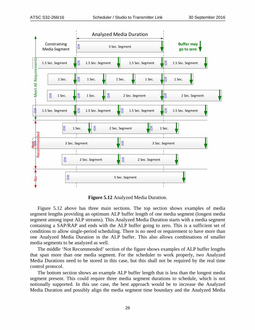
Figure 5.12 Analyzed Media Duration.
Figure 5.12 above has three main sections. The top section shows examples of media segment lengths providing an optimum ALP buffer length of one media segment (longest media segment among input ALP streams). This Analyzed Media Duration starts with a media segment containing a SAP/RAP and ends with the ALP buffer going to zero. This is a sufficient set of conditions to allow single-period scheduling. There is no need or requirement to have more than one Analyzed Media Duration in the ALP buffer. This also allows combinations of smaller media segments to be analyzed as well.
The middle ‘Not Recommended’ section of the figure shows examples of ALP buffer lengths that span more than one media segment. For the scheduler to work properly, two Analyzed Media Durations need to be stored in this case, but this shall not be required by the real time control protocol.
The bottom section shows an example ALP buffer length that is less than the longest media segment present. This could require three media segment durations to schedule, which is not notionally supported. In this use case, the best approach would be to increase the Analyzed Media Duration and possibly align the media segment time boundary and the Analyzed Media

ATSC S32-266r16 Scheduler / Studio to Transmitter Link 30 September 2016
27
Duration. In general terms, the possibility of staggered media segment start times may be handled by a longer Analyzed Media Duration and use of two corresponding buffers.
There is an absolute time at which negotiations among data sources and the Scheduler must be completed and the data delivered. This time is a Data Delivery Deadline and the Scheduler needs to analyze entire media segments to meet this Data Delivery Deadline. Current media segments must be sent before next media segments are loaded to meet each media segment Data Delivery Deadline. The ALP buffer should send all media segment contents at the end of every media segment, independent of whether there is an IDR frame at the beginning. Every media segment may be used to ensure ALP buffer flushing. The time deadline for delivery of the complete media segment can result in buffer going to zero. . There is no requirement that the buffer go to zero, as it is possible for the Scheduler to “pull forward” media from a future Analyzed Media Duration. Consider that the earliest delivery time can allow the Scheduler to deliver media in a physical layer frame to be delivered ahead of the one that could meet the latest requirement.
On each input ALP stream, media segment durations can vary (for layered coding), but they usually have an integer relationship in duration. For example, there can be ½ second media segments with 2 second enhancement media segments, or 1.5 second media segments with 3 second enhancement media segments, but preferably not ½ second media segments with ¾ second enhancement media segments. Note that ½ second and ¾ second segments could run in an Analyzed Media Duration of 1.5 seconds or 3 seconds. The constraining duration is the longest duration segment when all segment relationships are integer. The smallest Analyzed Media Duration that allows all segment durations present to be present in integer numbers. Smaller media segments can combine to form the length of the largest media segment as shown in Figure 5.12. 5.4.6 Sequence of Required Data and Media Events for Acquisition Figure 5.13 shows required data and associated events to achieve streaming media service with or without an application. There are two sequences of events. The first grouping is related to the physical layer. The Scheduler needs to understand that packets containing for example the SLT and SLS need to occur in tight time proximity after bootstrap and preamble. This shall be supported by identifying the relevant packet(s) as “Send in FEC Frame(s) Immediately Following the Preamble.” The cyclic temporal location of the bootstrap and preamble is likely aligned to media T-RAP timeline, so as to minimize wait states. Multiple staggered media start times and T-RAPs may require that multiple bootstraps and the associated signaling are required to minimize channel change time. If ROHC-U header compression is being utilized, then there is a need to synchronize the context refresh to functionally the T-RAP. This should be supported optionally as shown below in Figure 5.13.
The delivery of an application may be incremental, which is to say that each of the utilized or utilizable data objects for the application may not be delivered in the RAP. It is reasonable and good practice to define the RAP delivered portion of the app such that service acquisition and start may occur. Such details are out of scope for this document.
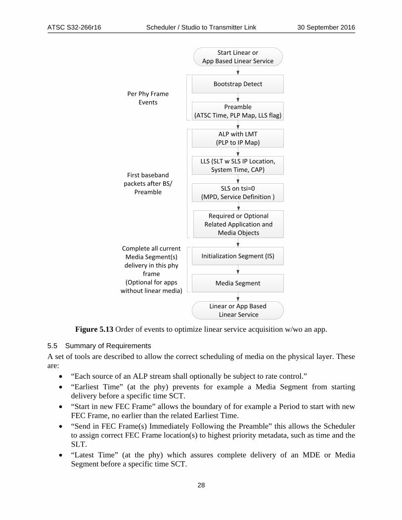
ATSC S32-266r16 Scheduler / Studio to Transmitter Link 30 September 2016
28
Bootstrap Detect
Preamble(ATSC Time, PLP Map, LLS flag)
SLS on tsi=0(MPD, Service Definition )
Initialization Segment (IS)
Media Segment
First baseband packets after BS/
Preamble
Per Phy FrameEvents
LLS (SLT w SLS IP Location, System Time, CAP)
ALP with LMT(PLP to IP Map)
Linear or App Based Linear Service
Start Linear or App Based Linear Service
Complete all currentMedia Segment(s)delivery in this phy
frame(Optional for apps
without linear media)
Required or OptionalRelated Application and
Media Objects
Figure 5.13 Order of events to optimize linear service acquisition w/wo an app.
5.5 Summary of Requirements A set of tools are described to allow the correct scheduling of media on the physical layer. These are:
• “Each source of an ALP stream shall optionally be subject to rate control.” • “Earliest Time” (at the phy) prevents for example a Media Segment from starting
delivery before a specific time SCT. • “Start in new FEC Frame” allows the boundary of for example a Period to start with new
FEC Frame, no earlier than the related Earliest Time. • “Send in FEC Frame(s) Immediately Following the Preamble” this allows the Scheduler
to assign correct FEC Frame location(s) to highest priority metadata, such as time and the SLT.
• “Latest Time” (at the phy) which assures complete delivery of an MDE or Media Segment before a specific time SCT.

ATSC S32-266r16 Scheduler / Studio to Transmitter Link 30 September 2016
29
• All to be delivered over the air ALP packets provided to the Scheduler shall be provided in delivery order.
These defined parameters are not transmitted to the receiver, as they are not needed for decode of media. The correct definition of these parameters and Scheduler adherence are required for continuous decode of media.
6. ALP TRANSPORT PROTOCOL The ALP delivery structure uses the ALP Transport Protocol (ALPTP), which applies between ALP sources and the STL input. There are potentially different data sources for each PLP, and ALP packets carry a single source data stream for each individual PLP. Any source multiplexing is upstream of ALP encapsulation and header compression functions.
All ALP packets shall be carried with RTP/UDP/IP multicast protocol using RTP headers modifications described in Section 6.3.
Identification of ALP packet streams is required to tie together packets of specific ALP streams and to provide identification of all packets in each ALP stream. Port numbers shall be used to differentiate ALP packets and to associate them with their respective ALP streams.
The system diagram in Figure 4.2 provides the functional context of the ALP transport protocol. It is possible that the actual implementation may be much more complicated requiring multiple sources of ALP packets. These sources could be for redundancy or could be external to the studio.
For example, consider a transmitter-sharing agreement where two physical layer pipes (PLPs) are dedicated to two separate stations. The individual studios could produce separate ALP packet streams that are then delivered for injection into the shared transmitter. If one of the studios was separated geographically, some sort of robust connection would be required to deliver the ALP packet stream to the scheduler / framing subsystem.
However, the ALP standard [5] is sufficient for an emission link layer standard and should not be burdened with additional functionality to ease intra- and inter-studio routing and distribution.
6.1 Overview ALP packets are distributed over UDP/IP multicast using a modified RTP protocol [6]. UDP/IP multicast is successfully used in many industries to deliver redundant video streams over copper and fiber physical layers. Routing and redundancy can be easily accomplished using IGMPv3 Source-Specific Multicast (SSM) (RFC 3569). Examples of various network configuration topologies are described in the Network Configuration Examples found in Annex B.
A multicast IP address is reserved along with a set of ports to map particular ALP packet streams to specific physical layer pipes (PLPs) (see section 6.4 below). By dedicating an address and ports to specific PLPs, distribution, routing, and recovery of data streams intended for transmission on specific PLPs is made easier.
Since UDP does not guarantee packet order or, in severe cases, delivery, RTP shall be used to maintain and allow reconstruction of the ALP packet order as well as to detect loss in the network. Because ALP packets can exceed the Maximum Transfer Unit (MTU) size of most IP installations, typically 1500 bytes, RTP framing features are used to allow systems to easily reconstruction of ALP packets upon reception. The RTP field details are defined in Section 6.3 below.

ATSC S32-266r16 Scheduler / Studio to Transmitter Link 30 September 2016
30
6.2 RTP/UDP/IP Multicast Considerations In addition to the context described above, it is recommended that RTP/UDP/IP Multicast with SSM be used throughout the studio when moving multicast traffic between producers and consumers. Here a ‘producer’ is defined as a device or process generating an IP multicast and a ‘consumer’ is a device or process receiving the IP multicast. Since RTP defines a ‘sequence number’ field, the various packets can be recovered and re-sequenced within each consumer. This allows packets to be reordered, duplicate packets to be ignored, and packet loss to be detected, possibly avoiding the problems sometimes encountered by UDP datagram delivery. RTP has framing information allowing relatively easy reconstruction of the enclosed ALP packet stream.
In redundant systems, the consumer must be aware of the several sources of contribution multicast streams. For each contribution stream, an IGMPv3 SSM ‘join’ is issued by the consumer for a particular multicast IP address, IP port number and source address. The combination of addresses and port numbers is referred to as a ‘tuple’. The router only sends UDP packets matching the specified tuple to the consumer's physical IP connection. If the consumer detects loss or problems with the particular packet stream, it can release that stream and join another using a different source address. The producers, in this case, operate independently and with no knowledge of the redundant topology.
6.3 ALPTP Design ALP describes the link-layer encoding for emitting various types of packets of a broadcast [5]. As indicated in the introduction to Section 6 above, the ALP protocol should not be burdened with routing requirements within the broadcast studio since these data are irrelevant to broadcast receivers. RTP is used to provide ordering, timing and framing information required to route ALP streams. RTP also allows extensions if other information is required, for example, for ECC or encryption. Placing delivery metadata in RTP allows the ALP data payloads to remain opaque to the transmission system.
The ALPTP design redefines one field of the standard RTP header and defines specific usage for three others. The marker (M) bit is defined by the RTP standard, RFC 3550 [6], to indicate significant events such as frame boundaries. The marker bit in ALPTP indicates that an ALP packet starts at the first byte following the RTP header fields. Note that the IP datagram payload may not contain a complete ALP packet, so the consumer should use the ALP packet lengths to reconstruct the ALP packet stream from incoming IP payloads. This is because the typical UDP/IP MTU size is 1500 bytes and ALP allows much larger packets. The marker (M) bit as well as the sequence number field of the RTP header can be used to resynchronize with the ALP headers and to determine the ordering of packets.
The timestamp and synchronization source identifier (SSRC) fields have been defined to carry specific scheduling information for the ALP packets contained within the RTP payload. The two fields define a time window, minimum and maximum times, respectively, when the contained ALP packet(s) is (are) to be emitted. The timestamp format is defined in Table 6.3.
Finally, the payload type field has been defined specifically for this application. Normally, there are payload types specified for particular types of content being streamed via RTP. This specification extends the dynamic payload types to explicitly define types of ALP content being carried. Some Low-Level Signaling (LLS) must be indicated in various data structures of the physical layer. The payload type identifies these specific ALPTP packets so that they may be handled appropriately. The payload type encoding is defined in Table 6.2.

ATSC S32-266r16 Scheduler / Studio to Transmitter Link 30 September 2016
31
Table 6.1 Provides the syntax of the RTP header for ALP delivery.
Table 6.1 RTP Header Field Definitions for ALP Encapsulation
Syntax No. of Bits Format
RTP_Fixed_Header() {
version (V) 2 '10'
padding (P) 1 bslbf
extension (X) 1 bslbf
CSRC_count (CC) 4 '0000'
marker (M) 1 bslbf
payload_type (PT) 7 uimsbf
sequence_number 16 uimsbf
timestamp_min() 32 Table 6.3
timestamp_max() 32 Table 6.3
}
Please refer to RFC 3550 [6] for base definitions of the fields described in Table 6.1. version – The version number of the RTP protocol. ‘2’ is currently defined by [6].
padding – Indicates that padding may be included in the payload. Padding will be supported as specified in [6].
extension – Indicates that an RTP extension follows the header. No extensions are required by this specification; however, the use of the standard extension shall be allowed. In other words, processors of the ALPTP must not preclude use of extensions.
CSRC_count – Indicates additional contributing source identifiers. No additional CSRCs are required, so this field shall be set to '0000'.
marker – A bit indicating a payload start. This bit is set to indicate that an ALP Packet starts at the first byte after the RTP header and any extensions. A consumer can synchronize with the packet stream by looking for the first packet containing a marker bit set to ‘1’. If the bit is not set, then the packet is a continuation of the previous packet payload as long as the sequence_number is monotonically increasing modulo 216 or 65536.
payload_type –The payload_type encoding defined here spans payload_type values from 80 (0x50) through 95 (0x5f), which are all in the undefined range documented in [7]. Table 6.2 defines additional payload types for ALP transmission.

ATSC S32-266r16 Scheduler / Studio to Transmitter Link 30 September 2016
32
Table 6.2 ALP RTP Packet payload_type Encoding Syntax No. of Bits Format payload_type() { prefix 4 '0101' alp_table_flag 1 bslbf if ( alp_table_flag == '0' ) { reserved 2 '00' table_type 1 bslbf } else { reserved 2 '00' lls_present_flag 1 bslbf } }
alp_table_flag – A 1-bit flag indicating that the remaining bits describe the particular ALP metadata structure, as opposed to the contents of an ALP data packet. Note that ALP metadata structures are carried in independent RTP packets.
table_type – A 1-bit flag that determines if the RTP packet contains an LMT ('0') or an RDT ('1'). The entire payload_value of 80 (0x50) corresponds to an LMT while 81 (0x51) indicates that an RDT is contained in the RTP packet.
lls_present_flag – A 1-bit flag indicating that the ALP packet payload contains at least one instance of a Low-Level Signaling table in compliance with [4]. A value of '1' indicates that the packet contains a Low-Level Signaling table. A value of '0' indicates that no LLS is present in the ALP payload. Note that the ALP packet stream shall have a marker bit set when any of the payload_types
are present; however, the LMT and RDT packets will likely be relatively small compared to other ALP data packets. These types are simply to notify the consumer that a Low-Level Signaling table is present within the particular payload. Note that most consumers will have no need to acquire the LMT or RDT and can simply pass them through with the other ALP packets. One application could be to modify the PLP_ID of these tables if a single ALP stream is directed at multiple PLPs, although this is not expected to be a typical use case. sequence_number – As per [6], the sequence_number shall increment by one for each packet
from the same source modulo 216 or 65536. The initial sequence_number should be randomized, although this is not important in this setting since the stream will be not be restarted frequently nor is it expected to be on a public network. Since UDP/IP does not guarantee ordered delivery and may even duplicate packets, the sequence_number can be used to reconstitute the stream as produced and to detect loss, allowing a backup stream to be selected.
timestamp_min – Defined by Table 6.3, this value shall specify the earliest time at which the start of the payload should be delivered. A value of ‘0’ shall indicate that the packet should be delivered with best effort. Timestamp times are only viable when the marker bit is set, indicating that the time is associated with the beginning of the ALP packet. The timestamp_min value shall be ignored when the marker bit is not ‘1’.
timestamp_max – Defined in Table 6.3, this value shall indicate the latest time at which the start of the payload should be delivered. A value of ‘0’ shall denote that the packet may be

ATSC S32-266r16 Scheduler / Studio to Transmitter Link 30 September 2016
33
delivered with best effort. Timestamp times are only viable when the marker bit is set, indicating that the time is associated with the beginning of the ALP packet. The timestamp_max field shall be ignored when the marker bit is not ‘1’. Note that this field replaces the SSRC_ID field specified in RFC 3550 [6].
Table 6.3 Timestamp Field Definitions for ALP Encapsulation
Syntax No. of Bits Format timestamp () { seconds 16 uimsbf fraction 16 uimsbf }
timestamp fields shall be formatted according to the short–form of NTP specified in RFC 5905 [15].
seconds shall carry a value equal to the 16 least significant bits (LSBs) of the seconds portion of the UTC time value of the targeted Bootstrap reference emission time.
fraction shall carry a 16-bit fractional seconds value of the UTC time of the targeted Bootstrap reference emission time—allowing a resolution of approximately 15 microseconds.
The timestamp fields within the RTP header allow an ALP encapsulation system to specify schedule constraints on delivery of the contained packets. Presumably, this scheduling information would be communicated somehow from upstream systems.
Please note that NTP is based on UTC and thus is adjusted for leap seconds. There is no adjustment for leap seconds in emission timing, which is based purely on TAI seconds and fractional seconds. See Section 7.2.2 for more information on Bootstrap emission timing.
6.4 Multicast Addressing The ALPTP stream shall be broadcast using a multicast address in the range 239.0.0.0 through 239.255.255.255, which is within the Organization Local Scope range defined by IETF. IP port numbers 30000 through 30063 shall be used corresponding to PLP 0 through 63, respectively.
7. STL TRANSPORT PROTOCOL
7.1 Preamble Data Generator Preamble information is constructed in the Preamble Generator according to instructions from the Scheduler. It is output by the Preamble Generator in the form of RTP/UDP/IP Multicast packets, similar to those used to carry Baseband Packets (BBPs) in PLP streams, so that they form a stream that can be multiplexed together with the PLP streams in the STLTP. The Preamble stream carries a description of the configuration of the transmitter processing functions and the resulting emitted waveform that is identical to the Preamble data structure sent to receivers.
To set up transmitter configurations, the Preamble must be sent from the Scheduler to the transmitter(s) at least 1 physical layer Frame in advance of the start of construction of the Frame by the transmitter(s).
To enable receivers to decode transmitted data, the same Preamble data used to configure the transmitter(s) will be included in the emitted signal immediately following the Bootstrap.

ATSC S32-266r16 Scheduler / Studio to Transmitter Link 30 September 2016
34
7.1.1 Preamble Data Stream Protocol The preamble data shall be delivered in an RTP/UDP/IP multicast stream conforming to RFC 3550 [6] with the constraints defined below. The maximum preamble data structure size can exceed the typical 1500-byte MTU, so a mechanism is defined herein to allow segmentation of the preamble data across multiple RTP/UDP/IP packets. Note that such segmentation only is required to conform with typical MTU sizes of 1500 bytes. If the local network allows larger multicast packets, this segmentation may not be required.
The payload data for each RTP/UDP/IP packet shall be a fragment of the Preamble Payload data structure described in Table 7.1. To provide validation that the L1_Basic_signaling and L1_Detail_signaling structures are delivered correctly over the STL, a 16-bit cyclic redundancy check is provided. The CRC is applied to the combined lengths of L1_Basic_signaling and L1_Detail_signaling and appended as the last 16 bitst of the payload data. The resultant stream of Preamble Payload packets shall be sent on UDP/IP multicast address 239.0.51.48 with port 30064.
Table 7.1 Preamble Payload Syntax No. of Bits Format Preamble_Payload () { length 16 uimsbf L1_Basic_signaling () 200 Table 9.2 of [3] L1_Detail_signaling () var Table 9.12 of [3] crc16 16 uimsbf }
The following paragraphs describe the fields shown in Table 7.1. The length field shall contain the number of bytes in the Preamble Payload data structure
following the length field. The length field allows receivers to avoid knowing the detailed syntax of preamble data structures and still to reconstruct the overall Preamble Payload data structure.
The crc16 field shall be the value resulting from application of a 16-bit cyclic redundancy check, as defined in [12], applied to the combined length, L1_Basic_signaling() and L1_Detail_signaling() structures in the Preamble Payload immediately preceding the crc16 field.
The Preamble Data Generator will form the necessary Preamble Payload data, as detailed in Table 7.1, from the Scheduler configuration and calculated information. Once the data structure has been populated, it will be partitioned into multiple RTP/UDP/IP packets, each conforming, with the necessary headers, to the local network MTU size. In summary, the resultant Preamble Payload packet set will typically consist of multiple packets of the same size followed by a smaller remainder packet. However, constructing the packets in this way is not normative.
The RTP header fields of the Preamble Payload packet set shall be set as described below with the marker (M) bit of a packet containing the beginning of a Preamble Payload data structure set to one (1). The marker (M) bit of the remaining packets shall be set to zero (0). This allows the transmission system on the receiver side of the STL to reconstruct the Preamble Payload data after any resequencing takes place. The timestamps of all of the packets of a given Preamble Payload packet set shall be set to the same valueas defined in Table 7.2. The timestamp values are derived from a subset of the Bootstrap_Timing_Data providing a mechanism to uniquely associate each of the Preamble Payload packets with a specific frame.

ATSC S32-266r16 Scheduler / Studio to Transmitter Link 30 September 2016
35
Table 7.2 RTP Header Timestamp Field Definitions
Syntax No. of Bits Format timestamp () { seconds 22 uimsbf milliseconds 10 uimsbf }
seconds shall carry a value equal to the 22 least significant bits (LSBs) of the seconds portion of the Bootstrap_Timing_Data described in Table 7.3.
milliseconds shall carry a 10-bit value identical to the value contained in the the 3rd through the 12th MSBs of the nanoseconds value described in Table 7.3
On receipt, the Preamble Payload packet shall be resequenced and extracted into the Preamble Payload data structure as described in Table 7.1. The receiver can accumulate RTP packets until it has received all of the bytes defined by the length field in the first packet. If a packet is missed, as determined by a missing sequence number, or if a packet with the marker (M) bit set is received prematurely, indicating the start of the next Preamble Payload packet set, then one or more packets have been lost and the entire Preamble Payload data set has been lost. Any accumulated data shall be discarded.
The RTP header fields shall follow the syntax defined in RFC 3550 [6], with the following additional constraints: The Padding (P) bit shall conform to the RFC 3550 [6] specification. The Extension (X) bit shall be set to zero (0), indicating the header contains no extension. The CSRC Count (CC) shall be set to zero (0), as no CSRC fields are necessary. The marker (M) bit shall be set to one (1) to indicate that the first byte of the payload is the start
of the Preamble Payload data. A zero (0) value shall indicate that the payload is a continuation of the Preamble Payload data from the previous packet.
The Payload Type (PT) shall be set to 77 (0x4d), indicting the Preamble Payload payload type. The Sequence Number shall conform to the RFC 3550 [6] specification. The Timestamp shall be defined as in Table 7.2. The timestamp shall be set to the same value
for all of the Preamble Payload Packet Set. The Synchronization Source (SSRC) Identifier shall be set to zero (0). There should be no
other sources of Preamble Payload data carried by the STLTP. Any redundant sources can be managed using IGMP Source Specific Multicast (SSM) mechanisms, thereby filtering packets at the router.
7.2 Timing Data Generator Timing and Management information is constructed in the Timing and Management Generator according to instructions from the Scheduler. It is output by the Timing and Management Generator in the form of RTP/UDP/IP Multicast packets, similar to those used to carry Baseband Packets (BBPs) in PLP streams, so that they form a stream that can be multiplexed together with the PLP streams in the STLTP. These Timing and Management packets are not emitted. The resulting Timing and Management stream carries a set of instructions for controlling the emission of physical layer Frames comprising a Bootstrap, and Preamble, and payload packets. The configurations of the Bootstrap and certain other components of the Frame are carried in the Timing and Management stream. Also included in the Timing and Management stream are the emission time of each Bootstrap and, hence, the start of each Frame, the offset times of each

ATSC S32-266r16 Scheduler / Studio to Transmitter Link 30 September 2016
36
transmitter in an SFN from the reference Bootstrap emission time for the network, and other information used to control the transmitter(s).
To set up transmitter configurations, the Timing and Management data for a Frame must be sent from the Scheduler to the transmitter(s) at least 1 physical layer Frame in advance of the start of construction of the Frame by the transmitter(s). 7.2.1 Timing and Management Data Stream Protocol The Timing and Management data shall be delivered in an RTP/UDP/IP multicast stream conforming to RFC 3550 [6] with the constraints defined below. Each data packet shall not exceed 1500 bytes including the RTP/UDP/IP headers. Note that this limits the packet payload to a maximum of 1460 bytes. The payload shall conform with syntax described in Table 7.3. The packet size limit should pose no problem since the timing and management data payload can be partitioned into multiple groups. The data stream shall be sent on UDP/IP multicast address 239.0.51.48 with port 30065.
The RTP header fields shall follow the syntax defined in RFC 3550 [6] with the following additional constraints: The Padding (P) bit shall be set to zero (0) indicating no padding is present in the Timing and
Management Data packet. The Extension (X) bit shall be set to zero (0) indicating the header contains no extension. The CSRC Count (CC) shall be set to zero (0) as no CSRC fields are necessary. The marker (M) bit shall be set to zero (0) since all Timing and Management Data packets are
formed with the same syntax. The Payload Type (PT) shall be set to 78 (0x4c) indicting the Timing and Management Data
payload type. The Sequence Number shall conform to the RFC 3550 [6] specification. The Timestamp shall be defined as in Table 7.2. The Synchronization Source (SSRC) Identifier shall be set to zero (0). There should be no
other sources of Timing and Management data carried by the STLTP. Any redundant sources can be managed using IGMP Source Specific Multicast (SSM) mechanisms thus filtering packets at the router.

ATSC S32-266r16 Scheduler / Studio to Transmitter Link 30 September 2016
37
Table 7.3 Timing and Management Stream Packet Payload Syntax No. of Bits Format Timing & Management_Packet (TMP) () { Structure_Data () { length 16 uimsbf version_major 4 uimsbf version_minor 4 uimsbf maj_log_rep_cnt_pre 4 uimsbf maj_log_rep_cnt_tim 4 uimsbf bootstrap_major 4 uimsbf bootstrap_minor 4 uimsbf min_time_to_next 5 uimsbf system_bandwidth 2 uimsbf bsr_coefficient 7 uimsbf preamble_structure 8 uimsbf eas_wakeup 2 bslbf num_emission_tim 6 uimsbf num_xmtrs_in_group 6 uimsbf xmtr_group_num 7 uimsbf maj_log_override 3 bslbf reserved 10 for (i=0; i<10; i++) ‘1’ } Bootstrap_Timing_Data () { for (i=0; i<=num_emission_tim; i++) seconds 32 uimsbf nanoseconds 32 uimsbf } } Per_Transmitter_Data () { for (i=0; i<num_xmtrs_in_group; i++) { xmtr_id 13 uimsbf tx_time_offset 16 tcimsbf txid_injection_lvl 4 uimsbf reserved 31 for (i=0; i<31; i++) ‘1’ } } Error_Check_Data () { reserved 16 crc16 16 uimsbf } }
length shall indicate the number of bytes in the Timing and Management data packet following the RTP/UDP/IP header structure. Up to 65,535 Bytes can be indicated, although it is expected that the size of Timing and Management packets will be limited to 1500 Bytes, including headers, i.e., limited to 1472 Bytes of payload.
ATSC S32-266r16 Scheduler / Studio to Transmitter Link 30 September 2016
38
version_major, in conjunction with version_minor, shall indicate the version of the protocol used to construct the Timing and Management data packet. Increments in the value of version_major are intended to indicate changes in the structure that are not fully compatible with lower-ordered version_major values. The value of version_major can range from 0 through 15. Timing and Management packets constructed according to this version of this standard shall have the value of version_major set to 0.
version_minor, in conjunction with version_major, shall indicate the version of the protocol used to construct the Timing and Management data packet. Increments in the value of version_minor are intended to indicate changes in the structure that are fully backward compatible with lower-ordered version_minor values.
maj_log_rep_cnt_pre shall indicate the number of repetitions of Preamble data in the Preamble Stream at UDP port 30064 prior to emission of the Preamble. Permitted values are 1, 3, 5, 7, and 9. Note that values for L1B_lls_flag and L1D_plp_lls_flag may be correct only in the final copy of the Preamble data sent to transmitters prior to emission. Consequently, majority logic error correction can be applied reliably to all portions of the Preamble Stream data except the two flag values noted. See Section XX for details of placement of the repeated data.
maj_log_rep_cnt_tim shall indicate the number of repetitions of Timing & Management data in the Timing & Management Stream at UDP port 30065 prior to emission of the next Bootstrap. Permitted values are 1, 3, 5, 7, and 9. Note that values for the eas_wakeup bits may be correct only in the final copy of the Timing & Management data sent to transmitters prior to emission. Consequently, majority logic error correction can be applied reliably to all portions of the Timing & Management Stream data except the eas_wakeup values noted. See Section YY for details of placement of the repeated data.
bootstrap_major shall indicate the value of the bootstrap_major_version of the bootstrap symbols that introduce the Frame identified by the Bootstrap Timing Data (), which value shall correspond to the root of the Zadoff-Chu sequence of the bootstrap symbols, as specified in [2].
bootstrap_minor shall indicate the value of the bootstrap_minor_version of the bootstrap symbols that introduce the Frame identified by the Bootstrap Timing Data (), which value shall provide the seed for the PN sequence of the bootstrap symbols, as defined in [2].
min_time_to_next shall be the enumerated value indicating the minimum time until the next frame of the same type as defined in [2].
system_bandwidth shall be the enumerated value indicating the bandwidth of the RF transmission channel as defined in [2].
bsr_coefficient shall be the binary value associated with the baseband sampling frequency as defined in [2].
preamble_structure shall be the enumerated value indicating the preamble configuration as defined in [3].
num_emission_tim shall indicate the number of sequential Bootstrap emission reference times that are contained within the Bootstrap_Timing_Data() ‘for’ loop. Up to 64 values may be indicated. The values shall range from 0 thru 63, and shall be expressed as the number of values carried in the packet minus 1. At least the next Bootstrap reference emission time shall be carried and shall be carried in index 0 of the ‘for’ loop.
eas wakeup shall signal the states of the two eas wakeup bits to be included in the Bootstrap signal at the start of the next Frame to be emitted.

ATSC S32-266r16 Scheduler / Studio to Transmitter Link 30 September 2016
39
num_xmtrs_in_group shall indicate the number of transmitters to which data is addressed in the Per_Transmitter_Data () ‘for’ loop. The value can be less than the total number of transmitters in the network, in which case data addressed to groups of transmitters shall be sequenced in order across multiple Timing & Management Data packets.
xmtr_group_num shall indicate the ordinal number of a group of transmitters to which information in the Per_Transmitter_Data() loop is addressed. The value of the field may range from 0 through 128. Only a single value of xmtr_group_num shall apply to a given Timing & Management Stream data packet. Information for individual transmitters shall be organized in groups identified by values of xmtr_group_num starting at 0 and incrementing by 1 from one Timing & Management Stream data packet to the next, until the highest-numbered group is reached, at which point the value shall start again at 0 in the following such packet.
Bootstrap_Timing_Data() shall contain a list of the Bootstrap reference emission times of the next and, optionally, successive future frames, the list having a total number of entries equaling the value of num_emission_tim. The values of the Bootstrap reference emission times shall increase monotonically from the first entry in the list to the last.
maj_log_override shall indicate that all previous instances of Timing and Management data and Preamble data for the next and following physical layer frames shall be ignored and that the information in the current Timing and Management packet and a subsequent Preamble data packet shall be used to configure the next physical layer frame. The non-override condition shall be indicated by a value of ‘000’ in this field. An override condition shall be indicated by a value of ‘111’ in this field.
seconds shall carry a value equal to the 32 least significant bits (LSBs) of the seconds portion of the UTC time value of the associated Bootstrap reference emission time, as expressed using the Precision Time Protocol (PTP) defined in [13] and [14].
nanoseconds shall carry a value equal to the nanoseconds portion of the UTC time value of the associated Bootstrap reference emission time. It shall be expressed as a 32-bit binary value having a range from 0 through 999,999,999 decimal.
Per_Transmitter_Data() shall contain information addressed individually to one or a group of transmitters, with the number of transmitters for which data is included in the loop equaling the value in num_xmtrs_in_group.
txid_address shall indicate the address of the transmitter to which the following values are being sent and shall correspond to the seed value used by the TxID code sequence generator of that transmitter. The value of the address shall be an unsigned integer binary number having a range of possible values from 0 through 8191 decimal.
tx_time_offset shall indicate the emission time offset of the transmitter to which it is addressed relative to the Bootstrap reference emission times of all frames. The transmitter time offset shall be expressed in units of positive or negative integer steps of 100 ns and shall be a two’s complement signed integer binary number having a range from –32,768 through +32,767 decimal, representing time offsets from –3,276.8 through +3,276.7 microseconds.
txid_injection_lvl shall indicate the Injection Level of the TxID signal below the average power of the Preamble symbols emitted by the transmitter to which its value is addressed. The Injection Level shall correspond to the value in dB listed in A/322 Table N.3.1 for the TxID Injection Level Code included in the txid_injection_lvl field (or Off for code value 0000).

ATSC S32-266r16 Scheduler / Studio to Transmitter Link 30 September 2016
40
crc16 shall be the value resulting from application of a 16-bit cyclic redundancy check, as defined in [12], applied to all fields in the Timing and Management Packet payload from the length field through the field (and any reserved bits) immediately preceding the crc16 field. 7.2.2 Bootstrap Emission Timing and Frame Identification Reference Bootstrap emission time shall be used for frame identification. In the RTP headers of the STLTP, the timestamp fields are used to carry number patterns matching portions of a complete Reference Bootstrap emission time. The portions matched have been selected for unique identification of the Frames with which the STLTP packets are associated. The portions of the Reference Bootstrap Emission time used for identification are the 22 LSBs of the seconds value and the 3rd through 12th MSBs of the nanoseconds value, the latter of which represent approximately millisecond time increments. The selected portions of the Reference Bootstrap emission time are sufficient to assure no ambiguity in the association of STLTP packets with Frames. 7.2.2.1 Baseband Packet Delivery The Framer functionality accepts ALP packets from the transport layer as described in [5]. All ALP packets are converted to baseband packets as described in [3]. This complete description of the baseband data to be radiated and has known destination(s) in the physical layer according to the associated preamble. The baseband framer then encapsulates baseband packets into RTP/UDP/IP packets per scheduler instructions and destination PLPs. 7.2.3 PLP Data Stream Each PLP is parallel data, simultaneous in time and inherently packetized into baseband frames. The payload must be steered for correct PLP processing. The port number used to deliver each ALP stream, as described in Section 6, associates the ALP stream with a particular PLP. 7.2.4 Baseband Frame Data Stream Protocol The baseband frame data shall be delivered in an RTP/UDP/IP multicast stream conforming to RFC 3550 [6] with the constraints defined below. The maximum baseband frame data structure can exceed the typical 1500 byte MTU so a mechanism is defined herein to allow segmentation of the baseband frame data across multiple RTP/UDP/IP packets. Note that this is only required to conform with typical MTU sizes of 1500 bytes. If the local network allows larger multicast packets, this segmentation may not be required.
The payload data for each RTP/UDP/IP packet shall be a fragment of the baseband frame data structure as defined in [3]. The collection of segmented packets representing a single baseband frame is referred to hereafter as the Baseband Frame Packet Set. The resultant packet stream shall be sent on UDP/IP multicast address 239.0.51.48 with IP port 30000 through 30063, corresponding to each of the PLPs.
The Framer will form each baseband frame from each incoming ALP data stream as described above. Once the baseband frame is ready for emission, it will be partitioned into multiple RTP/UDP/IP packets each conforming, with the necessary headers, to the local network MTU size. In summary, the resultant Baseband Frame Packet Set will typically consist of multiple packets of the same size followed by a smaller remainder packet. However, constructing the packets in this way is not normative and any size or number of packets is allowed.
The RTP header fields of the packet set will be set as described below with the marker (M) bit of the first packet containing the beginning of the baseband frame set to one (1). The marker (M) bit of the remaining packets will be set to zero (0). This allows the transmission system on

ATSC S32-266r16 Scheduler / Studio to Transmitter Link 30 September 2016
41
the receiver side of the STL to reconstruct the baseband frame after any resequencing takes place. The timestamp of all of the packets for a given Baseband Frame Packet Set shall be set to the same value indicating the emission time of the frame. In addition to the marker (M) bit being set on the first packet, the Synchronization Source (SSRC) Identifier field shall be set to the overall length of the Baseband Frame data structure in bytes across the entire Baseband Frame Packet Set for a given PLP.
On receipt, the Baseband Frame Packet Set shall be resequenced and extracted into the baseband frame data structure. If a packet is missed as determined by a missing sequence number or if a packet with the marker (M) bit set is received indicating the start of the next Baseband Frame Packet Set, then one or more packets have been lost and the entire baseband frame has been lost. Any accumulated data shall be discarded.
The RTP header fields shall follow the syntax defined in RFC 3550 [6] with the following additional constraints: The Padding (P) bit shall conform to the RFC 3550 [6] specification. The Extension (X) bit shall be set to zero (0) indicating the header contains no extension. The CSRC Count (CC) shall be set to zero (0) as no CSRC fields are necessary. The marker (M) bit shall be set to one (1) to indicate that the first byte of the payload is the start
of the baseband frame. A zero (0) value indicates that the payload is a continuation of the baseband frame from the previous packet.
The Payload Type (PT) shall be set to 77 (0x4e) indicting the baseband frame payload type. The Sequence Number shall conform to the RFC 3550 [6] specification. The Timestamp shall be defined as in Table 7.2. The timestamp shall be set to the same value
for all packets of a given Baseband Frame Packet Set. If the marker (M) bit is zero (0), the Synchronization Source (SSRC) Identifier shall be set to
zero (0). If the marker (M) bit is set to one (1), indicating the first packet of the Baseband Frame Packet Set, the SSRC field will contain the total length of the Baseband Frame data structure in bytes. This allows the receiver to know how much data is to be delivered within the payloads of the Baseband Frame Packet Set.
7.3 Studio to Transmitter Link (STL) Protocol Overview The STL transport protocol (STLTP) shall be an RTP/UDP/IP multicast stream based on the SMPTE ST 2022-1 [8] standard. SMPTE ST 2022-1, in turn, extends the RTP [6] protocol with Generic FEC Payload Format [8]. RTCP and other control streams are explicitly excluded by SMPTE ST 2022-1 ([8] § 7.1, ¶ 2).
To use SMPTE ST 2022-1, all STL communications shall be coalesced into a single IP stream with a fixed packet size. This is known as ‘tunneling’. Both single and two dimensional FEC schemes are supported. Note that, per ST 2022-1, column and row FEC packets shall be sent on separate ports to the same multicast address as the primary data stream. No IP header compression will be performed. The RTP marker (M) bit combined with an offset field will allow receivers to determine where IP headers begin within a given tunnel payload. The packet streams destined for the STL shall be collected into fixed-size RTP payloads, XOR FEC calculations shall be performed, if enabled, and the resulting packets shall be sent according to [8].
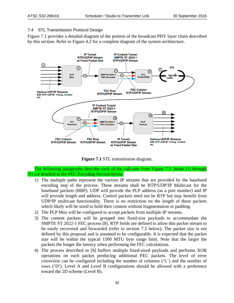
ATSC S32-266r16 Scheduler / Studio to Transmitter Link 30 September 2016
42
7.4 STL Transmission Protocol Design Figure 7.1 provides a detailed diagram of the portion of the broadcast PHY layer chain described by this section. Refer to Figure 4.2 for a complete diagram of the system architecture.
Figure 7.1 STL transmission diagram.
The following paragraphs describe each of the call-outs from Figure 7.1. Items (1) through (5) are detailed in the FEC Encoding Section below.
1) The multiple paths represent the various IP streams that are provided by the baseband encoding step of the process. These streams shall be RTP/UDP/IP Multicast for the baseband packets (BBP). UDP will provide the PLP address (as a port number) and IP will provide length and address. Control packets need not be RTP but may benefit from UDP/IP multicast functionality. There is no restriction on the length of these packets which likely will be sized to hold their content without fragmentation or padding.
2) The PLP Mux will be configured to accept packets from multiple IP streams. 3) The content packets will be grouped into fixed-size payloads to accommodate the
SMPTE ST 2022-1 FEC process [8]. RTP fields are defined to allow this packet stream to be easily recovered and forwarded (refer to section 7.5 below). The packet size is not defined by this proposal and is assumed to be configurable. It is expected that the packet size will be within the typical 1500 MTU byte range limit. Note that the larger the packets the longer the latency when performing the FEC calculations.
4) The process described in [8] buffers multiple fixed-sized payloads and performs XOR operations on each packet producing additional FEC packets. The level of error correction can be configured including the number of columns (‘L’) and the number of rows (‘D’). Level A and Level B configurations should be allowed with a preference toward the 2D scheme (Level B).

ATSC S32-266r16 Scheduler / Studio to Transmitter Link 30 September 2016
43
5) The primary content stream along with up to two FEC packet streams are sent using three RTP/UDP/IP multicasts on three separate ports. If the primary content stream is sent on IP address 239.xxx.xxx.xxx with port N, then the first FEC stream is sent on address 239.xxx.xxx.xxx with port N+2 and the second FEC stream is sent on port N+4. This is in accordance with SMPTE ST 2022-1 ([8] §8.1, ¶6).
6) The three streams will be received by an IP-capable STL transmitter where it will be …
7) Sent via the STL to …
8) The STL receiver where it will be extracted into … 9) Three RTP/UDP/IP streams; i.e. the primary content tunnel and up to two FEC streams. 10) These streams will be received and processed by the SMPTE ST 2022-1 decoder. Note
that the decoder will determine missing packets from the RTP sequence numbers on the primary content tunnel stream and reconstitute them.
11) The resultant packet stream will be an in-order collection of fixed-size packets identical to the input stream described in step (3) above.
12) The PLP Demux will extract each packet from the payloads within the tunnel packets. The tunnel packets RTP headers contain information allowing the packets to be reframed.
13) The reconstituted IP packets are then forwarded on to the remaining stages of the transmission system.
7.4.1 Example SMPTE 2022-1 FEC Encoding Process Figure 7.2 provides a detailed example diagram of how the various content packets are encoded into ST 2022-1 [8] FEC packets. This exemplifies some of the steps highlighted in Figure 7.1. The process shown in Figure 7.2 implements steps 2, 3, and 4 from Figure 7.1. While Figure 7.1 shows the IP Tunnel (3) as a separate line, these packets will typically exist only in memory just prior to the FEC step. A similar decode process will also occur where these packets will be gathered into memory, FEC will be used to replace missing packets and the tunneled packets will be extracted directly from the in-memory buffers.

ATSC S32-266r16 Scheduler / Studio to Transmitter Link 30 September 2016
44
Figure 7.2 Example FEC encoding process diagram.
The following paragraphs describe each of the call-outs from Figure 7.2. 1) The multiple paths represent the various IP streams that are provided by the baseband
encoding step of the process. These streams shall be RTP/UDP/IP Multicast for the baseband packets (BBP) since RTP will provide the sequence and emission timing of the packets, UDP will provide the PLP address (as a port number) and IP will provide length and address. Control packets need not be RTP but may benefit from UDP/IP multicast functionality. There is no restriction on the length of these packets which likely will be sized to hold their content without fragmentation or padding.
2) As packets are received from the input interface, they are placed in memory as they are received. The conceptual memory buffer will be preconfigured to contain as many packets as required to meet the FEC configuration of packet columns (‘L’) and rows (‘D’) with the packet payloads and placeholder RTP headers. The appropriate marker bit and offset fields will be updated in these headers as the input packets are saved into the buffers.
3) The example packet contents diagrams a conceptual model of how input packets are placed into individual tunnel packet buffers. Packets will be placed into the buffer sequentially as received. If an input packet exceeds the length of the current tunnel packet buffer, the portion of the input packet that fits will be placed into the buffer and the remainder placed into the next buffer. The offset field of the next tunnel packet buffer RTP header will be set to indicate the byte of the next packet start within the tunnel packet payload and the marker bit will be set to indicate that a payload (i.e. input packet)

ATSC S32-266r16 Scheduler / Studio to Transmitter Link 30 September 2016
45
start is present within the particular buffer. Note that it is quite possible for a BBP to span multiple tunnel packets. An example of this packing process is described in detail in section 7.5.1 below.
4) When a column or row is completed, the FEC function (XOR per [8]) is performed creating an FEC packet for the column or row, respectively. The headers and content of these packets are described in [8] and [8].
5) The FEC packets along with the content tunnel packets are sent per the guidelines defined in [8]. There are a number of packet interleaving options which could be configured based on the number of columns and rows defined and the system latency desired.
7.5 RTP Header Field Definitions The STLTP RTP/UDP/IP multicast packets shall contain an RTP header compliant with the header fields specified in [8], Section 7.1, with the changes described below. In addition to the constraints defined by [8], this document changes the definition of one of the standard fields to enable internal payload framing. The marker (M) bit along with the repurposed SSRC_ID field, now defined as the packet_offset, shall be used to identify the start of the first IP packet within the payload of the particular RTP packet. This mechanism is described in more detail below.
Table 7.4 defines the fields of the STLTP RTP header. Paragraphs following the figure describe each of the fields.
Table 7.4: RTP Header Field Definitions for STLTP
Syntax No. of Bits Format
RTP_Fixed_Header() {
version (V) 2 '10'
padding (P) 1 '0'
extension (X) 1 '0'
CSRC_count (CC) 4 '0000'
marker (M) 1 bslbf
payload_type (PT) 7 '1100001'
sequence_number 16 uimsbf
timestamp 32 Table 7.2
packet_offset 32 uimsbf
}
Please refer to [6] for base definitions of the fields described in Table 7.4 and refer to [8] §7.1 for constraints to those base definitions. version – The version number of the RTP protocol. ‘2’ is currently defined by [6].
padding – Indicates that padding may be included in the payload. No padding is required by this proposal however it may be necessary to add padding if the aggregate incoming bit rate falls below a certain threshold. It is currently assumed that the overall broadcast stream will be essentially constant since it must synchronize with a constant broadcast bit rate. Under RTP

ATSC S32-266r16 Scheduler / Studio to Transmitter Link 30 September 2016
46
[6] rules, the last byte of the payload is used to indicate the number of padding bytes in the payload.
extension – Indicates that an RTP extension follows the header. No extensions are currently defined.
CSRC_count – Provides the count of additional contributing source identifier fields. ST 2022-1 [8] requires this field to be set to ‘0’.
marker – A bit indicating a payload start. When the marker bit is set to ‘1’, the first byte of the first IP packet starting within the payload will be indicated by the value of the packet_offset field. Subsequent IP packets can be found by using the length fields within each packet. Typically, the bytes proceeding the IP packet start will be the continuation of the last packet from the previous payload.
payload_type – As payload types are defined in [7], values from 97 through 127 decimal are allocated for dynamic assignment. It is recommended to set this field to ’97,’ but values between ‘97’ and ‘127’ may be used.
sequence_number – As per [6], the sequence_number shall increment by one for each packet of an RTP stream modulo 216 or 65536. The initial sequence_number should be randomized though this is not important in this setting since the stream will be not be restarted frequently nor are these packets expected to be placed on a public network. Since UDP/IP does not guarantee ordered delivery and may even duplicate packets, the sequence_number can be used to reorder the stream as produced and detect missing packets. In this specification, ‘stream’ refers to a set of packets destined for the same IP address and port. SMPTE ST 2022-1 [8] relies on the sequence_number to determine where content packets are placed in sequence to allow replacement of missing packets. Note that the sequence_number applies to each individual stream. The FEC packets will have different sequence numbers from the content tunnel packets.
timestamp – The timestamp value shall indicate the Reference Bootstrap emission time of the earliest Frame in which any of the content of the associated packet is intended to be emitted.
packet_offset – This field redefines the RTP SSRC_ID field [6]. Under [8], this field can be assigned to any value and is to be ignored by the receiver. Under this proposal, if the marker bit is set, this field defines the payload offset of the first IP content packet. The field holds the number of bytes after the RTP header where the first IP packet starts within the payload. If the IP packet starts immediately after the header, then packet_offset will be 0. Figure 7.3 provides a graphical example of how input IP packets are encapsulated within the fixed-size SMPTE ST 2022-1 RTP packets.

ATSC S32-266r16 Scheduler / Studio to Transmitter Link 30 September 2016
47
7.5.1 RTP Encapsulation Example
Figure 7.3 RTP Encapsulation example diagram.
The following paragraphs describe each of the call-outs in Figure 7.3. Note that this is an example of a potential implementation to illustrate how the fixed-size packets are constructed according to this specification. Actual implementations could differ substantially however the resulting packet stream would have the same semantic organization.
1) A standard RTP/UDP/IP header proceeds each of the fixed-size packets which contain the content to be protected by the ST 2022-1 FEC process. This header can be initialized for all of the packets in the process and only specific fields need to be modified during the encapsulation process. Fields such as length, IP address, port numbers, etc. need not be changed once the buffers have been initialized.
2) The example in Figure 7.3 is from the decoding standpoint showing how the packets would be perceived on the receive side, assuming that the receiver started at an arbitrary packet of an ongoing stream of packets. Each packet in the stream contains a header and payload which may or may not contain the start of an IP content packet.
3) If the marker bit is on, signified in the diagram by an asterisk in the RTP header box, then the packet_offset (4) will be used to indicate the byte where the first IP packet starts within the payload.
4) The packet_offset is the number of bytes after the RTP header where the first byte of first IP header resides within the payload. This field is only used if the marker bit is set to ‘1’. Note that when more than one packet starts in the payload, only the first is indicated by the packet_offset. This is shown in Figure 7.3 at packets (B) and (C). The start of packet (B) is indicated by the packet_offset just after the remainder of packet (A). The start of packet (C) can be determined using the length of packet (B). Of course, the start of packet (B) could also be determined by using the total length of packet (A) which started in the previous 2022-1 fixed-size packet. Robust decoders would likely use both the length of the previous packet as well as the packet_offset to verify the encapsulation process and that the payload packets were correctly formed. This mechanism of framing the encapsulated IP streams allows receivers to recover lost connections quickly since only one or two fixed size packets are required to begin extracting the tunneled packets.
5) The tunneled content packet labeled (C) in the figure shows a large packet spanning three ST 2022-1 fixed-size packets. In this case, the middle 2022-1 packet does not have the marker bit set and the packet_offset field would be ignored by the receiver.

ATSC S32-266r16 Scheduler / Studio to Transmitter Link 30 September 2016
48
7.6 SMPTE ST 2022-1 Features / Resources The STLTP shall be a derivative of SMPTE ST 2022-1 [8]. SMPTE ST 2022-1 [8] is defined to allow encapsulated MPEG-2 transport streams to be delivered over RTP/UDP/IP in a robust manner applying various levels of FEC as desired. The sections above describe a mechanism of encapsulating various forms of IP packets instead of MPEG-2 transport stream packets within an ST 2022-1 stream to take advantage of the robustness provided by that protocol.
In addition to the constraints defined by [8], Section 7.5 above redefines the SSRC_ID field. This field, along with the marker (M)marker (M) bit, provides a means of framing IP packets within the STLTP payloads for easy reconstruction on the receiver side. All other aspects of ST 2022-1 remain identical to the capabilities described in [8] including support for any FEC constraints detailed in §8 of that standard.
8. TRANSMITTER OPERATION NORMATIVE REQUIREMENTS
8.1 Timing Manager The Timing Manager shall receive, buffer, and process the Timing and Management data in the form described in Section 7.2 from the STL PLP Demux, as shown in Figure 4.2 (heavy, light-orange line). Timing and Management data will arrive at a transmitter in advance of the time for its application. It shall control the overall operation of the transmitter and the times at which the numerous processes in the transmitter are executed. The data that it receives is not intended for emission but rather for control purposes only.
The Timing Manager also shall receive time information directly from a highly accurate source such as the Global Navigation Satellite System (GNSS) or communicated through a data stream capable of precise time information transfer such as the Precision Time Protocol (PTP). The time information shall be used to accurately control the emission time of the leading edge of the first Bootstrap symbol of each physical layer frame. The same timing information used for control of emission timing also shall be capable of use for derivation of a precise frequency reference for control of the transmitter emission frequency.
The Timing and Management data shall be stored in a buffer to permit transmission of Bootstrap emission times by the Scheduler to the transmitters well in advance of those emission times. The size of the buffer should be determined from the maximum advance of delivery time of the Bootstrap emission time information permitted by the specification of the Timing and Management data stream protocol.
The primary data carried by the Timing and Management data stream is the Bootstrap Emission Time at which each physical layer frame is to be emitted. Multiple instances of the Timing and Management data for a given frame may be sent to transmitter(s) by the Scheduler. Those instances will be identified as to the physical layer frame that they are describing by having a matching time value indicating the Bootstrap emission time of the frame. The multiple instances can be held in a buffer and used by the Timing Manager to improve reliability of the Timing and Management data through application of majority logic or other processing of the redundant copies of the data.
The number of copies of the Timing and Management data that are being sent by the Scheduler to the transmitter(s) is indicated in the Timing and Management data stream, as specified in Table 7.3. Similarly, the number of copies of the Preamble data that are being sent by the Scheduler to the transmitter(s) also is indicated in the Timing and Management data

ATSC S32-266r16 Scheduler / Studio to Transmitter Link 30 September 2016
49
stream. The number of Preamble copies being sent by the Scheduler shall be communicated by the Timing Manager to the Preamble Parser so that it can utilize similar processing of the redundant data for purposes of improving reliability of the data.
Other functions of the Timing Manager are: • Control of the configuration of Bootstrap symbols, waveforms, and the data carried • Control of the emission times of Bootstrap symbols • Compensation of the transmitter-to-antenna (TAD) emission delay • Control of buffer delays in the transmitter data processing path
o Including compensation for STL network delivery delays in SFNs • Control of Preamble data insertion following Bootstrap emission • Parsing of Timing and Management data for individual transmitters in SFNs • Control of transmitter emission time offset in SFN operation • Control of TxID insertion
o Including insertion level and off
8.2 Preamble Parser The Preamble Parser shall receive and buffer Preamble data in the form described in Section 7.1 from the STL PLP Demux, as shown in Figure 4.2 (heavy, light-blue line). Preamble data will arrive at a transmitter in advance of the time for its emission. It shall be used in two ways: (1) to set up the transmitter data and signal processing as controlled by the Scheduler through the emitted Preamble data and (2) to deliver to the Preamble Inserter block the Preamble data stream at the correct time for its emission in the transmitted signal.
To achieve the two required uses of the Preamble data, the Preamble Parser shall provide two primary functions. The first function shall be a buffer that holds the Preamble data stream until it is needed for emission. The output of the buffer shall release the Preamble data stream to the Preamble Inserter (thin, light-violet line in Figure 4.2) at the appropriate time, as determined by the Timing Manager, so that emission of the Preamble data occurs immediately following emission of the Bootstrap. Both the length data at the start and the crc16 value at the end of the Preamble Payload data packet shall not be emitted by the transmitter and can be deleted after any use by the transmitter for error detection. The second function shall be parsing of the data in the Preamble into separate instructions for each of the data- and signal-processing stages of the transmitter and delivery of those instructions to the processing stages at the appropriate time, as determined by the Timing Manager (thick, dark-blue line in Figure 4.2).
Advance arrival of the Preamble data at the Preamble Parser is for the purpose of providing time for the transmitter to set up the processing stages to the configuration of the waveform in advance of processing of the next physical layer frame. During that setup period, the Preamble data stream itself is held in the buffer until it is needed for emission in the appropriate frame.
Multiple instances of the Preamble data for a given frame may be sent to transmitter(s) by the Scheduler. Those instances will be identified as to the physical layer frame to which they belong with a time value matching the Bootstrap emission time of the frame. The multiple instances can be used by the Preamble Parser to improve reliability of the Preamble data through application of majority logic or other processing of the redundant copies of the data. The number of copies of the Preamble that are being sent by the Scheduler to the transmitter(s) is indicated in the Timing and Management data stream that goes to the Timing Manager. The Timing Manager is expected

ATSC S32-266r16 Scheduler / Studio to Transmitter Link 30 September 2016
50
to communicate that information to the Preamble Parser (thin, red line in Figure 4.2) when it is intended to process the redundant data for improved data reliability.
8.3 Buffer models System buffer models are described in [4].
8.4 Buffer requirements There are two requirements for the STL link relating to time.
1) STL network compensation buffer is on the order of 1 second to allow for time alignment of many different transmitter output waveforms
2) Data formation ALP buffer latency is one PHY OFDM Frame length in time. To allow for minimum latency, the two buffers are located at the studio and the transmitter
respectively. The data formation buffer is located at the studio and closely located with Scheduler function. The network delivery buffer is located at the transmitter to allow final timing alignment of waveforms in an SFN. Refer to Figure 4.2 for guidance.
ALP buffer latency shall be one physical layer frame length. Scheduler operation needs one analyzed media segment duration, but all FEC frames within that analyzed media duration are sent out upon completed scheduling as shown in Figure 8.1. Detailed description of ALP buffer usage is in Section 5.4.5.
ALP Buffer Input
ALP Buffer Output
PHY Frame Length
Analyzed Media Segment Duration
PHY Baseband Packets
Figure 8.1 ALP buffer latency.
The ALP buffer shall accommodate all parallel input UDP/IP ALP packet streams from the ALP demux simultaneously. ALP buffer size shall be at least large enough to capture all input data source bytes of the relevant media segment files. This allows the Scheduler to analyze media segment delivery times and develop the physical layer frame. Media segments durations longer than this buffer length (as shown at the bottom of Figure 5.12) cannot be properly scheduled to meet set delivery times.
The ALP buffer may store many FEC frames within one media segment duration. When the Scheduler is complete with constructing the physical layer frame(s), it shall signal the ALP buffer to flush out its contents to the Baseband Packetizer and send physical layer frame construction instructions to Preamble Data Generator and Timing Data Generator as shown in Figure 4.1. This signal from the Scheduler is described in Section 5.3.2.
The amount of data shifted out of the ALP buffer for each PHY frame (i.e. latency of the ALP buffer) depends on physical layer settings and is derived with the following equations.
𝐵𝐵𝐵𝐵𝐵𝐵𝐵𝐵𝐵𝐵𝐵𝐵𝐵𝐵𝐵𝐵𝐵𝐵𝐵𝐵𝐵𝐵𝐵𝐵𝐵𝐵|𝐴𝐴𝐴𝐴𝐴𝐴 = 𝐹𝐹𝐵𝐵𝐵𝐵𝐹𝐹𝐵𝐵 𝐶𝐶𝐵𝐵𝐶𝐶𝐶𝐶𝐶𝐶 ∗ η𝑀𝑀𝑀𝑀𝑀𝑀 ∗ �𝐹𝐹𝐹𝐹𝐶𝐶𝑐𝑐𝑐𝑐𝑐𝑐𝑐𝑐𝑐𝑐𝑐𝑐𝑐𝑐𝑐𝑐 −𝑀𝑀𝑐𝑐𝑜𝑜𝑐𝑐𝑐𝑐𝑐𝑐
𝐹𝐹𝐹𝐹𝐶𝐶𝑐𝑐𝑐𝑐𝑐𝑐𝑐𝑐𝑐𝑐𝑐𝑐𝑐𝑐𝑐𝑐𝑐𝑐ℎ�
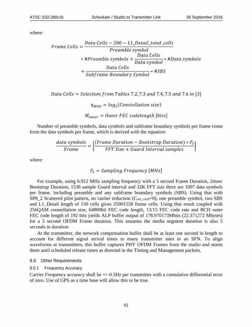
ATSC S32-266r16 Scheduler / Studio to Transmitter Link 30 September 2016
51
where:
𝐹𝐹𝐵𝐵𝐵𝐵𝐹𝐹𝐵𝐵 𝐶𝐶𝐵𝐵𝐶𝐶𝐶𝐶𝐶𝐶 =𝐷𝐷𝐵𝐵𝐵𝐵𝐵𝐵 𝐶𝐶𝐵𝐵𝐶𝐶𝐶𝐶𝐶𝐶 − 200 − 𝐵𝐵1_𝐷𝐷𝐵𝐵𝐵𝐵𝐵𝐵𝐷𝐷𝐶𝐶_𝐵𝐵𝑡𝑡𝐵𝐵𝐵𝐵𝐶𝐶_𝐵𝐵𝐵𝐵𝐶𝐶𝐶𝐶𝐶𝐶
𝑃𝑃𝐵𝐵𝐵𝐵𝐵𝐵𝐹𝐹𝑃𝑃𝐶𝐶𝐵𝐵 𝐶𝐶𝐵𝐵𝐹𝐹𝑃𝑃𝑡𝑡𝐶𝐶
∗ #𝑃𝑃𝐵𝐵𝐵𝐵𝐵𝐵𝐹𝐹𝑃𝑃𝐶𝐶𝐵𝐵 𝐶𝐶𝐵𝐵𝐹𝐹𝑃𝑃𝑡𝑡𝐶𝐶𝐶𝐶 +𝐷𝐷𝐵𝐵𝐵𝐵𝐵𝐵 𝐶𝐶𝐵𝐵𝐶𝐶𝐶𝐶𝐶𝐶𝐷𝐷𝐵𝐵𝐵𝐵𝐵𝐵 𝐶𝐶𝐵𝐵𝐹𝐹𝑃𝑃𝑡𝑡𝐶𝐶
∗ #𝐷𝐷𝐵𝐵𝐵𝐵𝐵𝐵 𝐶𝐶𝐵𝐵𝐹𝐹𝑃𝑃𝑡𝑡𝐶𝐶𝐶𝐶
+𝐷𝐷𝐵𝐵𝐵𝐵𝐵𝐵 𝐶𝐶𝐵𝐵𝐶𝐶𝐶𝐶𝐶𝐶
𝑆𝑆𝐵𝐵𝑃𝑃𝐵𝐵𝐵𝐵𝐵𝐵𝐹𝐹𝐵𝐵 𝐵𝐵𝑡𝑡𝐵𝐵𝐵𝐵𝐵𝐵𝐵𝐵𝐵𝐵𝐵𝐵 𝑆𝑆𝐵𝐵𝐹𝐹𝑃𝑃𝑡𝑡𝐶𝐶∗ #𝑆𝑆𝐵𝐵𝑆𝑆
𝐷𝐷𝐵𝐵𝐵𝐵𝐵𝐵 𝐶𝐶𝐵𝐵𝐶𝐶𝐶𝐶𝐶𝐶 = 𝑆𝑆𝐵𝐵𝐶𝐶𝐵𝐵𝐵𝐵𝐵𝐵𝐷𝐷𝑡𝑡𝐵𝐵 𝐵𝐵𝐵𝐵𝑡𝑡𝐹𝐹 𝑇𝑇𝐵𝐵𝑃𝑃𝐶𝐶𝐵𝐵𝐶𝐶 7.2, 7.3 𝐵𝐵𝐵𝐵𝐵𝐵 7.4, 7.5 𝐵𝐵𝐵𝐵𝐵𝐵 7.6 𝐷𝐷𝐵𝐵 [3]
𝜂𝜂𝑀𝑀𝑀𝑀𝑀𝑀 = 𝐶𝐶𝑡𝑡𝑙𝑙2(𝐶𝐶𝑡𝑡𝐵𝐵𝐶𝐶𝐵𝐵𝐵𝐵𝐶𝐶𝐶𝐶𝐵𝐵𝐵𝐵𝐷𝐷𝑡𝑡𝐵𝐵 𝐶𝐶𝐷𝐷𝑠𝑠𝐵𝐵)
𝑀𝑀𝑐𝑐𝑜𝑜𝑐𝑐𝑐𝑐𝑐𝑐 = 𝑂𝑂𝐵𝐵𝐵𝐵𝐵𝐵𝐵𝐵 𝐹𝐹𝐹𝐹𝐶𝐶 𝐵𝐵𝑡𝑡𝐵𝐵𝐵𝐵𝐶𝐶𝐵𝐵𝐵𝐵𝑙𝑙𝐵𝐵ℎ [𝑃𝑃𝐷𝐷𝐵𝐵𝐶𝐶]
Number of preamble symbols, data symbols and subframe boundary symbols per frame come from the data symbols per frame, which is derived with the equation:
𝐵𝐵𝐵𝐵𝐵𝐵𝐵𝐵 𝐶𝐶𝐵𝐵𝐹𝐹𝑃𝑃𝑡𝑡𝐶𝐶𝐶𝐶𝐹𝐹𝐵𝐵𝐵𝐵𝐹𝐹𝐵𝐵
= �(𝐹𝐹𝐵𝐵𝐵𝐵𝐹𝐹𝐵𝐵 𝐷𝐷𝐵𝐵𝐵𝐵𝐵𝐵𝐵𝐵𝐷𝐷𝑡𝑡𝐵𝐵 − 𝐵𝐵𝑡𝑡𝑡𝑡𝐵𝐵𝐶𝐶𝐵𝐵𝐵𝐵𝐵𝐵𝑡𝑡 𝐷𝐷𝐵𝐵𝐵𝐵𝐵𝐵𝐵𝐵𝐷𝐷𝑡𝑡𝐵𝐵) ∗ 𝐹𝐹𝑆𝑆
𝐹𝐹𝐹𝐹𝑇𝑇 𝑆𝑆𝐷𝐷𝑠𝑠𝐵𝐵 + 𝐺𝐺𝐵𝐵𝐵𝐵𝐵𝐵𝐵𝐵 𝐼𝐼𝐵𝐵𝐵𝐵𝐵𝐵𝐵𝐵𝐼𝐼𝐵𝐵𝐶𝐶 𝐶𝐶𝐵𝐵𝐹𝐹𝑡𝑡𝐶𝐶𝐵𝐵𝐶𝐶�
where:
𝐹𝐹𝑆𝑆 = 𝑆𝑆𝐵𝐵𝐹𝐹𝑡𝑡𝐶𝐶𝐷𝐷𝐵𝐵𝑙𝑙 𝐹𝐹𝐵𝐵𝐵𝐵𝐹𝐹𝐵𝐵𝐵𝐵𝐵𝐵𝐵𝐵𝐵𝐵 [𝑀𝑀𝑀𝑀𝑠𝑠]
For example, using 6.912 MHz sampling frequency with a 5 second Frame Duration, 2msec Bootstrap Duration, 1536 sample Guard interval and 32K FFT size there are 1007 data symbols per frame, including preamble and any subframe boundary symbols (SBS). Using that with SP8_2 Scattered pilot pattern, no carrier reduction (Cred_coeff=0), one preamble symbol, two SBS and L1_Detail length of 150 cells gives 25901558 frame cells. Using that result coupled with 256QAM constellation size, 64800bit FEC code length, 13/15 FEC code rate and BCH outer FEC code length of 192 bits yields ALP buffer output of 178.970173Mbits (22.371272 Mbytes) for a 5 second OFDM Frame duration. This assumes the media segment duration is also 5 seconds in duration.
At the transmitter, the network compensation buffer shall be at least one second in length to account for different signal arrival times to many transmitter sites in an SFN. To align waveforms at transmitters, this buffer captures PHY OFDM Frames from the studio and stores them until scheduled release times as directed in the Timing and Management packets.
8.5 Other Requirements 8.5.1 Frequency Accuracy Carrier Frequency accuracy shall be +/–0.5Hz per transmitter with a cumulative differential error of zero. Use of GPS as a time base will allow this to be true.

ATSC S32-266r16 Scheduler / Studio to Transmitter Link 30 September 2016
52
8.5.2 Timing Offsets To cause transmitters in a network to emit their waveforms at times needed for network shaping, offsets may be applied to emission time values individually at each transmitter. A transmitter timing reference with high precision, low jitter and zero long-term drift can be derived from a single reference and may be delivered to each site or derived at each site. Each transmitter must be locked to a source equal to GPS Time interval. It can be GPS time or TAI, but it must be independent of leap seconds.
Frequency reference with high precision, low jitter and zero long term drift can be derived from the timing reference. GPS-like sources can be available simultaneously at multiple locations at the studio and transmitter to enable this accurate reference.

ATSC S32-266r16 Scheduler / Studio to Transmitter Link, Annex A 30 September 2016
53
Annex A: Physical Layer Control
A.1 PHYSICAL LAYER RESOURCES System Manager pre-determined schedule consists of at least the control parameters listed in Section 9 of [3]. A list of the control inputs to the physical layer are in the following sub-sections. Dependency of some parameters may be based on others from a formula. Those will be identified when possible.
A.1.1 Bootstrap Signaling bootstrap_major_version – This parameter is defined by [2] and constrained by [3]. Intent is to
signal a structure change that is not backwards compatible with existing version(s) of the bootstrap.
bootstrap_minor_version – This parameter is defined by [2] and constrained by [3]. Intent is to signal a structure change that is backwards compatible with existing version(s) of the bootstrap.
ea_wake_up – This parameter is defined by [2] to signal an emergency alert. min_time_to_next – This parameter is defined by [2] to signal when a similar frame type (a frame
that matches the same major and minor version number as the current frame) will be available in an emission.
system_bandwidth – This parameter is defined by [2] to signal the channel bandwidth of the post-bootstrap portion of the current physical layer frame.
bsr coefficient – This parameter is defined by [2] and constrained by Table 9.1 in [3] with broadcaster intended baseband sample rate.
preamble structure – This parameter is defined by [2] and constrained by Table K.1.1 in [3] with settings for FFT size, guard interval and scattered pilot patterns for L1 Basic preamble symbols chosen by broadcaster. Preamble symbols should be at least as robust as the most robust payload settings.
A.1.2 L1-Basic Signaling L1B_content_tag – This parameter is defined by [3] and signals new information is available in L1
Detail. L1B_version – This parameter is defined and constrained by [3]. It is major version signaling of
the preamble L1-Basic signaling structure. L1B_slt_flag – This parameter is defined by [3] to signal if Service List Table (SLT) is available in
the current frame. SLT is defined by [4] and is the starting point for finding which services are available on a given broadcast channel.
L1B_time_info_flag – This parameter is defined by [3] to signal the presence of timing information in the current frame.
L1B_papr – This parameter is defined by [3] to signal the technique to reduce the peak to average power within the current frame.
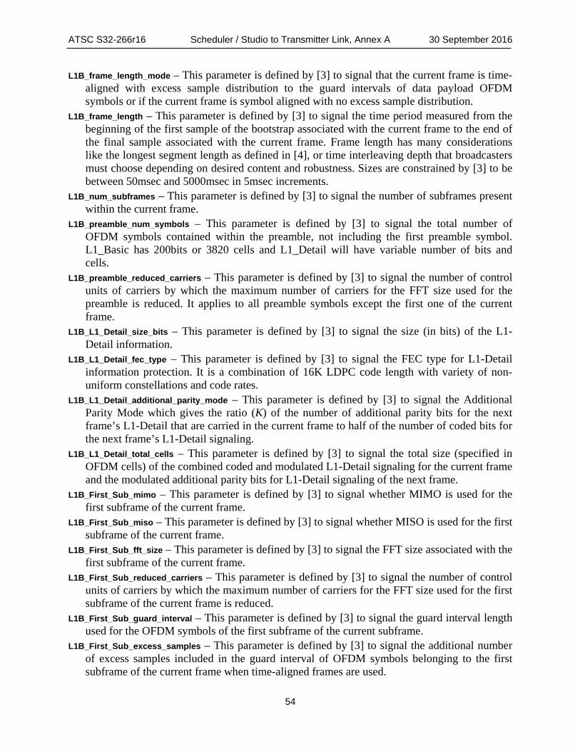
ATSC S32-266r16 Scheduler / Studio to Transmitter Link, Annex A 30 September 2016
54
L1B_frame_length_mode – This parameter is defined by [3] to signal that the current frame is time-aligned with excess sample distribution to the guard intervals of data payload OFDM symbols or if the current frame is symbol aligned with no excess sample distribution.
L1B_frame_length – This parameter is defined by [3] to signal the time period measured from the beginning of the first sample of the bootstrap associated with the current frame to the end of the final sample associated with the current frame. Frame length has many considerations like the longest segment length as defined in [4], or time interleaving depth that broadcasters must choose depending on desired content and robustness. Sizes are constrained by [3] to be between 50msec and 5000msec in 5msec increments.
L1B_num_subframes – This parameter is defined by [3] to signal the number of subframes present within the current frame.
L1B_preamble_num_symbols – This parameter is defined by [3] to signal the total number of OFDM symbols contained within the preamble, not including the first preamble symbol. L1_Basic has 200bits or 3820 cells and L1_Detail will have variable number of bits and cells.
L1B_preamble_reduced_carriers – This parameter is defined by [3] to signal the number of control units of carriers by which the maximum number of carriers for the FFT size used for the preamble is reduced. It applies to all preamble symbols except the first one of the current frame.
L1B_L1_Detail_size_bits – This parameter is defined by [3] to signal the size (in bits) of the L1-Detail information.
L1B_L1_Detail_fec_type – This parameter is defined by [3] to signal the FEC type for L1-Detail information protection. It is a combination of 16K LDPC code length with variety of non-uniform constellations and code rates.
L1B_L1_Detail_additional_parity_mode – This parameter is defined by [3] to signal the Additional Parity Mode which gives the ratio (K) of the number of additional parity bits for the next frame’s L1-Detail that are carried in the current frame to half of the number of coded bits for the next frame’s L1-Detail signaling.
L1B_L1_Detail_total_cells – This parameter is defined by [3] to signal the total size (specified in OFDM cells) of the combined coded and modulated L1-Detail signaling for the current frame and the modulated additional parity bits for L1-Detail signaling of the next frame.
L1B_First_Sub_mimo – This parameter is defined by [3] to signal whether MIMO is used for the first subframe of the current frame.
L1B_First_Sub_miso – This parameter is defined by [3] to signal whether MISO is used for the first subframe of the current frame.
L1B_First_Sub_fft_size – This parameter is defined by [3] to signal the FFT size associated with the first subframe of the current frame.
L1B_First_Sub_reduced_carriers – This parameter is defined by [3] to signal the number of control units of carriers by which the maximum number of carriers for the FFT size used for the first subframe of the current frame is reduced.
L1B_First_Sub_guard_interval – This parameter is defined by [3] to signal the guard interval length used for the OFDM symbols of the first subframe of the current subframe.
L1B_First_Sub_excess_samples – This parameter is defined by [3] to signal the additional number of excess samples included in the guard interval of OFDM symbols belonging to the first subframe of the current frame when time-aligned frames are used.

ATSC S32-266r16 Scheduler / Studio to Transmitter Link, Annex A 30 September 2016
55
L1B_First_Sub_num_ofdm_symbols – This parameter is defined by [3] to signal a value equal to one less than the total number of data payload OFDM symbols, including any subframe boundary symbol(s), present within the first subframe of the current frame.
L1B_First_Sub_scattered_pilot_pattern – This parameter is defined by [3] to signal the scattered pilot pattern used for the first subframe of the current subframe whether it is SISO or MIMO.
L1B_First_sub_scattered_pilot_boost – This parameter is defined by [3] to signal the amplitude of the scattered pilots used for the first subframe of the current frame.
L1B_First_Sub_sbs_first – This parameter is defined by [3] to signal whether or not the first symbol of the first subframe of the current frame is a subframe boundary symbol.
L1B_First_Sub_sbs_last – This parameter is defined by [3] to signal whether or not the last symbol of the first subframe of the current frame is a subframe boundary symbol.
A.1.3 L1-Detail signaling L1D_version – This parameter is defined by [3]. It signals the major version of the preamble L1-
Detail structure for the current frame. L1D_num_rf – This parameter is defined by [3] to signal the number of frequencies involved in
channel bonding of the current ATSC 3.0 system, not including the frequency of the present channel.
L1D_rf_id – This parameter is defined by [3] to signal the implicit IDs of the other RF channels involved in channel bonding.
L1D_rf_frequency – This parameter is defined by [3] to signal the center frequency (in 10 kHz units) of the other RF channel involved in channel bonding, associated with the implicit ID of L1D_rf_id.
(TBD) L1D_time_info – TG3 AHG on System Time will determine whether time information is sent in the preamble.
L1D_mimo – This parameter is defined by [3] to signal whether MIMO is used for a given subframe.
L1D_miso – This parameter is defined by [3] to signal whether MISO is used for a given subframe.
L1D_fft_size – This parameter is defined by [3] to signal the FFT size associated with the given subframe.
L1D_reduced_carriers – This parameter is defined by [3] to signal the number of control units of carriers by which the maximum number of carriers for the FFT size used for the given subframe is reduced.
L1D_guard_interval – This parameter is defined by [3] to signal the guard interval length used for the OFDM symbols of the given subframe.
L1D_num_ofdm_symbols – This parameter is defined by [3] to signal the value equal to one less than the total number of data payload OFDM symbols, including any subframe-opening/closing symbol(s), present within the given subframe.
L1D_scattered_pilot_pattern – This parameter is defined by [3] to signal the scattered pilot pattern used for the given subframe, whether it is SISO or MIMO.
L1D_scattered_pilot_boost – This parameter is defined by [3] to signal the amplitude of the scattered pilots used for the given subframe.
L1D_sbs_first – This parameter is defined by [3] to signal whether or not the first symbol of the given subframe is a subframe boundary symbol.

ATSC S32-266r16 Scheduler / Studio to Transmitter Link, Annex A 30 September 2016
56
L1D_sbs_last – This parameter is defined by [3] to signal whether or not the last symbol of the given subframe is a subframe boundary symbol.
L1D_subframe_multiplex – This parameter is defined by [3] to signal whether the given subframe is time-division multiplexed / concatenated in time with adjacent subframes.
L1D_frequency_interleaver – This parameter is defined by [3] to signal whether the frequency interleaver is enabled or bypassed for the given subframe.
L1D_num_plp – This parameter is defined by [3] to signal a value equal to one less than the total number of PLPs used within the given subframe.
L1D_plp_id – This parameter is defined by [3] to signal a value equal to the ID of the given PLP, with a range from 0 to 63, inclusive.
L1D_plp_slt_exist – This parameter is defined by [3] to signal whether the given PLP contains the service list table (upper layer information).
L1D_plp_size – This parameter is defined by [3] to signal a value equal to the number of data cells allocated to the given PLP.
L1D_plp_scrambler_type – This parameter is defined by [3] to signal the choice of scrambler type for the given PLP.
L1D_plp_fec_type – This parameter is defined by [3] to signal the Forward Error Correction (FEC) method used for encoding the given PLP.
L1D_plp_mod – This parameter is defined by [3] to signal the modulation used for the given PLP, whether SISO or MIMO.
L1D_plp_cod – This parameter is defined by [3] to signal the coding rate used for the given PLP. L1D_plp_TI_mode – This parameter is defined by [3] to signal the time interleaving mode for the
given PLP. The scheduler is responsible for selecting the appropriate time interleaver mode to use for each core-layer PLP configured for an RF channel.
L1D_plp_num_channel_bonded – This parameter is defined by [3] to signal the number of frequencies, not including the frequency of the present channel, involved in channel bonding of the given PLP.
L1D_plp_bonded_rf_id – This parameter is defined by [3] to signal the RF id(s) of the channel(s) that are used for channel bonding with the given PLP.
L1D_plp_channel_bonding_format – This parameter is defined by [3] to signal the channel bonding format for the given PLP, whether plain channel bonding or SNR averaging channel bonding.
L1D_plp_stream_combining – This parameter is defined by [3] to signal whether the stream combining option of the MIMO precoder is used in the given PLP.
L1D_plp_IQ_interleaving – This parameter is defined by [3] to signal whether the IQ polarization interleaving option of the MIMO precoder is used in the given PLP.
L1D_plp_PH – This parameter is defined by [3] to signal whether the phase hopping option of the MIMO precoder is used in the given PLP.
L1D_plp_start – This parameter is defined by [3] to signal a value equal to the index of the data cell that holds the first data cell of the current PLP in the given subframe.
L1D_plp_type – This parameter is defined by [3] to signal when the given PLP is non-dispersed (i.e. all data cells of the current PLP have contiguous logical addresses and subslicing is not used for the current PLP) or when the current PLP is dispersed (i.e. not all data cells of the current PLP have contiguous logical addresses and subslicing is used for the current PLP). If type has a value of one, the number of subslices and subslice interval are set.

ATSC S32-266r16 Scheduler / Studio to Transmitter Link, Annex A 30 September 2016
57
L1D_num_subslices – If the given PLP is dispersed, this parameter is defined by [3] to signal a value equal to the one less than the actual number of subslices used for the given PLP within the given subframe.
L1D_subslice_interval – If the given PLP is dispersed, this parameter is defined by [3] to signal a value equal to the number of sequentially-indexed data cells measured from the beginning of a subslice for a given PLP to the beginning of the next subslice for the same PLP.
L1D_plp_TI_extended_interleaving – This parameter is defined by [3] to signal whether extended interleaving is to be used for the given PLP.
L1D_CTI_depth – This parameter is defined by [3] to signal the number of rows used in the convolutional time interleaver, including the row without any delay.
If TI mode equals 01, CTI start row is signaled, else use Hybrid TI and set HTI inter subframe, HTI number of TI blocks, HTI number of FEC blocks max and HTI number of FEC blocks, along with HTI cell interleaver on / off.
L1D_CTI_start_row – This parameter is defined by [3] to signal the position of the interleaver selector at the start of the given subframe.
L1D_CTI_fecframe_start – This parameter is defined by [3] to signal the start position of the first complete FEC frame in the given subframe.
L1D_HTI_inter_subframe – This parameter is defined by [3] to signal the hybrid time interleaving mode for a given PLP.
L1D_HTI_num_ti_blocks – This parameter is defined by [3] to signal either the number of TI blocks per interleaving frame, NTI, when L1D_HTI_inter_subframe=0 or the number of subframes, PI, over which cells from one-TI block are carried when L1D_plp_HTI_inter_subframe=1 in a given PLP.
L1D_HTI_num_fec_blocks_max – This parameter is defined by [3] to signal a value one less than the maximum number of FEC blocks per interleaving frame for the given PLP.
L1D_HTI_num_fec_blocks – This parameter is defined by [3] to signal a value one less than the number of FEC blocks contained in the current interleaving frame for the given PLP.
L1D_HTI_cell_interleaver – This parameter is defined by [3] to signal whether the cell interleaver is used in a given PLP.
L1D_plp_layer – This parameter is defined by [3] to signal a value equal to the layer index of the given PLP.
L1D_ldm_injection_level – This parameter is defined by [3] to signal the enhanced layer injection level relative to the core layer. Text and illustrations

ATSC S32-266r16 Scheduler / Studio to Transmitter Link, Annex B 30 September 2016
58
Annex B Network Configuration Examples
B.1 EXAMPLE STUDIO NETWORK TOPOLOGIES For environments with a single ALP stream producer and consumer, simply connecting the two units with a cross-over cable would suffice. The network connections would have to be on the same subnet but would require no further setup. If the scheduler and framer were in separate physical boxes, as is implied by Figure 4.2, a simple network hub could be added as is depicted in Figure B.1.1. Note that Figure B.1.1 also shows using RTP/UDP/IP multicast to move various signaling, NRT data, audio and video components into a conceptual multiplexer. The multiplexer would remove the RTP headers prior to the ALP encapsulation stage, between the instances of ‘4’ in Figure B.1.1, since broadcast receivers do not support RTP as part of the emission standard. Using RTP allows the multiplexer to manage the order and timing of the contribution source streams. The sources also will supply timing information in the RTP streams to enable reconstruction of packet spacing within the ALP stream.
Figure B.1.1 Simple ALP encapsulation.
Figure B.1.2 shows a case in which separate A/V encoding systems are producing audio and video for two PLPs. In this example, a signaling system would produce signaling information that would be included in both PLP streams. Signaling could be included in either stream individually or in a dedicated PLP in the same manner. The NRT data generation system also would produce ROUTE streams that could be included in either or both PLPs as desired. In Figure B.1.2, NRT is only being included in PLP 1. Note that in this example, all streams are on separate multicast addresses on the input to the multiplexer. Under this proposal, the output of the multiplexer (5 & 6) would be on the same multicast address with different ports. Since there is only one source for each stream in this example, there is no need for IGMP SSM and all network connections can be accomplished with relatively inexpensive hubs or switches.

ATSC S32-266r16 Scheduler / Studio to Transmitter Link, Annex B 30 September 2016
59
Figure B.1.2 Multiple PLP example.
A more typical production situation is diagrammed in Figure B.1.3. This example shows a redundant encoding and signaling environment, redundant multiplexer and redundant output systems feeding into separate STLs (not shown). The multiplexers combine various ROUTE and/or MMTP multicasts into individual ALP streams, each destined for a unique PLP, removing RTP in the process. A single physical multiplexer likely would create multiple ALP streams for different PLPs but, functionally, each PLP stream can be considered separately.

ATSC S32-266r16 Scheduler / Studio to Transmitter Link, Annex B 30 September 2016
60
Figure B.1.3 Fully redundant routing example.
Note that none of the redundant systems needs to be aware of its counterpart. For example, A/V Encoder A (PLP 1) can be configured identically to A/V Encoder B (PLP 1) except, of course, for its network address. The emitted multicasts (in Figure B.1.3, the circled numbers {1} & {1'}) are identical in all aspects except that the UDP headers would contain different source addresses. Both MUX A (PLP 1) and MUX B (PLP 1) would be configured with the addresses of the PLP 1 A/V Encoders. Initially, they would both begin ALP encapsulation of A/V stream {1} into ALP streams {5} and {5'} by joining the multicast address and port using the address of the A/V Encoder A (PLP 1). If any problems were detected with {1} by either multiplexer, either would then switch to the second A/V stream, {1'}. This would be accomplished by simply leaving the IGMP multicast group for A/V Encoder A (PLP 1) {1} and ‘joining’ the A/V Encoder B (PLP 1) multicast {1'}. No other communication is required. Similarly, the {5} or {5'} ALP PLP 1 multicasts would feed both Scheduler/Framer subsystems based on joins from each. The Framer/Scheduler would necessarily need to know the source addresses of both Physical MUX A and B so that it could switch between the two sources if the quality of any of the streams degraded.

ATSC S32-266r16 Scheduler / Studio to Transmitter Link, Annex B 30 September 2016
61
Also note that a single router could be used to route all of the multicast traffic between each system. There are many options for duplicating routers and even having ring and tree configurations. Be aware that all multicast addresses would need to be unique within the broadcast plant network to enable a variety of routing options.
End of Document