Embed Size (px)
Citation preview

Atomic Layer Deposition of Lithium Tantalate Solid-StateElectrolytesJian Liu,† Mohammad N. Banis,† Xifei Li,† Andrew Lushington,† Mei Cai,‡ Ruying Li,† Tsun-Kong Sham,§
and Xueliang Sun*,†
†Department of Mechanical and Materials Engineering, University of Western Ontario, London, ON, Canada N6A 5B9‡General Motors R&D Center, Warren, Michigan 48090-9055, United States§Department of Chemistry, University of Western Ontario, London, ON, Canada N6A 5B7
*S Supporting Information
ABSTRACT: 3D all-solid-state microbatteries are promising onboard power systems for autonomous devices. The fabrication of3D microbatteries needs deposition of active materials, especially solid-state electrolytes, as conformal and pinhole free thin filmsin 3D architectures, which has proven very difficult for conventional deposition techniques, such as chemical vapor depositionand physical vapor deposition. Herein, we report an alternative technique, atomic layer deposition (ALD), for achieving idealsolid-state electrolyte thin films for 3D microbatteries. Lithium tantalate solid-state electrolytes, with well-controlled filmcomposition and film thickness, were grown by ALD at 225 °C using subcycle combination of 1 × Li2O + n × Ta2O5 (1 ≤ n ≤10). The film composition was tunable by varying Ta2O5 subcycles (n), whereas the film thickness displayed a linear relationshipwith ALD cycle number, due to the self-limiting nature of the ALD process. Furthermore, the lithium tantalate thin films showedexcellent uniformity and conformity in 3D anodic aluminum oxide template. Moreover, impedance testing showed that thelithium tantalate thin film exhibited a lithium ion conductivity of 2 × 10⁻⁸ S/cm at 299 K. The lithium tantalate thin films byALD, featured with well-controlled film thickness and composition, excellent step coverage, and moderate ionic conductivity atroom temperature, would be promising solid-state electrolytes for 3D microbatteries.
1. INTRODUCTIONMicroelectronic devices are becoming increasingly incorporatedinto our daily activities. A great deal of effort has been devotedto developing autonomous devices, such as medical implants,self-powered integrated circuits, and microelectromechanicalsystems, which need be driven by an on-board power supplysystem.1,2 Lithium-ion batteries (LIBs) are a preferable energymedium for these types of applications, due to their ability todeliver high energy density.2 In particular, all-solid-state LIBshave drawn great attention from various industries, since theycan permit greater flexibility in the design of batteries, provideimproved intrinsic safety due to the absence of liquidelectrolytes, and facilitate miniaturization of microelectronicdevices.1−3 During the past decade, research in the field of all-solid-state LIBs has been primarily focused on two-dimensional(2D) thin film batteries.4,5 However, it is becoming difficult for2D thin film batteries to meet the elevated power consumption
demand in modern microelectronic devices due to their limitedenergy density per unit area.2 One effective strategy to increasethe capacity per unit area (μA h cm−2) of all-solid-sate LIBs isdeveloping three-dimensional (3D) microbatteries instead of2D thin film batteries. 3D microbatteries can offer significantlyincreased specific surface area of active materials in the sameareal footprint as 2D thin film batteries and maintain short pathlengths for the diffusion of lithium ion, thereby renderinggreatly enhanced battery capacity per unit area.2,3 Given theadvantages and demand of 3D microbatteries, various conceptsfor their design have been proposed.1−3,6−9 However, it is stillchallenging to fabricate real 3D microbatteries, partly due to thegreat limitations of conventional deposition techniques
Received: June 26, 2013Revised: September 5, 2013Published: September 6, 2013
Article
pubs.acs.org/JPCC
© 2013 American Chemical Society 20260 dx.doi.org/10.1021/jp4063302 | J. Phys. Chem. C 2013, 117, 20260−20267

employed in the fabrication of 2D thin film batteries, such asphysical vapor deposition (PVD), chemical vapor deposition(CVD), and electrochemical deposition. One of the mostdifficult, but crucial, steps in the fabrication of 3D micro-batteries is the deposition of conformal and pinhole-free thinfilms onto 3D structures. The thin films required in 3Dmicrobatteries must be perfect and free of cracks or pinholes,which will result in short circuits and failure of batteries. It hasbeen realized that the key to achieving as-desired thin films in3D architectures is the use of a deposition technique that isinherently self-limiting.8,10
Atomic layer deposition (ALD) has been known as a thinfilm technique being capable of depositing high-quality films in3D structures.11 Unlike other film deposition methods, such asPVD or CVD, ALD employs self-limiting surface reactions viaalternating, saturated precursor doses.12,13 As a consequence,ALD provides exquisite control over the thickness of thin films,and the thin films deposited by ALD have excellentconformality and uniformity, even in 3D substrates with aspectratio in excess of 1000.14 These unique features make ALD asuitable technique for fabricating 3D microbatteries, and itspotential has been demonstrated recently.15−17 For example,anatase TiO2 thin film with 17 nm thickness was deposited byALD directly on aligned aluminum nanorods, which served ascurrent collectors.15 The 3D TiO2 nanoelectrode exhibited acapacity 10 times higher than traditional 2D TiO2 electrode inthe same areal footprint and showed excellent rate capabilityand stability in 50 charge−discharge cycling. V2O5 thin filmswere deposited using ALD on micropillars coated with TMV/Ni, forming hierarchical 3D electrodes.17 The conformal V2O5thin films on the 3D micropillar electrodes enabled muchhigher energy density and faster charge−discharge rate thanthose on a planar substrate. Even though no real 3Dmicrobatteries have been manufactured by ALD, given theaforementioned exclusive advantages, it is expected that ALDwill play an important role in fabricating 3D microbatteries inthe near future.In recent years, ALD has been widely applied in conventional
LIBs, either to directly prepare active materials (such as SnO2,Li4Ti5O12, V2O5)
18−22 or to coat the anode or cathodeelectrodes with metal oxides (such as Al2O3, ZrO2, ZnO)aiming at improving their performance.23−32 However, theapplication of ALD technique in 3D microbatteries is still rare.Advancement in the field of 3D microbatteries prepared byALD is highly reliant on the development of battery materials,i.e., anodes, solid-state electrolytes, and cathodes.33,34 SomeALD-derived materials (mainly metal oxide such as TiO2, SnO2,V2O5) have been directly adopted as anodes or cathodes in 3Dmicrobatteries.33,34 However, there have been very few reportson the synthesis of solid-state electrolytes by ALD.35−41 It wasnot until 2009 that research relevant to solid-state electrolytesdeposited by ALD started to emerge, when the ALD processfor Li2O was first investigated.35 Aaltonen et al.36 applied ALDto grow lithium lanthanum titanate (LLT) electrolytes at 225°C by combining subcycles of TiO2 (TiCl4−H2O), La2O3(La(thd)3−O3), and Li2O (LiOtBu−H2O). The LLT thinfilm deposited at saturation conditions had a composition ofLi0.32La0.30TiOz, with amorphous structure. The LLT thin filmwas crystallized after annealing at 800 °C in oxygen for 3 h.Later on, Li2O−Al2O3 thin films were fabricated by the samegroup using ALD of Li2O (LiOtBu−H2O) and Al2O3 (TMA−O3).
37 The thickness of the Li2O−Al2O3 thin film was found todepend on ALD cycles linearly, yielding a growth rate of 2.8 Å/
cycle. Hamalainen et al.38,39 described the deposition of lithiumphosphate and lithium silicate thin films by ALD. The lithiumphosphate was deposited between 225 and 350 °C usingtrimethyl phosphate and either of LiHMDS or LiOtBu, and thelithium silicate was grown in a temperature range of 150−400°C from LiHMDS and O3. In both cases, the growth rate andcomposition of the thin films were dependent on depositiontemperature. Furthermore, Li3N was deposited by ALD fromLiHMDS and NH3 at 167 °C, showing a growth rate of 0.95 Å/cycle.40 Even though progress on ALD synthesis of solid-stateelectrolytes has been made, investigation on their lithium-ionconductivity was seldom conducted. Only Aaltonen et al.37
presented a lithium-ion conductivity of 1 × 10⁻⁷ S/cm (at 300°C) for Li2O−Al2O3 thin film, which had been annealed at 700°C for 5 h. Unfortunately, the high operating temperature andpostannealing requirement seriously hinder application of theLi2O−Al2O3 thin film. The postannealing process increases therisk of cracking in solid-state electrolytes, leading to shortcircuits and failure of 3D microbatteries. Therefore, it isessential that the solid-state electrolyte thin films are preparedin a “gentle” manner to avoid cracking.To fulfill the objective above, lithium tantalate was selected
as the solid-state electrolyte to be deposited by ALD in thiswork. Lithium tantalate has the following advantages: (1) Beinglithium-ion conductive with amorphous structure. Previouswork has found that amorphous phase of lithium tantalaterather than crystalline one was conductive of lithium ions.42,43
The ALD-deposited lithium tantalate would show a disorderedstructure due to the low deposition temperature (225 °C) usedherein.35−39 It was expected that the lithium tantalate grown byALD could be a lithium-ion conductor at the as-depositedcondition, saving post-treatment process and avoiding possiblecracking of thin films during this process. (2) Displayingacceptable lithium-ion conductivity (10−5−10−8 S/cm). (3)Negligible electronic conductivity at room temperature.42,43 Insummary, this work realized the deposition of lithium tantalatethin films by ALD technique, for the first time. The synthesizedlithium tantalate thin films were featured with not onlyprecisely controlled film thickness, but well-tuned filmcomposition. Most importantly, the lithium tantalate thinfilms by ALD, at the as-deposited state, exhibited moderatelithium-ion conductivity at room temperature, with norequirement of further treatments. Furthermore, the ALDapproach reported herein could achieve uniform and conformallithium tantalate thin films in a 3D architecture. It is believedthat the lithium tantalate thin films deposited by ALD wouldhave great potential as solid-state electrolytes in 3D micro-batteries.
2. EXPERIMENTAL SECTIONAll lithium tantalate thin films were deposited at 225 °C in aSavannah 100 ALD system (Cambridge Nanotech Inc.) bycombining ALD subcycles of Li2O and Ta2O5. The Li2Osubcycle consisted of alternating pulses of lithium tert-butoxide(LiOtBu, (CH3)3COLi) and H2O, while the Ta2O5 subcycleconsisted of alternating pulses of tantalum(V) ethoxide(Ta(OEt)5, Ta(OC2H5)5) and H2O. The source temperaturesfor LiOtBu, Ta(OEt)5, and H2O were 170, 190, and 23 °C,respectively. The system pipelines were heated to 190 °C inorder to prevent condensation of the precursors. The pulsetimes of LiOtBu and Ta(OEt)5 were varied from 0.2 to 1.5 s,while the pulse time of H2O remained at 1 s. All precursorpulses were separated by a 10 s nitrogen purge. One ALD cycle
The Journal of Physical Chemistry C Article
dx.doi.org/10.1021/jp4063302 | J. Phys. Chem. C 2013, 117, 20260−2026720261

was executed using a pulsing sequence of 1 × [LiOtBu (0.2−1.5s)−purge (10 s)−H2O (1 s)−purge (10 s)]-n × [Ta(OEt)5(0.2−1.5 s)−purge (10 s)−H2O (1 s)−purge (10 s)], whichwas expressed as 1 × Li2O + n × Ta2O5 (1 ≤ n ≤ 10) in brief.All lithium tantalate thin films were deposited on planar Si(100) and glass substrates. Anodic aluminum oxide (AAO,Anodisc 13, Whatman) template with aspect ratio of ∼300 waschosen as a 3D substrate. All characterizations were carried outon the Si (100) substrate except otherwise noted.After ALD coatings, the Si (100) substrate was cut into small
pieces. One piece of Si (100) with fresh surface was chosen andpasted onto a vertical SEM holder using carbon slurry. Thethicknesses of the lithium tantalate thin films were measuredfrom the fresh cross sections of the Si (100) using field-emission scanning electron microscopy (SEM, Hitachi-4800).The thicknesses of the thin films were obtained by takingaverage of 10 values measured at different locations of eachsample. The compositions of the lithium tantalate thin filmswere analyzed by using X-ray photoelectron spectroscopy(XPS) using Kratos Axis Ultra Al (alpha) spectrometer. Thephases of the lithium tantalate thin films on the glass substratewere identified using micro-X-ray diffraction (XRD, Bruker D8,Co Kα source, λ = 1.7892 Å). The Ta L3 edge X-ray absorptionnear-edge structure (XANES) measurements were performedon the 06ID superconducting wiggler hard X-ray microanalysis(HXMA) beamline at the Canadian Light Source (CLS) with apremirror−double crystal monochromator−postmirror config-uration using Si (111) crystals and Rh mirrors. CLS operates at2.9 GeV with 175 mA injection current and the beamlinewiggler was running at 1.5 T. Measurements were made atroom temperature in transmission mode for Ta foil with ionchambers filled with 100% of N2 and in fluorescence mode forthe lithium tantalate thin films using a 32-element Ge detector.To prepare the sample for impedance testing, ∼50 nm Au
layer was first sputtered on the glass substrate in a Polaronsputtering system under 2 kV for 9 min, and then the lithiumtantalate thin film was deposited on top of the Au layer using apulsing sequence of 400 × (1 × Li2O + 6 × Ta2O5). Followingthe ALD deposition, the as-prepared sample was immediatelytransferred into the Polaron sputtering system for coating ofanother Au layer (∼50 nm in thickness). The thickness of thelithium tantalate thin film (or the distance between the two Aulayers) was measured to be ∼200 nm, and the area of lithiumtantalate thin film was 5 mm × 5 mm. The impedance spectraat different temperatures were obtained by applying 50 mV in afrequency range of 200 kHz−10 Hz on a CHI electrochemistryworkstation. The sample was left to stabilize at eachtemperature for 30 min before acquiring data.
3. RESULTS AND DISCUSSIONFigures 1a and 1b show the effect of LiOtBu and Ta(OEt)5pulse times on the growth per cycle (GPC) of the lithiumtantalate system deposited using a pulsing sequence of (1 ×Li2O + 1 × Ta2O5). It can be seen that the GPC stabilizes ataround 2.1 Å/cycle, when pulse times for Ta(OEt)5 and LiO
tBuare longer than 0.5 and 1 s, respectively. Thus, Ta(OEt)5 andLiOtBu pulse lengths of 0.5 and 1 s, respectively, are sufficientto achieve saturated growth of the lithium tantalate thin film,and are chosen to be employed in subsequent experiments.The lithium tantalate thin films are deposited using pulsing
sequences of 1 × Li2O + n × Ta2O5 (n = 1, 6, and 10), wheresubcycle number of Ta2O5 (n) is varied in order to change filmcomposition (Li/Ta ratio). The morphologies of the as-
deposited thin films are examined by SEM. Figure 2 displaysthe result of the lithium tantalate thin film deposited using a
pulsing sequence of 1 × Li2O + 6 × Ta2O5 as an example. Fromtop-view observation in Figure 2a, it can be seen that 400-cyclelithium tantalate thin film is uniformly coated on the whole Sisubstrate, with a slight roughness associated with the filmsurface (Figure 2b). Cross-sectional views in Figure 2c clearlyshow the thicknesses of the lithium tantalate thin filmsdeposited with different ALD cycles (low-magnification imagesincluded in Figure SI-1 of the Supporting Information). Thethickness measurements by SEM are plotted as a function ofALD cycle number in Figure 3. XRD analysis (Figure SI-2)reveals amorphous structure of the as-grown lithium tantalatethin films.Figure 3a shows the ALD-cycle dependence of lithium
tantalate film thickness when different pulsing sequences areemployed. It is clear that the lithium tantalate film thickness islinearly dependent with ALD cycle, demonstrating the self-limiting behavior during the ALD process. By fitting the data inFigure 3a linearly, the GPC of the lithium tantalate thin film iscalculated to be 2.2, 5.2, and 7.3 Å/cycle, where n equals to 1, 6,and 10, respectively, in one (1 × Li2O + n × Ta2O5) cycle (asplotted in Figure 3b). From Figure 3b, one can see that theGPC of the lithium tantalate thin films increases monotonously
Figure 1. Growth per cycle of the lithium tantalate thin film as afunction of (a) Ta(OEt)5 pulse time and (b) LiOtBu pulse time usinga pulsing sequence of 400 × (1 × Li2O + 1 × Ta2O5).
Figure 2. SEM morphology of lithium tantalate thin film depositedusing a pulsing sequence of (1 × Li2O + 6 × Ta2O5): (a, b) top view of400-cycle thin film and (c) cross-section views of the thin filmsdeposited with different ALD cycles.
The Journal of Physical Chemistry C Article
dx.doi.org/10.1021/jp4063302 | J. Phys. Chem. C 2013, 117, 20260−2026720262

with Ta2O5 subcycle number (n) in one complete ALD cycle (1× Li2O + n × Ta2O5). This trend indicates that the GPC of thelithium tantalate thin films is a linear combination of the GPCof the Li2O subcycle and Ta2O5 subcycle. Thereby, twoparameters could be extracted from the best-linear-fit in Figure3b: the slope represents the GPC of the Ta2O5 subcycle (∼0.5Å/cycle), while the y-axis intercept of the linear fit representsthe GPC of solely the Li2O subcycle (∼1.7 Å/cycle). The GPCof the Li2O and Ta2O5 subcycles obtained herein have goodagreement with reported valves of Li2O at 1.7 Å/cycle37 andTa2O5 at 0.4 Å/cycle.44 A better understanding of the ALDprocess can be derived from looking at the reaction mechanismfor each subcycle. As proposed by Aaltonen et al.,37 during theLi2O subcycle, the LiOtBu pulse leads to the formation of twolayers, resulting in a high GPC of the Li2O subcycle:
− * + → − − * +OH LiOC(CH ) O Li HOC(CH )3 3 3 3 (1)
− − * + → − − − *O Li LiOC(CH ) O( Li) LiOC(CH )3 3 3 3(2)
where an asterisk denotes surface species. During the waterpulse, the surface species generated in eq 2 are converted tohydroxide groups:37,45
− − − * + → − − − *
+
O( Li) LiOC(CH ) H O O( Li) LiOH
HOC(CH )3 3 2
3 3 (3)
During the Ta2O5 subcycle, the following surface reactionoccurs:46
− * + →
− − * +−
n
n
( OH) Ta(OC H )
( O ) Ta(OC H ) HOC Hn n
2 5 5
2 5 5 2 5 (4)
− − * + −
→ − − * + −−
−
n
n
( O ) Ta(OC H ) (5 )H O
( O ) Ta(OH) (5 )HOC Hn n
n n
2 5 5 2
5 2 5 (5)
Therefore, the surface reactions during one complete (1 ×Li2O + n × Ta2O5) cycle would occur in the followingsequence:
One can find that the film surfaces after Li2O and Ta2O5subcycles are terminated with the same functional groups(−OH). Thus, the surface species available after each Li2Osubcycle are readily reactive sites for the succeeding Ta2O5subcycle, and vice versa. This condition ensures that the Li2Oand Ta2O5 subcycles in the combined ALD process proceed in
the same manner as in each binary oxide, therefore leading tothe similar GPC of Li2O and Ta2O5 in the ternary system as ineach binary system. The self-limiting characteristic of the Li2Oand Ta2O5 subcycles takes responsibility for the linearrelationship between the lithium tantalate film thickness andALD cycles (Figure 3a) and between the GPC of the lithiumtantalate films on Ta2O5 subcycle number (Figure 3b). It isworth mentioning that in a ternary or quaternary systemdeposited by ALD, the GPC of the combined oxide processes isusually lower than what is expected from a linear combinationof the GPC of each binary oxide.36,47 For example, the averageGPC of La−Ti−O films grown by combining La2O3 and TiO2subcycles was found to be below the theoretical GPC calculatedfrom individual growth rate of La2O3 (0.28 Å/cycle) and TiO2(0.52 Å/cycle).36 The reason was most likely due to thedifference in the surface chemistry between the preceding andthe succeeding subcycles, which could alter the GPC of one oreach binary system when they are combined. This differencewas more obvious in the Li−La−Ti−O system, which wasfabricated using Li2O, La2O3, and TiO2 subcycles. It was foundthat the pulsing order of the three subcycles had a substantialinfluence on the Li−La−Ti−O films. The film grown by using asequence of TiO2−La2O3−Li2O was less rough and moreuniform than that deposited using a TiO2−Li2O−La2O3 pulsingsequence.36 Thus, precursor combination and pulsing sequenceshould be carefully selected when depositing thin filmscomposed of two or more ALD subcycles. From the calculationin Figure 3b, one can find that the GPC of the Ta2O5 subcycle(∼0.5 Å/cycle) is slightly higher than that of binary Ta2O5 (0.4Å/cycle) reported in the literature.44 The higher GPC of Ta2O5in our case might be due to denser regeneration of hydroxidegroups after each Li2O subcycle (eq 3) than those producedafter each Ta2O5 subcycle (eq 5). Another reason that cannotbe excluded is the possibility of physisorbed water remaining onthe surface after reaction 3 and/or reaction 5. Physisorbedwater may lead to CVD-like growth of thin film during theTa(OEt)5 pulse, thus leading to a higher GPC of Ta2O5 thanexpected.The structure of amorphous materials is difficult to
determine by diffraction-based techniques due to the lack oflong-range order. By contrast, X-ray spectroscopy is sensitive tothe local environment of the element to be examined and thusis ideal and powerful for analyzing amorphous materials.48 Bycomparing the X-ray spectra of unknown and referencematerials, it is possible to gain insight into the structure ofnoncrystalline materials.48,49 Thus, XANES and XPS techniqueswere employed to study the structure or/and composition ofthe amorphous lithium tantalate thin films deposited by ALD inthis work. Figure 4 displays XANES at Ta L3 edge for thelithium tantalate thin films, in comparison with referencecrystalline LiTaO3 and pure Ta. The peak at the L3 edge arisesfrom Ta 2p3/2 to unoccupied Ta 5d states via dipole transition,and its intensity is expected to be higher in LiTaO3 and exhibitsa blue shift since Ta is in a higher oxidation state (d chargedepletion). In Figure 4, it can be seen that all the lithiumtantalate thin films have very similar Ta L3-edge spectrum toreference LiTaO3, except that the lithium tantalate thin filmsexhibit one broad peak at ∼9886.5 eV, instead of two well-resolved peaks at 9884.5 and 9886.8 eV for reference crystallineLiTaO3.
50 This slight difference is attributable to theamorphous state of the lithium tantalate thin films.51,52 InFigure 4, it is also obvious that the Ta L3-edge XANES of thelithium tantalate thin films are remarkably different from that of
Figure 3. (a) Thickness of the lithium tantalate thin films as a functionof ALD cycle number and (b) the growth per cycle of the lithiumtantalate thin films as a function of Ta2O5 subcycle number, usingpulsing sequences of 1 × Li2O + n × Ta2O5 (n = 1, 6, and 10).
The Journal of Physical Chemistry C Article
dx.doi.org/10.1021/jp4063302 | J. Phys. Chem. C 2013, 117, 20260−2026720263

pure Ta metal as expected. The XANES result indicates that theTa in lithium tantalate thin films have similar chemical binding(Li−O−Ta) as that in reference LiTaO3 with a noticeablebroadening due to disorder.Compositions of the lithium tantalate thin films were
analyzed by XPS, and the results are displayed in Figure 5.The XPS survey in Figure 5a indicates the presence of Li, Ta,and O elements in all the lithium tantalate thin films (theiratomic percentages listed in SI-Table 1). The chemical formulais determined as Li12.3TaOz, Li5.1TaOz, and Li0.6TaOz, for thelithium tantalate thin film deposited using a Ta2O5 subcyclenumber of 1, 6, and 10, respectively, while Li2O was keptconstant at 1. XPS data reveal that the Li/Ta ratio of thelithium tantalate thin films decreases with increasing Ta2O5subcycle number, as plotted in Figure 5b. Figure 5c illustratesthe chemical environment of Ta element in the lithiumtantalate thin films by analyzing the Ta 4f spectrum. ForLi12.3TaOz and Li5.1TaOz, the Ta 4f spectrum is fitted into oneset of doublet Ta 4f5/2 (peak A) and Ta 4f7/2 (peak B). Thepositions of Ta 4f5/2 (peak A) and Ta 4f7/2 (peak B) arecentered at 27.7 and 25.8 eV for Li12.3TaOz and at 27.9 and 26.0eV for Li5.1TaOz, respectively. The slight shift of Ta 4f5/2 (peakA) and Ta 4f7/2 (peak B) is due to the stoichiometry changefrom Li12.3TaOz to Li5.1TaOz. The positions of the Ta 4f5/2(peak A) and Ta 4f7/2 (peak B) are very close to those reportedin stoichiometric LiTaO3 film,53 revealing that the Ta inLi12.3TaOz and Li5.1TaOz has a similar chemical binding (Li−O−Ta) as stoichiometric LiTaO3. Deconvolution of Ta 4f peak
of Li0.6TaOz is composed of two pairs of doublets. The one pairof Ta 4f5/2 (peak A) and Ta 4f7/2 (peak B) at lower bindingenergy are consistent with those in Li5.1TaOz. The other pair ofTa 4f5/2 (peak A′) and Ta 4f7/2 (peak B′) at higher bindingenergy are located at 29.2 and 27.3 eV, respectively, which seemsimilar to the binding energy of Ta in stoichiometric Ta2O5.
54
This result indicates that the Ta element in Li0.6TaOz exists intwo types of chemical environments, i.e., Li−O−Ta and Ta−O−Ta, which make up 82% and 18%, respectively. Theappearance of Ta−O−Ta obviously resulted from the moreTa2O5 subcycles employed during the deposition of Li0.6TaOz.Besides the above elements, carbon is also detected in all thinfilms prepared (Figure 5a). The presence of carbon can beaddressed to organic carbons in C−C, C−H (284.8 eV), C−OH, C−O−C (286.3 eV), O−CO (288.8 eV), and CO(287.2 eV) (see Figure SI-3). The source of carbon is a result ofligand residue of ALD precursors as well as hydrocarbonspresent in ambient air.55 In Li12.3TaOz, another major source ofcarbon impurity is carbonate (290.1 eV) (Figure SI-3), which iscommonly found in lithium-containing thin films produced byALD.37,55 Carbonate present results from a reaction betweenLi2O and ambient carbon dioxide when the thin films areexposed to air45 and thereby should predominantly reside onthe topmost surface of the thin film.37,55 In Li5.1TaOz andLi0.6TaOz, carbonate only accounts for 4−6% of the carbonimpurity compared to 40% in Li12.3TaOz (Figure SI-3). Thisdifference could be explained by the fact that more Ta2O5subcycles were used in ALD process of Li5.1TaOz and Li0.6TaOzthan Li12.3TaOz, and resultant thicker Ta2O5 layer in the formerfilms can better prevent the reaction of Li2O with ambientcarbon dioxide. Li5.1TaOz thin film is chosen to be furtherstudied in terms of the lithium-ion conductivity because it isstable in air and easy for operation. More importantly, theexcess Li content in Li5.1TaOz thin film is beneficial for lithium-ion conduction according to previous studies.53,56
Lithium-ion conductivity of 400-cycle Li5.1TaOz thin film(∼200 nm thick) was assessed by using electrochemicalimpedance spectroscopy. Figure 6a shows Cole−Cole plots ofthe Li5.1TaOz thin film measured at different temperatures. Itcan be seen that each Cole−Cole plot consists of one semicirclein the high-frequency region and an inclined tail in the low-frequency region. The former semicircle could be assigned tothe bulk resistance of Li5.1TaOz solid-state electrolyte,42 whilethe latter is attributable to the polarization at electrode−electrolyte interface.57 It is worth noting that the inclined tail in
Figure 4. Ta L3-edge XANES spectra of lithium tantalate thin filmsdeposited using pulsing sequences of 1 × Li2O + n × Ta2O5 where (a)n = 1, (b) n = 6, and (c) n = 10, (d) reference crystalline LiTaO3, and(e) pure Ta.
Figure 5. (a) XPS survey of the lithium tantalate thin films deposited using pulsing sequences of 1 × Li2O + n × Ta2O5 (n = 1, 6, and 10), (b) Li/Taratio in the thin films as a function of Ta2O5 subcycle number (n), and (c) deconvolution of Ta 4f spectra. In (c), the components A and A′correspond to the Ta 4f5/2 lines, and the components B and B′ correspond to the Ta 4f7/2 lines.
The Journal of Physical Chemistry C Article
dx.doi.org/10.1021/jp4063302 | J. Phys. Chem. C 2013, 117, 20260−2026720264
the case of ionic blocking electrodes (such as Au used herein) istypical indication that the investigated solid-state electrolyte ispredominately ionic conductor in nature.57,58 The Cole−Coleplots could be well-resolved using the equivalent circuit inset inFigure 6a, in which Rb and C represent the bulk resistance andthe resultant capacitance of the Li5.1TaOz solid-state electrolyte,respectively, Zin denotes the polarization impedance of theelectrode−electrolyte interface, and Ro is the ohmic resistanceof the electrodes.42 Rb values are obtained in Figure 6a atdifferent temperatures, and the ionic conductivity of theLi5.1TaOz solid-state electrolyte is derived from the equation59
σ = d AR/ b (6)
where σ is the ionic conductivity, d is the thickness of theLi5.1TaOz film, and A is the area of the Li5.1TaOz film betweenAu electrodes. The ionic conductivity of Li5.1TaOz varies from1.2 × 10−8 to 9.0 × 10⁻⁷ S/cm, at temperatures between 299and 373 K. Furthermore, variation of the ionic conductivitywith temperature is shown in an Arrhenius representationaccording to59,60
σ σ= −T E kTexp[ /( )]0 a (7)
where Ea denotes the activation energy, k is the Boltzmannconstant, T is the absolute temperature, and σ0 is a constant.Activation energy of ∼0.55 eV is obtained by fitting thetemperature dependence of the lithium-ion conductivity inFigure 6b. Comparisons are made between Li5.1TaOz, LixTaOyprepared by RF sputtering and Li2O−Al2O3 grown by ALD inTable 1. It can be found that the lithium-ion conductivity ofLi5.1TaOz (2 × 10⁻⁸ S/cm at 299 K) is comparable with that ofamorphous LixTaOy prepared by RF sputtering (8 × 10⁻⁸ S/cmat 300 K).42 For the Li2O−Al2O3, its lithium-ion conductivitywas estimated to be around 1 × 10⁻⁷ S/cm at 573 K, and nodata at room temperature was reported.37 Furthermore, theLi2O−Al2O3 exhibits a much higher activation energy (2.9 eV)than Li5.1TaOz (0.55 eV) and amorphous LixTaOy (0.25 eV).The lithium-ion conductivity of Li5.1TaOz is considerably lowcompared with popular solid-state electrolytes (such asNASICON-type, Garnet-type)61,62 deposited by the PVDmethod in 2D batteries. However, these popular solid-state
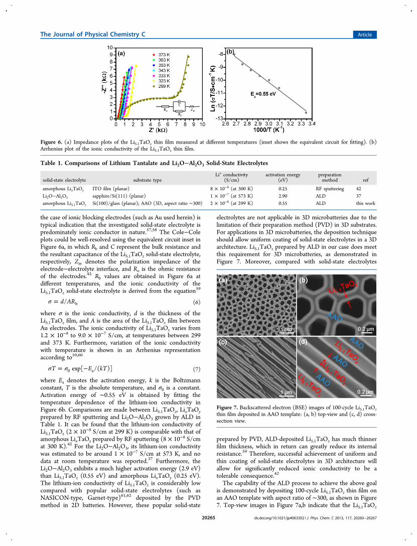
electrolytes are not applicable in 3D microbatteries due to thelimitation of their preparation method (PVD) in 3D substrates.For applications in 3D microbatteries, the deposition techniqueshould allow uniform coating of solid-state electrolytes in a 3Darchitecture. Li5.1TaOz prepared by ALD in our case does meetthis requirement for 3D microbatteries, as demonstrated inFigure 7. Moreover, compared with solid-state electrolytes
prepared by PVD, ALD-deposited Li5.1TaOz has much thinnerfilm thickness, which in return can greatly reduce its internalresistance.59 Therefore, successful achievement of uniform andthin coating of solid-state electrolytes in 3D architecture willallow for significantly reduced ionic conductivity to be atolerable consequence.42
The capability of the ALD process to achieve the above goalis demonstrated by depositing 100-cycle Li5.1TaOz thin film onan AAO template with aspect ratio of ∼300, as shown in Figure7. Top-view images in Figure 7a,b indicate that the Li5.1TaOz
Figure 6. (a) Impedance plots of the Li5.1TaOz thin film measured at different temperatures (inset shows the equivalent circuit for fitting). (b)Arrhenius plot of the ionic conductivity of the Li5.1TaOz thin film.
Table 1. Comparisons of Lithium Tantalate and Li2O−Al2O3 Solid-State Electrolytes
solid-state electrolyte substrate typeLi+ conductivity
(S/cm)activation energy
(eV)preparationmethod ref
amorphous LixTaOy ITO film (planar) 8 × 10⁻⁸ (at 300 K) 0.25 RF sputtering 42Li2O−Al2O3 sapphire/Si(111) (planar) 1 × 10⁻⁷ (at 573 K) 2.90 ALD 37amorphous Li5.1TaOz Si(100)/glass (planar); AAO (3D, aspect ratio ∼300) 2 × 10⁻⁸ (at 299 K) 0.55 ALD this work
Figure 7. Backscattered electron (BSE) images of 100-cycle Li5.1TaOzthin film deposited in AAO template: (a, b) top-view and (c, d) cross-section view.
The Journal of Physical Chemistry C Article
dx.doi.org/10.1021/jp4063302 | J. Phys. Chem. C 2013, 117, 20260−2026720265

thin film is uniformly and conformally coated around the poresof the AAO template. Furthermore, cross-section examination,as seen in Figure 7c,d, shows that the inner surface of the poresis covered by a tubular thin film of Li5.1TaOz. The thickness ofthe Li5.1TaOz thin film is measured as ∼50 nm from the top(Figure 7b) and the side (Figure 7d). The BSE images inFigure 7 clearly illustrate that the ALD process developedherein is capable of depositing desirable lithium tantalate thinfilms in high-aspect-ratio substrates, as required in 3Dmicrobatteries.
4. CONCLUSION
Lithium tantalate thin films have been deposited by means ofALD through combining subcycles of Li2O (LiOtBu−H2O) andTa2O5 (Ta(OEt)5−H2O). All lithium tantalate thin films weredeposited at 225 °C, and they were amorphous at as-depositedstate. The growth of the lithium tantalate thin films by ALDwas proven to be a self-limiting process. Composition (Li/Taratio) of the lithium tantalate thin films was controlled bychanging the subcycle ratios of Li2O to Ta2O5 (1 to 1, 1 to 6,and 1 to 10). Both XPS and XANES analysis confirmed that Tain the lithium tantalate thin films had similar chemicalenvironment as that in reference LiTaO3. The as-grown lithiumtantalate thin film using 1 Li2O and 6 Ta2O5 subcycles exhibiteda lithium-ion conductivity of 2 × 10⁻⁸ S/cm at roomtemperature. Moreover, the ALD process developed in thiswork successfully deposited lithium tantalate thin films withexcellent uniformity and conformality in a 3D AAO templatewith an aspect ratio of ∼300. Given the aforementioned uniqueadvantages, the lithium tantalate thin films prepared by ALDmight find potential applications as solid-state electrolytes in3D lithium-ion microbatteries, which is very promising powersupply system for next-generation microelectronic devices.
■ ASSOCIATED CONTENT
*S Supporting InformationLow-magnification SEM images of the lithium tantalate thinfilm deposited using pulsing sequence of 1 × Li2O + 6 × Ta2O5with different ALD cycles; XRD pattern of 400-cycle lithiumtantalate thin film deposited using pulsing sequence of 1 ×Li2O + 6 × Ta2O5 on the glass substrate; deconvolution of C1s/4 spectrum of the lithium tantalate thin films depositedusing different pulsing sequences; elemental compositions oflithium tantalate thin films deposited using different pulsingsequences as measured by XPS. This material is available free ofcharge via the Internet at http://pubs.acs.org.
■ AUTHOR INFORMATION
Corresponding Author*Tel + 1 519 661 2111 x87759; fax + 1 519 661 3020; [email protected] (X.S.).
NotesThe authors declare no competing financial interest.
■ ACKNOWLEDGMENTS
This work was supported by General Motors of Canada,Natural Sciences and Engineering Research Council of Canada(NSERC), Canada Fundation for Innovation (CFI), OntarioResearch Fund (ORF), Canadian Light Source (CLS) atUniversity of Saskatchewan, and University of Western Ontario.
■ REFERENCES(1) Long, J. W.; Dunn, B.; Rolison, D. R.; White, H. S. Three-Dimensional Battery Architectures. Chem. Rev. 2004, 104, 4463−2292.(2) Roberts, M.; Johns, P.; Owen, J.; Brandell, D.; Edstrom, K.;Enany, G. E.; Guery, C.; Golodnitsky, D.; Lacey, M.; Lecoeur, C.; et al.3D Lithium Ion Batteries−from Fundamentals to Fabrication. J. Mater.Chem. 2011, 21, 9876−9890.(3) Oudenhoven, J. F. M.; Baggetto, L.; Notten, P. H. L. All-Solid-State Lithium-Ion Microbatteries: a Review of Various Three-Dimensional Concepts. Adv. Energy Mater. 2011, 1, 10−33.(4) Bates, J. B.; Dudney, N. J.; Neudecker, B.; Ueda, A.; Evans, C. D.Thin-Film Lithium and Lithium-Ion Batteries. Solid State Ionics 2000,135, 33−45.(5) Souquet, J. L.; Duclot, M. Thin Film Lithium Batteries. Solid StateIonics 2002, 148, 375−379.(6) Arthur, T. S.; Bates, D. J.; Cirigliano, N.; Jhonson, D. C.; Malati,P.; Mosby, J. M.; Perre, E.; Rawls, M. T.; Prieto, A. L.; Dunn, B. Three-Dimensional Electrodes and Battery Architectures. MRS Bull. 2011,36, 523−531.(7) Notten, P. H. L.; Roozeboom, F.; Niessen, R. A. H.; Baggetto, L.3-D Integrated All-Solid-State Rechargeable Batteries. Adv. Mater.2007, 19, 4564−4567.(8) Dunn, B.; Long, J. W.; Rolison, D. R. Rethinking Multifunction inThree Dimensions for Miniaturizing Electrical Energy Storage.Electrochem. Soc. Interface 2008, 17, 49−53.(9) Golodnitsky, D.; Nathan, M.; Yufit, V.; Strauss, E.; Freedman, K.;Burstein, L.; Gladkich, A.; Peled, E. Progress in Three-Dimensional(3D) Li-Ion Microbatteries. Solid State Ionics 2006, 177, 2811−2819.(10) Rolison, D. R.; Long, J. W.; Lytle, J. C.; Fischer, A. E.; Rhodes,C. P.; Mcevoy, T. M.; Bourg, M. E.; Lubers, A. M. Multifunctional 3DNanoarchitectures for Energy Storage and Conversion. Chem. Soc. Rev.2009, 38, 226−252.(11) Bae, C.; Shin, H.; Nielsch, K. Surface Modification andFabrication of 3D Nanostructures by Atomic Layer Deposition. MRSBull. 2011, 36, 887−897.(12) George, S. M. Atomic Layer Deposition: an Overview. Chem.Rev. 2010, 110, 111−131.(13) Puurunen, R. L. Surface Chemistry of Atomic Layer Deposition:a Case Study for the Trimethylaluminum/Water Process. J. Appl. Phys.2005, 97, 121301.(14) Elam, J. W.; Routkevitch, D.; Mardilovich, P. P.; George, S. M.Conformal Coating on Ultrahigh-Aspect-Ratio Nanopores of AnodicAlumina by Atomic Layer Deposition. Chem. Mater. 2003, 15, 3507−3517.(15) Cheah, S. K.; Perre, E.; Rooth, M.; Fondell, M.; Harsta, A.;Nyholm, L.; Boman, M.; Gustafsson, T.; Lu, J.; Simon, P.; et al. Self-Supported Three-Dimensional Nanoelectrodes for MicrobatteryApplications. Nano Lett. 2009, 9, 3230−3233.(16) Gerasopoulos, K.; Chen, X.; Culver, J.; Wang, C.; Ghodssi, R.Self-Assembled Ni/TiO2 Nanocomposite Anode Synthesized viaElectroless Plating and Atomic Layer Deposition on BiologicalScaffolds. Chem. Commun. 2010, 46, 7349−7351.(17) Gerasopoulos, K.; Pomerantseva, E.; McCarthy, M.; Brown, A.;Wang, C.; Culver, J.; Ghodssi, R. Hierarchical Three-DimensionalMicrobattery Electrodes Combining Bottom-Up Self-Assembly andTop-Down Micromachining. ACS Nano 2012, 6, 6422−6432.(18) Li, X.; Meng, X.; Liu, J.; Geng, D.; Zhang, Y.; Banis, M. N.; Li,Y.; Yang, J.; Li, R.; Sun, X.; et al. Tin Oxide with ControlledMorphology and Crystallinity by Atomic Layer Deposition ontoGraphene Nanosheets for Enhanced Lithium Storage. Adv. Funct.Mater. 2012, 22, 1647−1654.(19) Chen, X.; Pomerantseva, E.; Banerjee, P.; Gregorczyk, K.;Ghodssi, R.; Rubloff, G. Ozone-Based Atomic Layer Deposition ofCrystalline V2O5 for High Performance Electrochemical EnergyStorage. Chem. Mater. 2012, 24, 1255−1261.(20) Meng, X.; Liu, J.; Li, X.; Banis, M. N.; Yang, J.; Li, R.; Sun, X.Atomic Layer Deposited Li4Ti5O12 on Nitrogen-Doped CarbonNanotubes. RSC Adv. 2013, 3, 7285−7288.
The Journal of Physical Chemistry C Article
dx.doi.org/10.1021/jp4063302 | J. Phys. Chem. C 2013, 117, 20260−2026720266

(21) Kim, S. W.; Han, T. H.; Kim, J.; Gwon, H.; Moon, H. S.; Kang,S. W.; Kim, S. O.; Kang, K. Fabrication and ElectrochemicalCharacterization of TiO2 Three-Dimensional Nanonetwork Basedon Peptide Assembly. ACS Nano 2009, 3, 1085−1090.(22) Meng, X.; Zhong, Y.; Sun, Y.; Banis, M. N.; Li, R.; Sun, X.Nitrogen-Doped Carbon Nanotubes Coated by Atomic LayerDeposited SnO2 with Controlled Morphology and Phase. Carbon2011, 49, 1133−1144.(23) Scott, I. D.; Jung, Y. S.; Cavanagh, A. S.; Yan, Y.; Dillon, A. C.;George, S. M.; Lee, S.-H. Ultrathin Coatings on Nano-LiCoO2 for Li-Ion Vehicular Applications. Nano Lett. 2011, 11, 414−418.(24) Guan, D.; Jeevarajan, J. A.; Wang, Y. Enhanced Cycleability ofLiMn2O4 Cathodes by Atomic Layer Deposition of Nanosized-ThinAl2O3 Coatings. Nanoscale 2011, 3, 1465−1469.(25) Zhao, J.; Qu, G.; Flake, J. C.; Wang, Y. Low TemperaturePreparation of Crystalline ZrO2 Coatings for Improved Elevated-Temperature Performance of Li-Ion Battery Cathodes. Chem.Commun. 2012, 48, 8108−8110.(26) Jung, Y. S.; Cavanagh, A. S.; Riely, L. A.; Kang, S.-H.; Dillon, A.C.; Groner, M. D.; George, S. M.; Lee, S.-H. Ultrathin Direct AtomicLayer Deposition on Composite Electrodes for Highly Durable andSafety Li-Ion Batteries. Adv. Mater. 2010, 22, 2172−2176.(27) Zhao, J.; Wang, Y. Ultrathin Surface Coatings for ImprovedElectrochemical Performance of Lithium Ion Battery Electrodes atElevated Temperature. J. Phys. Chem. C 2012, 116, 11867−11876.(28) Ann, D.; Xiao, X. Extended Lithium Titanate Cycling PotentialWindow with Near Zero Capacity Loss. Electrochem. Commun. 2011,13, 796−799.(29) Liu, J.; Li, X.; Cai, M.; Li, R.; Sun, X. Ultrathin Atomic LayerDeposited ZrO2 Coating to Enhance the Electrochemical Performanceof Li4Ti5O12 as an Anode Material. Electrochim. Acta 2013, 93, 195−201.(30) H, Y.; Yu, X.; Wang, Y.; Li, H.; Huang. Alumina-CoatedPatterned Amorphous Silicon as the Anode for a Lithium-Ion Batterywith High Coulombic Efficiency. Adv. Mater. 2011, 23, 4938−4941.(31) Xiao, X.; Lu, P.; Ahn, D. Ultrathin Multifunctional OxideCoatings for Lithium Ion Batteries. Adv. Mater. 2011, 23, 3911−3915.(32) Riely, L. A.; Cavanagh, A. S.; George, S. M.; Jung, Y. S.; Yan, Y.;Lee, S.-H.; Dillon, A. C. Conformal Surface Coatings to Enhance HighVolume Expansion Li-Ion Anode Materials. ChemPhysChem 2010, 11,2124−2130.(33) Meng, X.; Yang, X.-Q.; Sun, X. Emerging Applications ofAtomic Layer Deposition for Lithium-Ion Battery Studies. Adv. Mater.2012, 24, 3589−3615.(34) Knoops, H. C. M.; Donders, M. E.; van de Sanden, M. C. M.;Notten, P. H. L.; Kessels, W. M. M. Atomic Layer Deposition forNanostructured Li-Ion Batteries. J. Vac. Sci. Technol., A 2012, 30,010801.(35) Putkonen, M.; Aaltonen, T.; Alnes, M.; Sajavaara, T.; Nilsen, O.;Fjellvag, H. Atomic Layer Deposition of Lithium Containing ThinFilms. J. Mater. Chem. 2009, 19, 8767−8771.(36) Aaltonen, T.; Alnes, M.; Nilsen, O.; Costelle, L.; Fjellvag, H.Lanthanum Titanate and Lithium Lanthanum Titanate Thin FilmsGrown by Atomic Layer Deposition. J. Mater. Chem. 2010, 20, 2877−2881.(37) Aaltonen, T.; Nilsen, O.; Magraso, A.; Fjellvag, H. Atomic LayerDeposition of Li2O-Al2O3 Thin Films. Chem. Mater. 2011, 23, 4669−4675.(38) Hamalainen, J.; Holopainen, J.; Munnik, F.; Hatanpaa, T.;Heikkila, M.; Ritala, M.; Leskela, M. Lithium Phosphate Thin FilmsGrown by Atomic Layer Deposition. J. Electrochem. Soc. 2012, 159,A259−A263.(39) Hamalainen, J.; Munnik, F.; Hatanpaa, T.; Holopainen, J.;Ritala, M.; Leskela, M. Study of Amorphous Lithium Silicate ThinFilms Grown by Atomic Layer Deposition. J. Vac. Sci. Technol., A 2012,30, 01A106.(40) Østreng, E.; Vajeeston, P.; Nilsen, O.; Fjellvag, H. Atomic LayerDeposition of Lithium Nitride and Carbonate Using LithiumSilylamide. RSC Adv. 2012, 2, 6315−6322.
(41) Comstock, D. J.; Elam, J. W. Mechanistic Study of LithiumAluminum Oxide Atomic Layer Deposition. J. Phys. Chem. C 2013,117, 1677−1683.(42) Glass, A. M.; Nassau, K.; Negran, T. J. Ionic Conductivity ofQuenched Alkali Niobate and Tantalate Glasses. J. Appl. Phys. 1978,49, 4808−4811.(43) Li, Z.; Chen, X.; Hu, X. The Preparation of Ionic Conductanceof Nano-Amorphous LixTaOy Thin Film. J. Phys. D: Appl. Phys. 1996,29, 2740−2744.(44) Kukli, K.; Ritala, M.; Leskela, M. Atomic Layer Epitaxy Growthof Tantalum Oxide Thin Films from Ta(OC2H5)5 and H2O. J.Electrochem. Soc. 1995, 142, 1670−1675.(45) Cavanagh, A. S.; Lee, Y.; Yoon, B.; George, S. M. Atomic LayerDeposition of LiOH and Li2CO3 Using Lithium t-Butoxide as theLithium Source. ECS Trans. 2010, 33, 223−229.(46) Kukli, K.; Aarik, J.; Aidla, A.; Siimon, H.; Ritala, M.; Leskela, M.In Situ Study of Atomic Layer Epitaxy Growth of Tantalum OxideThin Films from Ta(OC2H5)5 and H2O. Appl. Surf. Sci. 1997, 112,236−242.(47) Nilsen, O.; Rauwel, E.; Fjellvag, H.; Kjekshus, A. Growth ofLa1‑xCaxMnO3 Thin Films by Atomic Layer Deposition. J. Mater.Chem. 2007, 17, 1466−1475.(48) Gaultois, M. W.; Grosvenor, A. P. XANES and XPSInvestigations of the Local Structure and Final-State Effects inAmorphous Metal Silicates: (ZrO2)x(TiO2)y(SiO2)1‑x‑y. Phys. Chem.Chem. Phys. 2012, 14, 205−217.(49) Yang, S.; Wang, D.; Liang, G.; Yiu, Y. M.; Wang, J.; Liu, L.; Sun,X.; Sham, T.-K. Soft X-Ray XANES Studies of Various Phases Relatedto LiFePO4 Based Cathode Materials. Energy Environ. Sci. 2012, 5,7007−7016.(50) Kim, T. W.; Hur, S. G.; Han, A. R.; Hwang, S.-J.; Choy, J.-H.Effect of Bond Covalency on the Lattice Stability and Fatigue Behaviorof Ferroelectric Bismuth Transition-Metal Oxides. J. Phys. Chem. C2008, 112, 3434−3438.(51) Hu, Y. F.; Xu, R. K.; Dynes, J. J.; Blyth, R. I. R.; Yu, G.; Kozak, L.M.; Huang, P. M. Coordination Nature of Aluminum (Oxy)hydroxidesFormed Under the Influence of Tannic Acid Studied by X-RayAbsorption Spectroscopy. Geochim. Cosmochim. Acta 2008, 72, 1959−1969.(52) Liu, J.; Tang, Y.; Xiao, B.; Sham, T.-K.; Li, R.; Sun, X. AtomicLayer Deposited Aluminum Phosphate Thin Films on N-DopedCNTs. RSC Adv. 2013, 3, 4492−4495.(53) Gitmans, F.; Sitar, Z.; Gunter, P. Growth of Tantalum Oxideand Lithium Tantalate Thin Films by Molecular Beam Epitaxy.Vacuum 1995, 46, 939−942.(54) Atanassova, E.; Tyuliev, G.; Paskaleva, A.; Spassov, D.; Kostov,K. XPS Study of N2 Annealing Effect on Thermal Ta2O5 Layers on Si.Appl. Surf. Sci. 2004, 225, 86−99.(55) Miikkulainen, V.; Nilsen, O.; Laitinen, M.; Sajavaara, T.;Fjellvag, H. Atomic Layer Deposition of LixTiyOz Thin Films. RSCAdv. 2013, 3, 7537−7542.(56) Glass, A. M.; Nassau, K. Lithium Ion Conduction in RapidlyQuenched Li2O-Al2O3, Li2O-Ga2O3, and Li2O-Bi2O3 Glasses. J. Appl.Phys. 1980, 51, 3756−3761.(57) Huanosta, A.; West, A. R. The Electrical Properties ofFerroelectric LiTaO3 and Its Solid Solutions. J. Appl. Phys. 1987, 61,5386−5391.(58) Murugan, R.; Thangadurai, V.; Weppner, W. Fast Lithium IonConduction in Garnet-Type Li7La3Zr2O12. Angew. Chem. Int. Ed. 2007,46, 7778−7781.(59) Goodenough, J. B. Solid Electrolytes. Pure Appl. Chem. 1995, 67,931−938.(60) West, A. R. Solid Electrolytes. Ber. Bunsenges. Phys. Chem. 1989,93, 1235−1241.(61) Takada, K. Progress and Prospective of Solid-State LithiumBatteries. Acta Mater. 2013, 61, 759−770.(62) Thangadurai, V.; Weppner, W. Recent Progress in Solid Oxideand Lithium Ion Conducting Electrolytes Research. Ionics 2006, 12,81−92.
The Journal of Physical Chemistry C Article
dx.doi.org/10.1021/jp4063302 | J. Phys. Chem. C 2013, 117, 20260−2026720267


![Atomic layer deposition onto polymer surfaces · Atomic layer deposition (ALD) is a layer-by-layer process based on self-limiting gas-solid surface reactions [1-3]. Deposition cycles](https://img.dokumen.tips/doc/110x75/5f70f4ce86c8b13d2031a5ca/atomic-layer-deposition-onto-polymer-surfaces-atomic-layer-deposition-ald-is-a.jpg)