Embed Size (px)
Citation preview

MedizinTechnik
ATMOS Cam 21 / 31 Cam 21 / 31 DVENT Camera
Ope
ratin
g in
stru
ctio
ns
ATMOS MedizinTechnikGmbH & Co. KG
Ludwig-Kegel-Straße 12,14-16,1879853 Lenzkirch/Germany
Tel. +49 7653 / 689-0Fax +49 7653 / 689-190
English
REF 531.2010.BREF 531.2120.BREF 507.4100.BREF 531.4120.BREF 531.2080.BREF 531.2070.BREF 531.2090.BREF 507.5100.BREF 507.5130.BREF 507.5140.BREF 531.2065.BREF 531.2055.BREF 507.5110.BREF 507.5120.B
2010-12 Index: 10

ATMOSMedizinTechnik GmbH & Co. KGLudwig-Kegel-Straße 12-14-16,1879853 LenzkirchDeutschland/ Germany
Tel. +49 7653 689-0Fax: +49 7653 689-190 +49 7653 689-493 (Service Center)
Further information, accessories, consumables and spare parts are available from:

3
1.0 Introduction ............................................................................ 51.1 Notes on operating instructions 51.2 Intended use 51.3 Function 51.4 Explanation of symbols 62.0 For your safety ....................................................................... 73.0 Setting up and starting .......................................................8-93.1 Scope of supply 8-93.2 Connections 8-93.3 Digital monitor outlet 103.4 Installation 103.5 Fitting the holder for camera head 103.5.1 Connection diagram ATMOS Cam 21 / 31 DATA and ATMOS Strobo 21 LED 114.0 Operation............................................................................... 124.1 Power on/off 124.2 Application parts and light sources 124.3 Camera head 134.3.1 Inserting / replacing the application parts 134.3.2 Focussing / image definition 134.3.3 Digital zoom 134.4 Memory mode (only with Cam 31) 144.4.1 Storage of examination image 144.4.2 Switching amongst the modi 144.5 LED light sources (optional) 154.6 Manual white balance 154.6.1 White balance 154.6.2 Erasure of white balance 155.0 Cleaning ................................................................................ 165.1 General information on cleaning and disinfection 165.2 Unit surface 165.3 Camera head with video adapter 165.4 Chemical disinfection 165.5 Surface disinfectants 176.0 Repairs and servicing .......................................................... 186.1 Replacing the fuse 186.2 Regular safety relevant inspections 187.0 Trouble-shooting .................................................................. 198.0 Accessories and spare parts list ...................................20-218.1 Accessories 20-218.2 Options 218.3 Spare parts 219.0 Technical specifications ...................................................... 2210.0 Disposal ................................................................................ 2311.0 Arrangement ......................................................................... 2411.1 Connection possibilities 2412.0 Notes on EMC ....................................................................25-28 Declaration of conformity 29
Table of contents

4
ATMO
S C
am 21
ATMO
S C
am 31
ATMO
S C
am 31
Data
ATMO
S C
am 21 D
V
ATMO
S C
am 31 D
V
ATMO
S C
am 21 D
V D
ata
ATMO
S C
am 31 D
V D
ata
Image Memory: - - -
Digital Zoom: 1,7 2,0 2,0 1,7 2,0 1,7 2,0
Outputs:FBAS
SVHS
DVI-I - - - -
SXGA - - - -
Digital DV:Firewire (IEEE 1394)
- - -
Display of symbols
- - - -
Compared to the ATMOS Cam 21, the ATMOS Cam 31 has an additional image memory and a different zoom factor (2.0 instead of 1.7).
The DV versions have an IEEE 1394 outpus (FireWire) and in addition DVI-I and SXGA monitor outputs.
Information on the device versions

5
1.1 Notes on operating instructions
1.3 Function1.2 Intended use
→ The ATMOS Cam 21 / 31 is an ENT camera for displaying an examination image on a screen.
Visualization:
Duration of application:
Application:
Operation:
Explosion- hazardous areas:
Application area:
→ The camera is destined for being attached on all established ENT endoscopes as well as on a microscope.
→ In clinics and in ENT practices.
→ The duration of application (application on patient) is set as „temporary„ (up to 60 minutes).
→ Only trained personnel is meant for operation and application of the camera.
→ Not provided for usage in explosion- hazardous areas.
The ATMOS Cam 21 / 31 consists of a camera head and the unit itself. Both elements are connected detachably via a cable of 3 m length.The camera head contains a ⅓“ CCD colour image sensor with micro lenses and the facility for connecting standard endoscopes.
1.0 Introduction
These operating instructions contain important notes on how to operate the ATMOS Cam 21 / 31 safely, correctly and effectively. Their reading helps to avoid risks, and also to reduce repair costs and down-time. That increases, amongst other things, the reliability and service-life of the device.These operating instructions serve not only for new operating personnel to be instructed in its use, but also for use as a reference manual. Reprints (also in extracts) only with permission in written form by ATMOS.These operating instructions must always be kept available near the device.
Care and safety inspections in conjunction with professional execution provide for operational safety and readiness for use of your ATMOS Cam 21 / 31 and are therefore a must besides regular clea-ning. Repair work and safety inspections may be carried out only by expert personnel authorised by ATMOS. By applying only original spare parts you will have the guarantee that operational safety, readiness for work and the value of your ATMOS Cam 21 / 31 will be preserved.
The product ATMOS Cam 21 / 31 bears CE marking CE according to the EU guideline of the council for medical products 93/42/EWG and meets the basic requirements of annex I of this guideline. The quality management system applied at ATMOS has been certified according to international standards EN ISO 9001 and EN ISO 13485. Prior to start-up please peruse chapter 2.0 „For your safety“, in order to be prepared for any possible dangerous situations.
The camera can directly be connected to a computer due to the IEEE 1394 interface and the audio-in and therefore a transmission in digital format is possible. This means that our system seems to act like a DV camcorder. For this reason it can be connected to computers and MAC with fi rewire interface without any additional hardware. There are no ATMOS nor other drivers needed because the current Windows operating systems as well as Linux and Apple systems already have the necessary functionality.
Only applicable for ATMOS Cam 21 / 31 DV
In the following all device versions, as well as all modules and table-top devices are named ATMOS Cam 21 / 31!

6
!
→
~
clickclick
1.4 Explanation of pictures and symbols
Pictures contained in this manual
Foot switch Off (feed-in, power connection)
On (feed-in, power connection)
Alternating current
Ground wire connection
Control panel buttons of ATMOS Cam 21 / 31
EndoscopeUsage: Examination of nose and earstyp. ø : 2.7 and 4 mm respectivelytyp. angles: 0°, 30°, 45°, 70°
Flexible endoscopeUsage : Nose-, throat-, larynx examinations
LaryngoscopeUsage: Laryngeal examinationstyp. ø : 10 mmtyp. angles: 70°/90°
MicroscopeUsage: Examinatin of ears
Xenon light sourceTypical : 180W and 300W resp.Colour temperature: 5600...5800K
LED light sourceTypical: 2W (e.g. ATMOS LED light source and LED headlight )→ q.v. Accessories chapter 8.0
Stroboscope fl ashlight sourceUsage : Laryngo-stroboscopyColour temperature: 5800K
Halogen light sourceTypical: 150W and 250W resp.Colour temperature: 3200K
Warning, especial diligent notice
Application part type BF
Fuse according toIEC 417/5016, DIN 30600/0186
Potential equalization
1.0 Introduction
Short cuts / symbols contained in this manual
Please press where the dot indicates
Subnumeration
Numeration
General informationFollow the arrows whilst proceeding, sequence
Activate the optional foot switch Replace
CheckPlease read, important information
Move, plug ... in this direction
Engage, check correct fi t
Turn, shift ... in this direction
Valid for ATMOS Cam 21 / 31 DV
IEEE 1394 Digital Interface
Interlink / Data
Y/C / FBAS
Audio

7
!
The ATMOS Cam 21 / 31 is: → designed in line with IEC 601 / EN 60601. → assigned to VDE safety class I → assigned to class I of the German law on medical products.
2.0 For your safety
Please not unconditionally!
The ATMOS Cam 21 / 31 meets the immu- nity to interference requirements of IEC 601-1-2 / EN 60601-1-2 „Electromagnetic Compatibility – Medical Electrical Devices“.
No warranty rights shall exist in the event of damage or failure caused by the use of non-ATMOS accessories or non- ATMOS consumables.
Pay also attention to the safety informa- tion of the attached devices / parts as well as to the safety informations in the follo- wing chapters
General safety information
Danger of injury!
Danger to the device!
The ATMOS Cam 21 / 31 may only be used under the supervision of skilled staff who have been authorised by ATMOS and trained in its operation (IEC 601-1 / EN 60601-1).
The use of accessories not recommended by ATMOS may lead to fl ickering or image failures. These operating instructions correspond to the design of the device and the status of basic safety engineering standards on going to print. Please check the delivery on complete- ness and intactness.
ATMOS will not be liable for damage to people or property if: → Any non-original ATMOS parts are used. → The instructions for use contained in these operating instructions have been disregarded. → Assembly, resetting, alterations, extensions and repairs have not been carried out by people authorised by ATMOS.
To avoid injuries, please note the following details: Never touch the device´s interfaces and the patient at the same time.
Prior to fi rst starting up, all connecting leads must be checked on damage. Dama- ged cables must be replaced!
To disconnect the device from the mains supply, fi rst remove the plug from the wall outlet. Then separate the connecting cable from the device. Never touch plug or cable with wet hands! Prior to cleaning, switch off the device and separate it from the mains supply resp. from other devices. Ambient conditions: The ATMOS Cam 21 / 31 may be opera- ted only in rooms used for medical pur- poses, but not in areas subject to explo- sion hazards. Explosion hazards may result from the use of combustible ana- esthetic agents, skin cleansing agents or disinfectants.
The ATMOS Cam 21 / 31 may not be operated with devices not complying with the requirements of standard EN 60601-1 „Medical Electrical Equipment“ and EN 60601-1-2 „Electromagnetic Compati- bility“ (Medical Electrical Equipment).
The device may only be connected to a properly installed protective contact so- cket.
For mains supply, only use the power cable supplied (or an equivalent one).
Pay attention to the ambient conditions specifi ed in chapter 9.0.
Prior to fi rst starting up, check whether the mains voltage specifi ed on the type plate matches the local mains voltage.
Check proper assignment when assemb- ling country-specifi c connections: green / yellow: non-fused earth conductor blue: neutral conductor black or brown: phase
Protect the device against direct solar radi- ation and keep it away from heaters.
Please note: A medical insulating transformer with earth leakage monitor or any similar safety system acc. to EN 60 601-1 is required, if several devices are connect- ed over one common power supply. The transformer must correspond to the power consumption of all the devices to be connected.
When connecting several devices on one grounding receptacle, the allowed strain and leakage current have to be observed!
The lens of the focusing optic should be protected against mechanical contact.
Warning notice The cameras ATMOS Cam 31 DV and ATMOS Cam 21 DV have a digital monitor outlet with SXGA signal. The resolution is 1280 x 1024 pixels.
Please make sure that only monitors are connected which support the stated resolution. Otherwise the camera and/or monitor could get damaged.

8
3.0 Setting up and starting
Valid for ATMOS Cam 21 / 31
AB
3.1 Scope of supply
3.2 Connections
Forefront
Connection for Camera headConnection for LED light source
Control panel
Buttons for selecting application part and light source
Mains on/off switch
Arrangement q.v. Chapter.11.0, p. 22
Patientat least 1.5 m
distance from video components, which do not correspond to EN 60601-1
To guarantee preferably short facilities, place the video components (recorder, printer, monitor, etc.) at an immedate area to the ATMOS Cam 21 / 31. Please pay attention to operate all video components from one mains voltage distributor.
Non-medical products
All additional equipment which is connected to the analog and digital interfaces of the device must meet the re quirements of relevant EN specifications (for inst. EN 60950 for data processing equipment and EN 60601 for electrical medical appliances). In addition, configurations must satisfy system specification EN 60601-1-1:2001. When additional equipment is connected to the signal input or signal output section on the device, the person carrying out the connection is deamed „a system configuration operator“ and as such is responsible for meeting the requirements of system specification EN 60601-1-1:2001. For answers to additional questions, please contact your local specialist supplier or the ATMOS Technical Service.
Scope of supply
ATMO
S Cam
21
ATMO
S Cam
21 DV
ATMO
S Cam
21 DV D
ata
ATMO
S Cam
31
ATMO
S Cam
31 Data
ATMO
S Cam
31 DV
ATMO
S Cam
31 DV D
ata
Camera housing
Holder fpr Camera head
Camera head
footswitch to image memory
Data transfer cable RS 422
Audio for stroboscope Audiochannel incl. adapter plug
S-VHA Videocable
DV-Cable PC 6/6 pole (Firewire)
DV-Cable Laptop 6/4 pole (Firewire)
9
Connection for Camera head
AB
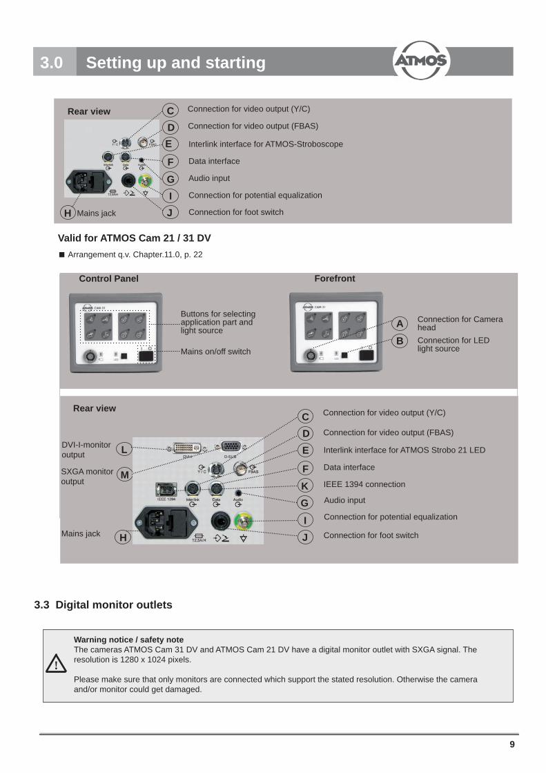
3.0 Setting up and starting
Forefront
Connection for Camera headConnection for LED light source
Control Panel
Buttons for selecting application part and light source
Mains on/off switch
Arrangement q.v. Chapter.11.0, p. 22
Valid for ATMOS Cam 21 / 31 DV
G
E
F
DC
IH
Rear view
Mains jack
Audio input
Data interface
Interlink interface for ATMOS-Stroboscope
Connection for video output (Y/C)
Connection for video output (FBAS)
Connection for potential equalization
J Connection for foot switch
M
DC
HIJ
GK
Rear view
Mains jack
Data interface
Interlink interface for ATMOS Strobo 21 LED
Connection for video output (Y/C)
Connection for video output (FBAS)
IEEE 1394 connection
Audio input
Connection for foot switch
Connection for potential equalization
LDVI-I-monitor output
SXGA monitor output
E
F
Warning notice / safety noteThe cameras ATMOS Cam 31 DV and ATMOS Cam 21 DV have a digital monitor outlet with SXGA signal. The resolution is 1280 x 1024 pixels.
Please make sure that only monitors are connected which support the stated resolution. Otherwise the camera and/or monitor could get damaged.
!
3.3 Digital monitor outlets

10
3.0 Setting up and starting
Y / C
3
A B1 2
I
....
K
clickclickclick
+.....
Please pay attention, just to switch on the devices after they have been completely wired.If required, analogue peripheral video equipment (monitor, video printer, etc) must be adjusted to NTSC video norm. For further details please look at the corresponding operating instructions.
3.5 Installation
Optional:
...or
3.4 Fitting the holder for camera head (not applicable for ATMOS Roadster)
Insertion like application part q.v. page 12,
chapter 4.3.2
Cable IEEE 1394
G
4
Valid for ATMOS Cam 21/31 DV
Connection for video output (Y/C)(S-VHS)
Connection for video output (FBAS) (VHS)
DVI-I-monitor output
SXGA monitoroutput (VGA) M D
CL
Optional:
...or
output L
output (VGA) M
Valid for ATMOS Cam 31

11
Valid for ATMOS Cam 21/31 DV
ATM
OS
Cam
21
/ 31
DV
DAT
AAT
MO
S St
robo
21
LED
21
1
11
507.
4260
.0 (6
/4)
507.
4261
.0 (6
/6)
008.0635.0
008.0635.0
011.
1293
.0
008.
0859
.0
008.
0858
.0
507.
4750
.0
507.
5016
.0
008.0858.0
008.
0858
.0
3.0 Setting up and startup3.5.1 Connection Diagram ATMOS Cam 21 / 31 Data and ATMOS Strobo 21 LED
Foot
Reg
ulat
or
Han
dle
Sup
port
LED
Lig
htso
urce
AT
MO
S S
trobo
LE
D
Ana
logu
e Vi
deo
Sys
tem
V
HS
/ S
-VH
S, T
V,
PC
Gra
bber
Car
d
Com
pute
rM
S-W
indo
ws
XP
SP
3 or
late
rIE
EE
139
4 Fi
re W
ire
ATM
OS
Med
Doc
Med
ical
Arc
hivi
ng
Sof
twar
e
Lege
nd:
1
Onl
y ca
mer
as „D
ATA
“ 507
.510
0.0,
507
.513
0.0
und
507.
5140
.02
O
nly
cam
eras
„DV
“ und
„DV
DAT
A“ 5
07.4
200.
0, 5
07.5
100.
0, 5
07.5
130.
0, 5
07.5
140.
03
A
ll AT
MO
S c
amer
as, e
xcep
t „D
ATA
“ 507
.510
0.0,
507
.513
0.0
und
507.
5140
.0.
Atte
ntio
n! A
ll co
nnec
tions
are
diff
eren
t!
Inte
rlink
Don
gle
507.
4781
.0A
cces
sory
of A
TMO
S S
trobo
LE
DIf
the
ATM
OS
Stro
be 2
1 LE
D is
use
d in
con
nect
ion
with
a A
TMO
S
CA
M 2
1 / 3
1 th
is d
ongl
e ha
s to
be
plug
ged
in in
the
„Inte
rlink
“ so
cket
of t
he c
amer
a.In
this
cas
e th
e ca
mer
a se
tting
s ar
e op
ti-m
ized
for t
he c
amer
as s
trobo
scop
y m
ode
espe
cial
ly fo
r usi
ng th
e
ATM
OS
Stro
bo 2
1 LE
D
3.
Spe
aker
Typi
cal c
onne
ctio
ns
Opt
iona
lly p
ossi
ble

12
1 2
4.1 Power on/off
4.2 Application parts and light sources
Adjust Camera profi le to the desired situation of implementation.
at 1. start-up
or
wait at least 10 s
last selected
mode
select lockable application part
select type of light source
Automatic confi guration of the optimum camera parameter
4.0 Operation
Endoscope
Flexible endoscope
Laryngoscope
Microscope
Xenon light source
LED light source
Stroboscope fl ashlight source
Halogen light source
Initialisation bevel: all lights are on
select lockable

13
21clickclick
4.3 Camera head
4.3.1 Inserting / replacing the application part
4.3.2 Focussing / image defi nition
Pre-adjustment
4.3.3 Digital zoom
Amplifi cation and miniaturisation of examination image
During the examination
Cam 21 / 31: max. miniaturisation 2.0x
4.0 Operation
2

14
4.4 Memory mode (only with Cam 31)
Live image mode: Shows the examination image live, white balance and zoom possible.
Memory mode: → 1-image memory-mode: One examination image can be stored and is displayed as full screen picture. If storing another image, the one stored beforehand will be erased.
→ 4-image memory-mode: Four stored examination images can be displayed in the 4-image-mode on the screen at the same time. When all memory modes are clogged and you are storing further images, the „eldest“ one will be erased.
4.4.1 Storage of examination image
1-image memory-mode
4-image memory-mode
4.4.2 Switching amongst the modi
4.0 Operation
briefl y
keep pressing for
4secs
briefl y

15
1 2
1
1 2 3B clickclick
Initialisation bevel (all lights on),
meanwhile press the light source button briefl y
(fl ashing)
4.6 Manual white balance
The ATMOS Cam 21 / 31 contains an automatic white balance, which allows you an uncomplicated and time-saving ex-amination with best possible light confi guration. If, nevertheless, you want to effect a manual white balance, proceed like illustrated below. This manual adjustment will be maintained with this light source for subsequent applications. By erasing the manual white balance (q.v. 4.6.2) the automatic confi gurated white balance will be set again.
4.6.1 White balance considering as example halogen light source
4.6.2 Erasing manual white balance considering as example halogen light source
4.5 LED light source (optional)
Press and keep pressed
Meanwhile: Hold on pressing until the initialisation bevel is completed (all lights are off) and release the light source button.
4.0 Operation
Execute the white balance on a white sheet but not under fluorescent light. That will affect the result. To cancel the manual white balance press any button.
16
1
+
+
+1 2A
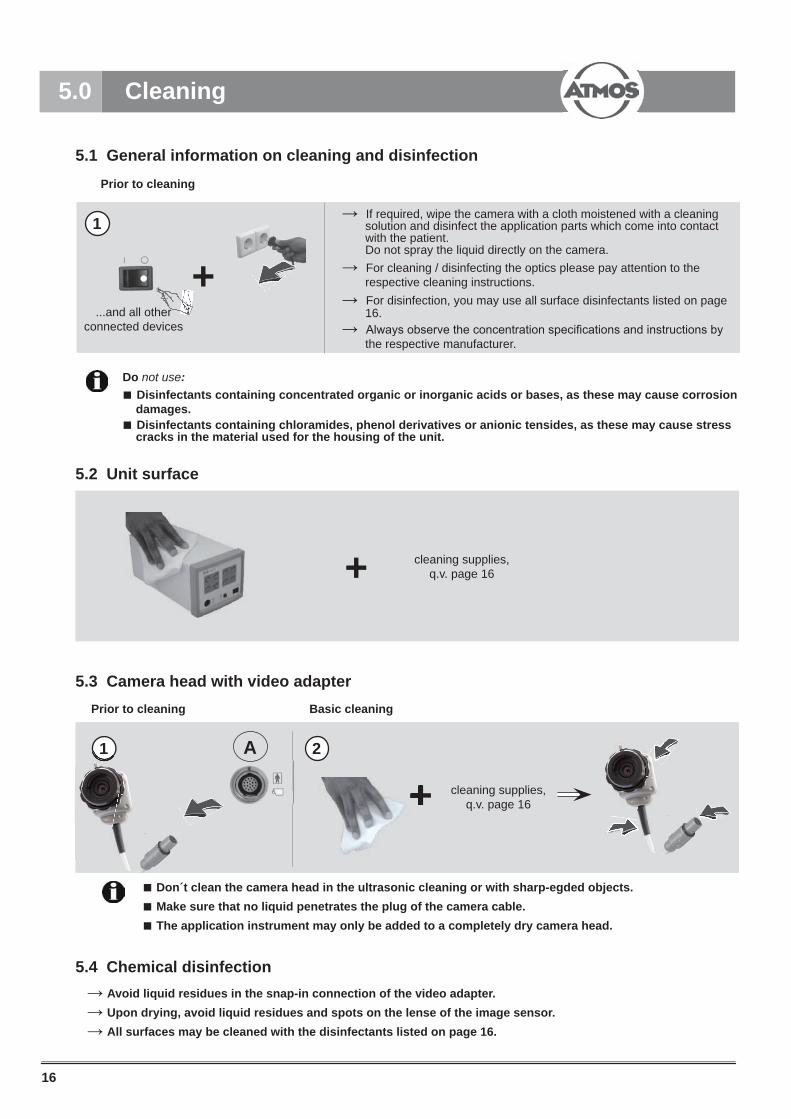
5.1 General information on cleaning and disinfection
5.4 Chemical disinfection
5.3 Camera head with video adapter
5.2 Unit surface
Do not use: Disinfectants containing concentrated organic or inorganic acids or bases, as these may cause corrosion damages. Disinfectants containing chloramides, phenol derivatives or anionic tensides, as these may cause stress cracks in the material used for the housing of the unit.
cleaning supplies, q.v. page 16
5.0 Cleaning
Prior to cleaning
...and all otherconnected devices → Always observe the concentration specifi cations and instructions by
the respective manufacturer.
→ If required, wipe the camera with a cloth moistened with a cleaning solution and disinfect the application parts which come into contact with the patient. Do not spray the liquid directly on the camera.
→ For disinfection, you may use all surface disinfectants listed on page 16.
Prior to cleaning
Don´t clean the camera head in the ultrasonic cleaning or with sharp-egded objects. Make sure that no liquid penetrates the plug of the camera cable. The application instrument may only be added to a completely dry camera head.
Basic cleaning
→ Avoid liquid residues in the snap-in connection of the video adapter.→ Upon drying, avoid liquid residues and spots on the lense of the image sensor.→ All surfaces may be cleaned with the disinfectants listed on page 16.
cleaning supplies, q.v. page 16
→ For cleaning / disinfecting the optics please pay attention to the respective cleaning instructions.
+1
17
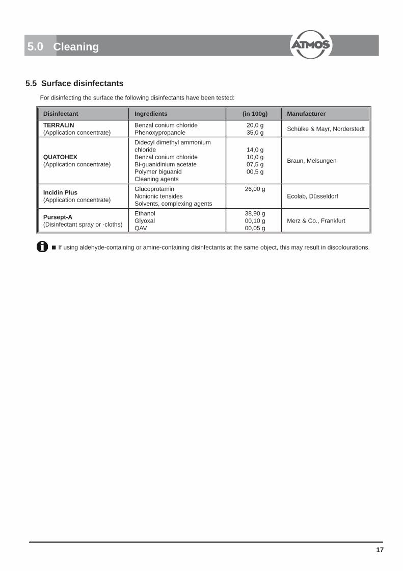
Disinfectant Ingredients (in 100g) Manufacturer
TERRALIN (Application concentrate)
Benzal conium chloridePhenoxypropanole
20,0 g35,0 g Schülke & Mayr, Norderstedt
QUATOHEX(Application concentrate)
Didecyl dimethyl ammonium chlorideBenzal conium chlorideBi-guanidinium acetatePolymer biguanidCleaning agents
14,0 g10,0 g07,5 g00,5 g
Braun, Melsungen
Incidin Plus(Application concentrate)
GlucoprotaminNonionic tensidesSolvents, complexing agents
26,00 gEcolab, Düsseldorf
Pursept-A(Disinfectant spray or -cloths)
EthanolGlyoxalQAV
38,90 g00,10 g00,05 g
Merz & Co., Frankfurt
5.0 Cleaning
5.5 Surface disinfectants
If using aldehyde-containing or amine-containing disinfectants at the same object, this may result in discolourations.
For disinfecting the surface the following disinfectants have been tested:
18
clickclick
++
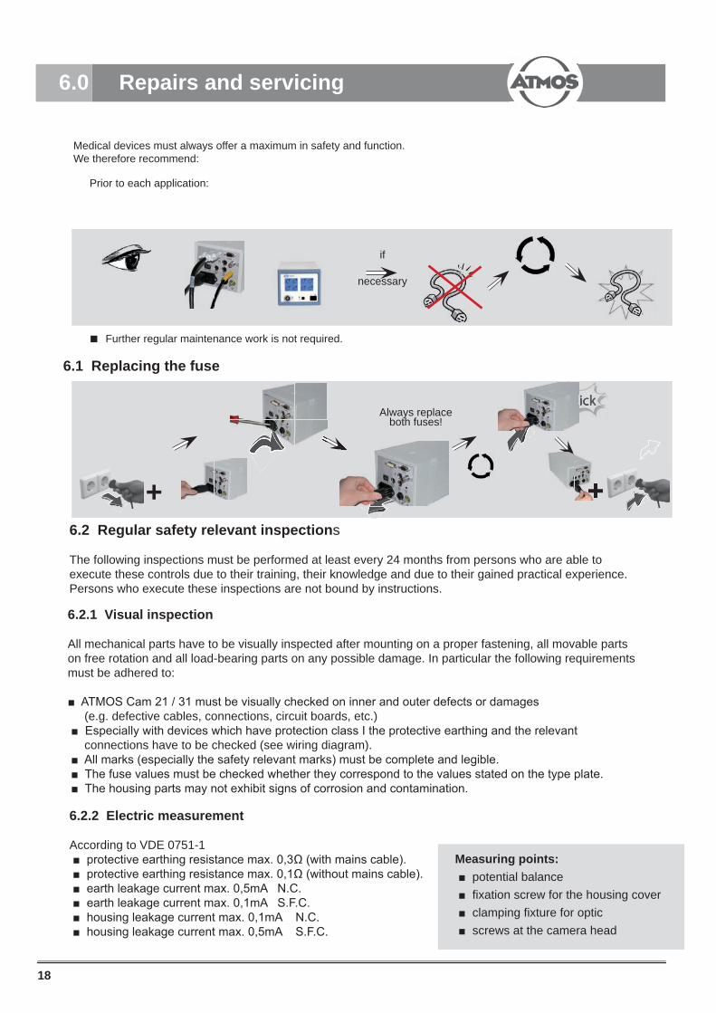
Medical devices must always offer a maximum in safety and function. We therefore recommend:
Further regular maintenance work is not required.
6.1 Replacing the fuse
6.0 Repairs and servicing
Always replace both fuses!
Prior to each application:
if
necessary
6.2 Regular safety relevant inspections
The following inspections must be performed at least every 24 months from persons who are able to execute these controls due to their training, their knowledge and due to their gained practical experience. Persons who execute these inspections are not bound by instructions.
6.2.1 Visual inspection
All mechanical parts have to be visually inspected after mounting on a proper fastening, all movable parts on free rotation and all load-bearing parts on any possible damage. In particular the following requirements must be adhered to:
ATMOS Cam 21 / 31 must be visually checked on inner and outer defects or damages (e.g. defective cables, connections, circuit boards, etc.) Especially with devices which have protection class I the protective earthing and the relevant connections have to be checked (see wiring diagram). All marks (especially the safety relevant marks) must be complete and legible. The fuse values must be checked whether they correspond to the values stated on the type plate. The housing parts may not exhibit signs of corrosion and contamination.
6.2.2 Electric measurement
According to VDE 0751-1 protective earthing resistance max. 0,3Ω (with mains cable). protective earthing resistance max. 0,1Ω (without mains cable). earth leakage current max. 0,5mA N.C. earth leakage current max. 0,1mA S.F.C. housing leakage current max. 0,1mA N.C. housing leakage current max. 0,5mA S.F.C.
Measuring points: potential balance fixation screw for the housing cover clamping fixture for optic screws at the camera head
click
+

19
7.0 Trouble shooting
Description Possible causes and measuresNo image - Are monitor and camera switched on?
- Check monitor adjustment- Is the video cable correctly inserted?- Check cable connection from camera head to control device- Check fuses
Image dark or not in focus - Optimize focusing and defi nition (see chapter 4.3.2, page 12) - Are there any residues on the optical instrument, the TV-adapter or the camera head?- Check monitor adjustment- Select brighter light source resp. usa a better application instrument
Image shows unnatural colours - Effect a white balance (see chapter 4.6.1 page 14) - Readjust colour saturation regulator on the monitor
Image shows changed colours from different angles
- Color effect with TFT monitors: misinterpretation by colour variations caused by wrong vieweing angle. Your seating position must be frontal to the monitor.

20
8.0 Accessories and spare parts
8.1 AccessoriesTFT monitor17“ TFT monitor (medical power pack) with video input and PC-monitor input (XGA)
534.3010.0
Extension cord for camera head (2.0 m)Enables the use of the camera head in a greater distance from the control module. Max. 1 extension cord may be usederlängerungskabel eingesetzt werden.
008.0884.0
LED light source ATMOS LS 21 LED white light 507.4600.0LED light source ATMOS LS 21 LED warm white 507.4602.0ATMOS MedDoc set (German)Laptop including video and image archiving software ATMOS MedDocfor archiving the diagnostic results in a patient data base
507.3221.0
ATMOS MedDoc set (English) 507.3222.0Connecting cable (0.5 m) data transfer Strobo 21 LED(included in scope of delivery Cam DATA) 507.5016.0
Audio cable (1.2 m) for transmission of the audio signal for video archiving(included in scope of delivery Cam DATA) 008.0858.0
Adapter plug for audio cable (included in scope of delivery Cam DATA) 008.0859.0
DVI-I cable (2 m) for digital connectionfrom PC-monitor over the DVI-I-interface 507.5019.0
PC monitor cable (1.8 m) for analogous connection of PC-monitors (XGA) 507.5018.0Video cable for connectionof analogous videomonitors S-VHS-monitor cable (1.0 m) 008.0635.0
Video cable for connection of analogous videomonitors S-VHS-monitor cable professional (5.0 m) 008.0882.0
Video cable for connection of analogous videomonitors FBAS-monitor cable (1.0 m) 008.0844.0
Connecting cable for digital video archiving over DV connectionFireWire cable, 1.0 m (6-4-poles) for connection to laptop(included in scope of delivery ATMOS Cam DV)
507.4260.0
Connecting cable for digital video archiving over DV connectionFireWire cable, 1.0 m (6-6-poles) for connection to medical PC(included in scope of delivery ATMOS Cam DV)
507.4261.0
Foot controller for integrated image memory in the camera(included in scope of delivery ATMOS Cam 31) 507.4034.0
!

21
8.0 Accessories and spare parts
8.2 Spare partsCamera head including connecting cable 507.5200.0Power supply cable 507.0859.0Video cable S-VHS (Y/C) 008.0671.0Operating instructions 507.3006.BAdapter 008.0859.0
8.2 OptionsEndoscopy TrolleyFor integration of camera, stroboscope, endoscope management, monitor bracket, insulation transformerand foot control band.
950.0223.0
Endoscopy Trolley for Medical PCFor integration of camera, stroboscope, endoscope management, monitor bracket, insulation transformerand foot control band.
950.0226.0
Transformer 950.0225.0Monitor bracket for Endoscopy trolley 950.0224.0
Optical instruments
Laryngoscopes Laryngoscope 70°, Ø 10 mm, working length: 176 mm,autoclavable, without light guide
950.0209.0
Laryngoscope 90°, Ø 10 mm, working length: 174 mm,autoclavable, without light guide 950.0210.0
Laryngoscope 70°, Ø 8 mm, working length: 166 mm,autoclavable, without light guide
950.0246.0
Tele-magnifying laryngoscope 70°, Ø 10 mm, working length: 147,5 mm, can be immersed, without light guide
950.0211.0
Tele-magnifying laryngoscope 90° , Ø 10 mm, working length: 145 mm, can be immersed, without light guide
950.0212.0
Ear endoscopes Wide-angle optic, 0°,working length: 50 mm, Ø 4 mm, autoclavable 950.0213.0
Wide-angle optic, 30°,working length: 50 mm, Ø 4 mm, autoclavable 950.0214.0
Wide-angle optic, 0°, working length: 34 mm, Ø 2,7 mm, can be immersed, incl. adapter for ear-speculum
950.0215.0
Nose/Pharynx endoscopes Ø 4 mmWide-angle optic, 0°, working length: 180 mm, Ø 4 mm, autoclavable 950.0216.0
Wide-angle optic, 30°, working length: 180 mm, Ø 4 mm, autoclavable 950.0217.0
Wide-angle optic, 45°, working length: 180 mm, Ø 4 mm, autoclavable 950.0218.0
Wide-angle optic, 70°, working length: 180 mm, Ø 4 mm, autoclavable 950.0219.0
Nose/Pharynx endoscopes wide angle Ø 2.7 mmWide-angle optic, 0°,working length: 110 mm, Ø 2.7 mm, autoclavable 950.0220.0
Wide-angle optic, 30°, working length: 110 mm, Ø 2.7 mm, autoclavable
950.0221.0
Flexible endoscopes High-resolution Naso-Pharyngoscope Ø 3.8 mm,
working length: 300 mm,0°, - angle of fi eld of view: 80° depth of focus: 5 mm – infi nite angle: 125° / 125°
Delivered including aluminium transport case and density verifying
950.0222.0
0° 30° 45° 70° 90°

22
ATMOS Cam 21 ATMOS Cam 31
Image sensor
⅓“ CCDResolution 752 (H) x 582 (V) PixelsDynamics 48dBMin. illumination 0,25 lux
Image memory no 1-resp. 4-image-mode
Digital zoom up to factor 2.0
White balance automatic as well as manual (with storage)
InletsConnection for camera head Data, interface for data communication with LED Strobo Audio-In: Line-In-inlet for audio signal from LED Strobo, inlet for foot switch for freezing the examination images
Outlets
Y/C (S-VHS), FBAS (video), trigger outlet (external image memory), SXGA(analogue standard monitor inlet with a resolution of 1280 x 1024 Pixel and a refresh rate of 60 Hz), current source for LED emitterOnly applicable for ATMOS Cam 21/31 DV:ATMOS interlink, IEEE 1394 (DV)*, DVI-I (digital DVI interface with integrated analogue video signal. The resolution is 1280 x 1024 pixel up to a refresh rateof 60 Hz
Only applicable for ATMOS Cam 21/31 DVAudio in**
max. input level +6 dBu (~1.54 Vrms)
TV system NTSCMains supply 100-240V AC, 50/60 HZPower consumption max. 35 VAFuses 2x T 2.5 A / HProtective earth conductor resistance max. 0.1 Ω
Earth leakage current max. 0.5 mAEnclosure leakage current max. 0.1 mAPatient leakage current max. 0.1 mARegular safety-related inspection see 6.2, page 17
Protection class IDegree of protection of application parts BF
Operation mode Continuous operationProtection category IP20Ambient conditions
Transport andstorage conditions
Temperature +10 ... +35°CAir humiditywithout condensation 30 ... 80% rel. humidityAir pressure 700 ... 1060 hPa
Temperature -10 ...+50°CAir humiditywithout condensation 30 ... 80% rel. humidityAir pressure 500 ... 1060 hPa
Classifi cation acc. to, EEC Directive 93/42/EEC, Appendix IX
I
CE marking CE
9.0 Technical specifi cations
* Video formats: PAL − 720 x 576 @ 25fps NTSC − 720 x 480 @ 29,97fps Data rate: 100 Mbps** Audio format: 1 channel 48 kHz 16 Bit
Onl
y ap
plic
able
for A
TMO
S
Cam
21/
31 D
V
Canadian Classifi cation:Device Group General & Plastic SurgeryPNC 79FWLRisk Class 1Description CAMERA, CINE, ENDOSCOPIC; WITHOUT AUDIO
23
10.0 Disposal10.1 Checking ATMOS devices
The ATMOS devices are maintenance-free in the case they are used according to the operating instructions. However, regular safety-relevant checks have to be performed in line with the BGV A3/GUV 2.10 (MPBetreibV §2 Abs. (8)). “For mobile devices the safety-relevant controls must be performed at least every 6 months.”
Regular, thoroughly cleaning and disinfection of the hoses and the application parts respectively the operation in line with theoperating instructions are assumed.
10.2 Disposal
The ATMOS Cam 21/31 does not contain any hazardous materials.
The housing is recyclable.
Device and accessories must be decontaminated prior to disposal.
Please take care on a careful separation of the different materials.
Please observe national disposal regulations (e.g. waste incineration).
Disposal within the EC
The device described above is a high-quality medical product with a long service life. After its life cycle it must be disposed of professional. According to the EC directives (WEEE and RoHS) the device may not be disposed of in domestic waste. Please observe existing national laws and rules for disposal of old devices.
Disposal within the Federal Republic of Germany
In the Federal Republic of Germany the law for electrical devices (ElektroG) rules the disposal of electrical devices. In order to guarantee a proper disposal of your old device, please either pass on your old device to your specialised dealer or send it direct-ly to ATMOS MedizinTechnik for a professional disposal.
Before disposal respectively before transport all parts, which came into contact with the patient must be thoroughly cleaned, disinfected/sterilised. The device surface must be disinfected.
Canadian Classifi cation:Device Group General & Plastic SurgeryPNC 79FWLRisk Class 1Description CAMERA, CINE, ENDOSCOPIC; WITHOUT AUDIO

24
11.0 Arrangement
Application parts Light sources
Halogen light source
Xenon light source
Endo Stroboscope L light source
LED light source1)
Laryngoscope
Naso-pharyngoscope
ATMOS-mikroscope
EndoscopeCamera head with endoscope adapter
Video-monitor
1) not applicable with microscope2) solution in combination with your computer respectively network partner
Video processing and archiving in standard video format (S-VHS,
FBAS)2)
11.1 Connection posibilities of ATMOS Cam 21 / 31
analog digital
IEEE 1394 Valid for ATMOS Cam 21/31 DV
Inte
rlink D
ata
in standard video format (S-VHS,
camera control unit unit unit
camera control camera control camera control camera control camera control camera control camera control camera control camera control camera control unit unit
camera control camera control camera control camera control
endoscope adapterendoscope adapter

25
12.0 Notes on EMC
12.1 Guidelines and Manufacturer´s Declaration - Emissions The ENT-camera Cam 21 / 31 is intended for use in the electromagnetic environment specifi ed below. The customer or user of the Cam 21 / 31 should ensure that it is used in such an environment.
Emissions Test Compliance Electromagnetic Environment - GuidanceRF Emissions CISPR 11
Group 1 The ENT-camera Cam 21 / 31 uses RF energy only for its internal function. Therefore, its RF emissions are very low and are not likely to cause any inter-ference in nearby electronic equipment.
RF Emissions CISPR 11
Class B The Cam 21 / 31 is suitable for use in all esta-blishments, including domestic, and those directly connected to the public low-voltage power supply network that supplies buildings used for domestic purposes.
Harmonics IEC 61000-3-2 InapplicableFlicker IEC 61000-3-3
Inapplicable
12.2 Guidelines and Manufaturer´s Declaration - Immunity
The ENT-camera Cam 21 / 31 is intended for use in the electromagnetic environment specifi ed below. The customer or user of the Cam 21 / 31 should ensure that it is used in such an environment.
Immunity Test IEC 60601-Test Level Compliance Level Electromagnetic Environ-
ment - GuidanceESD IEC 61000-4-2
± 6 kV Contact
± 8 kV Air
± 6 kV Contact
± 8 kV Air
Floors should be wood, concrete, or ceramis tile. If fl oors are synthe-tic, the relative humidity should be at least 30%.
EFTIEC 61000-4-4
± 2 kV Mains
± 1 kV I/Os
± 2 kV for mains cables Mains power quality should be that of a typical commercial or hospital environment.
SurgesIEC 61000-4-5
± 1 kV Differential± 2 kV Common
± 1 kV symmetric
± 2 kV symmetric
Mains power quality should be that of a typical commercial or hospital environment.
Power Frequency 50/60 HzMagnetic fi eld IEC 61000-4-8
3 A/m Power frequency magnetic fi elds should be that of a typical com-mercial or hospital environment.
Medical electrical equipment is subject to special precautions with regard to EMC and must be installed acc. to following EMC notes.
Portable and mobile HF communication facilities can influence medical electrical equipment.
The use of other accessories, other converters and cables than stated may lead to an increased emission or a reduced interference immunity of the equipment or system.

26
12.0 Notes on EMC
Immunity Test IEC 60601-Test Level
Compliance Level Electromagnetic Environ-ment - Guidance
Voltage Dips / DropoutIEC 61000-4-11
< 5 % UT (> 95 % Dip of the UT) for 0.5 Cycle
40 % UT(60% Dip of the UT) for 5 Cycles
70% UT(30 % Dip of the UT) for 25 Cycles
< 5 % UT (>95 % Dip of the UT) for 5 s
< 5 % UT (> 95 % Dip of the UT) for 0.5 Cycle
40 % UT(60% Dip of the UT) for 5 Cycles
70% UT(30 % Dip of the UT) for 25 Cycles
< 5 % UT (>95 % Dip of the UT) for 5 s
Mains power quality should be that of a typical commercial or hospital environment. If the user of the Cam 21 / 31 demands continued function even in case of interrup-tions of the energy supply, it is re-commended to supply the Cam 21 / 31 from an uninterruptible current supply or a battery.
NOTE UT is the mains alternating current prior to application of the test levels.
12.3 Guidelines and Manufacturer´s Declaration - Immunity The ENT-camera Cam 21 / 31 is intended for use in the electromagnetic environment specified below. The customer or user of the Cam 21 / 31 should ensure that it is used in such an environment.
Immunity Test IEC 60601-Test Level Compliance Level Electromagnetic Environment
- GuidancePortable and mobile communications equipment should be separated from the ATMOS Cam 21 / 31 incl. the cables by no less than the distances calculated/listed below.
Recommended distances:d = 1.17 √Pd = 1.17 √P for 80 MHz to 800 MHzd = 2.33 √P for 800 MHz to 2.5 GHzwhere „P“ is the max. power in watts (W) and D is the recommended separation distance in meters (m).
Field strengths from fixed transmitters, as determined by an electromagnetic site (a) survey, should be less than the compli-ance level (b). Interference may occur in the vicinity of equipment containing following symbol.
Conducted RFIEC 61000-4-6
3 Veff150 kHz to 80 MHz
3 Veff150 kHz to 80 MHz80% AM 1kHz
Radiated RFIEC 61000-4-3
3 V/m80 MHz to 2.5 GHz
3 V/m80 MHz to 2.5 GHz

27
12.0 Notes on EMC
12.4 Recommended separations between portable and mobile RF Communications equipment and the ENT-camera ATMOS Cam 21 / 31
NOTE 1 With 80 MHz and 800 MHz the higher frequency range applies.
NOTE 2 These guidelines don´t like to be applicable in any case. The propagation of electromangetic sizes is influenced by absorptions and reflections of buildings, objects and people.a The field strength of stationary transmitters, such as base stations of cellular phones and mobile terrain radio equipment, amateur radio transmitters, cbm broadcast and TV stations cannot be predestined exactly. To determine the electromagnetic environment in regard to stationary transmitters, a study of the location is to be considered. If the measured field strength at the location where the ATMOS Cam 21 / 31 is used exceeds the above compliance level, the ATMOS Cam 21 / 31 is to be observed to verify the intended use. If abnormal performance characteristics are noted, additional measures might be necessary, e. g. a changed arrangement or another location for the device.
b Within the frequency range of 150 kHz to 80 MHz the field strength is to be below 3 V/m.
The ATMOS Cam 21/31 is intended for use in electromagnetic environment in which ratiated disturbances are controlled. The customer or user of the ATMOS Cam 21 / 31 can help prevent electromagnetic interference by maintaining a minimum distance between portable and mobile RF Communications equipment and the ATMOS Cam 21 / 31 as recommended below, according to the maximum output power of the communications equip-ment.
Separation distance, depending on transmit-frequency mNominal output of the
transmitter
W
150 kHz to 80 MHz
d = (3.5/V1) √P
80 MHz to 800 MHz
d = (3.5/E1) √P
800 MHz to 2.5 GHz
d = (7/E1) √P
0.1 0.12 0.12 0.230.1 0.37 0.37 0.741 1.17 1.17 2.3310 3.69 3.69 7.38100 11.67 11.67 23.33
For transmitters for which the maximum nominal output isn´t indicated in the above table, the recommended sepa-ration distance d in meters (m) can be determined using the equation belonging to the respective column whereas P is the maximum nominal output of the transmitter in watts (W) acc. to manufacturer´s specification.
NOTE 1 With 80 MHz and 800 MHz the higher frequency range applies.
NOTE 2 These guidelines don´t like to be applicable in any case. The propagation of electromagnetic sizes is influenced by absorptions and reflections of buildings, objects and people.

28

MedizinTechnik
This catalogue is copyrighted. Duplication, translations, microfilming and savings on electronic systems, particularly for commercialpurposesare illegal without prior agreement of the manufacturer. All compiled data are based on manufacturers instructions. All logos,product names and designations used in this catalogue are property of the respective manufacturer.We do not take over any warranty and liability in the case of missing inscriptions. Subject to modifications and amendments.
1. General:Our General Standard Terms and Conditions apply exclusively. Client’s terms and conditions which are contrary to or deviate from our General Standard Terms and Conditions are not recognised unless their validity is explicitly confirmed in writing. Our General Standard Terms and Conditions also apply even if we deliver to clients without reservation, in the knowledge of the client’s contrary terms and conditions. Our General Standard Terms and Conditions also apply to all future business with that client.
2. Proposal - Order Confirmation Our proposals are subject to change without notice unless otherwise stated in our order confirmation. Each order is only accepted by us following our written order confirmation.
3. Orders Every order requires an exact description of all of our product’s details. We assume no liability for errors and damage caused by inaccurate or incomplete ordering details.
4. Prices Unless otherwise stated in the order confirmation, our prices in the order confirmation are ex factory prices and exclude packaging and value added tax. Packaging is charged separately at cost price in the invoice. Value added tax is charged separately in the invoice according to the legal rate on the invoice date. We reserve the right to change prices appropriately should price reductions or increases, especially due to wage settlements, changes in the price of materials or currency fluctuations, be incurred. Proof of such changes will be provided for the client on request.
5. Payment Conditions - Balancing Unless otherwise stated in the order confirmation, our invoices are payable with a 3% discount within 10 days (except for repair and assembly services) or within 21 days from the invoice date net cash; money receipts is decisive for complying with this term. We are entitled to charge interest after the due date at a rate 2% above the relevant basic interest rate of the German Federal Bank. Should the client have payment arrears, we are entitled to charge interest on arrears at a rate 5% above the relevant basic interest rate of the German Federal Bank. Should we be able to prove higher damages due to arrears, we are also entitled to claim these. The client only has the right to balance invoices against its own claims should such claims be confirmed in a court of law or recognised by us. The client does not have the right of retention due to disputed counterclaims.
6. Delivery Periods Fulfilment of our delivery duties requires the punctual and proper fulfilment of the client’s duties. The right to defense on the grounds of an unfulfilled contract is reserved.Should the client default in accepting the goods delivery or breach other cooperation duties, we are entitled either to withdraw from the contract or claim compensation for any increased costs incurred up to that time without setting a further deadline. The right to make further claims is reserved. Furthermore, in such cases, the risk of coin-cidental destruction or a coincidental deterioration in the quality of the delivered goods is transferred to the client in the case of default in accepting such goods or payment arrears. Acts of God or stoppages (due to insufficient supplies of material, industrial disputes etc.) entitle us either to demand an appropriate extension of delivery periods or to partly or entirely dissolve the delivery contract. This does not give the client the right to claim damages. We have fulfilled delivery periods if the delivery goods have left our factory or the client has been informed of the goods’ readiness for delivery within such delivery periods. Delivery periods stipulated by the client are not recognised by us unless they form part of our order confirmation. We adhere to legal terms and conditions in cases where, as a result of an undue delay in the delivery for which we are liable, the client is entitled to claim that his interests in a continued fulfilment of the contract have ceased. We also adhere to legal terms and conditions should a delay in delivery be caused by deliberate or grossly negligent action by us or our representatives for which we are responsible. We are also responsible for such actions by our representatives or agents. Should the delivery delay not be caused by our deliberate infringement of contractual duties for which we are responsible, our liability is limited to damage which is regarded as typical for that case. We are liable according to the legal terms and conditions if and in so far as the delivery delay for which we are responsible is caused by an infringement of a substantial contractual duty. In such cases, our liability is also limited to damage which is regarded as typical for that
case. Should the delivery delay be caused by a culpable infringement of non-substantial contractual duties, our client is also entitled to claim a one-off damage compen-sation worth 3 percentage points of the delivery value of the goods for each week’s delay, up to a maximum which is no higher than 15 percentage points of the delivery value of the goods
7. Delivery - Familiarisation In the case of the delivery of devices for the medico-technical industry which require assembly and/or familiarisation for the final customer using specialist trade personnel (such as Ear, Nose and Throat Apparatus and Suction Units), we reserve the right to deliver the goods exclusively to the relevant specialist traders. Should the trader not carry out assembly and/or familiarisation for the final customer, this is carried out by us. In such cases, we reserve the right to charge the client for the additionally created costs. Our specialist traders operate a recording system so that, if necessary, our products can be traced to the final customer. The specialist trader undertakes to immediately report to us all events and risks which must be reported in connection with our products.
8. Passage of Risk - Packaging Unless otherwise stated in our order confirmation, delivery is agreed ex factory. The risk of the goods’ damage or loss is therefore transferred to the client as soon as the goods leave the factory or the client is in default of acceptance of the goods. This also applies to cases where we confirm prepaid carriage. Transport packaging and all other packaging according to the packaging regulations is not returnable. Our client is responsible for disposing the packaging at its own cost. Our deliveries are insured by us at the client’s expense unless explicitly otherwise agreed. No insurance is arranged in the case of goods which are collected by our clients. In the case of transport damage, claims are only handled if the client receives confirmation of any damage, reduced weight or loss by the shipping company before accepting the delivery.
9. Warranty The client is responsible for examining the delivered goods immediately after receiving them to determine any eventual deficiencies or delivery errors, and to report these immediately. Should the client fulfil this examining and reporting responsibility, and should payment conditions be fulfilled, we shall be liable to the client within the scope of legal regulations. Our period of warranty shall in all cases be two years. Our client can make use of the warranty as follows, so long as he can provide first buyer proof (in the form of an invoice or delivery note) and provided that the product still has the original, unchanged serial number: a. We choose whether to fulfil our guarantee by providing repair
services free of charge - either on the client’s premises or in our factory - or replacing the product. We can also provide these guarantee services through an authorised company;
b. Should a product be returned to us, the client agrees to send the product in its original or similar packaging, offering the same protection as the original packaging, to our address or any address notified by us.
c. Our guarantee ceases to apply if changes of any kind have been made to our product, unless such changes have been made by us or a company authorised by us, or have been previously agreed upon in writing by us. Our guarantee also ceases to apply if third parties have carried out repairs to our products or replaced parts thereof. This applies regardless of the fact whether these measures individually or collectively led to a deficiency of the product;
d. We accept no responsibility for damage defects caused by - operational wear and tear; - incorrect installation or incorrect or insufficient maintenance; - incorrect operation of the product (in contradiction to the handbook delivered with the product); - improper use or operating faults; - inappropriate or negligent handling and care, especially with respect to dirt, lime, suction of fluids, inappropriate cleaning and sterilisation;
- using accessories and/or replacement parts which are not explicitly approved; - incorrect assembly and/or initial operation by the client or third parties; - the client’s negligence in handling the product; - unacceptable operating conditions, such as humidity, temperatures, the power supply, vibrations. - accidents, acts of God, especially lightening, water, fire, public unrest and insufficient ventilation. We are not liable for damage to other objects apart from our product itself, except in the case of any deliberate or grossly negligent actions by us or our representatives or agents. Should no deliberate breach of contract be claimed, our liability
is limited to damage which is regarded as typical for tthat case. This also applies in the case of our culpable infringement of substantial contractual duties The indispensable conditions of German Liability Law remain unaffected thereby. - For second-hand equipment, the period of warranty shall be reduced to a period of twelve months.
10. Reservation of Ownership We retain ownership of our goods until the receipt of all payments arising from the business relationship, including all demands arising from installation orders, subsequent orders, repairs, accessory deliveries and replacement orders. Should we have agreed upon payment on the basis of cheque and bill transactions, the ownership reservation applies until the cheque received by us has been paid in, and does not expire through our credit upon receiving the client’s cheque. In the case of a breach of contract by the client, especially payment arrears, we are entitled to repossess our goods. Repossession of our goods repre-sents a withdrawal from the contract, unless explicitly declared in writing by us. We have the right to utilise the product after its repossession, whilst the income form such use is balanced against the client’s arrears, after deducting appropriate utilisation costs.The client is responsible for handling the goods with care. Should maintenance and inspection work be necessary, the client must carry these out punctually at his own cost. Our client is entitled to sell the goods he has bought from us in a proper sale transaction. However, he must immediately assign all outstanding claims to the value of the final invoice sum (including value added tax) of our claims to his customers or third parties. The client is entitled to collect this claim even after such assignment. Our right to collect the claim ourselves remains unaffected thereby.We undertake to release the securities to which we are entitled if requested to do so by the client should the realisable value of the our securities be more than 10 percentage points higher than the outstanding claims. We reserve the right to choose the securities to be released.
11. Plans and Illustrations We retain ownership of and copyrights to all plans, illustrations, calculations and other documents which are attached to our proposals. The client must receive explicit written permission before passing these on to third parties. Imitating our legally patented products is forbidden and will be prosecuted.
12. Jurisdiction and Place of Performance Our central office is the place of performance for all disputes in connection with these General Standard Terms and Conditions and the contracts closed with clients under them. This jurisdiction excludes other jurisdiction relating to persons or subject-matter. Furthermore, our client is not entitled to bring charges against us in another court should he file counter-charges, carry out counterbalancing or declare retention. We, however, are entitled to bring charges against our client at their general place of jurisdiction or at another relevant court recognised by German or foreign law.Unless otherwise stated in the order confirmation, our central office is the place of performance.
Lenzkirch, September 2008ATMOS MedizinTechnik GmbH & Co. KG79853 Lenzkirch/Germany
ATMOS General terms and conditions